strengthening and rehabilitation techniques for masonry...
TRANSCRIPT
NineteenthInternational Water Technology Conference, IWTC19SharmElSheikh, 21-23 April 2016
265
STRENGTHENING AND REHABILITATION TECHNIQUES FOR MASONRY
HYDRULIC STRUCTURES - A CASE STUDY (PART1- ASSESSMENT)
A. S. Hashad
1, And M. I. Abukhashaba
2
1 Associate Professor, Construction Research Institute, Egypt, E-mail:[email protected]
2Professor, Construction Research Institute, Egypt, E-mail: [email protected]
ABSTRACT
Barrages are considered one of the most important water structures in Egypt. It is very important to
keep them working in good condition to assure water management in good manner. Most of these
barrages have been built many decades ago using burned clay bricks and still in service till now. The
construction cost of new barrages is very expensive, so, maintaining, repairing and strengthening these
structures are an economical option that cannot be ignored. Many reasons cause defects in masonry
hydraulic structures. These defects affect the structure capacity and performance. The causes of
defects should be understood to be treated in optimum way. Structure assessment is the basic step to
restore the structural capacity and to assign the suitable repairing technique. The aim of this paper is
to present guidelines for the assessment of the masonry barrages when repairing, strengthening or
upgrading is required. This could be achieved through reviewing the international experience in that
field beside the gained experience from the many barrages upgrading projects. The paper displays a
case study for assessment process for a typical masonry barrage type in Egypt. This study provides a
solid basis for integrating all the monitored/output data into practical assessment of barrage system
performance.The results of this study can also help to develop the current design codes.
Keywords:Masonry Structures, Hydraulic Structures, Structural Assessment, Deterioration
1 INTRODUCTION
Most of the masonry barrages in Egypt are relevant to heritage buildings. Several advantages could
be achieved by maintaining and continual using of these facilities such that, Preserving their
distinctive architectural character, environmental, social and economic value.Old masonry structures
in Egypt were designed based on experience, without explicit structural calculation. Working with
masonry design Codes began after the fifties in the last century. The early published documents were
based on allowable-stress and empirical design and seismic design requirements were not
included.The current Egyptian specification for design of masonry structures is strength-based design
provisions (ECP 203, 2005) and there is a separate specification for design loads values applied on
structures and their combinations (ECP 203, 2012). The assessment process is the effort that must be
done to answer this simple question: "Is the building in conformity with the requirements of the
current construction codes?".And it will be useful in order to get your answer to this question to be
sure from the beginning that this building was in valid conditions with the specifications in the period
when the structure was designed.
In general, the assessment procedure was carried out by specialized engineers with intensive
practical experience (Holický, M. et al., 2013). The assessment process starts with visual inspection to
obtain a good feel for actual situation and state of the structure. Visual inspection of the assessed
structure should be made whenever possible. The main principal in visual inspection is to avoid
negligence of any structural condition that may affect actual reliability of a given structure. The
assessment process in general consists of two stages as follows:

NineteenthInternational Water Technology Conference, IWTC19SharmElSheikh, 21-23 April 2016
266
Initial assessment step which includes
Preliminary inspection, Study of available documentation,Preliminary checks, Recommendation for
an immediate actions and Detailed assessment.
Final assessment step which includes
Assignspecification of the assessment scenarios related to structural conditions and actions,
Detailed inspection, Detailed structural analysis,Full validation of original documents, Verifying the
objectives required by the client authority.
When the preliminary assessment indicates that the structure is reliable for its intended use over the
remaining life a detailed assessment may not be required. Conversely if the structure seems to be in
dangerous or uncertain condition immediate interventions and detailed assessment may be
necessary.The evaluation of structural reliability is a basic step of assessment process and be done
through applying a verification technique carried out by structural analysis using: actual characteristics
of structural materials those were determined through material testing process, structure properties to
determine forces and its actions, as built geometric data and structure conditions, and check results
taking into consideration structural behavior.
2 BACKGROUND
Most of the Egyptian barrages are constructed using masonry/brick as a construction material and a
structural system consists of arches carried by piers rested on mattress/raft foundation. The aim of the
assessment is to establish the safe load carrying capacity of the masonry barrage. Assessments should
not be extremely conservative, resulting in unnecessary remedial action, or so lax that they impose an
unacceptable risk to the public. The basic requirement in the assessment process is to get a good
balance between safety and economy. The strength assessment or evaluation of an existing barrage
becomes necessary for the following reasons:
• The structure has seriously deteriorated or suffered substantial damage resulting in a decrease in
strength.
• There has been a change in design codes which may mean a reduction in acceptable safety levels.
• Raising water levels.
• It is required to carry higher traffic loads than it was designed for, due to general increase in
traffic weights, increase in traffic densities or due to the passage of an abnormal vehicle load.
If the assessment process concluded that barrage is a structurally deficient it means that the barrage
is in relatively poor condition or has insufficient load-carrying capacity. The main reasons for the
overall structural inadequacies or degradation of the masonry hydraulic structures are the original
design, overloading, seismic loading, differential settlement, overstresses induced by operation
conditions or due to material deterioration because of aging, corrosion, ingress of moisture,
temperature changes or harsh environmental exposure.
The existing shape of the old barrages is considered one of the Egyptian cultural and historic
landmarks, so it is very important to preserve such kinds of structures. Strengthening is an
improvement or upgrading the original strength and aims at one or more of the following objectives:
(1) Eliminating sources of weakness. (2) Decreasing any load or operation cases that produce stress
concentrations in some locations. (3) Avoiding the possibility of brittle modes of failure. (4) Giving
unity to the structure by providing a proper connection among its resisting elements. (5) Increasing
the overall capacity to satisfy the risk requirements.
A lot of researchers studied the assessment process for brick arch bridges and evaluated the
rehabilitation solutions. FotisP.,& Costas, Α.,(2011) were developed a simple mechanics model for the
nonlinear load–deformation relationship of the stabilized piers which was accurate enough for design
purposes. The vulnerability and the overall seismic behavior of masonry building were

NineteenthInternational Water Technology Conference, IWTC19SharmElSheikh, 21-23 April 2016
267
investigated.Determination of loading capacity of arch bridges is a sophisticated problem because of
many factors, the behavior of the construction materials, and the effect of fill material in load
resistance. Many researchers studied the different methods to determine the arch loading capacity as
done by Brencich et al.,(2002). The study presents some aspects of the assessment approach of
masonry arch bridges was developed by the Italian National Railway Authority (RFI) and the
University of Genoa. Brookes C., and Mullett P., (2004) carried out a series of service load tests have
been undertaken on a typically deteriorated bridge. Test results have shown that the strengthening
reduces intrados strains and helps to control pre-existing crack movement. Frunzio et al.,(2001) were
performed a numerical analysis by means of a nonlinear F.E.M. algorithm, showed that the results can
be useful, in case of restoration of a masonry arch.Studies were also carried out to increase the
capacity loading of masonry arches using different methods. Mullett et al.,(2006) performed a study to
describe the features of the Archtec system with particular relevance to strengthening bridges. It is
concluded that the method has significant environmental benefits and reduced cost compared with
some alternatives. Hashad et al.,(2007) displayed an evaluation process for one of the old barrages in
Egypt. The evaluation process was aimed to evaluate the strength of the construction materials and the
state of the different structural elements. The research introduced a method for increasing traffic
loading capacity for barrage by using a continuous reinforced or prestressed slab rested on its piers.
The problems related to soil problems or using foundation technques to upgrade the barrage overall
capacity were studied in a lot of researches, El-KasabyA.,(2001) discussed the barrage foundation
problems in terms of bearing capacity problem or sliding problem can be solved by using micro-piles
technique. the strengthening of Historic Buildings by the methodology of Micro-piles. DYWIDAG
systems used anchors to increase the stability in two dams in USA. Anchors were used to restore
monolithic action between construction joints which were weak points in the Stewart Mountain dam
body and to enhance its sliding resistance. The second dam was the Railroad Canyon dam where the
Anchors were used to connect the new concrete added to increase the dam height with the existing
one. Mivelaz et al.,(2006) evaluatedthe maigrauge gravity dam in Germany which is considered the
oldest concrete dam in Europe. Dam safety assessment has led to the conclusion that the dam was
deficient in meeting stability and strength criteria under severe flood and earthquake loadings. In order
to adapt the dam to modern standards, strengthening measures became necessary. Different
alternatives for the rehabilitation were analyzed and compared with regard to technical, economical
and environmental aspects. The final design consisted of the installation of 52 inclined pre-stressed
anchors drilled from the dam crest into the rock foundation. Hashad et al.,(2012) suggested a
technique to increase the ability of the hydraulic structures to resist seismic loads. The suggested
technique depends on using soil improvement methods to improve the most stressed soil bulb zone
under the structure. The effect of seismic site soil factor will be decreased by improving this soilpart.
The main problem of the masonry structures is their low resistance of lateral load especially in the
out of plane direction which causes over stress in the barrage piers during earthquakes. Many
researchers studied the upgrading of lateral capacity of masonry structures. Hernan and, et al., (2004)
tested masonry panels reinforced with externally bonded carbon fiber reinforced polymer (CFRP)
laminates and sheets subjected to in-plane shear load. Panels with two configurations of the
reinforcement were subjected to monotonic and cyclic loading. They reported the results of the tests in
terms of strength, and mechanism of failure. Hashad et al. (2007) introduced a methodology to
increase the barrage head difference capacity or to strengthen the barrage. The suggested
methodology uses cables joining all the barrage piers in a certain level. The solution enhances the
structural seismic performance and considered an economic solution. Asli, A., (2008) developed a
methodology for seismic design and evaluation of the response of the masonry structure. 4-storey
masonry residential buildings instead of multi-story reinforced concrete were proposed. They verified
that it is possible to construct a four-story residential building with masonry bearing walls instead of
reinforced concrete skeleton system without changing its architectural characteristics. El-
HakemY.,andHashad A., (2012) investigated the effect of using reinforcement and pre-stressing
techniques for strengthening masonry piers to increase the the out of plane seismic load capacity of
barrage piers.

NineteenthInternational Water Technology Conference, IWTC19SharmElSheikh, 21-23 April 2016
268
The final selection of a suitable and most effective method generally depends on simplicity, speed
of application, structural performance, practically and total cost. A study conducted by Arduni et
al.,(1997) found that the failure modes for repaired structures may change from ductile to brittle.
Durgesh C.,and Subhash C., (2007) concluded that the undesirable compressive mode of failure of
stabilized rocking piers at large drifts can be eliminated by the use of yielding energy dissipation
device to limit the forces in verticals and thereby the compression force in rocking piers. They
developed a simple mechanics model for the nonlinear load–deformation relationship of the stabilized
piers which was accurate enough for design purposes. Abu-KhashabaM.I.,Hashad A., (2013) studied
the effects of different repair techniques on the dynamic structural response of masonry barrage piers.
These techniques had been selected for their potential to either increase the structural capacity of
members or to restore the original capacity of the repaired masonry cracked piers. Efficiency of repair
works was evaluated by testing the repaired structures under seismic loads. Crack repair methods may
have a positive effect, but result in changing the pattern of collapse of structure which requires to be
considered when assessing these methods. Crack repair methods may also contribute to improve
structure integrity which making it with multiple advantages, (Robet, G. et al., 1999).
3 CASE STUDY
3.1 General Description
The ninth barrage located at kilometer 36.00 on Moyes Sea within the city of Zagazig and track
Barrage public administration Irrigation eastern east. The due date of the barrage establishment was
1923 and made up of a number of barrage (7) openings with aperture width (2.35 m) and piers display
(3.00) and lock navigation width (8.00 m). A weir behind the barrage to raise the water level was also
constructed. Barrage and all its different parts (shoulders, piers and opening arches) were constructed
as stone buildings. Barrage has been amended in 2000 to convert the lock room to the two holes each
opening (2.35 m) and strengthen the winch with a layer of reinforced concrete and pour the barrage
higher lock opening reinforced concrete (beams and slab concrete) and making front and background
parapets of stone bound with pink brick and Tlsanh of Dstoor stone and changing the operating gates
system through a metal truss on all openings. The available data do not explain the dimensions of the
barrage raft or its type, (Hikal, A., 2015). Figs 1-2 show both site description and photo of the barrage.
3.2 Purpose
The main goal is to conduct study of evaluating thestructural safety status of the barrage. It aims to
review the barrage current state and assess its stress state to determine its structural integrity case or
providing the necessary recommendations measures to ensure its safety in light of the current state of
operational loads where still barrage operate an origin to hold the water in addition to the exposure to
high traffic loads on the nature of its presence on a main axes of internal roads in Zagazig city.
Figure 1. Site description of the ninth barrage Figure 2. Photo of the ninth barrage
NineteenthInternational Water Technology Conference, IWTC19SharmElSheikh, 21-23 April 2016
269
3.3 Case Study Axes
A project plan was developed to include a number of complementary studies to be inferred on the
current condition of the barrage by the results of the structural analysis of its mathematical model
which is configured including the availability of data and information during the study period, which
lasted more than for the whole year, as a result of the operating conditions of the barrage bridge as hub
traffic area and the difficulty of prevent the highest traffic on the barrage deck for applying a loading
test experiment, and in light of the results of all the studies that has been carried out on the barrage
body and on the soil under the barrage foundations, each study has included a detailed program as will
be seen later through the axes of each study. The following studies were carried out:
1. Making a virtual preview to find out the status of barrage and a questionnaire study
requirements.
2. Conducting a structural survey to monitor and document the state of the cracks and defects.
3. Conducting raise surveyors for the barrage's structural body and completing the missing
dimensional data and making as built drawings for the barrage.
4. Conducting geotechnical study of the barrage site to determine the nature of the soil.
5. Carrying out the necessary tests for conducting a study to evaluate the properties of the
constituent materials of the barrage.
6. Carrying out the loading test on the barrage.
7. Conducting a structural analysis to determine the current stress levels on the foundations of
barrage and its body as a result of the current operating loads.
3.1.3 Visual inspection works
It should be stated that with a case study, resechersare much more of an observer than an
experimenter.A technical committee from the Construction Research Institute has formed to inspect
the site and the body of barrage and well acquainted with the surrounding site conditions in
coordination with the representative engineers for General El-sharquia irrigation administration to
discuss the nature of the barrage operating conditions,its maintenance/repair history and the results of
the periodic inspection of the barrage body.
3.2.3 Monitoring and documenting the defects and cracks case works
The study aims to document everything that can be accessed from a virtual defects and cracks in the
body of barrage, to ensure documented case of barrage before proceeding to its loading test, as well as
one of requirements essential to record the status of barrage on the date for the implementation of
documentation study even could be used as a reference to follow updates to the arch of the
manifestations defects or cracks. That study included the work of photo'ing documenting each defect
or crack to include its description, the defect place and to make a preliminary assessment of the cause
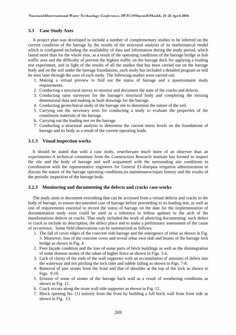
of occurrence. Some field observations can be summarized as follows:
1. The fall of cover edges of the concrete slab barrage and the emergence of rebar as shown in Fig.
3. Moreover, loss of the concrete cover and reveal rebar own slab and beams of the barrage lock
bridge as shown in Fig. 4.
2. Poor façade condition and the loss of some parts of brick buildings as well as the disintegration
of some dostoor stones of the taban of higher fence as shown in Figs. 5-6.
3. Lack of clarity of the ends of the wall supporter with an accumulation of amounts of debris into
the waterway and not pitching the lock inlet and rubble falling as shown in Figs. 7-8.
4. Removal of pier stones from the front and that of shoulder at the top of the lock as shown in
Figs. 9-10.
5. Erosion of some of stones of the barrage back wall as a result of weathering conditions as
shown in Fig. 11.
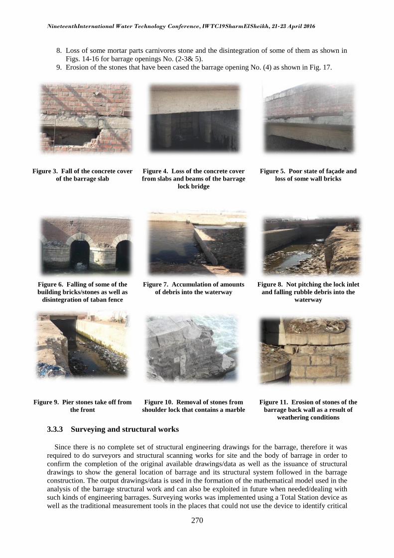
6. Crack occurs along the stone wall side supporter as shown in Fig. 12.
7. Block opening No. (1) entirely from the front by building a full brick wall from front side as
shown in Fig. 13.
NineteenthInternational Water Technology Conference, IWTC19SharmElSheikh, 21-23 April 2016
270
8. Loss of some mortar parts carnivores stone and the disintegration of some of them as shown in
Figs. 14-16 for barrage openings No. (2-3& 5).
9. Erosion of the stones that have been cased the barrage opening No. (4) as shown in Fig. 17.
Figure 3. Fall of the concrete cover
of the barrage slab
Figure 4. Loss of the concrete cover
from slabs and beams of the barrage
lock bridge
Figure 5. Poor state of façade and
loss of some wall bricks
Figure 6. Falling of some of the
building bricks/stones as well as
disintegration of taban fence
Figure 7. Accumulation of amounts
of debris into the waterway
Figure 8. Not pitching the lock inlet
and falling rubble debris into the
waterway
Figure 9. Pier stones take off from
the front
Figure 10. Removal of stones from
shoulder lock that contains a marble
Figure 11. Erosion of stones of the
barrage back wall as a result of
weathering conditions
3.3.3 Surveying and structural works
Since there is no complete set of structural engineering drawings for the barrage, therefore it was
required to do surveyors and structural scanning works for site and the body of barrage in order to
confirm the completion of the original available drawings/data as well as the issuance of structural
drawings to show the general location of barrage and its structural system followed in the barrage
construction. The output drawings/data is used in the formation of the mathematical model used in the
analysis of the barrage structural work and can also be exploited in future when needed/dealing with
such kinds of engineering barrages. Surveying works was implemented using a Total Station device as
well as the traditional measurement tools in the places that could not use the device to identify critical

NineteenthInternational Water Technology Conference, IWTC19SharmElSheikh, 21-23 April 2016
271
information needed to complete the rest of the arch studies. It should be noted that it was also a review
of the special drawings/data available to barrage and determine what is in conformity with the current
situation after barrage renovation. As built drawings were achieved such as layout of the barrage and
its surrounding area, barrage x-secs and longitudinal secs, the barrage main façade and different
detailed drawings.
Figure 12. Crack occurs in the
lateral stone wall supporter
Figure 13. Block opening No. (1)
entirely from the front by wall
building
Figure 14. Loss of some mortar
parts for stones and disintegration
of some of them for opening No. (2)
Figure 15.Loss of some mortar
parts for stones and disintegration
of some of them for opening No. (2)
Figure 16. Loss of some mortar
parts for stones and disintegration
of some of them for opening No. (3)
Figure 17. Stone disintegration for
opening No. (4)
3.4.3 Geotechnical work
The aim of this study was to determine the soil base parameters that used as a key input into the
mathematical model, which will be configured to the structural study of barrage integrity. Therefore, it
was necessary to carry out the borings needed to determine the nature of the soil beneath the
foundations of barrage. The CRI acts exploratory borings and analysis of samples and conducting
laboratory tests needed for them, and determine the soil layers relay site. The institute implemented
borings using its own machines for perforating borings, and conducted laboratory tests by its
laboratory facilities at El-Kanater-Elkharia city.
BORING WORK PROGRAM
A total of (4) borings named as BH(1), BH(2), BH(3) and BH(4) of the site was carryied out
mentioned a total boring depth of 25.00 m where it starts from the top arch bridge and continue in
piers till to the end and then piers penetrates deeply barrage mattress with length 10.00 meters, then
the boring persist in the soil down mattress with a depth of 15.00 meters in a way mechanical rotary
drilling to explore the nature of the soil at the site, and Fig. 18 illustrates sketch of those borings
places. Moreover, Table 1 shows some soil test results (unconfined compression tests).

NineteenthInternational Water Technology Conference, IWTC19SharmElSheikh, 21-23 April 2016
272
BH(3)
BH(2)
BH(4)
BH(1)
:
Figure 18. Barrage ketch shows boring places
Table 1. Results of unconfined compression soil tests
STRATIFICATION OF THE SOIL
According to the sectors of borings turns out that the nature of the stratification of the soil down
mattress barrage is divided into the following layers:
A layer of Silty clay appeared in most of the borings with thickness of 2.50 m from a depth of 10.00
meters to a depth of 12.50 m. The values of liquid limit ranging between from 56.5% to 74.0%, the
plastic limit values ranging from 15.9% to 27.9%, while the plasticity index values ranging from
32.5% to 47.0%for this layer. The results of chemical analysis shows that the ratio of total soluble salts
ranging from 231 to 327 ppm, and that calcium carbonate ratio ranging from the traces to 6% whilethe
chlorides ratio was ranging from 55 to 67 ppm,the sulfates ratio ranges from zero to 30 ppm, and the
proportion of organic materials ranging from 0.65% to 1.4%.
A layer of sand appeared in most of the borings of the depth of 12.50 m to a depth of 25.00 m, and the
results of chemical analysis shows that the ratio of total soluble salts ranging from 240 to 337 ppm,
and that of calcium carbonate ratio ranging from traces to 6%, and chlorides ratio ranging from 52 to
68 ppm, and the sulfate ratio ranging from zero to 25 ppm, and the proportion of organic materials
ranging from zero to 0.65%.
Location Depth
(m)
ɤ bulk
(t/m3)
ɤ dry
(t/m3)
Wc
(%)
qun
(kg/cm2)
C (kg/cm
2)
BH(1) 10.00 – 11.00 1.91 1.35 41.62 1.76 0.88
12.00 – 12.50 -- -- -- 1.78 0.89
BH(3) 10.50 – 11.00 2.37 1.78 32.67 1.40 0.70
11.00 – 12.50 -- -- -- 1.10 0.55
BH(4) 11.50 – 12.50 2.24 1.72 30.42 0.92 0.46

NineteenthInternational Water Technology Conference, IWTC19SharmElSheikh, 21-23 April 2016
273
3.5.3 Assessing the properties of materials of barrage
To assess on an object barrage construction materials, some cores were extracted from the barrage
body, as to be representative of all barrage elements. It has been identified compressive and tensile
strength properties of the barrage elements. Samples were taken from a total number of (4) boring
excavations that were all taken in the barrage body from bridge deck and continue along the whole
barrage pier to explore the nature of its structural composition (layers) boring excavations, as
previously shown in Fig. (18), the following includes laboratory program, which has been made on
these selected samples:
1. Conduct the visual descriptions of extracted samples and take notes for all boring samples.
2. Conducting mechanical tests to determine the compressive and tensile strength of the different
layers to help determine the barrage ability to withstand the exposed loads.
3. Conducting physical tests (specific weight, volumetric weight and absorption) in order to
determine the ability of the used materials to carry the load with time.
4. Conducting chemical tests to determine the percentage of total salts and chlorides and sulfates
and influence on barrage piers to prevent their bad effect and the damage to barrage.
VISUAL EXAMINATION OF THE CONCRETE CORES
The visual inspection procedure of cylindrical core samples extracted from the site was conducted
to measure the actual dimensions of the samples and note the presence of cracks or nesting if found. It
was found the occurrence of fragmentation in some cores during the extraction process which has been
observed to be impossible to conduct compression/tension tests for them. It has been observed that
most of the structural composition is a mixture of limestone and pieces of the bricks and limestone and
cement mortar. Figs. (19) describes the samples extracted photos of barrage piers in some borings.
Figure 19. Core samples extracted from boring No. (1)
LOGS OF BARRAGE PIERS LAYERS
Based on tests carried out for selected samples of (4) borings sectors in barrage piers, the nature of
the stratification of the barrage piers is divided into the following classes:
A layer of asphalt appeared in all borings starting from boring surface and with a thickness of 10
cm.
A layer of reinforced concrete with a thickness of 35 cm, and its compression resistances to this
class ranges between 4.41 N/mm2 and 6.81 N/mm
2.

NineteenthInternational Water Technology Conference, IWTC19SharmElSheikh, 21-23 April 2016
274
A layer of ordinary concrete with a thickness of in the range (40-70) cm.
Layer of limestone of thickness ranges between (20-30) cm, and its compression resistances range
to this class from 2.18 N/mm2 to 9.78 N/mm
2, while its tensile strength ranges from 0.25 N/mm
2 to
4.28 N/mm2.
Layer of limestone mortar with thickness in the range (80-100) cm. Splitting resistance for this
layer ranges from 0.70 N/mm2 to 1.61 N/mm
2.
Core layer of the barrage piers consists of breaking brick pieces and mortar break lime stone
pieces with a thickness in the range (5.05-7.80) m. The compression resistance to this class ranges
from 0.30 N/mm2 to 4.11 N/mm
2. Splitting resistance for this class ranges between 0.16 N/mm
2 and
1.64 N/mm2.
The results of physical tests showed that the specific weight of the hearts of the tested range
between 2.14 and 2.63 and unit weight of the samples extracted between 1.44 and 2.35 t/m3 and
saturation coefficient for these samples are different depending on the nature of the components of the
heart, which ranges between 0.34 and 0.90.
3.4 Loading test on the barrage body
To maintain the structural integrity of the barrage body, this study aims to conclude the its
structural behavior under the influence of appropriate traffic load which could be allowed to pass.
Moreover, the study was conducted in order to obtain field data that reflect the normal behavior of the
barrage under the influence of load characteristics case similar to the standard loading test case.
Through this behavior and using a mathematical model representative of the barrage body, the barrage
behavior under the influence of the value benchmark and equivalent traffic load shape could be
expected and derived, which will be allowed to pass on the barrage. This study includes a description
of test loading mechanism, as well as to review the results of this test that has been conducted over 6
hours at night in the attending of the representative engineers of Ninth Barrage Administration as well
as Reservoirs and Grand Barrages Sector.
A loading method was followed based on measuring the displacement from the top of barrage,
where not prevent the passage of cars on the barrage and to access to avoid the impact the loading test
was conducted during the night, at dawn on Friday, where less volume of traffic accessible as possible
to get the highest possible accuracy test results. The loading test was conducted using Plate Loading
device by using truck weighing 12 ton as a framework for the reaction so car wheels stand at the top of
the pier carrying the tested arch to not cause a noticeable impact resulting from the car weight. Fig.20
shows a photo of the used car on the barrage deck during the test of one of the barrage openings and
Fig. 21 shows plate loading device provided with three counters to read the occurred displacement, the
value of carrying load is also determined by reading the pump pressure for the hydraulic compressor
counter.The test was conducted at the middle of the span to the number of two openings spread over
the entire length of the barrage so that there is a tested opening in the first and middle third of the
barrage, those openings were selected after finishing work preview of all the openings from both sides
(front and back), and the opening was chosen as of a virtual case most embarrassment compared to its
neighboring holes.
In light of the results of tests carried out as well as the virtual preview after the experiment, which
showed that there is no manifestation of damage or collapse of origin novel may have undergone
under the influence of test load and that the same condition before the test load has been inferred, the
load displacement curves could be derived by using the maximum displacement readings. Test results
has been clarified that the relationship between load and displacement during loading is found a linear
relationship as shown in Fig. 22 using the best curve fitting for the test readings. Something that
reflects the lack of flexibility limits for construction materials exceeded under the influence of a
standard load, which indicates the existence of this applied load in safe term resistance of the
constituent materials of the barrage body.

NineteenthInternational Water Technology Conference, IWTC19SharmElSheikh, 21-23 April 2016
275
Figure 20. The used truck as a reaction frame on the
top of one of the tested openings
Figure 21. The used plate loading device during
the test
a. Loading test results of the tested openings No. 2 b. Loading test results of the tested openings No. 5
Figure 22. Load-deflection relationship during loading test
3.1.4 Structural analysis for the barrage
This study includes an assessment of the stresses within the barrage body as a result of a number of
several load conditions taking into account the appropriate traffic load placed on which to base a
conclusion safe load that does not cause the occurrence of the higher stresses exceed the allowed
stresses on the construction materials for the barrage, which was calculated from the tests results of
material current status for samples extracted from the body of barrage for its all structural elements.
The model was prepared for the barrage using the Finite Element Method.It was performed numerical
study and structural analysis for all barrage elements to determine their ability to withstand the applied
loads according to the current specification (Egyptian Code for loads - 2012), as well as the study of
general equilibrium of the barrage, through building a three-dimensional mathematical model of the
barrage as shown in Fig. 23, it has been defined mechanical properties of materials involved in the
formation of barrage using the available materials results and the remaining material properties, which
were not covered by the tests were estimated if needed from the past experiences with generally
accepted ways of estimating these characteristics. The structural shell elements have been used to
represent the various structural elements of the barrage beginning of the arches, piers and even
foundations. The study of the level of stress under the influence of various operating loads to
determine stresses values on the different structural elements of the barrage body, which can
determine the ability of these elements to withstand the stresses resulting from loads operating
requirements or approve the loads running suit the results of the case study material.

NineteenthInternational Water Technology Conference, IWTC19SharmElSheikh, 21-23 April 2016
276
Figure 23. Mathematical model Representative ninth barrage
Structural study aims to contribute to determining the maximum load of the barrage to become
acquainted with the stress levels within its various structural elements as well as the stresses
concentration and most critical areas through loading barrage with several different scenarios
corresponding to the maximum load cases on the barrage.It has been taking into account all the
vertical loads acting on the barrage resulting from barrage self-weight loads and weight of the layers
of backfill and pavement were also taking into account, the traffic load was approximately uniformly
distributed on the entire width of the road so as to not exceed the total load of the bridge for 60 ton as
high traffic load limits set on the main lane (according to the Egyptian code of loads).Several cases of
loads were studied combine both dead loads and traffic loads (cars was put once on the arch and on the
induced bridge once again) as well as the scenarios for balancing the barrage was done (It has been
imposed real balance difference and is 1.15 m as well as the imposition of the lack of balance
difference). The car load of 30 ton as a maximum load on the barrage was also studied, scenario was
the work of the critical situation in the case of a barrage crack width. Figs. 24-25 describe some of
these cases, traffic loads and loads of water pressure.
Figure 24. Distribution of traffic load on the bridge

NineteenthInternational Water Technology Conference, IWTC19SharmElSheikh, 21-23 April 2016
277
Figure 25. The static water pressure on the barrage
MATHEMATICAL MODEL INPUT DATA
The soil foundation was considered as flexible foundations consists of springs of vertical resistance
as main direction with the development of spring resistance in the two horizontal directions, the first
resistance is to represent the horizontal movement as a result of friction between the loading surface
area and soil foundation, as well as the second resistance represents the lateral resistance forces
activated over the entire thickness of the foundations from the two sides. The material properties for
each structural element were defined depending on the area it was existed inside the barrage body in
accordance with the nature of the used materials in the construction or composition of the barrage
body in this region. The properties of these materials were determined through the results of field and
laboratory tests and previous experience after reviewing the assessing study of the properties of the
constituent materials of the barrage body. The values of material properties that are defined in the
mathematical model can be summarize as shown in Table 2.
Table 2. Properties of the materials used in the mathematical model values
Element Type γc Fc Ft Ec
(t/m3) (Kg/cm
2) (Kg/cm
2) (Kg/cm
2)
Arched slabs Plain Concrete 2.20 50 5 99,000
R.C. Bridge R. Concrete 2.45 60 6 109,000
Piers and Lock Lime Stone Concrete 2.00 70 10 117,000
Raft Lime Stone + Mortar 2.20 75 8 121,000
Table 3. Summary of critical stress values on the different barrage sectors considering crack in raft
(maximum load of 30 ton)
Element
Obtained Stresses Allowable stresses
Fc
(Kg/cm2)
Ft
(Kg/cm2)
Fc
(Kg/cm2)
Ft
(Kg/cm2)
Arched slabs -8.6 1.0 -50 5
R.C. Bridge -52 7 -60 6
Piers and Lock -2.9 1.3 -70 10
Raft -7.6 6.2 -75 8

NineteenthInternational Water Technology Conference, IWTC19SharmElSheikh, 21-23 April 2016
278
SUMMARY OF SUTRUCURAL ANALYSIS RESULTS
It is clear that the level of generated stress is higher than the operational boundaries of the barrage
for a load of 60 ton and in particular on the piers and mattress. Also, those stresses may be increased
when calculating the dynamic strength of barrage. Therefore, the load on the barrage should not
exceed the design load which were confirmed by the loading test experiment of 30 ton as a maximum
load for the barrage.Table 3-4 summarize the most critical obtained stresses values that have been
calculated on the various barrage elements for comparison with the allowed stresses.
Table 4.Summary of critical stress values on the different barrage sectors considering crack in raft
(maximum load of 60 ton)
Element
Obtained Stresses Allowable stresses
Fc
(Kg/cm2)
Ft
(Kg/cm2)
Fc
(Kg/cm2)
Ft
(Kg/cm2)
Arched slabs -9.60 5.7* -50 5
R.C. Bridge -115* 19.5** -60 6
Piers and Lock -3.5 1.5 -70 10
Raft -7.5 7.4 -75 8
Load of 60 tons cause stresses higher than allowed*
Supposed to bear the rebar stresses high tensile values**
4 CONCLUSIONS
The results of the current study lead to the following conclusions:
The knowledge of the structure behavior and its global performance through a long period of
time span (almost its life time) under its full operation conditions, is a powerful tool when
developing the current codes.
The analysis of actual characteristics of structural material under the application of the real
service loads with their actions, the site boundaries and harsh surrounding environmental
conditions may lead to valuable decisions in assigning projects specifications.
For the current masonry barrage case study, the barrage capacity load was determined and
should not exceed the design load thatverified by the loading test experiment of 30 ton as a
maximum load for the barrage.The concluded safe load does not cause stresses exceed the
allowable stresses on the construction materials of the barrage.However, it must remember
that, even in a multi-subject case, for a case study, each case must be treated individually and
then cross case conclusions can be drawn.
REFERENCES
Abu-Khashaba, M.I. Hashad, A. (2013) Evaluation of the perormance of different crack repair
methods for masonry piers in resisting sesmic loads, Journal of Engineering Sciences,Assiut
University, Faculty of Engineering, Vol. 41, No. 4, pp. 1406-1420.
Arduni M., Tommaso, A.D., and Nanni, A., (1997) Brittle Failure in FRP Plate and Sheet Bonded
Beams", ACI Structural J., 94:363–70, 1997.
Asli, A. (2008) A Comparative Study on Earthquake Resistance of Reinforced Concrete and Masonry
Residential Buildings in Small-Scale Cities of Turkey, Ph.D. Thesis, The Graduate School of
Natural and Applied Science, Middle East Technical University, Turkey.
NineteenthInternational Water Technology Conference, IWTC19SharmElSheikh, 21-23 April 2016
279
Brencich, A. Cavicchi, A. De Francesco, U. Gambarotta, L. and Sereno, A. (2002) Load Carrying
Capacity of Masonry Arch Bridges, a part of the Biennial 2000-2002 Research Program Faculty of
Engineering University of Genoa, Italy.
Brookes, C. &Mullett, P. (2004) Service Load Testing, Numerical Simulation & Strengthening of
Masonry Arch Bridges, Bridges-Arch’04, CIMNE, Barcelona, Spain.
Durgesh, C. &Subhash, C. (2007) Seismic Strengthening of Rocking-Critical Masonry Piers, Journal
of Structural Engineering, Vol. 133, No. 10, ASCE, pp. 1445-1452.
DYWIDAG-SYSTEMS, International, USA Inc.,[www. dywidag-systems.Com].
ECP 203 PermenantComitte, (2005)Egyptian code for design and construction of building
works,National Research Center for Housing and Buildings, Cairo, Egypt.
ECP 203 PermenantComitte, (2012) Egyptian code of practice for calculation of loads and forces in
the structures and buildings,National Research Center for Housing, Building and Physical
Planning, Cairo, Egypt.
El-Hakem, Y. &Hashad, A. (2012) Assessment of Using Reinforced and Pre-Stressed Masonry to
Upgrade Lateral Load Capacity of Barrage Pier, Al-Azhar Int. Conference, Cairo, Egypt.
El-Kasaby, A., (2001) Using Micropiles For Restoration And Strengthening Egyptian Archaeological
Building, Proceeding of the 5-th International Conference on Deep Foundation Practice,
Singapore.
Fotis, P. & Costas, Α. (2011) Aseismic Design and Reinforcement Recommendations of a Masonry
Structure Using Fragility Curves, Master Thesis, School of Civil Engineering, National Technical
University, Athens.
Frunzio, G. Monaco, M. and Gesualdo, A. (2001) 3D F.E.M. Analysis of a Roman Arch Bridge,
Historical Constructions, P.B. Lourenço, P. Roca (Eds.), Guimaraes, Italy, pp. 591-597.
Hashad, A. El-Hakem , Y. and El-Ashaal, A. (2012) Improving Seismic Resistance of Hydraulic
Structures using Soil Improvement Techniques, Sixteenth International Water Technology
Conference, IWTC 16, Turkey.
Hashad, A. El-Hakem, Y. and Khalil,E. (2007) Increasing Lateral Capacity of Old Barrages
Introducing Cables, Proceedings of the 11-th International Water Technology Conference, Sharm
El-Sheikh, Egypt.
Hashad, A. El-Hakem, Y. and Khalil, E. (2007) Suggested Solution for Old Barrage Bridge
Rehabilitation, Proceedings of the 11-th International Water Technology Conference,Sharm El-
Sheikh, Egypt.
Hernan, S. Gonzalo, D. and Alejandro G. (2004) Experimental Investigation of Masonry Panels
Externally Strengthened with CFRP laminates and Fabric Subjected to In-plane Shear Load, 13-th
World Conference on Earthquake Engineering, Paper No. 1627, Canada.
Hikal, A. El-Hakem, Y. Abu-Khashaba, M.I. Hashad, A. El-zogby, A. Anwar, A. Emara, D. Abd-
Elhaleem, A. Ali, M. Gad, A. Hassan, N. Husein, M. (2015) Report of Strucural Safety Study
Works for a reserve Barrage at kilometer 36.00 on a Moes Sea, Zagazig City,Construction
Research Institute, CRI, National Water Research Center, Delta Barrages, Egypt.

NineteenthInternational Water Technology Conference, IWTC19SharmElSheikh, 21-23 April 2016
280
Holický,M. Návarová,V. Gottfried, Kronika, R. Marková, M.J. Sýkora, M. Jung,K. (2013) Basics for
Assessment of Existing Structures, Published By:Klokner Institute,Czech Technical UniversityIn:
Prague, ISBN: 978-80-01-05420-8.
Mivelaz, L. Favez, B. and Lazaro, P. (2006) Upgrading the Maigrauge Dam”, Commission
International, Grand Barrages,Barcelone.
Mullett, P. Briggs, M. and Minton, K. (2006) Archtec-Strengthening and Preserving Masonry Arch
Bridges in Cumbria, Structural Faults and Repair, UK.
Robet, G. Ahmed, A. and Lawrie, R.(1999) Masonry Structures Behavior and Design, The Masonry
Society, Boulder Colorado, USA.