strength of materials (15cv 32) · strength of materials (15cv 32) module 1 : simple stresses and...
TRANSCRIPT

Strength of Materials (15CV 32) Module 1 : Simple Stresses and Strains
Dr. H. Ananthan, Professor, VVIET,MYSURU
8/21/2017
Introduction, Definition and concept and of stress and strain. Hooke’s law, Stress-Strain
diagrams for ferrous and non-ferrous materials, factor of safety, Elongation of tapering bars
of circular and rectangular cross sections, Elongation due to self-weight. Saint Venant’s
principle, Compound bars, Temperature stresses, Compound section subjected to temperature
stresses, state of simple shear, Elastic constants and their relationship.

1.1 Introduction
In civil engineering structures, we frequently encounter structural elements such as tie members,
cables, beams, columns and struts subjected to external actions called forces or loads. These
elements have to be designed such that they have adequate strength, stiffness and stability.
The strength of a structural component is its ability to withstand applied forces without failure
and this depends upon the sectional dimensions and material characteristics. For instance a steel
rod can resist an applied tensile force more than an aluminium rod with similar diameter. Larger
the sectional dimensions or stronger is the material greater will be the force carrying capacity.
Stiffness influences the deformation as a consequence of stretching, shortening, bending, sliding,
buckling, twisting and warping due to applied forces as shown in the following figure. In a
deformable body, the distance between two points changes due to the action of some kind of
forces acting on it.
A weight suspended by two
cables causes stretching of the
cables. Cables are in axial
tension.
Inclined members undergo
shortening, and stretching will
be induced in the horizontal
member. Inclined members
are in axial compression and
horizontal member is in axial
tension.
Bolt connecting the plates is subjected to
sliding along the failure plane. Shearing
forces are induced.
Cantilever beam subjected to
bending due to transverse loads
results in shortening in the
bottom half and stretching in
the top half of the beam.
Cantilever beam subjected to
twisting and warping due to
torsional moments.
Buckling of long compression members
due to axial load.

Such deformations also depend upon sectional dimensions, length and material characteristics.
For instance a steel rod undergoes less of stretching than an aluminium rod with similar diameter
and subjected to same tensile force.
Stability refers to the ability to maintain its original configuration. This again depends upon
sectional dimensions, length and material characteristics. A steel rod with a larger length will
buckle under a compressive action, while the one with smaller length can remain stable even
though the sectional dimensions and material characteristics of both the rods are same.
The subject generally called Strength of Materials includes the study of the distribution of
internal forces, the stability and deformation of various elements. It is founded both on the
results of experiments and the application of the principles of mechanics and mathematics. The
results obtained in the subject of strength of materials form an important part of the basis of
scientific and engineering designs of different structural elements. Hence this is treated as subject
of fundamental importance in design engineering. The study of this subject in the context of
civil engineering refers to various methods of analyzing deformation behaviour of structural
elements such as plates, rods, beams, columns, shafts etc.,.
1.2 Concepts and definitions
A load applied to a structural member will induce internal forces within the member called stress
resultants and if computed based on unit cross sectional area then they are termed as intensity of
stress or simply stress in the member.
The stresses induced in the structural member will cause different types of deformation in the
member. If such deformations are computed based on unit dimensions then they are termed as
strain in the member.
The stresses and strains that develop within a structural member must be calculated in order to
assess its strength, deformations and stability. This requires a complete description of the
geometry, constraints, applied loads and the material properties of the member.
The calculated stresses may then be compared to some measure of the strength of the material
established through experiments. The calculated deformations in the member may be compared
with respect limiting criteria established based on experience. The calculated buckling load of

the member may be compared with the applied load and the safety of the member can be
assessed.
It is generally accepted that analytical methods coupled with experimental observations can
provide solutions to problems in engineering with a fair degree of accuracy. Design solutions are
worked out by a proper analysis of deformation of bodies subjected to surface and body forces
along with material properties established through experimental investigations.
1.3 Simple Stress
Consider the suspended bar of original length L0 and uniform cross sectional area A0 with a force
or load P applied to its end as shown in the following figure (a). Let us imagine that the bar is
cut in to two parts by a section x-x and study the equilibrium of the lower portion of the bar as
shown in figure (b). At the lower end, we have the applied force P
It can be noted that, the external force applied to a body in equilibrium is reacted by internal
forces set up within the material. If a bar is subjected to an axial tension or compression, P, then
the internal forces set up are distributed uniformly and the bar is said to be subjected to a uniform
direct or normal or simple stress. The stress being defined as
( ) ( )
( )
Note
i. This is expressed as N/mm2 or MPa.
ii. Stress may thus be compressive or tensile depending on the nature of the load.
iii. In some cases the stress may vary across any given section, and in such cases the stress at any
point is given by the limiting value of P/A as A tends to zero.

1.4 Simple Strain
If a bar is subjected to a direct load, and hence a stress, the bar will change in length. If the bar
has an original length L and changes in length by an amount L as shown below,
then the strain produced is defined as follows:
( )
( )
This strain is also termed as longitudinal strain as it is measured in the direction of application of
load.
Note:
i. Strain is thus a measure of the deformation of the member. It is simply a ratio of two quantities
with the same units. It is non-dimensional, i.e. it has no units.
ii. The deformations under load are very small. Hence the strains are also expressed as strain x 10 -6
.
In such cases they are termed as microstrain ().
iii. Strain is also expressed as a percentage strain : (%) = (L/L)100.
1.5 Elastic limit – Hooke’s law
A structural member is said to be within elastic limit, if it returns to its original dimensions when
load is removed. Within this load range, the deformations are proportional to the loads producing
them. Hooke's law states that, “the force needed to extend or compress a spring by some
distance is proportional to that distance”. This is indicated in the following figure.
Since loads are proportional to the stresses they produce and deformations are proportional to the
strains, the Hooke‟s law also implies that, “stress is proportional to strain within elastic limit”.
( ) ( ) or / = constant

This law is valid within certain limits for most ferrous metals and alloys. It can even be assumed
to apply to other engineering materials such as concrete, timber and non-ferrous alloys with
reasonable accuracy.
The law is named after 17th-century British physicist Robert Hooke. He first stated the law in 1676 as
a Latin anagram. He published the solution of his anagram in 1678 as: “uttensio, sic vis” ("as the
extension, so the force" or "the extension is proportional to the force").
1.6 Modulus of elasticity or Young’s modulus
Within the elastic limits of materials, i.e. within the limits in which Hooke's law applies, it has
been found that stress/strain = constant. This is termed the modulus of elasticity or Young's
modulus. This is usually denoted by letter E and has the same units of stress. With = P/A and
= L/L, the following expression for E can be derived.
Young's modulus E is generally assumed to be the same in tension or compression and for most
engineering materials has a high numerical value. Typically, E = 200000 MPa for steel. This is
determined by conducting tension or compression test on specimens in the laboratory.
1.7 Tension test
In order to compare the strengths of various materials it is necessary to carry out some standard
form of test to establish their relative properties. One such test is the standard tensile test. In this
test a circular bar of uniform cross-section is subjected to a gradually increasing tensile load until
failure occurs. Measurements of the change in length of a selected gauge length of the bar are
recorded throughout the loading operation by means of extensometers. A graph of load against
extension or stress against strain is produced.

1.8 Stress – Strain diagrams for ferrous metals
The typical graph for a test on a mild (low carbon) steel bar is shown in the figure below. Other
materials will exhibit different graphs but of a similar general form. Following salient points are
to be noted:
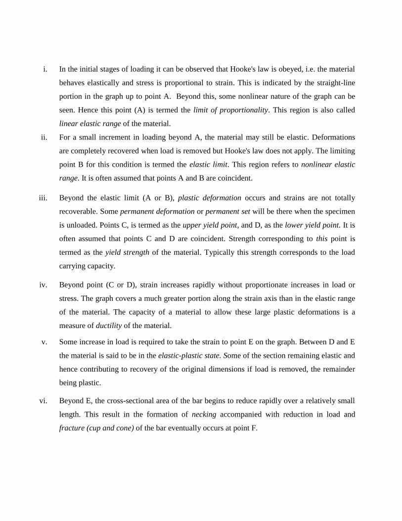
i. In the initial stages of loading it can be observed that Hooke's law is obeyed, i.e. the material
behaves elastically and stress is proportional to strain. This is indicated by the straight-line
portion in the graph up to point A. Beyond this, some nonlinear nature of the graph can be
seen. Hence this point (A) is termed the limit of proportionality. This region is also called
linear elastic range of the material.
ii. For a small increment in loading beyond A, the material may still be elastic. Deformations
are completely recovered when load is removed but Hooke's law does not apply. The limiting
point B for this condition is termed the elastic limit. This region refers to nonlinear elastic
range. It is often assumed that points A and B are coincident.
iii. Beyond the elastic limit (A or B), plastic deformation occurs and strains are not totally
recoverable. Some permanent deformation or permanent set will be there when the specimen
is unloaded. Points C, is termed as the upper yield point, and D, as the lower yield point. It is
often assumed that points C and D are coincident. Strength corresponding to this point is
termed as the yield strength of the material. Typically this strength corresponds to the load
carrying capacity.
iv. Beyond point (C or D), strain increases rapidly without proportionate increases in load or
stress. The graph covers a much greater portion along the strain axis than in the elastic range
of the material. The capacity of a material to allow these large plastic deformations is a
measure of ductility of the material.
v. Some increase in load is required to take the strain to point E on the graph. Between D and E
the material is said to be in the elastic-plastic state. Some of the section remaining elastic and
hence contributing to recovery of the original dimensions if load is removed, the remainder
being plastic.
vi. Beyond E, the cross-sectional area of the bar begins to reduce rapidly over a relatively small
length. This result in the formation of necking accompanied with reduction in load and
fracture (cup and cone) of the bar eventually occurs at point F.

vii. The nominal stress at failure, termed the maximum or ultimate tensile stress, is given by the
load at E divided by the original cross-sectional area of the bar. This is also known as the
ultimate tensile strength of the material.
viii. Owing to the large reduction in area produced by the necking process the actual stress at
fracture is often greater than the ultimate tensile strength. Since, however, designers are
interested in maximum loads which can be carried by the complete cross-section, the stress at
fracture is not of any practical importance.
1.9 Influence of Repeated loading and unloading on yield strength
If load is removed from the test specimen after the yield
point C has been passed, e.g. to some position S, as
shown in the adjoining figure the unloading line ST
can, for most practical purposes, be taken to be linear.
A second load cycle, commencing with the permanent
elongation associated with the strain OT, would then
follow the line TS and continue along the previous
curve to failure at F. It can be observed, that the repeated load cycle has the effect of increasing
the elastic range of the material, i.e. raising the effective yield point from C to S. However, it is
important to note that the tensile strength is unaltered. The procedure could be repeated along the
line PQ, etc., and the material is said to have been work hardened. Repeated loading and
unloading will produce a yield point approaching the ultimate stress value but the elongation or
strain to failure will be very much reduced.
1.10 Non Ferrous metals
Typical stress-strain curves resulting from tensile
tests on other engineering materials are shown in
the following figure.
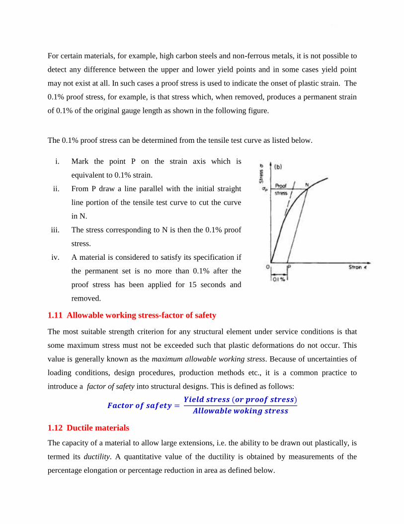
For certain materials, for example, high carbon steels and non-ferrous metals, it is not possible to
detect any difference between the upper and lower yield points and in some cases yield point
may not exist at all. In such cases a proof stress is used to indicate the onset of plastic strain. The
0.1% proof stress, for example, is that stress which, when removed, produces a permanent strain
of 0.1% of the original gauge length as shown in the following figure.
The 0.1% proof stress can be determined from the tensile test curve as listed below.
i. Mark the point P on the strain axis which is
equivalent to 0.1% strain.
ii. From P draw a line parallel with the initial straight
line portion of the tensile test curve to cut the curve
in N.
iii. The stress corresponding to N is then the 0.1% proof
stress.
iv. A material is considered to satisfy its specification if
the permanent set is no more than 0.1% after the
proof stress has been applied for 15 seconds and
removed.
1.11 Allowable working stress-factor of safety
The most suitable strength criterion for any structural element under service conditions is that
some maximum stress must not be exceeded such that plastic deformations do not occur. This
value is generally known as the maximum allowable working stress. Because of uncertainties of
loading conditions, design procedures, production methods etc., it is a common practice to
introduce a factor of safety into structural designs. This is defined as follows:
( )
1.12 Ductile materials
The capacity of a material to allow large extensions, i.e. the ability to be drawn out plastically, is
termed its ductility. A quantitative value of the ductility is obtained by measurements of the
percentage elongation or percentage reduction in area as defined below.

Note:
A property closely related to ductility is malleability, which defines a material's ability to be hammered out into thin
sheets. Malleability thus represents the ability of a material to allow permanent extensions in all lateral directions
under compressive loadings.
1.13 Brittle materials
A brittle material is one which exhibits relatively small extensions
to fracture so that the partially plastic region of the tensile test
graph is much reduced. There is little or no necking at fracture for
brittle materials. Typical tensile test curve for a brittle material
could well look like the one shown in the adjoining figure.
1.14 Lateral strain and Poisson’s ratio
Till now we have focused on the longitudinal strain induced in the direction of application of the
load. It has been observed that deformations also take place in the lateral direction. Consider the
rectangular bar shown in the figure below and subjected to a tensile load.
Under the action of this load the bar will increase in length by an amount L giving a
longitudinal strain in the bar: L = L/L. The bar will also exhibit, however, a reduction in
dimensions laterally, i.e. its breadth and depth will both reduce. The associated lateral strains will
both be equal, and are of opposite sense to the longitudinal strain. These are computed as : lat =
b/b = d/d.

It has been observed that within the elastic range the ratio of the lateral and longitudinal strains
will always be constant. This ratio is termed Poisson's ratio ().
The above equation can also be written as :
For most of the engineering materials the value of is found to be between 0.25 and 0.33.
Example 1
A bar of a rectangular section of 20 mm × 30 mm and a length of 500 mm is subjected to an axial
compressive load of 60 kN. If E = 102 kN/mm2 and v = 0.34, determine the changes in the
length and the sides of the bar.
Since the bar is subjected to compression, there will be decrease in length, increase in
breadth and depth. These are computed as shown below
L = 500 mm, b = 20 mm, d = 30 mm, P = 60 x1000 = 60000 N, E = 102000 N/mm2
Cross-sectional area A = 20 × 30 = 600 mm2
Compressive stress = P/A = 60000/600 = 100 N/mm2
Longitudinal strain L = /E = 100/102000 = 0.00098
Lateral strain lat = L = 0.34 x 0.00098 = 0.00033
Decrease in length L = L L = 0.00098 x 500 = 0.49 mm
Increase in breadth b = lat b = 0.00033 x 20 = 0.0066 mm
Increase in depth d = lat d = 0.00033 x 30 = 0.0099 mm
Example 2
Determine the stress in each section of the bar shown in the following figure when subjected to
an axial tensile load of 20 kN. The central section is of square cross-section; the other portions
are of circular section. What will be the total extension of the bar? For the bar material E =
210000MPa.
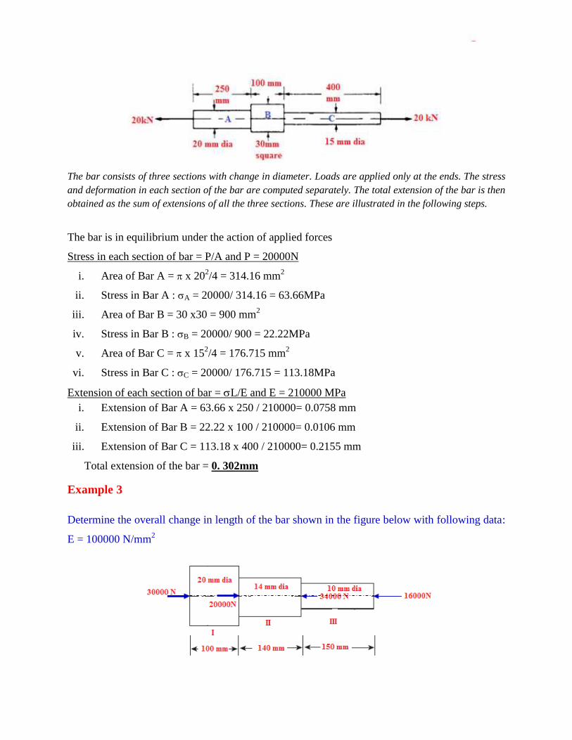
The bar consists of three sections with change in diameter. Loads are applied only at the ends. The stress
and deformation in each section of the bar are computed separately. The total extension of the bar is then
obtained as the sum of extensions of all the three sections. These are illustrated in the following steps.
The bar is in equilibrium under the action of applied forces
Stress in each section of bar = P/A and P = 20000N
i. Area of Bar A = x 202/4 = 314.16 mm
2
ii. Stress in Bar A : A = 20000/ 314.16 = 63.66MPa
iii. Area of Bar B = 30 x30 = 900 mm2
iv. Stress in Bar B : B = 20000/ 900 = 22.22MPa
v. Area of Bar C = x 152/4 = 176.715 mm
2
vi. Stress in Bar C : C = 20000/ 176.715 = 113.18MPa
Extension of each section of bar = L/E and E = 210000 MPa
i. Extension of Bar A = 63.66 x 250 / 210000= 0.0758 mm
ii. Extension of Bar B = 22.22 x 100 / 210000= 0.0106 mm
iii. Extension of Bar C = 113.18 x 400 / 210000= 0.2155 mm
Total extension of the bar = 0. 302mm
Example 3
Determine the overall change in length of the bar shown in the figure below with following data:
E = 100000 N/mm2

The bar is with varying cross-sections and subjected to forces at ends as well as at other interior
locations. It is necessary to study the equilibrium of each portion separately and compute the change in
length in each portion. The total change in length of the bar is then obtained as the sum of extensions of
all the three sections as shown below.
Forces acting on each portion of the bar for equilibrium
Sectional Areas
;
Change in length in Portion I
Portion I of the bar is subjected to an axial compression of 30000N. This results in decrease in
length which can be computed as
Change in length in Portion II
Portion II of the bar is subjected to an axial compression of 50000N ( 30000 + 20000). This
results in decrease in length which can be computed as
Change in length in Portion III
Portion III of the bar is subjected to an axial compression of (50000 – 34000) = 16000N. This
results in decrease in length which can be computed as

Since each portion of the bar results in decrease in length, they can be added without any
algebraic signs.
Hence Total decrease in length = 0.096 + 0.455 + 0.306 = 0.857mm
Note:
For equilibrium, if some portion of the bar may be subjected to tension and some other portion
to compression resulting in increase or decrease in length in different portions of the bar. In
such cases, the total change in length is computed as the sum of change in length of each portion
of the bar with proper algebraic signs. Generally positive sign (+) is used for increase in length
and negative sign (-) for decrease in length.
1.15 Elongation of tapering bars of circular cross section
Consider a circular bar uniformly tapered from diameter d1 at one end and gradually increasing
to diameter d2 at the other end over an axial length L as shown in the figure below.
Since the diameter of the bar is continuously changing, the elongation is first computed over an
elementary length and then integrated over the entire length. Consider an elementary strip of
diameter d and length dx at a distance of x from end A.
Using the principle of similar triangles the following equation for d can be obtained
Cross–sectional area of the bar at x : ( )
Axial stress at x:
( )
Change in length over dx :
( )

Total change in length: ∫
( )
[
( )
]
[
( )
]
[
( )
]
[
( )
]
( )
[ ]
[
]
Substituting for
in the above expression, following equation for elongation of
tapering bar of circular section can be obtained
Total change in length:
Example 4
A bar uniformly tapers from diameter 20 mm at one end to diameter 10 mm at the other end
over an axial length 300 mm. This is subjected to an axial compressive load of 7.5 kN. If E =
100 kN/mm2, determine the maximum and minimum axial stresses in bar and the total change
in length of the bar.
P = 7500 N, E = 100000 N/mm2 ,
d1 = 10mm, d2 = 20mm,L = 300mm
Minimum compressive stress occurs at d2 = 20mm as the sectional area is maximum.
Area at d2 =
Maximum compressive stress occurs at d1 = 10mm as the sectional area is minimum.
Area at d1 =
Total decrease in length:

1.16 Elongation of tapering bars of rectangular cross section
Consider a bar of same thickness t throughout its length, tapering uniformly from a breadth B at
one end to a breadth b at the other end over an axial length L. The flat is subjected to an axial
force P as shown in the figure below.
Since the breadth of the bar is continuously changing, the elongation is first computed over an
elementary length and then integrated over the entire length. Consider an elementary strip of
breadth bx and length dx at a distance of x from left end.
Using the principle of similar triangles the following equation for bx can be obtained
Cross–sectional area of the bar at x : ( )
Axial stress at x:
( )
Change in length over dx : ( )
Total change in length: ∫
( )
[ ( )]
[ ( ) ( )]
( )
[ ( ) ( )]
( ⁄ )
Substituting for
in the above expression, following equation for elongation of tapering
bar of rectangular section can be obtained
( ) ( ⁄ )

Example 5
An aluminium flat of a thickness of 8 mm and an axial length of 500 mm has a width of 15
mm tapering to 25 mm over the total length. It is subjected to an axial compressive force P, so
that the total change in the length of flat does not exceed 0.25 mm. What is the magnitude
of P, if E = 67,000 N/mm2 for aluminium?
t = 8mm, B = 25mm,b = 15mm, L = 500 mm, L = 0.25 mm, E = 67000MPa, P =?
( )
( ⁄ ) ( )
( ⁄ )
Note:
Instead of using the formula, this problem can be solved from first principles as indicated in
section 1.16.
1.17 Elongation in Bar Due to Self-Weight
Consider a bar of a cross-sectional area of A and a length L is
suspended vertically with its upper end rigidly fixed as shown in the
adjoining figure. Let the weight density of the bar is . Consider a
section y- y at a distance y from the lower end.
Weight of the portion of the bar below y-y = A y
Stress at y-y : y = A y /A = y
Strain at y-y : y = y / E
Change in length over dy: dy = y dy / E
Total change in length : ∫
[
]
This can also be written as : ( )
W = A L represents the total weight of the bar
Note:
The stress in the bar gradually increases linearly from zero at bottom
to L at top as shown below.

Example 6
A stepped steel bar is suspended vertically. The diameter in
the upper half portion is 10 mm, while the diameter in the
lower half portion is 6 mm. What are the stresses due to
self-weight in sections B and A as shown in the figure. E =
200 kN/mm2. Weight density, = 0.7644x10
-3 N/mm
3.
What is the change in its length if E = 200000 MPa?
Stress at B will be due to weight of portion of the bar BC
Sectional area of BC: A2 = x 62/4 = 28.27 mm
2
Weight of portion BC: W2 = A2 L2 = 0.7644x 10-3
x 28.27 x 1000 = 21.61N
Stress at B: B = W2/A2 = 21.61/28.27 = 0.764 MPa
Stress at A will be due to weight of portion of the bar BC + AB
Sectional area of AB: A1= x 102/4 = 78.54 mm
2
Weight of portion AB: W1 = A1 L1 = 0.7644x 10-3
x 78.54 x 1000 = 60.04N
Stress at A: c = (W1+W2)/A1 = (60.04+ 21.61) / 78.54 = 1.04 MPa
Change in Length in portion BC
This is caused due to weight of BC and is computed as:
= 0.00191mm
Change in Length in portion AB
This is caused due to weight of AB and due to weight of BC acting as a concentrated load at B
and is computed as:
0.0033mm
Total change in length = 0.00191+ 0.0033 = 0.00521mm
1.18 Saint Venant’s principle
In 1855, the French Elasticity theorist Adhemar Jean Claude Barre de Saint-Venant stated that
the difference between the effects of two different but statically equivalent loads becomes very
small at sufficiently large distances from the load. The stresses and strains in a body at points
that are sufficiently remote from points of application of load depend only on the static resultant
of the loads and not on the distribution of loads.

Stress concentration is the increase in stress along the cross-section that maybe caused by a point
load or by any another discontinuity such as a hole which brings about an abrupt change in the
cross sectional area.
In St.Venant‟s Principle experiment, we fix two strain gages, one near the central portion of the
specimen and one near the grips of the Universal Testing Machine‟s (UTM) upper (stationary)
holding chuck.. The respective strain values obtained from both the gages are measured and then
plotted with respect to time. Since stress is proportional to strain, as per St.Venant‟s principle,
the stress will be concentrated near the point of application of load. Although the average stress
along the uniform cross section remains constant, at the point of application of load, the stress is
distributed as shown in figure below with stress being concentrated at the load point. The further
the distance from the point of application of load, the more uniform the stress is distributed
across the cross section.
1.19 Compound or composite bars
A composite bar can be made of two bars of different materials rigidly fixed together so that both
bars strain together under external load. As the strains in the two bars are same, the stresses in
the two bars will be different and depend on their respective modulus of elasticity. A stiffer bar
will share major part of external load.
In a composite system the two bars of different materials may act as suspenders to a third rigid
bar subjected to loading. As the change in length of both bars is the same, different stresses are
produced in two bars.
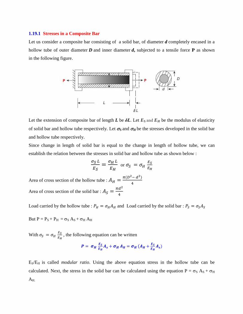
1.19.1 Stresses in a Composite Bar
Let us consider a composite bar consisting of a solid bar, of diameter d completely encased in a
hollow tube of outer diameter D and inner diameter d, subjected to a tensile force P as shown
in the following figure.
Let the extension of composite bar of length L be δL. Let ES and EH be the modulus of elasticity
of solid bar and hollow tube respectively. Let S and H be the stresses developed in the solid bar
and hollow tube respectively.
Since change in length of solid bar is equal to the change in length of hollow tube, we can
establish the relation between the stresses in solid bar and hollow tube as shown below :
or
Area of cross section of the hollow tube : ( )
Area of cross section of the solid bar :
Load carried by the hollow tube : and Load carried by the solid bar :
But P = PS + PH = S AS + H AH
With
, the following equation can be written
(
)
ES/EH is called modular ratio. Using the above equation stress in the hollow tube can be
calculated. Next, the stress in the solid bar can be calculated using the equation P = S AS + H
AH.

Example 7
A flat bar of steel of 24 mm wide and 6 mm thick is placed between two aluminium alloy flats 24
mm × 9 mm each. The three flats are fastened together at their ends. An axial tensile load of 20
kN is applied to the composite bar. What are the stresses developed in steel and aluminium
alloy? Assume ES = 210000 MPa and EA = 70000MPa.
Area of Steel flat: AS = 24 x 6 = 144 mm2
Area of Aluminium alloy flats: AA = 2 x 24 x 9 = 432 mm
2
Since all the flats elongate by the same extent, we have the condition that
.
The relationship between the stresses in steel and aluminum flats can be established as:
Since P = PS + PA = S AS + A AA . This can be written as
( )
From which stress in aluminium alloy flat can be computed as:
( )
( )
Stress in steel flat can be computed as:

Example 8
A short post is made by welding steel plates into a
square section and then filling inside with concrete. The
side of square is 200 mm and the thickness t = 10 mm
as shown in the figure. The steel has an allowable stress
of 140 N/mm2 and the concrete has an allowable stress
of 12 N/mm2. Determine the allowable safe
compressive load on the post. EC = 20 GPa, Es = 200
GPa.
Since the composite post is subjected to compressive load, both concrete and steel tube will
shorten by the same extent. Using this condition following relation between stresses in concrete
and steel can be established.
or
Assume that load is such that s = 140 N/mm2. Using the above relationship, the stress in
concrete corresponding to this load can be calculated as follows:
> 12 N/mm
2
Hence the assumed load is not a safe load.
Instead assume that load is such that c = 12 N/mm2. The stress in steel corresponding to this
load can be calculated as follows:
< 140 N/mm
2
Hence the assumed load is a safe load which is calculated as shown below.
Area of concrete section Ac = 180 x180 = 32400mm2.
Area of steel tube As = 200 x 200 – 32400 = 7600 mm2.

Example 9
A rigid bar is suspended from two wires, one of steel and other of copper, length of the wire is
1.2 m and diameter of each is 2.5 mm. A load of 500 N is suspended on the rigid bar such that
the rigid bar remains horizontal. If the distance between the wires is 150 mm, determine the
location of line of application of load. What are the stresses in each wire and by how much
distance the rigid bar comes down? Given Es = 3Ecu= 201000 N/mm2.
i. Area of copper wire (Acu) = Area of steel wire(As) = x 2.52/4 = 4.91 mm
2
ii. For the rigid bar to be horizontal, elongation of both the wires must be same. This condition
leads to the following relationship between stresses in steel and copper wires as:
iii. Using force equilibrium, the stress in copper and steel wire can be calculated as:
P = Ps + Pcu = s As + cu Acu = 3 cu As + cu Acu = cu (3As + Acu)
( )
( )
iv. Downward movement of rigid bar = elongation of wires

v. Position of load on the rigid bar is computed by equating moments of forces carried by steel and
copper wires about the point of application of load on the rigid bar.
( )
( ) ( ) ( )
Note:
If the load is suspended at the centre of rigid bar, then both steel and copper wire carry the same
load. Hence the stress in the wires is also same. As the moduli of elasticity of wires are different,
strains in the wires will be different. This results in unequal elongation of wires causing the rigid
bar to rotate by some magnitude. This can be prevented by offsetting the load or with wires
having different length or with different diameter such that elongation of wires will be same.
Example 10
A load of 2MN is applied on a column 500mm x 500mm. The column is reinforced with four
steel bars of 12mm dia, one in each corner. Find the stresses in concrete and steel bar. Es = 2.1
x105 N/mm
2 and Ec = 1.4 x 10
4 N/mm
2.
i. Area of steel bars: As= 4 x ( x 122/4) = 452.4 mm
2
ii. Area of concrete: Ac = 500 x500 – 452.4 = 249547.6 mm2
iii. Relation between stress in steel and concrete :
iv. P = Ps + Pc = s As + c Ac = 15 c As + c Ac = c (15As + Ac)
v.
( )
( )
vi.

1.20 Temperature stresses in a single bar
If a bar is held between two unyielding (rigid) supports and its temperature is raised, then a
compressive stress is developed in the bar as its free thermal expansion is prevented by the rigid
supports. Similarly, if its temperature is reduced, then a tensile stress is developed in the bar as
its free thermal contraction is prevented by the rigid supports. Let us consider a bar of
diameter d and length L rigidly held between two supports as shown in the following figure. Let
α be the coefficient of linear expansion of the bar and its temperature is raised by ∆T (°C)
Free thermal expansion in the bar = α ∆T L.
Since the supports are rigid, the final length of the bar does not change. The fixed ends
exert compressive force on the bar so as to cause shortening of the bar by α ∆T L.
Hence the compressive strain in the bar = α ∆T L / L = α ∆T
Compressive stress = α ∆T E
Hence the thermal stresses introduced in the bar = α ∆T E
Note:
The bar can buckle due to large compressive forces generated in the bar due to temperature
increase or may fracture due to large tensile forces generated due to temperature decrease.
Example 11
A rail line is laid at an ambient temperature of 30°C. The rails are 30 m long and there is a
clearance of 5 mm between the rails. If the temperature of the rail rises to 60°C, what is the stress
developed in the rails?. Assume α = 11.5 × 10⁻⁶/°C, E = 2,10,000 N/mm
2
L = 30,000 mm, α = 11.5 × 10
−6/°C, Temperature rise ∆T = 60-30 = 30
oC
Free expansion of rails = α ∆T L = 11.5 × 10−6 × 30 × 30000 = 10.35mm
Thermal expansion prevented by rails = Free expansion – clearance = 10.35 – 5 = 5.35mm
Strain in the rails = 5.35/30000 = 0.000178
Compressive stress in the rails = x E = 0.000178 x 210000 =37.45N/mm2.
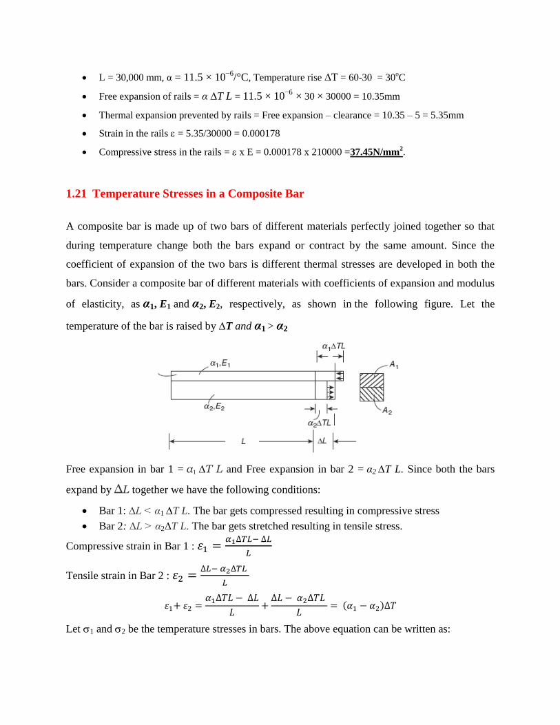
1.21 Temperature Stresses in a Composite Bar
A composite bar is made up of two bars of different materials perfectly joined together so that
during temperature change both the bars expand or contract by the same amount. Since the
coefficient of expansion of the two bars is different thermal stresses are developed in both the
bars. Consider a composite bar of different materials with coefficients of expansion and modulus
of elasticity, as α1, E1 and α2, E2, respectively, as shown in the following figure. Let the
temperature of the bar is raised by ∆T and α1 > α2
Free expansion in bar 1 = α1 ∆T L and Free expansion in bar 2 = α2 ∆T L. Since both the bars
expand by ∆L together we have the following conditions:
Bar 1: ∆L < α1 ∆T L. The bar gets compressed resulting in compressive stress
Bar 2: ∆L > α2∆T L. The bar gets stretched resulting in tensile stress.
Compressive strain in Bar 1 :
Tensile strain in Bar 2 :
( )
Let 1 and 2 be the temperature stresses in bars. The above equation can be written as:

( )
In the absence of external forces, for equilibrium, compressive force in Bar 1 = Tensile force in
Bar 2. This condition leads to the following relation
Using the above two equations, temperature stresses in both the bars can be computed. This is
illustrated in the following example.
Note:
If the temperature of the composite bar is reduced, then a tensile stress will be developed in bar
1 and a compressive stress will be developed in bar 2 , since α1 > α2.
Example 12
A steel flat of 20 mm × 10 mm is fixed with aluminium flat of 20 mm × 10 mm so as to make a
square section of 20 mm × 20 mm. The two bars are fastened together at their ends at a
temperature of 26°C. Now the temperature of whole assembly is raised to 55°C. Find the stress
in each bar. Es = 200 GPa, Ea = 70 GPa, αs = 11.6 × 10⁻⁶
/°C, αa = 23.2 × 10⁻⁶
/°C.
Net temperature rise, ∆T = 55 − 26 = 29°C.
Area of Steel flat (As) = Area of Aluminium flat (Aa) = 20 x10 =200 mm2
will be one of the conditions to be
satisfied by the composite assembly.
( ) ( )
( ) ( ) as αa > αs
Example 13
A flat steel bar of 20 mm × 8 mm is placed between two copper bars of 20 mm × 6 mm each so
as to form a composite bar of section of 20 mm × 20 mm. The three bars are fastened together at
their ends when the temperature of each is 30°C. Now the temperature of the whole assembly is

raised by 30°C. Determine the temperature stress in the steel and copper bars. Es = 2Ecu= 210
kN/mm2, αs = 11 × 10
−6/°C, αcu = 18 × 10
−6/°C.
Net temperature rise, ∆T = 30°C.
Area of Steel flat (As) = 20 x 8 = 160 mm2
Area of Copper flats (Acu) = 2 x 20 x 6 =240 mm2
will be one of the conditions to be
satisfied by the composite assembly.
( ) ( )
cu = 12.6MPa (compressive) and s = 18.9MPa (tensile) as αcu > αs
1.22 Simple Shear stress and Shear Strain
Consider a rectangular block which is fixed at the bottom and a force F is applied on the top
surface as shown in the figure (a) below.
Equal and opposite reaction F develops on the bottom plane and constitutes a couple, tending to
rotate the body in a clockwise direction. This type of shear force is a positive shear force and the
shear force per unit surface area on which it acts is called positive shear stress (). If force is
applied in the opposite direction as shown in Figure (b), then they are termed as negative shear
force and shear stress.
The Shear Strain () = AA‟/AD = tan. Since is a very small quantity, tan . Within the
elastic limit, or = G
The constant of proportionality G is called rigidity modulus or shear modulus.

Note:
Normal stress is computed based on area perpendicular to the surface on which the force is
acting, while, the shear stress is computed based on the surface area on which the force is
acting. Hence shear stress is also called tangential stress.
1.23 Complementary Shear Stresses
Consider an element ABCD subjected to shear stress () as shown in figure (a). We cannot have
equilibrium with merely equal and opposite tangential forces on the faces AB and CD as these
forces constitute a couple and induce a turning moment. The statical equilibrium demands that
there must be tangential components (‟) along AD and CB such that that can balance the
turning moment. These tangential stresse (‟) is termed as complimentary shear stress.
Let t be the thickness of the block. Turning moment due to will be ( x t x LAB ) LBC and
Turning moment due to ’ will be (‟ x t x LBC ) LAB. Since these moments have to be equal for
equilibrium we have:
( x t x LAB ) LBC = (‟ x t x LBC ) LAB.
From which it follows that = ‟ , that is, intensities of shearing stresses across two mutually
perpendicular planes are equal.
1.24 Volumetric strain
This refers to the slight change in the volume of the body resulting from three mutually
perpendicular and equal direct stresses as in the case of a body immersed in a liquid under
pressure. This is defined as the ratio of change in volume to the original volume of the body.
Consider a cube of side „a‟ strained so that each side becomes „a a’.
Hence the linear strain = a/a.
Change in volume = (a a)3 –a
3 = 3a
2a. (ignoring small higher order terms)
Volumetric strain v = 3a2 a/a
3 = 3 a/a
The volumetric strain is three times the linear strain
1.25 Bulk Modulus
This is defined as the ratio of the normal stresses (p) to the volumetric strain (v) and denoted by
‘K’. Hence K = p/v . This is also an elastic constant of the material in addition to E, G and .
1.26 Relation between elastic constants
1.26.1 Relation between E,G and
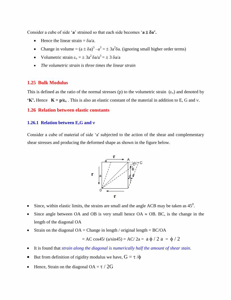
Consider a cube of material of side „a' subjected to the action of the shear and complementary
shear stresses and producing the deformed shape as shown in the figure below.
Since, within elastic limits, the strains are small and the angle ACB may be taken as 450.
Since angle between OA and OB is very small hence OA OB. BC, is the change in the
length of the diagonal OA
Strain on the diagonal OA = Change in length / original length = BC/OA
= AC cos45/ (a/sin45) = AC/ 2a = a / 2 a = / 2
It is found that strain along the diagonal is numerically half the amount of shear stain.
But from definition of rigidity modulus we have, G = /
Hence, Strain on the diagonal OA = / 2G

The shear stress system is equivalent or can be replaced by a system of direct stresses at 45
0 as
shown below. One set will be compressive, the other tensile, and both will be equal in value to
the applied shear stress.
Strain in diagonal OA due to direct stresses =
( )
Equating the strain in diagonal OA we have
( )
Relation between E,G and can be expressed as : ( )
1.26.2 Relation between E,K and
Consider a cube subjected to three equal stresses a shown in the figure below.
Strain in any one direction =
( )
Since the volumetric strain is three times the linear strain: ( )
From definition of bulk modulus :
( )
Relation between E,K and can be expressed as : ( )
Note: Theoretically < 0.5 as E cannot be zero
1.26.3 Relation between E, G and K
We have E = 2G(1+) from which = (E - 2G) / 2G
We have E = 3K(1-2) from which = (3K -E) / 6K
(E - 2G) / 2G = (3K -E) / 6K or (6EK - 12GK) = (6GK - 2EG) or 6EK+2EG = (6GK +12GK)
Relation between E,G and K can be expressed as:
( )
1.27 Exercise problems
1. A steel bar of a diameter of 20 mm and a length of 400 mm is subjected to a tensile force of
40 kN. Determine (a) the tensile stress and (b) the axial strain developed in the bar if the
Young‟s modulus of steel E = 200 kN/mm2
Answer: (a) Tensile stress = 127.23MPa, (b) Axial strain = 0.00064
2. A 100 mm long bar is subjected to a compressive force such that the stress developed in the
bar is 50 MPa. (a) If the diameter of the bar is 15 mm, what is the axial compressive force?
(b) If E for bar is 105 kN/mm2, what is the axial strain in the bar?
Answer: (a) Compressive force = 8.835 kN, (b) Axial strain = 0.00048
3. A steel bar of square section 30 × 30 mm and a length of 600 mm is subjected to an axial
tensile force of 135 kN. Determine the changes in dimensions of the bar. E = 200
kN/mm2, v = 0.3.
Answer: Increase in length δl = 0.45 mm, Decrease in breadth δb = 6.75 × 10⁻³
mm,
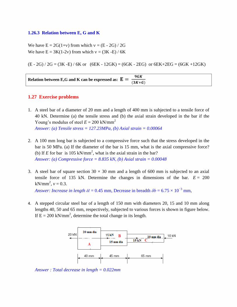
4. A stepped circular steel bar of a length of 150 mm with diameters 20, 15 and 10 mm along
lengths 40, 50 and 65 mm, respectively, subjected to various forces is shown in figure below.
If E = 200 kN/mm2, determine the total change in its length.
Answer : Total decrease in length = 0.022mm

5. A stepped bar is subjected to axial loads as shown in the figure below. If E = 200 GPa,
calculate the stresses in each portion AB, BC and CD. What is the total change in length of
the bar?
Answer: Total increase in length = 0.35mm
6. A 400-mm-long aluminium bar uniformly tapers from a diameter of 25 mm to a diameter of
15 mm. It is subjected to an axial tensile load such that stress at middle section is 60 MPa.
What is the load applied and what is the total change in the length of the bar if E = 67,000
MPa? (Hint: At the middle diameter = (25+15)/2 = 20 mm).
Answer: Load = 18.85kN, Increase in length = 0.382 mm
7. A short concrete column of 250 mm × 250 mm in section strengthened by four steel bars near
the corners of the cross-section. The diameter of each steel bar is 30 mm. The column is
subjected to an axial compressive load of 250 kN. Find the stresses in the steel and the
concrete. Es = 15 Ec = 210 GPa. If the stress in the concrete is not to exceed 2.1 N/mm2,
what area of the steel bar is required in order that the column may support a load of 350 kN?
Answer: Stress in concrete = 2.45N/mm2, Stress in steel = 36.75N/mm2, Area of steel = 7440 mm
2
8. Two aluminium strips are rigidly fixed to a steel strip of section 25 mm × 8 mm and 1 m
long. The aluminium strips are 0.5 m long each with section 25 mm × 5 mm. The composite
bar is subjected to a tensile force of 10 kN as shown in the figure below. Determine the
deformation of point B. Es = 3EA = 210 kN/mm2. Answer: 0.203mm
(Hint: Portion CB is a single bar, Portion AC is a composite bar. Compute elongation
separately for both the portions and add)