st.martins engineering collegesmec.ac.in/sites/default/files/courses_description/switch gear...
TRANSCRIPT
ST.MARTINS ENGINEERING COLLEGE ELECTRICAL AND ELECTRONICS ENGINEERING
Dhulapally, Secunderabad – 500014.
COURSE OBJECTIVES
Academic Year : 2016-2017
Semester : I / II
Name of the Program: B.Tech EEE Year: IV Section: A
Course/Subject: Switch Gear and Protection Course Code: A70231
Name of the Faculty: Babita Nanda Dept.: EEE
Designation: ASSOCIATE PROFESSOR
On completion of this Subject/Course the student shall be able to:
S.No Objectives
1
To introduce students to power system protection and switchgear.
2
To teach students theory and applications of the main components used in power system
protection for electric machines, transformers, bus bars, overhead and underground feeders.
3 To teach students the theory, construction, applications of main types Circuit breakers, Relays
for protection of generators, transformers and protection of feeders from over- voltages and
other hazards. It emphasis on neutral grounding for overall protection
4 To develop an ability and skill to design the feasible protection systems needed for each main
part of a power system in students.

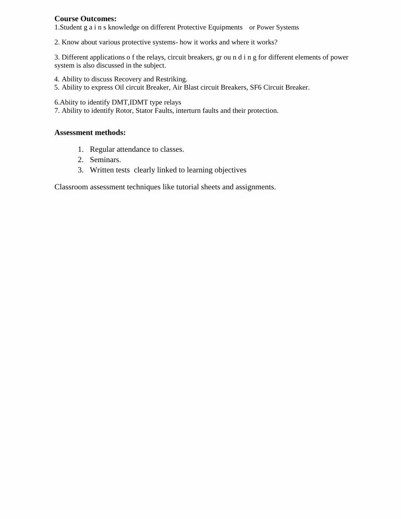
COURSE OUTCOMES
S.No Outcomes
1.Student g a i n s knowledge on different Protective Equipments or Power Systems
2. Know about various protective systems- how it works and where it works?
3. Different applications o f the relays, circuit breakers, gr ou n d i n g for different elements of power system is also discussed in the subject.
4. Ability to discuss recovery and Restriking. 5. Ability to express Oil circuit Breaker, Air Blast circuit Breakers, SF6 Circuit Breaker.
6.Abiity to identify DMT,IDMT type relays 7. Ability to identify Rotor, Stator Faults, inter turn faults and their protection.
Name of the Course: SwitchGear&Protection
Course Objectives:
1. To introduce students to power system protection and switchgear.
2. To teach students theory and applications of the main components used in power system
protection for electric machines, transformers, bus bars, overhead and underground feeders.
3. To teach students the theory, construction, applications of main types Circuit breakers, Relays
for protection of generators, transformers and protection of feeders from over- voltages and
other hazards. It emphasis on neutral grounding for overall protection
4. To develop an ability and skill to design the feasible protection systems needed for each main
part of a power system in students.
Course Outcomes: 1.Student g a i n s knowledge on different Protective Equipments or Power Systems
2. Know about various protective systems- how it works and where it works?
3. Different applications o f the relays, circuit breakers, gr ou n d i n g for different elements of power system is also discussed in the subject.
4. Ability to discuss Recovery and Restriking. 5. Ability to express Oil circuit Breaker, Air Blast circuit Breakers, SF6 Circuit Breaker.
6.Abiity to identify DMT,IDMT type relays 7. Ability to identify Rotor, Stator Faults, interturn faults and their protection.
Assessment methods:
1. Regular attendance to classes. 2. Seminars. 3. Written tests clearly linked to learning objectives
Classroom assessment techniques like tutorial sheets and assignments.
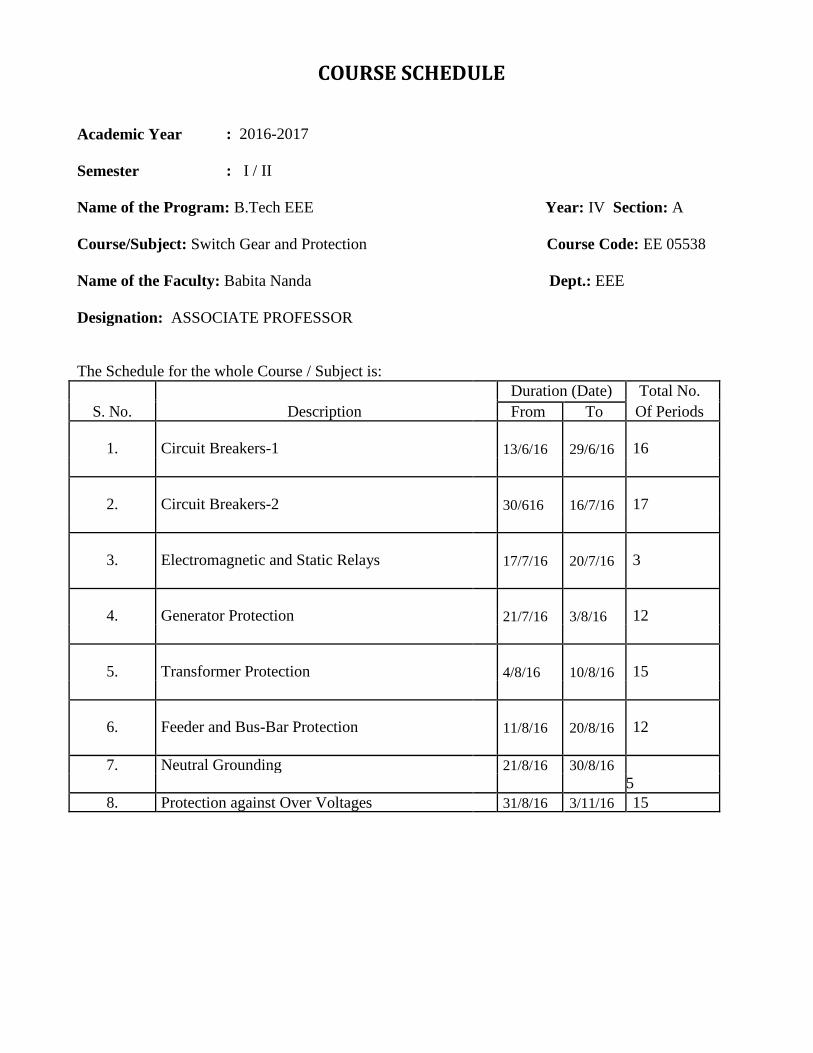
COURSE SCHEDULE
Academic Year : 2016-2017
Semester : I / II
Name of the Program: B.Tech EEE Year: IV Section: A
Course/Subject: Switch Gear and Protection Course Code: EE 05538
Name of the Faculty: Babita Nanda Dept.: EEE
Designation: ASSOCIATE PROFESSOR
The Schedule for the whole Course / Subject is:
Duration (Date) Total No.
S. No. Description
Of Periods From To
1. Circuit Breakers-1 13/6/16 29/6/16 16
2. Circuit Breakers-2 30/616 16/7/16 17
3. Electromagnetic and Static Relays 17/7/16 20/7/16 3
4. Generator Protection 21/7/16 3/8/16 12
5. Transformer Protection 4/8/16 10/8/16 15
6. Feeder and Bus-Bar Protection 11/8/16 20/8/16 12
7. Neutral Grounding 21/8/16 30/8/16
5
8. Protection against Over Voltages 31/8/16 3/11/16 15

SUGGESTED BOOKS:
TEXT BOOKS:
T1: Sunil S Rao “Switchgear Protection & Power Systems” , Khanna Publlishers
T2: Badari Ram & D.N Viswakarma “Power System Protection and Switchgear” , TMH
publications
REFERENCES BOOKS :
R1: Paithankar and S.R.Bhide, “Fundamentals of Power System Protection”, PHI, 2003.
R2: T S Madhav Rao, “Power System Protection : Static Relays”, Tata McGraw-Hill, 2nd edition
R3: C R Mason, “Art & Science of Protective Relaying”, Wiley Eastern Ltd.
R4: Cl Wadhwa, “Electrical Power Systems”, New Age international (P) Limited, Publishers, 3rd
editon
R5: “Hand Book of Switchgears by BHEL”, TMH Publications.
No. of Objectives & References
Unit Date Periods Topics / Sub-Topics Outcomes (Text Book, Journal…)
No. Nos. Page Nos.: ____to ____
Elementary principles of arc 1, 3 & T1:3.7,4.8
I
13-Jun-
2016 1 interruption Circuit Breakers 1,2,3 T2:9.2, 9.3 Recovery, Restriking Voltage R4:15.2
and Recovery voltages R6:13.6, 14.3
Restriking Phenomenon, 2, 3 & 1,2, T1:3.10,3.19
I 1 Average and Max. RRRV, T2: 9.3
15-Jun-2016 Numerical Problems on R4:15.2
Recovery, Restriking Voltage R6:14.4, 14.5
and RRRV
Current chopping and 2, 3 & 1,2, T1:3.6,3.18,3.19
I 1 Resistance switching, CB T2: 9.5,9.6,9.16 ratings and Specifications: R4:15.3,15.9,15.11
16-Jun-2016
Types and Numerical R6:7.3,14.2,14.3 14.7
Problems. – Auto reclosures
Description and Operation of 2, 3 & 1,2,3 T1:6.2,8.3
II
17-Jun-
2016 1 Minimum Oil Circuit breakers, T2: 9.7,9.8,9.9,9.10
Description and Operation of R4:15.4,15.6
Air Blast Circuit Breakers R6:15.3,15.5
Description and Operation of 2, 3 & 1,2,3 T1:7.5,9.4
II 1 Vacuum circuit breakers, T2:
Description and Operation of 9.11,9.12,9.13,9.14,9.15
18-Jun-2016 SF6 circuit breakers R4:15.7,15.8
R6:16.2,16.3
Principle of Operation and 2, 3 & 1,2,3 T1:26.9,26.10
III 19/6 1 Construction of Attracted T2: 2.1 armature relays, Principle of R2:1.1 Operation and Construction of R4:14.4 Balanced Beam relays R6:3.2

Principle of Operation and 2, 3 & 1,2,3 T1: 26.10,26.12 III 20/6 1 Construction of induction Disc T2: 2.1
R2:1.6 relays, Principle of Operation
R4:14.4 21/6
and Construction of Induction
R6:3.2
Cup relays
Relays Classification: 2, 3 & 1,2,3 T1: 27.4,27.19 III 1 Instantaneous, DMT and IDMT T2: 3.4,3.5
R2:4.2,6.4 21/6 types, Over current/ Under
R4:14.5
voltage relays
R6:4.4,4.5
Direction relays, Differential 2, 3 & 1,2,3 T2 : 3.10,3.11
III 22/6 1 Relays T1 : 27.10,28.1
R2 : 7.2,7.3
R4 : 14.8,14.12
R6 : 4.7,4.9
Percentage Differential Relays. 2, 3 & 1,2,3 T2 : 3.11 III 23/6 1 T1 : 28.1
R2 : 7.3 R4 : 14.12
R6 : 4.9
Impedance, Reactance relays 2, 3 & 1,2,3 T2 : 4.1,4.2 III 24/6 1 T1 : 29.6,29.8
R4 : 14.7,14.10
R6 : 3.3
Mho and Off-Set Mho relays 2, 3 & 1,2,3 T2 : 4.3 III 25/6 1 T1 : 29.9
R4 : 14.7,14.10
R6 : 3.3
Characteristics of Distance 2, 3 & 1,2,3 T2 : 4.5 to 4.20, III 1 Relays and Comparison. T1 : 29.10
R2 : 8.6
R4 : 14.16
R6 : 4.8
Static Relays: Static Relays 2, 3 & 1,2,3 T2 : 2.3, 3.12 III 1 verses Electromagnetic Relays. R2 : 1.4
R6 : 12.1,12.4
Numerical Problems 1, 3 & 1,2,3
III 1
Protection of generators 2, 3 & 1,2,3 T2 : 6.1
IV 1 against Stator faults , T1 : 33.2,33.8
R2 : 16.3 Protection of generators
R4 : 14.11
against Rotor faults
R6 : 6.3
Protection of generators 2, 3 & 1,2,3 T2 : 6.1
IV 1 against Abnormal Conditions.. T1 : 33.12
R2 : 16.3
R4 : 14.11
R6 : 6.3
Restricted Earth fault and 2, 3 & 1,2,3 T2 : 3.8,3.9
IV 1 Inter-turn fault Protection, T1 : 33.2,33.4,33.7
R2 : 11.13,16.3 Numerical Problems on %
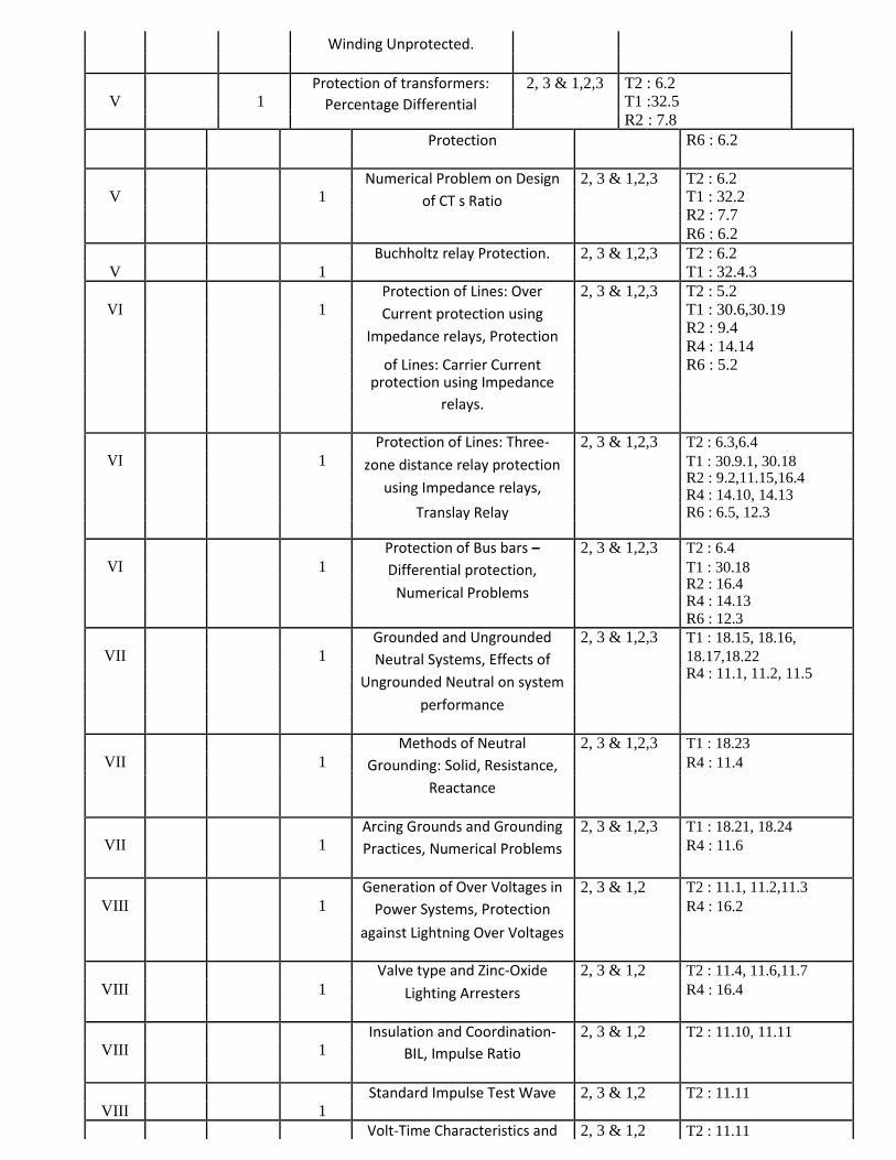
Winding Unprotected.
Protection of transformers: 2, 3 & 1,2,3 T2 : 6.2 V 1 Percentage Differential T1 :32.5
R2 : 7.8
Protection R6 : 6.2
Numerical Problem on Design 2, 3 & 1,2,3 T2 : 6.2 V 1 of CT s Ratio T1 : 32.2
R2 : 7.7
R6 : 6.2
Buchholtz relay Protection. 2, 3 & 1,2,3 T2 : 6.2
V 1 T1 : 32.4.3
Protection of Lines: Over 2, 3 & 1,2,3 T2 : 5.2 VI 1 Current protection using T1 : 30.6,30.19
R2 : 9.4 Impedance relays, Protection
R4 : 14.14
of Lines: Carrier Current
R6 : 5.2 protection using Impedance
relays.
Protection of Lines: Three- 2, 3 & 1,2,3 T2 : 6.3,6.4
VI 1 zone distance relay protection T1 : 30.9.1, 30.18
R2 : 9.2,11.15,16.4 using Impedance relays,
R4 : 14.10, 14.13
Translay Relay R6 : 6.5, 12.3
Protection of Bus bars – 2, 3 & 1,2,3 T2 : 6.4
VI 1 Differential protection, T1 : 30.18
R2 : 16.4 Numerical Problems
R4 : 14.13
R6 : 12.3
Grounded and Ungrounded 2, 3 & 1,2,3 T1 : 18.15, 18.16,
VII 1 Neutral Systems, Effects of 18.17,18.22
R4 : 11.1, 11.2, 11.5 Ungrounded Neutral on system
performance
Methods of Neutral 2, 3 & 1,2,3 T1 : 18.23
VII 1 Grounding: Solid, Resistance, R4 : 11.4
Reactance
Arcing Grounds and Grounding 2, 3 & 1,2,3 T1 : 18.21, 18.24
VII 1 Practices, Numerical Problems R4 : 11.6
Generation of Over Voltages in 2, 3 & 1,2 T2 : 11.1, 11.2,11.3
VIII 1 Power Systems, Protection R4 : 16.2
against Lightning Over Voltages
Valve type and Zinc-Oxide 2, 3 & 1,2 T2 : 11.4, 11.6,11.7
VIII 1 Lighting Arresters R4 : 16.4
Insulation and Coordination- 2, 3 & 1,2 T2 : 11.10, 11.11
VIII 1 BIL, Impulse Ratio
Standard Impulse Test Wave 2, 3 & 1,2 T2 : 11.11
VIII 1
Volt-Time Characteristics and 2, 3 & 1,2 T2 : 11.11

VIII 1 Insulation Co-ordination,
03-Nov-2016 Numerical Problems
SWITCHGEAR AND PROTECTION COURSE OBJECTIVE: “Switch Gear &Protection” subject gives general awareness of different Protective Equipments for Power Systems such as Relays, Circuit Breakers, and Isolators. It also explains about protective system- how it works and where it works? Different applications of the relays for different elements ofpower system is also discussed in the subject.
UNIT – I: Circuit Breakers - 1 Circuit Breakers: Elementary principles of arc interruption, Recovery, Restriking Voltage and Recoveryvoltages.- Restriking Phenomenon, Average and Max. RRRV, Numerical Problems. Current Chopping and Resistance Switching. CB ratings and Specifications : Types and Numerical Problems. – Autoreclosures.
UNIT –II: Circuit Breakers - 2 Description and Operation of following types of circuit breakers: Minimum Oil Circuit breakers, Air Blast Circuit Breakers, Vacuum and SF6 circuit breakers.
UNIT – III: Electromagnetic and Static Relays Principle of Operation and Construction of Attracted armature, Balanced Beam, induction Disc and Induction Cup relays. Relays Classification: Instantaneous, DMT and IDMT types. Application of relays: Over current/ Under voltage relays, Direction relays, Differential Relays and Percentage Differential Relays. Universal torque equation, Distance relays: Impedance, Reactance and Mho and Off-Set Mho relays, Characteristics of Distance Relays and Comparison. Static Relays: Static Relays verses Electromagnetic Relays.
UNIT – IV: Generator Protection Protection of generators against Stator faults, Rotor faults, and Abnormal Conditions. Restricted Earth fault and Inter-turn fault Protection. Numerical Problems on % Winding Unprotected.
UNIT –V: Transformer Protection Protection of transformers: Percentage Differential Protection, Numerical Problem on Design of CT s Ratio, Buchholtz relay Protection.
UNIT –VI: Feeder and Bus-Bar Protection Protection of Lines: Over Current, Carrier Current and Three-Zone distance relay protection using

Impedance relays. Translay Relay. Protection of Bus bars – Differential protection.
UNIT – VII: Neutral Grounding
Grounded and Ungrounded Neutral Systems.- Effects of Ungrounded Neutral on system
performance.Methods of Neutral Grounding: Solid, Resistance, Reactance –Arcing Grounds and Grounding Practices.
UNIT – VIII: Protection against over voltages Generation of Over Voltages in Power Systems.-Protection Against Lightning Over Voltages – Valve type
and Zinc-Oxide Lighting Arresters. Insulation and Coordination -BIL, Impulse Ratio,Standard Impulse Test
Wave, Volt-Time Characteristics and Insulation Co-ordination.
SUGGESTED BOOKS : TEXT BOOKS : T1: Sunil S Rao “Switchgear Protection & Power Systems” , Khanna Publlishers T2: Badari Ram & D.N Viswakarma “Power System Protection and Switchgear” , TMH publications
REFERENCES BOOKS :
R1: Paithankar and S.R.Bhide, “Fundamentals of Power System Protection”, PHI, 2003.
R2: T S Madhav Rao, “Power System Protection : Static Relays”, Tata McGraw-Hill, 2nd edition R3: C R Mason, “Art & Science of Protective Relaying”, Wiley Eastern Ltd.
R4: Cl Wadhwa, “Electrical Power Systems”, New Age international (P) Limited, Publishers, 3rdediton R5: “Hand Book of Switchgears by BHEL”, TMH Publications.
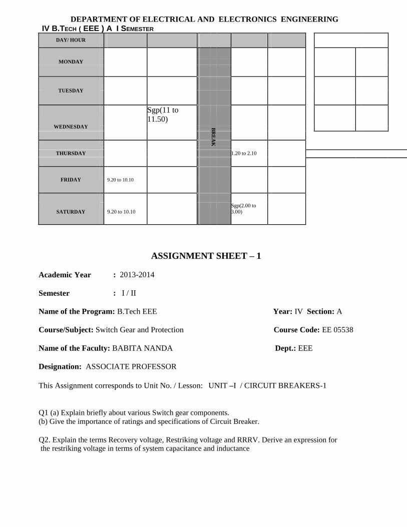
DEPARTMENT OF ELECTRICAL AND ELECTRONICS ENGINEERING
IV B.TECH ( EEE ) A I SEMESTER
DAY/ HOUR
MONDAY
TUESDAY
Sgp(11 to
11.50)
WEDNESDAY B
RE
AK
THURSDAY 1.20 to 2.10
FRIDAY 9.20 to 10.10
SATURDAY
9.20 to 10.10
Sgp(2.00 to
3.00)
ASSIGNMENT SHEET – 1
Academic Year : 2013-2014
Semester : I / II
Name of the Program: B.Tech EEE Year: IV Section: A
Course/Subject: Switch Gear and Protection Course Code: EE 05538
Name of the Faculty: BABITA NANDA Dept.: EEE
Designation: ASSOCIATE PROFESSOR
This Assignment corresponds to Unit No. / Lesson: UNIT –I / CIRCUIT BREAKERS-1
Q1 (a) Explain briefly about various Switch gear components.
(b) Give the importance of ratings and specifications of Circuit Breaker.
Q2. Explain the terms Recovery voltage, Restriking voltage and RRRV. Derive an expression for the restriking voltage in terms of system capacitance and inductance
Q3. Explain Slepian‟s theory of arc interruption and discuss its limitations. How does energy balance theory, explain the process of arc interruption?
ASSIGNMENT SHEET – 2
Designation: ASSOCIATE PROFESSOR
This Assignment corresponds to Unit No. / Lesson: UNIT –II / CIRCUIT BREAKERS-2
Q1 (a) Explain in detail the role of protective relays in a power systems.
(b) Discuss in detail the causes and types and frequency of faults encountered in a power system.
Q2. a) What are the necessary auxiliaries of ABCB? Describe compressed air system for supplying compressed air to the air blast circuit breakers?
(b) Explain current chopping in VCB. Explain the function of RC surge suppressors used with vacuum switchgear for motor switching
Please write the Questions / Problems / Exercises which you would like to give to the students and also mention the Objectives/Outcomes to which these Questions / Problems / Exercises are related.
ASSIGNMENT SHEET – 3
This Assignment corresponds to Unit No. / Lesson: UNIT –III / Electromagnetic and Static Relays
Q1 .With the help of neat sketch explain the principle of operation of Differential relays.
Q2. Distinguish between Over current relays, Directional relays and Differential relays. Q3
Define the following terms and explain their significance in distance protection
(a) Reach of a distance relay. (b) Under reach. 6. Explain the „Differential protection‟. State the various applications of differential
protection.
ASSIGNMENT SHEET – 4
This Assignment corresponds to Unit No. / Lesson: UNIT –IV / Generator Protection
Q1. Explain resistance switching in detail with relevant diagrams and derive the expression of damped oscillation.
Q2. (a) What is a direct connected generator? (b) Mention protective schemes for a direct connected generator. Explain any One of these schemes.
Q3.What are the types of faults that are likely to occur in an alternator? Explain a protection scheme against any one of these faults.
Q1. Describe the protection scheme for internal faults in a three phase delta/star connected power transformer. Draw a neat sketch and explain clearly why the CTs are to be connected in a particular fashion only.
Q2. What protective devices other than differential protection are used for the protection of a large transformer? Briefly describe them.
ASSIGNMENT SHEET – 6
This Assignment corresponds to Unit No. / Lesson: UNIT –VI / Feeder and Bus-Bar Protection
Q1 Describe the principle of bus bar protection based on voltage differential systems. How does it respond to saturation of CTs for external and internal faults?
Q2.Describe earth fault protection of sectionalized busbar.
Q3. Explain „High Impedance Differential Protection of Bus‟.

This Assignment corresponds to Unit No. / Lesson: UNIT –VII / Neutral Grounding
Q1. State the difference between equipment earthing and neutral earthing.
Q2. What are the merits and demerits of reactance earthing compared to solid earthing?
Q3. Explain the phenomenon of “arcing grounds” on overhead transmission lines. How does
neutral earthing oppose arcing ground currents?
Q4. Explain with diagrams : the phase to earth voltage rise in unfaulted lines during a single phase to earth fault in a 3-phase system without (a) neutral earhting, (b) the situation with neutral earthing.
ASSIGNMENT SHEET – 8
This Assignment corresponds to Unit No. / Lesson: UNIT –VIII / Protection against Over Voltages
Q1 .What are the causes of over-voltages arising on a power system? Why is it necessary to protect the lines and other equipment of power system against over voltages?
Q2. How can the magnitude of over voltages due to direct and indirect lightning strokes on overhead lines be calculated?
Q3. What is a ground wire? What are the requirements to be satisfied by ground wires to provide efficient protection to lines against direct lightening strokes? How do ground wires protect the overhead lines against direct lightening strokes?
Q4. Explain the term over voltage factor, protective ratio, protective angle, protective zone and coupling factor?
TUTOTIAL SHEET - 1
Q1. A three phase alternator of rated line to line voltage of 13.5KV is connected to a circuit breaker. The inductive reactance up to the circuit -breaker is 4 ohms per phase. The distributed capacitance up
to the circuit breaker between phases to neutral is 0.2μF. Determine the following neglecting
First Pole to clear factor.
Q2. Explain the arc extinction process in alternating circuit breaker. An electric arc of 5cm has a current of 1000amperes and voltage across the arc is 25 volts. Calculate the energy consumed by the arc in one second.
Q3. In a 132KV system, the inductance and capacitance per phase up to the location of the circuit
breaker is 10H and 0.02μF, respectively. If the circuit breaker interrupts a magnetizing current of
20A (instantaneous), current chopping occurs. Determine the voltage which will appear across the contacts of the circuit breaker. Also calculate the value of the resistance which should be connected across the contacts to eliminate the transient restriking voltage.
TUTOTIAL SHEET - 2
Q1. Transformer: 5 MVA, Y /, X=6% The transmission line sections AB and BC are to be protected by Mho distance relays. The system is as shown in the figure8b. If the C.T. ratio is 300/5 and C.T. ratio is 166000/110V and a 3-; short circuit fault of zero impedance occurs at F, find the impedance seen by the relays and determine the setting of the relays for high speed protection of line AB and backup protection for line BC, when the relays are located at end A.
TUTOTIAL SHEET - 3
Q1. A 50 Hz, 11 kV, three phase alternator with earthed neutral has a reactance of 5 ohm/phase and is connected to the bus-bar through a circuit breaker. The capacitance to earth between the alternator and the circuit breaker is 0.02 microfarad per phase. Assume the resistance of the generator to be negligible. Calculate the following. (a) Maximum value of voltage across the contacts of the circuit breaker
(b) Frequency of oscillation (c) The average rate of rise of restriking voltage up to first peak

Q2. (a) A 11KV, 100MVA alternator is grounded through a resistance of 5. The C.T.s have a ratio 1000/5. The relay is set to operate when there is an out of balance current of 1A. What percentage of the generator winding will be protected by the percentage differential scheme of protection? (b) A 11KV,100MVA alternator is provided with differential protection. The percentage of winding to be
protected against phase to ground fault is 85%. The relay is set to operate when there is 20% of out of balance current. Determine the value of the resistance to be placed in the neutral to ground connection.
TUTOTIAL SHEET - 4
Q1. An 11kV,100MVA generator is provided with differential scheme of protection. The percentage of the generator winding to be protected against phase to ground fault is 80%. The relay is said to operate when there is 15% out of balance current. Determine the value of resistance to be placed in the neutral to ground connection. Q2. A circuit interrupts the magnetizing current of a 100MVA transformer at 220kV. The magnetizing
current is 5% of the full load current. Determine the maximum voltage which may appear across the Gap of the breaker when the magnetizing current is interrupted at 53% of its peak value. The stray capacitance is 2500 microfarad. The inductance is 30H.
TUTOTIAL SHEET - 5
Q1. A 3-phase transformer rated for 33kV/6.6kV is connected star-delta and the protecting current transformer on the low voltage side have a ratio of 400/5. Determine the ratio of the current transformer on the HV side. Q2. A 3-phase, 66/11kV star-delta connected transformer is protected by Merz- price protection system. The CTs on the LT side have a ratio of 420/5 ampr. Show that the CTs on the HT side will have a ratio of 70: 5"3 . Q3. A 3-phase, 33/6.6 kV transformer is connected in star/delta and the protecting current transformer on the LV side have a ratio of 300/5. What will be the ratio of the current transformer on the HV side?
TUTOTIAL SHEET - 6
Q1. A132KV, 3-phase 50Hz overhead distribution line has phase to ground shunt capacitance of 0.0157μF
per km. determine the inductance and KVA rating of arc suppression coil to be connected between
neutral and earth. Q2. A 50Hz, 3 phase overhead line has phase ground shunt capacitance of 0.08μF. determine
the inductance required in neutral to ground circuit to eliminate an arcing-ground at (a) other end of
the line (b) at 70% length of line from the neutral earthing end.
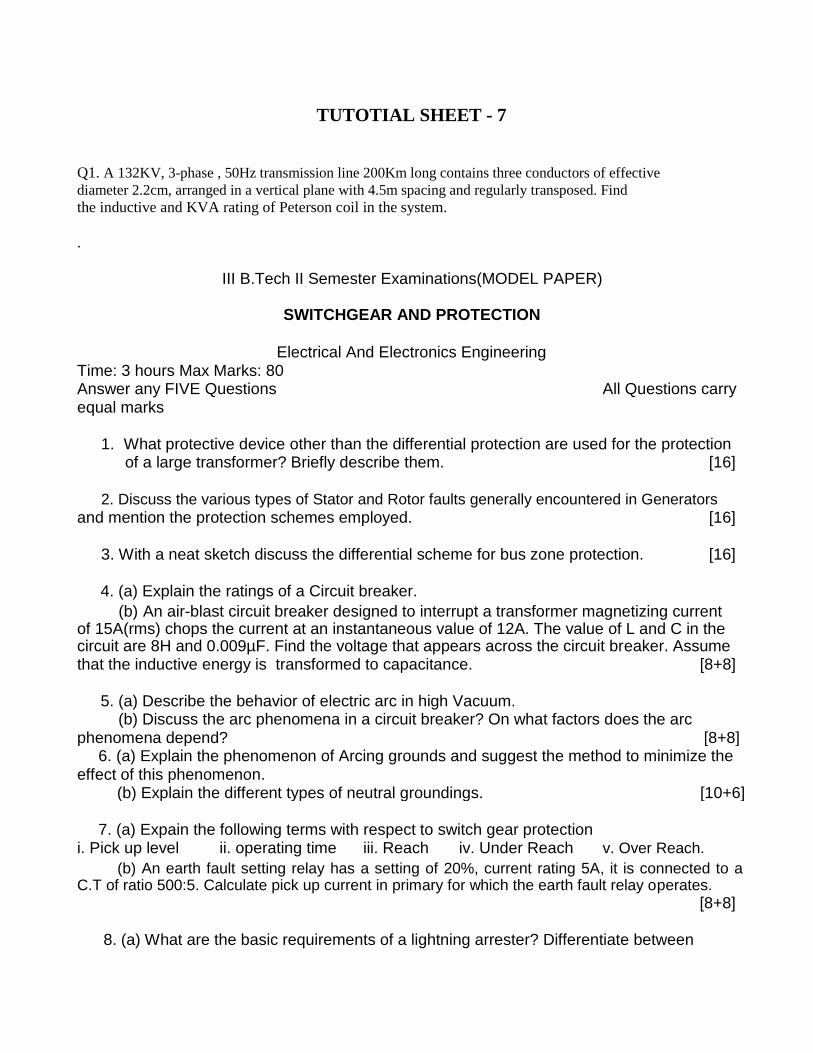
TUTOTIAL SHEET - 7
Q1. A 132KV, 3-phase , 50Hz transmission line 200Km long contains three conductors of effective diameter 2.2cm, arranged in a vertical plane with 4.5m spacing and regularly transposed. Find
the inductive and KVA rating of Peterson coil in the system.
.
III B.Tech II Semester Examinations(MODEL PAPER)
SWITCHGEAR AND PROTECTION
Electrical And Electronics Engineering Time: 3 hours Max Marks: 80 Answer any FIVE Questions All Questions carry equal marks
1. What protective device other than the differential protection are used for the protection of a large transformer? Briefly describe them. [16]
2. Discuss the various types of Stator and Rotor faults generally encountered in Generators and mention the protection schemes employed. [16]
3. With a neat sketch discuss the differential scheme for bus zone protection. [16]
4. (a) Explain the ratings of a Circuit breaker. (b) An air-blast circuit breaker designed to interrupt a transformer magnetizing current
of 15A(rms) chops the current at an instantaneous value of 12A. The value of L and C in the circuit are 8H and 0.009µF. Find the voltage that appears across the circuit breaker. Assume that the inductive energy is transformed to capacitance. [8+8]
5. (a) Describe the behavior of electric arc in high Vacuum. (b) Discuss the arc phenomena in a circuit breaker? On what factors does the arc
phenomena depend? [8+8] 6. (a) Explain the phenomenon of Arcing grounds and suggest the method to minimize the
effect of this phenomenon.
(b) Explain the different types of neutral groundings. [10+6]
7. (a) Expain the following terms with respect to switch gear protection i. Pick up level ii. operating time iii. Reach iv. Under Reach v. Over Reach.
(b) An earth fault setting relay has a setting of 20%, current rating 5A, it is connected to a C.T of ratio 500:5. Calculate pick up current in primary for which the earth fault relay operates.
[8+8]
8. (a) What are the basic requirements of a lightning arrester? Differentiate between
i. A lightning arrester and a lightning conductor ii. Surge diverter and surge absorber.
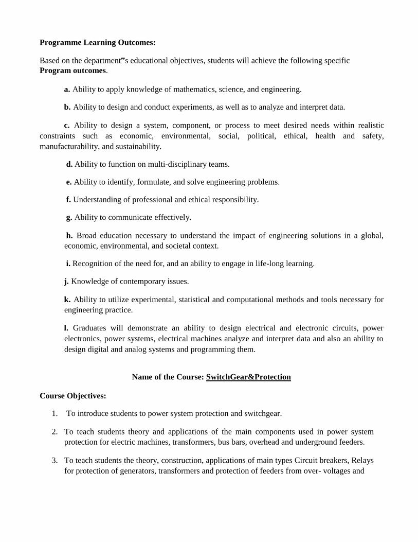
Programme Learning Outcomes:
Based on the department‟s educational objectives, students will achieve the following specific
Program outcomes.
a. Ability to apply knowledge of mathematics, science, and engineering.
b. Ability to design and conduct experiments, as well as to analyze and interpret data.
c. Ability to design a system, component, or process to meet desired needs within realistic
constraints such as economic, environmental, social, political, ethical, health and safety,
manufacturability, and sustainability.
d. Ability to function on multi-disciplinary teams.
e. Ability to identify, formulate, and solve engineering problems.
f. Understanding of professional and ethical responsibility.
g. Ability to communicate effectively.
h. Broad education necessary to understand the impact of engineering solutions in a global,
economic, environmental, and societal context.
i. Recognition of the need for, and an ability to engage in life-long learning.
j. Knowledge of contemporary issues.
k. Ability to utilize experimental, statistical and computational methods and tools necessary for
engineering practice.
l. Graduates will demonstrate an ability to design electrical and electronic circuits, power
electronics, power systems, electrical machines analyze and interpret data and also an ability to
design digital and analog systems and programming them.
Name of the Course: SwitchGear&Protection
Course Objectives:
1. To introduce students to power system protection and switchgear.
2. To teach students theory and applications of the main components used in power system
protection for electric machines, transformers, bus bars, overhead and underground feeders.
3. To teach students the theory, construction, applications of main types Circuit breakers, Relays
for protection of generators, transformers and protection of feeders from over- voltages and

other hazards. It emphasis on neutral grounding for overall protection
4. To develop an ability and skill to design the feasible protection systems needed for each main
part of a power system in students.
Course Outcomes: 1.Student g a i n s knowledge on different Protective Equipments or Power Systems
2. Know about various protective systems- how it works and where it works?
3. Different applications o f the relays, circuit breakers, gr ou n d i n g for different elements of power system is also discussed in the subject.
4. Ability to discuss Recovery and Restriking. 5. Ability to express Oil circuit Breaker, Air Blast circuit Breakers, SF6 Circuit Breaker.
6.Abiity to identify DMT,IDMT type relays 7. Ability to identify Rotor, Stator Faults, interturn faults and their protection.
Assessment methods:
1. Regular attendance to classes. 2. Seminars. 3. Written tests clearly linked to learning objectives
Classroom assessment techniques like tutorial sheets and assignments.
1. Program Educational Objectives (PEOs) – Vision/Mission Matrix
Vision/Mission Vision of the Institute Mission of the Institute Mission of the Program
PEOs
1 X X
2 X X X
3 X X X
4 X X
2. Program Educational Objectives(PEOs)-Program Outcomes(POs) Relationship Matrix
P-Outcomes a b c d e f g h i j K l
PEOs
1 X X X X X X X X X X
2 X X X X X X X X X X
3 X X X X X X X X
4 X X X X

3. Course Objectives-Course Outcomes Relationship Matrix
Course-Outcomes 1 2 3 4 5 6 7
Course-Objectives
1 X X
2 X X X X X
3 X X X
4 X X X X
4. Course Objectives-Program Outcomes (POs) Relationship Matrix P-Outcomes a b c d e f g h I j k l
C-Objectives
1 X X
2 X X X X X X
3 X X X X X X X X
4 X X X X X X X X
5. Course Outcomes-Program Outcomes (POs) Relationship Matrix
P-Outcomes a b c d e f g h i j k l
C-Outcomes
1 X X
2 X X X X
3 X X X X X X X X X X
4 X X X X X X X
5 X X X
6 X X
7 X X X X X
6. Courses (with title & code)-Program Outcomes (POs) Relationship Matrix
P-Outcomes a b c d e f g h i j k l
Courses
Electrical X X X X X X X X X X X
Machines-I
7. Program Educational Objectives (PEOs)-Course Outcomes Relationship Matrix
P-Objectives (PEOs) 1 2 3 4
Course-Outcomes
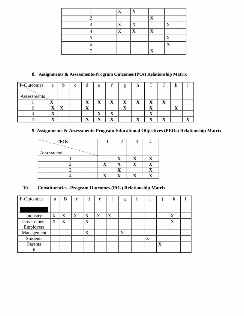
1 X X
2 X
3 X X X
4 X X X
5 X
6 X
7 X
8. Assignments & Assessments-Program Outcomes (POs) Relationship Matrix
P-Outcomes a b c d e f g h I J k l
Assessments
1 X X X X X X X X
2 X X X X X X
3 X X X X
4 X X X X X X X X
9. Assignments & Assessments-Program Educational Objectives (PEOs) Relationship Matrix
PEOs 1 2 3 4
Assessments 1 X X X
2 X X X X
3 X X
4 X X X X
10. Constituencies -Program Outcomes (POs) Relationship Matrix
P-Outcomes a B c d e f g h i j k l
Constituencies
Industry X X X X X X X
Government X X X X
Employers
Management X X
Students X
Parents X
6

SCHEDULE OF INSTRUCTIONS
COURSE PLAN
Course Objectives:
1. To introduce students to power system protection and switchgear. 2. To teach students theory and applications of the main components used in power system
protection for electric machines, transformers, bus bars, overhead and underground feeders. 3. To teach students the theory, construction, applications of main types Circuit breakers,
Relays for protection of generators, transformers and protection of feeders from over-
voltages and other hazards. It emphasis on neutral grounding for overall protection.
4. To develop an ability and skill to design the feasible protection systems needed for each
main part of a power system in students.
Course Outcomes:
At the end of the course student will have ability to
1.Student g a i n s knowledge on different Protective Equipments or Power Systems 2. Know about various protective systems- how it works and where it works? 3. Different applications o f the relays, circuit breakers, gr ou n d i n g for different elements of power system is also discussed in the subject. 4. Ability to discuss recovery and Restriking. 5. Ability to express Oil circuit Breaker, Air Blast circuit Breakers, SF6 Circuit Breaker. 6.Abiity to identify DMT,IDMT type relays 7. Ability to identify Rotor, Stator Faults, inter turn faults and their protection.
TUTOTIAL SHEET
Q1. A 50 Hz, 11 kV, three phase alternator with earthed neutral has a reactance of 5 ohm/phase and is connected to the bus-bar through a circuit breaker. The capacitance to earth between the alternator and the circuit breaker is 0.02 microfarad per phase. Assume the resistance of the generator to be negligible. Calculate the following. (a) Maximum value of voltage across the contacts of the circuit breaker
(b) Frequency of oscillation (c) The average rate of rise of restriking voltage up to first peak Q2. (a) A 11KV, 100MVA alternator is grounded through a resistance of 5. The C.T.s have a ratio 1000/5. The relay is set to operate when there is an out of balance current of 1A. What percentage of the generator winding will be protected by the percentage differential scheme of protection? (b) A 11KV,100MVA alternator is provided with differential protection. The percentage of winding to be
protected against phase to ground fault is 85%. The relay is set to operate when there is 20% of out of
balance current. Determine the value of the resistance to be placed in the neutral to ground
connection.

Q3. An 11kV,100MVA generator is provided with differential scheme of protection. The percentage of the generator winding to be protected against phase to ground fault is 80%. The relay is said to operate when there is 15% out of balance current. Determine the value of resistance to be placed in the neutral to ground connection. Q4. A circuit interrupts the magnetizing current of a 100MVA transformer at 220kV. The magnetizing
current is 5% of the full load current. Determine the maximum voltage which may appear across the Gap of the breaker when the magnetizing current is interrupted at 53% of its peak value. The stray capacitance is 2500 microfarad. The inductance is 30H.
Q5. A 3-phase transformer rated for 33kV/6.6kV is connected star-delta and the protecting current transformer on the low voltage side have a ratio of 400/5. Determine the ratio of the current transformer on the HV side. Q6. A 3-phase, 66/11kV star-delta connected transformer is protected by Merz- price protection system. The CTs on the LT side have a ratio of 420/5 ampr. Show that the CTs on the HT side will have a ratio of 70: 5"3 . Q6. A 3-phase, 33/6.6 kV transformer is connected in star/delta and the protecting current transformer on the LV side have a ratio of 300/5. What will be the ratio of the current transformer on the HV side?
Q7. A132KV, 3-phase 50Hz overhead distribution line has phase to ground shunt capacitance of 0.0157μF
per km. determine the inductance and KVA rating of arc suppression coil to be connected between
neutral and earth. Q8. A 50Hz, 3 phase overhead line has phase ground shunt capacitance of 0.08μF. determine
the inductance required in neutral to ground circuit to eliminate an arcing-ground at (a) other end of
the line (b) at 70% length of line from the neutral earthing end.
Q9. A 132KV, 3-phase , 50Hz transmission line 200Km long contains three conductors of effective diameter 2.2cm, arranged in a vertical plane with 4.5m spacing and regularly transposed. Find
the inductive and KVA rating of Peterson coil in the system.
Iv B.Tech II Semester Examinations(MODEL PAPER)
SWITCHGEAR AND PROTECTION
Electrical And Electronics Engineering Time: 3 hours Max Marks: 80 Answer any FIVE Questions All Questions carry equal marks
1. What protective device other than the differential protection are used for the protection of a large transformer? Briefly describe them. [16]
2. Discuss the various types of Stator and Rotor faults generally encountered in Generators and mention the protection schemes employed. [16]
3. With a neat sketch discuss the differential scheme for bus zone protection. [16]
4. (a) Explain the ratings of a Circuit breaker. (b) An air-blast circuit breaker designed to interrupt a transformer magnetizing current
of 15A(rms) chops the current at an instantaneous value of 12A. The value of L and C in the circuit are 8H and 0.009µF. Find the voltage that appears across the circuit breaker. Assume that the inductive energy is transformed to capacitance. [8+8]

5. (a) Describe the behavior of electric arc in high Vacuum. (b) Discuss the arc phenomena in a circuit breaker? On what factors does the arc
phenomena depend? [8+8] 6. (a) Explain the phenomenon of Arcing grounds and suggest the method to minimize the
effect of this phenomenon.
(b) Explain the different types of neutral groundings. [10+6]
7. (a) Expain the following terms with respect to switch gear protection i. Pick up level ii. operating time iii. Reach iv. Under Reach v. Over Reach.
(b) An earth fault setting relay has a setting of 20%, current rating 5A, it is connected to a C.T of ratio 500:5. Calculate pick up current in primary for which the earth fault relay operates.
[8+8] 8. (a) What are the basic requirements of a lightning arrester? Differentiate between
i. A lightning arrester and a lightning conductor ii. Surge diverter and surge absorber.
