st. martin’s engineering collegesmec.ac.in/sites/default/files/lab1/surveying lab- i.pdf · st....
TRANSCRIPT

1
(Approved by AICTE, Affiliated to JNTU, Hyderabad)
Department of Civil Engineering
SURVEYING LAB – I MANUAL
ST. MARTIN’S ENGINEERING COLLEGE DHULAPALLY, SECUNDERABAD

2
Experiment No: 1
Survey of an Area by Chain Survey (Closed Traverse) & Plotting
1.1 OBJECTIVE: To survey an open field by chain survey in order to calculate the area of the field.
1.2 RESOURCES:
S. No. Name of the Equipment Range Type Quantity
1 Chain Metric chain 20m or 30m 1
2 Tape Linen Tape 20m 1
3 Ranging Rods 3m or 2m height 5
4 Arrows 5
5 Cross Staff 1
1.3 PRECAUTIONS: 1. Chainages must be marked against the working edge of the offset scale. 2. The plan must be so oriented on the sheet that the north side of the survey lies towards the top of the sheet. 3. Each triangle must be verified by measuring the check lines. 1.4 FIGURE:
Survey of an Open Field (Closed Traverse)
1.5 PROCEDURE: Ranging a line: It is the process of establishing a number of intermediate points on a survey line joining two stations in the field, so that all the points on the line are in alignment and the length between stations may be measured accurately.

3
Two ranging rods are erected vertically at the end stations by two surveyors who are standing behind ranging rods. One of the surveyors from one of the end stations directs the assistant to hold the ranging rod vertically to establish an intermediate point and move the rod either to the left or right until the ranging rod is in alignment with the end stations. Finally, when the ranging is correct, the assistant is directed to fix the ranging rod at that point. All the directions from surveyor should be as per the Code of Signals given in Table 1. Taking offsets: The perpendicular distance measured right or left of the chain line to locate the details like corners, boundaries, culverts, etc is known as offset. Offsets can be taken by two ways: 1. By Tape and 2. By Cross-Staff. By Tape: The leader holds the zero end of the tape at the point where the offset is to be taken and the follower swings off the tape in an arc across the chain line to left and right. The minimum reading of tape on the chain line gives the position of the foot of the perpendicular from the required point. By Cross-Staff: The Cross-Staff is held vertically on the chain line approximately near the point where the offset is likely to fall. The Cross-Staff is turned until the signal at one end of the chain line is viewed through one pair of slits. The surveyor then takes a round and views through the other pair of silts. If the point to which the offset is to be taken is seen, the point below the instrument is the required foot of the offset. On the other hand, if the point is not seen, the surveyor moves along the chain line, without twisting the Cross-Staff, till the point appears. Procedure for surveying the given open field (Closed Traverse): ABCDEF is the required closed traverse open field to be surveyed for calculating the area as shown in Fig 1. From the station A the length of all the opposite corners such as AC, AD and AE are measured with a chain and the longest distance is considered for laying off the main chain line. In this case AD is the longest and a chain line running from A to D is laid. Offsets to corner points B, C, E and F are now laid from the chain line AD either by tape or cross-staff and their foot of offsets are G, I, J, H respectively. All the offset lengths GB, HF, IC and JE are measured either by chain or tape depending on the length of offsets. The distances between all the points AG, GH, HI, IJ and JD are also measured along the chain line.
4
1.6 AREA CALCULATIONS:
Area No. Base (m) Height (m) Area (m2)
1.7RESULT: The total Area of the given Open Field by Chain Survey = sqm 1.8 PRELAB QUESTIONS: 1. How the chains are classified? 2. How many types of cross staves are there? 3. What is ranging? 4. What is closed traverse? 1.9 LAB ASSIGNMNET: You are required to plot the closed traverse in the lab record on the left side of page with all measurements to a scale. 1.10 POSTLAB QUESTIONS: 1. How the offsets are taken in the field? 2. What are the precautions are to be taken in erecting perpendiculars? 3. What is indirect ranging and how it can be done? 4. What is base line and check line?

5
Experiment No: 2
Chaining Across Obstacles
1.1 OBJECTIVE: To survey an area by chain survey across obstacles and to calculate the obstructed lengths by using different methods. 1.2 RESOURCES: S. No. Name of the Equipment Range Type Quantity
1 Chain Metric chain 20m or 30m 1
2 Tape Linen Tape 20m 1
3 Ranging Rods 3m or 2m height 5
4 Arrows 5
5 Cross Staff 1
1.3 PRECAUTIONS: 1. Chainages must be marked against the working edge of the offset scale. 2. The plan must be so oriented on the sheet that the north side of the survey lies towards the top of the sheet. 3. Perpendiculars must be erected carefully with full accuracy . 1.4 FIGURE:
6
1.5 PROCEDURE:
Obstacles to Chaining: During measurements, it is impossible to set out all the chain lines in a straightforward method because of a variety of obstacles to chaining and ranging in the field. Obstacles to measurement: The obstacles which do not obstruct the ranging (view) like ponds, rivers are known as Obstacles to Measurement. Obstacles to alignment: The obstacles which we cannot see across, i.e. both the chaining and ranging are obstructed, e.g. houses, stacks, etc. are known as Obstacles to Alignment. Obstacles to measurement: First Method: Let ABCD be a chain line obstructed by a pond (Fig 1). Let BC be the obstructed length. Two offsets BE and CF of equal lengths are made at B and C and chaining is done along EF to measure the distance EF. Now the required obstructed length BC is equal to the measured distance EF. Therefore, BC = EF Second Method: Let AB be the obstructed length across the river (Fig 2). AC is laid off, of any convenient length, perpendicular to the required distance AB.

7
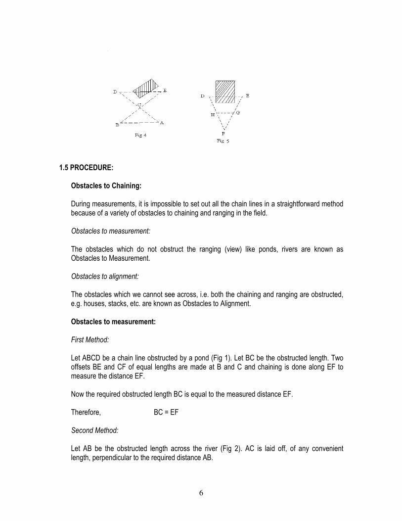
Now a perpendicular is laid off from C such that it meets the extended line of AB at D. Triangles ABC and ADC are similar triangles. From the principle of similar triangles, AB / AC = AC / AD Therefore, obstructed length AB = AC2 / AD Third Method: Let AB be a chain line obstructed by a river (Fig 3). A point I is assumed anywhere in line with the required distance AB. A point H is taken in such a way that HJ = HI and HK = HB. Now a point L is established in line AH and at the same time in the line JK produced. Triangles KHL and ABH are similar triangles and their corresponding sides are equal to each other as the points K, B and I, J are equidistant either side from H. Therefore, the obstructed length AB = KL Obstacles to alignment: First Method: Let DE be the obstructed length across the building (Fig 4). A point C is assumed arbitrarily. E and C are joined such that EC = CB. Now D and C are also joined such that DC = CA. Triangles CDE and CBA are similar triangles and their corresponding sides are equal to each other as points BE and AD are equidistant either side from C. Therefore, obstructed length DE = BA
Second Method: Let DE be the obstructed length across the building (Fig 5). A point F is established at equal distances from D and E at any convenient distance. Points H and G are established such that FH = FG. Triangles FDE and FHG are similar triangles. From the principle of similar triangles, DE / DF = HG / HF Therefore, obstructed length DE = (HG X DF) / HF

8
1.6 CALCULATIONS: 1.7RESULT:
Obstacles to measurement: Obstructed length from First Method = m Obstructed length from Second Method = m Obstructed length from Third Method = m Obstacles to alignment: Obstructed length from First Method = m Obstructed length from Second Method = m
1.8 PRELAB QUESTIONS: 1. What is obstacle to chaining? 2. What is obstacle to ranging? 3. What is the least count of metric chain? 4. What is indirect ranging and how it can be done? 1.9 LAB ASSIGNMNET: You are required to conduct the experiment by adopting above procedure for a given obstacle. 1.10 POSTLAB QUESTIONS: 1. How the offsets are taken in the field with out cross staff? 2. What are the precautions are to be taken in indirect ranging? 3. What is obstacle to chaining and ranging both? 4. What is line ranger?

9
Experiment No: 3
Determination of Distance between two Inaccessible Points with Compass
1.1 OBJECTIVE: To determine distance between two inaccessible points using Prismatic Compass. 1.2 RESOURCES: S. No. Name of the Equipment Range Type Quantity
1 Chain Metric chain 20m or 30m 1
2 Tape Linen Tape 20m 1
3 Ranging Rods 3m or 2m height 3
4 Arrows 5
5 Compass Prismatic Compass 1
6 Tripod Compass Tripod 1
1.3 PRECAUTIONS: 1. Temporary adjustments must be done carefully. 2. The plan must be so oriented on the sheet that the north side of the survey lies towards the top of the sheet. 3. Ground points must be transferred to paper with full accuracy. 1.4 FIGURE:

10
1.5 PROCEDURE: Temporary Adjustments of Compass: Centering: A tripod is placed over the station with its legs spread well apart so that it is at a workable height. The compass is fixed on the tripod. It is then centered over the station where the reading is to be taken. A plumb bob is hung from the centre of compass. In case the arrangement for a plumb bob is not provided, a stone is dropped from below the compass and it should fall on the peg marking the ground station. Levelling: The compass is levelled by eye judgment. This is essential so that the graduated ring swings freely. Focusing the Prism: The prism is moved up or down till the figures and graduations are seen clearly. Inaccessible Distance: When two points are too far away, unreachable and the chaining between them is difficult, the distance between these two points is called Inaccessible Distance. But the two points are visible to each other.
11
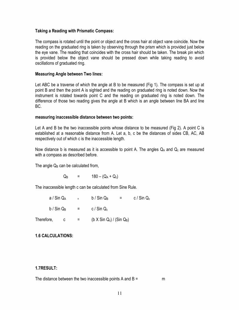
Taking a Reading with Prismatic Compass: The compass is rotated until the point or object and the cross hair at object vane coincide. Now the reading on the graduated ring is taken by observing through the prism which is provided just below the eye vane. The reading that coincides with the cross hair should be taken. The break pin which is provided below the object vane should be pressed down while taking reading to avoid oscillations of graduated ring. Measuring Angle between Two lines: Let ABC be a traverse of which the angle at B to be measured (Fig 1). The compass is set up at point B and then the point A is sighted and the reading on graduated ring is noted down. Now the instrument is rotated towards point C and the reading on graduated ring is noted down. The difference of those two reading gives the angle at B which is an angle between line BA and line BC. measuring inaccessible distance between two points: Let A and B be the two inaccessible points whose distance to be measured (Fig 2). A point C is established at a reasonable distance from A. Let a, b, c be the distances of sides CB, AC, AB respectively out of which c is the inaccessible length. Now distance b is measured as it is accessible to point A. The angles QA and Qc are measured with a compass as described before. The angle QB can be calculated from, QB = 180 – (QA + Qc) The inaccessible length c can be calculated from Sine Rule. a / Sin QA = b / Sin QB = c / Sin Qc
b / Sin QB = c / Sin Qc
Therefore, c = (b X Sin Qc) / (Sin QB) 1.6 CALCULATIONS: 1.7RESULT: The distance between the two inaccessible points A and B = m

12
1.8 PRELAB QUESTIONS: 1. What are the differences between prismatic and surveyors compass? 2. What is Azimuth? 3. What is the least count of prismatic compass? 4. What is WCB and RB? 1.9 LAB ASSIGNMNET: You are required to calculate the distance between two inaccessible points by adopting above procedure. 1.10 POSTLAB QUESTIONS: 1. How the readings on a prismatic compass are marked? 2. What are the precautions are to be taken while conducting experiment? 3. What are inaccessible points?
13
Experiment No: 4
Surveying of a given area by prismatic compass (Closed Traverse) and plotting after adjustment
1.1 OBJECTIVE: To survey an area (Closed Traverse) by Compass Survey and to plot the area after adjustment. 1.2 RESOURCES: S. No. Name of the Equipment Range Type Quantity
1 Tape Linen Tape 20m 1
2 Ranging Rods 3m or 2m height 3
3 Arrows 5
4 Compass Prismatic Compass 1
5 Tripod Compass Tripod 1
1.3 PRECAUTIONS: 1. The plan must be so oriented on the sheet that the north side of the survey lies towards the top of the sheet 2. Temporary adjustments must be done carefully. 3. Compass readings must be taken with full accuracy 4. Care must be taken while centering the compass. 1.4 FIGURE:

14
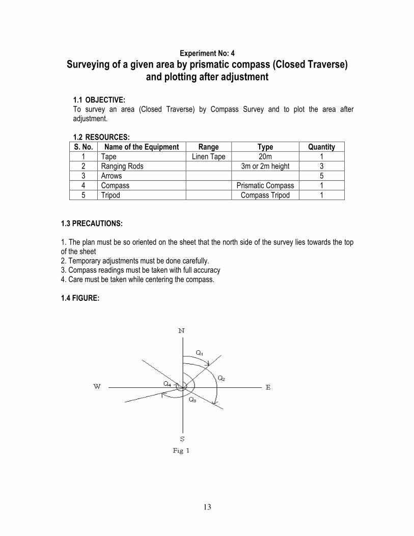
1.5 PROCEDURE: Whole Circle Bearing (WCB): The bearing of line that is always measured clockwise from the north point of the reference meridian towards the line right round the circle is known as Whole Circle Bearing (WCB). WCB will have values between 00 and 3600. Q1, Q2, Q3, etc in Fig 1 represent WCBs. Fore or Forward Bearing (FB) (WCB System): The bearing of line in the direction of progress of the survey is called Fore or Forward Bearing. Back or Reverse Bearing (BB) (WCB System): The bearing of a line in the opposite direction of progress of the survey is known as Back or Reverse Bearing. The bearing of a line is indicated in the order in which the line is lettered. Thus, the bearing from A to B (Fig 2) is the fore bearing Q of the line AB, whereas the bearing of line AB in the direction B to A is its back bearing P.
15
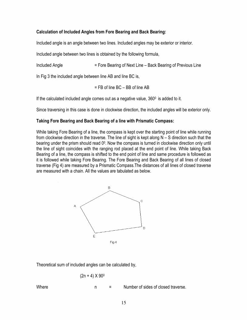
Calculation of Included Angles from Fore Bearing and Back Bearing: Included angle is an angle between two lines. Included angles may be exterior or interior. Included angle between two lines is obtained by the following formula, Included Angle = Fore Bearing of Next Line – Back Bearing of Previous Line In Fig 3 the included angle between line AB and line BC is, = FB of line BC – BB of line AB If the calculated included angle comes out as a negative value, 3600 is added to it. Since traversing in this case is done in clockwise direction, the included angles will be exterior only. Taking Fore Bearing and Back Bearing of a line with Prismatic Compass: While taking Fore Bearing of a line, the compass is kept over the starting point of line while running from clockwise direction in the traverse. The line of sight is kept along N – S direction such that the bearing under the prism should read 00. Now the compass is turned in clockwise direction only until the line of sight coincides with the ranging rod placed at the end point of line. While taking Back Bearing of a line, the compass is shifted to the end point of line and same procedure is followed as it is followed while taking Fore Bearing. The Fore Bearing and Back Bearing of all lines of closed traverse (Fig 4) are measured by a Prismatic Compass.The distances of all lines of closed traverse are measured with a chain. All the values are tabulated as below.
Theoretical sum of included angles can be calculated by, (2n + 4) X 900 Where n = Number of sides of closed traverse.
16
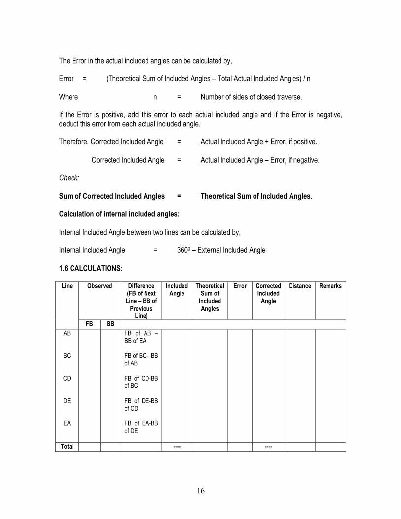
The Error in the actual included angles can be calculated by, Error = (Theoretical Sum of Included Angles – Total Actual Included Angles) / n Where n = Number of sides of closed traverse. If the Error is positive, add this error to each actual included angle and if the Error is negative, deduct this error from each actual included angle. Therefore, Corrected Included Angle = Actual Included Angle + Error, if positive. Corrected Included Angle = Actual Included Angle – Error, if negative. Check: Sum of Corrected Included Angles = Theoretical Sum of Included Angles. Calculation of internal included angles: Internal Included Angle between two lines can be calculated by, Internal Included Angle = 3600 – External Included Angle 1.6 CALCULATIONS: Line Observed Difference
(FB of Next Line – BB of Previous Line)
Included Angle
Theoretical Sum of Included Angles
Error Corrected Included Angle
Distance Remarks
FB BB AB
BC
CD
DE
EA
FB of AB – BB of EA FB of BC– BB of AB FB of CD-BB of BC FB of DE-BB of CD FB of EA-BB of DE
Total ---- ----
17
1.7RESULT: Distances: AB = m BC = m CD = m DE = m EA = m Included Angles: Angle A = Angle B = Angle C = Angle D = Angle E = 1.8 PRELAB QUESTIONS: 1. What is Fore Bearing and Back Bearing? 2. What is magnetic Declination? 3. What is local attraction? 4. What is WCB and RB? 5. What is an included angle? 1.9 LAB ASSIGNMNET: You are required to Survey a given area by prismatic compass (Closed Traverse) by adopting above procedure. 1.10 POSTLAB QUESTIONS: 1. How the check is to be performed? 2. What are the differences between prismatic and surveyors compass? 3. How to eliminate local attraction? 4. What is magnetic dip? 5. What is break pin?
18
Experiment No: 5
Radiation method, intersection methods by Plane Table Survey
1.1 OBJECTIVE: To plot a given area by Radiation and Intersection methods of Plane Table Survey. 1.2 RESOURCES: S. No. Name of the Equipment Range Type Quantity
1 Tape Linen Tape 20m 1
2 Ranging Rods 3m or 2m height 3
3 Arrows 5
4 Plane Table with Tripod and its accessories
1
5 Two Drawing Sheets 1
6 Drawing Clips
7 Pencil, Eraser and Pins
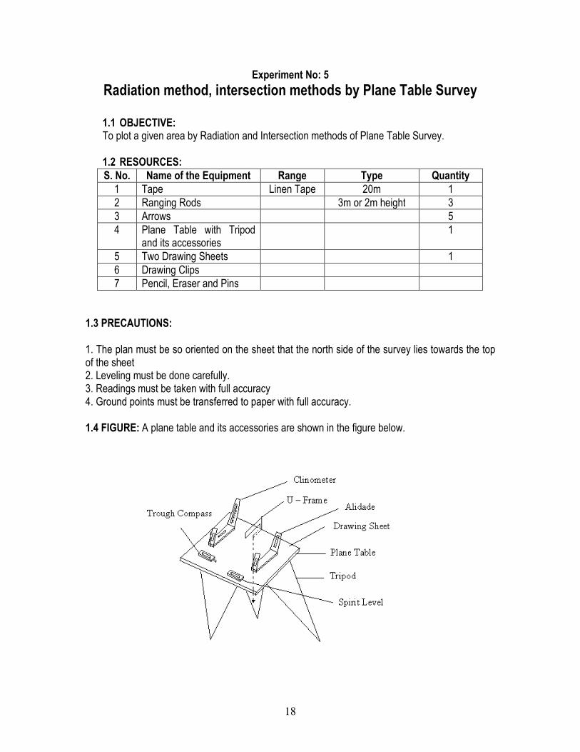
1.3 PRECAUTIONS: 1. The plan must be so oriented on the sheet that the north side of the survey lies towards the top of the sheet 2. Leveling must be done carefully. 3. Readings must be taken with full accuracy 4. Ground points must be transferred to paper with full accuracy. 1.4 FIGURE: A plane table and its accessories are shown in the figure below.
19
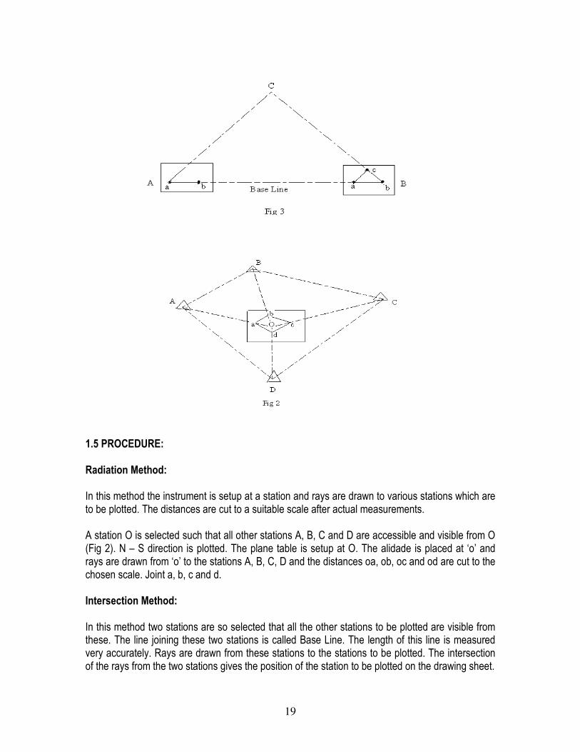
1.5 PROCEDURE: Radiation Method: In this method the instrument is setup at a station and rays are drawn to various stations which are to be plotted. The distances are cut to a suitable scale after actual measurements. A station O is selected such that all other stations A, B, C and D are accessible and visible from O (Fig 2). N – S direction is plotted. The plane table is setup at O. The alidade is placed at ‘o’ and rays are drawn from ‘o’ to the stations A, B, C, D and the distances oa, ob, oc and od are cut to the chosen scale. Joint a, b, c and d.
Intersection Method: In this method two stations are so selected that all the other stations to be plotted are visible from these. The line joining these two stations is called Base Line. The length of this line is measured very accurately. Rays are drawn from these stations to the stations to be plotted. The intersection of the rays from the two stations gives the position of the station to be plotted on the drawing sheet.

20
Let A and B be the two accessible stations (Fig 3), such that A and B can be suitably plotted. C is the station to be plotted by intersection. The plane table is placed at A. N – S direction is plotted. The ground station A is transferred as ‘a’ onto the drawing sheet. With the alidade centered at ‘a’, station B is sighted. A ray aB is drawn and is cut as ‘ab’ to a suitable scale. With the alidade at ‘a’, C is also sighted and a ray aC is drawn. The table is now shifted to B and is setup. The alidade is placed at ‘b’ and C is sighted. A ray bC is drawn. The intersection of the two rays gives the position of C as ‘c’ on the plane table. 1.6 CALCULATIONS: 1.7RESULT: Given area is plotted on paper by Radiation and Intersection methods of Plane Table Survey. 1.8 PRELAB QUESTIONS: 1. What is the advantage of plane table survey? 2. What is Alidade? 3. What is plane table orientation? 4. What are the limitations of plane table survey? 1.9 LAB ASSIGNMNET: You are required to plot a given area by Radiation and Intersection methods of Plane Table Survey by adopting above procedure. 1.10 POSTLAB QUESTIONS: 1. How the Radiation method is different from Intersection method? 2. When Intersection method is suitable? 3. What are inaccessible points? 4. What is orientation by back sighting?

21
Experiment No: 6
Two point and three point problems in plane table survey
1.1 OBJECTIVE: To find the required stations by using two point problem and Three point problem.
1.2 RESOURCES:
S. No. Name of the Equipment Range Type Quantity
1 Tape Linen Tape 20m 1
2 Ranging Rods 3m or 2m height 3
3 Arrows 5
4 Plane Table with Tripod and its accessories
1
5 Two Drawing Sheets 1
6 Drawing Clips
7 Pencil, Eraser and Pins
1.3 PRECAUTIONS: 1. The plan must be so oriented on the sheet that the north side of the survey lies towards the top of the sheet 2. Leveling must be done carefully. 3. Readings must be taken with full accuracy 4. Ground points must be transferred to paper with full accuracy. 1.4 FIGURE: A plane table and its accessories are shown in the figure below.

22
1.5 PROCEDURE FOR TWO POINT PROBLEM:
A. Let two points A and B be the plotted positions on the plane. B. C is the station over which the table is to be set up and c is its position on the plane which is required to be located. C. The solution of the problem requires two instrument stations. D. The station is obtained as follows. 1) Choose a suitable auxiliary point D, so that the angle CAD and CBD aren’t too acute for good intersection at A and B. 2) Setup the table at D and level it .Orient the table by compass or by judging ab to be parallel to AB and clamp it. 3) With the alidade touching a, sight A, and draw a ray through a. Similarly, with the alidade against b, sight B and draw a ray through through at d1,which approximately represents the station D and the orientation is approximately. 4) With the alidade centered on d1 ,sight C and draw a ray d1c1 through d1,estimating the position of c1. 5) Remove the table and set it up at C with c1over c and level it.Orient the table parallel to its position at D ,by back sighting on D .To do this ,place the alidade along c and d ,rotate the table until D is bisected, clamp the table . 6) With the alidade against a, sight A and draw a ray through a, Intersect the line c1d1in C1 .With the alidade through C1, sight B and draw a ray through C1..This ray will pass through b, provide the initial orientation of the table at D was correct. But since the orientation at D and also at C, also constituent was only approximate, the ray C 1 B will not pass through b. Mark the point of intersection b1 of C 1 B ,and d1b .The point b1 thus represents B. Hence points ad1c1b1 represents ADCB. But since ab is the true representation of AB ,the error in the initial orientation is equal to the angle b1ab between the lines ab and ab1.To eliminate the error ,the table must be rotate through this angle. To do this, 7) Place the alidade along ab1, and fix a ranging rod P at a great distance from the table in the line ab1 produced. 8) Place the alidade along ab and turn the table until the ranging rod P is bisected. Clamp the table ,ab is now parallel to AB and the orientation of the table is correct. 9) To find the true position of C, center the alidade on a and sight A .Draw a ray through a. Similarly with alidade touching b, sight B, and draw a ray through b. The intersection of these two rays gives the true position (c) on the plan of the station (c) occupied. 1.6 RESULT: The required instrument station C is occupied by using two point problem. 1.7 PROCEDURE FOR THREE POINT PROBLEM: 1) Plot a,b,c as in the ground.
2) The length of ab, bc and ac are given. It forms a triangle.
3) The alidade place along CA.
4) The board rotates till the point A is sighted and the board is clamped.

23
5) Pivot the alidade on a and sight to b and draw a ray .These two ray will meet at a point d. Then
joint bd, and rotate the board till the point B is sighted and draw a back ray.
6) This ray will meet at a point on the line bd, this will be the required station.
1.8 RESULT: The required instrument station C is occupied by using three point problem.

24
Experiment No: 7
Traversing by plane table survey
1.1 OBJECTIVE: Traversing method for running survey lines of a closed or open traverse.
1.2 RESOURCES:
S. No. Name of the Equipment Range Type Quantity
1 Tape Linen Tape 20m 1
2 Ranging Rods 3m or 2m height 3
3 Arrows 5
4 Plane Table with Tripod and its accessories
1
5 Two Drawing Sheets 1
6 Drawing Clips
7 Pencil, Eraser and Pins
1.3 PRECAUTIONS: 1. The plan must be so oriented on the sheet that the north side of the survey lies towards the top of the sheet 2. Leveling must be done carefully. 3. Readings must be taken with full accuracy 4. Ground points must be transferred to paper with full accuracy. 1.4 FIGURE: A plane table and its accessories are shown in the figure below.
A
E
D
B
C
25
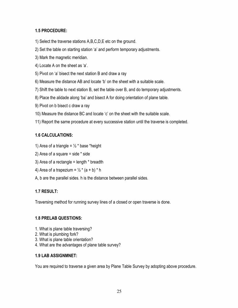
1.5 PROCEDURE: 1) Select the traverse stations A,B,C,D,E etc on the ground.
2) Set the table on starting station ‘a’ and perform temporary adjustments.
3) Mark the magnetic meridian.
4) Locate A on the sheet as ‘a’.
5) Pivot on ‘a’ bisect the next station B and draw a ray
6) Measure the distance AB and locate ‘b’ on the sheet with a suitable scale.
7) Shift the table to next station B, set the table over B, and do temporary adjustments.
8) Place the alidade along ‘ba’ and bisect A for doing orientation of plane table.
9) Pivot on b bisect c draw a ray
10) Measure the distance BC and locate ‘c’ on the sheet with the suitable scale.
11) Report the same procedure at every successive station until the traverse is completed.
1.6 CALCULATIONS: 1) Area of a triangle = ½ * base *height
2) Area of a square = side * side
3) Area of a rectangle = length * breadth
4) Area of a trapezium = ½ * (a + b) * h
A, b are the parallel sides. h is the distance between parallel sides.
1.7 RESULT: Traversing method for running survey lines of a closed or open traverse is done. 1.8 PRELAB QUESTIONS: 1. What is plane table traversing? 2. What is plumbing fork? 3. What is plane table orientation? 4. What are the advantages of plane table survey? 1.9 LAB ASSIGNMNET: You are required to traverse a given area by Plane Table Survey by adopting above procedure.

26
1.10 POSTLAB QUESTIONS: 1. What is the difference between open and closed traverse? 2. How the checks are applied on closed traverse accuracy? 3. Which material is used for making alidade? 4. What is the standard length of alidade?

27
Experiment No: 8 FLY LEVELLING (DIFFERENTIAL LEVELLING)
1.1 OBJECTIVE:
To ascertain the difference of elevation between any two points.
1.2 RESOURCES:
S. No. Name of the Equipment Range Type Quantity
1 Dumpy level 1
2 Ranging Rods 3m or 2m height 3
3 Arrows 5
4 leveling staff Folding staff 4m 1
5 Tripod Dumpy level Tripod 1
1.3 PRECAUTIONS: 1. Staff must be vertical while taking reading. 2. Leveling must be done carefully. 3. Readings must be taken with full accuracy 4. Temporary adjustments must be done carefully.. 1.4 FIGURE:
A dumpy level, builder's auto level, leveling instrument, or automatic level is an optical instrument used to establish or check points in the same horizontal plane. It is used in surveying and building with a vertical staff to measure height differences and so transfer, measure and set heights. A Dumpy level is shown in figure below.

28
1.5 PROCEDURE: 1. Differential leveling is the method of direct leveling the object of which is To determine
Difference in elevations of two points regardless of horizontal position of point with respect to each
Other, when points are apart it may be necessary to setup the instrument several times. This type
of Leveling is also known as “FLY-LEVELLING”.
2. Instrument level is setup at convenient positions near first point (say A).
3. Temporary adjustments should be done, (setting up, leveling up, elimination of a par-allot) are
Performed.
4. First sight of B.M (point of known elevation) is taken and reading is entered in back Sight
column.
5. If distance is large instrument is shifted, the instrument becomes turning point (or) changing
point.
6. After setting up instrument at new position, performing temporary adjustment and Take back
sight as turning point.
7. Thus turning point will have both back sight and fore sight readings.
8. Link wise the process is repeated till last point (say B) is reached.
9. Readings are entered in a tabular form is given Below and Reduced levels are calculate either
by height of instrument method (or) rise and fall method.
1.6 CALCULATIONS:
Simple leveling
St. No. BS IS FS HI RL Remarks
ARITHMETIC CHECK:- Σ B.S - ΣF.S=ΣRISE - ΣFALL=LAST RL - FIRST R.L

29
Differential leveling
St. No. BS IS FS HI RL Remarks
ARITHMETICAL CHECK:- ΣB.S – ΣF.S =Last R.L-First R.L
1.7 RESULT: Difference Between points = m. 1.8 PRELAB QUESTIONS: 1. What is Uses of Leveling? 2. What is Datum Surface or Line? 3. What is Reduced Level? 4. What is Line of Collimation? 1.9 LAB ASSIGNMNET: You are required to find the difference in levels for the given two points by adopting above procedure. 1.10 POSTLAB QUESTIONS: 1. What are the Instruments used in Leveling? 2. What is Simple Leveling? 3. What is Rise-and-Fall method? 4. What is the Need of Reciprocal Leveling?

30
Experiment No: 9 PROFILE LEVELLING (Longitudinal section & cross section, L.S & C.S)
1.1 OBJECTIVE:
Determining the elevation at various points on ground at regular interval.
1.2 RESOURCES:
S. No. Name of the Equipment Range Type Quantity
1 Dumpy level 1
2 Ranging Rods 3m or 2m height 3
3 Arrows 5
4 leveling staff Folding staff 4m 1
5 Tripod Dumpy level Tripod 1
1.3 PRECAUTIONS: 1. Staff must be vertical while taking reading. 2. Leveling must be done carefully. 3. Readings must be taken with full accuracy 4. Temporary adjustments must be done carefully.. 1.4 FIGURE:
A dumpy level, builder's auto level, leveling instrument, or automatic level is an optical instrument used to establish or check points in the same horizontal plane. It is used in surveying and building with a vertical staff to measure height differences and so transfer, measure and set heights. A Dumpy level is shown in figure below.

31
1.5 PROCEDURE: 1. Profile leveling is a method of surveying that has been carried out along the central line of a
track of land on which a linear engineering work is to be constructed/ laid. The operations involved
in determining the elevation of ground surface at small spatial interval along a line is called profile
leveling.
2. Divide the proposed center line of a given work at regular intervals.
3. Fix the level and do station adjustments.
4. Take Back Sight on Bench Mark.
5. Take Intermediate Sight on intermediate points.
6. Take Fore Sight on Change points and End point.
7. Record the values in field book in respective columns
32
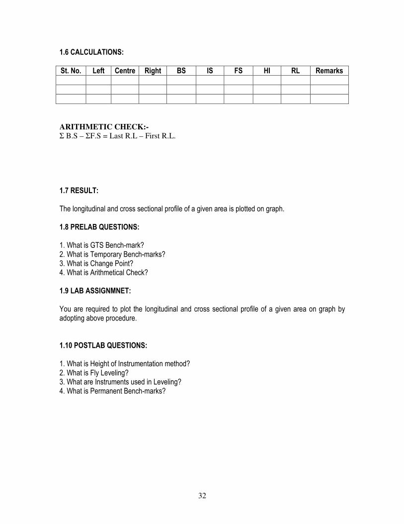
1.6 CALCULATIONS:
St. No. Left Centre Right BS IS FS HI RL Remarks
ARITHMETIC CHECK:-
Σ B.S – ΣF.S = Last R.L – First R.L. 1.7 RESULT: The longitudinal and cross sectional profile of a given area is plotted on graph. 1.8 PRELAB QUESTIONS: 1. What is GTS Bench-mark? 2. What is Temporary Bench-marks? 3. What is Change Point? 4. What is Arithmetical Check? 1.9 LAB ASSIGNMNET: You are required to plot the longitudinal and cross sectional profile of a given area on graph by adopting above procedure. 1.10 POSTLAB QUESTIONS: 1. What is Height of Instrumentation method? 2. What is Fly Leveling? 3. What are Instruments used in Leveling? 4. What is Permanent Bench-marks?

33
Experiment No: 10
Two exercises on Contouring
1.1 OBJECTIVE: Counter plan of given area (One full size drawing sheet).
1.2 RESOURCES:
S. No. Name of the Equipment Range Type Quantity
1 Dumpy level 1
2 Ranging Rods 3m or 2m height 3
3 Arrows 5
4 leveling staff Folding staff 4m 1
5 Tripod Dumpy level Tripod 1
6 prismatic compass 1
7 chain 20m 1
8 Tape 20m 1
1.3 PRECAUTIONS: 1. Staff must be vertical while taking reading. 2. Leveling must be done carefully. 3. Readings must be taken with full accuracy 4. Temporary adjustments must be done carefully. 1.4 FIGURE:

34
1.5 PROCEDURE: Contouring theory:
The elevation and depression and the undulations of the surface of the ground are shown as map
by interaction of level surface with by means of contour line. A contour may be defined as the line
of intersection of a level surface with the surface of the ground.
Characteristics of Counter Lines:
The following are the Characteristics of the contours/ contour lines.
1) All points on the same contour line will have the same elevation.
2) Contour lines close together represent steep ground, while uniform slope is indicated when
they are uniformly spaced. A series of straight, parallel and equally spaced contours show
a plane or flat surface.
3) Contour lines of different elevation cannot merge or cross one another on the map, expect
in the case of an overhanging cliff. A vertical cliff is indicated when several contours
coincide.

35
4) A contour line must close upon itself either within or without the limits of the map.
5) Series of closed contour lines on the map either represent a hill or a depression according
as the higher or lower values are inside them as shown in figs.
6) A contour will not stop in the middle of the plan. It will either close or go out of the plan.
7) Ridge or water shad and valley lines are the lines joining the top most or the bottom most
points of hill and valley respectively, cross the contours at right angles. A ridge line is
shown when the higher values are inside the loop, while in the case of a valley line, the
lower values are inside the loop as shown in figure.
Procedure:
a) Cross-section method: This method is commonly used in rough survey, cross sections are run
traverse to the contour line of road, and railway as canal and the point of change of slope
(representations) are located. The cross-section line may be inclined at any angle to the centerline
if necessary. The spacing of the cross sections depends upon the characteristics of the ground. By
interpolation of contour is meant the process of spacing the contour proportioning between the
plotted ground points. Contour may be interpolated by
1) Estimation
2) Arithmetical calculations
3) Graphical method.
In all these methods it is assumed that the slope of the ground between any two random points is
uniform.
1.7 RESULT: The contour of given land is drawn in the sheet. 1.8 PRELAB QUESTIONS: 1. What is contouring? 2. What are the properties of contours? 3. What are the uses of contours? 4. What is Bench mark? 1.9 LAB ASSIGNMNET: You are required to construct contour plan of given land by adopting above procedure.

36
1.10 POSTLAB QUESTIONS: 1. What is Height of Instrumentation method? 2. What is cross section method? 3. What are indirect methods for plotting contours? 4. What are the uses of contours?

37
INDEX
List of Exercises:
1. Survey of an area by chain survey (closed traverse) & plotting.
2. Chaining across obstacles.
3. Determine of distance between two inaccessible points with compass.
4. Survey of a given area by prismatic compass (closed traverse) and plotting after adjustment.
5. Radiation method, intersection methods by plane table survey.
6. Two point and three point problems in plane table survey.
7. Traversing by plane table survey.
8. Fly leveling (differential leveling).
9. An exercise of L. S. and C. S. and plotting.
10. Two exercises on contouring.