stick/tig st80i plus welder - northern toolstick/tig st80i plus welder owner’s manual warning:...
TRANSCRIPT

SAVE THESE INSTRUCTIONS
Stick/TIG ST80i Plus Welder
Owner’s Manual
WARNING: Read carefully and understand all ASSEMBLY AND OPERATION
INSTRUCTIONS before operating. Failure to follow the safety rules and other basic safety
precautions may result in serious personal injury.
Item #55728
Page 2 of 25
Thank you very much for choosing a Klutch®
product!
For future reference, please complete the owner’s record below:
Serial Number/Lot Date Code: ________________________________
Purchase Date: ____________________________________________
Save the receipt, warranty, and this manual. It is important that you read
the entire manual to become familiar with this product before you begin
using it.
This welder is designed for certain applications only. Northern Tool &
Equipment is not responsible for issues arising from modification or
improper use of this product such as an application for which it was not
designed. We strongly recommend that this product not be modified
and/or used for any application other than that for which it was designed.
For technical questions, please call 1-800-222-5381.

Page 3 of 25
Table of Contents
Intended Use .......................................................................................................................................... 4
Important Safety Information ............................................................................................................... 5
General Safety Rules ............................................................................................................................ 6
Specifications of Welder .................................................................................................................... 10
Main Parts of Welder ........................................................................................................................... 11
Setting Up Equipment ......................................................................................................................... 12
Operating Instructions ........................................................................................................................ 13
Maintenance ........................................................................................................................................ 19
Troubleshooting .................................................................................................................................. 20
Parts Diagram ...................................................................................................................................... 22
Parts List .............................................................................................................................................. 23
Replacement Parts .............................................................................................................................. 23
Limited Warranty ................................................................................................................................. 24

Page 4 of 25
Intended Use
The Klutch Stick/TIG ST80i Plus is a DC-only, inverter stick welder with an exceptionally smooth
stick welding performance. Its intended use is for welding steel, stainless steel, cast iron, and hard
surfacing using electrodes from 1/16 inch to 3/32 inch. This unit can also perform lift start DC TIG
welding on steel and stainless steel materials with the optional TIG Torch #44455*. Argon
shielding gas along with a regulator, gas hose, and TIG filler rod would also be required for TIG
welding.
Stick welding gives the operator the flexibility to use this welder for mobile applications, including
outdoor applications. Stick electrodes contain a flux, making welding easy and does not require
the use of a separate shielding gas which can be blown away by the wind in other applications.
Since this welder does not use shielding gas, the operator will not be required to have or maintain
shielding gas bottles, a regulator, or a gas hose. TIG welding does require the use of Argon
shielding gas. The shielding gas replaces the flux that is used in stick welding, providing a more
controlled and cosmetic weld. However, TIG welding is limited to areas inside or where wind can
be controlled, preventing the shielding gas from blowing away.
This unit is intended to be used on a 20 amp 120V AC circuit without the use of an extension cord.
If an extension cord is necessary for your application, use the appropriate size and length of
extension cord that will handle 20 amps the entire length of the extension. We highly recommend
talking with a qualified electrician for cord size recommendations.
High frequency, inverter-based welding is more efficient and provides better control than non-
inverter welding machines.
Accessories Included:
(1) 10 ft. Electrode cable/clamp
(1) 6.5 ft. Ground cable/clamp
(1) Shoulder strap
*Lift arc TIG ability with use of TIG Torch (item #44455), sold separately

Page 5 of 25
Important Safety Information
⚠WARNING
Read and understand all instructions. Failure to follow all instructions may result in serious injury
or property damage.
The warnings, cautions, and instructions in this manual cannot cover all possible conditions or
situations that could occur. Exercise common sense and caution when using this tool. Always be
aware of the environment and ensure that the tool is used in a safe and responsible manner.
Do not allow persons to operate or assemble the product until they have read this manual and
have developed a thorough understanding of how it works.
Do not modify this product in any way. Unauthorized modification may impair the function and/or
safety and could affect the life of the product. There are specific applications for which the product
was designed.
Use the right tool for the job. DO NOT attempt to force small equipment to do the work of larger
industrial equipment. There are certain applications for which this equipment was designed. It will
be a safer experience and do the job better at the capacity for which it was intended. DO NOT use
this equipment for a purpose for which it was not intended.
Industrial or commercial applications must follow OSHA requirements.
⚠WARNING
WORK AREA SAFETY
Inspect the work area before each use. Keep work area clean, dry, free of clutter, and well-lit.
Cluttered, wet, or dark work areas can result in injury. Using the product in confined work areas
may put you dangerously close to other cutting tools and rotating parts.
Do not use the product where there is a risk of causing a fire or an explosion; e.g., in the presence
of flammable liquids, gases, or dust. The product can create sparks, which may ignite the
flammable liquids, gases, or dust.
Do not allow the product to come into contact with an electrical source. The tool is not insulated
and contact will cause electrical shock.
Keep children and bystanders away from the work area while operating the tool. Do not allow
children to handle the product.
⚠WARNING
PERSONAL SAFETY
Stay alert, watch what you are doing, and use common sense when operating the tool. Do not use
the tool while you are tired or under the influence of drugs, alcohol, or medication. A moment of
inattention while operating the tool may result in serious personal injury.
Dress properly. Do not wear loose clothing, dangling objects, or jewelry. Keep your hair, clothing
and gloves away from moving parts. Loose clothes, jewelry, or long hair can be caught in moving

Page 6 of 25
parts. Air vents on the tool often cover moving parts and should be avoided.
Wear the proper personal protective equipment when necessary. Use ANSI Z87.1 compliant safety
goggles (not safety glasses) with side shields, or when needed, a face shield. Use a dust mask in
dusty work conditions. Also use non-skid safety shoes, hardhat, gloves, dust collection systems,
and hearing protection when appropriate. This applies to all persons in the work area.
Do not overreach. Keep proper footing and balance at all times.
⚠CAUTION
WELDER USE AND CARE
Do not force the welder. Products are safer and do a better job when used in the manner for which
they are designed. Plan your work, and use the correct product for the job.
Check for damaged parts before each use. Carefully check that the product will operate properly
and perform its intended function. Replace damaged or worn parts immediately. Never operate the
product with a damaged part.
Store the product when it is not in use. Store it in a dry, secure place out of the reach of children.
Inspect the tool for good working condition prior to storage and before re-use.
Use only accessories that are recommended by the manufacturer for use with your product.
Accessories that may be suitable for one product may create a risk of injury when used with
another tool. Never use an accessory that has a lower operating speed or operating pressure than
the tool itself.
Keep guards in place and in working order. Never operate the product without the guards in place.
General Safety Rules
⚠WARNING
Read and understand all instructions. Failure to follow all instructions listed below may result in
serious injury.
⚠CAUTION
Do not allow persons to operate or assemble this product until they have read this manual and
have developed a thorough understanding of how the unit works.
⚠WARNING
The warnings, cautions, and instructions discussed in this instruction manual cannot
cover all possible conditions or situations that could occur. It must be understood by the
operator that common sense and caution are factors which cannot be built into this product, but
must be supplied by the operator.

Page 7 of 25
⚠WARNING
Your Welding Environment
Keep the environment you will be welding in free from flammable materials.
Always keep a fire extinguisher accessible to your welding environment.
Always have a qualified person install and operate this equipment.
Make sure the area is clean, dry, and ventilated. Do not operate the welder in humid, wet or
poorly ventilated areas.
Always have your welder maintained by a qualified technician in accordance with local, state,
and national codes.
Always be aware of your work environment. Be sure to keep other people, especially children,
away from you while welding.
Keep harmful arc rays shielded from the view of others.
Mount the welder on a secure bench or cart that will keep the welder secure and prevent it
from tipping over or falling.
⚠WARNING
Your Welder Condition
Check ground cable, power cord, and welding cable to be sure the insulation is not damaged.
Always replace or repair damaged components before using the welder.
Check all components to ensure they are clean and in good operating condition before use.
⚠CAUTION
PRODUCT USE AND CARE
Do not operate the welder if the output cable, electrode, torch, wire, or wire feed system is wet.
Do not immerse them in water. These components and the welder must be completely dry before
attempting to use them.
Follow the instructions in this manual.
Keep the welder in the OFF position when not in use.
Connect the ground lead as close to the area being welded as possible to ensure a good
ground.
If you are in contact with the material being welded, ground, or electrode from another welder,
do not allow any body part to come in contact with the welding wire.
Do not weld if you are in an awkward position. Always have a secure stance while welding to
prevent accidents. Wear a safety harness if working above ground.
Do not drape the cables over or around your body.
Wear a full coverage helmet with appropriate shade (see ANSI Z87.1 safety standard) and
safety glasses while welding.
Wear proper gloves and protective clothing to prevent your skin from being exposed to hot
metals, UV, and IR rays.
Do not overuse or overheat your welder. Allow proper cooling time between duty cycles.
Keep hands and fingers away from moving parts and stay away from the drive rolls.
Do not point the torch at any of your body parts or anyone else’s.
Always use this welder in the rated duty cycle to prevent excessive heat and failure.

Page 8 of 25
⚠WARNING
Electrical Shock
Electric arc welders can produce a shock that can cause injury or death. Touching electrically live
parts can cause fatal shocks and severe burns. While welding, all metal components connected to the
wire are electrically hot. Poor ground connections are a hazard, so secure the ground lead before
welding.
Wear dry protective apparel: coat, shirt, gloves, and insulated footwear.
Insulate yourself from the work piece. Avoid contacting the work piece or ground.
Do not attempt to repair or maintain the welder while the power is ON.
Inspect all cables and cords for any exposed wire and replace immediately if found.
Use only recommended replacement cables and cords.
Always attach the ground clamp to the work piece or work table as close to the weld area as
possible.
Do not touch the welding wire and the ground or grounded work piece at the same time.
Do not use a welder to thaw frozen pipes.
⚠WARNING
Fumes and Gases
Do not use in the presence of gasoline, diesel, propane, or other flammable liquids. Sparks created from the cutter may ignite liquids or fumes, causing an explosion and serious injury or death.
Fumes emitted from the welding process displace clean air and can result in injury or death.
Do not breathe in fumes emitted by the welding process. Make sure your breathing air is clean
and safe.
Work only in a well-ventilated area or use a ventilation device to remove welding fumes from
the environment where you will be working.
Do not weld on coated materials (galvanized, cadmium plated or containing zinc, mercury, or
barium). They will emit harmful fumes that are dangerous to breathe. If necessary use a
ventilator, respirator with air supply, or remove the coating from the material in the weld area.
The fumes emitted from some metals when heated are extremely toxic. Refer to the material
safety data sheet for the manufacturer’s instructions.
Do not weld near materials that will emit toxic fumes when heated. Vapors from cleaners,
sprays, and degreasers can be highly toxic when heated.
⚠WARNING
UV and IR Arc Rays
The welding arc produces ultraviolet (UV) and infrared (IR) rays that can cause injury to your
eyes and skin. Do not look at the welding arc without proper eye protection.
Always use a helmet that covers your face fully from the neck to the top of your head and to
the back of each ear.
Use a lens that meets ANSI standards and safety glasses. For welders under 160 Amps
output, use a shade 10 lens; for above 160 Amps, use a shade 12. Refer to the ANSI standard
Z87.1 for more information.
Cover all skin areas exposed to the arc with protective clothing and shoes. Flame-retardant
cloth or leather shirts, coats, pants, or coveralls are available for protection.
Use screens or other barriers to protect other people from the arc rays emitted from your
welding.
Page 9 of 25
Warn people in your welding area when you are going to strike an arc so they can protect
themselves.
⚠WARNING
Fire Hazards
Do not weld on containers or pipes that contain or have had flammable, gaseous, or liquid
combustibles in them. Welding creates sparks and heat that can ignite flammable and
explosive materials.
Do not operate any electric arc welder in areas where flammable or explosive materials are
present.
Remove all flammable materials within 35 feet of the welding arc. If removal is not possible,
tightly cover them with fireproof covers.
Take precautions to ensure that flying sparks do not cause fires or explosions in hidden areas,
cracks or areas you cannot see.
Keep a fire extinguisher close in the case of fire.
Wear garments that are oil-free with no pockets or cuffs that will collect sparks.
Do not have on your person any items that are combustible, such as lighters or matches.
Keep work lead connected as close to the weld area as possible to prevent any unknown,
unintended paths of electrical current from causing electrical shock and fire hazards.
To prevent any unintended arcs, cut wire back to ¼" stick out after welding.
⚠CAUTION
Hot Materials - Welded materials are hot and can cause severe burns if handled improperly.
Do not touch welded materials with bare hands.
Do not touch torch nozzle after welding until it has had time to cool down.
⚠CAUTION
Electromagnetic Field
Electromagnetic fields can interfere with various electrical and electronic devices such as
pacemakers.
Consult your doctor before using any electric arc welder or cutting device.
Keep people with pacemakers away from your welding area when welding.
Do not wrap cables around your body while welding.
Wrap the MIG gun and ground cables together whenever possible.
Keep the MIG gun and ground cables on the same side of your body.
⚠WARNING
Shielding Gas Cylinders Can Explode
High pressure cylinders can explode if damaged, so treat them carefully.
Never expose cylinders to high heat, sparks, open flames, mechanical shocks, or arcs.
Do not touch the cylinder with the MIG gun.

Page 10 of 25
Do not weld on the cylinder
Always secure the cylinder upright to a cart or stationary object.
Keep cylinders away from welding or electrical circuits.
Use the proper regulators, a gas hose, and fittings for the specific application.
Do not look into the valve when opening it.
Use protective a cylinder cap whenever possible.
⚠CAUTION
Proper Care, Maintenance, and Repair
Always have power disconnected when working on internal components.
Do not touch or the handle the PC board without being properly grounded with a wrist strap.
Put the PC board in a static proof bag to move or ship.
Do not place hands or fingers near moving parts like the drive rolls of a fan.
Specifications of Welder
Item Specification
Power Supply 120V, 20A, 50/60 Hz, Single Phase
No-Load Voltage 76V DC
Output Range 20 to 75A DC
Duty Cycle 20% @ 75A; 60% @ 43A; 100% @ 33A
Suggested Electrodes E6013, E7014, E7018, Stainless Steel
Electrode Diameter 1/16 inch to 3/32 inch
Dimensions 15” x 4-3/4” x 9-7/8”
Weight 7-3/4 lb.

Page 11 of 25
Main Parts of Welder
Figure 1.
1
4
3
6
9
8
2
7
5

Page 12 of 25
Reference Subassembly
1 Input Power Indicator Light
2 Weld Process Selector Switch
3 Output Amperage Control
4 Ground Cable and Clamp
5 Negative (-) Weld Output Terminal
6 Electrode Holder and Cable
7 Positive (+) Weld Output Terminal
8 Shoulder Strap
9 Alarm/Overload Indicator Light
Setting Up Equipment
⚠WARNING
ELECTRIC SHOCK CAN KILL!
High voltage danger from power source! Consult a qualified electrician for proper installation
of receptacle. This welder must be grounded while in use to protect the operator from
electrical shock.
Do not remove grounding prong or alter the plug in any way. Use only the supplied adapter
between the welder's power cord and the power source receptacle. Make sure the POWER
switch is OFF when connecting your welder's power cord directly to a properly grounded 120
VAC, 60 HZ, Single Phase, 20 Amp input power supply.
1. POWER REQUIREMENT - AC single phase 120V (110-120V), 60 HZ with a 20 amp circuit
breaker is required. DO NOT OPERATE THIS UNIT if the ACTUAL power source voltage is
less than 105 volts AC or greater than 132 volts AC.POWER REQUIREMENT 120V - AC
single phase 120V (110-130V) 50/60 HZ fused with a 20 amp time delayed fuse or circuit
breaker is required. DO NOT OPERATE THIS UNIT if the ACTUAL power source voltage is
less than 110 volts AC or greater than 130 volts AC.
2. EXTENSION CORD - We do not recommend an extension cord because of the voltage drop
they produce. This drop in voltage can affect the performance of the welder. If you need to
use an extension cord, check with a qualified electrician and your local electrical codes for
your specific area.
3. WELDING CABLE INSTALLATION – Most DC Stick welding is performed using DC Electrode
Positive (DCEP) welding current. This means that the electrode holder and welding cable is
connected to the Positive (+) Weld Output Terminal. The Ground Cable and Clamp is then
connected to the Negative (-) Weld Output Terminal. The connectors are twist-lock style
connectors. Completely insert the connector into the proper weld output receptacle and then
turn the connector clockwise until snug and tight.
⚠CAUTION
Make Tight Connections
Improper connections, including loose connections in the weld circuit, lead to resistance causing excessive heat and may result in damage to your equipment. Insure all connections are snug and tight.

Page 13 of 25
DC STICK WELDING ASSEMBLY
⚠CAUTION
Be aware that the ELECTRODE HOLDER will be electrically HOT when the Input Power Switch on the
welder is turned ON.
1. Install the ground cable quick connector to the negative (-) Weld Output Connector (Figure 1).
2. Secure the ground clamp to the work piece.
3. Install the electrode cable quick connector to the positive (+) Weld Output Connector.
4. Flip the Weld Process Selector Switch left to the STICK position (Figure 1).
5. Turn On the Input Power Switch.
OPTIONAL TIG TORCH ASSEMBLY
⚠CAUTION
Be aware that the TIG TORCH will be electrically HOT when the Input Power Switch on the welder is
turned ON.
1. Remove the ground cable and the electrode holder from the weld output connections. Install
the ground cable to the positive (+) weld output connection (Figure 1).
2. Secure the ground clamp to the work piece
3. Connect a regulator to a bottle of ARGON gas. Then connect the gas connection from the TIG
torch to the regulator.
4. Connect the TIG torch weld cable to the negative (-) weld output connection.
5. Flip the Weld Process Selector Switch right to the TIG position (Figure 1).
6. Set the desired amperage on the amperage control knob on the front panel of the welder.
7. Turn on the input power switch on the welder.
8. Turn ON the regulator on the bottle of shielding gas and adjust the regulator to approximately
20 CFH, then open the shielding gas valve on the torch to start the flow of shielding gas.
Operating Instructions
DC STICK OPERATION
⚠WARNING
High voltage danger from power source!
Consult a qualified electrician for proper installation of receptacle at the power source. This
welder must be grounded while in use to protect the operator from electrical shock. If you are
not sure if your outlet is properly grounded, have it checked by a qualified electrician. Do not
cut off the grounding prong or alter the plug in any way and do not use any adapter, other than
the supplied adapter, between the welder's power cord and the power source receptacle.
Make sure the POWER switch is OFF, and then connect your welder's power cord to a
properly grounded 120 VAC (110V-130V), 60 Hz, single phase, 20 amp power source.
1. SETTING UP THE WORK PIECE
a. Welding positions - There are two basic positions, for welding: Flat and Horizontal.
Flat welding is generally easier, faster, and allows for better penetration. If possible,
the work piece should be positioned so that the bead will run on a flat surface.
b. Preparing the Joint- Before welding, the surface of work piece needs to be free of dirt,

Page 14 of 25
rust, scale, oil, or paint or it will create brittle and porous welds. If the base metal
pieces to be joined are thick or heavy, it may be necessary to bevel the edges with a
metal grinder. The correct bevel should be around 60 degree. Refer to the following
illustration:
Based on different welding positions, there are different welding joints. See the following illustration for
reference.
2. GROUND CLAMP CONNECTION
Clear any dirt, rust, scale, oil, or paint on the ground clamp. Be sure you have a solid ground
connection. A poor connection at the ground clamp will waste power and heat. Make sure the
ground clamp touches the metal.
3. ELECTRODE
The welding electrode is a rod coated with a layer of flux. When welding, electrical current

Page 15 of 25
flows between the electrode (rod) and the grounded metal work piece. The intense heat of the
arc between the rod and the grounded metal melts the electrode and the flux.
4. SELECTING THE PROPER ELECTRODE
There is no golden rule that determine the exact rod or heat setting required for every
situation. The type and thickness of metal and the position of the work piece determine the
electrode type and the amount of heat needed in the welding process. Heavier and thicker
metals required more amperage. It is best to practice your welds on scrap metal which
matches the metal you intend to work with to determine correct heat setting and electrode
choice. See the following troubleshooting tips to determine if you are using the correct
electrode.
a. When the proper rod is used: i. The bead will lay smoothly over the work without ragged edges. ii. The base metal puddle will be as deep as the bead that rises above it. iii. The welding operation will make a crackling sound similar to the sound of
eggs frying. b. When a rod that is too small is used:
i. The bead will be high and irregular. ii. The arc will be difficult to maintain.
c. When the rod is too large: i. The arc will burn through light metals. ii. The bead will undercut the work. iii. The bead will be flat and porous. iv. The rod may freeze or stick to the work piece.
Note: The rate of travel over the work also affects the weld. To ensure proper penetration and enough
deposit of the rod, the arc must be moved slowly and evenly along the weld seam.
5. SETTING THE AMPERAGE CONTROL
The welder has an infinite current control. It is capable of welding with electrodes up to 3/32”
diameter. It is best to practice your welds on scrap metal which matches the metal you intend
to work with to determine the correct setting for the job. The electrode type and the thickness
of the work piece metal determine the amount of heat needed in the welding process. Heavier
and thicker metals require more voltage (amperage), whereas lighter and thinner metals
require less voltage (amperage). Consult the welding electrode packaging for recommended
welding amperage range.
6. WELDING TECHNIQUES
The best way to teach yourself how to weld is with short periods of practice at regular
intervals. All practice welds should be done on scrap metal that can be discarded. Do not
attempt to make any repairs on valuable equipment until your practice welds are of good
appearance and free of slag or gas inclusions.
Page 16 of 25
a. Holding the electrode
The best way to grip the electrode holder is the way that feels most comfortable to
you. Position the electrode to the work piece when striking the initial arc. It may be
necessary to hold the electrode perpendicular to the work piece. Once the arc is
started, the angle of the electrode in relation to the work piece should be between 10
and 30 degrees. This will allow for good penetration, with minimal spatter.
⚠WARNING
EXPOSURE TO A WELDING ARC IS EXTREMELY HARMFUL TO THE EYES AND SKIN!
Prolonged exposure to the welding arc can cause blindness and burns. Never strike an arc or
begin welding until you are adequately protected. Wear flame-proof welding gloves, a heavy
long sleeved shirt, trousers without cuffs, high topped shoes, and an ANSI approved welding
helmet.
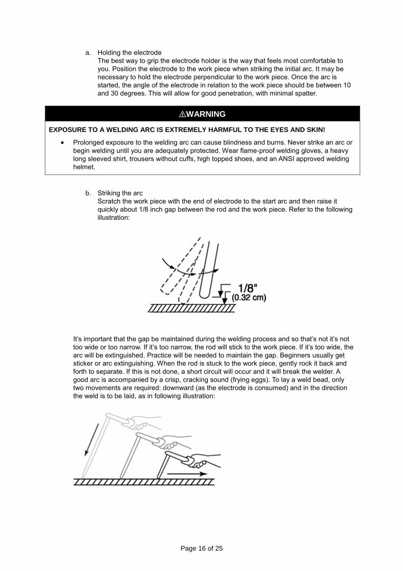
b. Striking the arc
Scratch the work piece with the end of electrode to the start arc and then raise it
quickly about 1/8 inch gap between the rod and the work piece. Refer to the following
illustration:
It’s important that the gap be maintained during the welding process and so that’s not it’s not
too wide or too narrow. If it’s too narrow, the rod will stick to the work piece. If it’s too wide, the
arc will be extinguished. Practice will be needed to maintain the gap. Beginners usually get
sticker or arc extinguishing. When the rod is stuck to the work piece, gently rock it back and
forth to separate. If this is not done, a short circuit will occur and it will break the welder. A
good arc is accompanied by a crisp, cracking sound (frying eggs). To lay a weld bead, only
two movements are required: downward (as the electrode is consumed) and in the direction
the weld is to be laid, as in following illustration:

Page 17 of 25
c. Types of weld bead
The following paragraphs discuss the most commonly used arc welding beads.
The stringer bead is formed by traveling with the electrode in a straight line while
keeping the electrode centered over the weld joint.
The weave bead is used when you want to deposit metal over a wider space than
would be possible with a stringer bead. It’s made by weaving from side to side while
moving with the electrode. It’s best to hesitate momentarily at each side before
weaving back the other way.
d. Welding position
The flat position is the easiest of the welding positions and the most commonly used.
It’s best if you can weld in the flat position, if at all possible, as good results are easier
to achieve.
The horizontal position is performed very much the same as the flat weld except that
the angle is different. The electrode and the arc force are directed more toward the
metal, above the weld joint. The more direct angle helps prevent the weld puddle
from running downward while still allowing slow enough travel speed to achieve good
penetration. A good starting point for your electrode angle is about 30 degrees DOWN
from being perpendicular to the work piece.
e. Judging the good weld bead
When you’ve learned to establish and to hold an arc, the next step is learning how to
run a good bead. The first attempts will probably fall short of acceptable weld beads.
Too long of an arc will be held or the travel speed will vary from slow to fast. See the
following illustration:
A. Weld speed is too fast.
B. Weld speed is too slow.
C. Arc is too long.
D. Ideal weld.
Stringer Bead Weave Bead
Flat Position Horizontal Position

Page 18 of 25
A solid weld bead requires that the electrode be moved slowly and steadily along the
weld seam. Moving the electrode rapidly or erratically will prevent proper fusion or
create a lumpy, uneven bead.
⚠WARNING
ELECTRIC SHOCK CAN KILL!
To prevent ELECTRIC SHOCK, do not perform any welding while standing, kneeling, or lying directly on the grounded workpiece.
f. Finish the bead As the coating on the outside of the electrode burns off, it forms an envelope of protective gases around the weld. This prevents air from reaching the molten metal and creating an undesirable chemical reaction. The burning coating, however, forms slag. The slag formation appears as an accumulation of dirty metal scale on the finished weld. Slag should be removed by using a chipping hammer.
⚠WARNING
PEENING THE SLAG FROM A WELD JOINT CUASES SMALL CHIPS OF METAL TO FLY
THROUGH THE AIR!
Metallic chips flying through the air can cause eye injury or injury to other parts of the head, hands, or exposed portions of the body. Wear goggles or safety glasses with side shields and protect the hands and other exposed parts of the body with protective garments, or if possible, work with a shield between the body and the work piece.
The intense heat produced at the arc sets up strains in the metal joined by welding.
Peening the weld not only removes the scale left behind in the welding but relieves
the internal strains developed by the heating and cooling process.
DC TIG OPERATION
⚠WARNING
High voltage danger from power source!
Consult a qualified electrician for proper installation of receptacle at the power source. This
welder must be grounded while in use to protect the operator from electrical shock. If you are
not sure if your outlet is properly grounded, have it checked by a qualified electrician. Do not
cut off the grounding prong or alter the plug in any way and do not use any adapter, other than
the supplied adapter, between the welder's power cord and the power source receptacle.
Make sure the POWER switch is OFF then connect your welder's power cord to a properly
grounded 120 VAC (110V-130V), 60 Hz, single phase, 20 amp power source.
⚠WARNING
EXPOSURE TO A WELDING ARC IS EXTREMELY HARMFUL TO THE EYES AND SKIN!
Prolonged exposure to the welding arc can cause blindness and burns. Never strike an arc or
begin welding until you are adequately protected. Wear flame-proof welding gloves, a heavy
long sleeved shirt, trousers without cuffs, high topped shoes, and an ANSI approved welding
helmet.

Page 19 of 25
⚠CAUTION
Be aware that the TIG torch will be electrically HOT when the Input Power Switch on the welder is
turned ON.
1. Remove the ground cable and the electrode holder from the weld output connections. Install
the ground cable to the positive (+) weld output connection.
2. Secure the ground clamp to the work piece
3. Connect a regulator to a bottle of ARGON gas, then connect the gas connection from the TIG
torch to the regulator.
4. Connect the TIG torch weld cable to the negative (-) weld output connection.
5. Set the desired amperage on the amperage control knob on the front panel of the welder.
6. Turn ON the input power switch on the welder.
7. Turn ON the regulator on the bottle of shielding gas and adjust the regulator to approximately
20 CFH, then open the shielding gas valve on the torch to start the flow of shielding gas.
8. Follow these steps for striking an arc while TIG welding.
8.1 Open the shielding gas valve on the torch handle to start the gas flow.
8.2 Rest the TIG torch nozzle on the work piece taking care not to touch the installed tungsten
electrode.
8.3 Twist the torch to make contact between the work piece and the tungsten. 8.4 Lift the torch away from the work piece about 1/8 inch.
8.5 Move the joint down for welding by pushing the torch. 8.6 Insert the filler metal in the leading edge of the weld puddle as needed.
Maintenance
⚠WARNING
ELECTRIC SHOCK CAN KILL!
Touching live electrical parts can cause fatal shocks or severe burns. Do not touch live
electrical parts
Wear dry, hole-free insulating gloves and body protection.
Disconnect input power before installing, maintaining, or servicing this equipment.
Lockout/tagout input power according to OSHA 29 CFR 1910.147.
Page 20 of 25
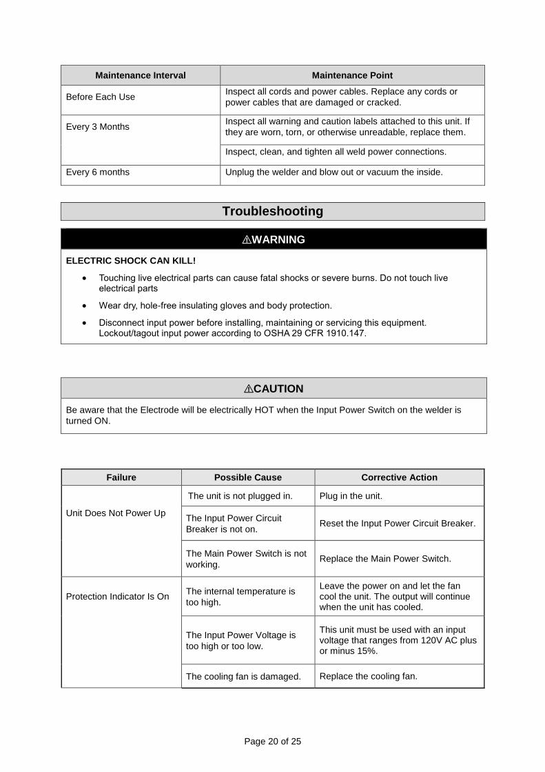
Maintenance Interval Maintenance Point
Before Each Use Inspect all cords and power cables. Replace any cords or
power cables that are damaged or cracked.
Every 3 Months Inspect all warning and caution labels attached to this unit. If
they are worn, torn, or otherwise unreadable, replace them.
Inspect, clean, and tighten all weld power connections.
Every 6 months Unplug the welder and blow out or vacuum the inside.
Troubleshooting
⚠WARNING
ELECTRIC SHOCK CAN KILL!
Touching live electrical parts can cause fatal shocks or severe burns. Do not touch live electrical parts
Wear dry, hole-free insulating gloves and body protection.
Disconnect input power before installing, maintaining or servicing this equipment. Lockout/tagout input power according to OSHA 29 CFR 1910.147.
⚠CAUTION
Be aware that the Electrode will be electrically HOT when the Input Power Switch on the welder is
turned ON.
Failure Possible Cause Corrective Action
Unit Does Not Power Up
The unit is not plugged in. Plug in the unit.
The Input Power Circuit
Breaker is not on. Reset the Input Power Circuit Breaker.
The Main Power Switch is not
working. Replace the Main Power Switch.
Protection Indicator Is On The internal temperature is
too high.
Leave the power on and let the fan cool the unit. The output will continue when the unit has cooled.
The Input Power Voltage is
too high or too low.
This unit must be used with an input voltage that ranges from 120V AC plus or minus 15%.
The cooling fan is damaged. Replace the cooling fan.

Page 21 of 25
Failure Possible Cause Corrective Action
Cannot Create an Arc Work piece is painted or rusty. Remove all paint and rust.
Ground clamp is connected
where there is paint or rust.
Remove all paint and rust so the ground clamp is connected to bare metal.
Ground clamp is not
electrically connected to the
work piece.
Make sure the ground clamp is connected to the work piece.
The Process Selector Switch
is in the wrong positon.
Make sure the Stick/TIG selector switch is in the STICK position.
Electrode Holder or Ground Cable is Getting Hot. Output Connections are Getting Hot
Weld cable connections are
loose.
Check to make sure weld cables are tight.
Weld cable connections have
corroded. Clean weld connections and reinstall.
Poor Welding Performance. Excessive Spatter
Damp electrode. Use fresh and dry electrodes.
Electrode Sticks The electrode is kept in
contact with the work piece for
too long while striking an arc.
This will take practice; keep trying.
Welding Bead Is Too Thin The welding travel speed is
too fast.
Reduce the welding travel speed. Incorporate a slight weave over the joint.
Welding Bead Is Too Thick The welding travel speed is
too slow. Increase the welding travel speed.
For Assistance, Contact the Welder Help Line at 877-304-0294

Page 22 of 25
Parts Diagram

Page 23 of 25
Parts List
Reference Part Number Item Description Quantity
1 105300064 HANDLE 1
NOT SHOWN 105300065 SHOULDER STRAP 1
2 125300008 ENCLOSURE 1
3 105200037 INPUT POWER SWITCH 1
4 105300022 INPUT POWER CORD 1
5 105300066 BACK PANEL BEZEL 1
6 105300067 FAN SUPPORT 1
7 105300019 BOX FAN 1
8 105300016 IGBT 4
9 105300068 HEAT SINK 1
10 105300017 HEAT SINK 2
11 105300018 HEAT SINK SUPPORT 1
12 105300015 HEAT SINK 1
13 105300013 DIODE 4
14 105300069 MAIN PC BOARD 1
15 105300070 BOTTOM 1
16 105300071 FRONT PANEL PC BOARD 1
17 105300072 QUICK CONNECT RECEPTACLE 2
18 105300073 FRONT PANEL BEZEL 1
125300009 FRONT NAMEPLATE ST80i PLUS 1
19 105200063 POTENTIOMETER KNOB 1
20 105300007 GROUND CABLE AND CLAMP 1
105300074 GROUND CLAMP ONLY 1
21 105300009 ELECTRODE HOLDER AND CABLE 1
105300010 ELECTRODE HOLDER ONLY 1
125300002 OPERATOR’S MANUAL 1
Replacement Parts
For replacement parts and technical questions, please call Customer Service at 1-800-222-5381.
Not all product components are available for replacement. The illustrations provided are a
convenient reference to the location and position of parts in the assembly sequence.
When ordering parts, the following information will be required: item description, item model
number, item serial number/item lot date code, and the replacement part reference number.
The distributor reserves the rights to make design changes and improvements to product lines
and manuals without notice.

Page 24 of 25
Limited Warranty
Northern Tool and Equipment Company, Inc. ("We'' or "Us'') warrants to the original purchaser only
("You'' or ''Your'') that the Klutch product purchased will be free from material defects in both materials
and workmanship, normal wear and tear excepted, for a period of three years from date of purchase.
The foregoing warranty is valid only if the installation and use of the product is strictly in accordance
with product instructions. There are no other warranties, express or implied, including the warranty of
merchantability or fitness for a particular purpose. If the product does not comply with this limited
warranty, Your sole and exclusive remedy is that We will, at our sole option and within a commercially
reasonable time, either replace the product or product component without charge to You or refund the
purchase price (less shipping). This limited warranty is not transferable.
Limitations on the Warranty
This limited warranty does not cover: (a) normal wear and tear; (b) damage through abuse, neglect,
misuse, or as a result of any accident or in any other manner; (c) damage from misapplication,
overloading, or improper installation; (d) improper maintenance and repair; and (e) product alteration
in any manner by anyone other than Us, with the sole exception of alterations made pursuant to
product instructions and in a workmanlike manner.
Obligations of Purchaser
You must retain Your product purchase receipt to verify date of purchase and that You are the original
purchaser. To make a warranty claim, contact Us at 1-800-222-5381, identify the product by make
and model number, and follow the claim instructions that will be provided. The product and the
purchase receipt must be provided to Us in order to process Your warranty claim. Any returned
product that is replaced or refunded by Us becomes our property. You will be responsible for return
shipping costs or costs related to Your return visit to a retail store.
Remedy Limits
Product replacement or a refund of the purchase price is Your sole remedy under this limited warranty
or any other warranty related to the product. We shall not be liable for: service or labor charges or
damage to Your property incurred in removing or replacing the product; any damages, including,
without limitation, damages to tangible personal property or personal injury, related to Your improper
use, installation, or maintenance of the product or product component; or any indirect, incidental or
consequential damages of any kind for any reason.
Assumption of Risk
You acknowledge and agree that any use of the product for any purpose other than the specified
use(s) stated in the product instructions is at Your own risk.
Governing Law
This limited warranty gives You specific legal rights, and You also may have other rights which vary
from state to state. Some states do not allow limitations or exclusions on implied warranties or
incidental or consequential damages, so the above limitations may not apply to You. This limited
warranty is governed by the laws of the State of Minnesota, without regard to rules pertaining to
conflicts of law. The state courts located in Dakota County, Minnesota shall have exclusive jurisdiction
for any disputes relating to this warranty.

Page 25 of 25
Distributed by:
Northern Tool & Equipment Company, Inc.
Burnsville, Minnesota 55306
www.northerntool.com
Made in China