inverter arc welder - esab welding & cutting equipment/welding packages... · inverter arc...
TRANSCRIPT
INVERTERARC
WELDER
MODEL 300GTSW AC/DC CC/TIG• STICK• TIG - HIGH FREQUENCY
- LIFT START
OPERATING MANUAL
July 1, 1997
TM
R
Manual No. 0-2514
TABLE OF CONTENTS
1.0 GENERAL INFORMATION ........................................................ 2
1.01 Notes, Cautions and Warnings ................................................. 2
1.02 Important Safety Precautions .................................................... 31.03 Publications ................................................................................. 6
1.04 Note, Attention et Avertissement ............................................. 71.05 Precautions De Securite Importantes....................................... 8
1.06 Documents De Reference......................................................... 11
1.07 Declaration of Conformity ...................................................... 121.08 Statement of Warranty ............................................................. 13
2.0 INTRODUCTION AND DESCRIPTION ................................ 15
2.01 Description ................................................................................ 152.02 Functional Block Diagram ....................................................... 16
2.03 Transporting Methods.............................................................. 172.04 Electrical Input Connections ................................................... 17
2.05 Specifications ............................................................................. 19
2.06 Duty Cycle ................................................................................. 20
3.0 OPERATOR CONTROLS ........................................................... 21
3.01 Front and Rear panel operator controls ................................ 21
3.02 Setup for Operation .................................................................. 23Shielded Metal Arc Welding (SMAW) ........................................ 24
Gas Tungsten Arc Welding (GTAW)High Frequency/Lift Start ........................................................... 26
(Gas Tungsten Arc Welding-Pulsed (GTAW-P)-Sloped (GTAW-S) -TIG Spot ....................................................... 28
4.0 BASIC TROUBLESHOOTING .................................................. 31
4.01 Common Welding Operation Faults ...................................... 31
4.02 Specific Problems ...................................................................... 314.03 REMOTE 8-Pin Connections ................................................... 36
APPENDIX A – ACCESSORIES ...................................................... 38
APPENDIX B – INTERCONNECTION DIAGRAMS................. 41
1 GENERALMANUAL 0-2514
WARNING Read and understand this entire Operating Manual and youremployer’s safety practices before installing, operating, or servicingthe equipment.
WARNING While the information contained in this Operating Manual representsour best judgement, Thermal Dynamics Corporation assumes noliability for its use.
Thermal Arc Models 300GTSW AC/DC CC/TIG WelderOperating Manual Number 0-2514
Published by:Thermal Dynamics CorporationIndustrial Park No. 2West Lebanon, New Hampshire, USA 03784(603) 298-5711
Copyright 1997 byThermal Dynamics Corporation
All rights reserved.
Reproduction of this work, in whole or in part, without writtenpermission of the publisher is prohibited.
The publisher does not assume and hereby disclaims any liability to anyparty for any loss or damage caused by any error or omission in thisOperating Manual, whether such error results from negligence,accident, or any other cause.
Printed in the United States of America
July 1, 1997
2GENERAL MANUAL 0-2514
1.0 GENERAL INFORMATION
1.01 NOTES, CAUTIONS AND WARNINGS
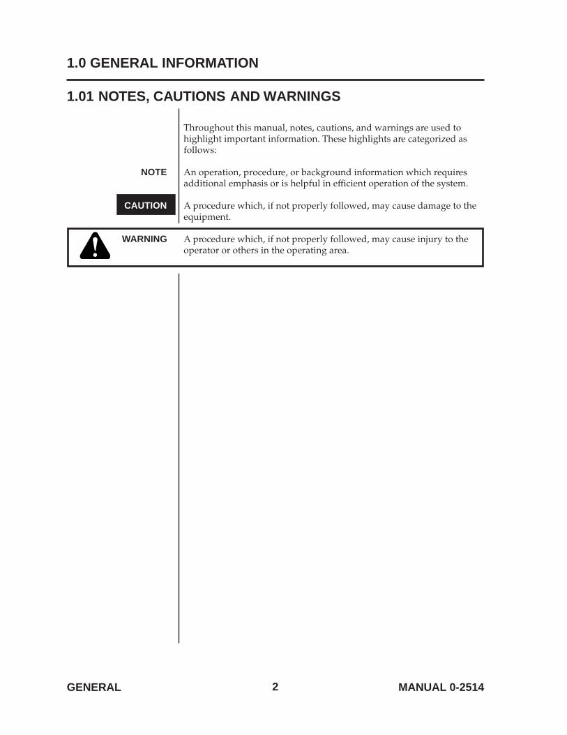
Throughout this manual, notes, cautions, and warnings are used tohighlight important information. These highlights are categorized asfollows:
NOTE An operation, procedure, or background information which requiresadditional emphasis or is helpful in efficient operation of the system.
CAUTION A procedure which, if not properly followed, may cause damage to theequipment.
WARNING A procedure which, if not properly followed, may cause injury to theoperator or others in the operating area.
3 GENERALMANUAL 0-2514
WARNING1.02 IMPORTANT SAFETY PRECAUTIONSOPERATION AND MAINTENANCE OF PLASMA ARC EQUIPMENT
CAN BE DANGEROUS AND HAZARDOUS TO YOUR HEALTH.
To prevent possible injury, read, understand and follow all warnings, safety precautions andinstructions before using the equipment. Call 1-603-298-5711 or your local distributor if you have anyquestions.
GASES AND FUMES Gases and fumes produced during the plasma cutting process can bedangerous and hazardous to your health.
• Keep all fumes and gases from the breathing area. Keep your head outof the welding fume plume.
• Use an air-supplied respirator if ventilation is not adequate to removeall fumes and gases.
• The kinds of fumes and gases from the plasma arc depend on the kindof metal being used, coatings on the metal, and the differentprocesses. You must be very careful when cutting or welding anymetals which may contain one or more of the following:
Antimony Chromium MercuryArsenic Cobalt NickelBarium Copper SeleniumBeryllium Lead SilverCadmium Manganese Vanadium
• Always read the Material Safety Data Sheets (MSDS) that should besupplied with the material you are using. These MSDSs will give youthe information regarding the kind and amount of fumes and gasesthat may be dangerous to your health.
• For information on how to test for fumes and gases in yourworkplace, refer to item 1 in the Publications Section in this manual.
• Use special equipment, such as water or down draft cutting tables, tocapture fumes and gases.
• Do not use the plasma torch in an area where combustible orexplosive gases or materials are located.
• Phosgene, a toxic gas, is generated from the vapors of chlorinatedsolvents and cleansers. Remove all sources of these vapors.
4GENERAL MANUAL 0-2514
IMPORTANT SAFETY PRECAUTIONS (CONTINUED)
ELECTRIC SHOCK Electric Shock can injure or kill. The plasma arc process uses andproduces high voltage electrical energy. This electric energy can causesevere or fatal shock to the operator or others in the workplace.
• Never touch any parts that are electrically “live” or “hot.”
• Wear dry gloves and clothing. Insulate yourself from the work pieceor other parts of the welding circuit.
• Repair or replace all worn or damaged parts.
• Extra care must be taken when the workplace is moist or damp.
• Install and maintain equipment according to NEC code, refer to item 4in the Publications section of this manual.
• Disconnect power source before performing any service or repairs.
• Read and follow all the instructions in the Operating Manual.
FIRE AND EXPLOSION Fire and explosion can be caused by hot slag, sparks, or the plasma arc.
• Be sure there is no combustible or flammable material in theworkplace. Any material that cannot be removed must be protected.
• Ventilate all flammable or explosive vapors from the workplace.
• Do not cut or weld on containers that may have held combustibles.
• Provide a fire watch when working in an area where fire hazards mayexist.
• Hydrogen gas may be formed and trapped under aluminumworkpieces when they are cut underwater or while using a watertable. DO NOT cut aluminum alloys underwater or on a water tableunless the hydrogen gas can be eliminated or dissipated. Trappedhydrogen gas that is ignited will cause an explosion.
NOISE Noise can cause permanent hearing loss. Plasma arc processes can causenoise levels to exceed safe limits. You must protect your ears from loudnoise to prevent permanent loss of hearing.
• To protect your hearing from loud noise, wear protective ear plugsand/or ear muffs. Protect others in the workplace.
• Noise levels should be measured to be sure the decibels (sound) donot exceed safe levels.
• For information on how to test for noise, see item 1 in the Publicationssection of this manual.
5 GENERALMANUAL 0-2514
IMPORTANT SAFETY PRECAUTIONS (CONTINUED)
PLASMA ARC RAYS Plasma Arc Rays can injure your eyes and burn your skin. The plasmaarc process produces very bright ultra violet and infra red light. Thesearc rays will damage your eyes and burn your skin if you are notproperly protected.
• To protect your eyes, always wear a welding helmet or shield. Alsoalways wear safety glasses with side shields, goggles or otherprotective eye wear.
• Wear welding gloves and suitable clothing to protect your skin fromthe arc rays and sparks.
• Keep helmet and safety glasses in good condition. Replace lenseswhen cracked, chipped or dirty.
• Protect others in the work area from the arc rays. Use protectivebooths, screens or shields.
• Use the shade of lens as recommended in the Operating Manual.
6GENERAL MANUAL 0-2514
1.03 PUBLICATIONS
Refer to the following standards or their latest revisions for more information:
1. OSHA, SAFETY AND HEALTH STANDARDS, 29CFR 1910, obtainable from the Superintendentof Documents, U.S. Government Printing Office, Washington, D.C. 20402
2. ANSI Standard Z49.1, SAFETY IN WELDING AND CUTTING, obtainable from the AmericanWelding Society, 550 N.W. LeJeune Rd, Miami, FL 33126
3. NIOSH, SAFETY AND HEALTH IN ARC WELDING AND GAS WELDING AND CUTTING,obtainable from the Superintendent of Documents, U.S. Government Printing Office,Washington, D.C. 20402
4. ANSI Standard Z87.1, SAFE PRACTICES FOR OCCUPATION AND EDUCATIONAL EYE ANDFACE PROTECTION, obtainable from American National Standards Institute, 1430 Broadway,New York, NY 10018
5. ANSI Standard Z41.1, STANDARD FOR MEN’S SAFETY-TOE FOOTWEAR, obtainable from theAmerican National Standards Institute, 1430 Broadway, New York, NY 10018
6. ANSI Standard Z49.2, FIRE PREVENTION IN THE USE OF CUTTING AND WELDINGPROCESSES, obtainable from American National Standards Institute, 1430 Broadway, New York,NY 10018
7. AWS Standard A6.0, WELDING AND CUTTING CONTAINERS WHICH HAVE HELDCOMBUSTIBLES, obtainable from American Welding Society, 550 N.W. LeJeune Rd, Miami, FL33126
8. NFPA Standard 51, OXYGEN-FUEL GAS SYSTEMS FOR WELDING, CUTTING AND ALLIEDPROCESSES, obtainable from the National Fire Protection Association, Batterymarch Park,Quincy, MA 02269
9. NFPA Standard 70, NATIONAL ELECTRICAL CODE, obtainable from the National FireProtection Association, Batterymarch Park, Quincy, MA 02269
10. NFPA Standard 51B, CUTTING AND WELDING PROCESSES, obtainable from the National FireProtection Association, Batterymarch Park, Quincy, MA 02269
11. CGA Pamphlet P-1, SAFE HANDLING OF COMPRESSED GASES IN CYLINDERS, obtainablefrom the Compressed Gas Association, 1235 Jefferson Davis Highway, Suite 501, Arlington, VA22202
12. CSA Standard W117.2, CODE FOR SAFETY IN WELDING AND CUTTING, obtainable from theCanadian Standards Association, Standards Sales, 178 Rexdale Boulevard, Rexdale, Ontario,Canada M9W 1R3
13. NWSA booklet, WELDING SAFETY BIBLIOGRAPHY obtainable from the National WeldingSupply Association, 1900 Arch Street, Philadelphia, PA 19103
14. American Welding Society Standard AWSF4.1, RECOMMENDED SAFE PRACTICES FOR THEPREPARATION FOR WELDING AND CUTTING OF CONTAINERS AND PIPING THAT HAVEHELD HAZARDOUS SUBSTANCES, obtainable from the American Welding Society, 550 N.W.LeJeune Rd, Miami, FL 33126
15. ANSI Standard Z88.2, PRACTICE FOR RESPIRATORY PROTECTION, obtainable fromAmerican National Standards Institute, 1430 Broadway, New York, NY 10018
7 GENERALMANUAL 0-2514
1.04 NOTE, ATTENTION ET AVERTISSEMENT
Dans ce manuel, les mots “note,” “attention,” et “avertissement” sontutilisés pour mettre en relief des informations à caractère important. Cesmises en relief sont classifiées comme suit :
NOTET oute opération, procédure ou renseignement général sur lequel ilimporte d’insister davantage ou qui contribue à l’efficacité defonctionnement du système.
ATTENTION Toute procédure pouvant résulter l’endommagement du matériel en casde non-respect de la procédure en question.
AVERTISSEMENT Toute procédure pouvant provoquer des blessures de l’opérateurou des autres personnes se trouvant dans la zone de travail en cas denon-respect de la procédure en question.
8GENERAL MANUAL 0-2514
AVERTISSEMENT1.05 PRECAUTIONS DE SECURITE IMPORTANTES
L’OPÉRATION ET LA MAINTENANCE DU MATÉRIEL DE SOUDAGEÀ L’ARC AU JET DE PLASMA PEUVENT PRÉSENTER
DES RISQUES ET DES DANGERS DE SANTÉ.Il faut communiquer aux opérateurs et au personnel TOUS les dangers possibles. Afin d’éviter lesblessures possibles, lisez, comprenez et suivez tous les avertissements, toutes les précautions desécurité et toutes les consignes avant d’utiliser le matériel. Composez le + 603-298-5711 ou votredistributeur local si vous avez des questions.
FUMÉE et GAZ La fumée et les gaz produits par le procédé de jet de plasma peuventprésenter des risques et des dangers de santé.
• Eloignez toute fumée et gaz de votre zone de respiration. Gardez votretête hors de la plume de fumée provenant du chalumeau.
• Utilisez un appareil respiratoire à alimentation en air si l’aérationfournie ne permet pas d’éliminer la fumée et les gaz.
• Les sortes de gaz et de fumée provenant de l’arc de plasma dépendentdu genre de métal utilisé, des revêtements se trouvant sur le métal etdes différents procédés. Vous devez prendre soin lorsque vous coupezou soudez tout métal pouvant contenir un ou plusieurs des élémentssuivants:
antimoine cadmium mercureargent chrome nickelarsenic cobalt plombbaryum cuivre séléniumbéryllium manganèse vanadium
• Lisez toujours les fiches de données sur la sécurité des matières (sigleaméricain “MSDS”); celles-ci devraient être fournies avec le matérielque vous utilisez. Les MSDS contiennent des renseignements quant àla quantité et la nature de la fumée et des gaz pouvant poser desdangers de santé.
• Pour des informations sur la manière de tester la fumée et les gaz devotre lieu de travail, consultez l’article 1 et les documents cités à lapage 11.
• Utilisez un équipement spécial tel que des tables de coupe à débitd’eau ou à courant descendant pour capter la fumée et les gaz.
• N’utilisez pas le chalumeau au jet de plasma dans une zone où setrouvent des matières ou des gaz combustibles ou explosifs.
• Le phosgène, un gaz toxique, est généré par la fumée provenant dessolvants et des produits de nettoyage chlorés. Eliminez toute sourcede telle fumée.
9 GENERALMANUAL 0-2514
PRECAUTIONS DE SECURITE IMPORTANTES
CHOC ELECTRIQUE Les chocs électriques peuvent blesser ou même tuer. Le procédé au jetde plasma requiert et produit de l’énergie électrique haute tension. Cetteénergie électrique peut produire des chocs graves, voire mortels, pourl’opérateur et les autres personnes sur le lieu de travail.
• Ne touchez jamais une pièce “sous tension” ou “vive”; portez desgants et des vêtements secs. Isolez-vous de la pièce de travail ou desautres parties du circuit de soudage.
• Réparez ou remplacez toute pièce usée ou endommagée.
• Prenez des soins particuliers lorsque la zone de travail est humide oumoite.
• Montez et maintenez le matériel conformément au Code électriquenational des Etats-Unis. (Voir la page 6, article 9.)
• Débranchez l’alimentation électrique avant tout travail d’entretien oude réparation.
• Lisez et respectez toutes les consignes du Manuel de consignes.
INCENDIE ETEXPLOSION Les incendies et les explosions peuvent résulter des scories chaudes, des
étincelles ou de l’arc de plasma. Le procédé à l’arc de plasma produit dumétal, des étincelles, des scories chaudes pouvant mettre le feu auxmatières combustibles ou provoquer l’explosion de fuméesinflammables.
• Soyez certain qu’aucune matière combustible ou inflammable ne setrouve sur le lieu de travail. Protégez toute telle matière qu’il estimpossible de retirer de la zone de travail.
• Procurez une bonne aération de toutes les fumées inflammables ouexplosives.
• Ne coupez pas et ne soudez pas les conteneurs ayant pu renfermer desmatières combustibles.
• Prévoyez une veille d’incendie lors de tout travail dans une zoneprésentant des dangers d’incendie.
• Le gas hydrogène peut se former ou s’accumuler sous les pièces detravail en aluminium lors’quelles sont coupeés sous l’eau ou sur unetable d’eau. NE PAS couper les alliages en aluminium sous l’eau ousur une table d’eau à mains que le gas hydrogène peut s’échapper ouse dissiper. Le gas hydrogène accumulé explosera si enflammé.
10GENERAL MANUAL 0-2514
PRECAUTIONS DE SECURITE IMPORTANTES
RAYONS D’ARCDE PLASMA Les rayons provenant de l’arc de plasma peuvent blesser vos yeux et
brûler votre peau. Le procédé à l’arc de plasma produit une lumièreinfra-rouge et des rayons ultra-violets très forts. Ces rayons d’arcnuiront à vos yeux et brûleront votre peau si vous ne vous protégez pascorrectement.
• Pour protéger vos yeux, portez toujours un casque ou un écran desoudeur. Portez toujours des lunettes de sécurité munies de paroislatérales ou des lunettes de protection ou une autre sorte de protectionoculaire.
• Portez des gants de soudeur et un vêtement protecteur appropriépour protéger votre peau contre les étincelles et les rayons de l’arc.
• Maintenez votre casque et vos lunettes de protection en bon état.Remplacez toute lentille sale ou comportant fissure ou rognure.
• Protégez les autres personnes se trouvant sur la zone de travail contreles rayons de l’arc en fournissant des cabines ou des écrans deprotection.
• Respectez le teint de lentille recommandé dans le manuel deconsignes.
BRUIT Le bruit peut provoquer une perte permanente de l’ouïe. Les procédésde soudage à l’arc de plasma peuvent provoquer des niveaux sonoressupérieurs aux limites normalement acceptables. Vous dúvez vousprotéger les oreilles contre les bruits forts afin d’éviter une pertepermanente de l’ouïe.
• Pour protéger votre ouïe contre les bruits forts, portez des tamponsprotecteurs et/ou des protections auriculaires. Protégez également lesautres personnes se trouvant sur le lieu de travail.
• Il faut mesurer les niveaux sonores afin d’assurer que les décibels (lebruit) ne dépassent pas les niveaux sûrs.
• Pour des renseignements sur la manière de tester le bruit, consultezl’article 1, page 11.
11 GENERALMANUAL 0-2514
1.06 DOCUMENTS DE REFERENCE
Consultez les normes suivantes ou les révisions les plus récentes ayant été faites à celles-ci pour de plusamples renseignements :
1. OSHA, NORMES DE SÉCURITÉ DU TRAVAIL ET DE PROTECTION DE LA SANTÉ, 29CFR1910, disponible auprès du Superintendent of Documents, U.S. Government Printing Office,Washington, D.C. 20402
2. Norme ANSI Z49.1, LA SÉCURITÉ DES OPÉRATIONS DE COUPE ET DE SOUDAGE,disponible auprès de la Société Américaine de Soudage (American Welding Society), 550 N.W.LeJeune Rd., Miami, FL 33126
3. NIOSH, LA SÉCURITÉ ET LA SANTÉ LORS DES OPÉRATIONS DE COUPE ET DE SOUDAGEÀ L’ARC ET AU GAZ, disponible auprès du Superintendent of Documents, U.S. GovernmentPrinting Office, Washington, D.C. 20402
4. Norme ANSI Z87.1, PRATIQUES SURES POUR LA PROTECTION DES YEUX ET DU VISAGEAU TRAVAIL ET DANS LES ECOLES, disponible de l’Institut Américain des Normes Nationales(American National Standards Institute), 1430 Broadway, New York, NY 10018
5. Norme ANSI Z41.1, NORMES POUR LES CHAUSSURES PROTECTRICES, disponible auprès del’American National Standards Institute, 1430 Broadway, New York, NY 10018
6. Norme ANSI Z49.2, PRÉVENTION DES INCENDIES LORS DE L’EMPLOI DE PROCÉDÉS DECOUPE ET DE SOUDAGE, disponible auprès de l’American National Standards Institute, 1430Broadway, New York, NY 10018
7. Norme A6.0 de l’Association Américaine du Soudage (AWS), LE SOUDAGE ET LA COUPE DECONTENEURS AYANT RENFERMÉ DES PRODUITS COMBUSTIBLES, disponible auprès de laAmerican Welding Society, 550 N.W. LeJeune Rd., Miami, FL 33126
8. Norme 51 de l’Association Américaine pour la Protection contre les Incendies (NFPA), LESSYSTEMES À GAZ AVEC ALIMENTATION EN OXYGENE POUR LE SOUDAGE, LA COUPEET LES PROCÉDÉS ASSOCIÉS, disponible auprès de la National Fire Protection Association,Batterymarch Park, Quincy, MA 02269
9. Norme 70 de la NFPA, CODE ELECTRIQUE NATIONAL, disponible auprès de la National FireProtection Association, Batterymarch Park, Quincy, MA 02269
10. Norme 51B de la NFPA, LES PROCÉDÉS DE COUPE ET DE SOUDAGE, disponible auprès de laNational Fire Protection Association, Batterymarch Park, Quincy, MA 02269
11. Brochure GCA P-1, LA MANIPULATION SANS RISQUE DES GAZ COMPRIMÉS ENCYLINDRES, disponible auprès de l’Association des Gaz Comprimés (Compressed GasAssociation), 1235 Jefferson Davis Highway, Suite 501, Arlington, VA 22202
12. Norme CSA W117.2, CODE DE SÉCURITÉ POUR LE SOUDAGE ET LA COUPE, disponibleauprès de l’Association des Normes Canadiennes, Standards Sales, 178 Rexdale Boulevard,Rexdale, Ontario, Canada, M9W 1R3
13. ivret NWSA, BIBLIOGRAPHIE SUR LA SÉCURITÉ DU SOUDAGE, disponible auprès del’Association Nationale de Fournitures de Soudage (National Welding Supply Association), 1900Arch Street, Philadelphia, PA 19103
14. Norme AWSF4.1 de l’Association Américaine de Soudage, RECOMMANDATIONS DEPRATIQUES SURES POUR LA PRÉPARATION À LA COUPE ET AU SOUDAGE DECONTENEURS ET TUYAUX AYANT RENFERMÉ DES PRODUITS DANGEREUX , disponibleauprès de la American Welding Society, 550 N.W. LeJeune Rd., Miami, FL 33126
15. Norme ANSI Z88.2, PRATIQUES DE PROTECTION RESPIRATOIRE, disponible auprès del’American National Standards Institute, 1430 Broadway, New York, NY 10018

12GENERAL MANUAL 0-2514
1.07 DECLARATION OF CONFORMITY
Manufacturer: Thermal Dynamics CorporationAddress: Industrial Park #2
West Lebanon, New Hampshire 03784USA
The equipment described in this manual conforms to all applicable aspects and regulations of the ‘LowVoltage Directive’ (European Council Directive 73/23/EU, as recently changed in Directive 93/63/EU)and to the National legislation for the enforcement of this Directive.
The equipment described in this manual conforms to all applicable aspects and regulations of the “EMCDirective” (European Council Directive 89/336/EEC) and to the National legislation for the enforcementof this Directive.
Serial numbers are unique with each individual piece of equipment and details description, parts used tomanufacture a unit and date of manufacture.
National Standard and Technical Specifications
The product is designed and manufactured to a number of standards and technical requirements amongthem are:
* CSA (Canadian Standards Association) standard C22.2 number 60-M1990 for Arc welding equipment.
* UL (Underwriters Laboratory) rating 94VO flammability testing for all printed-circuit boards used.
* CENELEC EN50199 EMC Product Standard for Arc Welding Equipment March 1995.
* IEC 974-1 (BS 638-PT10) (EN 60 974-1) applicable to welding equipment and associated accessories.
* Extensive product design verification is conducted at the manufacturing facility as part of the routinedesign and manufacturing process, to ensure the product is safe and performs as specified. Rigoroustesting is incorporated into the manufacturing process to ensure the manufactured product meets orexceeds all design specifications.
Thermal Dynamics has been manufacturing products that perform in a safe manner for more than 30years and will continue to achieve excellence in our area of manufacture.
Manufacturers responsible representative: David AshworthVice President & Managing DirectorThermadyne EuropeChorley England.
13 GENERALMANUAL 0-2514
1.08 STATEMENT OF WARRANTY
LIMITED WARRANTY: Thermal Dynamics Corporation (hereinafter “Thermal”) warrants that itsproducts will be free of defects in workmanship or material. Should any failure to conform to thiswarranty appear within the time period applicable to the Thermal products as stated below, Thermalshall, upon notification thereof and substantiation that the product has been stored, installed, operated,and maintained in accordance with Thermal’s specifications, instructions, recommen dations andrecognized standard industry practice, and not subject to misuse, repair, neglect, alteration, or accident,correct such defects by suitable repair or replacement, at Thermal’s sole option, of any components orparts of the product determined by Thermal to be defective.
THIS WARRANTY IS EXCLUSIVE AND IS IN LIEU OF ANY WARRANTY OF MERCHANTABILITYOR FITNESS FOR A PARTICULAR PURPOSE.
LIMITATION OF LIABILITY: Thermal shall not under any circumstances be liable for special orconsequential damages, such as, but not limited to, damage or loss of purchased or replacement goods,or claims of customers of distributor (hereinafter “Purchaser”) for service interruption. The remedies ofthe Purchaser set forth herein are exclusive and the liability of Thermal with respect to any contract, oranything done in connection therewith such as the performance or breach thereof, or from themanufacture, sale, delivery, resale, or use of any goods covered by or furnished by Thermal whetherarising out of contract, negligence, strict tort, or under any warranty, or otherwise, shall not, except asexpressly provided herein, exceed the price of the goods upon which such liability is based.
THIS WARRANTY BECOMES INVALID IF REPLACEMENT PARTS OR ACCESSORIES ARE USEDWHICH MAY IMPAIR THE SAFETY OR PERFORMANCE OF ANY THERMAL PRODUCT.
THIS WARRANTY IS INVALID IF THE PRODUCT IS SOLD BY NON-AUTHORIZED PERSONS.
The limited warranty periods for Thermal products shall be as follows: A maximum of three (3) yearsfrom date of sale to an authorized distributor and a maximum of two (2) years from date of sale by suchdistributor to the Purchaser, and with the following further limitations on such two (2) year period:
PAK UNITS, POWER SUPPLIES␣ PARTS␣ LABOR
MAIN POWER MAGNETICS........................................ 2 YEARS................... 1 YEAR
ORIGINAL MAIN POWER RECTIFIER ....................... 2 YEARS................... 1 YEAR
CONTROL PC BOARD .................................................. 2 YEARS................... 1 YEAR
ALL OTHER CIRCUITS AND COMPONENTS ........... 1 YEAR.................... 1 YEAR
INCLUDING, BUT NOT LIMITED TO, STARTING
CIRCUIT, CONTACTORS, RELAYS, SOLENOIDS,PUMPS, POWER SWITCHING SEMI-CONDUCTORS
CONSOLES, CONTROL EQUIPMENT, HEAT ......................1 YEAR.................... 1 YEAR
EXCHANGES, AND ACCESSORY EQUIPMENT
TORCH AND LEADS ............................................................180 DAYS ................ 180 DAYS
REPAIR/REPLACEMENT PARTS ......................................... 90 DAYS .................. 90 DAYS
Warranty repairs or replacement claims under this limited warranty must be submitted by an authorizedThermal Arc® repair facility within thirty (30) days of the repair. Authorized Thermal Arc® repair facilitiesare authorized distributors and authorized Thermal Arc® Service Centers. No transportation costs of anykind will be paid under this warranty. Transportation charges to send products to an authorizedwarranty repair facility shall be the responsibility of the customer. All returned goods shall be at thecustomer’s risk and expense. This warranty supersedes all previous Thermal warranties.
Thermal Arc® is a Registered Trademark of Thermal Dynamics.
Effective January 18, 1991

14 MANUAL 0-2514
15MANUAL 0-2514 INTRODUCTION
2.0 INTRODUCTION AND DESCRIPTION
2.01 Description
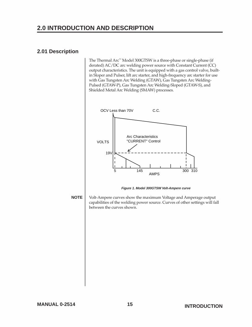
The Thermal Arc™ Model 300GTSW is a three-phase or single-phase (ifderated) AC/DC arc welding power source with Constant Current (CC)output characteristics. The unit is equipped with a gas control valve, built-in Sloper and Pulser, lift arc starter, and high-frequency arc starter for usewith Gas Tungsten Arc Welding (GTAW), Gas Tungsten Arc Welding-Pulsed (GTAW-P), Gas Tungsten Arc Welding-Sloped (GTAW-S), andShielded Metal Arc Welding (SMAW) processes.
19V
3005AMPS
VOLTSArc Characteristics"CURRENT" Control
310145
OCV Less than 70V C.C.
Figure 1. Model 300GTSW Volt-Ampere curve
NOTE Volt-Ampere curves show the maximum Voltage and Amperage outputcapabilities of the welding power source. Curves of other settings will fallbetween the curves shown.
16 MANUAL 0-2514
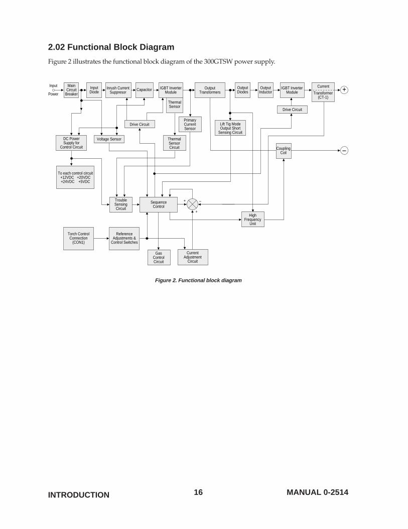
2.02 Functional Block Diagram
Figure 2 illustrates the functional block diagram of the 300GTSW power supply.
MainCircuit
Breaker
DC PowerSupply for
Control Circuit
Voltage Sensor
Drive Circuit
Drive Circuit
PrimaryCurrentSensor
Lift Tig ModeOutput Short
Sensing Circuit
InputDiode
OutputDiodes
CouplingCoil
Input
PowerInrush Current
SuppresorIGBT Inverter
ModuleIGBT Inverter
Module
ThermalSensor
OutputTransformers
HighFrequency
Unit
Current
Transformer(CT-1)
Capacitor
ThermalSensorCircuit
CurrentAdjustment
Circuit
ReferenceAdjustments &
Control Switches
Torch ControlConnection
(CON1)
GasControlCircuit
+
+ –
–
+
TroubleSensingCircuit
SequenceControl
To each control circuit+12VDC +20VDC+24VDC +5VDC
OutputInductor
Figure 2. Functional block diagram
INTRODUCTION
17MANUAL 0-2514 INTRODUCTION
2.03 Transporting Methods
These units are equipped with a handle for carrying purposes.
WARNING ELECTRIC SHOCK can kill.
• DO NOT TOUCH live electrical parts.
• Disconnect input power conductors from de-energized supply linebefore moving welding power source.
WARNING FALLING EQUIPMENT can cause serious personal injury and equipmentdamage.
• Lift unit with handle on top of case.
• Use hand cart or similar device of adequate capacity.
• If using a fork lift vehicle, place and secure unit on a proper skidbefore transporting.
2.04 Electrical Input Connections
WARNING ELECTRIC SHOCK can kill; SIGNIFICANT DC VOLTAGE is present afterremoval of input power.
• DO NOT TOUCH live electrical parts.
• SHUT DOWN welding power source, disconnect input poweremploying lockout/tag out procedures. Lockout/tag out proceduresconsist of padlocking line disconnect switch in open position,removing fuses from fuse box, or shutting off and red-tagging circuitbreaker or other disconnecting device.
Electrical InputRequirements Operate the welding power source from a single or three-phase 50/60 Hz,
AC power supply. The input voltage must match one of the electrical inputvoltages shown on the input data label on the unit nameplate. Contact thelocal electric utility for information about the type of electrical serviceavailable, how proper connections should be made, and inspectionrequired.
The line disconnect switch provides a safe and convenient means tocompletely remove all electrical power from the welding power supplywhenever necessary to inspect or service the unit.
NOTE These units are equipped with a four-conductor with earth power cablethat is connected at the welding power source end for single or three-phaseelectrical input power.
18 MANUAL 0-2514
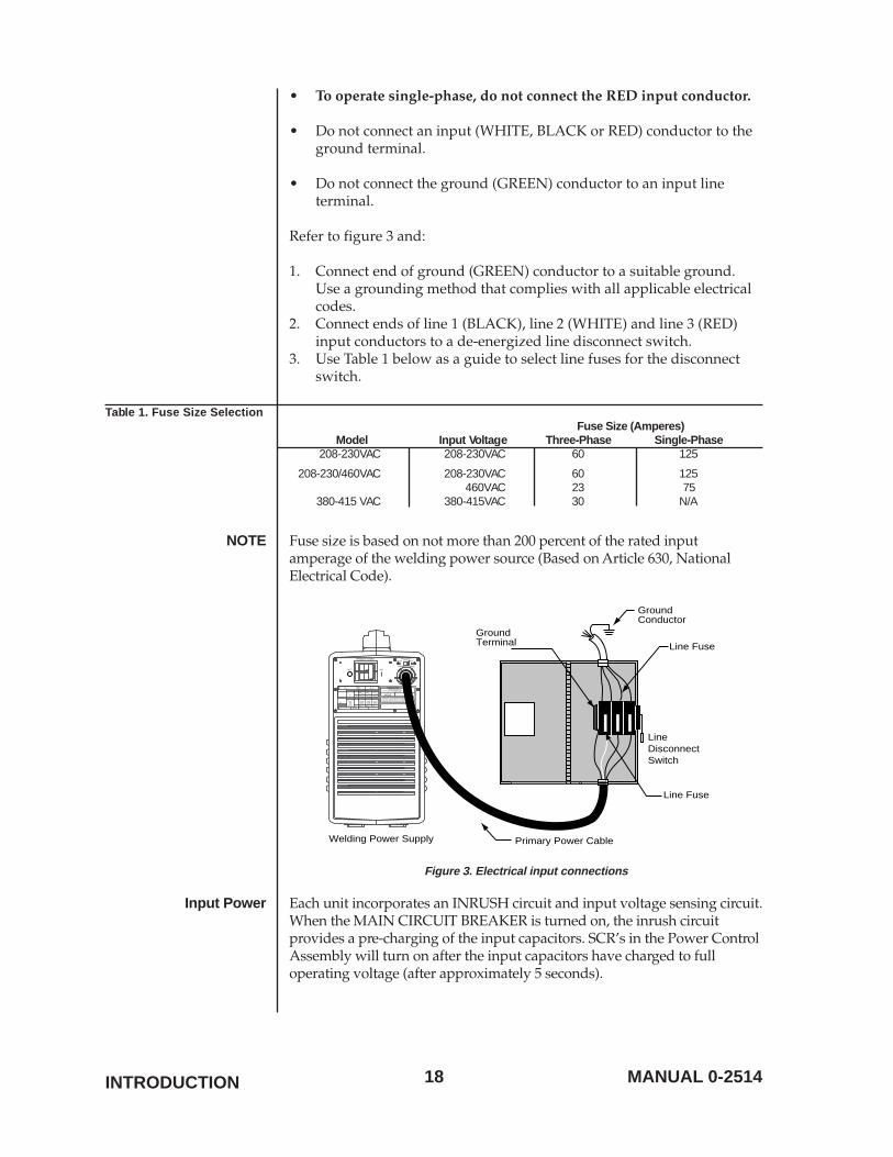
• To operate single-phase, do not connect the RED input conductor.
• Do not connect an input (WHITE, BLACK or RED) conductor to theground terminal.
• Do not connect the ground (GREEN) conductor to an input lineterminal.
Refer to figure 3 and:
1. Connect end of ground (GREEN) conductor to a suitable ground.Use a grounding method that complies with all applicable electricalcodes.
2. Connect ends of line 1 (BLACK), line 2 (WHITE) and line 3 (RED)input conductors to a de-energized line disconnect switch.
3. Use Table 1 below as a guide to select line fuses for the disconnectswitch.
Table 1. Fuse Size SelectionFuse Size (Amperes)
Model Input Voltage Three-Phase Single-Phase208-230VAC 208-230VAC 60 125
208-230/460VAC 208-230VAC 60 125460VAC 23 75
380-415 VAC 380-415VAC 30 N/A
NOTE Fuse size is based on not more than 200 percent of the rated inputamperage of the welding power source (Based on Article 630, NationalElectrical Code).
THERMADYNE
OFF ON
208-230V 460V
INPUT SELECTSWITCHPRIMARY POWER
PRIMARY CABLE
TURN OFF YOUR MAIN POWER SOURCE ANDCIRCUIT BREAKER OF THIS WELDER BEFOREMAINTENANCE OR INSPECTION
5A/10V - 400A/36V
400/ 300/ 230/ 60% 25% 100%
280A 210A 160A
U
S
U V
U V
X
I
31V36/ 32/ 28/
28V 26V
64
208V3/1
3/1
230V460V
60/80 Hz
61/78A 40/63A66/70A 37/48A27/36A 18/24A
28/37A26/34A13/17A
21.9/16.2kVA
14.6/10.9kVA
10/8.0kVA
IP 23S
f1f2 IEC974
2
2
1
0
1
400S
Thermal DynamicsWEST LEBANON, NEW HAMPSHIRE USA 03784
MADE IN JAPAN
Primary Power Cable
Line Fuse
Line Fuse
LineDisconnectSwitch
Welding Power Supply
GroundConductor
GroundTerminal
Figure 3. Electrical input connections
Input Power Each unit incorporates an INRUSH circuit and input voltage sensing circuit.When the MAIN CIRCUIT BREAKER is turned on, the inrush circuitprovides a pre-charging of the input capacitors. SCR’s in the Power ControlAssembly will turn on after the input capacitors have charged to fulloperating voltage (after approximately 5 seconds).
INTRODUCTION
19MANUAL 0-2514
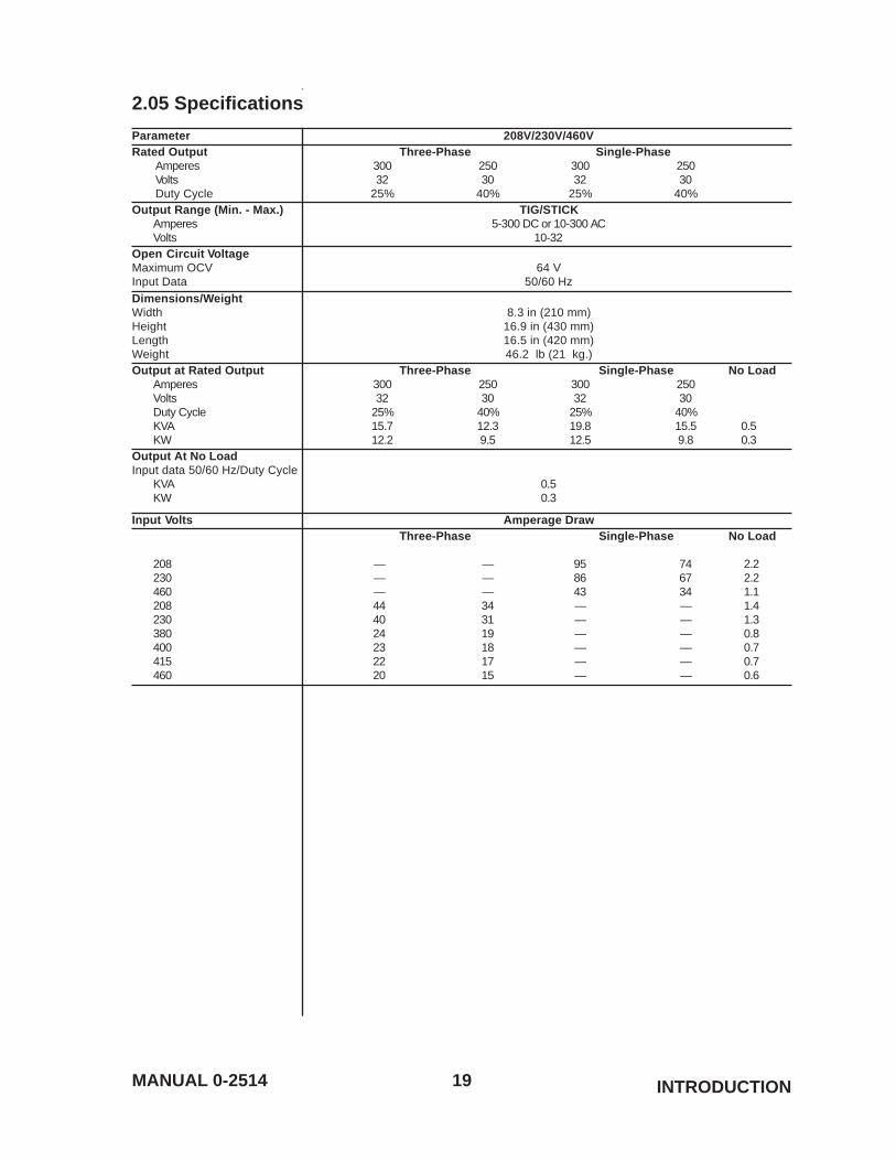
2.05 Specifications
Parameter 208V/230V/460VRated Output Three-Phase Single-Phase
Amperes 300 250 300 250Volts 32 30 32 30Duty Cycle 25% 40% 25% 40%
Output Range (Min. - Max.) TIG/STICKAmperes 5-300 DC or 10-300 ACVolts 10-32
Open Circuit VoltageMaximum OCV 64 VInput Data 50/60 HzDimensions/WeightWidth 8.3 in (210 mm)Height 16.9 in (430 mm)Length 16.5 in (420 mm)Weight 46.2 lb (21 kg.)Output at Rated Output Three-Phase Single-Phase No Load
Amperes 300 250 300 250Volts 32 30 32 30Duty Cycle 25% 40% 25% 40%KVA 15.7 12.3 19.8 15.5 0.5KW 12.2 9.5 12.5 9.8 0.3
Output At No LoadInput data 50/60 Hz/Duty Cycle
KVA 0.5KW 0.3
Input Volts Amperage DrawThree-Phase Single-Phase No Load
208 — — 95 74 2.2230 — — 86 67 2.2460 — — 43 34 1.1208 44 34 — — 1.4230 40 31 — — 1.3380 24 19 — — 0.8400 23 18 — — 0.7415 22 17 — — 0.7460 20 15 — — 0.6
INTRODUCTION
20 MANUAL 0-2514
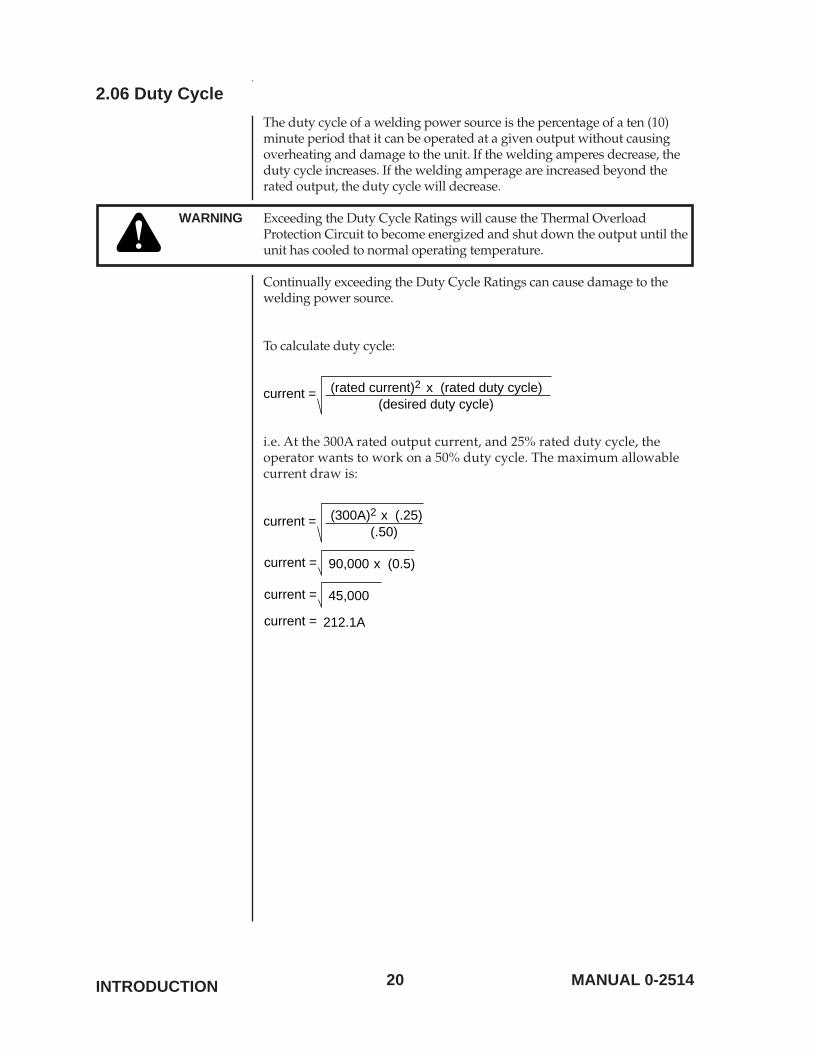
2.06 Duty Cycle
The duty cycle of a welding power source is the percentage of a ten (10)minute period that it can be operated at a given output without causingoverheating and damage to the unit. If the welding amperes decrease, theduty cycle increases. If the welding amperage are increased beyond therated output, the duty cycle will decrease.
WARNING Exceeding the Duty Cycle Ratings will cause the Thermal OverloadProtection Circuit to become energized and shut down the output until theunit has cooled to normal operating temperature.
Continually exceeding the Duty Cycle Ratings can cause damage to thewelding power source.
To calculate duty cycle:
(rated current)2 x (rated duty cycle)(desired duty cycle)
current =
i.e. At the 300A rated output current, and 25% rated duty cycle, theoperator wants to work on a 50% duty cycle. The maximum allowablecurrent draw is:
(300A)2 x (.25)(.50)
current =
90,000 x (0.5)current =
45,000 current =
212.1A current =
INTRODUCTION
21MANUAL 0-2514 OPERATOR CONTROLS
3.0 OPERATOR CONTROLS
3.01 Front and Rear panel operator controls
14 8 4 10 11
17
2
1
12
13
3
5
6
7
15
18
16
9
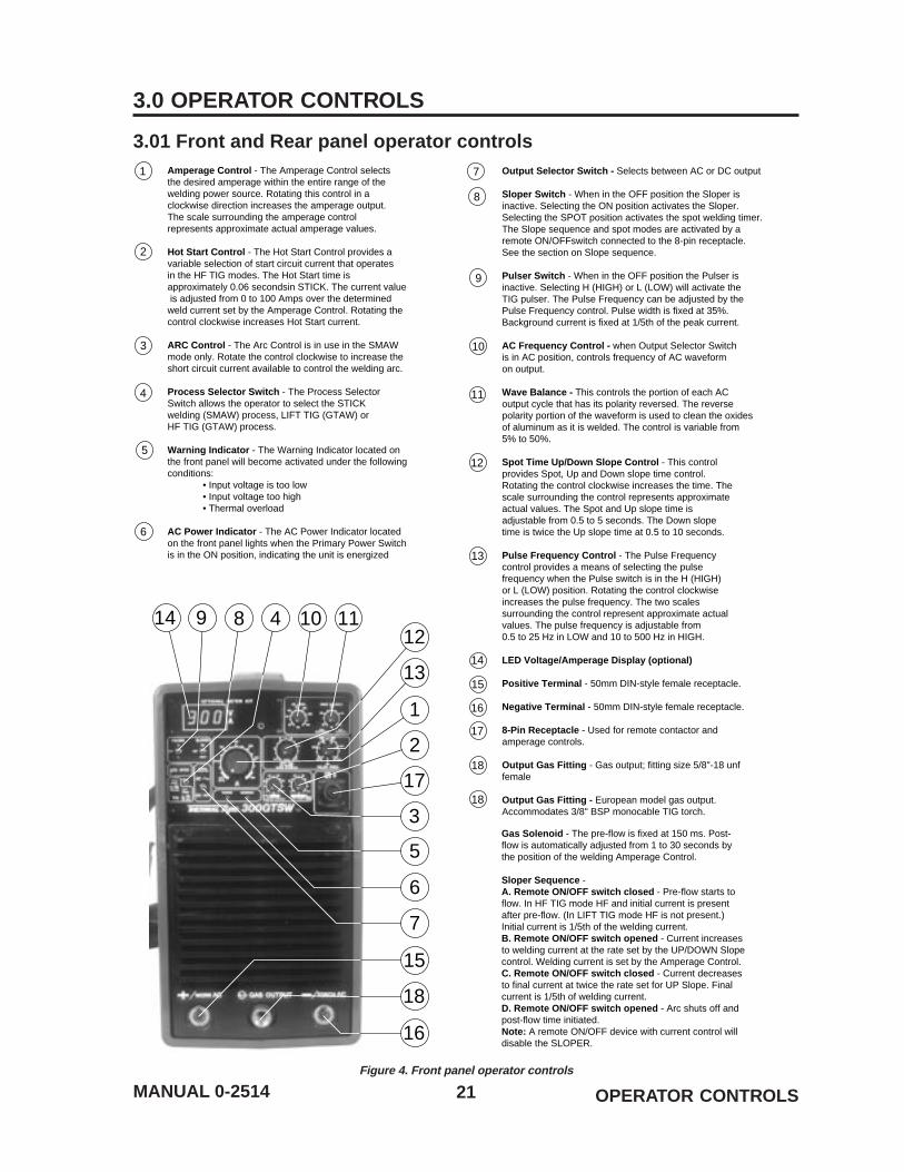
1 Amperage Control - The Amperage Control selectsthe desired amperage within the entire range of thewelding power source. Rotating this control in a clockwise direction increases the amperage output. The scale surrounding the amperage control represents approximate actual amperage values.
Hot Start Control - The Hot Start Control provides a variable selection of start circuit current that operates in the HF TIG modes. The Hot Start time isapproximately 0.06 secondsin STICK. The current value is adjusted from 0 to 100 Amps over the determined weld current set by the Amperage Control. Rotating the control clockwise increases Hot Start current.
ARC Control - The Arc Control is in use in the SMAW mode only. Rotate the control clockwise to increase the short circuit current available to control the welding arc.
Process Selector Switch - The Process SelectorSwitch allows the operator to select the STICKwelding (SMAW) process, LIFT TIG (GTAW) orHF TIG (GTAW) process.
Warning Indicator - The Warning Indicator located onthe front panel will become activated under the followingconditions:
• Input voltage is too low• Input voltage too high• Thermal overload
AC Power Indicator - The AC Power Indicator locatedon the front panel lights when the Primary Power Switchis in the ON position, indicating the unit is energized
2
3
4
5
6
7 Output Selector Switch - Selects between AC or DC output
Sloper Switch - When in the OFF position the Sloper is inactive. Selecting the ON position activates the Sloper. Selecting the SPOT position activates the spot welding timer. The Slope sequence and spot modes are activated by a remote ON/OFFswitch connected to the 8-pin receptacle. See the section on Slope sequence.
Pulser Switch - When in the OFF position the Pulser isinactive. Selecting H (HIGH) or L (LOW) will activate the TIG pulser. The Pulse Frequency can be adjusted by the Pulse Frequency control. Pulse width is fixed at 35%. Background current is fixed at 1/5th of the peak current.
AC Frequency Control - when Output Selector Switch is in AC position, controls frequency of AC waveform on output.
Wave Balance - This controls the portion of each AC output cycle that has its polarity reversed. The reverse polarity portion of the waveform is used to clean the oxides of aluminum as it is welded. The control is variable from 5% to 50%.
Spot Time Up/Down Slope Control - This controlprovides Spot, Up and Down slope time control.Rotating the control clockwise increases the time. Thescale surrounding the control represents approximateactual values. The Spot and Up slope time isadjustable from 0.5 to 5 seconds. The Down slopetime is twice the Up slope time at 0.5 to 10 seconds.
Pulse Frequency Control - The Pulse Frequency control provides a means of selecting the pulse frequency when the Pulse switch is in the H (HIGH)or L (LOW) position. Rotating the control clockwise increases the pulse frequency. The two scales surrounding the control represent approximate actual values. The pulse frequency is adjustable from0.5 to 25 Hz in LOW and 10 to 500 Hz in HIGH.
LED Voltage/Amperage Display (optional)
Positive Terminal - 50mm DIN-style female receptacle.
Negative Terminal - 50mm DIN-style female receptacle.
8-Pin Receptacle - Used for remote contactor andamperage controls.
Output Gas Fitting - Gas output; fitting size 5/8"-18 unffemale
Output Gas Fitting - European model gas output. Accommodates 3/8" BSP monocable TIG torch.
8
9
10
12
13
18
18
16
17
Gas Solenoid - The pre-flow is fixed at 150 ms. Post-flow is automatically adjusted from 1 to 30 seconds bythe position of the welding Amperage Control.
Sloper Sequence - A. Remote ON/OFF switch closed - Pre-flow starts toflow. In HF TIG mode HF and initial current is present after pre-flow. (In LIFT TIG mode HF is not present.)Initial current is 1/5th of the welding current.B. Remote ON/OFF switch opened - Current increasesto welding current at the rate set by the UP/DOWN Slopecontrol. Welding current is set by the Amperage Control.C. Remote ON/OFF switch closed - Current decreasesto final current at twice the rate set for UP Slope. Finalcurrent is 1/5th of welding current.D. Remote ON/OFF switch opened - Arc shuts off andpost-flow time initiated.Note: A remote ON/OFF device with current control will disable the SLOPER.
14
15
11
Figure 4. Front panel operator controls
22 MANUAL 0-2514OPERATOR CONTROLS
19
21
22
20
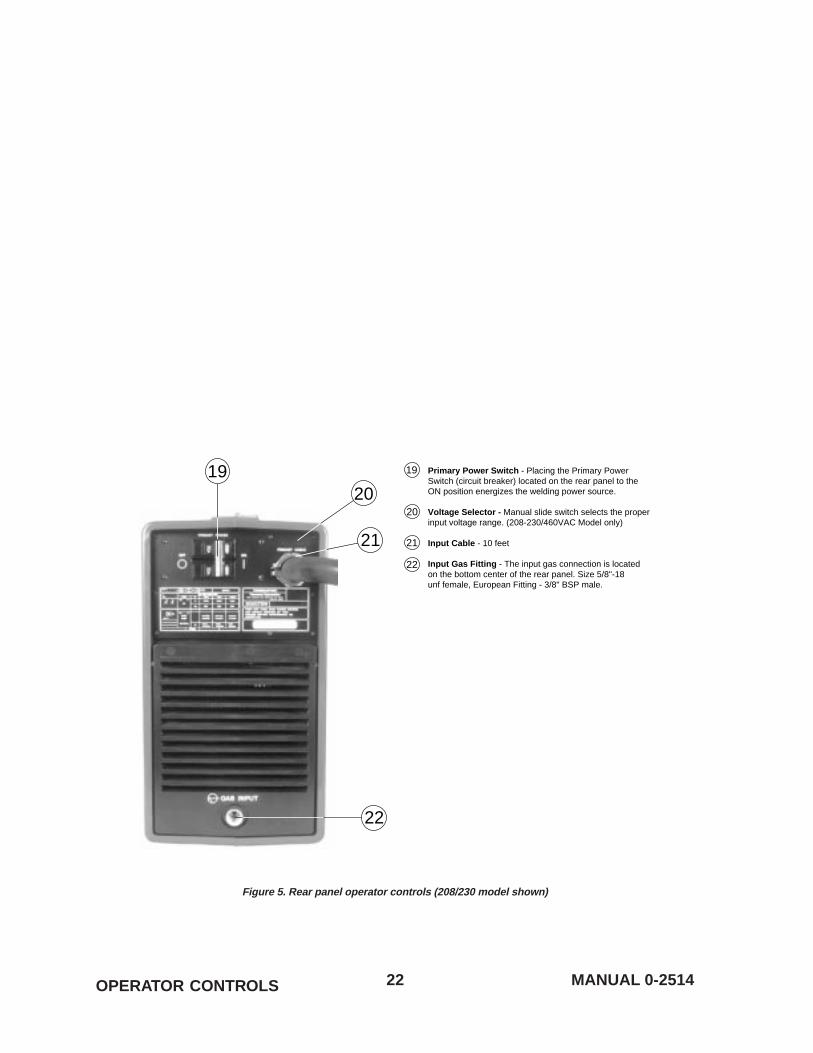
Primary Power Switch - Placing the Primary Power Switch (circuit breaker) located on the rear panel to the ON position energizes the welding power source.
Voltage Selector - Manual slide switch selects the proper input voltage range. (208-230/460VAC Model only)
Input Cable - 10 feet
Input Gas Fitting - The input gas connection is locatedon the bottom center of the rear panel. Size 5/8"-18unf female, European Fitting - 3/8" BSP male.
20
21
22
19
Figure 5. Rear panel operator controls (208/230 model shown)

23MANUAL 0-2514
3.02 Setup for Operation
Arc Control The ARC CONTROL provides a variable selection of short circuitamperage to suit individual welding situations when operating in theSTICK welding (SMAW) mode.
5 - 300A
75%0
145A
Main Knob Arc Control
100%25% 50%
19V 10V/100A Droop
Arc Control KnobMain Knob = Arc Control Knob
= Less Than 310 Output Current Limit
Figure 6. Arc Control Characteristics
SETUP FOR OPERATION
24 MANUAL 0-2514
3.02 Setup for Operation
Shielded Metal Arc Welding (SMAW) DC or AC Operation
WARNING Read and follow all safety precautions on pages iii-v of this manual beforepreceding with operation.
1. Install and connect unit according to the installation instructions insection 2.04, page 17, of this manual.
2. Wear dry insulating gloves and clothing.
For DC Operation
3. Connect the ground cable (work clamp) to clean, bare metal onworkpiece. For the majority of electrodes in use, the work clamp isconnected to the NEGATIVE (-) output terminal.
4. Select proper electrode.
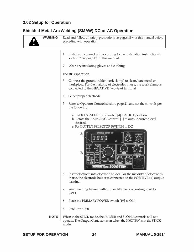
5. Refer to Operator Control section, page 21, and set the controls perthe following:
a. PROCESS SELECTOR switch [4] to STICK position.b. Rotate the AMPERAGE control [1] to output current level
desired.c. Set OUTPUT SELECTOR SWITCH to DC.
4
1
6. Insert electrode into electrode holder. For the majority of electrodesin use, the electrode holder is connected to the POSITIVE (+) outputterminal.
7. Wear welding helmet with proper filter lens according to ANSIZ49.1.
8. Place the PRIMARY POWER switch [19] to ON.
9. Begin welding.
NOTE When in the STICK mode, the PULSER and SLOPER controls will notoperate. The Output Contactor is on when the 300GTSW is in the STICKmode.
SETUP FOR OPERATION
25MANUAL 0-2514
For AC Operation
3. Connect the ground cable (work clamp) to clean, bare metal onworkpiece. The work clamp is connected to the POSITIVE (+) outputterminal.
4. Select proper electrode.
5. Refer to Operator Control section, page 21, and set the controls perthe following:
a. PROCESS SELECTOR switch [4] to STICK position.b. Rotate the AMPERAGE control [1] to output current level
desired.c. Set OUTPUT SELECTOR SWITCH to AC.d. Adjust AC FREQUENCY CONTROL to suit welding conditions;
usually set at MAXIMUM.e. Adjust WAVE BALANCE Control to suit welding conditions;
usually set at MAXIMUM.f. Adjust HOT START to suit welding conditions.
6. Insert electrode into electrode holder. The electrode holder isconnected to the NEGATIVE (-) output terminal.
7. Wear welding helmet with proper filter lens according to ANSIZ49.1.
8. Place the PRIMARY POWER switch [19] to ON.
9. Begin welding.
NOTE When in the STICK mode, the PULSER and SLOPER controls will notoperate. The Output Contactor is on when the 300GTSW is in the STICKmode.
SETUP FOR OPERATION
26 MANUAL 0-2514
3.02 Setup for Operation
Gas Tungsten Arc Welding (GTAW) High Frequency/Lift Start
WARNING Read and follow all safety precautions on pages 2-5 of this manual beforepreceding with operation.
1. Install and connect unit according to the installation instructions insection 2.04, page 17, of this manual.
2. Select proper tungsten electrode (refer to Electrode Selection Table 2,page 30).
3. Prepare tungsten electrode and insert into torch, the TIG TORCH isconnected to the NEGATIVE (-) output terminal.
4. Wear dry insulating gloves and clothing.
5. Connect shielding gas supply to gas fitting on back panel.
6. Connect TIG torch gas fitting to output 3/8" BSP or 5/8"-18 UNFfitting where applicable.
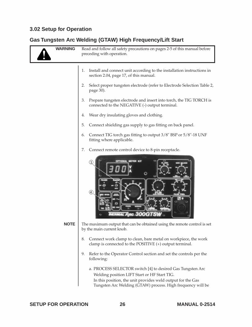
7. Connect remote control device to 8-pin receptacle.
4
1
NOTE The maximum output that can be obtained using the remote control is setby the main current knob.
8. Connect work clamp to clean, bare metal on workpiece, the workclamp is connected to the POSITIVE (+) output terminal.
9. Refer to the Operator Control section and set the controls per thefollowing:
a. PROCESS SELECTOR switch [4] to desired Gas Tungsten ArcWelding position LIFT Start or HF Start TIG.In this position, the unit provides weld output for the GasTungsten Arc Welding (GTAW) process. High frequency will be
SETUP FOR OPERATION
27MANUAL 0-2514
present from the time the contactor is closed until a welding arc isestablished. Once an arc is established, high frequency is no longerpresent. High frequency is present any time the arc is broken toaid in restarting the arc as long as the contactor is energized.When the PROCESS SELECTOR switch is in this position, theARC CONTROL will not function but the HOT START will.
NOTE If using HOT START in GTAW mode: Set below Maximum current capacityof electrode (Table 2, page 30).
In this mode, the unit provides weld output for the Gas TungstenArc Welding (GTAW) process. High frequency will not be present.When the PROCESS SELECTOR switch is in this position, theHOT START ARC CONTROL will not function. The unit willprovide a low open circuit voltage and approximately 15 amps tothe tungsten electrode when touched to the work. After theTungsten Electrode is lifted away and the welding arc becomesestablished, the output current will be regulated at the currentlevel determined by the AMPERAGE control [1].
b. Rotate the AMPERAGE control [1] to output current level desired.
c. Set AC/DC switch to desired welding output.
NOTE In AC mode connect the TIG torch to the negative output receptacle. *Ifmonocable TIG torch is used connect to 3/8" BSP fitting.
8. Turn on shielding gas.
9. Wear welding helmet with proper filter lens according to ANSIZ49.1.
10. Place the PRIMARY POWER switch [19] to ON.
11. Activate remote control device.NOTES a. In LIFT TIG mode, touch electrode to work and lift to start arc.
b. In HF TIG mode, high frequency will start, followed by welding arc.
12. Begin welding.
WARNING HIGH CONCENTRATION OF SHIELDING GAS can impair health or kill.Shut off gas supply when not in use.
SETUP FOR OPERATION
HF START(GTAW with HighFrequency Start)
LIFT START(GTAW without
High Frequency)
28 MANUAL 0-2514
3.01 Setup for Operation
Gas Tungsten Arc Welding-Pulsed (GTAW-P) -Sloped (GTAW-S) -TIG Spot
WARNING Read and follow all safety precautions on pages 2-5 of this manual beforepreceding with operation.
1. Install and connect unit according to the installation instructions insection 2.04, page 17, of this manual.
2. Select proper tungsten electrode (refer to Electrode Selection Table 2,page 30).
3. Prepare tungsten electrode and insert into torch, connect to theNEGATIVE (-) output terminal.
4. Wear dry insulating gloves and clothing.
5. Connect shielding gas supply to gas fitting on back panel.
6. Connect TIG torch gas fitting to output 3/8" BSP or 5/8"-18 UNFfitting where applicable.
7 Connect remote control device to 8-pin receptacle.
8. Connect work clamp to clean, bare metal on workpiece, the workclamp is connected to the POSITIVE (+) output terminal.
9. PROCESS SELECTOR switch [4] to desired gas tungsten arc weldingposition. LIFT or HF TIG.a. Set AC/DC switch to desired welding output.
10. Refer to the Operator Control section, page 21, and set the controls per thefollowing:
NOTE In AC mode connect the TIG torch to the negative output receptacle. *Ifmonocable TIG torch is used connect to 3/8" BSP fitting.
A. PULSE TIG welding1. Set PULSER SELECTOR switch [9] to desired frequency pulse
of high or low.2. Rotate the AMPERAGE control [1] to desired output current
level.3. Rotate PULSE FREQUENCY control [13] to desired frequency
position.B. SLOPE TIG welding
1. Set SLOPER switch [8] to SLOPE position.2. Rotate AMPERAGE control [1] to desire welding current level.3. Rotate SPOT TIME UP/DOWN SLOPE control [12] to desired
UP/DOWN slope time.NOTE Only use a remote ON/OFF switch to control SLOPE sequence. See the
Operator Control section on page 21.
SETUP FOR OPERATION
29MANUAL 0-2514
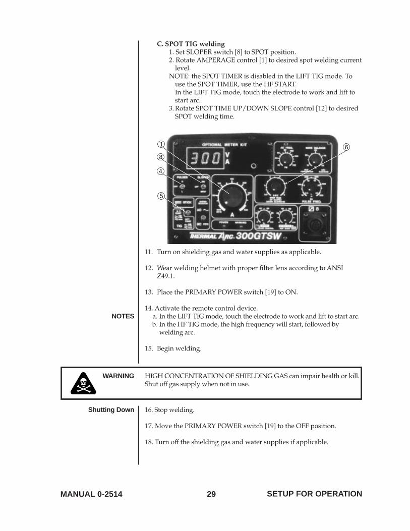
C. SPOT TIG welding1. Set SLOPER switch [8] to SPOT position.2. Rotate AMPERAGE control [1] to desired spot welding current
level.NOTE: the SPOT TIMER is disabled in the LIFT TIG mode. To
use the SPOT TIMER, use the HF START.In the LIFT TIG mode, touch the electrode to work and lift tostart arc.
3. Rotate SPOT TIME UP/DOWN SLOPE control [12] to desiredSPOT welding time.
5
1 6
8
4
11. Turn on shielding gas and water supplies as applicable.
12. Wear welding helmet with proper filter lens according to ANSIZ49.1.
13. Place the PRIMARY POWER switch [19] to ON.
14. Activate the remote control device.NOTES a. In the LIFT TIG mode, touch the electrode to work and lift to start arc.
b. In the HF TIG mode, the high frequency will start, followed bywelding arc.
15. Begin welding.
WARNING HIGH CONCENTRATION OF SHIELDING GAS can impair health or kill.Shut off gas supply when not in use.
Shutting Down 16. Stop welding.
17. Move the PRIMARY POWER switch [19] to the OFF position.
18. Turn off the shielding gas and water supplies if applicable.
SETUP FOR OPERATION
30 MANUAL 0-2514
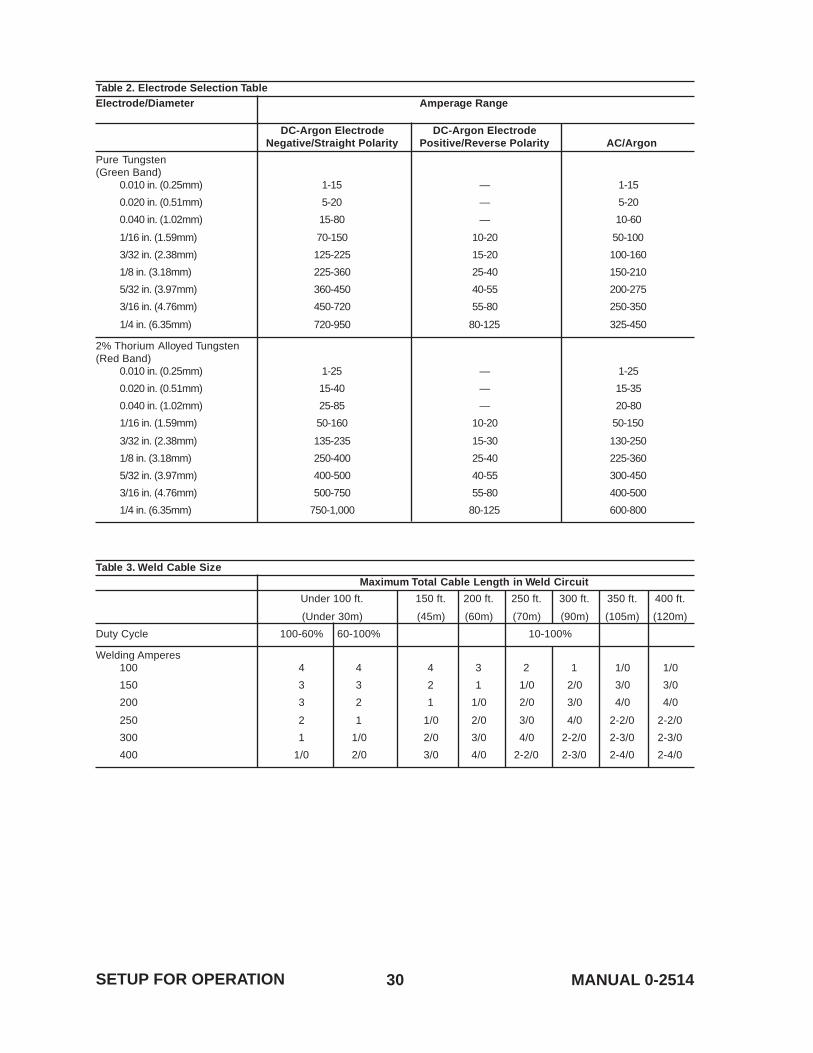
Table 2. Electrode Selection TableElectrode/Diameter Amperage Range
DC-Argon Electrode DC-Argon ElectrodeNegative/Straight Polarity Positive/Reverse Polarity AC/Argon
Pure Tungsten(Green Band)
0.010 in. (0.25mm) 1-15 — 1-15
0.020 in. (0.51mm) 5-20 — 5-20
0.040 in. (1.02mm) 15-80 — 10-60
1/16 in. (1.59mm) 70-150 10-20 50-100
3/32 in. (2.38mm) 125-225 15-20 100-160
1/8 in. (3.18mm) 225-360 25-40 150-210
5/32 in. (3.97mm) 360-450 40-55 200-275
3/16 in. (4.76mm) 450-720 55-80 250-350
1/4 in. (6.35mm) 720-950 80-125 325-450
2% Thorium Alloyed Tungsten(Red Band)
0.010 in. (0.25mm) 1-25 — 1-25
0.020 in. (0.51mm) 15-40 — 15-35
0.040 in. (1.02mm) 25-85 — 20-80
1/16 in. (1.59mm) 50-160 10-20 50-150
3/32 in. (2.38mm) 135-235 15-30 130-250
1/8 in. (3.18mm) 250-400 25-40 225-360
5/32 in. (3.97mm) 400-500 40-55 300-450
3/16 in. (4.76mm) 500-750 55-80 400-500
1/4 in. (6.35mm) 750-1,000 80-125 600-800
Table 3. Weld Cable SizeMaximum Total Cable Length in Weld Circuit
Under 100 ft. 150 ft. 200 ft. 250 ft. 300 ft. 350 ft. 400 ft.
(Under 30m) (45m) (60m) (70m) (90m) (105m) (120m)
Duty Cycle 100-60% 60-100% 10-100%
Welding Amperes100 4 4 4 3 2 1 1/0 1/0
150 3 3 2 1 1/0 2/0 3/0 3/0
200 3 2 1 1/0 2/0 3/0 4/0 4/0
250 2 1 1/0 2/0 3/0 4/0 2-2/0 2-2/0
300 1 1/0 2/0 3/0 4/0 2-2/0 2-3/0 2-3/0
400 1/0 2/0 3/0 4/0 2-2/0 2-3/0 2-4/0 2-4/0
SETUP FOR OPERATION
31MANUAL 0-2514 BASIC TROUBLESHOOTING
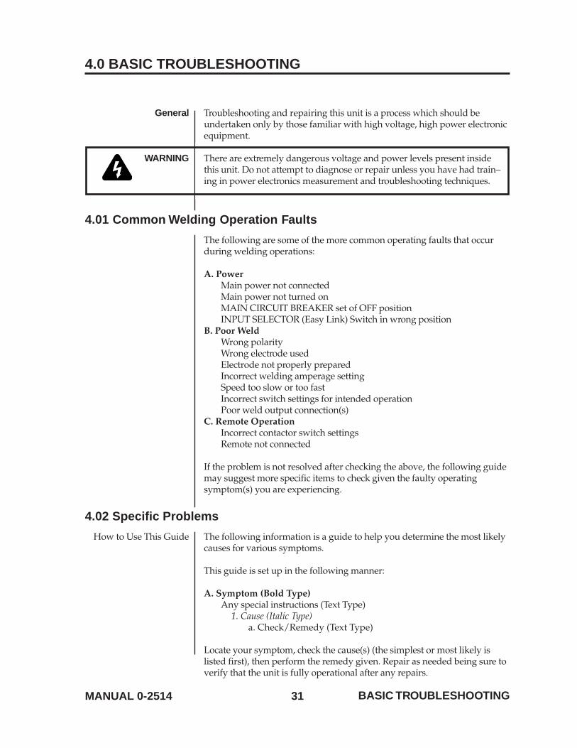
4.0 BASIC TROUBLESHOOTING
General Troubleshooting and repairing this unit is a process which should beundertaken only by those familiar with high voltage, high power electronicequipment.
WARNING There are extremely dangerous voltage and power levels present insidethis unit. Do not attempt to diagnose or repair unless you have had train–ing in power electronics measurement and troubleshooting techniques.
4.01 Common Welding Operation Faults
The following are some of the more common operating faults that occurduring welding operations:
A. PowerMain power not connectedMain power not turned onMAIN CIRCUIT BREAKER set of OFF positionINPUT SELECTOR (Easy Link) Switch in wrong position
B. Poor WeldWrong polarityWrong electrode usedElectrode not properly preparedIncorrect welding amperage settingSpeed too slow or too fastIncorrect switch settings for intended operationPoor weld output connection(s)
C. Remote OperationIncorrect contactor switch settingsRemote not connected
If the problem is not resolved after checking the above, the following guidemay suggest more specific items to check given the faulty operatingsymptom(s) you are experiencing.
4.02 Specific Problems
How to Use This Guide The following information is a guide to help you determine the most likelycauses for various symptoms.
This guide is set up in the following manner:
A. Symptom (Bold Type)Any special instructions (Text Type)
1. Cause (Italic Type)a. Check/Remedy (Text Type)
Locate your symptom, check the cause(s) (the simplest or most likely islisted first), then perform the remedy given. Repair as needed being sure toverify that the unit is fully operational after any repairs.
32 MANUAL 0-2514BASIC TROUBLESHOOTING
A. No Weld Output; Unit is Completely Inoperative1. Line disconnect switch is in OFF position
a. Place line disconnect switch in ON position.2. Line fuse(s) open
a. Check and replace line fuse(s).3. Improper electrical input connections
a. See Section 2.04 Electrical Input Requirements, page 17, forproper input connections.
4. MAIN CIRCUIT BREAKER in OFF positiona. Check and reset MAIN CIRCUIT BREAKER if necessary.
5. INPUT SELECTOR (Easy Link) switch is set to incorrect position forapplied input voltage, 208/230/460 model only
a. Verify primary source voltage and set INPUT SELECTswitch to correct setting.
B. WARNING Indicator is ON1. Unit is in thermal shutdown mode
a. Allow cooling period of approximately five (5) minutes withthe power ON. Duty cycle should be reviewed. To reset theWARNING indicator, the power supply must be turnedOFF, then ON again.
2. Input voltage is lowa. Measure input voltage and verify that it matches the INPUT
SELECTOR (Easy Link) switch setting. The length of theinput power cable must be considered, as there will be aconsiderable voltage drop along its length.
3. Irratic input voltage – spikes over tolerance will cause the warninglight to come on for protection
a. Turn MCB off then on to reset the warning light.
C. Erratic or Improper Weld Output1. Loose welding cable connections
a. Tighten all welding cable connections.2. Incorrect welding cable size
a. Use proper size and type of cable (see Table 2, page 29).3. Improper input connections
a. Refer to Section 2.04 Electrical Input Requirements, page 17.4. Poor electrode condition
a. Replace electrode.5. If in GTAW mode, check the condition of the tungsten electrode
a. Use the recommended 2% Thoriated tungsten.6. In GTAW mode, incorrect argon gas flow
a. Verify that argon gas flow is correct; approximately12 SCFH.
7. Incorrectly set PROCESS SELECTOR switcha. Verify the PROCESS SELECTOR switch is set to match the
type of welding process being conducted.8. Wrong welding polarity
a. Verify output torch connections.
33MANUAL 0-2514 BASIC TROUBLESHOOTING
D. Wandering Arc, Poor Control of Arc Direction1. Wrong size tungsten electrode, typically larger than recommended
a. Use proper size electrode for amperage selected (see Table 2,page 29).
2. Improperly prepared tungsten electrodea. Prepare tungsten properly.
3. Gas Flow rate too higha. Reduce flow rate to approximately 12 SCFH.
4. Drafts blowing shielding gas away from tungsten electrodea. Shield weld zone from drafts and check condition of
tungsten electrode.5. Loose gas fitting on regulator or gas line drawing air into weld zone,
causing green/blue discoloration of workpiecea. Check and tighten all gas fittings.
6. Water in torcha. Refer to torch parts list for part(s) requiring replacement
and repair torch as necessary.
E. No High Frequency at Torch When PROCESS SELECTOR Switch isin HF TIG Position
1. PROCESS SELECTOR switch is not in the HF TIG positiona. Place switch in HF TIG position.
2. Drafts blowing shielding gas away from tungsten electrodea. Shield weld zone from drafts and check condition of
tungsten electrode.3. Loose gas fitting on regulator or gas line drawing air into weld zone
a. Check and tighten all gas fittings.4. Water in torch
a. Refer to torch parts list for part(s) requiring replacementand repair torch as necessary.
5. Tungsten condition is poora. Replace electrode.
6. Electrode too high off metala. Reduce stand-off.
7. Faulty TIG Torcha. Replace TIG torch.
8. Work lead not connecteda. Verify all connections to torch and workpiece.
F. Lack of High Frequency; Difficulty in Establishing an Arc1. Dissipation of high frequency from torch cable or conductive gas hose
a. Be sure that the torch cable is not near any grounded metal.Do not use conductive gas hose.
2. Weld cable leakagea. Check cables and torch for cracked or deteriorated
insulation or bad connections. Repair or replace necessaryparts.
3. Poor ground connection to power supplya. Verify ground by trying to strike arc within one inch
(2.54cm) of ground clamp.

34 MANUAL 0-2514BASIC TROUBLESHOOTING
G. Wall Fuse/Circuit Breaker Trips When Turned ON1. Input voltage over rated limit
a. Connect to proper line voltage.
H. Green AC POWER Indicator OFF; Fan Not Operating1. Input line disconnect switch in OFF position
a. Place input line disconnect switch to ON position.2. Power supply MAIN CIRCUIT BREAKER (MCB) in OFF position
a. Place MCB to ON position.3. Input line breaker tripped/fuses blown
a. Reset MCB; check primary supply breaker or fuses andreplace if necessary. Refer to letter G above.
NOTE Verify that for single-phase operation, the RED input line is not connected.4. Open conductor in input power line
a. Check continuity and replace if necessary.
I. Red WARNING Indicator ON; No Weld Output1. Input voltage fluctuation causing protection circuits to activate
a. Monitor input power for spikes and high voltageconditions. Most power utilities will monitor and verifyline voltage.
2. Thermal sensor TH1 open (thermal shutdown)a. Allow the unit to cool for five minutes before turning the
power supply ON.
J. No Weld or Output; Fan Operating; WARNING Indicator OFF1. Faulty Remote Control Device
a. Connect a jumper between pins 2 and 3 of the REMOTE 8receptacle for contactor closure. If amperage and voltagecan be adjusted with front panel controls, repair or replaceremote control device.
K. Low or Maximum Weld Output With No Control1. Faulty remote control device
a. Connect a jumper between pins 2 and 3 of the REMOTE 8receptacle for contactor closure. If amperage and voltagecan be adjusted with front panel controls, repair or replaceremote control device.
L. Limited Weld Output1. Poor primary input voltage
a. Check primary input voltageis within ±10% of nominalvoltage, i.e. 230VAC ±10%.
M. Erratic or Improper Weld Output1. Loose welding cable connections
a. Tighten all welding cable connections.2. Improper setup
a. Check for proper connection of input power.

35MANUAL 0-2514 BASIC TROUBLESHOOTING
3. Faulty Remote Devicea. Check all remote devices and repair or replace if necessary.
4. Tungsten condition is poor, causing discoloration of workpiecea. Replace electrode.
N. No Weld Output; Fan Not Operating; WARNING Indicator OFF1. Line voltage too low
a. Verify that input voltage matches setting on rear panelINPUT SELECTOR switch.
36 MANUAL 0-2514
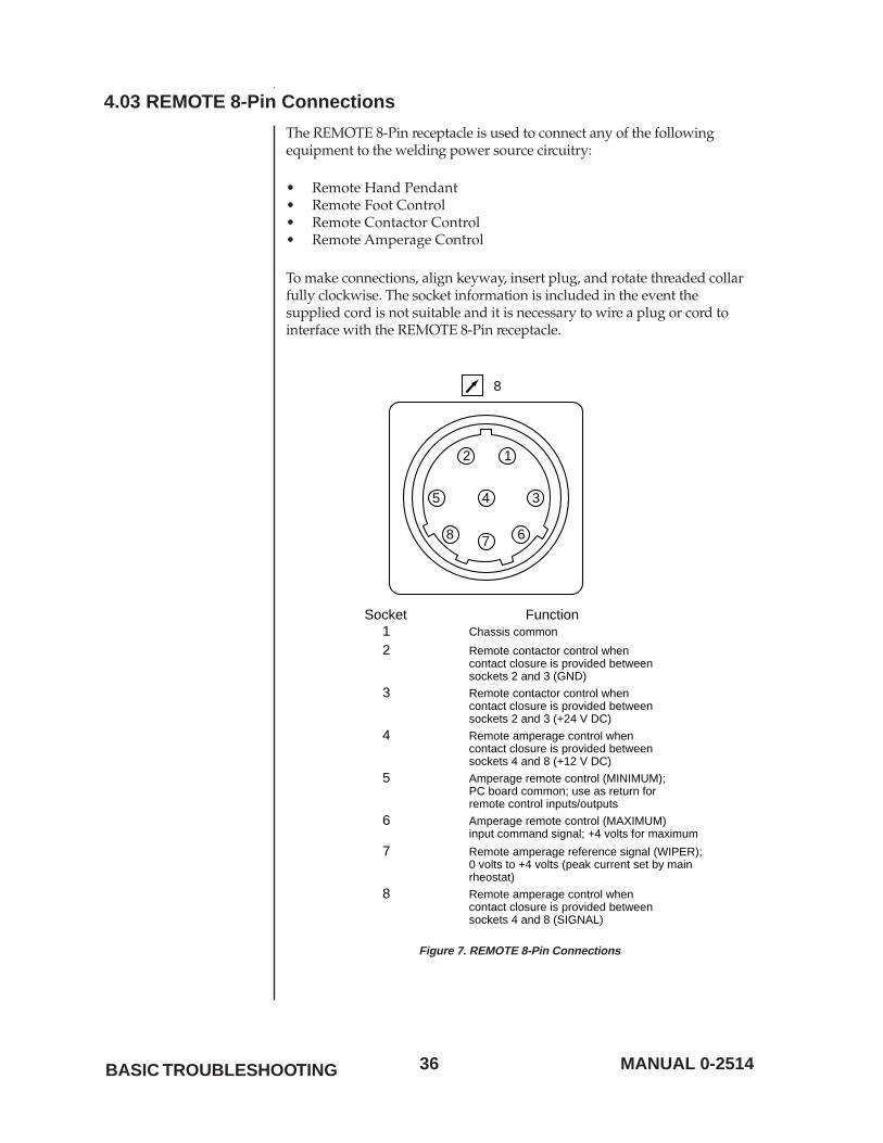
4.03 REMOTE 8-Pin Connections
The REMOTE 8-Pin receptacle is used to connect any of the followingequipment to the welding power source circuitry:
• Remote Hand Pendant• Remote Foot Control• Remote Contactor Control• Remote Amperage Control
To make connections, align keyway, insert plug, and rotate threaded collarfully clockwise. The socket information is included in the event thesupplied cord is not suitable and it is necessary to wire a plug or cord tointerface with the REMOTE 8-Pin receptacle.
2
Socket1 Chassis common
2 Remote contactor control whencontact closure is provided betweensockets 2 and 3 (GND)
Function
345
678
8
1
3 Remote contactor control whencontact closure is provided betweensockets 2 and 3 (+24 V DC)
4 Remote amperage control whencontact closure is provided betweensockets 4 and 8 (+12 V DC)
8 Remote amperage control whencontact closure is provided betweensockets 4 and 8 (SIGNAL)
5 Amperage remote control (MINIMUM);PC board common; use as return for remote control inputs/outputs
6 Amperage remote control (MAXIMUM)input command signal; +4 volts for maximum
7 Remote amperage reference signal (WIPER);0 volts to +4 volts (peak current set by mainrheostat)
Figure 7. REMOTE 8-Pin Connections
BASIC TROUBLESHOOTING

37MANUAL 0-2514
38 MANUAL 0-2514
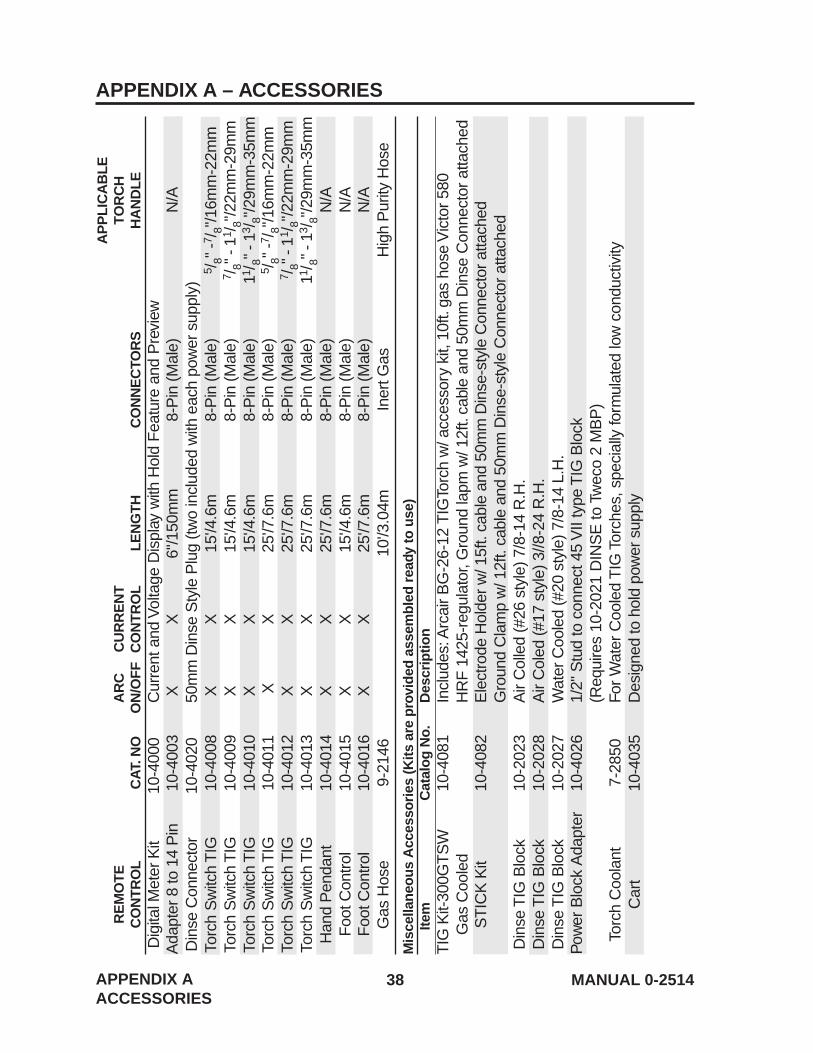
APPENDIX A – ACCESSORIESA
PP
LIC
AB
LER
EM
OTE
AR
CC
UR
RE
NT
TOR
CH
CO
NTR
OL
CAT
. NO
ON
/OFF
CO
NTR
OL
LEN
GTH
CO
NN
EC
TOR
SH
AN
DLE
Dig
ital M
eter
Kit
10-4
000
Cur
rent
and
Vol
tage
Dis
play
with
Hol
d F
eatu
re a
nd P
revi
ewA
dapt
er 8
to 1
4 P
in10
-400
3X
X6"
/150
mm
8-P
in (M
ale)
N/A
Din
se C
onne
ctor
10-4
020
50m
m D
inse
Sty
le P
lug
(two
incl
uded
with
eac
h po
wer
sup
ply)
Torc
h S
witc
h T
IG10
-400
8X
X15
'/4.6
m8-
Pin
(Mal
e)5 /
8" -
7 /8"
/16m
m-2
2mm
Torc
h S
witc
h T
IG10
-400
9X
X15
'/4.6
m8-
Pin
(Mal
e)7 /
8" -
11/ 8"
/22m
m-2
9mm
Torc
h S
witc
h T
IG10
-401
0X
X15
'/4.6
m8-
Pin
(Mal
e)11
/ 8" -
13/ 8"
/29m
m-3
5mm
Torc
h S
witc
h T
IG10
-401
1X
X25
'/7.6
m8-
Pin
(Mal
e)5 /
8" -
7 /8"
/16m
m-2
2mm
Torc
h S
witc
h T
IG10
-401
2X
X25
'/7.6
m8-
Pin
(Mal
e)7 /
8" -
11/ 8"
/22m
m-2
9mm
Torc
h S
witc
h T
IG10
-401
3X
X25
'/7.6
m8-
Pin
(Mal
e)11
/ 8" -
13/ 8"
/29m
m-3
5mm
Han
d P
enda
nt10
-401
4X
X25
'/7.6
m8-
Pin
(Mal
e)N
/AF
oot C
ontro
l10
-401
5X
X15
'/4.6
m8-
Pin
(Mal
e)N
/AF
oot C
ontro
l10
-401
6X
X25
'/7.6
m8-
Pin
(Mal
e)N
/AG
as H
ose
9-21
4610
'/3.0
4mIn
ert G
asH
igh
Pur
ity H
ose
Mis
cella
neou
s A
cces
sorie
s (K
its a
re p
rovi
ded
asse
mbl
ed re
ady
to u
se)
Item
Cat
alog
No.
Des
crip
tion
TIG
Kit-
300G
TS
W10
-408
1In
clud
es: A
rcai
r B
G-2
6-12
TIG
Torc
h w
/ acc
esso
ry k
it, 1
0ft.
gas
hose
Vic
tor
580
Gas
Coo
led
HR
F 1
425-
regu
lato
r, G
roun
d la
pm w
/ 12f
t. ca
ble
and
50m
m D
inse
Con
nect
or a
ttach
edS
TIC
K K
it10
-408
2E
lect
rode
Hol
der w
/ 15f
t. ca
ble
and
50m
m D
inse
-sty
le C
onne
ctor
atta
ched
Gro
und
Cla
mp
w/ 1
2ft.
cabl
e an
d 50
mm
Din
se-s
tyle
Con
nect
or a
ttach
edD
inse
TIG
Blo
ck10
-202
3A
ir C
olle
d (#
26 s
tyle
) 7/8
-14
R.H
.D
inse
TIG
Blo
ck10
-202
8A
ir C
oled
(#17
sty
le) 3
//8-2
4 R
.H.
Din
se T
IG B
lock
10-2
027
Wat
er C
oole
d (#
20 s
tyle
) 7/8
-14
L.H
.P
ower
Blo
ck A
dapt
er10
-402
61/
2" S
tud
to c
onne
ct 4
5 V
II ty
pe T
IG B
lock
(Req
uire
s 10
-202
1 D
INS
E to
Tw
eco
2 M
BP
)To
rch
Coo
lant
7-28
50Fo
r W
ater
Coo
led
TIG
Tor
ches
, spe
cial
ly fo
rmul
ated
low
con
duct
ivity
Car
t10
-403
5D
esig
ned
to h
old
pow
er s
uppl
y
APPENDIX AACCESSORIES
39MANUAL 0-2514
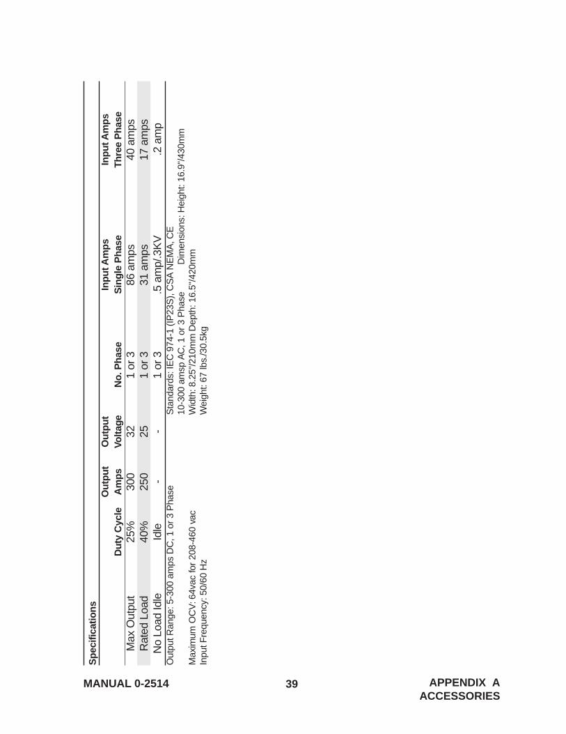
Spe
cific
atio
nsO
utpu
tO
utpu
tIn
put A
mps
Inpu
t Am
psD
uty
Cyc
leA
mps
Volta
geN
o. P
hase
Sin
gle
Pha
seTh
ree
Pha
seM
ax O
utpu
t25
%30
032
1 or
386
am
ps40
am
psR
ated
Loa
d40
%25
025
1 or
331
am
ps17
am
psN
o Lo
ad Id
leId
le-
-1
or 3
.5 a
mp/
.3K
V.2
am
pO
utpu
t Ran
ge: 5
-300
am
ps D
C, 1
or
3 P
hase
Sta
ndar
ds: I
EC
974
-1 (I
P23
S),
CS
A N
EM
A, C
E10
-300
am
sp A
C, 1
or
3 P
hase
Dim
ensi
ons:
Hei
ght:
16.9
"/43
0mm
Max
imum
OC
V: 6
4vac
for
208-
460
vac
Wid
th: 8
.25"
/210
mm
Dep
th: 1
6.5"
/420
mm
Inpu
t Fre
quen
cy: 5
0/60
Hz
Wei
ght:
67 lb
s./3
0.5k
g
APPENDIX AACCESSORIES

40 MANUAL 0-2514

41MANUAL 0-2514
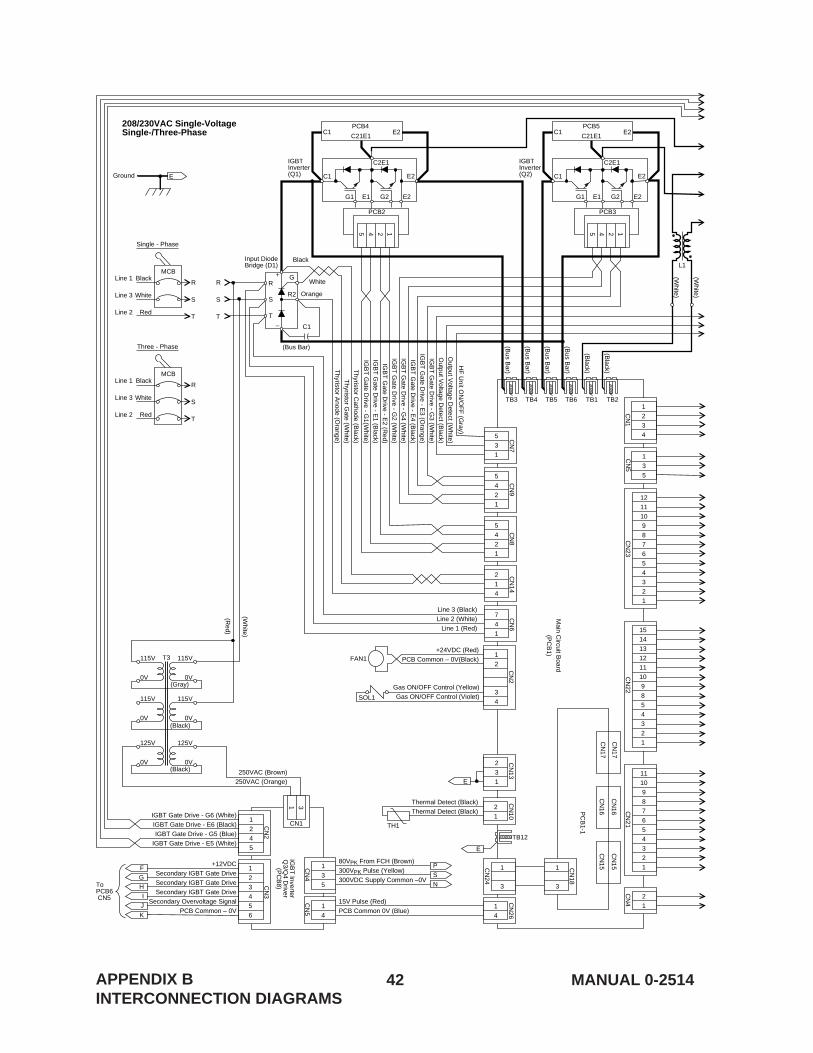
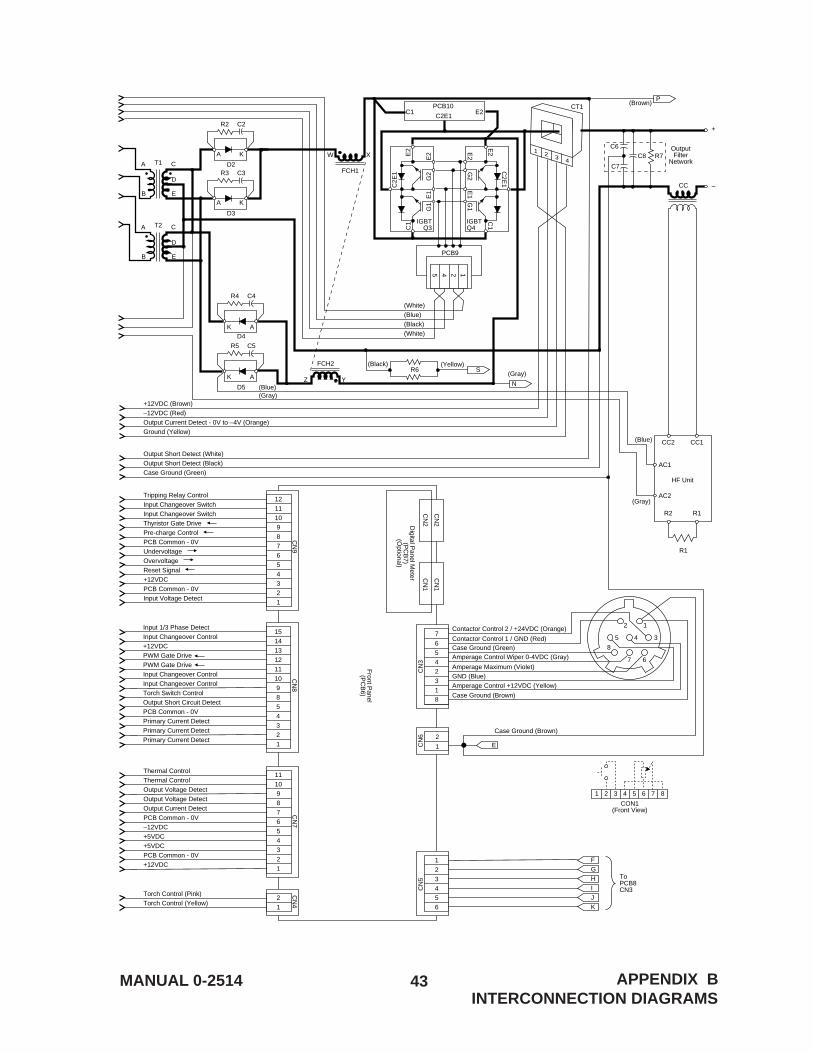
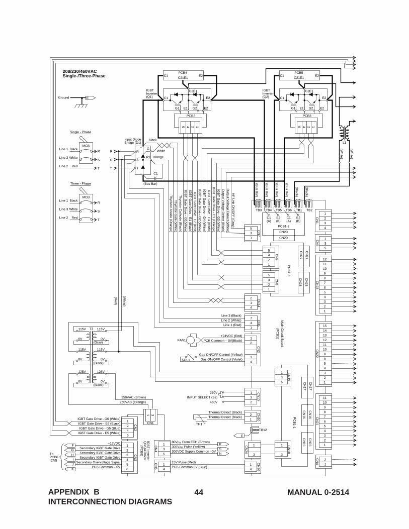
APPENDIX B – INTERCONNECTION DIAGRAMS
The following pages contain the interconnection diagrams for all 300GTSWmodels in current production, to aid in the identification of replacementparts.
APPENDIX BINTERCONNECTION DIAGRAMS
42 MANUAL 0-2514
1
3
CN
24
1
3
CN
18
R2
GR
S
T
C1
Orange
Black
White
(Bus Bar)
–
+
2
31
CN
13C
N2
Ground
PC
B1-1
Main C
ircuit Board
(PC
B1)
TB3 TB4 TB5 TB6 TB1
TB12
TB2
7
4
1
CN
16
CN
16
CN
17
CN
17C
N15
CN
15
CN
6
2
1
4
CN
14
5
4
2
1
CN
8
1
3
5
CN
4
80VPK From FCH (Brown)
300VPK Pulse (Yellow)
300VDC Supply Common –0V
15V Pulse (Red)
PCB Common 0V (Blue)
Line 3 (Black)
Line 2 (White)
Line 1 (Red)
Thyristor C
athode (Black)
Thyristor G
ate (White)
Thyristor A
node (Orange)
IGB
T G
ate Drive - G
2 (White)
IGB
T G
ate Drive - E
2 (Red)
IGB
T G
ate Drive - E
1 (Black)
IGB
T G
ate Drive - G
1(White)
IGBT Gate Drive - G6 (White)
IGBT Gate Drive - E6 (Black)
IGBT Gate Drive - G5 (Blue)
IGBT Gate Drive - E5 (White)
IGB
T G
ate Drive - G
3 (White)
IGB
T G
ate Drive - E
3 (Orange)
IGB
T G
ate Drive - E
4 (Black)
IGB
T G
ate Drive - G
4 (White)
Output V
oltage Detect (W
hite)
Output V
oltage Detect (B
lack)
HF
Unit O
N/O
FF
(Gray)
Thermal Detect (Black)
Thermal Detect (Black)
+12VDCSecondary IGBT Gate Drive
Secondary IGBT Gate Drive
Secondary IGBT Gate Drive
Secondary Overvoltage Signal
PCB Common – 0V
(Bus B
ar)
(Bus B
ar)
(Bus B
ar)
(Bus B
ar)
(Black)
(Black)
(White)
(White)
L1
FAN1
SOL1
5
4
2
1
CN
9
1
2
3
4
CN
1
1
3
5
CN
5
5
3
1
CN
7
2
1TH1
CN
10
1
4
CN
26
31
CN1
MCB
Single - Phase
Input DiodeBridge (D1)
1245
PCB2
PCB4E2
C2E1
C1
G1 E1 G2 E2
E2
C1
1245
PCB3
PCB5E2
C2E1
C1
IGBTInverter(Q2)
IGBTInverter(Q1)
208/230VAC Single-VoltageSingle-/Three-Phase
G1 E1 G2 E2
E2
C1C21E1C21E1
(Red)
(White)
250VAC (Brown)
250VAC (Orange)
E
Black
White
Red
Line 1
Line 3
Line 2
R
S
T
R
S
T
CN
22
12
11
10
9
8
7
6
5
4
3
2
1
11
10
9
8
7
6
5
4
3
2
1
CN
21
2
1
CN
4
1
4
CN
5
15
14
13
12
11
10
98
54
32
1
CN
23
1
2
34
+24VDC (Red)
PCB Common – 0V(Black)
Gas ON/OFF Control (Yellow)
Gas ON/OFF Control (Violet)
65432
1
CN
3
F
ToPCB6 CN5
G
H
P
E
E
S
N
I
J
K
1
2
4
5
IGB
T Inverter
Q3/Q
4 Driver
(PC
B8)
CN
2
MCB
Three - Phase
Black
White
Red
Line 1
Line 3
Line 2
R
S
T
(Gray)
(Black)
(Black)0V
125V
0V
125V
0V
115V
0V
115V
0V
115V
0V
115V
T3
APPENDIX BINTERCONNECTION DIAGRAMS
43MANUAL 0-2514 APPENDIX BINTERCONNECTION DIAGRAMS
CON1(Front View)
18
32456
7
1 2 3 4 5 6 7 8
Case Ground (Brown)
Case Ground (Brown)
Contactor Control 1 / GND (Red)
Contactor Control 2 / +24VDC (Orange)
Amperage Control +12VDC (Yellow)
GND (Blue)Amperage Maximum (Violet)
Amperage Control Wiper 0-4VDC (Gray)Case Ground (Green)
CN
3
8
7 6
35 4
2 1
CN
6
1
2
Digital P
anel Meter
(PC
B7)
(Optional)
Front P
anel(P
CB
6)
CN
2
CN
2
CN
1
CN
1
E
Tripping Relay Control
Input Changeover Switch
Input Changeover Switch
Thyristor Gate Drive
Pre-charge Control
PCB Common - 0V
Undervoltage
Overvoltage
Reset Signal
+12VDC
PCB Common - 0V
Input Voltage Detect
65432
1
CN
5
12
11
10
9
8
7
6
5
4
3
2
1
CN
9
Thermal Control
Thermal Control
Output Voltage Detect
Output Voltage Detect
Output Current Detect
PCB Common - 0V
–12VDC
+5VDC
+5VDC
PCB Common - 0V
+12VDC
11
10
9
8
7
6
5
4
3
2
1
CN
7
Torch Control (Pink)
Torch Control (Yellow)
(Blue)
(Gray)
(Blue)(Gray)
2
1
CN
4
Output Short Detect (White)
Output Short Detect (Black)
Case Ground (Green)
+12VDC (Brown)
–12VDC (Red)
Output Current Detect - 0V to –4V (Orange)
Ground (Yellow)
(Black) (Yellow)
(Gray)
T1A C
D
EB
A C
D
EB
T2
1 2 3 4
CT1
C6
C7
C8
+
OutputFilter
Network
–
R7
CC
FCH1
W X
AC1
AC2
CC2 CC1
R2 R1
R1
HF Unit
FCH2
Z Y
Input 1/3 Phase Detect
Input Changeover Control
+12VDC
PWM Gate Drive
PWM Gate Drive
Input Changeover Control
Input Changeover Control
Torch Switch Control
Output Short Circuit Detect
PCB Common - 0V
Primary Current Detect
Primary Current Detect
Primary Current Detect
15
14
13
12
11
10
9
8
5
4
3
2
1
CN
8
(White)
(Blue)
(Black)
(White)
D2
R2 C2
D3
R3 C3
A K
A K
D4
R4 C4
D5
R5
R6
C5
AK
AK
P(Brown)
S
N
1245
PCB9
IGBTQ3
IGBTQ4
PCB10E2C1
C2E1
F
ToPCB8CN3
G
H
I
J
K
C2E
1
C1
G1
E1
G2
E2E
2
C2E
1
C1
G1
E1
G2
E2
E2
44 MANUAL 0-2514APPENDIX BINTERCONNECTION DIAGRAMS
1
3
CN
24
1
3
CN
18
13
5
CN
19
R2
GR
S
T
C1
Orange
Black
White
(Bus Bar)
–
+
1
32
230V
INPUT SELECT (S2)
460V
CN
13C
N2
Ground
PC
B1-1
Main C
ircuit Board
(PC
B1)
PC
B1-3
PCB1-2
TB3
C1(A)
C1(A)
E2(B)
E2(B)
TB4 TB5 TB6 TB1
TB12
TB2
7
4
1
CN
16
CN
16
CN
17
CN
17C
N15
CN
15
CN
6
2
1
4
CN
14
1
3
5
CN
4
80VPK From FCH (Brown)
300VPK Pulse (Yellow)
300VDC Supply Common –0V
15V Pulse (Red)
PCB Common 0V (Blue)
Line 3 (Black)
Line 2 (White)
Line 1 (Red)
Thyristor C
athode (Black)
Thyristor G
ate (White)
Thyristor A
node (Orange)
IGB
T G
ate Drive - G
2 (White)
IGB
T G
ate Drive - E
2 (Red)
IGB
T G
ate Drive - E
1 (Black)
IGB
T G
ate Drive - G
1(White)
IGBT Gate Drive - G6 (White)
IGBT Gate Drive - E6 (Black)
IGBT Gate Drive - G5 (Blue)
IGBT Gate Drive - E5 (White)
IGB
T G
ate Drive - G
3 (White)
IGB
T G
ate Drive - E
3 (Orange)
IGB
T G
ate Drive - E
4 (Black)
IGB
T G
ate Drive - G
4 (White)
Output V
oltage Detect (W
hite)
Output V
oltage Detect (B
lack)
HF
Unit O
N/O
FF
(Gray)
Thermal Detect (Black)
Thermal Detect (Black)
+12VDC
Secondary IGBT Gate Drive
Secondary IGBT Gate Drive
Secondary IGBT Gate Drive
Secondary Overvoltage Signal
PCB Common – 0V
(Bus B
ar)
(Bus B
ar)
(Bus B
ar)
(Bus B
ar)
(Black)
(Black)
(White)
(White)
L1
FAN1
SOL1
1
2
3
4
CN
1
1
3
5
CN
5
5
3
1
CN
7
2
1TH1
CN
10
1
4
CN
26
31
CN1
MCB
Single - Phase
Input DiodeBridge (D1)
1245
PCB2
PCB4E2
C2E1
C1
G1 E1 G2 E2
E2
C1
1245
PCB3
PCB5E2
C2E1
C1
IGBTInverter(Q2)
IGBTInverter(Q1)
208/230/460VACSingle-/Three-Phase
G1 E1 G2 E2
E2
C1C21E1C21E1
250VAC (Brown)
250VAC (Orange)
E
Black
White
Red
Line 1
Line 3
Line 2
R
S
T
R
S
T
CN
22C
N21
2
1
CN
4
1
4
CN
5
15
14
13
12
1110
98
54
32
1
CN
23
CN
28
CN
28
CN
27
CN
27
CN20
CN20
1
2
3
4
+24VDC (Red)
PCB Common – 0V(Black)
Gas ON/OFF Control (Yellow)Gas ON/OFF Control (Violet)
65432
1
CN
3
F
ToPCB6 CN5
G
H
P
E
S
N
I
J
K
1
2
4
5
IGB
T Inverter
Q3/Q
4 Driver
(PC
B8)
CN
2
MCB
T3
Three - Phase
Black
White
Red
Line 1
Line 3
Line 2
R
S
T
5
4
2
1
CN
8
5
4
2
1
CN
9
(Gray)
(Black)
(Black)0V
125V
0V
125V
0V
115V
0V
115V
0V
115V
0V
115V
(Red)
(White)
12
11
10
9
8
7
6
5
4
3
2
1
11
10
9
8
7
6
5
4
3
2
1
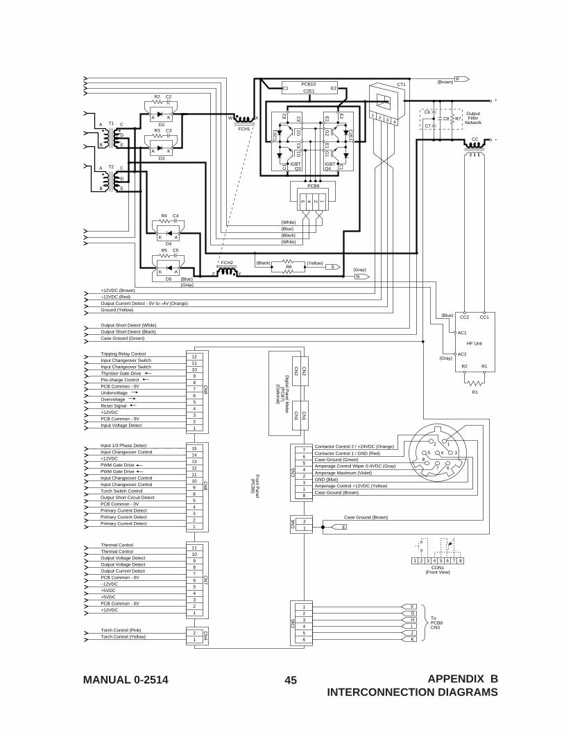
45MANUAL 0-2514 APPENDIX BINTERCONNECTION DIAGRAMS
CON1(Front View)
18
32456
7
1 2 3 4 5 6 7 8
Case Ground (Brown)
Case Ground (Brown)
Contactor Control 1 / GND (Red)
Contactor Control 2 / +24VDC (Orange)
Amperage Control +12VDC (Yellow)
GND (Blue)Amperage Maximum (Violet)
Amperage Control Wiper 0-4VDC (Gray)Case Ground (Green)
CN
3
8
7 6
35 4
2 1
CN
6
1
2
Digital P
anel Meter
(PC
B7)
(Optional)
Front P
anel(P
CB
6)
CN
2
CN
2
CN
1
CN
1
E
Tripping Relay Control
Input Changeover Switch
Input Changeover Switch
Thyristor Gate Drive
Pre-charge Control
PCB Common - 0V
Undervoltage
Overvoltage
Reset Signal
+12VDC
PCB Common - 0V
Input Voltage Detect
65432
1
CN
5
12
11
10
9
8
7
6
5
4
3
2
1
CN
9
Thermal Control
Thermal Control
Output Voltage Detect
Output Voltage Detect
Output Current Detect
PCB Common - 0V
–12VDC
+5VDC
+5VDC
PCB Common - 0V
+12VDC
11
10
9
8
7
6
5
4
3
2
1
CN
7
Torch Control (Pink)
Torch Control (Yellow)
(Blue)
(Gray)
(Blue)(Gray)
2
1
CN
4
Output Short Detect (White)
Output Short Detect (Black)
Case Ground (Green)
+12VDC (Brown)
–12VDC (Red)
Output Current Detect - 0V to –4V (Orange)
Ground (Yellow)
(Black) (Yellow)
(Gray)
T1A C
D
EB
A C
D
EB
T2
1 2 3 4
CT1
C6
C7
C8
+
OutputFilter
Network
–
R7
CC
FCH1
W X
AC1
AC2
CC2 CC1
R2 R1
R1
HF Unit
FCH2
Z Y
Input 1/3 Phase Detect
Input Changeover Control
+12VDC
PWM Gate Drive
PWM Gate Drive
Input Changeover Control
Input Changeover Control
Torch Switch Control
Output Short Circuit Detect
PCB Common - 0V
Primary Current Detect
Primary Current Detect
Primary Current Detect
15
14
13
12
11
10
9
8
5
4
3
2
1
CN
8
(White)
(Blue)
(Black)
(White)
D2
R2 C2
D3
R3 C3
A K
A K
D4
R4 C4
D5
R5
R6
C5
AK
AK
P(Brown)
S
N
1245
PCB9
IGBTQ3
IGBTQ4
PCB10E2C1
C2E1
F
ToPCB8CN3
G
H
I
J
K
C2E
1
C1
G1
E1
G2
E2E
2
C2E
1
C1
G1
E1
G2
E2
E2
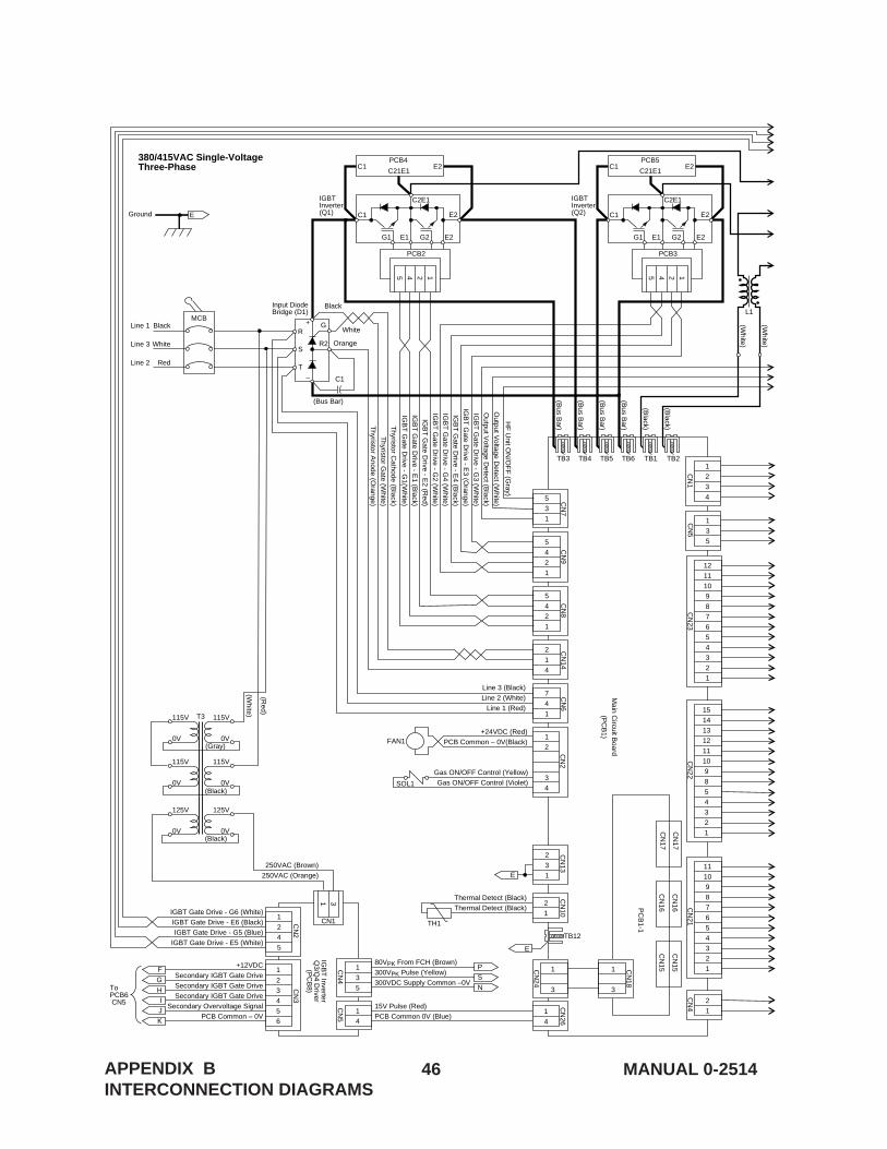
46 MANUAL 0-2514APPENDIX BINTERCONNECTION DIAGRAMS
1
3
CN
24
1
3
CN
18
R2
GR
S
T
C1
Orange
Black
White
(Bus Bar)
–
+
2
31
CN
13C
N2
Ground
PC
B1-1
Main C
ircuit Board
(PC
B1)
TB3 TB4 TB5 TB6 TB1
TB12
TB2
7
4
1
CN
16
CN
16
CN
17
CN
17C
N15
CN
15
CN
6
2
1
4
CN
14
5
4
2
1
CN
8
1
3
5
CN
4
80VPK From FCH (Brown)
300VPK Pulse (Yellow)
300VDC Supply Common –0V
15V Pulse (Red)
PCB Common 0V (Blue)
Line 3 (Black)
Line 2 (White)
Line 1 (Red)
Thyristor C
athode (Black)
Thyristor G
ate (White)
Thyristor A
node (Orange)
IGB
T G
ate Drive - G
2 (White)
IGB
T G
ate Drive - E
2 (Red)
IGB
T G
ate Drive - E
1 (Black)
IGB
T G
ate Drive - G
1(White)
IGBT Gate Drive - G6 (White)
IGBT Gate Drive - E6 (Black)
IGBT Gate Drive - G5 (Blue)
IGBT Gate Drive - E5 (White)
IGB
T G
ate Drive - G
3 (White)
IGB
T G
ate Drive - E
3 (Orange)
IGB
T G
ate Drive - E
4 (Black)
IGB
T G
ate Drive - G
4 (White)
Output V
oltage Detect (W
hite)
Output V
oltage Detect (B
lack)
HF
Unit O
N/O
FF
(Gray)
Thermal Detect (Black)
Thermal Detect (Black)
+12VDC
Secondary IGBT Gate Drive
Secondary IGBT Gate Drive
Secondary IGBT Gate Drive
Secondary Overvoltage Signal
PCB Common – 0V
(Bus B
ar)
(Bus B
ar)
(Bus B
ar)
(Bus B
ar)
(Black)
(Black)
(White)
(White)
L1
FAN1
SOL1
5
4
2
1
CN
9
1
2
3
4
CN
1
1
3
5
CN
5
5
3
1
CN
7
2
1TH1
CN
10
1
4
CN
26
31
CN1
Input DiodeBridge (D1)
1245
PCB2
PCB4E2
C2E1
C1
G1 E1 G2 E2
E2
C1
1245
PCB3
PCB5E2
C2E1
C1
IGBTInverter(Q2)
IGBTInverter(Q1)
380/415VAC Single-VoltageThree-Phase
G1 E1 G2 E2
E2
C1C21E1C21E1
(Red)
(White)
250VAC (Brown)
250VAC (Orange)
E
CN
22
12
11
10
9
8
7
6
5
4
3
2
1
11
10
9
8
7
6
5
4
3
2
1
CN
21
2
1
CN
4
1
4
CN
5
15
14
13
12
1110
98
54
32
1
CN
23
1
2
3
4
+24VDC (Red)
PCB Common – 0V(Black)
Gas ON/OFF Control (Yellow)Gas ON/OFF Control (Violet)
65432
1
CN
3
F
ToPCB6 CN5
G
H
P
E
E
S
N
I
J
K
1
2
4
5
IGB
T Inverter
Q3/Q
4 Driver
(PC
B8)
CN
2
MCBBlack
White
Red
Line 1
Line 3
Line 2
(Gray)
(Black)
(Black)0V
125V
0V
125V
0V
115V
0V
115V
0V
115V
0V
115V
T3

47MANUAL 0-2514 APPENDIX BINTERCONNECTION DIAGRAMS
CON1(Front View)
18
32456
7
1 2 3 4 5 6 7 8
Case Ground (Brown)
Case Ground (Brown)
Contactor Control 1 / GND (Red)
Contactor Control 2 / +24VDC (Orange)
Amperage Control +12VDC (Yellow)
GND (Blue)Amperage Maximum (Violet)
Amperage Control Wiper 0-4VDC (Gray)Case Ground (Green)
CN
3
8
7 6
35 4
2 1
CN
6
1
2
Digital P
anel Meter
(PC
B7)
(Optional)
Front P
anel(P
CB
6)
CN
2
CN
2
CN
1
CN
1
E
Tripping Relay ControlInput Changeover SwitchInput Changeover SwitchThyristor Gate DrivePre-charge ControlPCB Common - 0VUndervoltageOvervoltageReset Signal+12VDCPCB Common - 0VInput Voltage Detect
65432
1
CN
5
121110987654321
CN
9
Thermal ControlThermal ControlOutput Voltage DetectOutput Voltage DetectOutput Current DetectPCB Common - 0V–12VDC+5VDC+5VDCPCB Common - 0V+12VDC
1110987654321
CN
7
Torch Control (Pink)Torch Control (Yellow)
(Blue)
(Gray)
(Blue)(Gray)
21
CN
4
Output Short Detect (White)Output Short Detect (Black)Case Ground (Green)
+12VDC (Brown)–12VDC (Red)Output Current Detect - 0V to –4V (Orange)Ground (Yellow)
(Black) (Yellow)
(Gray)
T1A C
D
EB
A C
D
EB
T2
1 2 3 4
CT1
C6
C7
C8
+
OutputFilter
Network
–
R7
CC
FCH1
W X
AC1
AC2
CC2 CC1
R2 R1
R1
HF Unit
FCH2
Z Y
Input 1/3 Phase DetectInput Changeover Control+12VDCPWM Gate DrivePWM Gate DriveInput Changeover ControlInput Changeover ControlTorch Switch ControlOutput Short Circuit DetectPCB Common - 0VPrimary Current DetectPrimary Current DetectPrimary Current Detect
1514131211109854321
CN
8
(White)(Blue)(Black)(White)
D2
R2 C2
D3
R3 C3
A K
A K
D4
R4 C4
D5
R5
R6
C5
AK
AK
P(Brown)
S
N
1245
PCB9
IGBTQ3
IGBTQ4
PCB10E2C1
C2E1
F
ToPCB8CN3
G
H
I
J
K
C2E
1
C1
G1
E1
G2
E2E
2
C2E
1
C1
G1
E1
G2
E2
E2