stepi soviet 1
TRANSCRIPT

8/3/2019 Stepi Soviet 1
http://slidepdf.com/reader/full/stepi-soviet-1 1/298
NASA
Contractor Report 3579
AVRADCOM
Technical Report 82-A-9
A Comparative Study of Sovietvs. Western Helicopters
Part I- General Comparison of Designs
W. Z. Stepniewski
International Technical Associates, Ltd.
Upper Darby, Pennsylvania
Prepared for
Aeromechanics Laboratory
AVRADCOM Research and Technology Laboratories
Ames Research Center
under Contract NAS2-10062
N/LSANational Aeronautics
and Space Administration
Scientific and TechnicalInformation Branch
1983

8/3/2019 Stepi Soviet 1
http://slidepdf.com/reader/full/stepi-soviet-1 2/298
Even a superficial observation would indicate that there are basic differences in the Soviet and
Western design and operational philosophies of rotary-wing aircraft. On the other hand, one should
not be surprised to find a lot of commonality in the approach to various technical and operational
problems.
Inview ofthisanticipatedualityof similaritiesnddissimilarities,tbecomes especiallynterest-
ingto developa deeperunderstandingofthesubject.hiscan bc done by showing notonlyWHAT is
eitheratvarianceorinagreementintheSovietdesignand operationalhilosophyofhelicoptersith
thoseintheWest,but alsoWHY.
The need forsuch a comparativestudyof Sovietvs.Westernhelicoptersas recognizedby the
Researchand Technology Laboratoriesf the U.S.Army AviationR&D Command, cspcciaUyby Dr.RichardM. Carlson,DirectoroftheLabs.Consequently,a contracttoconductthistaskwas awarded
throughNASA to InternationalechnicalAssociates,td.,and Mr. Ronald A. Shinnwas designated
by the Labs asmonitor of theprojectforPartI,"GeneralComparison of Designs."Mr. Wayne D.
Mosher monitored thepreparationof PartIf,"Evaluationof Weight,Maintainability,nd Design
AspectsofMajorComponents."
The resultsof the tasksperformed arc presentedin thistwo-partreportas outlinedbelow:
PART I. GeneralComparison of Designs. Here basicdesignaspectsof existingSovietheli-
copters,as wellas hypotheticalhelicoptersrepresentingptimum configurationsescribedin the
Sovietbook, "Helicopters-SelectionfDesignParameters"by M.N. Tishchcnkoctallarccornparcd
withselectedesternrepresentatives.
PART If.Evaluationof Weight,Maintainabilitynd DesignAspectsof Major Components. In
thistask,a deepercomparativeinsightintodesignand operationalphilosophiessgainedby exam-
ining(a) weight-predictionethods and weight trends,(b) maintainability,c)overallmerits of
component designs,and (d) classificationnd rankingof helicopterconfigurationsor transport
operations.
In preparationforPartI,nineproductionand fourSoviethypotheticalelicopters,nd atotalof
fourteenWestern helicoptersepresentingross-weightlassesrangingfrom under 12,000 to over
100,000 pounds were includedinthestudy.Thisphaseofthework representedalookintotheover-
alldesignphilosophyof Sovietvs.Wcstcm helicopters.lso includedwas a comparison ofsixpro-
ductionand two hypotheticalSovietengines,nd thirteenesternengines,epresentingowcrplants
installednthecompared helicopters.
Upon completion of the above work, reviewcopiesof the reportwere printed(courtesyof
Boeing VertolCompany) in February 1981, and distributedo the manufacturersof theWestern
helicopterscontainedin the study,alongwith a requestthatthey reviewand correctthematerial
relatedto theirproducts,whilethematerialrelatedtoRussianhelicoptersnd engineswas submitted
to the U.S.Army ForeignScienceand Technology Centerfortheircomrncntsand suggestions.he
responsewas very good, and valuableadditionalinformation,as well as basicup-to-datedata was
obtainedand incorporatedintothefinalreport.
iii

8/3/2019 Stepi Soviet 1
http://slidepdf.com/reader/full/stepi-soviet-1 3/298
In preparation for Part I of the Comparative Study of Soviet vs. Western Helicopters, nine
production and four hypothetical Soviet helicopters, and a total of fourteen Western helicopters
representing gross weight classes ranging from 12,000 to over 100,000 pounds were included in the
study. This phase of the work represented a look into the overall design philosophy of Soviet vs.
Western helicopters. A comparison of six production and two hypothetical Soviet engines, and
thirteen Western engines, representing powerplants installed in the compared helicopters were also
included.
Upon completion of the above work, review copies of the report were printed (courtesy of
Boeing Vertol Company) in February 1981, and distributed to the manufacturers of the Western
helicopters contained in the study, along with a request that they review and correct the material
related to their products, while the material related to Russian helicopters and engines was submitted
to the U.S. Army Foreign Science and Technology Center for their comments and suggestions. The
response was very good, and valuable additional information, as well as basic up to date data was
obtained, and incorporated into the final report.
In the meantime, the Mil Mi-26 heavy-lift transport helicopter with the Lotarev D-136 turbo-
shaft engine was unveiled at the Paris Air Show in June, 1981, A comparison of this helicopter and
engine with the corresponding hypothetical machine postulated by Tishchenko et al 1 indicated that
the hypothetical aspects contained in his book actually represented milestones and goals for the
new generation of Soviet helicopters and engines. Taking advantage of the valuable additional
information regarding the Mi-26 and the D-136 turboshaft, the undersigned has included the extra
helicopter data along with its 'conceptual prototype' -the hypothetical 52-ton single rotor heli-
copter (referred in this work as the Hypo 52-SR), while the information available to date on the
D-136 turboshaft is contained in the powerplant comparison.
The revision of Part I of 'A Comparative Study of Soviet vs. Western Helicopters' was made
possible by the contributions of the manufacturers of Western helicopters as represented by Aero-
spatiale, Bell Helicopter Textron, Boeing Vertol Company, Messerschmitt-Boelkow-Blohm GmbH,
and Sikorsky Aircraft. Other contributors include Dr. R. M. Carlson who continuously served as a
source of inspiration and valuable suggestions, and Mr. R. A. Shinn who, in his capacity as technical
and administrative monitor, greatly contributed to the concept formulation of the study and its
execution. The editors are grateful to Mr. R. D. Semple of Boeing Vertol, Mr. H. D. Wilsted of the
Research and Technology Labs, and Mr. E. R. Mclnturff for their expert review and valuable sugges-
tions. Our appreciation and sincere thanks are extended to all of the above companies and individuals.
The text of this volume was set by Mrs. W. L. Metz of ITA, who also assisted with editorial
aspects.
Upper Darby, Pa., USA
July 30, 1981
W. Z. Stepniewski
iv

8/3/2019 Stepi Soviet 1
http://slidepdf.com/reader/full/stepi-soviet-1 4/298
page
Preface ................................................. iii
List of Syrnbols .............................................. ix
1.1
1.2
1.3
1.4
1.5
1.6
1.7
1.8
Chapter 1 Introductory Considerations
Objectives ................................................. 1
Helicopter Groups ............................................ 2Selection of Gross Weight ........................................ 4
Design Effectiveness Criteria for Hovering and Vertical Climb ................... 4
Design Effectiveness Criteria for Forward Flight ........................... 8
Some Aspects of Design Philosophy .................................. 19
Configurational Aspects ......................................... 20
Concluding Remarks ........................................... 26
2.1
2.2
2.3
2.4
2.5
2.6
Chapter 2 Powerplants
Introduction ................................................ 29
Auxiliary Relationships ......................................... 30
Comparison of Engines Installed in Helicopters of up to 12,000-1b Gross Weight Class ..... 33
Comparison of Engines Installed in 12,000 to 30,000-1b Gross Weight Class Helicopters .... 40
Comparison of Engines Installed in the 30,000 to lO0,O00-1b and Over 100,000-1b
Gross Weight Class Helicopters .................................... 46
Concluding Remarks ............................................ 48
3.1
3.2
3.3
3.4
3.5
3.6
3.7
Chapter 3 Helicopters of the Up-to-12,000-lb Class
Basic Data ................................................. 55
Hovering and Vertical Climb Aspects .................................. 68
Energy Aspects in Hover ......................................... 79
SHP Required Aspects in Level Flight at SL, ISA ........................... 83
Energy Aspects in Forward Flight ................................... 89
Productivity ............................................... 100
General Discussion and Concluding Remarks ............................ 100
4.1
4.2
Chapter 4 Helicopters of the 12,000 to 30,000-1b Gross Weight Class
Basic Data ................................................ 103
Hovering and Vertical Climb Aspects ................................. 113
V

8/3/2019 Stepi Soviet 1
http://slidepdf.com/reader/full/stepi-soviet-1 5/298
4.3
4.4
4.5
4.6
4.7
Energy Aspects in Hover ....................................... 129
SHP Required Aspects in Level Flight at SL, ISA ......................... 133
Energy Aspects in Level Flight, SL, ISA .............................. 140
Productivity .............................................. 147
General Discussion and Concluding Remarks ........................... 147
Appendix - Chapter 4 ........................................ 153
5.1
$.2
5.3
5.4
5.5
5.6
5.7
5.8
Chapter 5 30,000 to lO0,000-1b GW Helicopters
Hypothetical Helicopters ....................................... 154
Basic Data ............................................... 159
Hovering and Vertical Climb Aspects ................................ 168
Energy Aspects in Hover ....................................... 180
SHP Required Aspects in Level Flight at SL, ISA ......................... 184
Energy Aspects in Level Flight, SL, ISA .............................. 196
Productivity .............................................. 204
General Discussion and Concluding Remarks ........................... 204
6.1
6.2
6.3
6.4
6.5
6.6
6.7
6.8
Chapter 6 Over lO0,O00-1b Gross Weight Helicopters
Compared Helicopters ........................................ 210
Basic Data ............................................... 218
Hover and Vertical Climb Aspects ................................. 225
Energy Aspects in Hover ....................................... 235
SHP Required Aspects in Level Flight at SL ............................ 235
Energy Aspects in Level Flight, SL, ISA .............................. 242
Productivity .............................................. 249
General Discussion and Concluding Remarks ........................... 253
Append/:< - Chapter 6 ........................................ 255
Chapter 7 Overview of Design Parameters and Performance
7.1
7.2
7.3
7.4
7.5
7.6
Introduction .............................................. 260
Principal Design Parameters ..................................... 260
Weight Aspects ............................................ 265
Hovering Aspects ........................................... 270
Forward Flight Aspects ....................................... 270
Energy Aspects ............................................ 280
References ..................................................... 287
vi
8/3/2019 Stepi Soviet 1
http://slidepdf.com/reader/full/stepi-soviet-1 6/298
Evena superficial observation would indicate that there are basic differences in the Soviet
and Western design and operational philosophies of rotary-wing aircraft. On the other hand, one
should not be surprised to find a lot of commonality in the approach to various technical and
operational problems.
In view of this anticipated duality of similarities and dissimilarities, it becomes especially
interesting to develop a deeper understanding of the subject. This can be done by showing not only
WHAT is either at variance or in agreement in the Soviet design and operational philosophy of
helicopters with those in the West, but also WHY.
The need for such a comparative evaluation and analysis was recognized by the Research and
Technology Laboratories of the U.S. Army Aviation R&D Command; especially by Dr. Richard M.
Carlson, Director of the Labs. Consequently, a contract to conduct this task was awarded through
NASA to International Technical Associates, Ltd., and Mr. Ronald A. Shinn was designated by the
Labs as monitor of the project.
The study is divided into several separate tasks, and the results are presented in this report
which consists of the three parts outlined below.
Part 1. General Comparison of Designs
Here, basic design aspects of existing Soviet helicopters, as well as hypothetical helicopters
representing optimum configurations as set forth in Tishchenko's et al studies I are compared with
selected representatives of the West.
Part II. Evaluation of Major Components and Their Weight-Prediction Methods
In this task, a deeper comparative insight into design and operational philosophies is gained by
examining the following aspects of the major components of Soviet and Western helicopters.
(a) weight trends and weight-prediction methods
(b) conceptual approach
(c) producibility and maintainability.
Part III. Ranking of Large Single and Multirotor Transport Helicopters
The final comparison is made of Soviet vs. Western approaches to helicopter design using
Tishchenko's method of ranking large helicopters of various configurations with respect to a few
selected short and long-haul cargo transport missions. This task will be performed by using both
Soviet and Western constraints and minimal performance requirements, and the weight trend pre-
diction methods indicated in Part II.
vii
8/3/2019 Stepi Soviet 1
http://slidepdf.com/reader/full/stepi-soviet-1 7/298
In themeantime,heMilMi-26heavy-liftransportelicopter iththeLotarevD-136urbo-shaftengineas unveiled at the Paris Air Show in June 1981. A comparison of this helicopter and
engine with the corresponding hypothetical machine postulated by Tishchenko et al I indicated thatthe hypothetical aspects contained in his book actually represented milestones and goals for the
new generation of Soviet helicopters and engines. Taking advantage of the valuable additional in-
formation regarding the Mi-26 and D-136 turboshaft, the undersigned has included the extra heli-
copter data along with its 'conceptual prototype' - the hypothetical 52-ton single-rotor helicopter
(referred to in this work as the Hypo 52-SR), while the information available to date on the D-136
turboshaft is contained in the powerplant comparison.
The revision of Part I of "A Comparative Study of Soviet vs. Western Helicopters" was made
possible by the contributions of the manufacturers of Western helicopters as represented by Aero-
spatiale, Bell Helicopter Textron, Boeing Vertol Company, Messerschmitt-Boelkow-Blohm GmbH,
and Sikorsky Aircraft. Other contributors include Dr. R.M. Carlson who continuously served as a
source of inspiration and valuable suggestions, and Mr. R.A. Shinn who, in his capacity as technical
and administrative monitor, gready contributed to the concept formulation of the study and its
execution. The editors are grateful to Mr. R.D. Semple of Boeing Vertol, Mr. H.D. Wilsted of the
Research and Technology Labs, and Mr. E.R. Mclnturff of the U.S. Army Foreign Science and
Technology Center for their expert review and valuable suggestions. Our appreciation and sincere
thanks are extended to all of the above companies and individuals. The text of this report was set by
Mrs. W.L. Metz of ITA, who also assisted with editorial aspects.
W. Z. Stepniewski
Upper Darby, Pa. USA
July 30, 1981
viii

8/3/2019 Stepi Soviet 1
http://slidepdf.com/reader/full/stepi-soviet-1 8/298
A
b
Co
CLCpCT
Cw
C
-ca
0
D e
f
FF
FF w
PFm o
FM
FMoa
GW
H
h
HFF
HH
HP
kblo
keng
hind
kpc
kv
L
M
NGW
n
OGE
PL
PH
total rotor(s) swept area; sq.ft
wing aspect ratio
number of blades
wing drag coefficient
wing lift coefficient
power coefficient: Cp - 550 HP/A p Vt 3
thrust coefficient: C r =- T/A p V_
gross-weight coefficient: C w =- Wgr/A p V_
chord, blade or wing; ft
average blade profile drag coefficient
average blade-lift coefficient: "cQ---6CT/O
diameter; ft
drag; lbequivalent helicopter drag: D e =-32551-P/V; lb
equivalent flat-plate area; sq.ft
fuel flow; lb/unit of time
fuel required per lb of gross weight & 100 n.mi
fuel required per lb of zero-range payload & 100 n.mi
rotor figure of merit
helicopter overall figure of merit: FMoa = RPid/SP
gross weight; lb
altitude; ft
height; ft
hourly fuel flow; Ib/hr
horizontal hinge
horsepower; hp
blocking effect coefficient
engine weight coefficient
rotor induced power coefficient: kin d =- RPind/RPid
climb efficiency factor
download coefficient: k v = Tmr/War
distance; ft
lift; lb
length; ft
distance; n.mi
Much number
normal gross weight; lb
number
out-of-ground effect
payload; lb
pitch-bearing housing
ix

8/3/2019 Stepi Soviet 1
http://slidepdf.com/reader/full/stepi-soviet-1 9/298
PI
R
RP
RHP
R/C
S
SP
SHP
sfc
T
t
V
e
Vt
Vcab
VII
V
W
W
X
X
Y
Y
productivity index: P/= Vcr Wpl/W e
rotor radius; ft
rotor power: ft-lb/sec, or hp
rotor horsepower; hp
rate of climb; fps, or fpm
area; sq.ft
shaft power; ft-lb/sec, or hp
shaft horsepower; hp
specific fuel consumption; lb/hr-hp
rotor thrust; lb
time; sec, min, or hr
speed of flight; kn
rate of climb; fps or fpmtotal rate of ideal flow through the disc; fps
rotor tip speed; fps
cabin volume; cu.ft
vertical hinge
induced velocity; fps
weight; lb or kg
disc, and area loading; psf
tail-rotor distance from main-rotor shaft; ft
relative tail-rotor distance from main-rotor shaft: x = x/R
tail-rotor elevation over main-rotor hub; ft
relative tail-rotor elevation: _ ==-y/R
O_
A
770 a
17xm
/J
P
(7
relative fuel flow at idle
angle-of-attack; deg or rad
slope of relative fuel flow vs partial power setting
increment
overall rotor-power transmission efficiency: rloa =- RP/SP
transmission efficiency
relative engine power lapse rate with altitude
wingqift to total-lift ratio
rotor advance ratio: /a = 1.69 V/V t
air density; slugs/cu.ft
rotor solidity; a = bc/rrR
Subscripts:
act
av
c
actual
available, or average
climb

8/3/2019 Stepi Soviet 1
http://slidepdf.com/reader/full/stepi-soviet-1 10/298
cont
cr
e
eng
f
fp
fu
gr
H
h
hc
id
ind
mr
NR
0
p
ref
req
ro t
$c
TO
t
tab
tf
tr
VTO
V
W
xm
e
continuous
cruise
crnpty
minimum power (approx. maximum endurance)
cnginc
forward
flat plate
fuel
gross
altitude
hovering
hovering ceiling
ideal
induced
main rotor
normal rated
initial value
sea level
payload
reference
required
rotor
serviceceiling
takeoff
time
tip
tip of advancing blade
trapped fluid
tail rotor
vertical takeoff
vertical; at speed of flight V
gross weight
wing
transmission
e=-(wa,/o_)_ _
xi

8/3/2019 Stepi Soviet 1
http://slidepdf.com/reader/full/stepi-soviet-1 11/298
Chapter 1
Introductory Considerations
1.1 Objectives
The principal aim of this chapter is to make a general comparison of the state of the art of Soviet
helicopter design vs. that of the West (U.S. in particular), and to indicate both commonalities and differ-
ences in conceptual design philosophies existing in those two politically, economically, and to some extent,
climatically and geographically different groups.
There are two basic aspects of the comparison:
(1) Presentation of important design parameters, and (2) evaluation of the overall design effective-
ness according to various criteria.
With respect to the first of these tasks, it is performed by simply presenting, numerically and often
graphically, such input parameters as: (a) disc loading, (b) installed (TO) and transmission-limited power
loading, (c) tip speeds, (d) number of blades, blade aspect ratios, and rotor solidities, (e) relative location
of the tail rotor, and tall-rotor to main-rotor radii ratio, (f) Cr/o and/or Fz in the considered regimes of
flight*, and (g) cabin dimensions.
As far as task (2) is concerned, again simple listing and suitable graphical presentation of performance
would, by itself, provide some clues regarding the success of design. Here, the following items come to one's
mind: (a) hovering ceiling, OGE vs. gross weight; (b) rate of vertical climb; (c) forward flight rate of climb,
with all engines operating; (d) service ceiling with all engines operating, and one engine out; (e) maximum
and cruise speeds of flight i and (f) payload, and corresponding range.
This cursory design evaluation can be further improved by graphically presenting such power-
dependent performance items as hovering ceilings, rates of climb, and flight speeds as a function of installed
or transmission-limited power loading.
However, in order to gain a still deeper insight into the overall design effectiveness (aerodynamics,
weights, and powerplants), more detailed criteria are established and discussed, and particular helicopters
are judged according to them.
*Items (a), (c), (d), and (f) refer to both lifting and tail rotors.

8/3/2019 Stepi Soviet 1
http://slidepdf.com/reader/full/stepi-soviet-1 12/298
Sincepowerplantsepresentn important contribution to the success or failure of rotorcraft, one
chapter is devoted to the comparison of the most important characteristics of both Soviet and Western
engines, and the accumulation of engine performance information necessary for further helicopter evalua-
tion. Consequently, such items are examined as various power ratings; specific weight; specific fuel con-
sumption, and its variation with power setting; and external dimensions. However, the powerplant com-
parisons are not as indepth as those for the rotorcraft as a whole.
In concluding these general introductory remarks, it should be emphasized that in addition to the
comparison of Soviet and Western helicopter designs, supplemental benefits from this study should be
acquired through an accumulation (under a single cover) of data representing values and ranges of various
design parameters, and acquisition of numerical evaluation of the most important aspects of the overall
design efficiency. All this material should be of significant help to the designers of new rotary-wing air-
craft as well as to those who teach academic courses on helicopter design.
1.2 Helicopter Groups
In order to improve the significance of the comparative process, all examined helicopters are grouped
according to their design gross weight as follows:
(1) Up to 12,000-1b gross weight class
(2) 12,000 to 30,000-1b gross weight class
(3) 30,000 to 100,000-1b gross weight class
(4) Higher than 100,000-1b gross weight class.
Once the above classification was accepted, it was not difficult to properly group existing Soviet
helicopters on which published data are available. Also it was possible to incorporate the hypothetical
helicopters considered in Tishchenko's et al book I into suitable gross weight classes.
As far as Western designs are concerned, it appeared desirable to include both U.S. and European
rotorcraft and, in that process, to select representatives of the most recent, as well as earlier designs.
As a result of this approach, the following groups were formed for comparison:
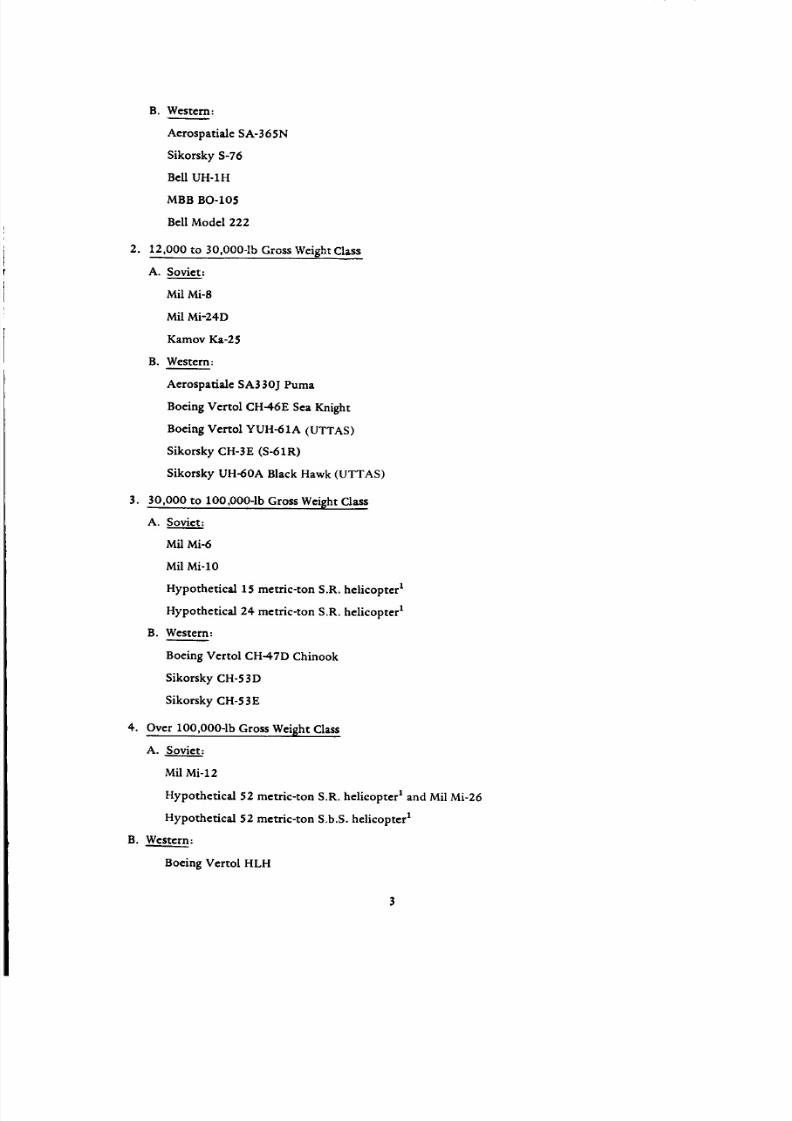
1. Up to 12,000-1b Gross Weight Class
A. Soviet:
Mil Mi-2 (original version as produced by PZL, Swidnik, Poland)
Mil Mi-2-A (with 2 Allison 250-C20B engines (PZL))
Kamov Ka-26
8/3/2019 Stepi Soviet 1
http://slidepdf.com/reader/full/stepi-soviet-1 13/298
B. Western:
Aerospatiale SA-365N
Sikorsky S-76
Bell UH-1H
MBB BO-105
Bell Model 222
2. 12,000 to 30,000-1b Gross Weight Class
A. Soviet:
Mil Mi-8
Mil Mi-24D
Kamov Ka-25
B. Western:
Aerospafiale SA330J Puma
Boeing Vertol CH-46E Sea Knight
Boeing Verrol YUH-61A (UTTAS)
Sikorsky CH-3E (S-61R)
Sikorsky UH-60A Black Hawk (UTTAS)
3. 30,000 to 100,000-Ib Gross Weight Class
A. Soviet:
Mil Mi-6
Mil Mi-lO
Hypothetical 15 metric-ton S.R. helicopter t
Hypothetical 24 metric-ton S.R. helicopter 1
B. Western:
Boeing Vertol CH-47D Chinook
Sikorsky CH-53D
Sikorsky CH-53E
4. Over lO0,O00-1b Gross Weight Class
A. Soviet:
Mil Mi-12
Hypothetical 52 metric-ton S.R. helicopter t and Mil Mi-26
Hypothetical 52 metric-ton S.b.S. helicopter t
B. Wester_......__n:
Boeing Vertol HLH

8/3/2019 Stepi Soviet 1
http://slidepdf.com/reader/full/stepi-soviet-1 14/298
1.3 Selection of Gross Weight
Absolute performance of helicopters as well as their relative rating can be strongly affected by their
flying gross weight values. Consequendy, it becomes important to establish a common ground for the
selection of gross weights to be used in this comparative study.
Normal gross weight appears as one of the possibilities, since performance figures published in such
reference texts as Jane's 2, Blue Book 3 and manufacturers brochures are often quoted for this gross weight
value. Unfortunately, this weight is often determined around some specific missions, which may be dif-
ferent for various helicopters and thus the normal gross weight may not represent a truly common ground
for this comparative evaluation.
Maximum operational flying weight as specified by the manufacturer and usually quoted in such
references as 2 and 3, as well as helicopter brochures, forms a somewhat better gross weight basis since it
is directly associated with the practical maximum load-carrying capacity of the rotorcraft. Hence, it will
be selected as the principal flying gross weight in this study.
However, one may object to this approach on the ground that helicopters are,first of all, VTO air-
craft, and as such should have the capability to take off vertically and/or hover OGE under specified
pressure altitudes and ambient temperature conditions. In order to satisfy these aspects, the following
is proposed:
VTO gross weight will be defined as a gross weight corresponding to hovering OGE at 3000 ft, ISA.
Should the so-defined VTO gross weight of a helicopter be lower than its maximum operational value, then
some of the comparative performance items will be recalculated for that supplemental gross weight in order
to show how adherence to the VTO capabilities would alter the relative standing of that helicopter with
respect to the others.
1.4 Design Effectiveness Criteria for Hovering and Vertical Climb
Overall Figure of Merit. Overall aerodynamic and configurational effectiveness of design in hover
can be evaluated through the Overall Figure of Merit (FMoa) which can be defined as a ratio of the ideal
power required in hovering (liPid = WgrVr-'_h/550) to the actual shaftpower delivered by the engines in
that regime of flight OGE.
FMoa = HPidlSHPre q (1.1)
The ideal power is easily determined, as the disc loading (w) of lifting rotor(s) and air density (p_)
in hovering are readily obtainable. As to the total engine S/-/P required under these circumstances, in some
cases, flight test results will be available which either give the desired relationship of SHPreqn = f(Wg r)
directly, or in a coefficient form as Cp = f(Cr). Should such direct relationship be not available, then
this difficulty can be surmounted by assuming that the hovering ceiling is associated with the TO power

8/3/2019 Stepi Soviet 1
http://slidepdf.com/reader/full/stepi-soviet-1 15/298
rating.Consequently,ncehemanufacturer'srassumed lapse-rate for the engines is known, the SHPTo
at hovering ceiling can be obtained. From this, the shaft horsepower per pound of gross weight (SHP/Wg r)
at the hovering ceiling can be calculated, and Eq (1.1) is rewritten as follows:
FMoa = wV/-w-_-Phc/550(SHPIWgr)hc (1.1a)
For the compared helicopters the above quantity can be tabulated as well as presented graphically.
Determination of VTO Gross Weight. Once the FMoa values are found, their knowledge can greatly
facilitate establishment of the VTO gross weight:
Assuming that the FMoa value remains approximately constant within possible gross weight (main
rotor thrust) and density variation limits, the shaft horsepower required to hover OGE at 3000 ft, ISA
by a single-rotor helicopter can be expressed as
SHPreqh = Wgr4Wgr/_'KR2mr P3000/550 FMoa
where Rmr is the main rotor radius and air density P3000 = 0.002175 slugs/ft 3 .
On the other hand, knowing the lapse rate (;ka000) of the takeoff power at 3000 ft, the TO shaft
horsepower available at that altitude becomes
SHPavh = Laooo(SHPTO)o
where SHPTo is the takeoff power at SL, ISA. Should the so-obtained power be higher than the trans-
mission limit, then the latter becomes the power available.
Equating the right sides of the above equations and solving for Wgr, the sought VTO gross weight is
obtained: *
(Wgr)vT 0 = 16.05[(SHPTO)okaOO ° Rm r FMoa ] 2/3 (1.2)
Hourly Fuel Consumption in Hover at SL, ISA per Pound of Paylo_uL The Overall Figure of Merit
permits one to judge only some aspects of the success of design of a helicopter as a hover vehicle. Such
important aspects of design effectiveness as the ability to carry the highest possible payload (at a given
gross weight) and, when doing that, use as litde energy (fuel) as possible per pound of payload and unit
of rime are not reflected through the FMoo values. In order to eliminate those shortcomings, the following
criterion is proposed: hourly fuel flow in hover at SL,ISA per pound of payload.
It is suggested that the above quantity be computed for the range of hypothetical payloads starting
with that corresponding to zero and ending at one hour of hover time.
Since weight empty and crew number are known for all helicopters being compared, the zero hover
time payload can be determined as
• .For tandeme and Ilde-by-llde configuration=, a con=tent coefficient of 20.22 would replace the 16.05 in Eq (1. 2).

8/3/2019 Stepi Soviet 1
http://slidepdf.com/reader/full/stepi-soviet-1 16/298
(wpl)t=o = wgr - we- Wcr,w- wt_ (1.3)
where Wgr is the gross weight selected as a basis for comparison; i.e, either (Wgr)ma x or (Wgr)vTO; We
is the weight empty; Wcrew is the crew weight; and Wti is the weight of trapped fluids.
It should be noted that in addition to the We/Wg r ratio, the (Wpl)t=o/Wg r ratio also represents an
interesting criterion of the weight effectiveness of design and thus both relationships should be shown
in tabulated and graphical form.
In regard to the relative hourly fuel consumption in hover (HFF/Wol), it is suggested that in order
to apply this criterion under uniform conditions, the HFF/Wpl quantity should be computed for hover
OGE at SL/1SA, either at the maximum flying weight, (Wgr)ma x, or at the VTO gross weight should the
latter be lower than (Wgr)ma x .
Once the FMoa values are known, the hourly fuel flow can be obtained as follows:
HFF = (Wgr WVr-_o/SSOFMoa)Sfc (1.4)
However, in order to complete the calculations indicated by Eq (1.4), the power required in hover
as given by the expression in the parenthesis in Eq (1.4) must be computed first, which would permit one
to find the partial power setting and the corresponding sfc values.
The needed (Wpl)t= 0 value is computed from Eq (1.3), while for time (hours) in hovering t > 0,
the payload is calculated as
(Wpl)t = (Wpl)t= 0 -- HFFt (1.5)
The (HFF/Wpl) = f(t) curve can be obtained from Eqs (1.4) and (1.5). This relationship for the compared
helicopters can be graphically presented as in Fig. 1.1.
Z
o
a.
(/3Z
G.o
...]
tr- rv
o-1-
0
SOVIET (BOLD)
WESTERN (THIN)
TIME IN HOURS
Figure 1.1 Relative hourly fuel flow vs. hover time for the compared helicopters

8/3/2019 Stepi Soviet 1
http://slidepdf.com/reader/full/stepi-soviet-1 17/298
Vertical Rate of Climb at SL, ISA. Values of vertical R/C at SL, ISA are not always given in published
literature, but knowledge of that performance item may be desirable when comparing various helicopters.
Here, again, knowledge of the FMoa values can greatly facilitate quick estimates of the vertical rate of
climb.
As indicated in Ch II of Ref 4, the total rate of the ideal flow through the disc V' in fps is
V' = 550 RHPid/Wg r (1.6)
but
and
RHPid = SHPFMoa
V' = 550FMoa/(Wgr/SHP) (1.6a)
This total flow rate is, in turn, equal to the sum of the ideal induced velocity vial and rate of vertical
climb (Vcv):
or
V' = rid + VCv (1.7)
Vcv = V _ __ rid
In turn, Vial Can be expressedas follows:
Vid = w/2p V'
(1.7a)
(].S)
or, in light of Eq (1.6a)
Via = w(Wgr/SHP)/I100pFMoa (1.8a)
Substituting Eqs (1.6a) and (1.8a) for V' and Vid respectively, into Eq (1.7a), and expressing the rate
of climb in fpm, the following is obtained:
Vcv = 60{ [550FMoa/(Wgr/SHP)] - [w(Wgr/SHP)/llOOpFmoa] } (1.9)
It can be seen from this equation that knowing the overall figure of merit (FMoa) and power loading
(Wgr/SHP) - in this case, at the T.O or transmission-limited rating-the vertical rate of climb can readily be
computed and properly tabulated for the purpose of comparison.
Hovering Ceiling. Hovering ceiling (OGE and IGE) in itself represents an important performance item.
However, when plotted on the abscissa of the T.O power loading, it may be considered as a design effi-
ciency criterion, showing how well the available power is actually utilized for achieving various hover
altitudes. A scheme of graphical presentation of the hovering ceilings for the purpose of comparison is
depicted in Fig. 1.2.

8/3/2019 Stepi Soviet 1
http://slidepdf.com/reader/full/stepi-soviet-1 18/298
F-it
Z
--I
otw
>O
WEST
(THIN)
,-" I
T.O SHP LOADING,
SOV I ET
(BOLD)
i.u
ILB/HP
Figure 1.2 Hovering ceiling vs. power loading of the compared helicopters
1.5 Design Effectiveness Criteria for Forward Flight
Shaft Horsepower per Pound of Gross Weight vs Flight Speed. Shaft horsepower per pound of gross
weight computed at a selected altitude (say, SL, ISA) and gross weight values (in our case, maximum)
and presented vs. speed of flight can be taken as a valuable criterion for comparing aerodynamic and con-
figurational effectiveness of various helicopters. An auxiliary grid of the weight to the equivalent drag,
(W/D e) = cons& lines would permit one to assess at a glance the (W/De)ma x values of the compared air-
craft.
As for the comparison of the Soviet vs. Western helicopters, graphical presentation of the (SHP/Wg r) =
f(V) curves will be such that referring to the Soviet machines will be plotted in heavy, while the Western
machines wiU be plotted in thin, lines; thus providing a background for the candidate helicopters (Fig 1.3).
---'---" SOVIET [BOLD]
..... <
ii
SPEED OF FLIGHT, KN
Figure 1.3 Comparison of (SHP/Wg r) = f(V) curves for the Soviet and Western helicopters

8/3/2019 Stepi Soviet 1
http://slidepdf.com/reader/full/stepi-soviet-1 19/298
Establishment of the (SliPWar) -- f(V) Relationship. For some Western helicopters, actual flight
test data on SHP vs. flying speed, or manufacturers' predicted figures are available. However, this informa-
tion could be for a different gross weight and/or altitude than required for this comparative study. For
Soviet rotorcraft, the SHP = f(V) relationships are not available as a rule. Consequently, there is a need
for (a) the ability to recalculate the (SHP/Wg r) = f(V) relationships from one altitude and gross weight
condition to another, and (b) to reconstruct the (SHP/Wgr) = f(V) curve from obtainable officially pub-
lished figures on flying speed at various gross weights and altitudes, and only generally defined power
settings (e.g., cruise, economic cruise). Additional information can be provided by the (usually given)
maximum rate of climb at SL, ISA and presumably, maximum continuous power setting.
An analytical basis for accomplishment of tasks (a) and (b) is provided by the following equation,
derived from Eqs (3.106) and (3.107) of Ref. 4.
(SHP/Wg r) = 2.413p -- + 0.296 +Wfp p V _ Vt 550Tloa (1.10)
where V is the flight speed in kn; hvf is the download factor; hindf is the induced power factor; w is the disc
loading in psf; wfp = Wgr/f is the equivalent flat-plate area (f) loading in psf;/a = 1.69V/V r is the advance
ratio; Vt is the tip speed in fps; p is the flight air density in slugs/cu.ft; (Fd/'f _ ) is the ratio of the average
profile drag to the average lift coefficient in hover; and 77oa is the overall rotor power transmission effi-
ciency representing the ratio of the rotor to shaft power.
Actually, in Eq (1.10) there are five unknowns (wfp, kvf, hindf, (fa/ 'fQ), and r/oa). It is evident hence,
that in order to determine all of them, five pairs of ($HP, V) points should be known. However, not all of
these unknowns are equally important for a correct reconstruction of the (SHP/Wg r) = f(V) curve. For
instance, it may be safely assumed that for conventional helicopters, hvf < 1.03 and probably an assumption
of kvf _ 1.02 would constitute a good representative value. Also, from an inspection of the configuration,
the overall power transmission efficiency coefficient in forward flight can be estimated. For this flight
regime, 0.88 < Too < 0.93 would probably represent a good practical value of that coefficient*.
It appears hence that it would be desirable to determine the values of the Wfp, (_-d/Fg), and hindf
unknowns. Also, at first glance, it appears that the information needed to work the 3 necessary equations
can usually be provided by: (1) SHP required in hover OGE at SL,ISA (see Page 5); (2) SHPmin,
corresponding to the maximum rate of climb in forward flight at a speed Vo whose value can be estimated
(see below); and (3) SHP at either Vma x or maximum cruising speed (Vcr.max), both usually quoted for
the maximum continuous power setting, or that corresponding to the transmission limit.
But values of hin d in hover and in forward flight may be considerably different. Consequendy, the
validity of using the hovering point in conjunction with the two remaining points representing forward
flight at V/> lie is somewhat doubtful.
*This subject ismore thoroughly examined later, in subsection on Configurational Aspects.

8/3/2019 Stepi Soviet 1
http://slidepdf.com/reader/full/stepi-soviet-1 20/298
It appears, hence, that if one wants to use the 3-equation approach, all of the equations should be
written around the SLIP, V information available at the following speed range, Ve <_ V<_ Vma x. An actual
attempt to use this approach indicated that one may obtain unreasonable values of the induced power
coefficient; for instance, kin d _ 1.0. Therefore, a decision was made to use the two-equation approach,
based on information available regarding SHP required at Vma x or Vet.max and SHPmi n, while assuming
kindf = 1.12 to 1.15, and solving for the Wfp and (-(d/_8) values.
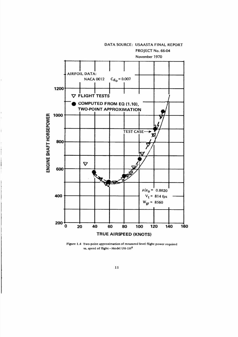
A test case is shown in Fig. 1.4, where actual flight test data s for the UH-1H helicopter flown at Wg r =
8560 lb and air density p = 0.00205 was used as inputs for (V e = 64 kn, SHP = 500 hp) and (V e = 128
kn, SHP = I000 hp), while for the other unknowns the following values were assumed: Boa = 0.89 and
hindf = 1.12.
Introducing the above values into Eq (1.10), a set of two linear equations in wfp and ('_d/_) was ob-
tained, whose solution yielded Wfp = 282.5 psf (f = 30.3 ft 2) and (_-d/Q) = 1/57. When the above values
were reintroduced into Eq (1.10) along with the previously assumed rloa and hindf values; (SHP/Wg r)
and then SHP = (SHP/Wgr)Wg r were calculated for several flying speeds, thus resulting in a perfect fit of
the test points (see Fig. 1.4).
Once all the unknowns in Eq (1.10) are either found, or assumed, it is possible to use that equation
for determining, with some confidence, the (SHP/Wg r) = f(V) curves of the compared helicopters at the
specified gross weights (say, maximum flying) and altitude (SL, ISA). It should be recalled at this point
that when dealing with different gross weights, new values of Wfp should be used: Wfp = Wfpo(Wgr/Wgro).
As an example of this procedure, the (SHP/Wg r) = f(V) curve was recomputed for the UH-1H heli-
copter at Wgr = 9500 lb and SL, ISA, and the so-obtained figures compared with those obtained from the
generalized flight test data presented in Fig 67 of Ref. 6. It can be seen from Fig. 1.5 that the above-
described method of recalculating the (SHP/Wor) = f(V) values for other gross weights and altitudes appears
to be quite satisfactory.
In the reconstruction of the (SHP/Wg r) = f(V) relationship from published performance data by the
two-equation method, the coordinates of the high speed point (Vmax,SHP) or (Vcr.max,SHP)should
usually be directly given. But as far as the other point (Ve,StlPmi n) is concerned, neither the speed nor the
power coordinate is directly available.
The (SHPmin/Wg r) values can be estimated from the usually published maximum rate of climb
(VCf)rnax at SL, ISA and the generally accepted convention that (R/C)ma x is related to the known maximum
continuous power setting (SHPmax.co n t ), or transmission limit.
Assuming that the so-called climb efficiency factor (hpc) (see Sect. 5, Ch. Ill, Ref. 7) can be taken as
hpc = 0.85, and (Vcf)ma x is in fpm, the (SHPmin/Wor) can be expressed as follows:
(SHPmin/Wgr) = (SHPmax.cont/Wgr) -- [(Vcf)ma×/33,000#pc ] (1.11)
10
8/3/2019 Stepi Soviet 1
http://slidepdf.com/reader/full/stepi-soviet-1 21/298
120(]
m 1000w
0
w¢/3
0
z 80(]
<
z
Z 60Ow
400
IAIRFOIL DATA:
NACA 0012
I
DATA SOURCE: USAASTA FINAL REPORT
PROJECT No. 66-04
November 1970
m
Cdo= 0.007
V FLIGHT TESTS t
mQ COMPUTED FROM EQ (1.10), /
TWO-POINT APPROXIMATION
TEST CASE
7/v
P/Po = 0.8620
Vt: 814 fps
Wgr : 8560
2000 20 40 60 80 100 120 140
TRUE AIRSPEED (KNOTS)
Figure 1.4 Two-point approximation of measured level flight power required
vs. speed of flight-Model UH-1H s
160
11

8/3/2019 Stepi Soviet 1
http://slidepdf.com/reader/full/stepi-soviet-1 22/298
0.12
" 0.10
I
U-
0
a 0.08Z
O¢1.
tr-ILlO-
o. 0.06"1-
0.0_-
\
0
0
\
\\
\
\
COMPUTED FROM DATA IN FIG. 1.4 USING EQ. (1.10)
BASED ON FIG. 67, REF. 6
\
\
/
UH-1H, Wgr = 9500 LB SL, ISA /
\
\ /
/
• " ' Jo ' £ "
SPEED OF FLIGHT, KN
P/
/
2
|
120
Figure 1.5 Comparison of (SHP/Wg r) = f(V) deduced from flight tests at higher altitude
and lower gross weight with flight test data for Wg r = 9500 and SL, ISA.
From Eq <1.11) the ordinate of the [Ve, (SHPmin/Wgr)] point can be obtained, but the abscissa
(V e) is still missing. However, this situation can be remedied through the so-called first approximation
approach, based on the single high speed point, say [Vmax, (SHPmax.cont/Wor)]. In this case, in Eq (1.10)
kvf , kindf, _oa and (_d/E_) values are all assumed, and the equation is solved for Wfp only.
Differentiating Eq (1.10) with respect to V, while assuming that the last term in that equation is
constant, and equating the result to zero, one finds that an approximate value of the speed Ve corre-
sponding to (SHPmin/Wg r) can be obtained in knots as:
Ve = 0.448"_/'k2v kindWWfp/p 2' (1.12)
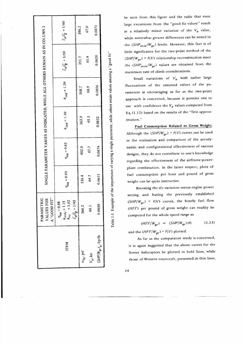
Figure 1.6 and Table 1.1 was prepared in order to find to what extent the variation in the assumed
levf, kindr Boa and "(d/'dZ values would affect the Ve value. Here, the (SHP/Wor) = f(V) curve, based on
manufacturer's data 8 was reasonably approximated by assuming that rloa = 0.88, kindf = 1.15, kv¢ = 1.02
and (_d/_£)= 1/45 (Fig. 1.6). Then the influence of a single parameter variation was investigated (Table
1.1) and then all the parameters were taken at either their maximum or minimum values (Fig. 1.6). It can
12

8/3/2019 Stepi Soviet 1
http://slidepdf.com/reader/full/stepi-soviet-1 23/298
SHAFT HORSEPOWER PER LB OF GROSS WEIGHT
VS SPEED OF FLIGHT
SA-365N, SL, ISA, GW = 7055 LB
ASSUMED
f/oa = 0.88; kindf = 1.IS; "Ca/_ = 1/45
_7oa = 0.93; kindf = 1. I0," "_diE_ = llSO
11oa = 0.83; hindf = 1.20; 3dl_ = II40
COMPUTED FROM EO (1.10)
wfp = 366.2 psf
wfp = 322.2 psf
wfp = 429.3 psf
0.14
0.12
0"101 .
| i
SPEED OF FLIGHT, KN
Figure 1.6 Example of approximating a given (SHP/VVg) = #(V) curve through the single-point approach
and various assumed values of noa; kin d and _d/_
13
8/3/2019 Stepi Soviet 1
http://slidepdf.com/reader/full/stepi-soviet-1 24/298
eq
z
,d©
Z
<Z
<z_
.-r[-©
<
<
Ez
<
r_
<>
r_
<a.
Z
o
II
o
Ll
o
H
o
El
o
ii
o
ii
H U H H
o
o
_q
o
o
qo
><
r_
"i
oo
c
>
4.1
J
E
._,
>
o
be seen from this figure and the table that even
large excursions from the "good fit values" result
in a relatively minor variation of the Ve value,
while somewhat greater differences can be noted in
the (SHPmin/Wg r) levels. However, this fact is of
little significance for the two-point method of the
(SHP/Wgr) = f(V) relationship reconstruction since
the (SHPmin/Wor) values are obtained from the
maximum rate of climb considerations.
Small variations of V e with rather large
fluctuations of the assumed values of the pa-
rameters is encouraging as far as the two-point
approach is concerned, because it permits one to
use with confidence the V e values computed from
Eq (1.12) based on the results of the "first approx-
imation."
Fuel Consumption Related to Gross Weight.
Although the (SHP/Wor) = f(V) curves can be used
in the evaluation and comparison of the aerody-
namic and configurational effectiveness of various
designs, they do not contribute to one's knowledge
regarding the effectiveness of the airframe-power-
plant combination. In the latter respect, plots of
fuel consumption per hour and pound of gross
weight can be quite instructive.
Knowing the sfc variation versus engine power
setting and having the previously established
(SHP/Wor) = f(V) curves, the hourly fuel flow
(HFF) per pound of gross weight can readily be
computed for the whole speed range as
(HFF/Wgr) = (SHP/Wor)Sfc (1.13)
and the (HFF/Wor) = f(V) plotted.
As far as the comparative study is concerned,
it is again suggested that the above curves for the
Soviet helicopters be plotted in bold lines, while
those of Western rotorcraft, presented in thin lines,
14

8/3/2019 Stepi Soviet 1
http://slidepdf.com/reader/full/stepi-soviet-1 25/298
SPEED OF FLIGHT, KN
Figure 1.7 Scheme for comparing hourly fuel consumption.
would form the background (Fig. 1.7). As in the preceding case, this comparison is also limited to the
SL/ISA condit ions.
An auxiliary grid of straight lines expressing various constant values of fuel consumed per pound of
gross weight and say, 100 n.mi, would permit one to judge at a glance those values for various machines.
However, in order to provide a means for a more precise comparison of the FF = (HFF/WgrV)IO0 levels
for the compared helicopters, separate plots of FF = f(V) are provided (Fig. 1.8).
zz
ts
tw
Q._Z
wO
ii
illlll I m e
SOVIET
WESTERN
J
SPEED OF FLIGHT, KN
Figure t.8 Scheme for comparing fuel required per lb of gross weight
and 100 n.mi of Soviet and Western Helicopters
15

8/3/2019 Stepi Soviet 1
http://slidepdf.com/reader/full/stepi-soviet-1 26/298
Fuel Consumption Related to Payload. The fuel utilization aspects discussed in the preceding sub-
section still fail to serve as a criterion for a comparison of design effectiveness with respect to the aerody-
namics-configuration-powerplant-weights design combination. In order to obtain tools for a more complete
design comparison, both hourly fuel flow and fuel required per 100 n.mi and one pound of the zero-range
(time) payload can be used. Graphs reflecting these values (plotted vs speed of flight) can be readily obtained
by dividing the data shown in Figs. 1.7 and 1.8 by the (Wp/)e=O/Wg r ratio; where the zero range (_) payload
(Wp/)_= 0 :- (Wp/)t= 0 is as defined by Eq (1.3).
However, it is more interesting to see how the fuel weight to payload ratio would vary with the dis-
tance flown. Strictly for comparative purposes, this can be done as follows:
Defining payload at zero range as (Wpl)o; the payload for distance £ (neglecting reserves and fuel for
takeoff and maneuvers) can be expressed as
(wp_)_ = (win) o - (Wfu)_
where (Wfu)1 is the weight of fuel required for distance _.
Dividing both sides of the above equation by (Wpl); and rearranging, one obtains
(Wf_)_ (Wot )o- 1
(Wpl)_ (Wpl)2 _ (1.14)
Further assuming that for short distances, the hourly fuel flow at a given speed remains constant,
HFF _ const; the (Wpl)o can be expressed as follows:
(Wpt)Q = (WoD o -- (HFF/V)_
and Eq (1.14) can be rewritten as
(Wfu )e
(wo,)e
(wpl)o= -- I (1.14a)
(Wp/) ° -- (HFF/V)fZ
Dividing the numerator and denominator of the first term on the right side of Eq (1.14a) by (Wpt) o,
one obtains
(Wfu)_ I- - I (1.15)
(Wpl)£ ] 100 HFF f_
(WOt)oV 100
In analogy to the FF quantity discussed in the preceding subsection, I00 HFF/(Wol) o V can be called
the relative fuel consumption per one pound of the zero-range payload and one hundred nautical miles,
and designated by the symbol (FFpl)o, Eq (1.14) can now be written as
16

8/3/2019 Stepi Soviet 1
http://slidepdf.com/reader/full/stepi-soviet-1 27/298
= 1
(wpl)e 1 - (_1)o_11oo-1 (1.16)
Using the optimal values of the (FFpl)o quantity (which is readily obtainable as (FFpl)oop t =
(_-f)optl[(W_)olWg,lromgraphssuchasthatin Fig.1.8for thecomparedelicopters),graphshowing
the (Wfu) l /(Wpl)g = f(_) relationship can be prepared for the Soviet and Western helicopters (see Fig. 1.9).
azD0 m
O.
uJ
m 0
5¢0,,, <
U-
SOVIET
WESTERN
FLIGHT DISTANCE, N.MI
Figure 1.9 Comparison of Soviet vs Western fuel weight-to-payload ratios, shown as a function of flight distance.
Using the presently described methods for forward flight, plus those discussed in subsection 1.4 for
the hovering case, the important energy aspects of Soviet and Western helicopters can be examined and
compared.
Productivity Index_ PI. In a comparative evaluation of various helicopters it is of importance to know
not only the cost in fuel at which a unit weight of payload can be delivered over a given distance, but
also how fast this task can be accomplished. To establish some yardstick in that respect, the notion of the
productivity index (PI)t is introduced by defining that quantity as follows:
(PI)j = [(Wpl)g/We ] V (1.17)
where (Wpl) _ is the maximum theoretical payload corresponding to flight distance 2, V is the speed of
flight in knots, and W e is the weight empty (in the same units as Wpl).
But
w_ = (w_)° - _(_/mo)%,
17

8/3/2019 Stepi Soviet 1
http://slidepdf.com/reader/full/stepi-soviet-1 28/298
and Eq (1.17) can be rewritten as follows:
(PI)I " = {[(Wpl)o/Wgrl -- (_t21100)_ Vl(We/Wg r) (1.17a)
where FF is (as before) the fuel required per pound of gross weight and 100 nautical miles, and distance
is in nautical miles.
Using Eq (1.17a), the (PI)I values are computed first for the compared helicopters for several flight
distances (say, O, 100, 2O0, and 300 n.mi) and then, the whole range of speeds from 0 to Vma x. The
result of this phase can be graphically presented as in Fig. 1.10.
xa 2=0 x
Z -/ Z
O.O.
_,_ _
SPEED OF FLIGHT, KN
SOVIET
WESTE_j ''_
SPEED OF FLIGHT, KN
Figure 1.10 Proposed scheme for comparing productivity index vs speed for selected flight distances
of Soviet and Western helicopters.
Now the maximal values of the productivity index corresponding to various selected flight distances
can be plotted vs distance as schematically indicated in Fig. 1.11.
e_
<
FLIGHT DISTANCE, N.MI
Figure 1.11 Maximal productivity index values vs distance scheme for Soviet and Western helicopters.
18
8/3/2019 Stepi Soviet 1
http://slidepdf.com/reader/full/stepi-soviet-1 29/298
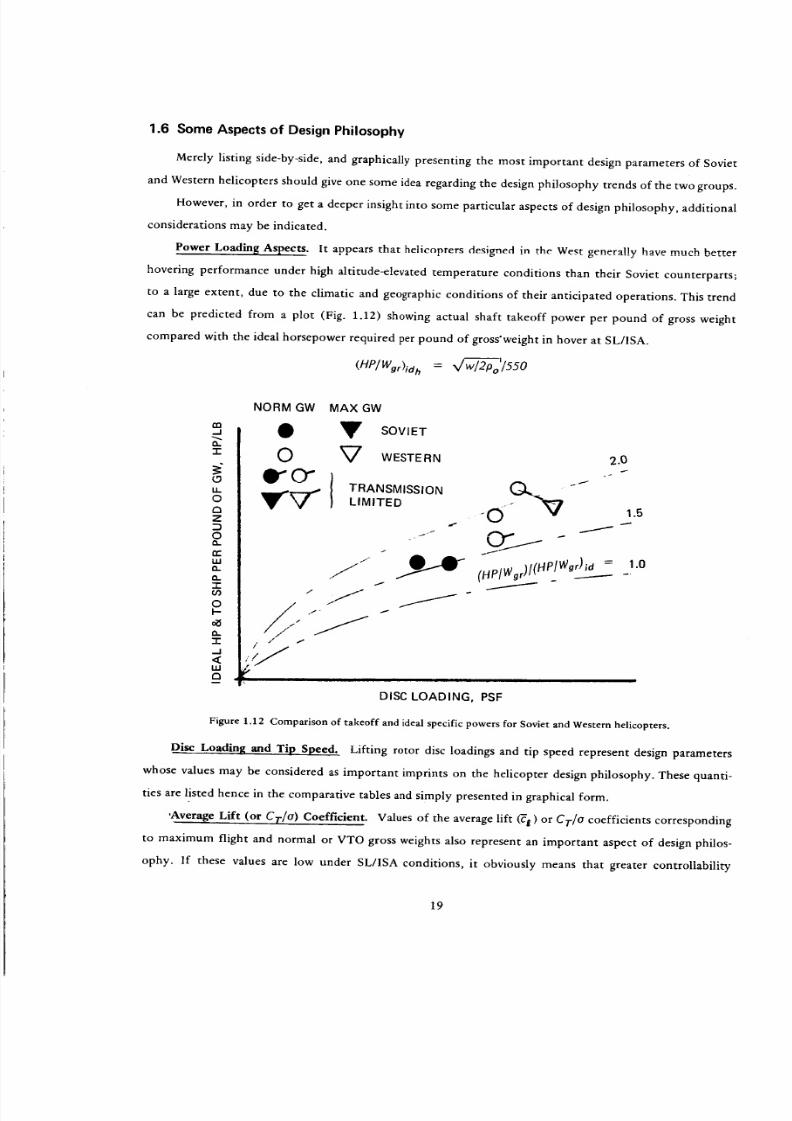
1.6 Some Aspects of Design Philosophy
Merely listing side-by-side, and graphically presenting the most important design parameters of Soviet
and Western helicopters should give one some idea regarding the design philosophy trends of the two groups.
However, in order to get a deeper insight into some particular aspects of design philosophy, additional
considerations may be indicated.
Power Loading Aspects. It appears that helicopters designed in the West generally have much better
hovering performance under high altitude-elevated temperature conditions than their Soviet counterparts;
to a large extent, due to the climatic and geographic conditions of their anticipated operations. This trend
can be predicted from a plot (Fig. 1.12) showing actual shaft takeoff power per pound of gross weight
compared with the ideal horsepower required per pound of gross'weight in hover at SL/1SA.
(HP/Wgr)id = X/_o/SSO
flo.J
t,,"1-
(.9LL
o13z
o
n,"
a.
"1"
oI-
"1"
_1<uJ
13I
NORM GW
O
OgrO"
MAX GW
y SOVIET
V WESTERN
TRANSMISSION
LIMITED
j.-
J
i/"
, / t
,,
2.0
DISC LOADING, PSF
Figure 1.12 Comparison of takeoff and ideal specific powers for Soviet and Western helicopters.
Disc Loading and Tip Speed. Lifting rotor disc loadings and tip speed represent design parameters
whose values may be considered as important imprints on the helicopter design philosophy. These quanti-
ties are listed hence in the comparative tables and simply presented in graphical form.
'Average Lift (or CT/O) Coefficient. Values of the average lift _e) or CF/O coefficients corresponding
to maximum flight and normal or VTO gross weights also represent an important aspect of design philos-
ophy. If these values are low under SL/ISA conditions, it obviously means that greater controllability
19

8/3/2019 Stepi Soviet 1
http://slidepdf.com/reader/full/stepi-soviet-1 30/298
(maneuverability) margins would be available for operations under high altitude and/or ambient tempera-
ture conditions. Also blade stall aspects at higher flying speeds and altitudes would be more favorable.
However, on the other hand, low _ (CT/O) values could lead to less favorable (-Cd/_) ratios; thus resulting
in higher profile power levels. This aspect may be especially important for hovering capabilities of rotor-
craft with low ratios of the takeoff specific power to its ideal value.
For comparative purposes, the average lift coefficient in hovering will be defined here as
_._ = 6Cr/a = 6kvw/aPo Vt2
where #v is the download factor.
Using two scales, the magnitudes of both _ and CT/o will be presented for the Soviet and Western
helicopters in the manner shown in Fig. 1.13.
}-u___.-J zUJ UJ
t-_ c9
5,Tnn U-
LU
_o
<
Q'B
(9" O"NGW MAX. GW
_I V SOVIET
0 V WESTERN
DISC LOADING, PSF
Figure 1.13 A scheme for comparingE t and CT/a of Soviet and Western helicopters.
Producibility and Maintainability. Producibility and maintainability, including some indications
regarding the skill-level of servicing and manufacturing personnel, definitely represent two important
aspects of helicopter design philosophy. It would be hence desirable for the compared helicopters to pro-
vide either actual statistical figures in this respect or, at least, operational-handbook or sales-brochure
projections. Unfortunately, with very few exceptions, this type of information is not available on the
Soviet rotorcraft. Consequently, it became necessary to limit the main considerations of this subject to
a general discussion (which will be conducted in Part II) of such trends and goals as, for instance, those
presented in Tishchenko's work, while limiting actual quantitative comparisons to those few cases wherein
the necessary data is available.
1.7 Configurational Aspects
There are many configurational aspects wherein comparison may be important in assessing common-
alities and differences of Soviet vs Western design philosophies. Obviously, one of them is the selection of
20

8/3/2019 Stepi Soviet 1
http://slidepdf.com/reader/full/stepi-soviet-1 31/298
theoverallhelicopteronfigurationsingle-rotor,andem,oaxial,ndside-by-side).owever,hisaspect
will be thoroughly considered in Part III of this study. Consequently, in this part, attention will be called
only to some configurational topics of the single-rotor scheme, especially those which affect aircraft per-
formance. Thelocation of the tail rotor and management of the main-rotor torque compensation, with
emphasis on minimization of the tail-rotor power/main-rotor power ratio through the proper selection
of the related design parameters, can be cited as one such topic.
As shown in Fig. 1.14, the location of the tail rotor can be defined by two coordinates (x and y)
whose values should be registered in absolute as well as relative (_ = x/R), (if=y/R) forms.
Figure 1.14 Tail rotor Coordinates.
With respect to the main-rotor torque compensation aspects, it would be of interest to indicate which
design parameters have the most important influence on the tail-rotor to main-rotor power ratio; as well
as to establish a simple method for finding numerical values of that ratio, since it may be needed for per-
formance comparisons. To achieve this goal, the following approximate relationships are developed.
Ratio of Tail-Rotor (RPtr) ' to Main-Rotor (RPrn r) Powers in Hover at SL/ISA. The tail-rotor thrust
in pounds (Trr) required to compensate the main-rotor torque can be expressed as follows:
Trr = (RPmr/Vrrnr)(Rrnr/Xtr) (1.18)
or denoting x tr/Rmr = "Xtr,
Ttr = RPmr/Vtmr_'tr (X.lSa)
where Vtrnr and Rmr, respectively, are the tip speed (fps), and radius (ft) of the main rotor, and Xtr
is the distance of the tail rotor center from the main-rotor shaft axis (ft), while RPrn r is in ft -lb/sec .
21

8/3/2019 Stepi Soviet 1
http://slidepdf.com/reader/full/stepi-soviet-1 32/298
Thepowerequiredby thetail rotorof the open-airscrew type at SL/ISA can, in turn, be written
(ft-lb/sec) as:
3/2 2 vRPtr = (Ttr /_trPo FMtr)kblo (1.19)
where Rtr is the tail-rotor radius (ft), FMtr is the tail-rotor figure of merit and kbl o is a coefficient account-
ing for the blocking effect of the structure on which the tail rotor is mounted.
For the Fenestron - assuming that there is no contraction of the slipstream,
3(2
(RPtr) F = ,½Ttr /_ FMtr (1.19a)
In turn, RPmr appearing in Eq (1.18) can De presented as follows:
where hVh is the helicopter download factor in hover; Wor is the helicopter gross weight; and FMmr is the
main-rotor figure of merit.
Substituting Eq (1.20) into Eq (1.18a) and the latter, in turn, into Eqs (1.19) and (1.19a), the follow-
expressions for the RP of the open-airscrew tail rotor is obtained:
RPtr = (lev3h̀ z WgrX/Wmrl2Po'll/tm r FMmr Err) 3,2 kblol_ FMtr (1.21)
and for the Fenestrone-type
t 312 3/2 .]"'-'_'_
(RPtr)F = ½(kVh Wgr_/Vtrnr FMmr Xtr) /x/TrRtrP o FMtr (1.21a)
Writing Wgr/rrR2mr instead of Wmr in Eq (1.20) and then dividing Eq (1.21) and (1.21a) by the so-
modified Eq (1.20), the sought power ratio for the open airscrew becomes
= - 3/2 k (_/Vtm r _ 3/2RPtr/RPmr) hVh blo tr) (Rrnr/Rtr)/FMtrX/FMmr (1.22)
and for the ducted one,
= 3/2
(RPtr/RPrnr)F (kvh_/Vtmr Xtr) (0. 707Rmr/Rtr)/FMtr _ (1.22a)
It can be seen from Eqs (1.22) and (1.22a) that the most important parameters influencing the
(RPtr/RPmr) values are: the ratio of the ideal induced velocity at the main rotor disc to its tip speed
and the ratio of the tail-rotor distance to the main-rotor radius (Xtr), as both these quantities appear to
the 3/2 power; next in importance are the main-to-tail-rotor radii and the tail-rotor figure of merit (both to
the first power). Of lesser significance is the main-rotor figure of merit as it appears to the 1/2 power.
One can see hence that in comparing design philosophies of various helicopters, it may be of interest to
22

8/3/2019 Stepi Soviet 1
http://slidepdf.com/reader/full/stepi-soviet-1 33/298
presentuchconfigurational aspects as the (_tr/Rrnr) and (Rmr/Rtr) ratios as well as to indicate the
(ViOmr/Vtrnr) values, where Viclrnr is the ideal induced vdocity of the main rotor.
This can be done in tabular, as well as graphical form.
The (_'tr/Rmr); (Rtr/Rmr) and (Viamr/Vtm r) ratios can readily be computed from data usually
available in the published material on various helicopters. However, in order to complete the calculations
indicated by Eqs (1.22) and (1.22a), the values of FMmr and FMtr are required. They can be assumed, or
still better, approximated in the manner described below.
Estimate of Rotor FM = RPid/RP. There are available results of many tower and/or stand tests
giving a relationship between rotor thrust T (lb) and rotor power RP (ft-lb/sec) for full-scale lifting and
tail rotors: RP = [(T) or Cp = £(C 7) under static conditions OGE.
Rotor thrust can be expressed in terms of the average blade lift coefficient _,
T = (I/6)oTrR2pVr 2_ (1.23)
while the rotor power can be given in terms of the total blade drag coefficient (_D):
RP = (I/8)olrR2 pVt 3 E D (1.24)
With respect to the ideal rotor power, it can be expressed as a function of the blade average lift coeffi-
cient and rotor solidity ratio. Remembering that
Rpi , =
and substituting it into the above equation (1.23) for T, and simplifying, one obtains
RPia = O.048(c;-_ )3/2nR2 p Vt 3 (1.25)
Dividing Eq (1.25) by Eq (1.24), the expression for the figure of merit becomes:
Fm = 0.385X/_(_ 3/21Co) (1.26)
From available test-established RP = f(T) or Cp = f(C T) relationships at various blade tip Mach
numbers, blade airfoil sections, and blade Reynolds numbers, FM = f('c2 ) curves can be drawn for the
given rotor solidities. For instance at o = 0.0996, at which tower tests of the UH-61A rotor were per-
formed (Fig. 1.16). The question is how to transfer the available results to other solidities.
The influence of various rotor solidity ratio values can be accounted for by assuming that for a given
type of rotor (similar blade Reynolds and Mach numbers, airfoils, twist, and planform distribution) at any
given E value, the difference between the actual and ideal total drag coefficients remains constant:
ACol_l=eonst = CD -- C--Did = const
23

8/3/2019 Stepi Soviet 1
http://slidepdf.com/reader/full/stepi-soviet-1 34/298
I-
EI.,I.I
Ii
OLI.I
eI.-
D{.9
I1.
0.7
0.6
0.5'
0.4
0.3
0.2
0.1
Oo = 0.0996 _-'-_i "
COMPUTED FOR
02 = 0.0734
......... 'j f_'"' ' ............. 't .... .... '
:::-:-iT ": ': 7: - :J ¢;_dl_*_"t , t" +.7*TI:*.*: " ,?* ;T'_rI. 'TrT-:-_-tt-t:'-:t;-:tTt:TT." t
:i _: __'_ ;i!:l?: _t :_.: ',1_?'_':ii,tZit!:i:i:?i: 1
. , , ] , ] _ , , ] t ] _ , ? i i _ _ t ; r ; ; , , i , , . . ; h _ , i _ * ! , I p , t , d t _ ,
'.11_ ! .: I::'11;;: I:. ';'.;. I.. 'i '11.1.11:';1: ::'.::I;.'.._ :':, II ...... _..... _.... , .......
, , _1' " '! / . ' :, ;: _i ; ! :: ,." ' ' i_; :
.,,. ..... [ .......... _4- + _+ ' -_ .,_, .T_* ,-++. t _-+-, .
........... t .. .I .... f . t . I t, _
:El:: D, N ! r : . t: ! I t#' ,:;:_l, ,_ _.H[_i, It,, ',t l_, I '.l , l J|Ll.,i_I l',lll,;q I
........... " ...... "-"_ ' *_ " "_ 'i" _-_'_, _+-_ + ........"+- +_ _ 7'_ '- _,* r
0 0.1 0.2 0.3 0.4 0.5 0.6 0.7 0.8
AVERAGE BLADE LIFT COEFFICIENT, _'I_
Figure 1.16 Example of the FM = f(El) rela tionships at various rotor solidities.
In turn, making FM = ] in Eq (1.26), CDi d can be expressed as follows:
C--Did = O.385-_t 3,2 X/r_
Assigning o subscripts to the available _O = f(_ ) relationships, and 1, 2, 3 .... to those representing
different o values, the total drag coefficient at this new; say, o_ value, but with the same _, can be written
as
_0, = "CDid, + A_O = 0.385g_anx/-d_ + CD o --0.385_'/_X/'_o
Substituting the above into Eq (1.26), the following is obtained:
0.385"_ 3_FM 1 =
coo + - V o)
Dividing the numerator and denominator of the above equation by C'--D, while multiplying by _/-_o,
the figure of merit for a new rotor solidity ratio value (o_) can be expressed as
24
8/3/2019 Stepi Soviet 1
http://slidepdf.com/reader/full/stepi-soviet-1 35/298
FM oFMI = (1.26a)
O_o/O_(1 -- FM o ) + FM o
Determination of Overall Rotor-Power Transmission Efficiency. Once the approximate values of the
(RPtr/RPmr) ratio are computed by the above described methods, then the overall rotor-power trans-
mission eff iciency factor (r?oa -= RHP/SHP = RP/SP) in hover can be determined with some confidence as
rtoa = _Xmtot/[ I + (RPtr/RPmr)] (1.27)
where rlxmtot is the total mechanical transmission efficiency accounting for the actual transmission
(gear) losses and power utilized for runiaing the accessories, and rlxmto t = 0.96 would represent a good
average value.
Determination of the Overall Figure of Merit. Knowing r/oa, hVh, and FMmr the overall figure of merit
can be computed as
FMoa = 1?oaFM m r/kvh/2
and the so-obtained values may be used for checking those resulting from the OGE hovering data, as pre-
viously described in Section 1.
Ratio of Tail--Rotor to Main-Rotor Power in Forward Flight at SL/ISA. Assuming that the tail-
rotor hub and attachment drag is accounted for in the estimates of the whole helicopter flat plate area
(f) and there is no "help" in the main-rotor torque compensation in forward flight from a fixed vertical
empennage; the rotor power of the tail rotor in that regime of flight at SL/ISA becomes
r Tt, 3 (, + 4.Z_%,)(Z_/ae),,,,,]r (1.28)
while Ttr is given by Eq (1.18a) as in hovering and V and Vtt r are both in fps.
Substituting the right-hand side of Eq (1.18a) for Ttr in Eq (1.28), the following expression for the
power ratio is obtained:
e__,, _ = [2 Rpm,e,.r/, _R_rpov v,_, z,,3(i4 (1.29)
Further assuming that Vtm r = Vtt r = Vt and hence Idtr =//, Eq (1.29) becomes
RPtr [ RPm r, = vt3), t. -- I + 4. 71a24 tr
(1.29a)
25

8/3/2019 Stepi Soviet 1
http://slidepdf.com/reader/full/stepi-soviet-1 36/298
It shouldbenotedthattheexpressionn theparenthesesn thedenominatorf thefirsttermof
Eq(1.29a)epresentshypotheticalowerwhichemainsonstantorunvaryingand V r-
In order to get some idea regarding the magnitude of the tail-rotor power losses in forward flight,
the values of the (RPrr/RPmr) t ratio may be calculated at Ve corresponding to 5HPmi n and Vcrrnax
(Vma x) achievable at the maximum continuous engine power setting.
Once the _?oa values in forward flight are estimated, they may be used in the (SHP/Wor) = f(V) de-
termination.
The actual procedure is facilitated by the fact that SHP corresponding to Vcrrnax is usually directly
available, hence by using the assumed _?oa values, the approximate RPmr can be readily calculated as
RPmr = 550 SHPma x conrrloa
and substituted into Eq (1.29a).
Having the so-refined (RPtr/RPmr) i values, Tloa in forward flight can be computed from Eq (1.27).
Cabin Volume and Cabin Floor Area Loading. With respect to configurational aspects of design
philosophy, it may be of interest to look into such aspects as volume and floor area of the cargo/passenger
cabin. In order to permit one to investigate these aspects on a common basis, it is suggested to graphically
present figures regarding (Wpl)o/Vca b and (Wo/)o/Scab where (Wpl) ° corresponds to the maximum flying
weight; Vca b is the cabin volume in cu.ft; and Sca b is the cabin floor area in sq.ft.
1.8 Concluding Remarks
The introductory considerations presented in this chapter provided an outline for various aspects
of the general comparison of the Soviet vs Western helicopters. Various design parameters and perfor-
mance items were singled out as special entities facilitating a quantitative comparison of the two design
philosophies. This, in turn, led to the identification of basic data necessary for that procedure. Conse-
quently, for each of the considered gross-weight classes, tables of principal characteristics and performance
were constructed in such a way as to include all the necessary information (see Table 1.2).
26

8/3/2019 Stepi Soviet 1
http://slidepdf.com/reader/full/stepi-soviet-1 37/298
Z
[,,.el)
r_
z
[.-
z
t _4
ZZ
,,,J
_ Z
• _ _
_ ,-1 m
e_
Z
_u b,
;>©
©
z0
r_
Z,0
zo_ r-.
27
0 _ ..a o
uO
Z
o
Z
z _.,,
8/3/2019 Stepi Soviet 1
http://slidepdf.com/reader/full/stepi-soviet-1 38/298
]
Z
,- _ " _.
Z
28
0
°
o
ee
8/3/2019 Stepi Soviet 1
http://slidepdf.com/reader/full/stepi-soviet-1 39/298
Chapter 2
Powerplants
2.1 Introduction
A comprehensive comparison of the state of the art of the Soviet helicopter powerplants with those
of the West is outside the present study. However, there are some engine characteristics about which
some approximate knowledge is required in order to perform the general comparison of the two helicopter
technologies as outlined in the preceding chapter.
The two most important engine characteristics for that comparison are (1) variation of the sfc with
partial power setting, and (2) power lapse rate with altitude and temperature. Both these characteristics
are usually not available for Soviet engines and for some Western engines as well. Consequently, a method-
ology had to be developed for even approximate estimates of these two items.
Engine power ratings are also important, but usually they can be directly found in published litera-
ture.
Although, as mentioned above, this study is not directed toward comparison of engine technologies,
there are some additional readily-available powerplant characteristics about which some knowledge may
be of interest to the rotorcraft designer, and whose comparative presentation may shed some light on the
engine state of the art of the two groups. Two such items may be (1) engine specific weight (Weng/SHPTo)
and (2) compactness, which may be defined as SHPTo/(length × width X height).
Similar to the proceedings discussed in the preceding chapter, all engines are also grouped according
to their application to the helicopters belonging to the four gross weight classes. Consequently the
following groups of engines are considered.
1. Engines installed in the up to 12,000-1b gross weight helicopters.
Soviet
(1) lsotov/PZL GTD-350
(2) Vedeneev M-14V-26 (reciprocating)
Western
(1) Allison 250-C20B
(2) Allison 250-C30
(3) Turbomeca Arriel 1C
(4) Lycoming T53-L-13
(5) Lycoming LTS 101-650C-2
29

8/3/2019 Stepi Soviet 1
http://slidepdf.com/reader/full/stepi-soviet-1 40/298
2. Engines installed in 12,000 to 30,O00-1b gross weight helicopters
Soviet
(1) lsotov TV-2-117A
(2) Glushenkov GTD-3F - Similar to TVD-10
Western
(1) Turbomeca Turmo 1VC & Makila 1.A (3) General Electric T58-GE-16
(2) General Electric T58-GE-5 (4) General Electric T700-GE-700
3. Engines installed in 30,000 to 100,000-1b gross weight helicopters
Soviet
(1) Soloviev D-25V (TV-2BM)
(2) Hypothetical
Western
(1) Lycoming T55-L-712
(2) General Electric T64-GE-415
(3) General Electric T64-GE-413
4. Engines installed in the over 100,000-1b gross weight helicopters
Soviet
(1) Soloviev D-25VF
(2) Hypothetical
Western
(1) Allison T701
Tables of the principal engine characteristics were prepared for each of the above groups (for ex-
ample, see Table 2.1). Graphs of sfc variation with partial power setting, power lapse rate vs lSA altitude,
specific weights, and TO power to the overall volume ratio are presented separately.
2.2 Auxiliary Relationships
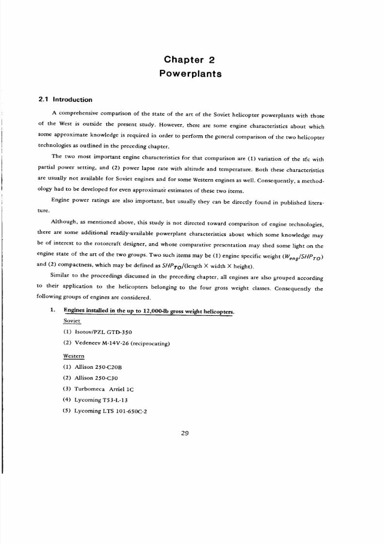
Estimates of sfc Variation vs Partial Power Setting. Even in the case of rather incomplete infor-
mation on engine characteristics where values of sfc are given at two SHP levels only, a relationship of
sfc = f(SHP/SHPTo) can be establ ished.
Assuming that the engine fuel flow is linear with SHP, and at least two points of (sfc, SHP) are given
(one of them being for the takeoff power setting), a relationship between (FF/FFTo) -- f(SHP/SHPTo),
30
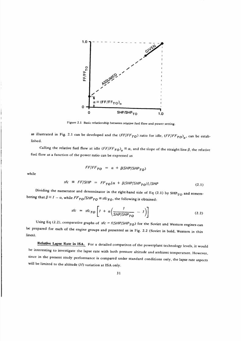
8/3/2019 Stepi Soviet 1
http://slidepdf.com/reader/full/stepi-soviet-1 41/298
1.0
oI-
it
itkk
f
f¢¢
/
_ (FF/FFTo) o¼
/
---y//
J
!
0 SHP/SHPTo 1.0
Figure 2.1 Basic relationship between relative fuel flow and power setting.
as illustrated in Fig. 2.1 can be developed and the (FF/FFTo) ratio for idle, (FF/FFTo) o, can be estab-
lished.
Calling the relative fuel flow at idle (FF/FFTo) o = _, and the slope of the straight line/3, the relative
fuel flow as a function of the power ratio can be expressed as
FF/FFTo = a + [3(SHP/SHPTo)
while
sfc = FF/SHP = FFTO[a + IJ(SHP/SHPTo)]/SHP (2.1)
Dividing the numerator and denominator in the right-hand side of Eq (2.1) by SHPTo and remem-
bering that t3 = I - t_, while FFTo/SHPTo = sfcTo , the following is obtained:
sfc = sfcro [I + c_ ISHP/SHPTo 1)] (2.2)
Using Eq (2.2), comparative graphs of sfc --- f(SHP/SHPTo) for the Soviet and Western engines can
be prepared for each of the engine groups and presented as in Fig. 2.2 (Soviet in bold, Western in thin
lines).
Relative Lapse Rate in ISA. For a detailed comparison of the powerplant technology levels, it would
be interesting to investigate the lapse rate with both pressure altitude and ambient temperature. However,
since in the present study performance is compared under standard conditions only, the lapse rate aspects
will be limited to the altitude (H) variation at ISA only.
31
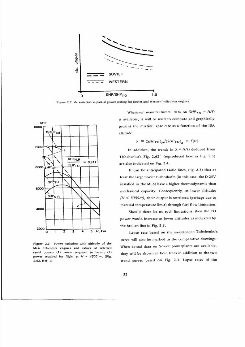
8/3/2019 Stepi Soviet 1
http://slidepdf.com/reader/full/stepi-soviet-1 42/298
,_....... SOVIET
WESTERN
'11
0 SHP/SHPTo 1.0
Figure 2.2 sfc variation vs partial power setting for Soviet and Western helicopter engines.
SHP
8000 1
I_..SHP're f\!
1
\
_SHP ref
s_ _ "
,°°° ISH_PN.R
40OO
SHPN oR
=0.917
, SHPTo
\
2- .",,,\
3000
0 1 2 3 4 5 H, km
Figure 2.3 Power variation with altitude of the
Mi-6 helicopter engines and values of referred
rated power: (1) power required in hover; (2)
power required for flight at H = 4500 m. (Fig.
2.62, Ref. 1).
Whenever manufacturers' data on SHPTo = f(H)
is available, it will be used to compute and graphically
present the relative lapse rate as a function of the ISA
altitude
_, =-- (SHPTo)H/(SHPTO)o = f(H)
In addition, the trends in X = f(H) deduced from
Tishchenko's Fig. 2.621 (reproduced here as Fig. 2.3)
are also indicated on Fig. 2.4.
It can be anticipated (solid lines, Fig. 2.3) that at
least the large Soviet turboshafts (in this case, the D-25V
installed in the Mi-6) have a higher thermodynamic than
mechanical capacity. Consequently, at lower altitudes
(/t _ 300Ore), their output is restricted (perhaps due to
material temperature limit) through fuel flow limitation.
Should there be no such limitations, then the TO
power would increase at lower altitudes as indicated by
the broken line in Fig. 2.3.
Lapse rate based on the so-extended Tishchenko's
curve will also be marked in the comparative drawings.
When actual data on Soviet powerplants are available,
they will be shown in bold lines in addition to the two
trend curves based on Fig. 2.3. Lapse rates of the
32
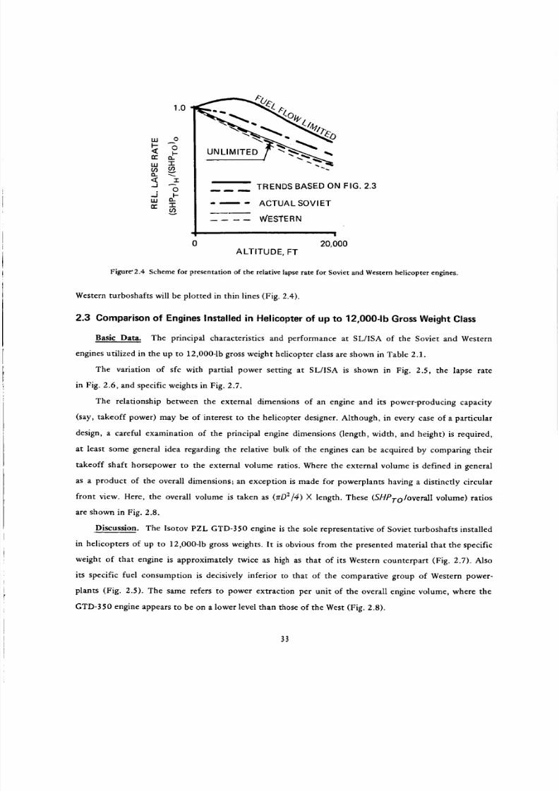
8/3/2019 Stepi Soviet 1
http://slidepdf.com/reader/full/stepi-soviet-1 43/298
1.o
,,° lu o
T
" _ m--,, --,. TRENDS BASED ON FIG. 2.3.J
rrua _ " _ - ACTUAL SOVIET
WESTE R N
0 20,000
ALTITUDE, FT
Figure'2.4 Scheme for presentation of the relative lapse rate for Soviet and Western helicopter engines.
Western turboshafts will be plotted in thin lines (Fig. 2.4).
2.3 Comparison of Engines Installed in Helicopter of up to 12,000-1b Gross Weight Class
Basic Data. The principal characteristics and performance at SL/ISA of the Soviet and Western
engines utilized in the up to 12,000-1b gross weight helicopter class are shown in Table 2.1.
The variation of sfc with partial power setting at SL/ISA is shown in Fig. 2.5, the lapse rate
in Fig. 2.6, and specific weights in Fig. 2.7.
The relationship between the external dimensions of an engine and its power-producing capacity
(say, takeoff power) may be of interest to the helicopter designer. Although, in every case of a particular
design, a careful examination of the principal engine dimensions (length, width, and height) is required,
at least some general idea regarding the relative bulk of the engines can be acquired by comparing their
takeoff shaft horsepower to the external volume ratios. Where the external volume is defined in general
as a product of the overall dimensions; an exception is made for powerplants having a distinctly circular
front view. Here, the overall volume is taken as (7rD2/4) × length. These (SHPToIoverall volume) ratios
are shown in Fig. 2.8.
Discussion. The Isotov PZL GTD-350 engine is the sole representative of Soviet turboshafts installed
in helicopters of up to 12,000-1b gross weights. It is obvious from the presented material that the specific
weight of that engine is approximately twice as high as that of its Western counterpart (Fig. 2.7). Also
its specific fuel consumption is decisively inferior to that of the comparative group of Western power-
plants (Fig. 2.5). The same refers to power extraction per unit of the overall engine volume, where the
GTD-350 engine appears to be on a lower level than those of the West (Fig. 2.8).
33
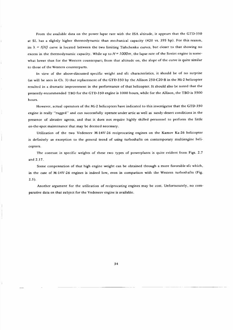
8/3/2019 Stepi Soviet 1
http://slidepdf.com/reader/full/stepi-soviet-1 44/298
Fromtheavailableataonthepowerapseatewiththe1SAaltitude,t appearshattheGTD-350
at SL has a slighdy higher thermodynamic than mechanical capacity (420 vs. 395 hp). For this reason,
its X = F(H) curve is located between the two limiting Tishchenko curves, but closer to that showing no
excess in the thermodynamic capacity. While up to H = lO00m, the lapse rate of the Soviet engine is some-
what lower than for the Western counterpart; from that altitude on, the slope of the curve is quite similar
to those of the Western counterparts.
In view of the above-discussed specific weight and sfc characteristics, it should be of no surprise
(as will be seen in Ch. 3) that replacement of the GTD-350 by the Allison 250-C20-B in the Mi-2 helicopter
resulted in a dramatic improvement in the performance of that helicopter. It should also be noted that the
presently-recommended TBO for the GTD-350 engine is 1000 hours, while for the Allison, the TBO is 3500
hours.
However, actual operators of the Mi-2 helicopters have indicated to this investigator that the GTD-350
engine is really "rugged" and can successfully operate under artic as well as sandy-desert conditions in the
presence of abrasive agents, and that it does not require highly skilled personnel to perform the little
on-the-spot maintenance that may be deemed necessary.
Utilization of the two Vedeneev M-14V-26 reciprocating engines on the Kamov Ka-26 helicopter
is definitely an exception to the general trend of using turboshafts on contemporary multiengine heli-
copters.
The contrast in specific weights of these two types of powerplants is quite evident from Figs. 2.7
and 2.17.
Some compensation of that high engine weight can be obtained through a more favorable sfc which,
in the case of M-14V-26 engines is indeed low, even in comparison with the Western turboshafts (Fig.
2.5).
Another argument for the utilization of reciprocating engines may be cost. Unfortunately, no com-
parative data on that subject for the Vedeneev engine is available.
34

8/3/2019 Stepi Soviet 1
http://slidepdf.com/reader/full/stepi-soviet-1 45/298
_.a uo
j
E,.38,4
00
",O
o..
1= _
o S. < ,.,,.,I o° '..,-. ,z', v v
v o'-.
",o
oo_
_vv
OO
O_vv
A A
, 7--, _
Z o
_<Z =
.< U
o
<6 z_ H_7,6U q _
Z _
E'-, Z _. ,
- _ _ ._-,,,_ _,_
-4
<_
Z _-.
r,1
[--.
g
t_
,,.-i
[.,
>
r,1
u'_ "o I I . 0
,_ m.o
e4 I u-_ ,_ _ _01 _'_
O0
O
• ',,O
e,i
#, --o _ -®_ R_
e4 0
u _
o
o_ _"
+-__
35

8/3/2019 Stepi Soviet 1
http://slidepdf.com/reader/full/stepi-soviet-1 46/298
ICCZ
.Jt_
Z0I--Q..
¢rj
00
..JLU
14.
C..)
L/.
LU
{tJ
0.8
0,6
0.4
0.2
[REClPROc]
PUBLISHED DATA
ESTIMATED
0
0
0.2 0.4 0.6 0.8
SHAFT HORSEPOWER RATIO: SHP/SHP.ro
1.0
Figure 2.5 Variation of sfc vs power setting for Soviet and Western engines
installed in the up to 12,000-1b gross weight class helicopters .
36
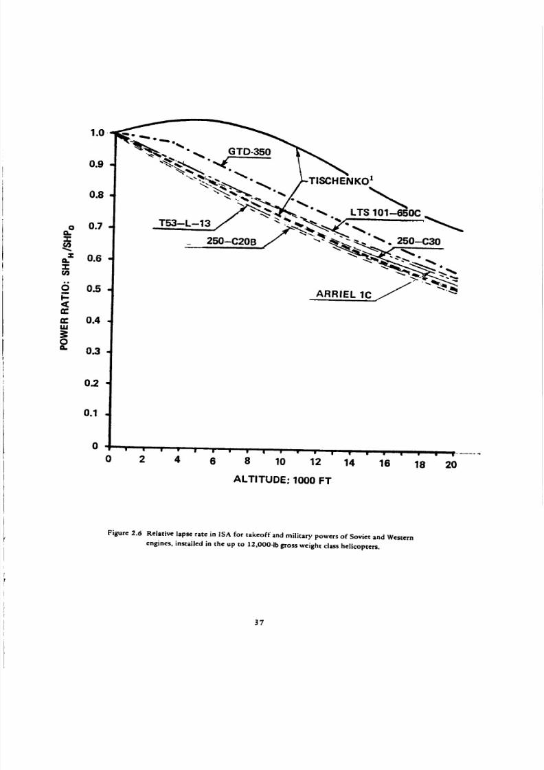
8/3/2019 Stepi Soviet 1
http://slidepdf.com/reader/full/stepi-soviet-1 47/298
O
0.-w
6m
ee
_ew
O0.
0.4
0.3
0_
0.1
0
T53-L-13
250-C20B
"ISCHENKO z
% LTS
s • • • | ! _ • q w • w ! • _ • • • _ • ......
0 2 4 6 8 10 12 14 16 18 20
ALTITUDE: 1000 FT
Figure 2.6 Relat ive lapse rate in ISA for takeoff and military powers of Soviet and Western
engines, installed in the up to 12,000-1b gross weight class helicopters.
37
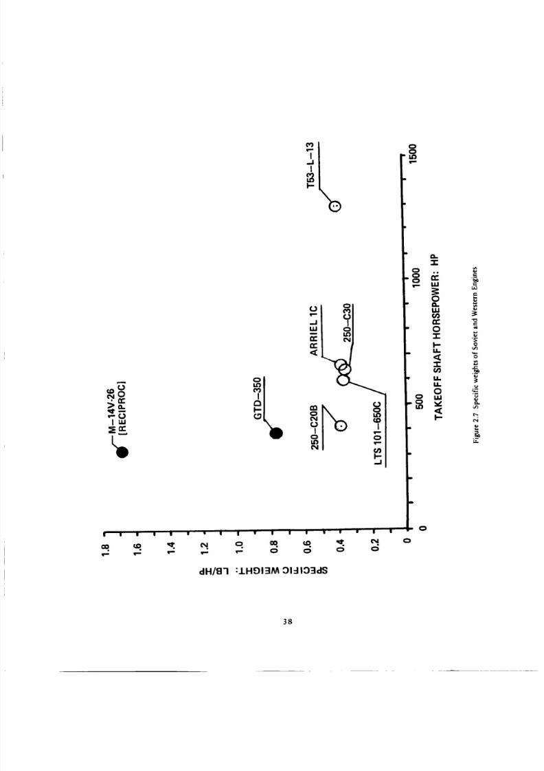
8/3/2019 Stepi Soviet 1
http://slidepdf.com/reader/full/stepi-soviet-1 48/298
U
qc,m_Ulu.I
II | II II IJ W • |
dH/8"l
qp_
I.JI
i,o t-04 00
I--.J
II • | I I II w • l
v- 0 0 0 0
:IHOI3M 01=110=ldS
ooi.o
,=,
i 0
0
e-
E
"¢l
0
e-.
u
,=_
('4
P_
38

8/3/2019 Stepi Soviet 1
http://slidepdf.com/reader/full/stepi-soviet-1 49/298
0
° ° ° 8 _ ° °'_ 0 O0 L%I
"N'no/dq :3Wf13OA "I'IYEI3AO/°J['dH S
O
E,yu
(=ql
O
O
_=
i,i
O
,-r,
O
'N
u.
P=E
39

8/3/2019 Stepi Soviet 1
http://slidepdf.com/reader/full/stepi-soviet-1 50/298
2.4 Comparison of Engines Installed in the 12,000 to 30,O00-1b Gross Weight
Class Helicopters
Basic Data. The principal characteristics and performance at SL/ISA of the Soviet and Western
turboshafts utilized in the 12,000 to 30,O00-1b gross weight class helicopters are shown in Table 2.2.
The variation of sfc with partial power setting, also at SL/ISA, is given in Fig. 2.9, the lapse rate
is given in Fig. 2.10, specific weights in Fig. 2.11, and the ratio of the S/L takeoff power to overall
engine volume is shown in Fig. 2.12.
Discussion. With respect to the Isotov TV-2-117A turboshaft, one should note that in contrast
to the GTD-350 engine, its sfc is much lower and is on the level of the older Western powerplants
of the same power class (Fig. 2.9).
As can be seen from Fig. 1,10 showing _. = f(H), the thermodynamic capacity of the TV-2-117A
engine is higher than its fuel flow-restricted power limit (at SL,ISA, 1775 hp vs 1480hp). This char-
acteristic leads to a more favorable lapse rate with the ISA altitude than for the Western counter-
parts.
However, perhaps due to material temperature limitations, the specific weight of Soviet engines
is much higher than for the Western turboshafts (Fig. 2.11). It can be seen from this figure that this
remains true, even when specific weight is based on the thermodynamic capacity horsepower (single-
flagged symbol in Fig. 2.11). In addition, the Soviet engine appears relatively much more bulky than
its Western counterparts (Fig. 2.12).
It should be emphasized at this point that all the above-discussed aspects of the TV-2-117A
engine apply to the civilian version only.
When the absolute helicopter speed record was established by the Mil A-10 (specialized version
of the Mi-24) in 1978, the TV3-117 engine rating of 2170 was used _. However, this turboshaft is
probably not an updated TV2-117, but the standard Mi-24 powerplant rated at 2170 hp.
In order to provide an example of more recent Western powerplants suitable for helicopters of
the 12,000 to 30,000-pound gross weight class, the basic data on the Aerospatiale Makila 1A engine
powering the AS332L Super-Puma helicopter was added to Table 2.2, as well as to the appropriate
graphs.
4O
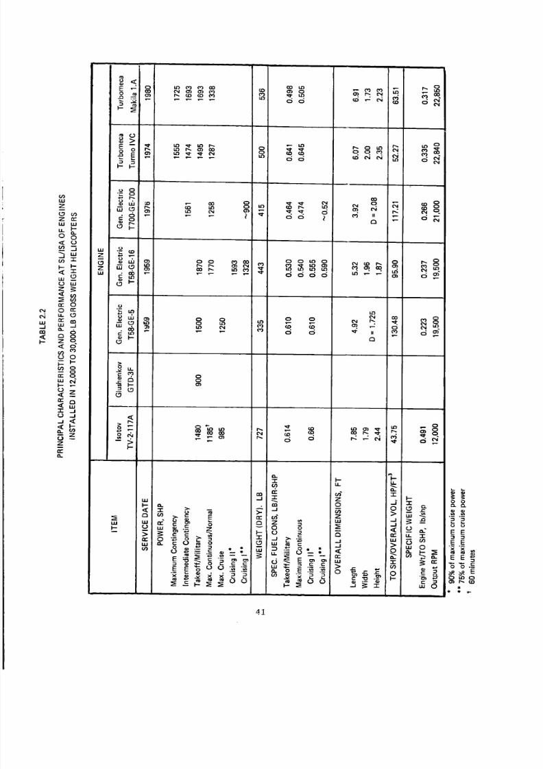
8/3/2019 Stepi Soviet 1
http://slidepdf.com/reader/full/stepi-soviet-1 51/298
cli
IE ,-_ oO0
a.i
E -- _i"
o_>O0
0 0 _ 0,1
CO _1 _ I.O 0 04
C_
LU
--I
m
t-
ILl
Z
z n-I.U I.I.I
,,,___ w
_ mne 00 a:
_ 0
-- I--
_g
_ z
•"I' - , j_ JJ _
W
z__oz
o 0
• r" 0
P_
e- 0
,_, _I
I--
I-
O0 _ li3 l"O
0 0 tO0
0
0O_
O0
0 0
d d
_ qD
0
<_ o0 o
E_
O.
- _ zm o
0 o
--I
-8=. _.' _ '"
o E _
I.i,I
I-- _,.
14.1 _.- 0
_:__ _.E E _8 u o-_ "_
O.-1-I-
j -i-0 _
,( -- _crr u. "T
0
"r _ _"
0 0
E E
_-_ __'3 O"l I"_, (.0
_uO , _
41

8/3/2019 Stepi Soviet 1
http://slidepdf.com/reader/full/stepi-soviet-1 52/298
1.2
1.0
0.8
0.6
8
,,_ 0.4
0
,"r
0.2
0
T58-GE-5
' _ " "_ TV-2-117A
\ \ "" ,_ ,."_'_"'_-- TURMO IVC
MAKILAIA/ \ "--,__
T700-GE-700 / -f
0.2 0.4 0_6 0_8 110
SHAFT HORSEPOWER RATIO; SHP/SHPTo
Figure 2.9 Variation of sfc vs power setting for Soviet and Western engines
installed in the 12,000 to 30,0004b gross weight class helicopters.
42

8/3/2019 Stepi Soviet 1
http://slidepdf.com/reader/full/stepi-soviet-1 53/298
oe_"I-
"T-e,
¢/)
6m
tw
tw
LU
O
0
T700-GE-700
0 2 4 6 8 10 12 14 16 20
ALTITUDE, 1000 FT
Figure 2.10 Relative lapse rate in ISA for takeoff and military powers for Soviet and Western engines
installed in the 12,000 to 30,O00-1b gross weight class helicopters.
43

8/3/2019 Stepi Soviet 1
http://slidepdf.com/reader/full/stepi-soviet-1 54/298
a.9"
=0
i
uJ
D
g=m
uJo.¢O
0.8
0.6
0.4
0.2
0800
CIVILIAN TO SHP RATING
THERMODYNAMIC CAPACITY
OF CIVILIAN VERSION
TV'2-117A
TURMO Ivc,._ MAKILA 1A
TV3-117
• Q
\ T58-GE-16
L II
10'00 " 1:;;00 ' 1400 " 16"00 ' 1800 _' 2d00 2200
SL, ISA, T.O SHP
Figure 2.11 Specific weight of Soviet and Western turboshafts for 12,000 to 30,O00-lb gross weight helicopters.
44

8/3/2019 Stepi Soviet 1
http://slidepdf.com/reader/full/stepi-soviet-1 55/298
O CIVILIAN T.O SHP RATING
0,, THERMODYNAMIC CAPACITYOF CIVILIAN VERSION
150 •
T700-G E-70.0
100
3O MAKILA 1A TV3-117
o o ' lo"oo" 12oo" 14oo' ' ' 1.oo'" " " 2;oo1600 2000
SL, ISA, T.0 SHP, HP
Figure 2.12 Takeoff SHP to overall engine volume of Soviet and Western turboshafts
for 12,000 to 30,O00-1b gross weight helicopter class.
45

8/3/2019 Stepi Soviet 1
http://slidepdf.com/reader/full/stepi-soviet-1 56/298
2.5 Comparison of Engines Installed in the 30,000 to 100,000-1b and over 100,000-1b
Gross Weight Class Helicopters
Combination of Two Engine Groups. Since, in the over 100,000-1b gross weight class helicopters,
there is only one nonhypothetical engine (T701) that does not appear in the 30,000 to 100,000 gross
weight class, powerplants from both categories are combined into a single study group.
Hypothetical Engines. In addition to the actual turboshafts, two hypothetical engines "constructed"
on the basis of some of the characteristics and performance assumed in the book by Tishchenko et al 1
are included in the present study. The overall picture of the so-reconstructed powerplants is far from
being complete; for instance, there is no indication regarding the physical shape of the engines and output
rpm. Nevertheless, it is believed that incorporation of even these very sketchy "hypothetical powerplants"
may shed some light on the Soviet projected trends (or at least on the desires of the Soviet helicopter
designers) in regard to their design philosophies concerning turboshafts for rotary-wing applications.
Formulation of these sketchy engine concepts is done as follows:
It is clearly stated in Ref. 1 that all 12 to 24 metric ton gross weight helicopters are of the twin-
engine type. It appears that the 44 to 60 metric ton gross weight helicopters may be of either twin, or
3-engine type. It is also stated that for the single-rotor configuration, selected here as a test case, the so-
called installed reference power (i.e., engine T.O SHP available at 500 m) per kg of gross weight should be
(see Fig. 2.631 )
SHPredWor = 0.45hp/kg
Consequently, the installed takeoff SliP related to SL, ISA would be
(SHPTO)o/Wgr = 0"45/_50o rn hp/kg
where Xb00m is the takeoff power lapse rate corresponding to 500m = 1640 ft. Assuming Tishchenko's
curve of X = f(H) for engines with matched mechanical and thermodynamic capacities (broken line in Fig.
2.10), X500m = 0.965. Remembering that theSl* horsepower (75 kg-m/s).amounts to 0.986 of the 550
ft-lb/sec horsepower, the nominal SL, ISA takeoff SHP per engine can be expressed in English units as
(SHPTo) ° = 0.21 Wgr/neng (2.3)
where rleng is the number of engines.
The (SI-/PTo) o values as given by Eq (2.3) are shown in Table 2.3.
*International System (SI) of Units.
46

8/3/2019 Stepi Soviet 1
http://slidepdf.com/reader/full/stepi-soviet-1 57/298
TABLE 2.3
T.O SHP AT SL, ISA PER ENGINE FOR HELICOPTERS OF 12 TO 24
AND 44 TO 60 METRIC TON GROSS WEIGHTS
GROSS WEIGHT
Metric Tons lb.
12
16
20
24
44
52
52
60
26,460
35,280
44,100
52,920
97,020
114,660
114,660
132,300
No. OF ENGINEST.O SHP; SL, ISA
PER ENGINE, HP
2778
3704
4630
5556
10,187
12,039.
8026
9261
Two engines are selected from this table: (1) hypothetical engine A with takeoff power at SL, ISA
assumed to be (SHPTo) o = 5500 hp (same as for the D-25V), and (2) hypothetical engine B with
(SHPTo) o = 8080 hp (same as that for the T701). The referred shaft horsepower (in SI units) for these
engines would be 5383 hp and 7908 hp, respectively.
The weights of the engines in kilograms according to Eq (2.57) 1 can be expressed as
Weng = keng(SHPref) 0"7
Assuming an average value of heng = 1.I, the weight of hypothetical engine A would be 901.8 lb and
that of engine B, 1170 lb. Specific fuel consumption at takeoff rating (p. 1231) in gr/hp-hr would be
=k H OlSfCro Ce/(S Pref)max
0.9
Taking an average value of hce --- 495 gr/hp -hr, the following is obtained: for engine A, sfcro = 0.462
lb/hp-hr, and for engine B, ShPTo = 0.445 lb/hp-hr.
Variation of sfc with partial power setting is given by the following formula (Eq (2.1611)), where
the results are in kg/hp-hr, and SFcTO is given in the same units:
sfc = {SfCro - O.16[ l -- (SHPISHPTo) ]}/(SHPISHPTo)
47

8/3/2019 Stepi Soviet 1
http://slidepdf.com/reader/full/stepi-soviet-1 58/298
The normal rated power is assumed as
SHPN. R _ 0.92SHPTo (p.119 x)
Basic Data. The principal characteristics and performance of the real and hypothetical powerplants
at SL, ISA are given in Table 2.4. The sfc consumption as a function of partial power setting (also at
SL, ISA) is shown in Fig. 2.13; lapse rate in Fig. 2.14; specific weights in Fig. 2.15; and TO SHP per cu.ft
of the engine vol_ame (defined by its external dimensions) is shown for real engines in Fig. 2.16.
Discussion. It can be seen from Fig. 2.13 that similar to the previously discussed engine classes,
the specific fuel consumption of the D-25V (TV-2BM) turboshaft is higher than that of its Western coun-
terparts. However, for Tishchenko's hypothetical engines, it is practically the same as for the advanced
powerplants and is even better for the new D-136 disclosed at the Paris Air Show in 1981.
As can be seen from Fig. 2.14, the previously mentioned design philosophy of providing a larger
thermodynamic than mechanical engine capability at low altitudes and then restricting the power through
fuel flow limitation is even more visible in the D-25V (YB-2BM) engine than in the other Soviet turbo-
shafts. By contrast, the so-called hypothetical engines apparently would have matched thermodynamics
and mechanical capabilities; thus their relative power lapse rate vs ISA altitude should be similar to those
of the American turboshafts. Unfortunately, in this respect, there is no available data in regard to the
D-136. However, the goals regarding specific weights as set up in Fig. 2.15 have been closely approached in
the D-136 turboshaft.
Fig. 2.16 clearly shows that, as may be expected, the D-25V (TV-2BM) engine is much more bulky
than the Western ones. Again, no data is available as yet on the D-136.
2.6 Concluding Remarks
From the comparative material presented in this chapter, it appears that from the performance point
of view, Soviet helicopter powerplants have been definitely inferior to their Western counterparts. Whether
those performance and weight deficiencies are compensated, if at all, by such aspects as ruggedness, ease of
maintenance, and operational reliability, are outside of the scope of this part of the comparative study.
It appears that Soviet helicopter designers realize that their present powerplants are inferior to those
of the West (which is clearly discernable from such comparisons as depicted in Fig. 2.17) and thus, in their
hypothetical concepts, they assume performance and weight characteristics representing the current West-
ern state of the art. Characteristics of the D-136 turboshaft tend to indicate that the general goals of the
hypothetical engines served as milestones of the actual development program.
48

8/3/2019 Stepi Soviet 1
http://slidepdf.com/reader/full/stepi-soviet-1 59/298
Z
c_a,--I
<
Z
Z
Z_.
<
e.iZ-
.1
_g
<
,.4<
Z
eL
w w
o
s_
o
W
O --
7-
O --
"I"
5;em
6
w
I--
_ o
>n-
ill
oooo _% o_ I_ _" 0 _ 0 I_
°N
_o _00_
o
_ rr
-r" _ .i= _1
_ ® >" ..rr
-- "._. _ _ _ +- _ z_ <% - o
0 _ o _ .
_ * . _" 8_._ ___ ,,,
E E "6 o o ._- ..z
o o o
",.0 ',.0t..O _.
00
0000
OOc_d
g_
o c_
go
O O
O
W '_ "_
tO
co _
¢0 II 0_1
13
_oCO CO "7.
_ 0oCO
t.O II
00
• _ o'Jt.O U _r
m
_ 0
Illl
I I I
mmm_
ii
Z
oOzILl Z-"
o _=_._o,_
,:sZ
d
I.,0
,5
t,.O
_5
I,.0
0
__. ou. i,-
E0
ol
O.
g_s',_, _ _
ot-
"r
O
gg_,._ ._ o_
E
00
N N
E E
• m.
z * **
49

8/3/2019 Stepi Soviet 1
http://slidepdf.com/reader/full/stepi-soviet-1 60/298
1.0 \
%%.
T55-L-712 %=-- . _._ D-25V(TV-2BM)
0.8 ,. / .. / ......HYPOTHETICAL A _"t _ _'
HYPOTHETICAL B ,_."_, _ "_
.T64-GE-415 /" -*"- _ __._._, . • '=... ___ _
QT64-GE413
u 0.4 D 136,,-I,u_
0m
m
0ulQ,.
0.2
0 • • • • J _ • • vt9 •
0 0.2 0.4 0.6 0.8 1.0
|
1.2
SHP/SHPTo
1.4
Figure 2.13 The sfc vs partial power setting of Western and Soviet turboshafts for
30,000 to 100,000, and over 100,OOO-]b gross weight class helicopters.
50
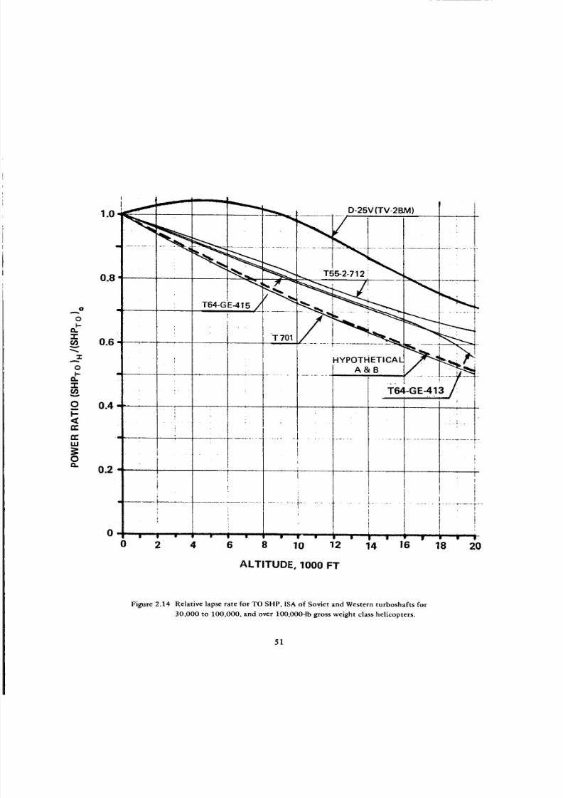
8/3/2019 Stepi Soviet 1
http://slidepdf.com/reader/full/stepi-soviet-1 61/298
I
I
1.0 D-25V(TV-2BM)
iO .. ".......... _ f ...... _ ........ t
4GI0.6 i-_0,,.............. .----__ .......
o ...... I _. L/.....1._'__
__ ' T6,_-o_-4,_,0 0.4 "- ! I : '
i
...... ; ;."
:
m
I,-<C
eeLU
0
0.2i
t
.... i
i
, i i
0 2 4 6 8
_.L
i
!I
i1
i
i
i
i i
i !
fi i
!
i
i
i
......... _.......... ,+
1 r iI :
10 12 14 16 18 20
ALTITUDE, 1000 FT
Figure 2.14 Relative lapse rate for TOSHP, ISAof Soviet and Western turboshafts for
30,000 to 100,000, and over 100,000-1bgross weight class helicopters.
51
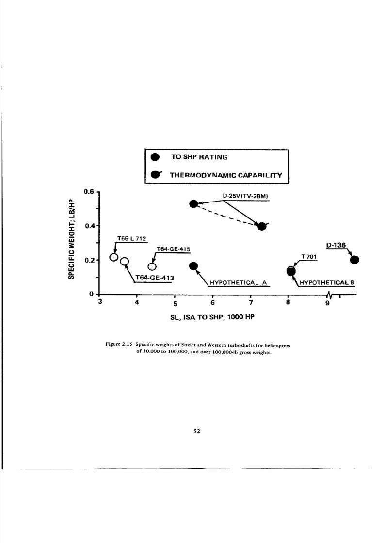
8/3/2019 Stepi Soviet 1
http://slidepdf.com/reader/full/stepi-soviet-1 62/298
0.6
o.-!-
..I
_" 0.4-r"
IJ.I
u. 0.2¢JI,IJQ.
0
TO SHP RATING
TH ERMODVI_IAM IC CAPABI LITY
3
D-25V(TV-2BM)
T5_ L-712
(_ T64-G E-415
A
D-136
T 701
CTHETICAL B
| I I I
5 6 7 8 9
SL, ISA TO SliP, 1000 HP
Figure 2.15 Specific weights of Soviet and Western turboshafts for helicopters
of 30,000 to 1OO,O00, and over lOO,O00-1b gross weights.
52

8/3/2019 Stepi Soviet 1
http://slidepdf.com/reader/full/stepi-soviet-1 63/298
3OO
200
o
_> 1.00
0I-
0
O TO SHP RATING
TH ERMODYNAMIC CAPAB! LITY
T55_L-712
(_T.64-GE-413
gl • • •w
3 4 5 6 7 8 6
SL. ISA TO SliP; 1000 HP
Figure 2.16 SL, ISA Takeoff SHP to overall engine volume for Soviet and Western turboshafts for
30,000 to 100,000, and over lO0,O00-1b gross weight helicopters
53

8/3/2019 Stepi Soviet 1
http://slidepdf.com/reader/full/stepi-soviet-1 64/298
M-14V-26
[RECIPROCATING]
0.8
0.7
-_r (3TU-3bU
0.3 •
m
-r
rn.-I
0.6
O.
'1"
0.5 OV
I
0.4 (j
LL
iii0.
0.3
0.2
b
I e D-25V (TV-2BM
e TV-2-117A
_jr_Astilzou III I_Gazelll} / ,.,
0.2 _[;;L,A"'=_-o c2o" . I 1
V_."'._ L_con,,nQ-s3-L-_(Ho,,C_,,)_/./_: BS-3C:W:)(V-/3 Un.) _ "1'
×,vT %',_I///,'_ "_ Turmo Ill C4 (Puml)
' _TT_(AGs:EAA2H) _ "_'-_ E'6 (¢ H'53A | L A I
(U $ :A A H |///'_l)_ s- T_4 I HYPOTHETICA
_._ -GE-3 (HH-53B) _.._...._._--._.,_m__ .
I.Y OT. T,CA',-,om'_ " , / ir-'-T--. , -.,
O o • 1400 " _¢n "f4
, /r I-L T-SS-L-7C(CH47B) T.6,4-GE-I(CH-53C) T'7OI(HLH}I Renal " 1"0
0 5 000 10 000
ENGINE REFERREDSHP
Figure 2.17 General comparison of specific weights of Soviet and Western helicopter engines.
54

8/3/2019 Stepi Soviet 1
http://slidepdf.com/reader/full/stepi-soviet-1 65/298
Chapter 3
Helicopters of the Up-to-12,000-Ib Class
3.1 Basic Data
Three-view drawings of the compared helicopters are shown in Figs. 3.1a through 3.1h, while their
principal characteristics are given in Table 3.1. Some of the data contained in this table are graphically
presented in Figs. 3.2 through 3.7.
Disc Loading (Fig. 3.2). From this figure it can be seen that the disc loading of Soviet helicopters
belonging to the up to 12,000-1b gross weight class is not only much lower than that of the more recent
Western helicopters of the same class, but is also lower than the disc loading of the older types represented
here by the UH-1H helicopter.
Power Loadinl_ (Fig. 3.3). In contrast to the disc loading, the power loading of the Soviet rotorcraft
is much higher than that based on the takeoff power inst_lled (unflagged symbols), hut is also higher than
the Western power loading associated with transmission limits, or engine flat rating (flagged symbols).
Main Rotor Tip Speed (Fig. 3.4). Main rotor tip speeds of the Soviet helicopters of the considered
class are of slightly over 600 fps magnitude, while those of the Western helicopters are usually in the 700
fps class, with some Bell helicopters reaching, or even exceeding, the 800 fps limit.
TaR-Rotor to Main-Rotor Radii Ratio and Relative Tail-Rotor Distance (Fig. 3.5). It can be seen
from this figure that the rotor radii ratio of the Soviet helicopters is only slightly higher than the corre-
sponding ratios of Western counterparts. SA-365N represents an exception to this rule, since the radii
ratio is significantly lower for the Fenestrone tail-rotor configuration.
The relative distance (_) of the Mi-2 tail-rotor location is practically the same as those of Western
helicopters.
Weight Empty and Zero-Range Payload to Gross Wei[ht Ratios (Fig. 3.6). Trends visible from this
figure indicate that the weight empty to gross weight ratios of Soviet helicopters are higher for both normal
and maximum flying gross weights than for their Western counterparts. Consequently, the zero-range (or
time) payload to gross weight ratios of the Soviet helicopters are lower than those of Western helicopters.
Cabin Volume Loading at Zero-Range Payload (Fig. 3.7). It can be seen from this figure that with
respect to the provision of cabin volume for the possible maximum payload (as expressed by the zero-
range payload), there is no common trend in the Soviet helicopters of the considered gross-weight class.
While the Mil designs provide a large cabin volume for the possible payload (resulting in a cabin loading
way below Western practice), Kamov's design is more consistent with the Western trend, with the excep-
tion of the BO-105.
55

8/3/2019 Stepi Soviet 1
http://slidepdf.com/reader/full/stepi-soviet-1 66/298
.,.n
e,n _ 13_
_o.',n
'1"
C)
¢lr
"" ,,-.l I'-
2P= 8c._
<©
N <
.-/ _ er
W
I--
_1
e-- 0
E.3 oomm_CC
80
#<
>co o
_"r, o
e_
_ o
.iJ
z a.o__ t.- a_:=
n,- .a = E .,-; E O
,, ._,_ _.,!
Z 0 .
'_ '_ O O _,,
OCO
O
,,5 _ c5_.
z
o_ _ _o _ _ _0
E£
"E
"O
#:,.-,._o" _"
m d m_ _'_, x m. co
C)
Z
_ _SZs
Z
{co
"O O
"" _ ,.._-,,._O
o0..
ii
.q
_00
u_ _ 00c°m
_r _ e_ I _ c5 c5 _
0 _"-0 0
mr- _. e-
, _ "s_ .o ,.
_- _ _=_z_<_'_
56
M') 0 _- )
O) ('_3 t.O
es_
E
_o.
r"_ P'-. O)
rZ_e4
Z
0
Z
-_ =_'

8/3/2019 Stepi Soviet 1
http://slidepdf.com/reader/full/stepi-soviet-1 67/298
',.0 _" ,,_4 ('%1
0
o6
('%1 "_.
¢_1 C,I
0 ,'q ',¢, e6
('%1
°_ -("9 ("4
O0
_ o
N66_ _ mm. me4ddo_
Z
O
¢Jl
z
• n"
<z _=EEn- u -, :m _"
,,, ,-. E E E
-- o_>
___ _, ,_'_
•_:__°_
@
0
Z
@
A@
@
m
@ >
D
UJ
o ,.J '- _'.£
z z _ E ,,.,,_ z
z '_, • ,,,.[._- g
_ ,,o.._-_:._
('9 UO
,_" C'4
_5_o
O_ C,4
£CO _J eO
b-
E
b-
E"q i-,. 00
b-
COI,O
(.O
IX)
I o
m- o
57
Z
°E
O
z_
o r-
E_J (_9
_" O
O _
b-
O 00 O_
F-
o__- c6d
ob-
(.9
Z ,'_
_ ¢..
q_-_-e
_ _._
EO
O
"5¢-
O
CI.
U_
+
"O
8
e_
-TO(%1
e- e-
0 "_
£
* _
e-
< o
66U.I
I--
O
Z

8/3/2019 Stepi Soviet 1
http://slidepdf.com/reader/full/stepi-soviet-1 68/298
(a) PZL-Swidnik (Mil) Mi-2 twin-turbine general-purpose light helicopter (Pilo t Press)
(b) PZL-Swidnik Taurus: Mi-2 with
two Allison 250C-20B engines
Figure 3.1 Three-view drawings of Soviet and Western helicopters of the up to 12,000-1b GW class.
58

8/3/2019 Stepi Soviet 1
http://slidepdf.com/reader/full/stepi-soviet-1 69/298
(c) Kamov Ka-26 twin-engined flight general-purpose helicopter in passenger-carrying form (Pilot Press).
(d) Aerospatiale SA-365N Dauphin 2
Figure 3.1 Three-view drawings of Sov iet and Western helicopters of the up to 12,000-1b GW class (Cont'd).
59

8/3/2019 Stepi Soviet 1
http://slidepdf.com/reader/full/stepi-soviet-1 70/298
(e)BellUH-1Hroquois.
(f) BellModel22twoAvcoLycomingTS101urboshaftngines)Pilot Press) .
Figure 3.1 Three-view drawings of Soviet and Western helicopters of the up to 12,000-1b GW class (Cont'd).
60

8/3/2019 Stepi Soviet 1
http://slidepdf.com/reader/full/stepi-soviet-1 71/298
(g) Bo 105 CB five-seat light helicopter (two Allison 250-C2OB turboshaft engines) (Pilot Press).
(h) Sikorsky S-76 eight/twelve-passenger commercial transport helicopter (Pilo t Press) .
Figure 3.1 Three-view drawings of Soviet and Western helicopters of the up to 12,000-1b GW class (Cont'd).
61

8/3/2019 Stepi Soviet 1
http://slidepdf.com/reader/full/stepi-soviet-1 72/298
|
u.I
\
143
-ISd :gNIElVO"I OSI(]
CO,.J
ooo
w
0
O
0
E
0
e_
E0
0
62

8/3/2019 Stepi Soviet 1
http://slidepdf.com/reader/full/stepi-soviet-1 73/298
dHS/9"I :ONlaVO'I Id3MOd
63

8/3/2019 Stepi Soviet 1
http://slidepdf.com/reader/full/stepi-soviet-1 74/298
i
Z
I
Sd"l :CFI3dS dll
64.
-I
ooo
"I"
m
ILl
O0:r_
<C
_J
,.Q"r'
0
e_
0u
u
E
0
0
.E
E
E0
u
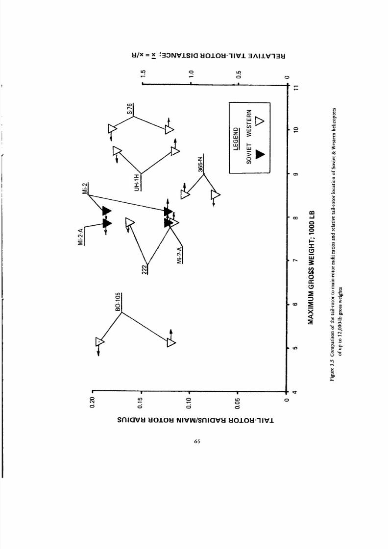
8/3/2019 Stepi Soviet 1
http://slidepdf.com/reader/full/stepi-soviet-1 75/298
EI/X = x '30NVISIO I:10101:1--IlVl 3AIIV'13EI
Q i£)
_'- d
I__ _ I , , I
o
z
,,=,>
TMF-LU
O0
LO
I | ! I
d d d d
SNIQVH EIO.LOI:I NIVIN/SNIQVI:i t:IO.LOU--IIV/
0
0e--
IX)
0o '-J
0C_0
,I-(.0
UJ
0
GO
com
X
I£)
r-
E
0
e.,
0
0
C
E
i
00
oo
"_, _
O _
e_
65

8/3/2019 Stepi Soviet 1
http://slidepdf.com/reader/full/stepi-soviet-1 76/298
_ z=
S_o_
I
I
iI
!
0
1HOI3M SSOI:I O
C]VO'IAVd :IONVI=[ OId=lZ
O O O
, I I i I
cb
_-x,l_(_l _1_ _l
I
I t
/ \
I I |
c5
1HOI3M SSOIdO/AldlAI3 1HOI3M
C3
cr_
nn
_1
0
C3C3
00 _'-
-r"(.0
U.I
0
I,D
1.0
o
o.
o
.=
o
2:
o
o
o
o
o
o
',q.e_
66

8/3/2019 Stepi Soviet 1
http://slidepdf.com/reader/full/stepi-soviet-1 77/298
I
N
(v)
m x0 '<z
zc_
ot>IJJ
zLU
(,y,)
"0
m 4 e
J.=l'l'lO/t]-I :qe°A/°ld :_)NIQVO'I =IINN'IOA NIt]V:)
o
o3
l=3..J
00 o
"I"
¢3
uJ
I_ ¢/)¢/)on..
(D
143
O
¢1
0
60
o
o
eL
0
e-
,>
e_
67

8/3/2019 Stepi Soviet 1
http://slidepdf.com/reader/full/stepi-soviet-1 78/298
3.2 Hovering and Vertical Climb Aspects
Table 3.2 was prepared using the data contained in Table 3.1. This was done by selecting those gross
weights for which the largest number of hovering and vertical climb performance terms could be found
in published documentation.
It can be seen from this table that, following the approaches outlined in Ch. 1; first, the main-rotor
and then the tail-rotor aspects are considered. Once the figure of merit of the main rotor and the power
ratio of the tail to main rotor is estimated, the overall transmission efficiency, as well as the overall heli-
copter figure of merit, is computed.
Next, the estimated values of the overall figure of merit of the helicopter are compared with those
resulting from the published hovering OGE data and engine characteristics, including the power lapse rate.
The obtained FMoa values are compared with the estimated values, and arithmetic means of both
are given as average overall FM in Table 3.2.
Assuming that the so-compared overall figures of merit are more nearly correct than either the esti-
mated ones or those computed from published hovering OGE data, the vertical rate of climb at S/L, ISA
and TO power rating is computed from Eq (1.9), and the so-called VTO gross weight determined from
Eq (1.2).
Some of the items either directly appearing in, or easily obtainable from, Table 3.2 are graphically
presented in Figs. 3.8 through 3.I4.
Power per Pound of GW in Comparison with the Ideal Power (Fig. 3.8). It can be seen from this
figure that Soviet helicopters in general exhibit a lower ratio of takeoff specific power to ideal specific
power than their Western counterparts. This is true at both normal and maximum gross weights. However,
for those Western helicopters which encounter transmission limits, or have fiat-rated engines (flagged
symbols), the takeoff to ideal power ratios become similar to those of the Mi-2A helicopters.
Average Blade Lift Coefficient (or CT/O) in Hover at SL, ISA (Fig. 3.9). The trend indicated in this
figure shows that all Soviet helicopters (in the up to 12,000-1b GW class) operate in hover at SL, ISA at
higher average blade lift coefficients (CT/O) than the Western ones. This aspect of their design philosophy
probably reflects two facts: (1) lesser concern of the Soviets regarding operations at high altitudes and/or
high ambient temperatures; and (2) a desire to operate at the _ values as close as possible to those corre-
sponding to the maximum FM values. This latter aspect becomes a necessity because of their higher than
Western power loadings which, in turn, may reflect the fact that Soviet engines exhibit much higher specific
weights than their Western counterparts.
These high c'/7 (CT/O) values may be detrimental as far as controllability margins are concerned,
especially at higher altitudes and/or elevated ambient temperatures.
68
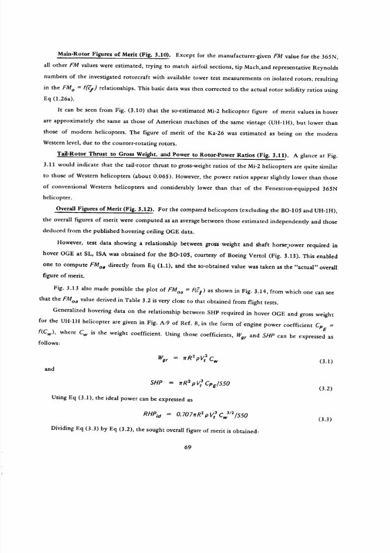
8/3/2019 Stepi Soviet 1
http://slidepdf.com/reader/full/stepi-soviet-1 79/298
Main-Rotor Figures of Merit (Fig. 3.10). Except for the manufacturer-given FM value for the 365N,
all other FM values were estimated, trying to match airfoil sections, tip Mach,and representative Reynolds
numbers of the investigated rotorcraft with available tower test measurements on isolated rotors; resulting
in the FM o = f('_) relationships. This basic data was then corrected to the actual rotor solidity ratios using
Eq (1.26a).
It can be seen from Fig. (3.10) that the so-estimated Mi-2 helicopter figure of merit values in hover
are approximately the same as those of American machines of the same vintage (UH-1H), but lower than
those of modern helicopters. The figure of merit of the Ka-26 was estimated as being on the modern
Western level, due to the counter-rotating rotors.
Tail-Rotor Thrust to Gross Weight. and Power to Rotor-Power Ratios (Fig. 3.11). A glance at Fig.
3.11 would indicate that the tail-rotor thrust to gross-weight ratios of the Mi-2 helicopters are quite similar
to those of Western helicopters (about 0.065). However, the power ratios appear slightly lower than those
of conventional Western helicopters and considerably lower than that of the Fenestron-equipped 365N
helicopter.
Overall Figures of Merit (Fig. 3.12). For the compared helicopters (excluding the BO-105 and UH-1H),
the overall figures of merit were computed as an average between those estimated independently and those
deduced from the published hovering ceiling OGE data.
However, test data showing a relationship between gross :weight and shaft horsepower required in
hover OGE at SL, ISA was obtained for the BO-105, courtesy of Boeing Vertol (Fig. 3.13). This enabled
one to compute FMoa directly from Eq (1.1), and the so-obtained value was taken as the "actual" overall
figure of merit.
Fig. 3.13 also made possible the plot of FMoa = f(_'g) as shown in Fig. 3.14, from which one can see
that the FMoa value derived in Table 3.2 is very close to that obtained from flight tests.
Generalized hovering data on the relationship between SHP required in hover OGE and gross weight
for the UH-1H helicopter are given in Fig. A-9 of Ref. 8, in the form of engine power coefficient CPE =
f(Cw), where Cw is the weight coefficient. Using those coefficients, Wor and SlIP can be expressed as
follows:
Wgr= C., (3.1)
and
SHP = rtR2 p V_ CPE/550
Using Eq (3.1), the ideal power can be expressed as
RHeid = 0.7071rR2 pVt a CJ/2/550
Dividing Eq (3.3) by Eq (3.2), the sought overall figure of merit is obtained:
(3.2)
(3.3)
69

8/3/2019 Stepi Soviet 1
http://slidepdf.com/reader/full/stepi-soviet-1 80/298
nn
<
<c_ n-
t.I.J
0
--1 c._
<
F-o
>6
zo
;>0
®_ _ _ _ °_o _
LO
-r
_)
_ o _dd_d_ O_omd
_._ _,__ _. ,g_0_.o_ 0 "
0
I--
..= 0 _ C, I_
-r _r _.- __
o o ""
r_ _ o _---m >o-- _
_ -o__ _c_ _ _u-
_ o_g_® • _ __d _d d_d o
o _°_o _ g _d_d d_d o
d _d d_ _ o mo d_d o d
6 _d_ d Oo
_R_ _o _ _
_d _ d
0
0 0
._ _o _Odd o d
• _ c_ ° _ _" _ c5 o c:5 o o
Q;
0
o
nr-
0
I-.0n-
-.I
I.-
oZ
Lt.J
1.1_
.-I
n,"
0
U_
.--I
_1
n"
0
70

8/3/2019 Stepi Soviet 1
http://slidepdf.com/reader/full/stepi-soviet-1 81/298
d _ _
oco o c_
t_
c_
oo
odd
_dd,, o oo
Ill
0
J _ E•- -_ -_o
'__ _ _- _-_-
n" "r _ ,w" 0 -r -r
68
0Z
.M
._=
0 0
c9
_.__- E._ _
.- ,_ .E_
* +- 44-
71

8/3/2019 Stepi Soviet 1
http://slidepdf.com/reader/full/stepi-soviet-1 82/298
a {3 i3
-1- -1- -1- ,_
• ./ '_ tq ,-: o
\1>12,/ , ,\ rr.\ ,t_ , I
', 1
_ , \if)
o
I
_J
_ z
_ X -
_ L_
"J I-- _W _
_o_ _,0 "
, , \
"\' \\
, \\\
',,,\,\\
I • l I | l _ I I
ql/dq :M'9:10 (]NnOcl U3a U3MOd
_D
LO
N--
Q.
Z
t_
0,-I
(.I
.o
0
o
0
0
._90
0
c
0
.'2.
o
"C,
0
0
e_
0
72

8/3/2019 Stepi Soviet 1
http://slidepdf.com/reader/full/stepi-soviet-1 83/298
1N3101-I:1300 1-117 :IOV18 30VI:I::IAV
| | | W i
*-- 0 0 0 0
d o o o o
e_
,<
©
<
73
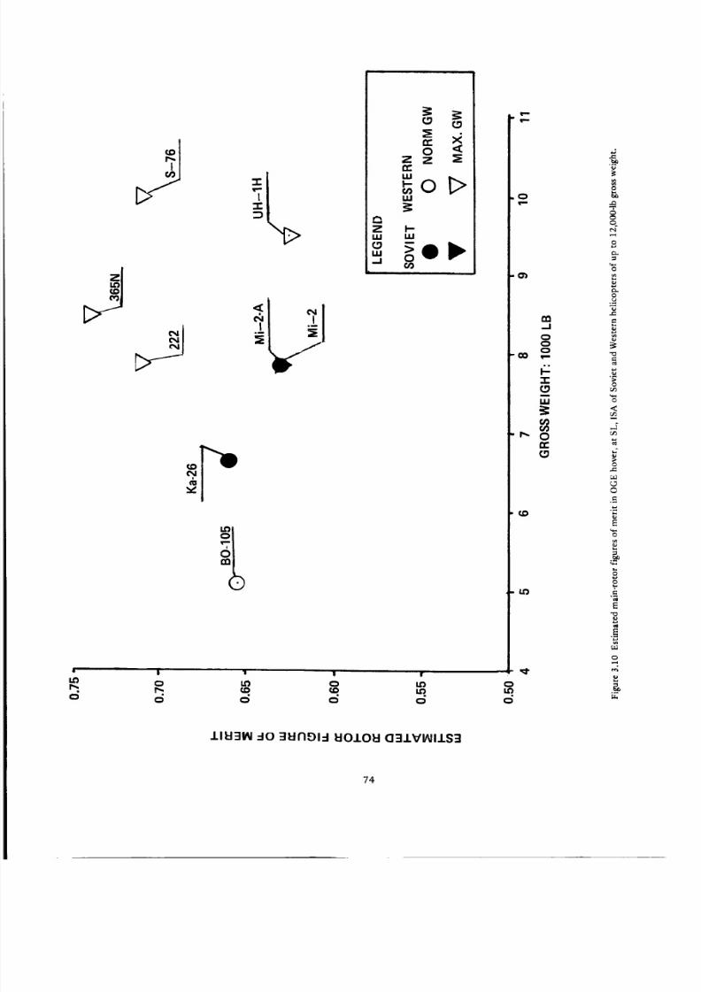
8/3/2019 Stepi Soviet 1
http://slidepdf.com/reader/full/stepi-soviet-1 84/298
j
• II 1 l •
LO 0 LO 0 LOI_ _ _0 CO LOc_ c_ c_ c_ c_
,o1>ILl
Z _-,,, LU
c_|
om.o
o
crJ
al.-I
ooo
co ,e-
"I-
I
ILl
r_ 0CC
¢D
0
e",
0
0
or4,.q
o
o
E
0
<i
0
©
E
}
0
E
0
II_131_I -I0 3_INOl-I 1:10101:1031VI_IIS3
74

8/3/2019 Stepi Soviet 1
http://slidepdf.com/reader/full/stepi-soviet-1 85/298
.I.HDI3M SSOEID/.I.SI')EIHJ. _10.1.01:1"IIV.I.
1.0 0 It')
I,- t,.- 0 C3
! II I
n.. X0z =E
zn,"u.I
oDW
0
N
I:l:lMOd IdO.LOl:l NIVIN/Id=IMOd I:lO.LOId "IlV.L
t""
O_
00
f_
cO
I.q
IZ)-.I
C_C_
-1-
IJJ
r,,/)¢00n,-
e-,
o
P4
m.,
,..i
e-.
.=
0
0
0
e-,
E
,?
0lz.
,?o
0
PP_
75

8/3/2019 Stepi Soviet 1
http://slidepdf.com/reader/full/stepi-soviet-1 86/298
Z
_-01_I.u
Z I--Li.I ILl
-
_1 _,L
o
t_ u ! n
,-I
0o
"I"
w
ILl
0
0
0
_a
_a
_a
111:131AlI0 3UnOl-i TIV_I3^O
76

8/3/2019 Stepi Soviet 1
http://slidepdf.com/reader/full/stepi-soviet-1 87/298
fl)..I
-r
m
tu
¢tJoee
5,600
5,200
4,800
4,400
4.000
- /_0 400 500
//
/
/Q TEST DATA,
600 700 800 900 1,000
SHAFT HORSEPOWER: LB
Figure 3.13 Correlation of theory with BO-tOS flight-test data in hover (Courtesy of Boeing Vertol Co.)
FMoa = O. 707CwS/2/Cp_ (3.4)
An expression for the average blade lift coefficient based on C w can also be obtained from Eq (3.1) as
_ = kvh 6Cw/O (3.5)
Using the data presented in Fig. A.9 s, the FM o = f('3_, ) curve was calculated for the UH-1H, and the
results are shown in Fig. 3.14. Here, it can be seen that, as in the case of the BO-105, the value of the over-
all figure of merit as obtained in Table 3.2 is very close to those resulting from flight tests.
In the case of the 365N helicopter, a SlIP = f(V) curve as SL, ISA is shown in Fig. 5 of Ref. 9 for
Wg r = 7055 lb. Taking advantage of this data, FMoa was computed from Eq (1.1). The so-obtained FMoa =
0.523 is somewhat lower than the average value of 0.534 shown in Table 3.2; but this may be expected
since FMoa = 0.534 corresponds to-d I = 0.534, while FMoa = 0.523 corresponds to _e = 0. 72.
The above three cases should give some degree of confidence in the accepted method of providing
the FMo= values of the compared helicopters.
Going back to Fig. 3.12, it can be seen that the FMoa values for the Mi-2 helicopters are approxi-
mately on the same level as those of the BO-105 and UH-1H, lower than for the S-76 and 222, but higher
than for the 365N. As far as the Ka-26 is concerned, its overall figure of merit (due to the counter-rotating
configuration) is higher than those of Western helicopters.
77

8/3/2019 Stepi Soviet 1
http://slidepdf.com/reader/full/stepi-soviet-1 88/298
¢t)I-of)I.Up-
I-"I"
_1IJ..
OnrI1
u.II--_)a.
OC.)
I
III
r_i.u
m
l-et)ILl
©
ann0C
IL
Z0
a
0
\
0
U_
0
IlEI3W 40:11:11"1014 -I'IVI=I3AO
78

8/3/2019 Stepi Soviet 1
http://slidepdf.com/reader/full/stepi-soviet-1 89/298
VTO Gross Weight. VTO gross weights (defined here as the Wgr corresponding to hovering OGE at
3000-ft altitude ISA) were calculated for the compared helicopters using Eq (1.2) and listed in the last
row of Table 3.2. Here, it can be seen that for Soviet Mi-2 and Ka-26 helicopters the so-called VTO gross
weights are lower than their normal gross weights, and are below the maximum flying weight of the Mi-2-A
helicopter. By contrast, the VTO gross weights of the Western rotorcraft either exceed the maximum flying
weights (BO-105, Bell 222, UH-1H, and SA-365N) or, at least, are almost equal to the maximum gross
weight values (S-76).
Vertical Rates of Climb. Vertical rates of climb at SL, ISA and T.O engine power setting as computed
from Eq (1.9) are listed in the third row from the bottom of Table 3.2. These values refer to the gross
weights indicated in the first row, and are plotted in Fig. 3.15.
In addition, the vertical rates of climb were also calculated for the VTO gross weights and indicated on
this figure. It is interesting to note that for helicopters having transmission-limited power inputs (BO-105,
222, and UH-1H) or flat rated engines (Mi-2), the vertical rate of climb at (Wgr)Vr 0 is about 180 fpm;
while for powerplants exhibiting a continuous decrease of power with altitude, the vertical rate of climb at
the VTO gross weight is about 500 fpm.
3.3 Energy Aspects in Hover
Table 3.3. The most important inputs required in the study of energy aspects in hover, as well as
numerical values of hourly fuel consumption per pound of gross weight and zero-time payload are in-
dicated in Table 3.3. The results are also graphically presented in Figs. 3.16 and 3.17.
Hourly Fuel Consumption per Pound of GW in Hover, OGE, SL, ISA (Fig. 3.16). It is interesting
to note that with the original GTD-350 engine, the Mi-2 helicopter has one of the highest relative hourly
fuel consumption of all compared helicopters. Through installation of the Allison 250-C20B turbines,
this consumption is brought to a lower level than that of the Western counterparts. One's attention should
also be called to the low relative fuel consumption of the Ka-26-resulting from its high FMoa values, and
from the utilization of reciprocating engines.
Hourly Fuel Consumption per Pound of Payload in Hover, OGE, SL, ISA (Fig. 3-17). This figure
clearly indicates that the original Mi-2 helicopter exhibits much larger fuel consumption related to the
payload than any other compared helicopter. Installation of the Allison turbine in that aircraft results in
a very considerable improvement, placing that machine on the same level of hovering fuel economy as
several Western helicopters.
It should be noted that the hovering fuel economy of the Ka-26 aircraft remains close to that of the
Western representatives, in spite of its low WPlo/Wg r ratio.
79
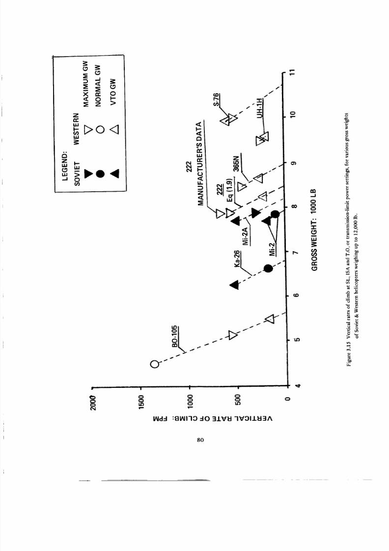
8/3/2019 Stepi Soviet 1
http://slidepdf.com/reader/full/stepi-soviet-1 90/298
:_z° >
_Do,q
.__o4
• i ii ii |
01.0
¢g')
/f
0
+L
°t
a\+ .e+. t_
s
i iii |
Q 0O
,,ml"
laid-.! :glNI'lO dO 31VU -IVOIIEI3A
B
i..,
q_- .=_
_=.=<_
-- S
8
_._
M
8O

8/3/2019 Stepi Soviet 1
http://slidepdf.com/reader/full/stepi-soviet-1 91/298
,-I
.< 0
_Sz_B
_ o
_. _, _, o . • . .
o
d o o o
=_.,
8 aS
_a
_ _ _ ,_ _ _ _, _._"z _ _ ° _ _ __ _ ,_ . - . _
•- 00 ,_. _.. _ _
.,I _ _
_ ,-_ ._- _ _ _'_,
_ " _ o o '_, o_
_- -_. - __ __ _ _ _ _ _ _ -_
- ._. _0 _ _ _ _ "_ _ "_ o
81

8/3/2019 Stepi Soviet 1
http://slidepdf.com/reader/full/stepi-soviet-1 92/298
oTm
I
0rn
< oZ _ ZOC
LU
"DOw
•,,0
1.1,1,.,,.I
| I I • S I I I |
0 CO t_D _1" {%1 0
c_ o o o
dl'HH/8"I :MO dO 81 U3d NOIIdlI_NSNO0 -13Nd A1UNOH
o
o')
a2-J
o
00 8
3::C,.0
LU
Or_
_O
14")
r_
-T"
O
£
..c
E
O
.<
O
c-
O
O
i,o
E
e,
8
O
.__rr.
82

8/3/2019 Stepi Soviet 1
http://slidepdf.com/reader/full/stepi-soviet-1 93/298
en-/
"r
.J
0.40
_o
.j 0.30o.
ai.J
Z0i
k-
Q,,_ 0.20
Z0
.Jw
u. 0.10
.Je_
0
Mi-2
- I ' '|
0 20 40 60
HOVER TIME: MINUTES
$76
365N
UH-1H
Figure 3.17 Variation with time of hourly fuel consumption per pound of maximum payload in hover
OGE at SL, ISA for Soviet & Western helicopters of up to 12,000-1b gross weights.
3.4 SHP Required Aspects in Level Flight at SL, ISA
(SHP/Wgr) " = f(V) Relationship. As indicated in Section 1.5, the (SHP/Wgr) = f(V) relationship for
the compared helicopters is established on the basis of the SHP = f(V) data obtained from flight tests,
manufacturer's publications, or published performance figures (e.g., Refs. 2 and 3). In the case of heli-
copters having gross weights of up to 12,000 lb, the manufacturer's data under the form of the (SHP/Wg r) =
f'(V) relationship at SL, ISA was direcdy given by Aerospatiale Company for the 365N helicopter at Wgr =
8488 lb, and by the Sikorsky Company for the $76 at Wgr = 10,000 lb. These inputs are shown in columns
4 and 5 of Table 3.4, and were later used for the wfp and f estimates.
Published flight test results can be found for the UH-1H helicopter under the form of generalized
Cp = F(CT) graphs from which the (SHP/_r) -- F(V) relationship at the desired gross weight (War = 9500
lb) and flight altitude (SL, ISA) can be directly calculated.
83

8/3/2019 Stepi Soviet 1
http://slidepdf.com/reader/full/stepi-soviet-1 94/298
Q."I"
80O
700
6O0
5O0
3OO
60 80
THEORY
Q TEST DATA
/
f100 20 140
TRUE AIRSPEED - KNOTS
160
Figure 3.18 SHP = f(I/) for the BO-105 helicopter in level flight at air density P = 0.00199 slugs/cu.ft,
and average Wgr = 5005 lb.
Flight test data for the BO-105 helicopter (courtesy of Boeing Vertol Company) are shown in Fig.
3.18, where the SlIP = f(V) curve is given for Wgr = 5005 lb, and air density/9 = 0.00199 slugs/cu.ft.
Here, as in the case of the SA-365N helicopter, using inputs from Fig. 3.18, wf and-Cd/_ values were
computed and then the (SHP/Wgr) = F(V) curve was established for Wg r = 5114 lb and SL, ISA conditions.
For the remaining helicopters, the procedure based on the known Vma x or (Vcr)max and maximum
rate of climb in forward flight values, as outlined in Sect. 1.5 was used.
Various steps leading to the establishment of the (SHP/Wgr) = f(V) relationship are clearly visible in
Table 3.4. It can be seen that the computational procedures consisted first of determining the overall
"transmission" efficiency values (rloa) at Vma ×, or the maximum flying cruise speed on the basis of the
known power at those speeds. Check calculations performed at the speed (Ve) corresponding to SHPrnin
indicated that under those conditions, the (RHPtr/RHPrnr) ratios remained very close to those established
at Vma x and Vcrrnax" Consequently, only the rloa values computed for Vma x and Vcrma × were used in
the subsequent (SHP/Wor) = f(V) calculations.
84

8/3/2019 Stepi Soviet 1
http://slidepdf.com/reader/full/stepi-soviet-1 95/298
uJ
-- k-
be)
E- u_
"T
CN
o _ .O_o_O. _
_ _0 r_ _ o o _- _ o o
3
0 0
o _ _
ILl
l-
_ _ 5 ,_ 2 ,_ o
_° o o o o o_-_ _ c_rr rr n" rr rr
• o_=_ _o_O-_K
_o_._o_ _°._._;_
0
:_ _ _ _ _o o
85

8/3/2019 Stepi Soviet 1
http://slidepdf.com/reader/full/stepi-soviet-1 96/298
A
C0
0
0
0
m
d
00000
0000000
u
o o,, _o_§ =
o _5 d d d 6 d
_00_
_0000_
dddddd
0 0 0 0 0 0
0000000
,, o_ ___d d _ o
co
e0 o
o _E E
< _
00000ddddd
00000_
6dddod
__o_qqqqq_000000
-oOOO_ o
_o
"D c_
_o -_
. o=
_6
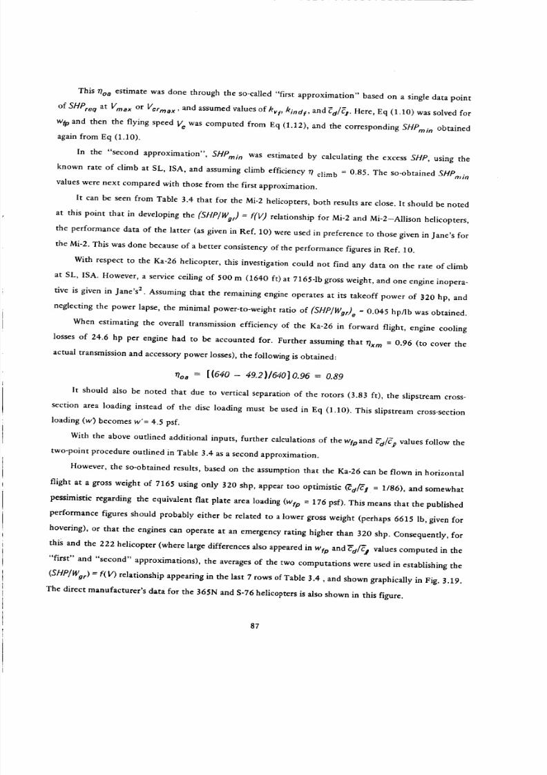
8/3/2019 Stepi Soviet 1
http://slidepdf.com/reader/full/stepi-soviet-1 97/298
This _oa estimate was done through the so-called "first approximation" based on a single data point
of SHPre q at Vma x or Vcrma×, and assumed values of kvf, kindf, and _d/_. Here, Eq (1.10) was solved for
w_ and then the flying speed Ve was computed from Eq (1.12), and the corresponding SHPmi n obtained
again from Eq (1.10).
In the "second approximation", SHPmi n was estimated by calculating the excess SLIP, using the
known rate of climb at SL, ISA, and assuming climb efficiency _7 climb = 0.85. The so-obtained SHProin
values were next compared with those from the first approximation.
It can be seen from Table 3.4 that for the Mi-2 helicopters, both results are close. It should be noted
at this point that in developing the (SHP/Wgr) = f(V) relationship for Mi-2 and Mi-2--Allison helicopters,
the performance data of the latter (as given in Ref. 10) were used in preference to those given in Jane's for
the Mi-2. This was done because of a better consistency of the performance figures in Ref. 10.
With respect to the Ka-26 helicopter, this investigation could not find any data on the rate of climb
at SL, ISA. However, a service ceiling of 500 m (1640 ft) at 7165-1b gross weight, and one engine inopera-
tive is given in Jane's 2. Assuming that the remaining engine operates at its takeoff power of _20 hp, and
neglecting the power lapse, the minimal power-to-weight ratio of (SHP/Wgr) e = 0.045 hp/lb was obtained.
When estimating the overall transmission efficiency of the Ka-26 in forward flight, engine cooling
losses of 24.6 hp per engine had to be accounted for. Further assuming that rlxra = 0.96 (to cover the
actual transmission and accessory power losses), the following is obtained:
rloa = [{640- 49.2)/640]0.96 = 0.89
It should also be noted that due to vertical separation of the rotors (3.83 ft), the slipstream cross-
section area loading instead of the disc loading must be used in Eq (1.10). This slipstream cross-section
loading (w) becomes w'= 4.5 psf.
With the above outlined additional inputs, further calculations of the wfpand _-d/gp values follow the
two-point procedure outlined in Table 3.4 as a second approximation.
However, the so-obtained results, based on the assumption that the Ka-26 can be flown in horizontal
flight at a gross weight of 7165 using only 320 shp, appear too optimistic _d/ff! = 1/86), and somewhat
pessimistic regarding the equivalent flat plate area loading (wtp = 176 psf). This means that the published
performance figures should probably either be related to a lower gross weight (perhaps 6615 lb, given for
hovering), or that the engines can operate at an emergency rating higher than 320 shp. Consequently, for
this and the 222 helicopter (where large differences also appeared in Wfp and_d/_'a_ values computed in the
"first" and "second" approximations), the averages of the two computations were used in establishing the
(SHP]Wgr) = f(V) relationship appearing in the last 7 rows of Table 3.4, and shown graphically in Fig. 3.19.
The direct manufacturer's data for the 365N and S-76 helicopters is also shown in this figure.
87

8/3/2019 Stepi Soviet 1
http://slidepdf.com/reader/full/stepi-soviet-1 98/298
,_1
0.-r'
(3
ELO
Z
0a,,
n,,
n
0.16
0.14
0.12
0.10
0.08
0.08
0.04
BO-105
nv 5114 Ib
Mi-2 & Mi-2-A
7826 Ib
365N
8488 Ib UH-1H /
,_ 9500 Ib //
/
Ka-26
7055 Ib
/
/
222
'850 Ib
S-7610,000
0.02
020 40 60 80 100 120
SPEED OF FLIGHT: KN
140
Figure 3.19 Comparison of shaft horsepower per pound of gross weight vs speed of level flight at SL, ISA
of Soviet and Western helicopters of up to 12,000-1b gross weight class.
88

8/3/2019 Stepi Soviet 1
http://slidepdf.com/reader/full/stepi-soviet-1 99/298
Because of the lower disc loading of Soviet helicopters, the power requirements per pound of gross
weight in the low-speed flight regime are below those of their Western counterparts, as shown in Fig. 3.19.
However, at high speeds, the (SHP/Wgr) values of the Ka-26 helicopters rise sharply because of its relatively
large flat-plate area as witnessed by the level of equivalent flat area loading of wfp _ 200 psf (taken as an
average of the first and second approximations.
The high speed (SHP/War) values of the Mi-2 helicopters are approximately on the same level as for
the UH-1H and BO-105, but are above those of the 365N, 222 and, especially, S-76 helicopters.
With respect to (Wgr/De)max, a glance at this figure would indicate that the Mi-2 helicopters achieve
a maximum gross weight to the equivalent drag ratio of (Wgr/De)ma x _. 4.5, which is one of the highest
for the considered gross-weight class. In contrast to the Mi-2, the Ka-26 represents the lowest level of
about 3.75. Of the Western helicopters, only the S-76 attains a level of (Wgr/De)ma x _ 5.2.
(SHP/War) Values at High Velocities . In Fig. 3.20, the SHP/Wg r values at high V's are shown vs
corresponding speeds. The third-degree parabolas representing the so-called cubic law of power dependence
on speed are also marked in this figure. It is interesting to note that the points for the Mi-2 and UH-1H
helicopters lie on the same parabola, the Ka-26 is above it, while the parabola passing through the S-76
lies well below the other one. Points representing the BO-105, 365N, and 222 are approximately half
way between the two parabolas. This distribution of points reflects the degree of aerodynamic cleanness
as given by the wfp values (see Table 3.4) which, for the S-76 helicopter, reaches 560 psf, while they are
approximately at one-half of that level for Mi-2 and UH-1H helicopters.
3.5 Energy Aspects in Forward Flight
Fuel Requirements per Pound of Gross Weight. The numerical inputs needed for a determination
of fuel requirements per pound of gross weight and one hour; or 100 nautical miles, are shown in Table
3.5. This table was prepared for the gross weights shown in the first row of Table 3.4, and the (SHP/Wgr) --
f(V) values as listed in the last seven rows of that table. All the gross weights considered in Tables 3.4
and 3.5 represent maximum flying weights.
The resulting fuel flow per pound of gross weight and hour for the compared helicopters is shown
in Fig. 3.21. The auxiliary grid in this figure permits one to judge at a glance how those helicopters com-
pare from the point of view of fuel utilization per pound of gross weight and distance flown (selected
here as 100 n.mi). In addition, this fuel consumption per pound of gross weight and 100 n.mi is shown
as a function of flying speed in a separate graph (Fig. 3,22).
89

8/3/2019 Stepi Soviet 1
http://slidepdf.com/reader/full/stepi-soviet-1 100/298
-J
c,)
£0
" Z _
•i '-.\)
"1
\
\
": _--__ w I--
,,, ,,_
_ w
w 0
.I.HOI=IM SSOIdO dO C]NNOd _l::ld dHS
.=o
£.0
O
e-,
O
o_
e-,
o
o
o
e_
o
r,r.
90
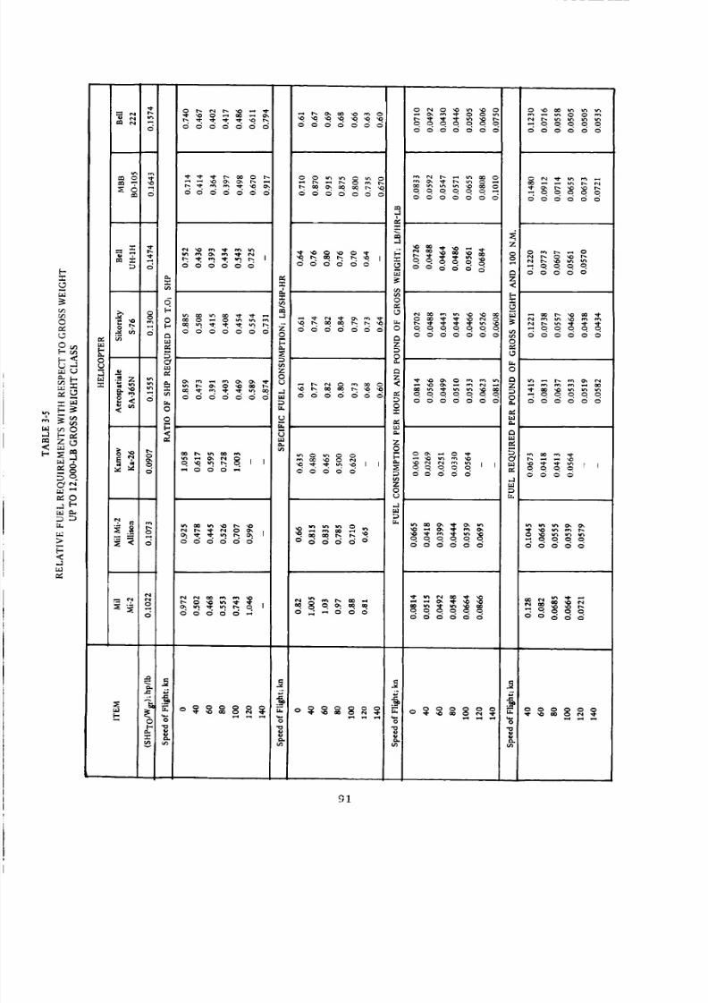
8/3/2019 Stepi Soviet 1
http://slidepdf.com/reader/full/stepi-soviet-1 101/298
0o000oo0 oo000o
0
b9 _. 0
0 m
S5 8_u _o
£_
N
_.i ,. 0
<Mt_
_o ooooooo ooooooo
o o0oo0o o0o0oo
=
m
m Zo
o _
__ ' ' __, ,_000_ 00000
__1000000
o
Ooo_oO
...... _ _oooo_0000000 000000
=
z
_oooooz<
o =
oN6N6oN _ 666NNo_ oz _D0 °
_ 0000000 _00000
o
z _
_ 00000 0000M
z _o Du _
MN
...... _q_000000 00_00
_oooo_ oo_
0 0
[0 _
91

8/3/2019 Stepi Soviet 1
http://slidepdf.com/reader/full/stepi-soviet-1 102/298
M'O :10 8"1_' UnOH El:ld NOIld_nSNO0 "l::lNd
o
o
oo
Zv,
¢:"1-
.Ju.
u.
O
C_
t,j
o
X-
.,.o
e-,
e-
F
"F,iO
O
Q
eL
0
°.
g
92

8/3/2019 Stepi Soviet 1
http://slidepdf.com/reader/full/stepi-soviet-1 103/298
Z
J" _ | | • • g g • e e | g g | •
d d d _ o d o
!W'N 00L-8"1/81 "'!IAI'N 00L _ "M'O -IO91 U3d "13n-i
O
O
O
Zv
8
,-IU.
8 o
uJ
WO.
ON
O
O
"T
O
r-
E
c
93

8/3/2019 Stepi Soviet 1
http://slidepdf.com/reader/full/stepi-soviet-1 104/298
Looking at Figs. 3.21 and 3.22, one would note that the original Mi-2 helicopter shows one of the
higher relative fuel measurements per pound of gross weight with reference to time and distance. Through
installation of the Allison 250-C20B turboshafts, these fuel requirements improve considerably, and in the
low-speed regime become one of the lowest.
The Ka-26 helicopter appears as especially interesting with respect to energy aspects related to pound
of gross weight. It can be seen from these figures that thanks to the reciprocating engines installed in
that helicopter, it becomes a champion as far as low fuel requirements per pound of gross weight with
respect to time and distance are concerned. It should be noted, however, that the optima occur atlow flying
speeds (about 50 and 70 knots, respectively) which, in some operations, may represent a serious drawback
(low productivity).
Fuel Requirements per Pound of Zero-Range Pa;cload. The numerical inputs required for the de-
termination of fuel required per pound of zero-range payload and one hour, and a hypothetical distance
of 100 n.mi. are shown in Table 3.6. As in the preceding case, all calculations are performed for the maxi-
mum flying weight. The results are shown in Figs. 3.23 and 3.24. These figures indicate that when the fuel
consumption is related to the hypothetical zero-range payload, the Mi-2 helicopter shows decisively the
worst energy characteristics of all the compared helicopters. However, through the installation of Allison
engines, these characteristics are approximately on the same level as the Western rotorcraft. The Ka-26
still remains the champion of low energy utilization in the low-speed regimes of flight. It should be empha-
sized at this point that the favorable energy characteristics of the Ka-26 helicopter are achieved at the
maximum flying gross weight, which is not only higher than the VTO gross weight, but even exceeds
the hovering gross weight OGE at SL, ISA. The importance of the influence of increasing the operational
gross weight of a given helicopter with respect to energy aspects related to payload should not be over-
looked.
Fuel Required per Pound of Payload vs Distance. Even approximate values of fuel required to fly
one pound of payload over various distances can provide an important insight regarding energy aspects
of the compared helicopters. Using the approach outlined in Section 1.5, the numerical inputs required
in that evaluation are given in Table 3.7, while the results are graphically presented in Fig. 3.25.
It can be seen from this figure that the Mi-2 with the original engines represents the highest energy
requirements for transportation of a unit weight of payload over any distance. Installation of the Allison
turboshafts leads to considerable improvements, making the fuel requirement practically identical to that
of the BO-105 and 222.
It should be remembered, however, that a change in the ground rules for selecting gross weight (say,
making it equal to the so-called VTO gross weight) may considerably affect the relative position of Soviet
helicopters vs their Western counterparts. This will be especially true in the case of the Ka-26, for the
already mentioned reasons of a large discrepancy between its VTO and maximum flying gross weight.
94

8/3/2019 Stepi Soviet 1
http://slidepdf.com/reader/full/stepi-soviet-1 105/298
000000
e_
<
<0--1
>.<
;,a.1
z_
I0 _
N
0b.,
Z
U
M
e_
oM
©b.,
e_
m
_: o _; ,,,
.._ Z
_ --
<
gg g-- ®
R a =--gg
e_
o z,,..1
< o
o o
N <
_., 0
Z N
o
2: ua
DeL
0 o' c_ o c_ d "_a o o o o
,1 ,.Ila..I
Dt=
_ _ ,2. _ _ _ . ,.., ,., ,.., ,..,
t_
.8
.£
a::
g,
0
E
<
I-
oz
95

8/3/2019 Stepi Soviet 1
http://slidepdf.com/reader/full/stepi-soviet-1 106/298
0.10 "\ /"
20 40 60 80 100 120
SPEED OF FLIGHT: KN
140
Figure 3.23 Fuel required per hour and pound of zero-range payload of Soviet & Western Helicopters
of the up to 12,000-1b gross weight class
96
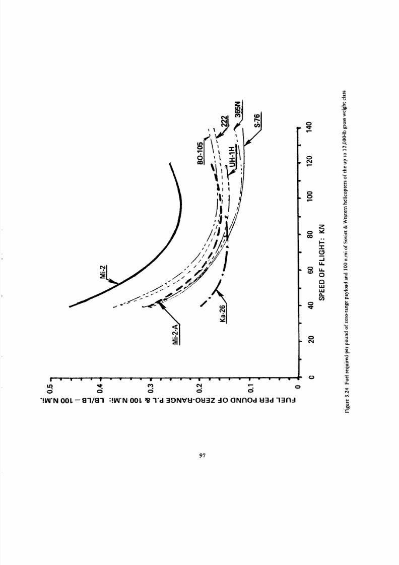
8/3/2019 Stepi Soviet 1
http://slidepdf.com/reader/full/stepi-soviet-1 107/298
0 0
"!IN'N 001. -- 8118"1
o o
:!IN'N 001. • "I'd 3DNVI:I-OI:I3Z 40 CINFIOd 1:13d"13£1-1
O
O¢N
O
¢)CO
8
O
O¢N
¢)
z
"r"C9.Ju.
1.1=
Or_U.II.U
O
C_
e,l
£
-i
O
e_
O
O
O
,'r
O
..i
-I
&
97

8/3/2019 Stepi Soviet 1
http://slidepdf.com/reader/full/stepi-soviet-1 108/298
o ooooo
0m ,.0 c_• _ . .
ooooo
,-1
<
z<[-
D
>U
<
©--1 r._
zg
Od
5
,.-1
r,
"1"
=- g
D m c_ 0 0 0 0 0
o_,!>
D
g _
._Z
_ • _oo
o< _ D 66666
v
_ c
.-_'- _ "=.
D
u_
00000
,__00000
=_, _
o
o__._0000_
_._
o
_ o
Z
ooooo
<
98

8/3/2019 Stepi Soviet 1
http://slidepdf.com/reader/full/stepi-soviet-1 109/298
|
m_1
m._1 OVOIAVd :10 (]NnO¢:l I:l:::ld]3UII1031::I 7311-I
¢)
¢N
o¢)N
i_ "_
Z
_J
¢.)
o1.0
o
r_
er_
99

8/3/2019 Stepi Soviet 1
http://slidepdf.com/reader/full/stepi-soviet-1 110/298
3.6 Productivity
Productivity Index. Productivity index values were computed from Eq (1.17a) for various distances
and flying speeds from 40 knots to Vcrma ×. Auxiliary plots made of PI = f(V) indicated that maximum
productivity occurs at the maximum operational flying speed, which is assumed to be the maximum cruise
speed as listed in published specifications of the compared helicopters. Consequently only the PI values
corresponding to Verma x were computed in Table 3.8, and graphically presented in Fig. 3.26. This figure
indicates that the productivity index of all three Soviet helicopters is below that of their Western counter-
parts; the Mi-2 showing the lowest P1 values. Installation of Allison engines made a considerable improve-
ment in the productivity index, but still failed to make it comparable to an even older Western helicopter
such as the UH-1H.
3.7 General Discussion and Concluding Remarks
The original Mi-2 helicopter appears to have well-selected basic design parameters. However, chiefly
because of the high specific weight and high specific fuel consumption of the GTD-350 turboshaft plus
higher than the Western weight empty to gross weight ratio, the performance of the Mi-2, when referred
to payload, becomes much inferior to that of its Western counterparts (e.g., Figs. 3.23 and 3.24).
Installation of Allison 250-C20B engines considerably improve the energy aspects with respect to gross
weight, but especially to payload, and makes the relative fuel requirements per pound of payload and either
hour or unit of distance similar to that of Western helicopters. Nevertheless, when it comes to the produc-
tivity referred to weight empty, the values of the so-called productivity index, including the Allison version
of the Mi-2 are below those of the Western counterparts.
A comparison of the Mi-2-A and BO-105 helicopters may be of special interest, as both have the same
powerplants, but represent different design philosophies (e.g., disc loading at maximum flying weight of
4.37 psf for the Mi-2-A vs 6.25 psf for the BO-105), resulting in the Mi-2-A being larger, heavier, and with
greater zero-range payload capacity (2689 lb vs 2070 lb), but slower than the BO-105. In spite of the lower
maximum cruise speed of the Mi-2 derivation, because of a higher (Wp/) o, its absolute productivity [ ( Wp/)o
X Verma x] at zero-range would be 303,857 lb-kn/hr vs 273,240 for the BO-105. However, the productivity
index of the Mi-2-A is much lower than for its German counterpart (Fig. 3.26). The hourly fuel consump-
tion per pound of zero-range payload in hover is quite similar for both helicopters. This is also true with
respect to the energy consumed per pound of payload in forward flight (Fig. 3.25).
The Ka-26 represents an interesting departure from the general design philosophy of the entire range
of helicopters having gross weights of up to 12,000 lb; not only because of its coaxial configuration, but
also because of the utilization of reciprocating engines.
100

8/3/2019 Stepi Soviet 1
http://slidepdf.com/reader/full/stepi-soviet-1 111/298
140,91
120
..I
P" 40o
(3O
2O
0
__ 365N
Ka-26 _" "_ -_.
Mi-2-A / "_' "_
Mi-2
i ii
" I_ | ' II I
0 50 100 150 200
DISTANCE: N.Mi.
Figure 3.26 Productivity index at maximum cruise speed of Soviet and Western helicopters
of the 12,0004b gross weight class.
101

8/3/2019 Stepi Soviet 1
http://slidepdf.com/reader/full/stepi-soviet-1 112/298
o0
.a
ee_
<
oq rr
tad
i,i
b- L_ -r
>_..a
C2
e_
e_
-- I
o
6 c_ _c_
LC) CO 0
0 O0
C
_ °°
°°oo
h.l
At first glance one may expect that such a
helicopter would have no chance at all in
competition with turbine-equipped rotorcraft.
However, it appears that in applications requir-
ing low speeds only, this helicopter can find an
operational niche because of its favorable
energy aspects with respect to payload. But
should those applications require hovering at
elevated altitudes and/or ambient temperatures,
the relative advantage of the Ka-26 may dis-
appear.
At this point it should again be empha-
sized that under accepted ground rules, all
comparisons were carried out at gross weights
either equal, or almost equal, to maximum
flying gross weights. All of the compared Soviet
helicopters exhibit a hovering altitude_elevated
temperature performance inferior to that of
their Western counterparts. Consequently,
should the ground rule emphasize the require-
ment of OGE hover at high altitudes and/or
temperatures, then the gross weight of the
Soviet machine used in the comparative study
would go down; resulting in a worsening of
their comparative position with respect to
Western rotorcraft .
102

8/3/2019 Stepi Soviet 1
http://slidepdf.com/reader/full/stepi-soviet-1 113/298
Helicopters of the
Chapter 4
12,000 to 30,O00-1b GW Class
4.1 Basic Data
Three-view drawings of the compared helicopters are shown in Figs 4.1a through 4.1b, while their
principal characteristics are given in Table 4.1.
Of all the compared helicopters, the least is known about the Mi-24-D. However, there are indica-
tions that this rotorcraft represents an evolutionary development of the Mi-8; having similar powerplants
(TV-3-117), although possibly higher rated (to 2170 hp), and apparently having a similar rotor system,
but of smaller radius. There also appear to be some differences in the blade root section, as can be seen
when comparing Figs 4.In and 4.lb. Because of the many uncertainties regarding the Mi-24-D, its char-
acteristics and performance are listed in the last column of Table 4.1.
Some of the data contained in Table 4.1 is graphically presented in Figs 4.2 through 4.7.
Disc Loading (Fig. 4.2). The disc loading of the Mi-8 helicopter is somewhat lower than that of its
modern Western counterparts, but not much different from that of the older CH-3E. By contrast, the
estimated disc loading of the Mi-24-D 2 appears on the same level as that for the UTTAS-type helicopters,
and even higher when the normal gross weights are compared. The disc loading of the Ka-25 is not much
different from the disc loading of the contemporary single-rotor Western helicopters. As for the tandem
configuration - represented here by the CH-46E -- it should be noted that its disc loading based on the
swept area is quite low (w --- 5.7 psf) even at its maximum flying weight of 23,300 lb.
Power Loading (Fig. 4.3). As in the case of the Ka-26 in the up to 12,000 gross weight class, the
power loading of the Ka-25, based on the "official" takeoff SHP, appears the highest of all the compared
helicopters. Since, at this writing, little is known about the characteristics of GTD-3F turboshafts, it is also
unknown whether the thermodynamic capabilities of that engine exceeds its mechanical capabilities. By
contrast, as discussed in Ch. 2, the TV2-117A turboshafts have higher thermodynamic than mechanical
capabilities. It is also known that under record-establishing conditions 2 the TV-3-117 engines operate at
ratings of 2200 cv (metric horsepower), which is approximately equal to 2170 hp. Consequently, when
these higher thermodynamic capabilities for the Mi-8, and higher ratings of the Mi-24-D engines are taken
into account, the power loading of the Mi-8 would be closer to its Western counterparts, and that of the
Mi-24-D would be on the level of the U.S. UTTAS machines.
103

8/3/2019 Stepi Soviet 1
http://slidepdf.com/reader/full/stepi-soviet-1 114/298
(a) 'Hip-C' military version of Mil Mi-8 twin-turbine helicopter, with additional side view (bottom) of
commercial version (Pilot Press ).
(b) Mil Mi-24 assault helicopter, in the form known to NATO as 'Hind-A', with original tail rotor (Pilot Press).
Figure 4.1 Three-view drawings of Soviet and Western helicopters of 12,000 to 30,O00-1b GW class.
104

8/3/2019 Stepi Soviet 1
http://slidepdf.com/reader/full/stepi-soviet-1 115/298
(c) 'Hormone-A' anti-submarine version of the Kamov Ka-25 helicopter. Scrap view shows option of bl isters
at base of central tail-fin (Pilo t Press) .
(d) Aerospatiale SA 330 Puma transport helicopter (Pilot Press).
Figure 4.1 Three-view drawings of Soviet and Western helicopters of 12,000 to 30,000-1b GW class. (Cont'd).
105

8/3/2019 Stepi Soviet 1
http://slidepdf.com/reader/full/stepi-soviet-1 116/298
_, l.------6a'OIA.
I
•,
(e) S ikorsky CH-3E twin-turbine engine transport helicopter.
(f) Boeing Vertol CH46E (Sea Knight) combat assault helicopter.
Figure 4.1 Three-view drawings of Soviet and Western helicopters of 12,000 to 30,O00-1b GW class. (Cont'd)
106

8/3/2019 Stepi Soviet 1
http://slidepdf.com/reader/full/stepi-soviet-1 117/298
(g) Boeing Vertol YUH-61A Utility Tactical Transport Aircraft System (UTTAS) (Pilot Press).
(h) Sikorsky UH-60A Black Hawk combat assault helicopter (Pilot Press).
Figure 4.1 Three-view drawings of Soviet and Western helicopters of 12,000 to 30,O00-lb GW class
107
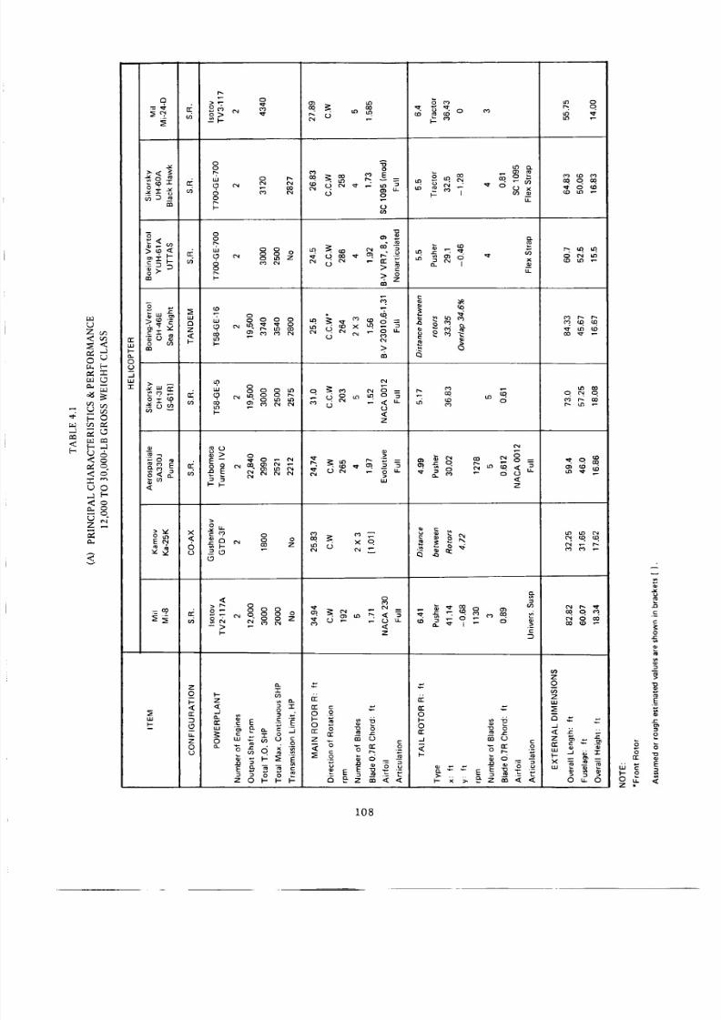
8/3/2019 Stepi Soviet 1
http://slidepdf.com/reader/full/stepi-soviet-1 118/298
Z_
r_
<
-- ,.m
3
0
=4-
m
-6
.ED
130
El
_°5_
ill
_m
v _
=a?
#
co
d
o
o
oo
RI.-
8bku 0 0
R
w
-_, oo
_ O°oOoOo
F-
l-
z
_J
2
o
"N
o
Z
82_
e,i o coco _.o
z
0
i,M
_E
_1
0 u. 0 o_
.E
£
E
108
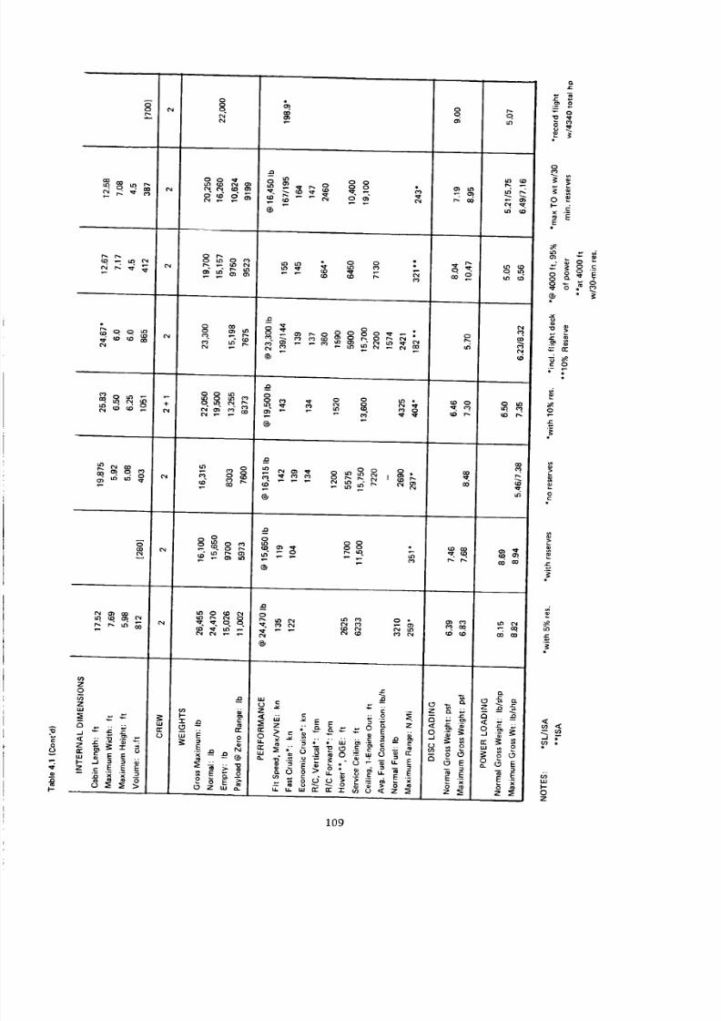
8/3/2019 Stepi Soviet 1
http://slidepdf.com/reader/full/stepi-soviet-1 119/298
o
Z
0
uJ
A r_ '"
-- E E
0o
o.
O_0_o_
o
8_
uJ o
N
_ _ 0W _
_' 8 88
@
o
@
®
@
x_
@
@
J_
.. ,, _ g _
r-.
CO CO
.-_ " _ _9 '_ -.I
0
o
_'_
,.2
0
F
r,
g
w
I-
0
Z
109
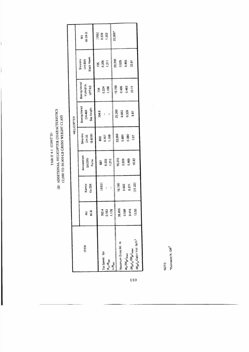
8/3/2019 Stepi Soviet 1
http://slidepdf.com/reader/full/stepi-soviet-1 120/298
,e (J
J
v
,'7
m
_n
o{0
..J
_m
E _,
w
p-
r. e! _ o
r_
Z
E
0 wz •
11o
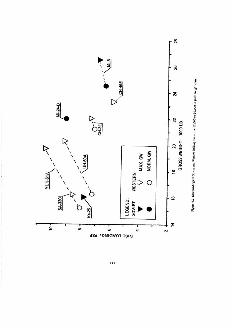
8/3/2019 Stepi Soviet 1
http://slidepdf.com/reader/full/stepi-soviet-1 121/298
\
\
\
\
\
\ \\ \
\ \
\ \
-ISd :E)NIQV01 OSIQ
0
C_0
0
0
0
.=
0:/3
_o
'd-
111

8/3/2019 Stepi Soviet 1
http://slidepdf.com/reader/full/stepi-soviet-1 122/298
__ o__I> o _
,-I_j ii
_ O;, _o
\ \\
__o.--_
_,_-----_
_--_,,_, _1\ _\ =1
\
\ \%\ \
_.l_ _ _',• _ E)
| I II | | I
o 0o (.D
dHS/g'l :E)NI(]V01 ld:lMOd
(N
CO
_0
_1
"1"f3
iii
ft')¢/)o
E:
£
"T'
0
0
£
0
.__0
ffl
0
&
112

8/3/2019 Stepi Soviet 1
http://slidepdf.com/reader/full/stepi-soviet-1 123/298
Main Rotor Tip Speed (Fig. 4.4). The main rotor tip speed of the Mi-8 helicopter appears on the same
level as that of the Western rotorcraft of the same gross weight class (about 700 fps). There is no data avail-
able to this writer regarding the tip speed of the Mi-24-D, but it is probably close to that of the Mi-8; thus
V t _ 700 fps is assumed for the Mi-24-D. For the Ka-25, V t = 650 fps is postulated.
Tail-Rotor to Main-Rotor Radii Ratio and Relative Tail-Rotor Distance (Fig. 4.5). In general, the
tail-rotor to main-rotor radii ratio of the Soviet helicopters and their Western counterparts are of similar
magnitudes; with the Mi-24-D showing the highest values of that ratio: (Rtr/Rmr) = 0.229.
The relative distances CZ) of all the compared helicopters appear to quite uniformly within the limits
1.176 _< x'_< 1.305 with the lowest value represented by the Mi-8 and the highest by the Mi-24-D.
Weight Empty and Zero-Range Payload to Gross Weight Ratios (Fig. 4.6). The weight ratios shown
in Fig. 4.6 are related to the maximum flying gross weight. A glance at this figure indicates that the weight-
empty and zero-range payload to gross weight ratios of the Mi-8 helicopter roughly represent an average of
the Western counterparts; while for the Ka-25 those ratios are close to the extremes of the Western designs
in spite of the fact that the considered version of the Kamov helicopter represents the crane configuration.
The CH-46E appears to exhibit the least favorable (We/Wgr) and (Wpl)o/Wg r ratios of all the compared
helicopters of the 12,000 to 30,0004b gross weight class. However, it should be emphasized at this point
that the CH-46E is the only one of the compared rotorcraft that is equipped with automatic blade folding
and other special equipment which is counted as weight empty. For instance, for the CH-46D, (We/War) =
13,067/23,000 = 0.568 and (WplJo/Wg r = 0.413.
Cabin Volume Loading at Zero-Range Payload (Fig. 4.7). Similar to the preceding gross weight
group, the Mil Mi-8 helicopter appears to have provisions of larger cabin volume with respect to maximum
payload than the Kamov Ka-25 design. In comparison with the Western helicopters, the relative roominess
of the Ka-25 is on practically the same level as the UTTAS class, while the cabin of the Mi-8 appears slightly
less spacious with respect to maximum payload weight than that of the CH-3E and CH-46E, but more
spacious than that of the UTTAS helicopters.
4.2 Hovering and Vertical Climb Aspects
Table 4.2. Similar to the procedure established in Ch. 3, the first estimates of FMoa in Table 4.2 were
performed using the primary data related to maximum gross weights contained in Table 4.1. In the second
estimate, computations were performed using the best hovering data available related to gross weights.
First, the figures of merit for all helicopters except the YUH-61A and SA-330J were estimated using
Fig. 1.16 as a basis, and deviations from that relationship due to such factors as airfoil sections and Reynolds
numbers were also estimated. The influence of the rotor solidity was computed with the help of Eq. (1.26a).
For the Y UH-61A, Fig. 1.16 obviously represents the tower-tested and established FM m r = f(_ n ) relation-
ship, while the manufacturer's figure was used for the SA-330J.
113

8/3/2019 Stepi Soviet 1
http://slidepdf.com/reader/full/stepi-soviet-1 124/298
|
00
!
00r_
Sd-I
I
0(D
:0:13d8 dll 1:10101:1
GON
N
CO
OOI.O
00.-I
OO
I.U
Ore
u_
..o
C_e_
O
e_
8
F
C_
u
114
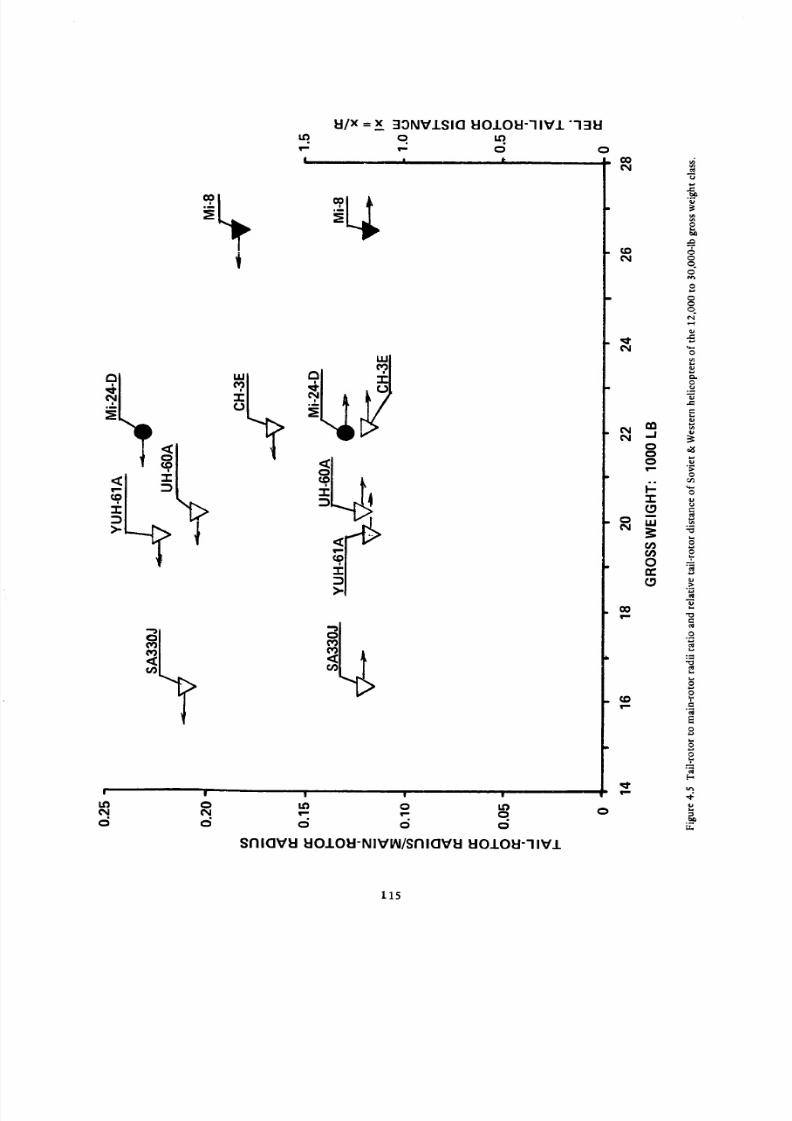
8/3/2019 Stepi Soviet 1
http://slidepdf.com/reader/full/stepi-soviet-1 125/298
TI |
LO 0
o d
l:I/XX 33NVJ.SIO EIO.LOEI-"IIV.I. "-131::1=.q. q m.
I | I-
| | |
I.o o I.Ov,-- _ 0
d d o
Snl0VEI tlOIOEI-NIVIN/SnlOVI:I I:IOIOEI--IIV1
o
00N
¢.oN
ooo
"1-¢3
t_
ore
co
¢,D
_J
e_
oO
O
=.O
:=
O
E
-g
'd"
115

8/3/2019 Stepi Soviet 1
http://slidepdf.com/reader/full/stepi-soviet-1 126/298
|
O
O
I
.LHOI::IM SSOUO
OVOqAVd BONVU-OUBZ
0 0
I I I I
iii
>.
|
1
O
IHOI3M SSOUO/AId_3 IHOI3M
O
CO
¢,O(N
nn,..J
'N OC_O
-r"(,O
I,,I.I
On,,,
(.9
00
(,o
c_
O
C_
C_
C_
o(.q
..g
Or_
O
.o
O
,q.
u.
116

8/3/2019 Stepi Soviet 1
http://slidepdf.com/reader/full/stepi-soviet-1 127/298
_r
1,1,1
O
8
8
8°.
Eg
Q
m
g'va
N
%
.g
z4"no/a_ :E)NlaVO-I 31/_13-1OA NISYO
117

8/3/2019 Stepi Soviet 1
http://slidepdf.com/reader/full/stepi-soviet-1 128/298
,..a
<
_, -,- oi3 D
-8
.- X? _
g>
o
...I
,.-1 0 m
r,.) _
z_ _,<
Z o
o ! o
=co g
._.1
-r
u_
orr
_9
dg_o6_
_ °o°
_gogggg&d_qg°6_
_g=_gggg
o _ °°°oo_
__o_OO
_°_°o_
o
.-- LL
8 i: -
rr
0
to
g F._ _. _g
o _
o
o_ _
_o_O_o
0 -_rr
j
_ _" o_
"3
g
5-
o_
0
Z
118

8/3/2019 Stepi Soviet 1
http://slidepdf.com/reader/full/stepi-soviet-1 129/298
o o
d (5
o - o0
o _ _ _ _ o
_ 0 Q
_ _ Cr_ 0
o o
6 6 _ _6 (5 6 _ _ I0
• _ . _ . _ _ . I o
0
uJ
0
m _ - E E
_ -
119
tr
Z u_ u.
o_ ._- ® . _ '_

8/3/2019 Stepi Soviet 1
http://slidepdf.com/reader/full/stepi-soviet-1 130/298
Sincet wasdifficultto establishaluesof all theparametershichcouldinfluencehetail-rotor
figuresof meritlevels,t wasdecidedo assumecommonalueof FMtr = 0.6 for all single-rotor heli-
copters. It is believed that this approach is justified by the fact that possible practical deviations from the
assumed figures of merit level would have little influence on the results of the comparative rating of the
helicopters studied.
The overall power transmission efficiency (Boa) for the single-rotor helicopters was computed from
Eq. (1.27), assuming rlxrntot = 0.96, which would cover the actual transmission and accessory losses. For
the coaxial configuration of the Ka-25, Boa = 0.95 was assumed, while for the tandem represented by the
CH-46E, the Boa = 0.92 value included the overlap losses (Bop = 0.95).
As in Ch. 3, the overall figure of merit values computed by the step-by-step procedure are compared
either with those deduced from the hovering ceiling data or those obtained from flight test results. In the
first case, an average of the step-by-step and hovering ceiling results are shown in Table 4.2 as "official"
FMoa values. In the second case, the values computed from flight test data were assumed to be correct,
while the closeness of the step-by-step obtained FMoa'S to those resulting from flight tests seems to
strengthen one's confidence in the established procedure (see CH-46E, UH-60A, and YUH-61A).
It should be added at this point that the gross weight-rotor thrust relationship from which the FMoa
of the CH-46 was computed [FMoa ='SHPid/(RHP/rTxm )] is shown in Fig. 4.8.
Having the FMoa values established, the VTO gross weight was computed from Eq. (1.2), and the
vertical R/C at SL, ISA was calculated from Eq. (1.9).
Power per Pound of Gross Weight in Comparison with the Ideal Power (Fig. 4.9). Based on the so-
called civilian rating of 1500 SHP of the TV2-117A turboshaft, the ratio of the maximum and normal
gross weights for the Mi-8 helicopter appears to be lower than for its Western counterparts. By contrast,
the power ratio for the Mi-24D with TV3-117 engines rated at 2170 hp would be on the Western level.
The [(SHPTo) o [( Wor)ma x ] [ [SHPid/(Wor)ma x ] ratio for the Ka-25 helicopter appears to be the lowest
of all the compared helicopters of this gross weight class (about 1.5). Whether the assumed rating of the
GTO-3 engine of (SHPTo) o -- 900 hp is routinely exceeded is not known.
It should be noted that such recent Western helicopter designs as the SA330J, UH-60A, and YUH-61A
exhibit, at normal gross weight, a power ratio of about 2.5 (based on transmission-limited power), and
about 1.75 at the maximum flying gross weight.
Average Blade Lift Coefficient (or CTIO) in Hover OGE at SL_ ISA (Fig. 4.10). Similar to the pre-
viously discussed gross weight class, the majority of the Soviet helicopters depicted here also appear to
operate in hover OGE, even at SL, 1SA, at higher average blade-lift coefficients then their Western counter-
parts. However, in the Mi-24D, the _¢ value (at least at NGW and assumed Ii"t = 700 fps) appears to be closer
to those of the older Western rotorcraft, but is still above those of the UTTAS and Puma (later developed
into the so-called European UTTAS-Super Puma) types.
120

8/3/2019 Stepi Soviet 1
http://slidepdf.com/reader/full/stepi-soviet-1 131/298
B'I O00t-_l _-_--_ i _-9"q..913_ SSOUe O_uua:13U
121
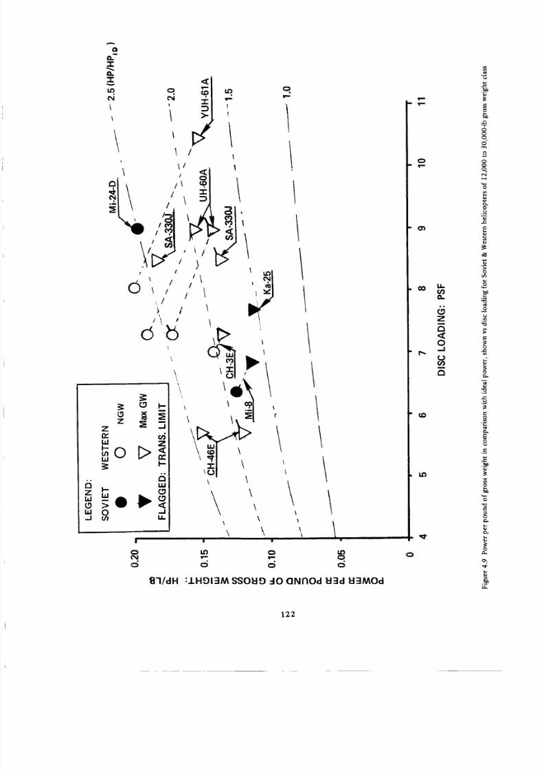
8/3/2019 Stepi Soviet 1
http://slidepdf.com/reader/full/stepi-soviet-1 132/298
A
o
"r
I,D
_! /
//
/,.
p /
_ / / I/\ / / t
z _ __Z
W
_oD_UJ I_
_ _o t_,_
\\
\,
!
0
m
.!
\ \
\\
\ \i
I i
U'J 0 _
'B'I/dH :IHOI::IM SSOHO dO C]NFIOd H:ld H-dMOd
C_
O')
_O
I.O
IL
O..
L_Z
0.J
o
8
._.
ea
N
e_
e,
0
e_
.__
122

8/3/2019 Stepi Soviet 1
http://slidepdf.com/reader/full/stepi-soviet-1 133/298
z
ill
,--O_ILl
' _ _ _-• I_
I
• J ; w , • ' 'v
1N::II01-,n=n300 1-.11"1::IC]V"IB 30VI::I:IAV
V' 1
I"" _ '_ q O O O
"('_1
"r"
nil
o ore
ID
to
o
o
,,D
o
I=
<:
o
,,,D
<
r=
123
8/3/2019 Stepi Soviet 1
http://slidepdf.com/reader/full/stepi-soviet-1 134/298
Main Rotor Figures of Merit (Fig. 4.11). As previously mentioned, the main rotor figure of merit
of the YUH-61A helicopter was computed from tower test data s. The FMmr value was supplied by the
manufacturer for the SA330J, while for all other helicopters the values were estimated. A glance at Fig.
4.11 indicates that the Mi-8 probably exhibits the lowest FMmr of the whole group, while that of the
Mi-24D has the potential of attaining the same level as the UTTAS-Puma type. The FMmr of the Ka-25
would probably be higher than for the CH-3E, but below the UTTAS type.
Tail-Rotor Thrust to Gross Weight and Power to Rotor-Power Ratios (Fig. 4.12). It can be seen from
Fig. 4.12 that in hover OGE at SL, ISA, all of the compared single-rotor helicopters of the presently inves-
tigated gross weight class exhibit surprisingly uniform tail-rotor thrust to gross weight ratios of Ttr/Wg r
0.076.
With respect to the power ratios, the Mi-8 with RPtr/RPmr _ 0.12 at Wgrmax is on the same level as
Western helicopters having the same type of operational gross weight. The Mi-24D appears to exhibit the
lowest power ratio of approximately 0.10, but it is emphasized that this occurs at the assumed normal
gross weight and furthermore, that all inputs on this helicopter are (at this writing) highly speculative.
Overall Figure of Merit (Fig. 4.13). The overall figures of merit for the YUH-61A, UH-60A, and
CH-46E helicopters were obtained from flight test results (Refs. 8 and 12, and Fig. 4.8); for the other com-
pared helicopters, the FMoa values were estimated. Fig. 4.13 shows that the Ka-25 probably has the highest
overall figure of merit because of its coaxial configuration. The UTTAS and Puma, but especially the
UTTAS represent the next highest FMoa level. The Mi-8 and CH-3E appear on the same level, while the
Mi-24D is on a somewhat higher level.
VTO Gross Weight. The lapse rate of takeoff power at 3000-ft altitide, ISA, was read from Fig. 2.10
and the engine power available at that altitude was computed. The obtained values were then compared
with the transmission limits and the lower of the two powers was used in calculating the VTO gross weight
from Eq. (1.2) for single-rotor helicopters. For the tandem configuration, a constant coefficient of 20.22
was used in Eq. (1.2) instead of 16.05. The so-calculated VTO gross weight values are listed in Table 4.2,
which shows that for the SA330J and CH-46E, the VTO gross weights are higher than their maximum gross
weights, while for the CH-3E and YUH-61A they are lower, and for the UH-60A the weights are equal. The
VTO gross weights for the Mi-8 and Ka-25 are even lower than even their normal gross weights. This is in
contrast to the Mi-24-D where the VTO gross weight is much higher than the assumed normal gross weight.
Vertical Rates of Climb at SL, ISA (Fig. 4.14) . Using the VTO gross weights, as well as the maximum
flying and normal gross weights, the corresponding vertical rates of climb at SL, ISA were computed for the
compared helicopters. The results are shown in Table 4.2, and plotted in Fig. 4.14.
A glance at this figure indicates that the vertical rate of climb of the TV2-117A-equipped Mi-8
helicopter at its VTO gross weight is very low. This is due to the character of the lapse-rate curve of this
124

8/3/2019 Stepi Soviet 1
http://slidepdf.com/reader/full/stepi-soviet-1 135/298
I
LO
"-e
I-- uJ
I--OZ
o
co
co('41
(_1
co
f.o
i
If) o LOCD r,O I.O
111:131N-IO 31:IFIOI:I I:IOIOU NIVIN
0O-I
"I-
raI.LI
(/)O
E:¢3
,.O
'7"
C_
,-4
.,...
,<
L_O
O
.1=
i,
125

8/3/2019 Stepi Soviet 1
http://slidepdf.com/reader/full/stepi-soviet-1 136/298
11
0£N
O
IHOI3M SSOI:IO/ISflklH.L I:IO..LO_I-'I IV.I.
tO _ If)
c_ o o
I i I
0
{/)
,-I
c
I-0Z
I._ Q 1.0
d d o
l:::l :lMOd I::IOIOI::I-NlVl/_/I:I:IMOd I:10101::1--IlVl
126
0oN
N
(N
coT'--
Q
111.J
OOO
/:-v
N
UJ
C/)
Oe_
e_
o
<
Ot_
O
.o
O
O
o
Oe_

8/3/2019 Stepi Soviet 1
http://slidepdf.com/reader/full/stepi-soviet-1 137/298
IDfDc5
I
i \
'7 \\
"I"6tDCD
z***
w •
o
Lo
IlEI31N -IO 3EIngl=l -I"IVU3AO
CD
,q.
I:0--I
On,,.CD
cD
8
e,
o
go
4
127

8/3/2019 Stepi Soviet 1
http://slidepdf.com/reader/full/stepi-soviet-1 138/298
_t>o<q
-J
./
/
//
N
/
.¢' d,¢
<r.--I/ (-_
f/
/
/d
o
0 0 0 0 00 0 0 00 LO 0 I_
IAIdd :fllAIIlO dO 31VU I'_:)I/I:I:JA
..(3
u
o
¢b¢b
c_
S
e_
o
o
o
6[-,
<
>
.,Y.
128

8/3/2019 Stepi Soviet 1
http://slidepdf.com/reader/full/stepi-soviet-1 139/298
engine - showing an increase of power with altitude (up to about 4000 ft). For rotorcraft having trans-
mission-limited takeoff power, the vertical rates of climb at the VTO gross weight are also low (Vvc m.
200 fpm).
With respect to Soviet helicopters, it should be noted that the Mi-8 and Ka-25 at SL, ISA have no
vertical climb capability at either their maximum or normal gross weights, By contrast, the TV3-117-
equipped Mi-24D at its assumed normal gross weight would have a vertical climb capability similar to that
of the UTTAS types at their normal gross weights.
With the exception of the CH-3E, all of the compared Western helicopters show some vertical climb
capability at their maximum flying weights. The UTTAS-type helicopters show very high rates of climb at
their normal gross weights.
4.3 Energy Aspects in Hover
Table 4.3. The most important inputs required in the study of energy aspects in hover, as well as
numerical values of hourly fuel consumption per pound of gross weight and zero-time payload are indi-
cated in Table 4.3.
For all of the Western helicopters, with the exception of the CH-3E, the calculations were performed
at maximum gross weights since, at these flying weights, they have not only OGE capabilities at SL, ISA,
but also at 3000-ft altitude (definition of the VTO gross weight).
By contrast, the Soviet Mi-8 and Ka-26 helicopters at their maximum gross weights can not hover at
SL, ISA (at least at the accepted "civilian" ratings of the TV2-117A engines). Consequently, the VTO gross
weights for these two helicopters were taken as a basis for the comparative study of energy aspects in hover
performed in Table 4.3. For the Mi-24-D, the fuel required per pound of gross weight and one hour was
computed at its normal gross weight, assuming the same sfc variation as for the TV2-117A engine.
The results of these studies are graphically presented in Figs. 4.15 and 4.16.
Hourly Fuel Consumption per Pound of Gross Weight in Hover OGE at SL_ ISA (Fig. 4.15). It can
be seen from Fig. 4.15 that the Soviet Mi-24-D and Ka-25, and the Western SA330J helicopters show
the highest fuel consumption per unit of gross weight in the hover regime of flight. It should be noted
however, that an error may be present in the estimates of the lb/hr-lb values of the Ka-25 and Mi-24-D
helicopters since, at this writing, no "official" data for the fuel consumption of the GTD-3F and TV3-117
turboshafts were available.
In spite of the somewhat inferior sfc of the TV2-117A engine, the Mi-8 appears to have a good fuel
consumption per unit of gross weight.
The T700-GE-700-equipped UTTAS helicopters exhibit the lowest lb/hr-lb values of the entire group.
129
8/3/2019 Stepi Soviet 1
http://slidepdf.com/reader/full/stepi-soviet-1 140/298
[-
0
_'E- _o
. LU
>
o_
zo
0,v [.
0
o : o
.._ m
_ D o 6 _ _ 6 d 6 0_ 6 6 d d ,d
-8
< *
._ __ _ o _ _ o o o°. _ o c_ o o o_n
'_ _ _ om
00
L °o _ _ o o o _ • _ _ - .
6 _o o ooo
k-
_ _ _- d _ ° o o _, _ . . . _. _.
m
o
-_ o_ __p0_
._ _ _: = -_,: _._ = u__ E _o ._ _:
0 oo _,_ "1" N
UJ
I--
0
Z
_ .=_.
_ E.__ N
g e
130

8/3/2019 Stepi Soviet 1
http://slidepdf.com/reader/full/stepi-soviet-1 141/298
v-- 0 0 0 _
BI-UH/BI
0
:ME) 40 B-I U::ld NOI.I.dlAInSNO0 -131"1::1II:IFIOH
00t'N
_N
tN
CN(N
C_tN
¢0
eD
_n--I
O
"1-
(.9
u.I
_)(/)
Onr
(.9
d
.o
,.Q
¢)(D
o.¢)e_
o
o
eL
8
2:r.
T,O
Jc/)
©
O
b_
0
0
e_
0
4
.._
131

8/3/2019 Stepi Soviet 1
http://slidepdf.com/reader/full/stepi-soviet-1 142/298
Fuel Consumption per Pound of Payload in Hover OGE, SL, ISA (Fig. 4.16). Unfortunately, there
is insufficient data regarding the Mi-24-D helicopter to include it in this comparison. As far as the other two
Soviet helicopters are concerned, the Ka-25 appears to have a higher fuel consumption per unit weight of
payload (based on the assumed sfc) than its Western counterparts, with the exception of the CH-3E. The
Mi-8 also shows slightly higher fuel requirements per unit weight of payload than those of the CH-46E and
SA330J helicopters. The UTTAS-type helicopters, due to the low sfc of their engines and favorable struc-
tural weight aspects, exhibit by far the lowest fuel requirements with respect to payload of all the com-
pared helicopters. It should once more be pointed out that should the CH-46 be configured for land opera-
tions, as are the rest of the compared rotorcraft, its relative fuel consumption referred to payload would
be lower.
0.40
0.30
0
0.20
oo
D 0.10u.
>...Jfl:
0-I-
0
/ f
CH-3E ..- i i _/"
CH-46E
_. YUH.61.Ak_
..........
0
J • Iw
20 40 60
HOVER TIME: MINUTES
Figure 4.16 Variation with time of hourly fuel consumption per pound of maximum payload in hover OGE, SL, ISA
for Soviet and Western helicopters of the 12,000 to 30,O00-1bgross weight class.
132
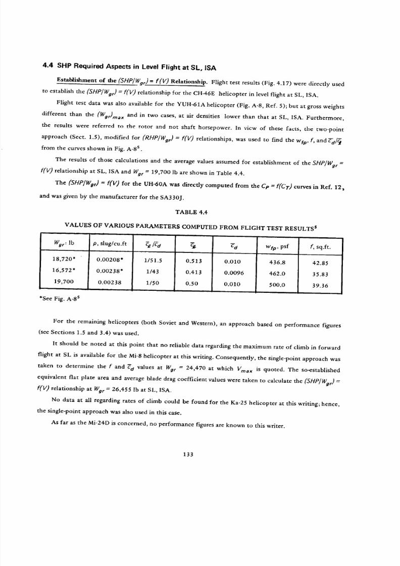
8/3/2019 Stepi Soviet 1
http://slidepdf.com/reader/full/stepi-soviet-1 143/298
4.4 SHP Required Aspects in Level Flight at SL, ISA
Establishment of the (SHP/Wgr) = f(V) Relationship. Flight test results (Fig. 4.17) were directly used
to establish the (SHP]Wg r) = f(V) relationship for the CH-46E helicopter in level flight at SL, ISA.
Flight test data was also available for the YUH-61A helicopter (Fig. A-8, Ref. 5); but at gross weights
different than the (Wgr)ma x and in two cases, at air densities lower than that at SL, ISA. Furthermore,
the results were referred to the rotor and not shaft horsepower. In vicw of these facts, the two-point
approach (Sect. 1.5), modified for (RHP/Wgr) = F(V) relationships, was used to find the wfp, f, and F-a/_
from the curves shown in Fig. A-8 s .
The results of those calculations and the average values assumed for establishment of the SHP/Wg r =
f(V) relationship at SL, ISA and Wg r = 19,700 lb are shown in Table 4.4.
The (SHP/Wgr) = f(V) for the UH-60A was directly computed from the Cp = F(CT) curves in Ref. 12,
and was given by the manufacturer for the SA330J.
TABLE 4.4
VALUES OF VARIOUS PARAMETERS COMPUTED FROM FLIGHT TEST RESULTS s
War: lb
18,720"
16,572"
19,700
*See Fig. A-8 s
p, slug/cu.ft
0.00208*
0.00238*
0.00238
va
436.8
462.0
500.0
1/51.5
1/43
1/50
0.513
0.413
0.50
0.010
0.0096
0.010
w_,psf f, sq.ft.
42.85
35.83
39.36
For the remaining helicopters (both Soviet and Western), an approach based on performance figures
(see Sections 1.5 and 3.4) was used.
It should be noted at this point that no reliable data regarding the maximum rate of climb in forward
flight at SL is available for the Mi-8 helicopter at this writing. Consequently, the single-point approach was
taken to determine the f and Fd values at We r = 24,470 at which Vma x is quoted. The so-established
equivalent fiat plate area and average blade drag coefficient values were taken to calculate the (SHP/Wg r) --
F(V) relationship at Wg r -- 26,455 lb at SL, ISA.
No data at all regarding rates of climb Could be found for the Ka-25 helicopter at this writing; hence,
the single-point approach was also used in this case.
As far as the Mi-24D is concerned, no performance figures are known to this writer.
133

8/3/2019 Stepi Soviet 1
http://slidepdf.com/reader/full/stepi-soviet-1 144/298
2800
2600
VNR
2400
2200
2000W
0
W
O 1800
1600
1400
1200
1000 _
40 60 80 100 120 140 160
TRUE AIRSPEED: KN
Figure 4.17 SHP = f(V) relationship in level flight at SL, ISA for the CH-46E helicopter. (Courtesy of Boeing Vertol Co.)
134

8/3/2019 Stepi Soviet 1
http://slidepdf.com/reader/full/stepi-soviet-1 145/298
The computations indicated in Table 4.5 as the 1st Approximation were performed for the SA330J
using manufacturer's figures regarding the SHP required at 134 knots. Then, taking advantage of the (SHP/Wg r)
= f(V) relationship, the two-point technique was used to determine the wtp, f, and _d values shown in the
2rid Approximation.
In the 1st Approximation for the UH-60A, the single-point results produced a (SHP/Wg r) = f(V) rela-
tionship very close to those based on flight tests 12. Then using the manufacturer's figures for SHP required at
155 knots, and SHPmin, the two-point technique was used to determine the wto, t, and_ a values shown in the
2nd Approximation.
In the case of the CH-3E helicopter, the two-point approach was applied in the calculations of fand C-d
at Wg r = 21,247 lb, and the results were used to establish the (SHP/Wg r) = f(V) curve at Wgr = 22,050 lb at
SL, ISA.
All of the above-described calculations are indicated in Table 4.5, and the results are graphically shown
in Fig. 4.18.
Fig. 4.18. A glance at Fig. 4.18 indicates that similar to the up-to-12,000-1b gross weight class, the Kamov
helicopter shows the lowest power per pound of gross weight requirements in the low-speed range of level
flight at SL, ISA. However, as the flying speed becomes higher than 70 kn, the SHP/(Wgr)ma x requirements
begin to increase quite sharply.
The Mi-8 helicopter appears to exhibit generally good characteristics with respect to the SHP/(Wgr)ma x
= f(V) relationship. It also appears that this helicopter, together with the SA330J and CH-3E show the highest
gross weight to equivalent drag ratios (approximately 4.4).
It is also noted that, in general, all of the SHP/(Wgr)ma x --- f(V) curves for the compared helicopters
in this gross weight class are included within a relatively narrow band. It should be recalled that for the CH-46E,
UH-60A, and YUH-61A helicopters, the results shown in Fig. 4.18 were based on flight tests. The (SHP/Wg r) =
f(V) curve for the SA330J represents a fit into the points representing the manufacturer's SHP/Wg r and V
values shown in Table 4.5. The curves for all of the other helicopters were deduced from published perform-
ance figures; keeping in mind the uncertainties as to a precise knowledge of engine power at the quoted speed
of flight, and the rate of climb values in forward flight.
(SHP/Wgr) Values at Vma x . In Fig. 4.19, the SHP/Wgr values at Vma x or Vcrma x are shown vs corre-
sponding speeds. The third-degree parabolas representing the so-called cubic law of power dependence on speed
are also marked in this figure. It is interesting to note that the points for the YUH-61A, UH-60A and SA330J
helicopters lie on the same parabola. Another parabola passes through the point representing the Ka-25 heli-
copter. The Mi-8 point lies close to the lower parabola. It should also be noted that, contrary to Fig. 3.20, the
scatter of points in the 12,000 to 30,000-1b gross weight class appears much smaller than for the previously
considered gross weight class of up to 12,000 lb.
135
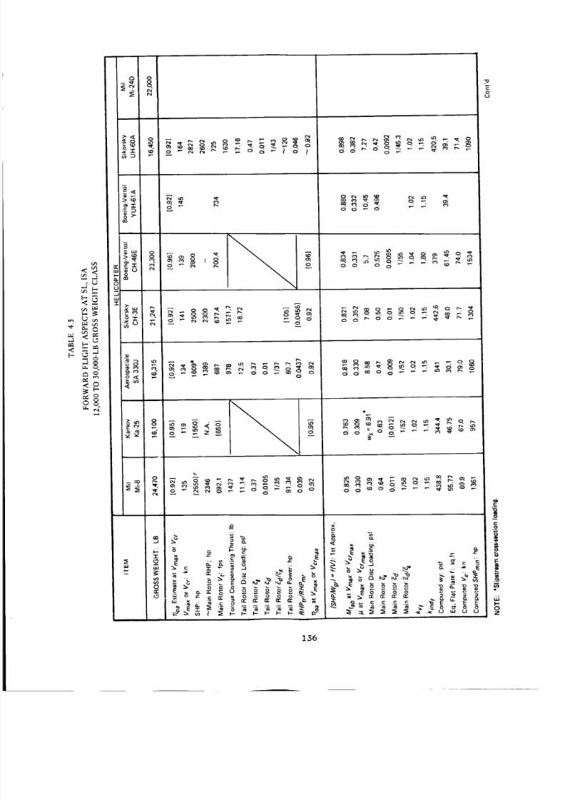
8/3/2019 Stepi Soviet 1
http://slidepdf.com/reader/full/stepi-soviet-1 146/298
Q 0-- "_t 0
_2 q
_ o
m
o
z
0
< _ "r
< e
m_ r,gm
o_ _ .
'8r_ o oo Oo _ _
IO
o!.
o
ddff _
w
o _ =_oooooo .....
_ _ _ = _- ® _ _ _ _ _ _
_ 0 "
0
" _ _ _ ,e,_,_ _- _ ,.-
o
o
E
uJ
0
Z
136

8/3/2019 Stepi Soviet 1
http://slidepdf.com/reader/full/stepi-soviet-1 147/298
A
"0
q.
I--
0oo. ._.
0
m _ _ ¢£ _ c_ c_ o o o o"_. _. .... "_.0 _ 0 0 0 0 0 0 0
• o _c___o_o ._o6 6
_00_
0000000
___'0000000
m
_ 00000000
000000
0000000
Eo " "
¢.,
h-
0
Z
137

8/3/2019 Stepi Soviet 1
http://slidepdf.com/reader/full/stepi-soviet-1 148/298
0.16
0.14YUH-61A
_v//
SA330J
UH-60A
CH-46E
0.02
0
0 20 40 60 80 100 120
SPEED OF FLIGHT: KN
140
Figure 4.18 Comparison of shaft horsepower per pound of gross weight vs speed of level flight at SL, ISA
of Soviet and Western helicopters of the 12.000 to 30,000-1b gross weight class.
138

8/3/2019 Stepi Soviet 1
http://slidepdf.com/reader/full/stepi-soviet-1 149/298
F
o
o
• _l.
\
\.
w _lw Z
z _
L_
ffl
L
c;
81/dH
| w
o L_,-- o.
:J.HDI:JM b"SOI::ID-IO QNNOd U3d dHS
D
,-4
c/)
:E
oc_l
o
o
o
_a_6oo0t_
c
o0o
8
c
o
c
e,
4
139

8/3/2019 Stepi Soviet 1
http://slidepdf.com/reader/full/stepi-soviet-1 150/298
4.5 Energy Aspects in Level Flight at SL, ISA
Fuel Required per Pound of Gross Weight in Level Flight at SL, ISA. The numerical inputs needed
for determination of fuel required per pound of gross weight and one hour, or pound of gross weight and
100 n.mi in level flight at SL, ISA are shown in Table 4.6. It should be noted that at this writing, there
was no data available to the investigators regarding the sfc of the GTD-3 engines installed in the Ka-25
helicopter, nor the performance figures necessary for determination of the (SHP/Wg r) = f(V) curves of the
Mi-24D helicopter. Consequently, for these two helicopters, no fuel requirements in forward flight could
be determined at this time.
It should also be emphasized that all considerations of energy aspects of all the compared helicopters
were performed at their maximum flying weight.
The resulting fuel flow per pound of gross weight and hour for the compared helicopters is shown in
Fig. 4.20. The auxiliary grid in this figure permits one to judge at a glance how these helicopters compare
from the point of view of fuel utilization per pound of their gross weight and distance flown (selected here
as 100 n.mi). In addition, this fuel consumption per pound of gross weight and 100 n.mi is shown as a func-
tion of flying speed in Fig. 4.21.
Looking at Figs. 4.20 and 4.21, one would note that the fuel consumption of the Mi-8 helicopter
per pound of gross weight and hour, and pound of gross weight and 100 n.mi. is very similar to that of
the CH-46E and CH-3E helicopters. Furthermore, it appears better than that of the SA330J, and is only
inferior to the latest U.S. UTTAS helicopters (YUH-61A and UH-60A). It should also be pointed out that
for the Super-Puma equipped with the Makila engine, the relative fuel consumption figures are approxi-
mately 15 to 20 percent better than for the SA330J.
Fuel Requirements per Pound of Zero-Range Payload. The numerical inputs required for the determina-
tion of fuel required per pound of zero-range payload and one hour, and a hypothetical distance of 100
n.mi. are shown in Table 4.7. As in the preceding case, all calculations are performed for the maximum
flying weight . The results are shown in Figs. 4.22 and 4.23.
A glance at these figures would indicate that when the fuel consumption is related to the hypothet ical
zero-range payload, the Mi-8 helicopter shows one of the best energy characteristics of all the compared
helicopters, and is surpassed only by the UTTAS types.
However, it should be recalled at this point that although the present comparison is carried out on
the common basis of maximum flying weight, the Mi-8 and the CH-3E at their gross weights do not have
OGE hover capabilities (Fig. 4.14). In order to get a better balanced picture, the fuel requirements should
be recalculated and compared; say, for the VTO gross weight. In the case of the CH-3E and especially, the
CH-46E helicopters , some special equipment is incorporated into the weight empty, thus leading to low
(Wp/)o/Wg r ratios. Here, again, a revision of the weight empty values of these two helicopters might be
desired.
140

8/3/2019 Stepi Soviet 1
http://slidepdf.com/reader/full/stepi-soviet-1 151/298
•"F "i.
_ o
-8
.- o
°o_ _ 0
o
'_ "_ mm 034_0
.1
_q
,,, _,,_[-,
M
o
0000000 OOOOOOO
ooooooo ooooooo
m
B e
O
O
Z
O O
B __ o
_ dg6_gd_
_OOOOO
_OOOOO_ OOOOOOO
ooqqqqqOOOOOOO
_OOOOO
Ooo_oo
I--
o o o o o o o _ _ o o o o o_ _, _0,_ _ _
O 7
L9 I--
(5
OOO OOO O _0 _ O_
_ or
0 Z
OOO OOOO e0 00 _D I/'_ 1,0 ID !
_- NodNd_ o _: NNN_Nd
m (j7
qq qqqqq _qqo_qoo ooooo oooo oO
ILl
I"-
g0
_F
I,I.
g
I'-
O
141

8/3/2019 Stepi Soviet 1
http://slidepdf.com/reader/full/stepi-soviet-1 152/298
\\
MO :10 Bq • ldH I:l:Jd NOIJ.dlNNSNO0 "1::11")-I
o
.,D"T'O
o
8o
8n_o
e.:
o
<r._
,J
_u
.=.
_Jo
o
a
o
0
142

8/3/2019 Stepi Soviet 1
http://slidepdf.com/reader/full/stepi-soviet-1 153/298
LI.J UJ
I
I!!
I
I
/I
/
I
I
/
/
I
/ i
/
/
/
/
• • • II • I • • | j • | • • | • •
!IAI'N 00L-81"1/8"1 :'!IAI'N 00L • ME) =10 QN('IOd EI3d "13f1=1
o
O
oc'_
oo
Z
"I-
I,.I.,
1,4.
o
I.IJ
crJ
o
oN
o
0
q
O
q
8
E
>0
<
0
0
143

8/3/2019 Stepi Soviet 1
http://slidepdf.com/reader/full/stepi-soviet-1 154/298
<
<0,.4
>,
<
6_
u
m _
E.-©z b.,
_ q
U
M
r,,.
o
J
0
m
_w
o
<
_d
_6
_6
_ 6
_6
<o
>.
Z
<
oft.w
N
0
if2
<
gQ-1"
ff.
_J
.5
0
.J
o666ddd
0000000
000000
Z
00
__000000
<o
<
oddoodo ,o
N
Z
0
Z
v
"r
..J
o
I.U
0000000 Z
o
Z
v
#-r
.JU-
LLI
LU
dd6dd6d
ooo
6ddddd
oododd
o000oo
o 0 o 0 o 0
P.
0
E
<
I.-0Z
144

8/3/2019 Stepi Soviet 1
http://slidepdf.com/reader/full/stepi-soviet-1 155/298
0
\
\ \
\
8"1-1:1H/8"I :ld 3ONVI:I-OH3Z dO (]NrlOd • 81"IOH 1:13d O31:111"1031:1 131"1d
8
Z
"1-
-II.I.
I.i.
O
¢3I.UU.Ia.
£
..o
OO
ff_
£O
.¢
.=
O
<
O
o
'S
C
#0
C
0
g
g
N
145

8/3/2019 Stepi Soviet 1
http://slidepdf.com/reader/full/stepi-soviet-1 156/298
r,!l
o
!IN'N 00L-8"1/8"1 :!IAI'N OOL • Id 30NVI:I-O_I3Z dO ONl'lOd tdgd 13nd
o(%1
oo
z
o= -,-u
-ILL
LL
0
l.IJuJ
o.,
o
oN
o
0
e.,
0
oC,
e_
oC,
0
o.
.C
E
0
<r_
f/2
C_
o
o
:20
146

8/3/2019 Stepi Soviet 1
http://slidepdf.com/reader/full/stepi-soviet-1 157/298
Fuel Required per Pound of Payload vs Distance. Using the approach outlined in Sect. 1.5 and applied
in Sect. 3.5 for helicopters in the up to 12,000-1b gross weight class, the numerical inputs required in that
evaluation are given in Table 4.8, while the results are graphically presented in Fig. 4.24.
It can be seen from this figure that in contrast to the original Mi-2 (Fig. 3.25), the Mi-8 represents one
of the lowest energy requirements for transportation of a unit weight of payload over any distance; sur-
passed only by the U.S. UTTAS type helicopters.
Remarks made in the preceding subsection regarding the gross weight basis for comparison (WOrma x vs
Wgrvfo), as well as observations about unfavorable results of the type of weight-empty bookkeeping of
the CH-46E and CH-3E helicopters also apply to the comparison shown in Fig. 4.24.
4.6 Productivity
Productivity Index. The inputs necessary to calculate the productivity index from Eq (1.17a) are
indicated in Table 4.9. However, in light of the experience gained in Sect. 3.6, the PI evaluation in this
case was limited to the specified maximum cruise speed only. The so-obtained P1 values are listed in Table
4.9, and graphically presented in Fig. 4.25. A glance at this figure would indicate that the productivity
index of the Mi-8 is below that of the UTTAS types and the SA-330J; but above that of the CH-46E and
CH-3E.
4.7 General Discussion and Concluding Remarks
At this writing, an indepth discussion of design aspects of Soviet helicopters of the 12,000 to 30,000-
lb gross weight class must, unfortunately, be limited to the Mi-8 helicopter only, since there is a lack of
engine characteristics for the Ka-25 engine, and incomplete data on weights and performance of the Mi-24D
helicopter.
However, on the basis of the presently available limited information, the following general remarks can
be made with respect to the latter two rotorcraft.
Similar to the Ka-26 helicopter discussed in the preceding chapter, the Ka-25 appears to be under-
powered by Western standards, resulting in limited hovering and vertical climb capabilities. Consequently,
its VTO gross weight of 15,300 lb is below its maximum flying weight of 16,100 lb. Again, similar to the
Ka-26, the same design philosophy is visible in the case of the Ka-25: take advantage of the coaxial con-
figuration and derive as much performance as possible from the limited power installed in the rotorcraft.
Therefore, although its average blade lift coefficient may be favorable for a high rotor figure of merit in
hover, it appears to be too high to provide a comfortable margin for maneuvers, especially at elevated alti-
tudes and ambient temperatures_ The power required per pound of gross weight in forward flight appears
one of the lowest in the low-speed region (V < 70 kn), but grows rapidly at higher flying speeds, due to low
wfp values. Lack of engine data unfortunately prevents any discussion of energy aspects in all regimes of
flight. 147

8/3/2019 Stepi Soviet 1
http://slidepdf.com/reader/full/stepi-soviet-1 158/298
o_,._ -r
oo do6od
ao
_d
a_
<
h,
Ld
Z<
- <
<
< --
<
Z o
o_2
-1
0
.,J
-6
>,_ _
g>
= "r
_m
b3
m
o
= m
_D 0
00
o
_3.<0.J>.<
Oz
¢rw
121w
0
.../w
i.i.
00000
._m_00000
00000
00000
00000
00
o _
c_ N :_
_ou. _ o
z
LU(JZ
1--00
_3
148

8/3/2019 Stepi Soviet 1
http://slidepdf.com/reader/full/stepi-soviet-1 159/298
\
• \
I.I.I
\
o
8"IIB'I:'lddO B-Il:13dG31:IIFIO:II:II=11"I=I
oI.oN
oON
oI.O
Z
G,i
?.nm
r_
oI.O
O
Q
..o_5
oC_
e_
0
.<
,q-
149

8/3/2019 Stepi Soviet 1
http://slidepdf.com/reader/full/stepi-soviet-1 160/298
a
_D
<__ <
4 < 0
> o
e 8
-5
_w
_ - _ o
o
Ill
, o o _ o.
Ill
I-
¢¢
m
_.1
, _ o
_,_ _,_ _s _
00
. _I" O.
_ N d 6 _ o
z
_.1
'_ _
I--
X
I.-
>
0
0
0
• s o o
_ u_
o
0
Z
150

8/3/2019 Stepi Soviet 1
http://slidepdf.com/reader/full/stepi-soviet-1 161/298
150
m, 100
Q
Z
V-.
¢J
aOeleP,
0
__--""-- ___ UH 60A
-'-"-- Mi-8
-_-- _ "_CH-3E
CH-46E/
| ii • •
0 50 100 150 200
FLIGHT DISTANCE: N.Mi
Figure 4.25 Productivity index at Vcrmax, SL, ISA vs flight distance for Soviet & Western
helicopters of the 12,000 to 30,O00-1b gross weight class.
From the limited information available, it appears that the design philosophy of the Mi-24D is more
in line with current Western trends, as reflected in the UTTAS types. Its estimated disc loading of w = 9
psf at normal gross weight represents a departure from w -- 6.39 psf of the Mi-8 at its normal gross weight.
Consequently, the rotor solidity of the Mi-24D (o _ 0.09) becomes closer to that of the UTTAS types and
the Puma (o = 0.0821 to 0.101).
Unfortunately, the tip speed of the Mi-24D is not known to these investigators, but it is probably at
least slightly higher than the Vt = 692.1 fps of the Mi-8. The higher solidity and higher tip speed should
result in lower average blade lift coefficients (in spite of the higher disc loading) than those of the Mi-8
or Ka-25.
The TV3-117 turboshaft installed in the Mi-24D helicopters has a rating of 2170 hp, which is much
higher than the SHPTo = 1480 rating of the Mi-8 engines. Consequently, the power loading of the Mi-24D
should be similar to that of the UTTAS types.
With respect to aerodynamic characteristics, the Mi-8 helicopter appears quite similar to the CH-3E,
although the Mi-8 disc loading is slightly lower and the power loading (based on the "civil ian" engine
rating) is somewhat higher than that of the CH-3E. The (SHP/Wgr)ma x = f(V) for both helicopters are
quite similar in spite of the disc loading differences. This is also true with respect to the fuel required per
pound of gross weight and hour, and pound of gross weight and 100 n.mi.
151

8/3/2019 Stepi Soviet 1
http://slidepdf.com/reader/full/stepi-soviet-1 162/298
When comparing the energy aspects of the two helicopters, one would note that the hourly fuel con-
sumption per pound of zero-time payload of both helicopters is quite similar. However, in forward flight,
(probably due to the weight-empty bookkeeping of the CH-3E), the energy aspects per pound of zero-
range payload of the Mi-8 appear somewhat superior to those of the CH-3E.
In general, it may be stated that when comparing the basic design aspects of the Mi-8 helicopter with
its Western counterparts, in many respects the Soviet machine appears to be on the same level as its Western
counterparts, seemingly being only inferior to the UTTAS types.
The only area where the Mi-8 is probably inferior is in its hovering OGE and vertical climb capabilities
at its maximum or even normal gross weights. However, it should be noted that this inferiority stems
chiefly from the high power loading based on the "civilian" rating of the TV2-117A engines. Should a
higher rating be permitted in some operations, then the VTO performance aspects of the Mi-8 would
improve.
152
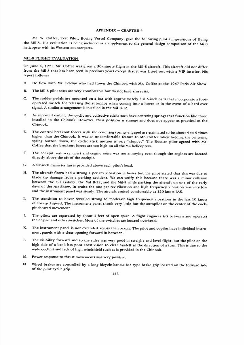
8/3/2019 Stepi Soviet 1
http://slidepdf.com/reader/full/stepi-soviet-1 163/298
APPENDIX-CHAPTER 4
Mr. W. Coffee, Test Pilot, Boeing Vertol Company, gave the following pilot's impressions of flying
the Mil-8. His evaluation is being included as a supplement to the general design comparison of the Mi-8
helicopter with its Western counterparts.
MIL-8 FLIGHT EVALUATION
On June 4, 1971, Mr. Coffee was given a 30-minute flight in the Mil-8 aircraft. This aircraft did not differ
from the Mil-8 that has been seen in previous years except that it was fitted out with a VIP interior. His
report follows:
A. He flew with Mr. Pelevin who had flown the Chinook with Mr. Coffee at the 1967 Paris Air Show.
B. The Mil-8 pilot seats are very comfortable but do not have arm rests.
C.
The rudder pedals are mounted on a bar with approximately 3 X 5-inch pads that incorporate a foot-
operated switch for releasing the autopilot when coming into a hover or in the event of a hard-over
signal. A similar arrangement is installed in the Mil B-12.
D As reported earlier, the cyclic and collective sticks each have centering springs that function like those
installed in the Chinook. However, their position is strange and does not appear as practical as the
Chinook.
E. The control breakout forces with the centering springs engaged are estimated to be about 4 to 5 times
higher than the Chinook. It was an uncomfortable feature to Mr. Coffee when holding the centering
spring button down, the cyclic stick motion is very "sloppy." The Russian pilot agreed with Mr.
Coffee that the breakout forces are too high on all the Mil helicopters.
F The cockpit was very quiet and engine noise was not annoying even though the engines are located
directly above the aft of the cockpit.
G. A six-inch diameter fan is provided above each pilot's head.
H. The aircraft flown had a strong 1 per rev vibration in hover but the pilot stated that this was due to
blade tip damage from a parking accident. We can verify this because there was a minor collision
between the C-5 Galaxy, the Mil B-12, and the Mil-8 while parking the aircraft on one of the early
days of the Air Show. In cruise the one per rev vibration and high frequency vibration was very low
and the instrument panel was steady. The aircraft cruised comfortably at 120 knots IAS.
The transition to hover revealed strong to moderate high frequency vibrations in the last 10 knots
of forward speed. The instrument panel shook very little but the autopilot on the center of the cock-
pit showed movement.
J. The pilots are separated by about 3 feet of open space. A flight engineer sits between and operatesthe engine and other switches. Most of the switches are located overhead.
K. The instrument panel is not extended across the cockpit. The pilot and copilot have individual instru-
ment panels with a clear opening forward in between.
L The visibility forward and to the sides was very good in straight and level flight, but the pilot on the
high side of a bank has poor cross vision to clear himself in the direction of a turn. This is due to the
wide cockpit and lack of high windshield such as is provided in the Chinook.
M. Power response to thrust movements was very positive.
N.
Wheel brakes are controlled by a long bicycle handle bar type brake grip located on the forward side
of the pilot cyclic grlp.
153

8/3/2019 Stepi Soviet 1
http://slidepdf.com/reader/full/stepi-soviet-1 164/298
Chapter 5
30,000 to 100,000-1b GW Helicopters
5.1 Hypothetical Helicopters
Selection of Models for Comparison. An analysis of the hypothetical helicopters discussed by
Tishchenko, et al 1 should provide an additional insight into the current design philosophy of what
is probably the most important group of Soviet rotary-wing designers. Types and configurations
which emerge as being the most successful from the comparative study discussed in Ref. 1 would
most likely serve as conceptual "prototypes" for current or near-future design efforts of the former
Mil group.
Within a study of the 12 to 24 metric-ton gross weight helicopters presented in pp. 129 to 134
of Ref. 1, only single-rotor and tandem configurations were examined, and the conclusion was reached
that under the accepted ground rules, the single-rotor helicopters were superior to the tandems.
This decision clearly indicates the preference of the Tishchenko design team for single-rotor
configurations. Consequently, only this type of configuration was selected to represent the hypo-
thetical helicopters in this comparative study.
With respect to size, it appeared advantageous to select two helicopters; one being close to the
lower, and another close to the upper limit of the gross weight scale. For a 15 metric-ton helicopter,
there is a detailed weight statement included in Ref. 1, which makes this rotorcraft especially suitable
to represent the lowergross weight in
the current comparative study.The 24
metric-ton helicopter
was selected as another representative of the 12 to 24 metric-ton gross weight class.
All single-rotor helicopters of that weight class are of the twin-engine type and are configured
similarly to the Mi-8 (Fig. 5.1c) and the Mi-6 (Fig. 5.1a), while the dimensions of their cargo compart-
ments are approximately 2 X 2 X 8 m.
The performance requirements for all the considered helicopters at their nominal gross weights
are (p. 1171):
Hovering ceiling H h = 1500m _ 4900 ft.
Service ceil ing Hs = 4500m _ 14,750 ft.
Range _ = 370km _ 200n.mi.
At 500m, Vma x = 250 to 300 km/h _ 135 to 162 kn. Later in Ref. 1 when various rotary-wing
configurations are compared, a fast cruise speed of 260 km/hr (about 140 kn) is mentioned for the
pure hypothetical helicopters. On this basis, it will be assumed here that the speed requirement is
Vcrma x = 140 kn.
154

8/3/2019 Stepi Soviet 1
http://slidepdf.com/reader/full/stepi-soviet-1 165/298
x'b Q
(a) MIIRary version of Mil Mi-6 heavy general-I_arpose hollcoplw' (!_I!ol Pr_._)
oooee
(b) NIII Mi-lO flying crane derivative of the Mi-6, with additional side view (bottom) of MblOK (Pilot IJ_ru)
Figure 5.1 Three-view drawings of Soviet and Western helicopters of the 30,000 to 1OO,000-1b GW class
155
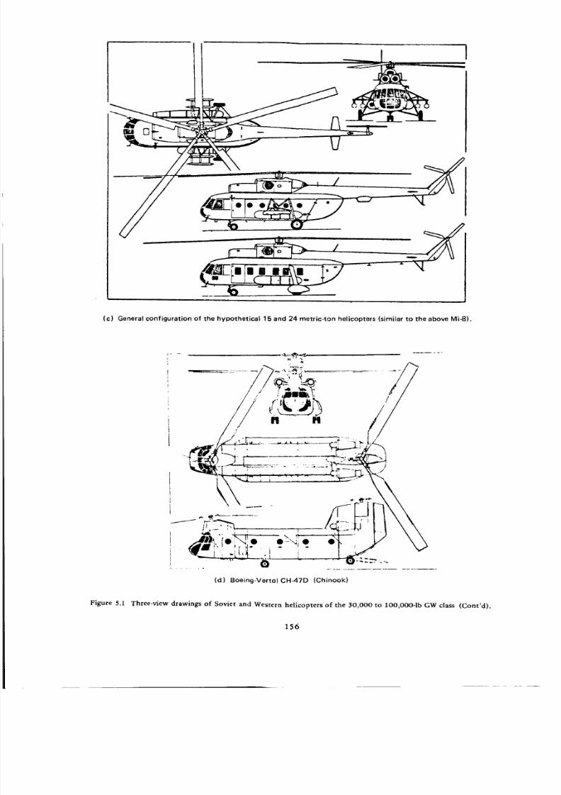
8/3/2019 Stepi Soviet 1
http://slidepdf.com/reader/full/stepi-soviet-1 166/298
(c) General configuration of the hypothetical 15 and 24 metric-ton helicopters (similar to the above Mi-8).
(d) Boeing-Vertol CH-47D (Chinook)
Figure 5.1 Three-view drawings of Soviet and Western helicopters of the 30,000 to lO0,O00-1b GW class (Cont'd).
156

8/3/2019 Stepi Soviet 1
http://slidepdf.com/reader/full/stepi-soviet-1 167/298
0 5 10
SCALE
_,----- 1,_I§FT ---I- t
MAIN ROTOR DA'I" A
OISC ARF.A IOgl t3G _QFT
SL. AO E AREA( I"OI "AL. ) 374 _2 _S0 I T
I_.AOE S_CT_ON NACA _ _OO
BLAOE Cm_ORD 2e 0 INC M
MAml ROTO_ OEAM RAT_0 73G5
72 23FT
,
I
"" ' ' 56i_l'r (l lVi.ONilBLAOIEiJ,'#OI.IDIO) \///
. _:;_04 eT'( OVEmkLL L[NOtM ) U ._ - "''I .
,/ \
W' (.. _-> iT" _',"
01I¢IUITIVl IlIANCIMINT
(e) Sikorsky CH-53D AssaultTransport Marine Helicopter
Figure 5.1 Three-view drawings of Soviet and Western helicopters of the 30,000 to lO0,OO0-1b GW class (Cont'd) .
157

8/3/2019 Stepi Soviet 1
http://slidepdf.com/reader/full/stepi-soviet-1 168/298
• ii
o_-A
(f) SikorskyCH-53E heavy-duty multi-purpc_sehelicopter (Pi!o; Prc_st
Figure 5.1 Three-view drawings of Soviet and Western helicopters of the 30,000 to lOO,O00-1b GW class
In view of the above given high performance requirements, the specified gross weights (15 and
24 m.ton) of the hypothetical helicopters should be considered as normal rather than maximum
flying weights.
Other important characteristics of the hypothetical helicopters are:
Tip speed
Blade thrust coefficient (SL, ISA)
Crew of 3 at 90 kg
V r = 220m/s -_ 720fps.
tvo=0.155, orE_o= 0.465
198.5 lb each.
The weight and powerplant aspects of the two hypothetical helicopters are discussed later.
15 Metric-Ton Helicopter. A detailed weight breakdown for this helicopter is given in Table
2.81 ; but later in the text, it is stated that in the actual comparative study, an increase of 10 percent
in structural weight was assumed. Taking this fact into account, the weight empty of the 15 metric-
ton helicopter becomes We = 8180 kg _ 18,040 lb instead of 7490 kg _ 16,515 lb, while the pay-
load for a 370-km range is reduced from Wol370 = 5890 kg _ 12,990 lb to W0137 o = 5100 kg
11,245 lb. The so-obtained payload checks well with that given in Fig. 2.731 . Consequently, We --
18040 lb is entered in Table 5.1, while the resulting zero-range payload becomes (Wo/) o = 33,075 -
18,040 - 595.5 - 39.5 = 14,400 lb.
On the basis of Figs. 2.71, 2.72, and 2.731, a seven-bladed rotor of Rmr --- 10.25 m = 33.63 ft
is assumed as assuring a maximum payload capacity of Wpl 370 ---- 5100 kg. With the assumed SL, ISA
blade lift coefficient of T0 o = 0.465, the resulting main-rotor blade chord would be Cmr = 1.47 ft,
and Omr = 0.0974.
158

8/3/2019 Stepi Soviet 1
http://slidepdf.com/reader/full/stepi-soviet-1 169/298
Theso-calledeferredower installed (TO power at 500m ISA) can be estimated from the
assumed engine installed weight of 790 kg, and a weight coefficient of 0.140 kg/hpref: SHPre ¢ =
790/0.140 = 5642.9 hp. This would correspond to (SHPTO)o = 5880, or (SHPTo)o = 2940 hp per
engine in SI units, and 2900 hp in British units.
24 Metric-Ton Helicopter. Similar to the above-discussed case, the weight empty of the 24
metric-ton helicopter is deduced using an optimal payload (Fig. 2.711 ) of Iqo/_ 70 = 9400 kg, assum-
ing the weight of fuel to increase proportionally to gross weight from Wfu = 1450 kg for the 15-ton
helicopter to W¢u = 2320 kg for the 24-ton helicopter, and taking the crew weight at Werew = 270
kg. This results in We = 12,010 kg -_ 26,480 lb, while the zero-range payload becomes 25,800 lb.
It is estimated from Fig. 2.71 that the main-rotor diameter should be D = 24.8 (Rrn r = 40.68 ft);
have 7 blades and, as before, operate at SL, ISA at "c¢o = 0.465, which would require a blade chord
of Cmr = 1.94 ft; resulting in a solidity ratio of Ornr -- 0.1065.
Fig. 2.631 can be interpreted that flat-rated engines (with constant power up to 2000 m altitude)
are visualized for transport helicopters. The so-interpreted installed power per kg of gross weight
amounts to Neng _ 0.39 hp/kg, which would result in the total takeoff power installed: SHPTo =
0.39 X 24,000 --- 9360 hp in SI units, or SHPTo _ 9230 hp; i.e., 4615 hp per engine in British units.
Normal rated power is estimated to amount to 92 percent of the takeoff value; i.e., SHPn.rat.
8490 hp.
5.2 Basic Data
Three-view drawings of the compared helicopters are shown in Fig. 5.1a through 5.1f. It should be
noted at this point that in Fig. 5.1c the three-view drawing of the Mi-8 is reproduced, since this aircraft
is supposed to most closely represent the base configuration of the hypothetical 15 and 24 metric-ton
helicopters.
The principal characteristics of the compared helicopters are given in Table 5.1, while some of the
data contained therein is graphically presented in Figs. 5.2 through 5.7.
Disc Loading (Fig. 5.2). It can be seen from this figure that the real Soviet helicopters (Mi-6 and
Mi-10) of the considered gross weight class have a maximum disc loading no higher than about 9 psf. The
design trend of the future, as is probably evidenced by the design optimization process of the hypothetical
helicopters, seems to indicate only moderate increases in disc loading in the next generation of Soviet
single-rotor helicopters in the 12 to 24 metric-ton gross weight class.
In contrast to the Soviet approach, the disc loading of the CH-53E is much higher, as it reaches w =
15 psf at the maximum flying weight (probably the highest value of all presently flying transport heli-
copters).
159

8/3/2019 Stepi Soviet 1
http://slidepdf.com/reader/full/stepi-soviet-1 170/298
Z _4<£_8
Z _
<o
_S
_0 E c_
M_
m
rr
I" I"
--_0 rr _ ko O
Z
0
rrus D
i,
Z
0
0
A
00
' o o
6
Zo_
< a. _ "r_J
,,, .__ • ._,,,{ s8 _
_ _ I-: _ '_
==oS_Z 0 I.- I-- I-
"1"
_.o o.
"I-
0
__oO_"r
Z
_>__x _
0
"I"
"1"
112
"1"
n
rC o _ _ >Lo _ E
-rn
_4 o 00 3::"
>
"1"
Err
0 =
.9
o_ _g0 "o 0
'S 'S_ o- .-
.g - g
_s_ _.o
Z
0
g_ o_z__. . o
_ Z
o
r- _ _ m
c_ _ o
..{3
0
n-
O
I'-
0
re
,,,.,.I
0
i
. e-
q _._ 'a0") I_ _1 0
u-
_ r_ ,_
q q m.
_n
Z
0
Z
121
0 " 0 . *
160
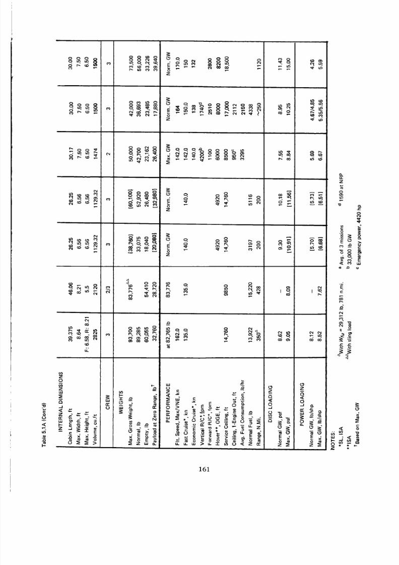
8/3/2019 Stepi Soviet 1
http://slidepdf.com/reader/full/stepi-soviet-1 171/298
0
0
,<
Ld
I-
0 0 0 0
d_g m
Pl
00_
_o 8o ° o
Z
8oo_o oo.r.,--._
Z
Z
.oo
Z
O
o. o _ _ o
<_ 0 0
r,. _I" r,.
t_ 113 t_
O
('N
Z
O
Z --
rr _ _
..I 0 IT
_.. -
z3 _" e__.-
-= .
O
P_ L_ LO 0_ 0_
_ M m _ -m
g
o __o
_o _o_-,
_m_ ze
d _ M_
_o _
z
0
°g
rr"
Z
00_,to
"o o.
0
o _"_ o
r_
r_
II
ff._
4
161

8/3/2019 Stepi Soviet 1
http://slidepdf.com/reader/full/stepi-soviet-1 172/298
_d
m_
_oP_
<
W
Lf_
o±
,o
-6
_o
>_
0
"_ 0
"1"
o
"I-
v
-- 0
.=o
_o _0 I I0 0
o_0q ¢_
! !
| !
I !
O_oo_'. • e0 ,A
e_
_'_ C_ ¢'_ 0
_o°_
0q
0 _" •
_o_r- _ . ._c_ _ o"0
o %I- --
> .a
z_
162

8/3/2019 Stepi Soviet 1
http://slidepdf.com/reader/full/stepi-soviet-1 173/298
Z
,.,.,_ ©--
LU
.-I
\
\
\
\
-_/ ,/
+,l+,+
|
o
|
I,o
dSd :9NI(]VO'! OSIC]
- ot'-
- o03
o¢0
o
oLo
o¢1"
o03
o
m.-I
ooo
/.:
w
N
NO
2
e_
og
0
e_
e_
Q
_o
163
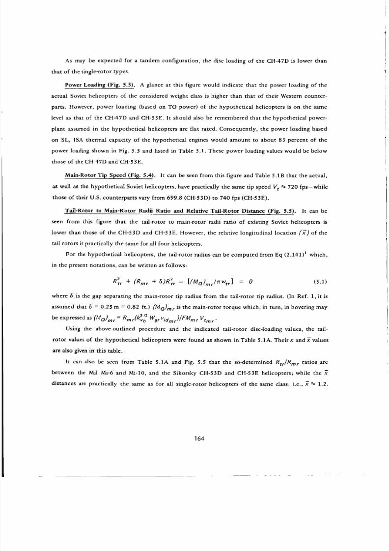
8/3/2019 Stepi Soviet 1
http://slidepdf.com/reader/full/stepi-soviet-1 174/298
As may be expected for a tandem configuration, the disc loading of the CH-47D is lower than
that of the single-rotor types.
Power Loading (Fig. 5.3). A glance at this figure would indicate that the power loading of the
actual Soviet helicopters of the considered weight class is higher than that of their Western counter-
parts. However, power loading (based on TO power) of the hypothetical helicopters is on the same
level as that of the CH-47D and CH-53E. It should also be remembered that the hypothetical power-
plant assumed in the hypothetical helicopters are flat rated. Consequently, the power loading based
on SL, ISA thermal capacity of the hypothetical engines would amount to about 83 percent of the
power loading shown in Fig. 5.3 and listed in Table 5.1. These power loading values would be below
those of the CH-47D and CH-53E.
Main-Rotor Tip Speed (Fig. 5.4). It can be seen from this figure and Table 5.1B that the actual,
as well as the hypothetical Soviet helicopters, have practically the same tip speed V t ._ 720 fps-while
those of their U.S. counterparts vary from 699.8 (CH-53D) to 740 fps (CH-53E).
Tail-Rotor to Main-Rotor Radii Ratio and Relative Tail-Rotor Distance (Fig. 5.5). It can be
seen from this figure that the tail-rotor to main-rotor radii ratio of existing Soviet helicopters is
lower than those of the CH-53D and CH-53E. However, the relative longitudinal location (x-)of the
tail rotors is practically the same for all four helicopters.
For the hypothetical helicopters, the tail-rotor radius can be computed from Eq (2.141) 1 which,
in the present notations, can be written as follows:
3
Rt, + (Rm, + aJR_, - [(MO),,,I_%,] = 0 (5.1)
where 6 is the gap separating the main-rotor tip radius from the tail-rotor tip radius. (In Ref. 1, it is
assumed that _ = 0.25 m = 0.82 ft.) (Mo)mr is the main-rotor torque which, in turn, in hovering may
be expressed as (MO)mr = Rrnr(k3v_ Wgr Vidm r)/FMrar Vtr n r"
Using the above-outlined procedure and the indicated tail-rotor disc-loading values, the tail-
rotor values of the hypothetical helicopters were found as shown in T_ble 5.1A. Their x and x-values
are also given in this table.
It can also be seen from Table 5.1A and Fig. 5.5 that the so-determined Rtr/Rmr ratios are
between the Mil Mi-6 and Mi-10, and the Sikorsky CH-53D and CH-53E helicopters; while the _"
distances are practically the same as for all single-rotor helicopters of the same class; i.e., _ _ 1.2.
164

8/3/2019 Stepi Soviet 1
http://slidepdf.com/reader/full/stepi-soviet-1 175/298
E>oILl
.J
6
| I | I I en e • • J • |
dH/81 :gNl(3'q'01 _13MOd
o
o
o
o
o00
m
[,I.I
0
oL_
o
o
0
v-q
0
0
165

8/3/2019 Stepi Soviet 1
http://slidepdf.com/reader/full/stepi-soviet-1 176/298
°
_0nLn
__o
?,
°1
| • •
0 0 _ 00 0 0 0
00
0
W
0L.O
0
0
0
e'_
0
0
0
"t.
.._
Sd-.I :C]:I::IdS dll I:10101d
166

8/3/2019 Stepi Soviet 1
http://slidepdf.com/reader/full/stepi-soviet-1 177/298
SNIQVEI EIO/OEI'NIVIN/SnlQVEI EIO/OEI"IW.L
0
S
.=
8._
J_
0
?,
==0°_
0
'r
S
F-,
'q,
167

8/3/2019 Stepi Soviet 1
http://slidepdf.com/reader/full/stepi-soviet-1 178/298
Weight Empty and Zero-Range Payload to Gross Weight Ratios (Figs. 5.6 and 5.6A). It can be
seen from Fig. 5.6 that the weight empty to maximum gross weight, and the weight empty to normal
gross weight ratios of the Mi-6 and Mi-lO helicopters are higher than those of the CH-47D, CH-53E,
and CH-53 D.
Contrary to the trend represented by existing Soviet helicopters of the considered weight class,
the so-called hypothetical helicopters reflect at least a possibility that the weight empty to gross
weight ratios of the new generation of Soviet helicopters can be equal to, or better than, their
Western counterparts.
Fig. 5.6A supplements Fig. 5.6 by showing zero-range payload to normal gross weight ratios.
It can be seen from this figure that the ratio for existing Soviet helicopters is considerably lower than
for the CH-47D, CH-53E, and is still below that of the Ct-I-53D, but their hypothetical helicopters at
their normal gross weights are expected to have a (Wp/)o/(Wgr) that is better than their Western
counterparts.
Cabin Volume Loadinl_ (Fig. 5.7). A glance at this figure would indicate that similar to the
previously discussed gross weight classes, the existing Soviet helicopters of the 30,000 to lO0,O00-1b
gross weight class have relatively more spacious cargo cabins than the CH-47D, and especially the
CH-53 E model; but similar space to that of the CH-53 D. This roominess of the cabin is even present
in the Mi-IOK, in spite of the fact that it is a crane type primarily designed to carry external cargo
loads.
The trend of the hypothetical helicopters in that respect is not consistent, since the same cabin
dimensions (2 X 2 X 8 m) were assumed for the entire 12 m.ton to 24 m.ton gross weight class.
This assumption obviously leads to much more cabin volume with respect to the maximum possible
payload of a 15-ton gross weight helicopter than a 24-ton helicopter.
5.3 Hovering and Vertical Climb Aspects
A graph of Vcv = f(Wgr) was available for the CH-53D z 3, as was data giving SHPre q = f(Wgr)
in hovering OGE, SL, ISA for the CH-47D (courtesy of Boeing-Vertol Company). This allowed one
direct calculation of FMoa values (Fig. 5.8). The overall figures of merit were computed for all of the
other helicopters discussed in this chapter by following the procedures previously used in Sections
3.2 and 4.2, and shown in detail in Table 5.2.
Once the FMoa values were determined, the VTO gross weights were computed from Eq
(1.2), and the vertical rate of climb at that, and other gross weights, were computed from Eq (1.9).
168

8/3/2019 Stepi Soviet 1
http://slidepdf.com/reader/full/stepi-soviet-1 179/298
o
P/
I
/
© ,_. N.
.LHgI::IM SSOI:IglA.LdlN3 J.HOI3M
o
cd
..=
2
¢3
C3
.=
8°_
,.¢
=.>Or_
O
r_
169

8/3/2019 Stepi Soviet 1
http://slidepdf.com/reader/full/stepi-soviet-1 180/298
\
\
\
.LHOI::IM SSO_lO/-Id 39NVI:I-O_I:IZ
oo
o03
¢)co
o
8
ou3
o,¢
o
o
nm,J
"l-
uJ
on-
0
O
O
e_
u
r_
t_
<
170

8/3/2019 Stepi Soviet 1
http://slidepdf.com/reader/full/stepi-soviet-1 181/298
%
°
_l|||ll||llll|llll||ll|
N N0
0
r_ nn--I
0C_C_
"r"8
u.I
0n-
3
0¢v)
.t_'no/81 :gNIOVO'I :l_fl'lOA NIBY3
..=
:5
.=
.=.
=.
0
7
=._r
7o
u
171

8/3/2019 Stepi Soviet 1
http://slidepdf.com/reader/full/stepi-soviet-1 182/298
0.7
o."I-
o
uJ
Oa.uJ03n-
O
k-g.
<_"I"03
6
5
4
3
10
//
SHP
• • |
20 30 40 50
GROSS WEIGHT: 1000 LB
0.6
0.5
0.4
0.3
0.2
i-ran-uJ
M.
OI,M
m
LL
..I
..I<:
I,IJ>
O
Figure 5.8 SHP required in hover OGE, SL, ISA (courtesv of Boeing-Vertol Co.)
and overall figure of merit of the CH-47D & CH-53D helicopter=.
172

8/3/2019 Stepi Soviet 1
http://slidepdf.com/reader/full/stepi-soviet-1 183/298
cn
"1"
o _.oo _ _o_ _ 0.8 _ _ _0_6d, =_d _ _ _,-:o
0
0
00
q _o=°
<
<_
_<_
>o
Zo
z
>o0 _
>_
Q
00
q0
tO
I -'r
V _
m
._1
"r
u.I
oI1:
n-OI-0n'-
Z
• "¢ _0
66__66
.-- LL
_ "-_o_-= -_c<
n"
0
I-
0
rr
_1
I..-
_o__=.
0
_o°'_'_=°°_'_ _o
__o_ • . . . 0
• , , . . 0
" 0 qD CO I ',. ' _ 0 0 0qD 0 _ ID r.. 0 _
"6 .=
- _ _
_- _ _" _" .o_
'-°i
173

8/3/2019 Stepi Soviet 1
http://slidepdf.com/reader/full/stepi-soviet-1 184/298
0
(J
tO
F-
00 Or- o
CO LO _ , 1.0 I..0 O_
o o ,:0 o o o _ 6 _
o oO
o T _ _.,_ od d _ c_ d c_ _"
'1
"o
o
_o_o
A
0 0
0'} 0
_o p. oo• ,_' _ ('0
GO _'0
1.0
GO
6
1.0 0
00 0 0 00
0 0 0
cO.
0 0
('0
0
0') ,to 0
cO 0 0 0
_q'-''C_, Io _ _ I
W
(D0
.B-
(,J
_ .___-_.
A
wg," _3
E8 '"
E o¢:
r_ _- ':q".c_ to
-" = E ._d,
= d, _ "6
_ _ g g
__oILl
0
174

8/3/2019 Stepi Soviet 1
http://slidepdf.com/reader/full/stepi-soviet-1 185/298
Installed Power per Pound of Gross Weight in Comparison with Ideal (SHP/GW) Values in
Hover OGE, ISA (Fig. 5.9). It can be seen from this figure that similar to the previously con-
sidered gross weight classes, the ratio of the installed power (at a rating of 5500 hp per engine) per
pound of gross weight to the ideal values of the Mi-6 and Mi-10K helicopters is lower than for most
of their Western counterparts. Only the CH-53E at its maximum flying weight of 73,600 lb has an
(SHPro/Wg3/(SI-m/W_,) w _ 1.75 similar to that of the Mi-IOK.
By contrast, the ratio of the installed flat-rated power loading to the ideal values of the so-
called Soviet hypothetical helicopters tends to be similar to that of the Western helicopters.
Average Blade Lift Coefficient (or Cr/o) in Hover OGE at SL_ ISA (Fig. 5.10). A glance at
Fig. 5.10 would indicate that in the presently considered gross weight class, the average blade-lift
coefficients of existing Soviet (Mi-6 and Mi-10K) helicopters and their Western counterparts appear
to be quite similar for the same type of _perational gross ,..:eights. The same seems to be true re
garding the two hypothetical helicopters.
Main Rotor Figure of Merit in Hover OGE at SL, ISA (Fig. 5.11). Figures of merit of Soviet
helicopters (both existing and hypothetical) were determined from the curve marked "Tests" in
Fig. 2.60 a , and then corrected to the proper_ = 3 X t v values using the following equation given on
p. 113 of Ref. 1 which, using present notation, becomes:
FM 1 = FM o -- o.3(,l=e- o.zs5)
where FAll 1 is the sought figure of merit at a given c1 ' and FM o represents the FM value shown in
Fig. 2.601 .
The figure of merit of the CH-47D was given by the manufacturer. For the other Western heli-
copters, Fig. 1.16 was used as a starting base, and deviations from the values shown in this figure
were estimated, taking into consideration blade airfoils, and Reynolds and Math numbers. Then, final
FM values were calculated for the proper rotor solidities using Eq. (1.26a).
It can be seen from Fig. 5.11 that the so-obtained figures of merit of the compared helicopters
are close to 0.7. The CH-53E rotor, due to its high solidity value reaches FM ---0.74 at the helicopter's
maximum gross weight, which is similar to the manufacturer's given FM -- 0.745 for the CH-47D.
Tail-Rotor Thrust to Gross Weight, and Power to Rotor-Power Ratios (Fig. 5.12),. The rotor-
thrust to gross weight ratios, being slightly higher than 0.07, are very similar for all the considered
helicopters shown in Fig. 5.12.
The tail-rotor to main-rotor power ratios are also approximately the same, amounting to
0.097 to 0.116.
175

8/3/2019 Stepi Soviet 1
http://slidepdf.com/reader/full/stepi-soviet-1 186/298
/P / " _ _ _ _l",'-z_ z _ _. z t
,-. _ -n_i
\,& i
I t :
/\_ _, 21 I
db,- \_,1 .
/ _ .. _
', , \, .,a- ' d \" v '
'Bq/dH :/HOI:IM SSOIdD ::iO"13Nl"lOdU:ld _3MOd
Ii
o.
Z
<o.J
C3o0
o')
oo
f_
_o
O
.D
O
C3
C3
C3
.=
.=
r./3
c:
E8
O
O
O
176
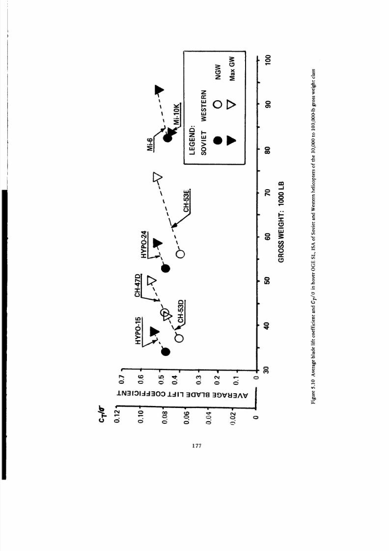
8/3/2019 Stepi Soviet 1
http://slidepdf.com/reader/full/stepi-soviet-1 187/298
e
oo
"' d , v t w d,
d _ _ d o _ o
1N31:31-1-1:IO:D 1-11-I 30V'18 39VU3AV
O
o00
8
O
O
o
'7"O
O
8
qO
m
e,
N
"N
<
.im
e_
<
_4
N
177

8/3/2019 Stepi Soviet 1
http://slidepdf.com/reader/full/stepi-soviet-1 188/298
t
a
r z' _ !> o<1
__o4
c::;
| • I
o o
I IEI::IIN 40 ::11:11"191-11:10101:1NIVlN
¢)o
0
t_
0
0o
Q
o _o _
-,- ._
E
0
e,
178

8/3/2019 Stepi Soviet 1
http://slidepdf.com/reader/full/stepi-soviet-1 189/298
iood
1HOI:IM SSO_IO/1SFII:IH1 I:1010_1"1 IV1
I i I
__ ,:
_o
o
•- ,- o. oc5 c5 o
EI:IMOd EIOIOEI-NlVlAi/Id3MOd EIOIOEI-'IlVl
e.,
.=
<cy)
,J
o
O
e..
e..
O .
I,.,
179
8/3/2019 Stepi Soviet 1
http://slidepdf.com/reader/full/stepi-soviet-1 190/298
Overall Figure of Merit (Fig. 5.13). The FMoo of the CH-47D is based on SlIP = f(Wg r) flight
test results (Fig. 5.8). The FMoa values for all of the other helicopters shown in Fig. 5.13 were
obtained through the indirect estimates outlined in Table 5.2. The hovering ceilings OGE are given
for the CH-53D and CH-53E 2' 13 and the hovering weight OGE at SL, ISA is also known for the
CH_53D 13. This information was not available for the Mi-6 and Mi-10K, while the hovering ceiling
values for the hypothetical helicopters shown in Table 5.1 represent spec-required levels- not the
performance-prediction figures. For this reason, the FMoa values for all of the Soviet helicopters
shown in Fig. 5.13 were obtained through the so-called "first approximation" only. As can be seen
from the examples of the CH-53E and CH-53D, this procedure tends to lead to somewhat optimistic
FMoa values. Consequently, the actual overall figure-of-merit levels of the Soviet helicopters shown
in this figure may be a few percentage points lower than the ones indicated.
Vertical Rates of Climb at SL, ISA (Fig. 5.14). Using VTO weights computed from Eq. (1.2),
as well as maximum flying and normal gross weights, the corresponding vertical rates of climb at
SL, ISA were computed for the compared helicopters. The results are shown in Table 5.2 and are
plotted in Fig. 5.14.
A glance at this figure would indicate that the vertical rates of climb of existing Soviet heli-
copters (Mi-6 in the winged, and Mi-10K in the short landing-gear versions) at their maximum flying
weights are either low, as for the Mi-10K, or have no positive value at all, as in the case of the Mi-6
with wings. Without wings, the gross weight at which the latter would have some capability to
climb vertically would be close to 85,000 lb - still below the maximum (93,700 lb), and even normal
(89,285 lb) gross weights.
The situation is different with respect to Western helicopters which have some vertical climb
capabilities, even at their maximum flying weights and, in the case of the CH-53E, the ability to
hover OGE.
With respect to the Soviet hypothetical helicopters, it appears that their designers would like to
provide vertical climb capabilities similar to those of their Western counterparts.
5.4 Energy Aspects in Hover
Table 5.3. The most important inputs required in the study of energy aspects in hover, and
numerical values of hourly fuel consumption per pound of gross weight and zero-time payload, are
indicated in Table 5.3.
In order to perform this comparison on a common basis, maximum gross weights were used for
the Mi-10K, CH-47D, CH-53D, and CH-53E helicopters, as their (Wgr)rnax is lower than or equal to
180

8/3/2019 Stepi Soviet 1
http://slidepdf.com/reader/full/stepi-soviet-1 191/298
O¢n
I
I
1,0
0
! !
o 0
11EI3_ 40 S.=l_nOl=l "I'IVEI3AO
oo
oo_
o00
¢)
=0
oI.O
m.o
o
o
I.M
..I
O¢)o
"1-
uJ
Ore
¢d
e_
o
o.
8
8
e-
<
r_
o
.g
181

8/3/2019 Stepi Soviet 1
http://slidepdf.com/reader/full/stepi-soviet-1 192/298
o
r
Do<]
/i
t
/
t/
/
tt
/
/
J
j,1
f
/
f
1
t
/
/
t
_4__-tJ
J
°_
21_t- --
-- _=q- - _- ....
e _
I
ooQ
• -g •
•0 0
I.O 0 I._
IAId=I:SIAII-IOIO=I.I.VI:I_:DI.I-I:I=tA
o
g
0
J S
-" g
g
5> g -_
g <
e_
-d
o _
o
o
>
182

8/3/2019 Stepi Soviet 1
http://slidepdf.com/reader/full/stepi-soviet-1 193/298
<
<
o
or_
n"
uJ
oo
o
o
o
• 66 o. 6 6 666o
o _ o _ _ _
_ _ _.- .q . ._ 6_3 _° o_6oooo
•-- . °
6 _ _ _ 6 o ....._ _00000
a_
3:
(.9
LU
u_
u_or_
(D
_J
o 5:. 0 ._ J
_.. __
_ - _ u.__ _ _ 0 _
- _ _... _ s _o __ _:
8 _e_o _ oo ,,,,
._m
0
or -"
ouJ _
t9 t_
0 E
183

8/3/2019 Stepi Soviet 1
http://slidepdf.com/reader/full/stepi-soviet-1 194/298
their hovering weight OGE at SL, ISA. Calculations were performed for the Mi-6 at (Wgr)vr 0 =
81,800 lb since, at higher gross weights, the winged version of the Mi-6 can not hover OGE at SL,
ISA. For the hypothetical helicopters, gross weights corresponding to hovering OGE at SL, ISA
were computed, and arbitrarily assumed to be their maximum flying gross weights. Therefore, these
higher gross weight values were used in the considerations of the energy aspects of the two heli-
copters.
Houri}, Fuel Consumption per Pound of Gross Wei[_ht in Hover OGE_ SL r ISA (Fig. 5.15).
Both Soviet and Western helicopters appearing in Fig. 5.15 exhibit a similar rate of fuel consumption
per pound of gross weight in this regime of flight. The highest is for the Mi-6 (0.0833 lb/hr-lb) and
the lowest for the hypothetical 24-ton helicopter (0.0723 lb/hr-lb), and the CH-47D (0.0734
lb/hr-lh).
Hourly Fuel Consumption per Pound of Payload in Hover OGE, SL, ISA (Fig. 5.16). The
picture changes radically when hourly fuel consumption in hover per pound of payload instead of
gross weight is calculated. It can he seen from Fig. 5.16 that in this respect, existing Soviet heli-
copters (especially the Mi-6 with wings) perform rather poorly when compared with their Western
counterparts.
By contrast, the Soviet hypothetical helicopters exhibit a low hourly fuel consumption per
pound of payload- comparable with that of the CH-47D, representing the best performance in that
respect of all considered Western helicopters of the same class.
5.5 SHP Required Aspects in Level Flight at SL, ISA
Establishment of the (SHP/W_r) = f(V) Relationship. Flight-test substantiated manufacturers'
data on SlIP = f(V) at SL, ISA were available for the CH-47D (Fig. 5.17, courtesy of Boeing-Vertol
Company). Consequently, these inputs were directly used to calculate (SHP/Wgr) = f(V) at the
maximum flying gross weight of 50,000 lb. The "two-point technique" for War = 50,000 and 33,000
lb was employed to determine the equivalent plate area (f) and the average blade profile drag coeffi-
cient (_d). The results of the calculations are shown in Table 5.4.
In this table the Td values obtained for the two considered gross weights are quite similar,
while the values of the equivalent fiat-plate area differ by about 10 percent. This difference can
result from variation in trim drag at the widely different gross weights, and could also reflect an
error in the induced drag coefficient level (assumed in both cases as hindf = 1.8 at Vrnax and 1.7
at Ve). In order to take into account those possible errors, an average value of f = 98.5 sq.ft, was
184

8/3/2019 Stepi Soviet 1
http://slidepdf.com/reader/full/stepi-soviet-1 195/298
;C
i
!
q
91-UHIBq
; ! ! w _ I g 9 !
0 0 0 0
:AAO -IO EllH3d NOI.LclWRSNO0 "1:11"I-.I'IEIriOH
.O
O
O03
O¢0
nf_
===on-
OI.O
O
OOq
¢1
O
C,
o
E
;>O
<
r,/3
©
>O
..=
.o
0
0
w
E
e_
8
O
N
_4
185

8/3/2019 Stepi Soviet 1
http://slidepdf.com/reader/full/stepi-soviet-1 196/298
.J
aa.J
2Jo.
.-I
zOm
o.
Z0
.-Il.IJ
I.L
>...=I
0
0.50
0.40
0.30
0.20
0.10
Mi-6
Mi-10K
CH-53E
I
20 40 60
HOVER TIME: MINUTES
Figure 5.16 Variation with time of hourly fuel consumption per pound of maximum payload in hover OGE, SL, ISA
for Soviet and Western helicopters of the 30,000 to lO0,O00-1b gross weight class.
186
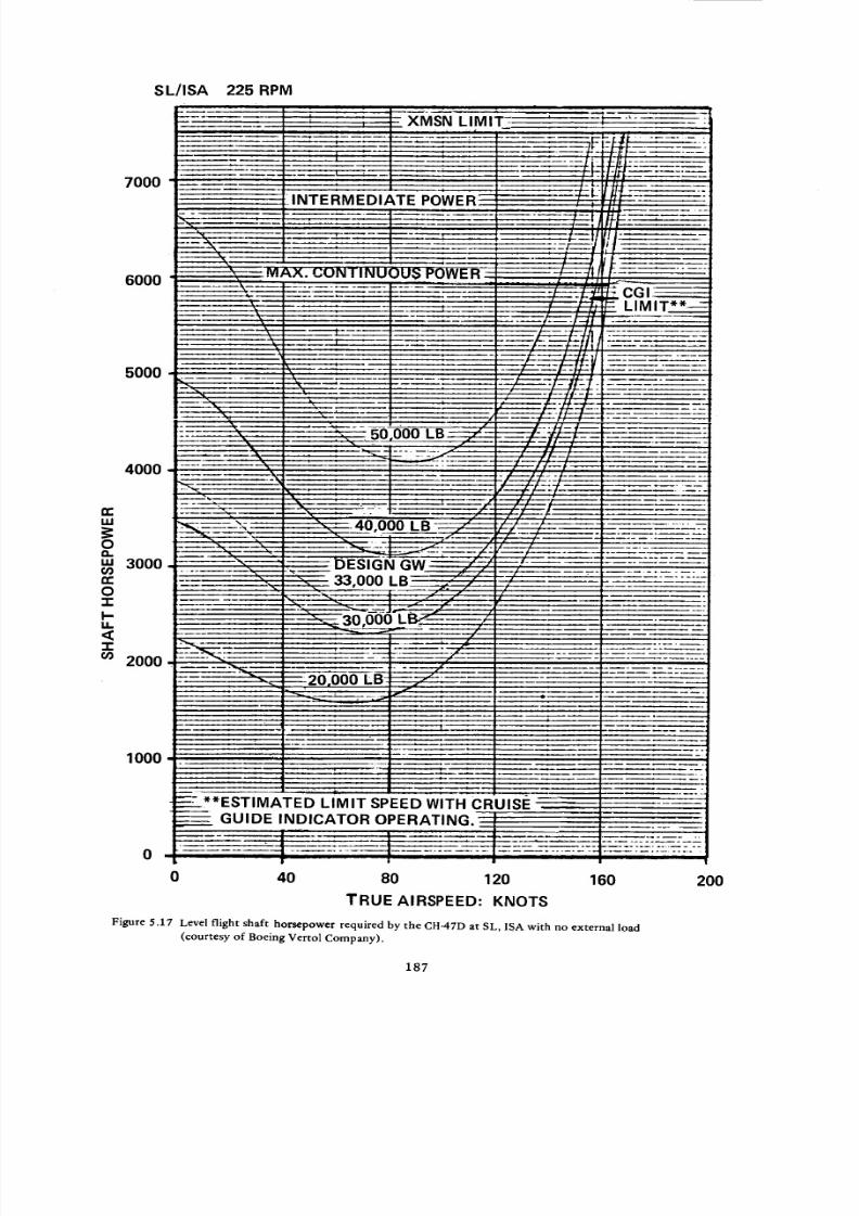
8/3/2019 Stepi Soviet 1
http://slidepdf.com/reader/full/stepi-soviet-1 197/298
S L/ISA
7O0O
I
I
6000
5OOO
uJ
O
uJ
03n-'
O'I-
I'-M.
,¢'I"03
4000
3000
2000
1000
0
000 LB
SIGN
33,000
)00
ATED LIMIT SPEED WITH CRUISE
GUIDE INDICATOR OPERATING.
0 40 80 120
TRUE AIRSPEED: KNOTS
160 200
Figure 5.17 Level flight shaft horsepower required by the CH-47D at SL, ISA with no external load
(courtesy of Boeing Vertol Company).
187

8/3/2019 Stepi Soviet 1
http://slidepdf.com/reader/full/stepi-soviet-1 198/298
ITEM
kindf at Vma x
kindf at Ve
kvf at Vma x
GROSS WEIGHT: LB
50,000 33,000
ASSUMED VALUES
1.8
1.7
1.03
1.8
1.7
1.03
kvf at V e
l"toa
Wfp: psf
f: sq.ft
5d
1.04
0.96
1.04
0.96
COMPUTED VALUES
487.2
103.7
1/58.5
0.55
0.0094
353.2
93.42
1/39.0
0.362
0.0093
Table 5.4. Equivalent fiat plate area and average blade-profile
drag coefficients computed for two gross-weight
values, using data from Fig. 5.17.
assumed as being correct, and is shown in Table 5.5 with the corresponding equivalent flat-plate
area loading level of wfp = 507.1 psf. The (SHP/Wgr) = f(V) curves for gross weights of 50,000 and
33,000 lb, computed directly from the data in Fig. 5.17, are plotted in Fig. 5.18.
Published performance figures for the CH-53E and CH-53D helicopters permitted one to first
apply the single-point technique for the original estimation of Wfp and hence f values, and then to
check them vs the two-point approach where, in addition, the cd_ and c-o values were obtained.
In the case of the CH-53E, where performance figures are known, and SHPmi n is given by the
manufacturer for Wgr = 56,000 lb, both the single and two-point approaches were used at that gross
weight as shown in Table 5.5. It can be seen from this table that through the single-point approach,
f = 124 sq.ft; and through the two-point approach, f = 140 sq.ft. For calculations of (SHP/Wgr) =
f(V) at Wgr = 73,500 lb, the single-point f value was judged as more representative; thus resulting in
wfp = 592.7 psf.
With respect to the "Ed levels, a relative difference between the assumed Ed = 0.0098 in the first
approximation and that resulting from the two-point approach is significant (_d = 0.0098 vs _d =
0.0067. In order to reduce possible errors in calculations of (5HP/War)= f(V) at Wg r = 73,500 lb, an
average of the above two profile drag coefficients was assumed; i.e., _d = 0.083, resulting in -Ed/E _ =
1/56 at _-_ = 0.47. The results of the ($HP/Wg r) = f(V) calculations are plotted in Fig. 5.18.
For the CH-53D, the performance figures given for War = 36,693 lb 2' 13 served as a basis of the
f and _a estimates. In this case, the results of both the single and two-point approaches showed some
188
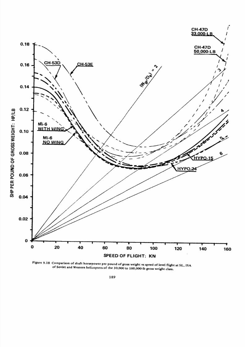
8/3/2019 Stepi Soviet 1
http://slidepdf.com/reader/full/stepi-soviet-1 199/298
-I
a..am
-rL_m
w
OL_ILO
z
OeL
tW
eL
O."r
0.18
0.16
0.14
0.12
0.10
0.08
0.06
0.04
Mi-6NO
CH-47D /"
CH-47D
5q.oOO.LB /
/ ,, .i/
/ ,///×
0.02
0
0 20 40 60 80 100 120
SPEED OF FLIGHT: KN
Figure _.18 Comparison of shaft horsepower per pound of gross weight vs speed of level fl ight at SL, ISA
of Soviet and Western helicopters of the 30,000 to lO0,O00-1b gross weight class.
140 160
189

8/3/2019 Stepi Soviet 1
http://slidepdf.com/reader/full/stepi-soviet-1 200/298
bO
--1
.[j
[" L_< --
,-.l 0
<,SO
o"
_ _ _o_ _;o_ _
._n
£_zz _ z zz z z z z o
-r-i-
u c
sg
'-r
._ o
i--
£r_ z z _--z z z z z z z 6
. • o
tn
_ o .._ c CE _ o o o o o
_ rr n" tr rr _ "
.... q_00_0
• . • .0_ ."_. r.L
E
_.._ ga a a a_.__ _._
,E
o
E
__0 .c
Z _E E
< <
/4
I-
0
Z
190

8/3/2019 Stepi Soviet 1
http://slidepdf.com/reader/full/stepi-soviet-1 201/298
oo _ o
tO _ GO _ t')o 0 o
0 0 0 0 0 0 0 Q
_c_ _- _ ....oooooooo
o
o
A
r •
00000000
A
0
_0
_m
o
o"co
o
. LD
CO 0 0 Z
_c0 0_ 0
._J
== _ "r
_000000
66666666
00000000
00000000
.0
.J•. _/)
_z
ffl
F,-
191
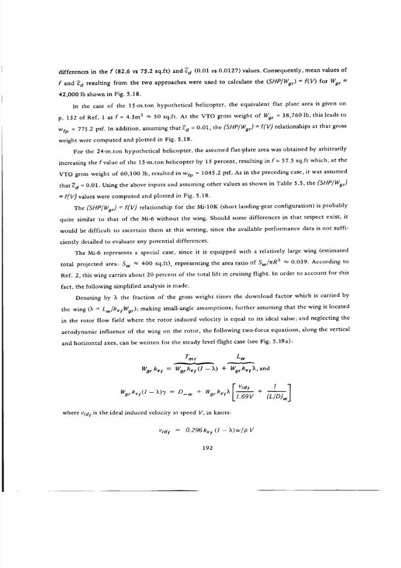
8/3/2019 Stepi Soviet 1
http://slidepdf.com/reader/full/stepi-soviet-1 202/298
differences in the f (82.6 vs 75.2 sq.ft) and _a (0.01 vs 0.0127) values. Consequently, mean values of
f and ca resulting from the two approaches were used to calculate the (SHP/Wg r) = f(V) for War =
42,000 lb shown in Fig. 5.18.
In the case of the 15-m.ton hypothetical helicopter, the equivalent flat plate area is given on
p. 132 of Ref. 1 as f = 4.5m 2 _ 50 sq.ft. At the VTO gross weight of Wg r = 38,760 lb, this leads to
w¢o = 775.2 psf. In addition, assuming that Fd = 0.01, the (SHP/Wor) = f(V) relationships at that gross
weight were computed and plotted in Fig. 5.18.
For the 24-re.ton hypothetical helicopter, the assumed flat-plate area was obtained by arbitrarily
increasing the t'value of the 15-m.ton helicopter by 15 percent, resulting in f = 57.5 sq.ft which, at the
VTO gross weight of 60,100 lb, resulted in wto = 1045.2 psf. As in the preceding case, it was assumed
that_ d = 0.01. Using the above inputs and assuming other values as shown in Table 5.5, the (SHP/Wgr)
= f(V) values were computed and plotted in Fig. 5.18.
The (SHP/Wgr) = 1:(1/) relationship for the Mi-10K (short landing-gear configuration) is probably
quite similar to that of the Mi-6 without the wing. Should some differences in that respect exist, it
would be difficult to ascertain them at this writing, since the available performance data is not suffi-
ciently detailed to evaluate any potential differences.
The Mi-6 represents a special case, since it is equipped with a relatively large wing (estimated
total projected area:S w
_ 400 sq.ft), representing the area ratio ofSw/TrR
2-_
0.039. According to
Ref. 2, this wing carries about 20 percent of the total lift in cruising flight. In order to account for this
fact, the following simplified analysis is made.
Denoting by X the fraction of the gross weight times the download factor which is carried by
the wing (_k -- Lw/hvf Wgr); making small-angle assumptions; further assuming that the wing is located
in the rotor flow field where the rotor induced velocity is equal to its ideal value; and neglecting the
aerodynamic influence of the wing on the rotor, the following two-force equations, along the vertical
and horizontal axes, can be written for the steady level-flight case (see Fig. 5.19a):
Tm r L w
Wgrkvf :_)+ Wgrkvf;k, and
_dfwg_kvf(l-X).y- D _, + Wgr#v_Xr + _
- [1.69 V (L/D)w
where rid t is the ideal induced velocity at speed V, in knots:
Vid f = 0.296#_f (I - X)w/p V
192

8/3/2019 Stepi Soviet 1
http://slidepdf.com/reader/full/stepi-soviet-1 203/298
(w being, as before, the nominal main-rotor disc loading at the considered gross weight) and (LID)w
is the lift-to-drag ratio of the wing carrying the L w = kvf_k Wg r load.
Examining the above two equations, one should note that the total SHP required by the heli-
copter in horizontal flight can be expressed as a sum of power required by a wingless helicopter
!
flying at Wg r = (I -- X)Wg r and additional shaft horsepower due to the wing, which can be expressed
as:
SHPw = %rkv Xlkv 0.296(7- X)w/V2p+ [7/(L/O),,]}1.69V/SSOno, (51)
or, rewriting the equation in terms of additional power per pound of gross weight, it becomes
(ASHPw/Wg r) = 1.69kvfXV{O.296kvf(l-?_)w/pV 2 + [I/(LID)w ] }/550rlo * (5.1a)
and the equation for the total power required per pound of gross weight in a steady-state level flight
now becomes:
(SHP/%r) =V 3 k2vfkindf(] - _k)W
12.413p o _ + 0.296
Wfp p V
4 7" _'/Ca\
+ o.zs(l+ . 'tT) v, +
1.69hvf_, V .296kvf(l - X) --p 2 + (LTD)w 50rio a(5.2)
Similar to Eq (1.10), Eq (5.2) can be used in the single as well as in the two-point approach. In
both cases, knowledge of the (L/D)w values is required. For the Mi-6 wing L/D = f(_) characteristics
were obtained taking this relationship as the basis for a wing ofAR = 4.5 as given in Fig. 2.1011 , and
recalculating it for AR = 6.3 of the Mi-6 helicopter wing (Fig. 5.19b).
Since no data regarding the forward rate of climb of the Mi-6 helicopter is available at this writing,
the single-point approach was used, assuming a gross weight of 93,700 Ib and Vma x = 162 kn. Twenty
percent of the load is carried by the wing. Based on the total projected wing area, this results in a
nominal wing loading of ww = 47.79 psf and the corresponding _ = 0.54 at SL, ISA. From Fig. 5.19b,
one finds that (L/D)w = 18.8.
The main-rotor disc loading in this case would be w' = 0.8 X w = 7.24, and the blade average
lift coefficient would be _-p = 0.40. Assuming that" a = 0.0096 and hence, _/_ = 1/42, Eq (5.2) was
solved for w¢p, resulting in (Wfp)_ w = 902.5 psf and f-w = 103.8 sq.ft.
As shown in Table 5.5, the total equivalent plate area loading (wfp)tot and the total equivalent
flat plate area ftot values were calculated through a single-point technique, assuming that the wing
carries no load.
193

8/3/2019 Stepi Soviet 1
http://slidepdf.com/reader/full/stepi-soviet-1 204/298
(a) NOTE: D-forces not to scale
of lift end weight forces
(b)
2O
-- 10
zE
0 0 4 0.8 1.2 CL
J I _' g
0 4 8 12 16 (0_0W)6_3
Figure 5.19 Scheme of velocities and forces of winged helicopter, and (b) wing lift-to-drag ratio
vs wing-lift coefficient for _ = 4.5 (Ref. 1) and _ = 6.3.
194-
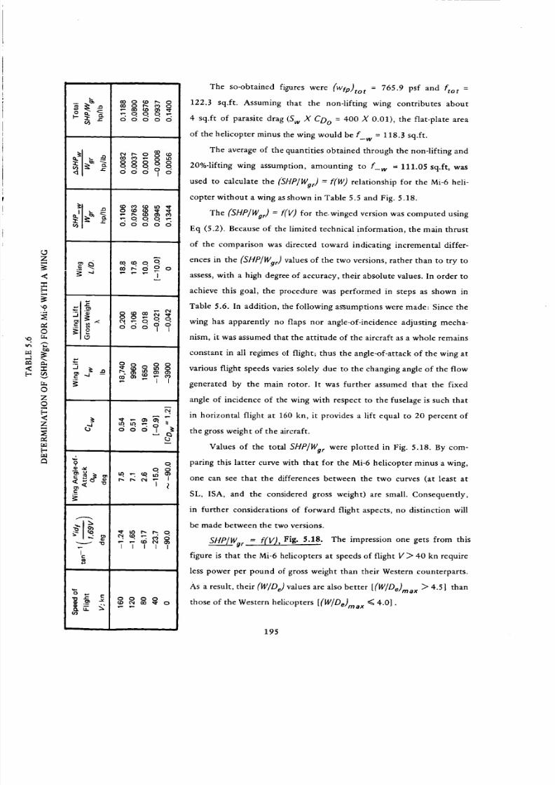
8/3/2019 Stepi Soviet 1
http://slidepdf.com/reader/full/stepi-soviet-1 205/298
<
Z
<
'9,
©
.v
O
Z©
<Z
£(3
_d
_L9
e_ _ "o
¢-
v "o
00000
oo_oo
mqqq_00000
ooo1_
qO0
IIIII
The so-obtained figures were (wfp)tot = 765.9 psf and ftot =
122.3 sq.ft. Assuming that the non-lifting wing contributes about
4 sq.ft of parasite drag (Sw X CDo = 400 X 0.01), the flat-plate area
of the helicopter minus the wing would be f--w = 118.3 sq.ft.
The average of the quantities obtained through the non-lifting and
20%-lifting wing assumption, amounting to f-w = 111.05 sq.ft, was
used to calculate the (SHP/Wgr) = f(W) relationship for the Mi-6 heli-
copter without a wing as shown in Table 5.5 and Fig. 5.18.
The (SHP/Wgr) = f(V) for the.winged version was computed using
Eq (5.2). Because of the limited technical information, the main thrust
of the comparison was directed toward indicating incremental differ-
ences in the (SHP/Wgr) values of the two versions, rather than to try to
assess, with a high degree of accuracy, their absolute values. In order to
achieve this goal, the procedure was performed in steps as shown in
Table 5.6. In addition, the following assumptions were made: Since the
wing has apparently no flaps nor angle-of-incidence adjusting mecha-
nism, it was assumed that the attitude of the aircraft as a whole remains
constant in all regimes of flight; thus the angle-of-attack of the wing at
various flight speeds varies solely due to the changing angle of the flow
generated by the main rotor. It was further assumed that the fixed
angle of incidence of the wing with respect to the fuselage is such that
in horizontal flight at 160 kn, it provides a lift equal to 20 percent of
the gross weight of the aircraft.
Values of the total SHP/Wg r were plotted in Fig. 5.18. By com-
paring this latter curve with that for the Mi-6 helicopter minus a wing,
one can see that the differences between the two curves (at least at
SL, ISA, and the considered gross weight) are small. Consequently,
in further considerations of forward flight aspects, no distinction will
be made between the two versions.
SHP/Wg r = f(V,), Fig. 5.18. The impression one gets from this
figure is that the Mi-6 helicopters at speeds of flight V > 40 kn require
less power per pound of gross weight than their Western counterparts.
As a result, their (W/De) values are also better [(W/De)max > 4.5] than
those of the Western helicopters [(WIDe)rod x <_ 4.0].
195

8/3/2019 Stepi Soviet 1
http://slidepdf.com/reader/full/stepi-soviet-1 206/298
It should be emphasized, however, that the Mi-6 (SHP/Wgr) = [(V) curves are predicated on the
validity of information 2 regarding gross weight (93,700 lb), and total engine power (11,000 hp) corre-
sponding to the quoted Vmn x = 162 kn. But even accepting some possible errors in that data, it can still be
concluded that the Mi-6 helicopter represents a case of well-selected design parameters leading to forward
flight aerodynamic characteristics which, probably, are at least on the level of those of the corresponding
Western helicopters.
It can also be seen from Fig. 5.18 that the so-called hypothetical helicopters represent a goal, or at
least a desire, to achieve low (SHP/Wor) values at both moderate (40 < V < 100 kn) and high (V> 100)
speeds of flight.
With respect to the (SHP/Wgr) = f(V) curves of Western helicopters, it should be pointed out that
only in the case of the CH-47D are those relationships based on flight-test-supported SHP= f(V) data,
while for the CH-53D and CH-53E, previously discussed indirect methods were applied, using published
performance figures aAz and manufacturer's data.
(SHP/Wgr) Values at Vma x. Figure 5.20 supports the previous statement that if one accepts the
performance data and engine ratings as given in Ref. 2, then the aerodynamic cleanness of the Mi-6 heli-
copter should be better than that of its Western counterparts. With respect to the future design trend of
Soviet helicopters as reflected in the hypothetical rotorcraft, it is clear that the Soviet designers will try
to maintain, or improve, the degree of aerodynamic cleanness of their large transport helicopters.
5.6 Energy Aspects in Level Flight, SL, ISA
Fuel Required per Pound of Gross Weight. The numerical inputs required for determination of the
fuel required per pound of gross weight are given in Table 5.7, while the results of the calculations are
shown in Figs. 5.21 and 5.22.
It is evident from these figures that the Mi-6 helicopter appears to have an hourly fuel consumption
per pound of gross weight similar to those of Western helicopters of the same gross weight class. The same
is true regarding the fuel required per pound of gross weight and 100 nautical miles.
By contrast, in the hypothetical helicopters, one can detect the desire and hope of Soviet designers
to develop machines with a better basic fuel economy than that of their own existing as well as Western
helicopters.
Fuel Requirements per Pound of Zero-Range Payload (Table 5.8 and Figs. 5.23 and 5.24. Because
of the relatively higher structural weight (as expressed by the We/Wgrmax ratios) of the Mi-6 and Mi-10K
helicopters, their fuel requirements per pound of payload (and either one hour or 100 n.mi) are much
higher than those of Western helicopters. However, here again with respect to the hypothetical helicopters,
one can detect a desire to create rotorcraft with superior fuel economy characteristics related to payload.
196

8/3/2019 Stepi Soviet 1
http://slidepdf.com/reader/full/stepi-soviet-1 207/298
©
+0+I \
iiiiii
=m+
\
+.+I>oEJ
'_ _ mo
,,+, i_ o +=.;.<
\\
\
\
\
O
O
8"lldH
I I I
I._ O I.O,e- se.- O
:1HgI3M 8801:10 .-10 ONf'IOd t:13cl dH8
•,, 00
O
2
iiiiii
" O..t,,/')
X<
0
0
CN
coo
o
"7"0
0
o0
0
o0
C:,
o0
O.
.o
£:
c0
0c./J
c_
.JC/)
w-
>
X
>
o
"0e-.
Q.
0Q.
0J=
0
c!.L._
It
197
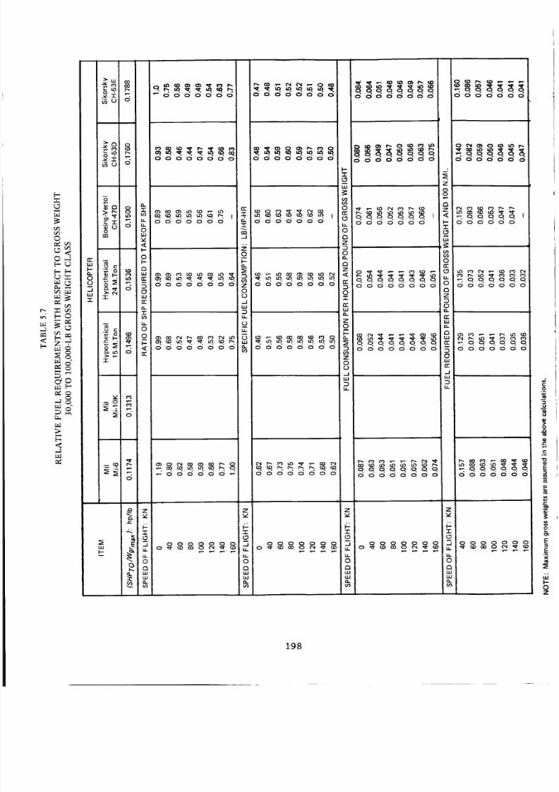
8/3/2019 Stepi Soviet 1
http://slidepdf.com/reader/full/stepi-soviet-1 208/298
o.+ _0000000
o__.00000000
QQQqqqqQOOOOOOOO
_oqq_qqOOOOOOO
r'-
<E-
[-
00
©
O_
m_
r_
r_
>
<
rr
"r
+1,-:_0_ o
_o o "
•_ o o
o 0
v
<
o
•_ o
-r
•_ o _ 0
Q. LO 0 tT>. p
-r
_Z ¢0
=o
0
00000000
0000000
_OOOOOO_
OOOOOOOO
0-
"1"
-J
Z
O
I-0_
o(2
--I
LU
DLL
C.)
U-
,%
OOOOOOO
dddddddd
'OOOOOOOO
I--
"I"
(.9
LU
ooOOOOOO
09U')
o
LL
o
oZ
.qqqqqqlOOOOOOO
OOOOOOO
Z
0o.
o
0"1"
O__
OOOOOOOO
O
O
o
•-: o. o. o. o. o. II-- O O O O O O
"1-
Z
0
,r.O
,Z
O
(.2
._1
00000000
U_
0909
on-
O
Z
0
o.
QQQQQQQQOOOOOOOO
n"I,LI
a.
8n-
50LU
n"
_1
LU
D
U-
-ooooo 1
_OOOOOO
_QQQQQo0000000
..
Z
v
#"1"
oLU
LU
CO
o_8888_8
zx/
"I-
_D
u.
0
nI.U
o_8_
Z
v
-r
(_9
LL
o
oLLI
LU
,%
o_888_8
z
I
0
_888_88
o
198

8/3/2019 Stepi Soviet 1
http://slidepdf.com/reader/full/stepi-soviet-1 209/298
I
I
o,q,
0N
o 0
ME) dO 8"! _ IdH I:l::ldNOIJ.dlAII3SNO0 "l:lNd
o
199
0
0
O,,,-i
8
E
<
.__
T
.__
e,
0

8/3/2019 Stepi Soviet 1
http://slidepdf.com/reader/full/stepi-soviet-1 210/298
• •
o
o
oN
oo
z
o
-1-
m
,-Iin
I.,I,.
ann0nnnQ..
0
0
N
0
"!IN'N 00L-8"i/8"1 :!IN'N OOL • ME) -10 CINNOd 1:13d"131"1-1
O
Q
0
e_
e_
e-
.<
.,..:
0
200

8/3/2019 Stepi Soviet 1
http://slidepdf.com/reader/full/stepi-soviet-1 211/298
<0
<_w
Z<
6
N
O
Z
.1
<
O
-r
O
"r
Ro
8_
O
"1-
'_ 0 _ _
7-
_ co o
_ o
a<o.J
>-<O_
W
z<
O
N
u_
O
O7-
n"
a.
O
O
..J
W
u_
Z
7-
..1
u.
o
o
W
o.
00000000
_.._.._
00000000
•'7 ,7 ,70 ,7 .,-:. ,7 I0 0 00 00 0
' m:
,7. o.o.o.o.o.o.o.0 0 0 0 0 0 0 0
I
I
o30 CO r_ I',.. (_00'_ 0'}
_ 0 0 0 0 0 0
,5 ,5 c_ (5 d c_ ,5 c_
I I
!
0000000
I
_0__
00000000
0000000
0_0_
.2'
z
00
oz
<
o<0.-I
>.<o.
W
L9
Z
<
g
N
z
o
ffl
O
zv
.r
_.1
O121W
w
o_
_qqqq0000000
_000
_0_
'_5_,__. _. o. o. o. o. o.0 0 0 0 0 0 0
I
i
u"} _ 0'} r'... r'.- co (D
_. _. o. o. o. o. o.0 0 0 0 0 0 0
I I
I__0_
_ .... I000000
I
_0__
0000000_0_
0
_0
0
"5
D
_o
c
0
0
I'-
Oz
201

8/3/2019 Stepi Soviet 1
http://slidepdf.com/reader/full/stepi-soviet-1 212/298
/ /if) ¢_ I._ 0 It)
o o c:; c:; o
8-1-_1H/8-1
0
:7d ::IONVEIOEI=IZdO ONnOd _ UnOH 1=13d=ll=llnO=lu '13nd
0
0
0
zv'
,-IU.
ii
ILl1.1.,I0,..f./)
0
0¢N
.o
,.o'7"
o
1-(
0
r,
=.
0
<
0_
0
=.
"0
0
=.
0r,
f,nt4
i,n
202

8/3/2019 Stepi Soviet 1
http://slidepdf.com/reader/full/stepi-soviet-1 213/298
• i I. w
om.o
• • & • | i • • w w I l • • • ! . • • • 0
0 0 0 0 0
"!IN'N 001,-8"1/8"1 :!IN'N OOL• ld ggNVI:I OI:IgZ :10 ONrlOd U3d 131"1::1
o_D
0
0
00
I--"r
o- £1.IJ=
0r_IJJ
o
o
0
e_
0
0
q00
00
q0e_
°.
..C
0
<r_
J
c-
O0
0
C
0
e_
203

8/3/2019 Stepi Soviet 1
http://slidepdf.com/reader/full/stepi-soviet-1 214/298
Fuel Required per Pound of Payload vs Distance (Table 5.9). The above-established trend in fuel
economy with respect to unit of weight of the zero-range payload is further confirmed in the computations
shown in Table 5.9, and the fuel required to carry one pound of payload over various flight distances is
graphically presented in Fig. 5.25. Here, again, the Mi-6 and Mi-10K helicopters exhibit the highest, and the
hypothetical helicopter, the lowest fuel requirements.
5.7 Productivity
Productivity Index. The inputs necessary to calculate the productivity index from Eq (1.17a) are
indicated in Table 5.10. Similar to Section 4.6, the PI evaluation was also limited to the specified Verma x
only. The results are graphically presented in Fig. 5.26. The Mi-6 and Mi-10K helicopters also exhibit the
lowest relative productivity of the whole considered gross weight class, while the highest PI values are pre-
dicted for the 24 re.ton hypothetical helicopter. The relative productivity of the 15 m.ton helicopter would
be on the same level as that of the CH-47D and CH-53E.
5.8 General Discussion and Concluding Remarks
Because of its size and large quantity of aircraft in both military and civilian use, the Mi-6 helicopter
is the most important representative of existing Soviet helicopters in the 30,000 to 100,O00-1b gross weight
class. Unfortunately, at this writing, the lack of reliable performance figures defining gross weight, engine
rating, and flight altitude corresponding to the quoted maximum flying speed 2, as well as a complete lack
of information on the maximum rate of climb in forward flight, makes it difficult to carry the forward
flight analysis to the precise level one would like to achieve for this important machine. Consequently,
an element of uncertainty is present, not only in the (SHP/Wg r) = f(V) relationship, but in the following
relationships for both the Mi-6 and its sister design, the Mi-IOK helicopter.
Based on the limited data, even if the calculated wfp _ 800 psf for the Mi-6 at its maximum gross
proved to be optimistic when compared with w¢o ._ 500 to 600 psf for its Western counterparts, both it
and the Mi-IOK (the shortqanding gear version) should be considered as aerodynamically clean rotorcraft.
Other aerodynamically important parameters such as disc loading, tip-speed, and rotor solidity ratio,
appear to be well selected, resulting in the operational levels of the average blade-lift coefficients (CT/O),
rotor advance ratios, and blade tip Mach numbers being, in various regimes of flight, similar to those of
the Western designs.
However, there are areas where the design philosophy of the Mi-6 and Mi-IOK departs from that of
the West. For instance, the power loading of both helicopters, but especially that of the Mi-6 at its maxi-
mum gross weight (Wg r = 93,700 lb, and an officially-stated engine rating of SHPTo = 5500 hp) is
markedly higher than that of the American CH- types. This results in inferior hovering and vertical climb
characteristics of the Mi-6; especially of its winged version. Although Wgr = 93,700 lb is quoted in Ref. 2
as the maximum gross weight, still allowing vertical takeoff at SL, ISA, this statement probably refers to
204
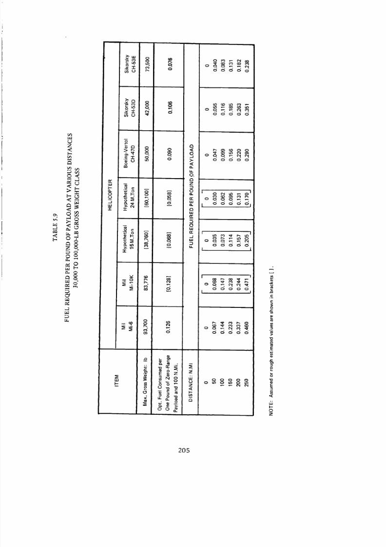
8/3/2019 Stepi Soviet 1
http://slidepdf.com/reader/full/stepi-soviet-1 215/298
Ox
,-1
<[-,
Z<D
O<
<
0
Zq
£s
M
8
"1"
_ o co0 r_
_m, m q
_o r-
o
o , . .
a
_,0 o o <
. q
o @
O,Q
z
'_ D
:_ _. o n"
-r r_
uJ
r_
D
0"_ ,,,
u ,.- rr r
_. _ ©
"1-
=_
_4 6
¢. , .
o o _ 7
O3
® o
00_
00000
00000
00000
0_0_0
oqqqm_00000
__0
6o6oo
[ 1
00000
00000
00000
0_0_0_
.(3
.E
0
o)
0o
E
g
o
E
6J
0
Z
20S

8/3/2019 Stepi Soviet 1
http://slidepdf.com/reader/full/stepi-soviet-1 216/298
8"1/8"1 :I,4 40 81 l:13d O31:llNO3kl "1:1114
0
,.o'7"
0
Q
£
0
_S
r,
o
"S<
J
0
"S
0
u_
&
206

8/3/2019 Stepi Soviet 1
http://slidepdf.com/reader/full/stepi-soviet-1 217/298
,--1
_D
.<[-,
_z _ d d o
. _ _ o.
o_ 1.0
en
• ". _r _ o.
-i- I
Z _1- ,... _ ,.0 m' - _r i,,0 _ 0
-- o" "">o
0 0 .-: o_" • ¢"0 CO 0
_66 _ o
=_ o5° _eO 0
ill
I--
n"
z
._l
oo
ii
II1
_.1
>
X
U.l
Z
I--
0
0 _0 I.O
o _. _
_. cq.
0 00 0 0
0
E
I::
0
Z
207
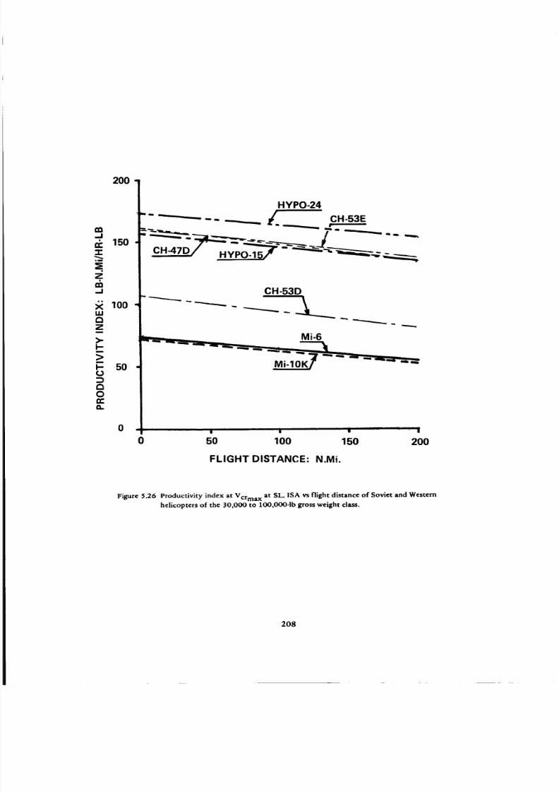
8/3/2019 Stepi Soviet 1
http://slidepdf.com/reader/full/stepi-soviet-1 218/298
200 1 HYPO-24
/ - _---'-_ ...=- =_ J
°_
z,IXl..I
u.I
z
I-ra>m
l--(J:3a0n.,o.
100
-5O
CH-53D
0 50 100 150 200
FLIGHT DISTANCE: N.Mi.
Figure 5.26 Productivity index at Vcrma x at SL, ISA vs flight distance of Soviet and Western
helicopters of the 30,000 to 100,000-1b gross weight class.
208

8/3/2019 Stepi Soviet 1
http://slidepdf.com/reader/full/stepi-soviet-1 219/298
hovering and limited vertical climb in ground effect only. Remarks in Ref. 1 seem to support this
suggestion, as on p. 118 it is stated that the Mi-6 in normal operations either takes off in ground
effect or with a ground run, while Fig. 2.621 shows the total power for HOGE at SL, ISA as 13,000
hp =.
The purpose of using a wing having a fixed angle of incidence, and with no flaps appears unclear.
In hovering and vertical climb, the wing produces a download amounting to about 4 percent of the
gross weight and, in flight at low altitudes and standard temperatures, provides no apparent benefit.
However, performance benefits may be present in flights close to service-ceiling altitudes. Also, at
elevated or even intermediate altitudes, the wing may contribute to an achievement of maneuver load
factors higher than for the wingless configuration.
In general, it may be stated that when performance effectiveness criteria is referred to units of
gross weight, both of the Mil helicopters exhibit design effectiveness levels similar to those of the
American helicopters of the same gross weight class.
By contrast, because of the higher structural weights and inferior specific fuel consumption
characteristics of the Mi-6 and Mi-10K helicopters, all of the performance effectiveness criteria re-
ferred to units of payload rather than gross weight indicate large unfavorable differences from those
of the American CH-wpes.
With respect to the hypothetical helicopters, it is interesting to note that they reflect the desire
and, probably, the hope of the Soviet designers to surpass the American designs; not only in the areas
of overall performance reflected in various indices referred to units of gross weight, but also in those
referred to the weight units of the payload.
=This value checks very well with SHPreq = 13,118 hp resultingfrom (SHP/t4/gr)v=0 = 0.14 asshown
in Fig. 5.18 for the winged version, and with Wgr = 93,700 lb.
209

8/3/2019 Stepi Soviet 1
http://slidepdf.com/reader/full/stepi-soviet-1 220/298
Over
Chapter 6
100,000-1b GW Class Helicopters
6.1 Compared Helicopters
Composition of the Group. In the class of helicopters with gross weights exceeding 100,000 pounds,
the Mi-12 (Mil V-12; Fig. 6.1a) represents the helicopter type that has been in limited operational service.
The Boeing Vertol heavy-lift (HI, H) helicopter (XCH-62A, Fig. 6.1b) was developed through the proto-
type stage, but this development ceased several years ago. The two other helicopters included in this group
were purely hypothetical: one of the single-rotor (Fig. 6.1c) and another of the side-by-side (Fig. 6.1d)
configuration. Both are of the 52 re.ton design (normal) gross weight and, similar to the Hypo-15 and
Hypo-24 of the preceding chapter, were reconstructed from inputs provided in Ref. 1. Also, as in the
case of the previous hypothetical machines, they may be considered as forerunners of the conceptual
designs of new heavy-lift Soviet helicopters.
This assumption appears to be correct since, after completion of the review copies of this report,
the Mi-26 helicopter was officially unveiled at the Paris Air Show on June 4 - 14, 1981. The available
characteristics of the aircraft suggest strong similarities to the Hypothetical 52 single-rotor machine. It
therefore appeared desirable to include the Mi-26 in the comparisons performed in this chapter, even
on the limited basis of the available technical characteristics.
It should be noted at this point that in spite of the fact that in Ref. 1, tandems were considered for
heavy-lift operations, there is no hypothetical Soviet tandem among the compared helicopters. This is
because their studies of the 44 to 60-re.ton gross weight class helicopters I showed a definite preference
for the single-rotor configuration with the side-by-side as a close competitor.
Hypothetical Helicopters. Hypothetical helicopters of the 44 to 60-re.ton gross weight range were
considered in Section 2.5.4 of Ref. 1. However, most of the information on design details and weight
aspects applied to the 52-m.ton design gross weight machines. Consequently, this particular gross weight
was selected for the present study. The baseline data which appear as the most important for comparative
evaluation were selected from Table 2.111, and presented (in English units) in Table 6.1. It should be
remembered, however, that in the optimization process of Ref. 1, the rotor-radius and number of blades
become the most important parameters. Hence, in the optimal versions, the rotor radii are different from
the baseline values of Table 6.1.
With respect to the configuration, it is stated in Ref. 1 that the single-rotor helicopters are configured
similarly to the Mi-6, while the side-by-side types have non-intermeshing rotors supported by the truss-type
210

8/3/2019 Stepi Soviet 1
http://slidepdf.com/reader/full/stepi-soviet-1 221/298
I
(a) Mil V-12 four-turboshaft heavy-duty freight-carrying helicopter (Pilot Press).
(b) Boeing Vertol XCH-62A heavy-lift helicopter
Figure 6.1 Drawings of Soviet and Western helicopters of the over 100,000-1b gross weight class.
211

8/3/2019 Stepi Soviet 1
http://slidepdf.com/reader/full/stepi-soviet-1 222/298
ROTOR AXIS 5°
i
(c) Side-view drawing of the hypothet ical $2-m.ton single-rotor helicopter (similar to the Mi-6)
(d) Two-view drawing of the Mil Mi-26 heavy-lift helicopter
212

8/3/2019 Stepi Soviet 1
http://slidepdf.com/reader/full/stepi-soviet-1 223/298
"__" "_, _Helicop fer c.g.
(e) Three-view drawing of the hypothetical $2-m.ton side-by-side heli copter (simi lar to the Mil V-12)
Figure 6.1 Drawings of Soviet and Western helicopters of the over lO0,O00-1b gross weight class (Concluded)
213

8/3/2019 Stepi Soviet 1
http://slidepdf.com/reader/full/stepi-soviet-1 224/298
TABLE 6.1
BASIC DATA ASSUMED FOR THE HYPOTHETICAL 52-M.TON HELICOPTERS
BASIC PARAMETER USED IN CALCULATIONS
Main-Rotor Radius of Baseline Variant: ft
Tip Speed of Main and Tail Rotor: fps at
HhVc,
Average Blade Lift Coefficient; _'Jo
Airframe Download Coefficient for Baseline
Version of Conf iguration: #Vh
FM of Isolated Rotor at H = H h and
Solidity o o = 0.217
Coefficient of Power Utilization in Hover; l"lOah
Coefficient of Power Utilization at Vcr; l"loacr
Distance between Rotor Shafts in the Original
Layout; L: ft
Wetted Area of Fuselage in the Original
Layout; S_: ft 2
Parasite Drag Eq. Flat-Plate Area: ft 2
*No overlap.
HELICOPTER
SINGLE ROTOR
52.5
721.8
689.0
0.465
1.030
0.707
0.83
0.89
66.4
3443
80.7
SIDE-BY-SIDE*
36.1
721.8
689.0
0.513
1.065
0.689
0.95
0.95
72.2
2542
133.4
outriggers, as in the case of the Mi-12. The cargo cabin volume was assessed as 41 X 10 X 10 ft-similar
to the dimensions of the Mi-6 (Scheme B of Fig. 2.641 ).
Hypothetical 52-m.ton Single-Rotor Helicopter (Hypothetical 52-SR). It is shown in Figs. 2.86 and
2.871 that the optimal number of blades of the main rotor of the single-rotor configuration (Hypo-52-SR),
as well as the side-by-side hypothetical 52-re.ton single-rotor helicopters, is nbl = 8. Fixing the number of
main-rotor blades at 8, it appears from Figs. 2.76 through 2.791 that the rotor diameter of D = 33m;
i.e., R = 54.14 ft, represents a good compromise for flight distances from £ = 50 to 800 km. For this
diameter, the referred total engine power (in SI units) is SHPro f = 22,500 hp (Fig. 2.791). This corre-
sponds to the SL, ISA SHPTo ° = 23,250 hp (in English units), which is assumed to be delivered by three
7750-hp engines.
The weight empty (in kg) is derived as follows:
we = %, -(wp/ + w:. + wo,. +
214

8/3/2019 Stepi Soviet 1
http://slidepdf.com/reader/full/stepi-soviet-1 225/298
Taking the flight distance as 800 km, the payload becomes Wp/= 12,800 kg (Fig. 2.781 ); the weight
of fuel as Wtu = 9200 kg (Fig. 2.791 ); assuming a crew of three at 90 kg each, H/crow = 270 kg; and the
weight of trapped fluids as H/t.fluid$ = 20 kg, the weight empty becomes We = 29,710 kg, or 65,510 lb.
Similar to the previously discussed cases of the Hypo-15 and Hypo-24, here also, the nominal
52 m.ton gross weight is assumed to be normal [(Wgr)norm = 114,660 lb]. However, in order to be able
to conduct a meaningful comparison of the performance of the hypothetical helicopters with that of the
Mi-12 and XCH-62A at their maximum flying gross weights, the same weights should also be determined
or assumed for the hypothetical machines.
It is not known at this writing if the quoted maximum flying gross weight of the Mi-12 (Wgrmax =
231,500 ib) 2 was established on the basis of performance or on structural considerations, but both factors
probably had an effect on this determination.
In the case of the XCH-62A, the selection of W.qrma× = 148,000 lb was solely based on structural
criteria: maneuver load factor = 2.0, instead of 2.5 at the design (normal) gross weight. This established
Wgrmax is approximately 10 percent higher than the Wg r = 134,300 lb, permitting hovering OGE at
SL, ISA, with the transmission limited to 17,700 hp.
Since there is no information regarding maneuvering load factors of the hypothetical helicopters,
it is suggested that their maximum flying gross weight would correspond to the hovering ability OGE at
SL, ISA.
Using the same approach as in the case when establishing the VTO gross weight in Section 1.4,
the following formula (analogous to Eq. (1.2)) for the maximum OGE hovering weight at SL, ISA,
(H/grJmaxh , is obtained for single-rotor helicopters:
(Wer)raaxh = 16.54 [(SHPTo)a vR mr FMoa ] 2/3 (6.1)
Where (SHPTo)a v is the total nominal takeoff power of all engines or, in the case of transmission restric-
tion, the transmission-limited total power.
For twin-rotor configurations, Eq (6.1) becomes
(Wer,)maxh = 20.84 [(SHPTo,)av Rmr FMoa ] z/a (6.2)
Assuming that there is no transmission limit, as seems to be implied by Table 2.101 , and FMoa =
0.543 (see Section 6.3), the maximum flying weight of the Hypo-52-SR, based on the hovering ability
as computed from Eq (6.1) would be (Wgr),,,OXh -- (WUr),,a x = 131,375 lb.
This gross weight brings the disc loading to w = 14.26 psf, or 69.6 kg/m z, which is slightly less
than the constraining value 1 of Wma x = 70.0 kg/m 2.
The helicopter characteristics established above were entered into Table 6.2.
215

8/3/2019 Stepi Soviet 1
http://slidepdf.com/reader/full/stepi-soviet-1 226/298
TABLE 6.2A
PRINCIPAL CHARACTERISTICS AND PERFORMANCE
OVER 100,000-LB GROSS WEIGHT HELICOPTERS
ITEM
m
CONFIGURATION
POWERPLANT
Number of Engines
Output Shaft rpm
Total T.O or Mil. SHP
Total Max. Continuous SHP
Transmission Limit, HP
MAIN ROTOR R,ft
Direct ion of Rotat ion
rpm
Number of Blades
Blade 0.7R Chord, ft
Airfoil
Articulation
TAIL ROTOR R, ft
Type
x, ft
y, ft (see Fig. 1.14)
rpm
Number of Blades
Blade 0.7R Chord, ft
Airfoil
Articulation
I, ,,
EXTERNAL DIMENSIONS
Overall Length, ft
Fuselage, f t
Overall Height, ft
INTERNAL DIMENSIONS
Cabin Length, ft
Max. Width, ft
Max. Height, ft
Volume, cu.ft
CREW
HELICOPTER
Mil Hypothetical Mil Hypothetical Boeing Vertol
Mi-12 Hypo 52-SR Mi-26 Hypo 52-SBS XCH-62A
SBS SR SR SBS Tandem
Soloviev
D-25V F
4
26,000
[22,200]
57.42
CW Right
[120]
2X5
3.28
HH, VH, PH
219.83 (span}
121.375
41.00
92.33
14.42
14.42
[ 19,000]
Hypothetical
7750 hp
3
21,500J
54.14
[cw]
127.3
8
2.75
HH, VH, PH
"11.26-
.66.22.
[127.14]
41.0
10.0
10.0
i.4100_
[3]
Lotarev
D-136
2
8300
22,480
52.50
CW
8
[2.73]
12.48
Pusher
5
[1.56]
130.8
26.43*
-40.0"
10.8
10.0
1.4320
Hypothetical
5000 hp
4
m
[ oooo]18,5ooj
39.37
[CW Right]
175.1
2X8
1.72
HH, VH, PH
[158.0 (span}]
-41.0"
10.0
10.0
14100_
[3]
Allison
T701 -AD-700
3
11,500
24,240
21,915
17,700
46.00
CW Front
156.0
2X4
3.33
VR-7 & VR-8
Elastomeric
162.25
89.25
38.625
"60.0"
8.80
6.25
3000
Note:
*Including hub Cont'd
216

8/3/2019 Stepi Soviet 1
http://slidepdf.com/reader/full/stepi-soviet-1 227/298
Table 6.2A (Cont'd)
WEIGHTS
Max. Gross Weight, Ib
Normal Gross Weight, Ib
Weight Empty, IbPayload at Zero Range, Ib 1"
PERFORMANCE
Flight Speed, Max/VNE, kn
Fast Cruise*, kn
Economic Cruise*, kn
Vertical R/C*, fpm
Forward R/C*, fpm
Hover**, OGE, ft
Service Ceiling, ft
Ceiling, 1-Engine Out, ft
Avg. Fuel Consumption, Ib/hr
Normal Fuel, Ib
Range, n.mi
DISC LOADING
Normal Gross Weight, psf
Maximum Gross Weight, psf
POWER LOADING
Normal Gross Weight, Ib/shp
Maximum Gross Weight, Ib/shp
231,500
213_50
[1842oo8,2ooJ
Normal GW
140
130
11,500
10.32
11.18
131,375
114,660
65,510
65,210
Normal GW
140
4920
14,760
12.45
14.26
123,480
109,148
62,181
60,270
Normal GW
159.2
137.6
5900
15,090
12.61
14.26
129,210
114,660
69,480
59,080
Normal GW
140
4920
14,760
148_00
118_00
64_80
82,470
Normal GW
147
130
1390
2300
8630
T.O SHP o
8.22
8.90
T.O SHP o
4.93
5.65
T.O SHP o
4.86
5.49
11.78
13.27
T.O SHP o
5.73
6.46
1,515 (ferry)
8.88
11.13
T.O SHP o
4.87
6.11
•NOTES: *SL, ISA **ISA tBased on maximum gross weight
I
Tip Speed, fps
Main Rotor Solidity
Rtr/Rmr
x/ Rrn r
MAX' GROSS WEIGHT, Ib
We/(Wgr)max
(WP I)O/ (Wg r)max
(WplJo/Cabin Vol. Ib/ft 3
NORMAL OR VTO GW, Ib
We/(Wgr) norm
(Wpl) o at NGW, Ib
(Wpl) o/(Wgr) nOrm
(Wpl)o/Cabin Vol, Ib/ft 3
TABLE 6.2B
ADDITIONAL HELICOPTER CHARACTERISTICS
721.4
0.0909
- 0.613- r
0.381
.4.640.
m m
0.664
60,550
0.329
3.71
7213
0.130
0.208
1.223
0.499
0.496
15.90
0.571
48,500
0.423
11.83
721.01
o.132J
0.238
[1.250]
0.504
0.488
[13.95]
0.570
45,940
0.421
_ 0.63]
721.8
0.1111
0.538
0.457
14.10
0.606
44,530
0.388
10.86
750
0.0923
O.438
0.557
27.49
0.550
52,470
0.445
17.49
217
8/3/2019 Stepi Soviet 1
http://slidepdf.com/reader/full/stepi-soviet-1 228/298
Hypothetical 52-m.ton Side-by-Side Helicopter (Hypothetical 52-SBS). Figures 2.83, 2.84, and
2.851 indicate that D = 24 m; i.e., R = 39.37 ft appears as optimal. The so-called referred shaft power
dictated by hovering requirements OGE at 1500m, ISA (Fig. 2.851) is 19,375 hp, which corresponds to
the SHPTo ° "_ 20,000 hp (in English units) assumed to be delivered by four engines with a rating of
SHPTo ° = 5000 hp each.
Similar to the preceding case, weight empty is established by first finding Wpt for the 800-km flight
distance by plotting WP/ma x values corresponding to rib/ = 8, and the three gross weights (40, 48, and
60 m.ton; Fig. 2.841), and finding the payload for Wgr = 52 re.ton. This amounts to Wpl = 11,300 kg*,
while the weight of the fuel is 8900 kg (Fig. 2.851 ). Assuming crew and trapped fluids weights as for the
single-rotor configuration, We = 31,510 kg, or 69,480 lb.
The maximum flying gross weight, calculated from Eq. (1.2), assuming no transmission limit, and
FMoa = 0.620 (see Section 6.3) is [¥grmax h -_ Wgrmax -- 129,210 lb.
As in the case of the single rotor, the above established helicopter characteristics were entered into
Table 6.2.
Mil Mb26 Heavy-Lift Transport Helicopter. As previously mentioned, the Mi-26 helicopter was
unveiled at the 1981 Paris Air Show, where a Russian language brochure giving some characteristics and
a two-view drawing of the aircraft was obtained, as well as a French brochure on the D-136 turboshaft
powering that helicopter. Although the material was rather incomplete, it still served as a basis for
entering the Mi-26 into the comparative evaluation. In all tables, the Mi-26 is shown next to the 52-ton
hypothetical helicopter as the latter served as a "conceptual prototype" of the actual machine. It appears
that many of the design goals set up for transport helicopters of that class, as reported in Ref. 1, have
been achieved in the Mi-26. The same appears true with respect to the powerplants, where the sfc even
exceeded the goals represented by the hypothetical engines, while the specific weight level came close to
the established goals.
6.2 Basic Data
The principal characteristics of the compared helicopters are given in Table 6.2, while some of the
data contained therein are graphically presented in Figs. 6.2 through 6.6.
Disc Loading (Fig. 6.2). The disc loading of the Mi-12 is on the same level as that of the Boeing
Vertol HLH. However, should the optimization process aimed at maximization of the payload outlined in
Ref. 1 serve as a guide for future Soviet design of heavy-lift helicopters, the trend would be toward higher
*Value reconfirmed by Fig. 2.861 .
218

8/3/2019 Stepi Soviet 1
http://slidepdf.com/reader/full/stepi-soviet-1 229/298
IPI
I
I
6
I
Ln
Z _ Zn-LU
., ©LIJ
i| !
0
dSd :ONIQVO'I OSIQ
O-¢t'CN
O
.0_
O
OO
C_
--I
OOO
-I-
raLIJ
r./)¢/)
On-¢3
u
==
0
.O
C_
C)i-4
O
D,.
o
J::
.=.
O
o
..=
219

8/3/2019 Stepi Soviet 1
http://slidepdf.com/reader/full/stepi-soviet-1 230/298
discoadings. For the alternate (maximum flying) gross weight, the disc loading of the hypothetical single-
rotor helicopter may go as high as 14.26 psf- close to that of the CH-53E at its maximum flying weight-
and for the side-by-side configuration, Wrnax "_ 13.3 psf. It can be seen that the Mi-26 almost perfectly
matches the disc loading values of the Hypo 52-SR.
Power Loading (Fig. 6.3). The trend exhibited in all previous Soviet helicopters; i.e., the power
loading based on SHPTOo being higher than the power loading of the Western counterparts, has extended
to include the Mi-12. It appears, however, that this design philosophy will reverse in the future models,
as witnessed by the trend exhibited by the hypothetical helicopters, where the War/SHPTo o is practically
on the same level as for the XCH-62A, and even lower than those associated with the transmission limit.
This trend toward lower power loadings was fully confirmed by the Wgr/SHPTo o values for the Mi-26.
Main-Rotor Tip Speed (Fig. 6.4). Since the Mi-12 helicopter has the same main rotors as the Mi-10,
the rotors of both aircraft probably have the same tip speed; i.e., V t "_ 720 fps. A similar tip speed is
postulated for the hypothetical helicopters in hover, and slightly lower (V r _ 690 fps) in cruise I. This is
probably also true for the Mi-26. The tip speed of the XCH-62A, amounting to 750 fps, is the highest
for the compared gross weight class.
Tail-Rotor to Main-Rotor Radii Ratio and Relative Tail-Rotor Distance. There are only two repre-
sentatives of the single-rotor configuration in the considered gross weight class. Consequently, there is
no figure to show the comparative Rtr/Rmr and X/Rmr values. It should be mentioned here only that
Rtr/Rmr = 0.208 was assumed as the average of the corresponding values for the hypothetical helicopters
in the preceding chapter. This resulted in Rrr = 11.26 ft and x = 1.223. For the Mi-26, the corresponding
values are Rtr/Rrn r = 0.238 and _= 1.250.
Weight Empty and Zero-Range Payload to Gross-Weight Ratios (Figs. 6.5 and 6.5A). At this writing
it was not possible to locate published figures regarding weight empty of the Mi-12. However, during the
1971 Paris Air Show, representatives of the Mi-12 crew cited 40 metric ton (88,200 lb) as useful load at
Wgrrnax -- 231,500 lb. With a crew of six, and an assumed weight of 100 lb of trapped fluids, this would
result in We = 142,000 lb.
Assuming this figure as approximately correct, the We/Wg r and (Wpl)o/Wg r ratios were computed
(Table 6.2A), and plotted in Figs. 6.5 and 6.5A, showing that the weight empty to both maximum and
normal gross weight ratios are appreciably higher than for the XCH-62A, and also higher than for the
single-rotor and the side-by-side hypothetical helicopters.
Although the Hypo 52-SBS helicopter is of the same configuration as the Mi-12, the Soviet designers
expect to achieve structurally lighter side-by-side configurations in the future than in the past. This aspect
220

8/3/2019 Stepi Soviet 1
http://slidepdf.com/reader/full/stepi-soviet-1 231/298
_ Do__
E_
_'_
_l_o _
I
U3 _ 0
o
dH/8-1 :E)NICIYO'I U::IMOd
o,,¢¢N
o
o
o¢N
=,oo
=o o'- !::
"l-
I.u
.¢'_1
o
t,,==
0
Q
0
8
E
0
0
.__
221

8/3/2019 Stepi Soviet 1
http://slidepdf.com/reader/full/stepi-soviet-1 232/298
u
0
"T'0
0
00
U
Eu
0
g
0
,6
Sd-I :033dS ,111 I:I010U
222

8/3/2019 Stepi Soviet 1
http://slidepdf.com/reader/full/stepi-soviet-1 233/298
O0
d
/
0
e
n
__O_o
N
0, 0
g • R • | |
.LHDI:IM SSO_lD/A.I.d_:l .LHDI3M
C_eq
OO(N
00--I
OOO
c0LU
oo co
O
O
u
O
C_O
C_
O
8
"O
O
cfJ
O
8
_O
.u
223

8/3/2019 Stepi Soviet 1
http://slidepdf.com/reader/full/stepi-soviet-1 234/298
\
\
0
_ I>0
I m I _ i
0
1HDI3M 33089/-Id :IDNVI:I-OI::I:JZ
O
¢N
O¢N
OO
nn-.I
"1"
¢D
ILl
O
O¢N
OO
"-6
O
,.D
"T'
o
O
0
0.,
8
0
u
0
8
0
N
224.

8/3/2019 Stepi Soviet 1
http://slidepdf.com/reader/full/stepi-soviet-1 235/298
is frequently discussed in Ref. 1, where it is indicated that the Mi-12 was their first venture into this size
and configuration; thus leading to a higher degree of conservatism in the design and load estimate than
may be expected in the future. The weight-empty to gross-weight ratio for the Mi-26 is quite close to the
targets indicated by the Hypo 52-SR figures.
The above discussed weight empty aspects are further supplemented by the zero-range payload to
the gross-weight ratios shown in Fig. 6.5A.
Cabin Volume Loading (Fig. 6.6). Although, at this point, the figures regarding zero-range payload
of the Mi-12 may not be completely accurate, it may still be safely assumed that a very large cabin (28 X
4.4 X 4.4. m) is provided for possible payload. This results in (Wpl)o/Vcabi n values way below those of the
XCH-62A.
As to the hypothetical helicopters, it should be remembered that their cabin volume was only assumed
to correspond to Scheme B of Fig. 2.641. Should this assumption prove to be correct, the cabin volume
loading values would be about one-third lower than those of the XCH-62A helicopter. The estimated cabin
dimensions and volume of the Mi-26 appear to be quite close to those assumed for the hypothetical heli-
copters, leading to a similar cabin volume loading.
6.3 Hovering and Vertical Climb Aspects
Table 6.3. The most important part of the calculations performed in this table is the determination
of the overall figure-of-merit values. In the case of the XCH-62A, this can be done on the basis of the
manufacturer's performance data; supporated by wind-tunnel tests and flight experience with similar
configueations, thus providing a high confidence level regarding the quoted figures.
In Prime Item Description Document, Vol. 1 - Heavy-Lift Helicopter, Code Ident. No. 77272, it is
stated that at a transmission-limited power of 17,700 hp, the hovering gross weight OGE at SL, ISA is
134,300 lb.
The overall figure of merit, computed directly from Eq. (1.1a) is 0.635. A continuous checking of
the indirect methods of calculating FMoa values, as indicated in Table 6.3, was carried out; leading to
FMoa = 0.617, which is quite close to the Boeing-Vertol data-based value.
Using FMoa = 0.635, (Wgr)VT 0 = 130,300 lb is computed from Eq. (6.2), which is in complete
agreement with the Boeing-Vertol data of the gross weight - hovering ceiling relationship. The vertical
rate of climb at (Wgr)VT O, computed from Eq. (1.9) is, again, in very good agreement with Boeing-Vertol
data.
Unfortunately, in the case of the Mi-12, there is no published data on either hovering ceiling or
vertical rate of climb. Consequently, only the speculative so-called first-estimate procedure shown in
Table 6.3 could be used; resulting in FMoa = 0.594. This was done, neglecting any beneficial aerodynamic
225

8/3/2019 Stepi Soviet 1
http://slidepdf.com/reader/full/stepi-soviet-1 236/298
Z
I.I.II-G_I.I.I
°o
\
\
I • • • I II • • • • | • • I • | • e | |
o o 0,,.# @'} N
.I..-rn::)/B-I :9NIOVO-I 31/_N"IOA NIBV_)
0
N
0
0,0
=.I
.- -It"
i.l.l
Qo
0
0
0
u
0
..o
00
0
0
s.,
0
8:=
E
0
0
N
f_
226

8/3/2019 Stepi Soviet 1
http://slidepdf.com/reader/full/stepi-soviet-1 237/298
TABLE 6.3
HOVERING AND VERTICAL CLIMB ASPECTS, ISA
OVER 100,000-LB GROSS WEIGHT CLASS
ITEM
GROSS WEIGHT, LB
MAIN ROTOR
Disc Loading, w; psf
Ideal Induced Velocity , Vid; fps
Tip Speed, Vt; fps
Vid/Vt
Solidity, o
Download Factor, kvh
Average Blade Lift Coefficient,
FM
TAI L ROTOR
Tail Rotor Thrust; Ib
T/Wgr
Disc Loading, w; psf
Ideal Induced Velocity , rid; fps
Tip Speed, Vt; fps
Solidity, e
Blocking Factor, kbl o
Avg. Blade Lift Coefficient, ce
FM
Power Ratio, (RPtr /RPmr)
FMoa (1st Estimate)
Hover Ceiling OGE: ft
SL Takeoff SHP/GW; hp/ib
Rel. Lapse-R'ilte At Hover Ceiling OGE
FMoa (2nd Estimate)
Average FMo=
Lapse Rate _3000
VTO Gross Weight; Ib
Vertical R/C @ VTO GW; fpm
Vertical R/C @ NGW; fpm
Vertical R/C @ Max. GW; fpm
HELICOPTER
Mil Hypothetical Mil Hypothetical Boeing-Vertol
MS-12 Hypo 52-SR Mi-26 Hypo 52-SBS XCH-62A
213,850 114,660 109,148 114,660 118,000
10.32
46.56
721.4
0.0645
0.0909
1.065 l
0.59
0.688
0.95 l
0.594
0.594
1.035
195,500
_,, 80
12.45
51.14
721.8
0.0709
0.130
1.03 !
0.484
0.703 t
9874.0
0.086
24.79
0.83 t
0.558
4920
0.2027
0.87
0.567
0.562
0.920
120,600
800
1260
0
12.61
51.15
[721.8]
0.0709
[0.132]
1.03
0.476
[0.703] ]
9242.0
0.085
18.89
[0.83] t
0.558
5900
0.2060
[0.82]
0.552
0.555
[0.920]
114,560
805
1240
105
11.78
49.75
721.8
0.0689
0.1111
1.065 t
0.513
0.6801
0.951
0.610'
4920
0.1744
0.87
0.630
0.620
0.920
118,640
780
1060
0
8.88
93.19
750°0
0.0576
0.0923
1.055
0.467
0.725
0.95
0.617"
8630
0.635**
0.635**
Xm= n Limit
130,300
260**
1390"*
NOTES:
t Includes thrust augmentation coefficient k T > 1.04 (Table 2.111).
* Including overlap correction factor; _1o ," 0.96.
** Baled on Boeing-Vertol data
227

8/3/2019 Stepi Soviet 1
http://slidepdf.com/reader/full/stepi-soviet-1 238/298
effects of the side-by-side configuration. However, as indicated in Ref. 1, the hypothetical side-by-side
helicopter should experience thrust augmentation in hover, and the value of the proper coefficient is
given in Table 2.11 z as k r = 1.04. Taking into consideration the thrust augmentation effect, the overall
figure of merit for the Mi-12 would be 0.618.
For the other representative of the side-by-side configuration; namely, the Hypo 52-SBS, the FMoa
= 0.610 obtained through the first estimate was checked against the second estimate, based on 1500m
(4920 ft), ISA hovering ceiling requirements for all hypothetical helicopters considered in Ref. 1. The
so-obtained FMoa = 0.630 is not much different from the previously computed value.
For the single-rotor hypothetical helicopter, the so-called speculative FMoa = 0.558 and that re-
sulting from hovering requirements (0.567) are quite close, thus indicating at least a consistency in the
hovering and vertical climb performance estimates.
The first estimate for the Mi-26 resulted in FMoa = 0.558. The second estimate was based on a Russian
leaflet which contained data on the hovering ceiling and assumed lapse rate of the D-136 engine. The
result was similar to the first estimate - leading to FMoa = 0.552. The average of the two estimtes (0.555)
was assumed for computing the VTO gross weight and rates of climb.
The results of the above-discussed FMoa estimates, and those obtained at the intermediate steps, are
shown in Figs. 6.7 through 6.11.
Installed Power per Pound of Gross Weight in Comparison with Ideal (SHP/GW) Values in Hover
OGE, ISA (Fig. 6.7). For the Mi-12 helicopter, the ratio of installed (takeoff) power to the ideal power
is quite low for [/Vgrmax and Wgrnor m. This is reflected in the need of using running takeoffs at maximum
gross weight, even at SL, ISA. By contrast the hypothetical and the Mi-26 helicopters at their normal gross
weights exhibit power ratios similar to the normal gross weight of the XCH-62A (with transmission limit).
Average Blade-Lift Coefficient (or CF/O) in Hover OGE, ISA (Fig. 6.8L The average blade-lift coeffi-
cient of the Mi-12 helicopter is higher than for the XCH-62A, Mi-26, and the hypothetical machines. It
should also be noted that the _. values of the hypothetical side-by-side machine are slightly higher than
for the single-rotor configuration. Since the Soviet designers are the only ones having any significant design
and operational experience related to side-by-side configurations, one should have no reason to doubt a
statement contained in Ref. 1 that the nominal design rotor thrust coefficients,
ty o = 2Wgr/ Po OSrot Vt2 = 2CT/O
may be approximately 10 percent higher for the side-by-side configurations than for either the single-rotors
or the tandems (Table 2.111 ). It is also shown in this table that in calculating the actual rotor thrust coeffi-
cient of the side-by-side helicopters at hovering ceiling, a thrust augmentation coefficient, k r = 1.04 is
incorporated which reduces the rotor ty values by about 4 percent.
228

8/3/2019 Stepi Soviet 1
http://slidepdf.com/reader/full/stepi-soviet-1 239/298
o, '_ _1 _ _o I_
" =# i, I) o, .!
_,' 1_,' ' -__ .!
\ ' / ® _
' / _\ '\ / :'
• • _, ID
81/dH :IHDI_M S_30H9 -I0 _N_Od H3d H:_MOd ._
229

8/3/2019 Stepi Soviet 1
http://slidepdf.com/reader/full/stepi-soviet-1 240/298
%
1N3101-I-1300 1-11=I 30V-18 30VI:I3AV
,!
o
u
o_
O
Q
O
.=
.8
"O
O_3
<
.3
O..C
".3o_
.O
,<
u.
230

8/3/2019 Stepi Soviet 1
http://slidepdf.com/reader/full/stepi-soviet-1 241/298
Main-Rotor Figure of Merit in Hover OGE at SL, ISA (Fig. 6.9). Figures of merit of the Mi-12 and
XCH-62A helicopters were estimated, while those of the hypothetical machines and the Mi-26 were read
from the graphs in Figs. 2.79 and 2.85 t. There are no striking differences in the lifting-rotor FM values
of the compared helicopters. However, it appears that due to the advanced blade airfoil sections (VR-7
and VR-9) and proper twist distribution, the figure of merit of the Boeing Vertol heavy-lift helicopter is
the highest.
Tail-Rotor Thrust to Gross Weight, and Power to Rotor-Power Ratios. Since there are only two repre-
sentatives of the single-rotor configuration in the considered gross weight class, no detailed studies were
conducted of the tail-rotor thrust to gross weight, and power to rotor-power ratios.
Overall Figure of Merit (Fig. 6.10). Derivation of the overall figures of merit was discussed in the
subsection entitled, 'Table 3'. Consequently, only the most important features of Fig. 6.10 are indicated
here. Two FMoa values for the Mi-12 are shown, the more conservative with no credit toward beneficial
airframe-rotor interaction; and the higher one incorporating the h T = 1.04 thrust augmentation factor.
Assuming that the latter approach is correct, the overall figure of merit of the Mi-12 would be quite similar
to that of the Hypo 52-SBS (FMoa = 0.618 vs FMoa = 0.620).
The figure of merit of the XCH-62A appears to be about 2 percent higher than for the side-by-side
configurations. It should also be noted that all twin-rotor configurations exhibit considerably higher FMoa
values (about 11 percent) than the single-rotor schemes.
Vertical Rates of Climb at SL, ISA (Fig. 6.11). The Mi-12 helicopter has no positive rate of climb in
vertical ascent at either its maximum flying gross weight of 231,500 lb or normal gross weight of 213,850
lb, since its maximum gross weight to hover OGE at SL, ISA is 197,600 lb. The VTO gross weight of
195,500 lb, corresponding to hovering OGE at 3000 ft ISA, was computed from Eq. (1.2)*. Assuming
that the lapse rate at this altitude is ), = 1.03; i.e., of the same character as for the D-25VF engine rated at
5500 shp, the VTO gross weight is not much different from the (Wgr)hma× value. This, of course, results
from the peculiar lapse rate of the Mi-12 engines, which also accounts for the quite low sea level vertical
rate of climb (80 fpm) at (Wgr)vT O.
It should be recalled at this point that the maximum flying weight of the hypothetical helicopters
was arbitrarily defined as that corresponding to hovering OGE at SL, ISA. Obviously, at this gross weight,
the vertical rate of climb would be zero. At (Wgr)vT 0 (120,600 lb for the single-rotor, and 118,640 lb for
the side-by-side configuration), the vertical rate of climb of both hypothetical helicopters is about 800 fpm;
while at their normal (design) gross weights, the vertical climb rate is about 1250 fpm for the single, and
about 1100 fpm for the side-by-side configurations.
*With fixed coefficient20.22 insteadof 16.05.
231
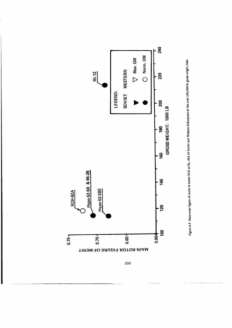
8/3/2019 Stepi Soviet 1
http://slidepdf.com/reader/full/stepi-soviet-1 242/298
m o
z _; z
I.U
'- !>©f)U.I
°°
W
/ I I:1=11/_!-.-I-=11:1l 91 =180.,I.OEI-N I'fflAI
0,,_,,
N
0
•" (3m
I,,U
0E:
8 _
qp
0
N
00
u
0
00
o
0
0
0
.<
0
0
0
232

8/3/2019 Stepi Soviet 1
http://slidepdf.com/reader/full/stepi-soviet-1 243/298
co:5,:
..5:,,
_ _ _o
o o o
IlI:I:IIAI -IO S3EIROI-I -I'IVU3AO
¢N
¢D
O
O¢N
OO
m.
=,ooo
"l-
I.U
oJr.
O
.o
O
O
Q
v-(
O
.=.
n_
.8"6,.=
.=
¢)
<
.3
o
O
..=
.El
r,
O
¢)
_O
233

8/3/2019 Stepi Soviet 1
http://slidepdf.com/reader/full/stepi-soviet-1 244/298
01,0N
&Q0N
6
E o.<1
_ o4_
N ,,_r
_,I +I
v "" _'_" _ _ _I
0
6 o0 0 0
• i
8 _
._
0
<
.__
,_
,6
IAId-I :81N1"1:3dO :liVid "lV01J.Id:IA
234

8/3/2019 Stepi Soviet 1
http://slidepdf.com/reader/full/stepi-soviet-1 245/298
The vertical climb performance of the Mi-26 appears to be almost identical to that of the Hypo
52-SR (Table 6.3 and Fig. 6.11).
According to Boeing Vertol data, the (War)hmax for the XCH-62A helicopter is 134,300 lb. This is
below the maximum flying gross weight of the aircraft. The (Wgr)VT O = 130,300 lb, and the vertical
climb rate corresponding to this weight is about 260 fpm. This rate of climb is lower than for the hypo-
thetical helicopters because of the constancy of the transmission limited power available up to the VTO
altitude of 3000 ft. At normal gross weight, Vcv = 1390 fpm, which is slightly higher than for the hypo-
thetical and the Mi-26 helicopters.
Looking at Fig. 6.11, one would get the impression that as far as vertical climb performance is con-
cerned, the Soviet helicopter designers actually improved the vertical performance capabilities of their
heavy-lift models, making them comparable to those expected for the U.S. HLH.
6.4 Energy Aspects in Hover
Table 6.4. In order to provide a common basis for the compared helicopters, the investigation of
energy aspects in hover was performed at their maximum OGE hovering gross weights at SL, ISA, except
for the Mi-26, where the maximum flying weight is lower than the SL, OGE hovering weight. As in the
preceding chapters, all of the important information required to compute the variation of hourly fuel
consumption with the indicated hovering time per pound of ideal maximum payload is indicated in Table
6.4.
Hourly Fuel Consumption per Pound of Payload in Hover OGE, at SL, ISA (Fig. 6.12). It is evident
from Fig. 6.12 that with respect to the important criterion of energy consumption per unit weight of
payload in hover, the Mi-12 helicopter definitely shows poor performance. This is especially visible when
compared with the XCH-62A curve.
Similar to other comparisons, as witnessed by the Hypo 52-SR and Hypo 52-SBS models, it is also
evident that Soviet designers have been striving to achieve energy consumption per unit of payload com-
parable to that of their Western counterparts and, in the case of the Mi-26, have succeeded.
6.5 SHP Required in Level Flight at Sea Level
Establishment of the (SHP/Wgr) = f(V) Relationship. Since comparison of forward flight aspects is
performed at maximum flying weights, the (SHP/War) = f(V) relationship must be established for all of
the compared helicopters at that particular gross weight. For the XCH-62A helicopter with no external
load, the SHP = f(V) curves at sea level, 95°F were available (Fig. 6.13). Using an approach identical to
that applied to the CH-47D in Section 5.5, the basic inputs needed for calculating (SHP/Wg r) = f(V) at SL,
ISA were found (Table 6.5). From this table it can be seen that the f and c-d values computed for both
235

8/3/2019 Stepi Soviet 1
http://slidepdf.com/reader/full/stepi-soviet-1 246/298
0.5
i 0.4
=" 0.3Z0
i-a.
zO 0.2¢.)
,.Iw
I,I.
>...I
0.1O
Mi-26Hypo-52-SBS "_
.._..R===.r___'_"_it_'_H y po.52.SR
0 2"0 4'0 60
HOVER TIME: MINUTES
Figure 6.12 Variation with time of hourly fuel consumption per pound of ideal maximum payload in hover OGE at
SL, ISA for Soviet and Western helicopters of the over lO0,O00-1b gross weight class.
236

8/3/2019 Stepi Soviet 1
http://slidepdf.com/reader/full/stepi-soviet-1 247/298
TABLE.4
ENERGY ASPECTS IN HOVER AT S/L, ISA
OVER 100,000-LB GROSS WEIGHT CLASS
ITEM
GROSS WEIGHT: LB
Overall Figure of Merit
SHP Required in Hover: hp
T.O SHP Installed: hp
SHPreq/SHPTO
sfc: Ib/hp-hr
Hourly Fuel Flow per Pound
of GW: Ib/hr-lb
Zero Time Payload: Ib
Ratio of Zero Time PL to GW
Hourly Fuel Flow per Lb of PLfor t = 0: Ib/hr-lb
t = 1/3 hr
t = 2/3 hr
t=lhr
Mil V-12
Mi-12
Hypothetical
Hypo 52-SR
HELICOPTER
Hypothetical
Hypo 52-SBS
Mil
Mi-26
197,600
0.618
26,000
26,O00
1.0
0.63
0.0831
54,300
0.275
0.302
0.336
0.378
0.432
131,375
0.562
23,250
23,25O
1.0
0.44
0.0779
65,200
0.496
0.157
0.166
0.175
0.186
123,480
0.555
22,140
22,480
0.98
0.44
0.0782
60,270
0.488
0.160
0.171
0.181
0.193
129,210
0.620
20,000
20,000
1.0
0.47
0.0727
59,050
0.457
0.159
0.168
0.178
0.188
Boeing Vertol
XCH-62A
134,300
0.635
17,700
24,240
0.73
0.50
0.0659
68,750
0.512
0.129
0.135
0.141
0.148
TABLE 6.5
EQUIVALENT FLAT PLATE AREAS AND AVERAGE BLADE PROFILE COEFFICIENTS
(BASED ON FIGURE 6.13)
ITEM
/¢indf 8t Vine x
kindf at Ve
hvf at Vma x
hvf at Vo
GROSS WEIGHT: LB
148,000 118,000
ASSUMED VALUES
1.8 1.8
1.7 1.7
1.03 1.03
1.04 1.04
_oa 0.96 0.96|1
COMPUTED VALUES
Wfp : psf
f: sq.ft
612.0
241.8
1/71.7
0.60
0.0084
514.2
229.5
1/58.4
0.48
0.0082
237
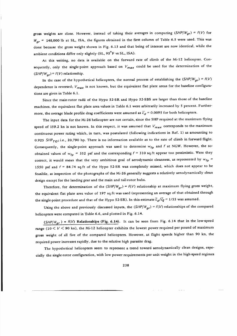
8/3/2019 Stepi Soviet 1
http://slidepdf.com/reader/full/stepi-soviet-1 248/298
gross weights are close. However, instead of taking their averages in computing (SHP/Wgr) = f(V) for
Wgr = 148,000 lb at SL, ISA, the figures obtained in the first column of Table 6.5 were used. This was
done because the gross weight shown in Fig. 6.13 and that being of interest are now identical, while the
ambient conditions differ only slightly (SL, 95°F vs SL, ISA).
At this writing, no data is available on the forward rate of climb of the Mi-12 helicopter. Con-
sequently, only the single-point approach based on Vma x could be used for the determination of the
(SHP/Wg r) = f(V) relationship.
In the case of the hypothetical helicopters, the normal process of establishing the (SHP/Wg r) = f(V)
dependence is reversed; Vma x is not known, but the equivalent flat plate areas for the baseline configura-
tions are given in Table 6.1.
Since the main-rotor radii of the Hypo 52-SR and Hypo 52-SBS are larger than those of the baseline
machines, the equivalent flat plate area values in Table 6.1 were arbitrarily increased by 5 percent. Further-
more, the average blade profile drag coefficients were assumed as Ta = 0.0095 for both helicopters.
The input data for the Mi-26 helicopter are not certain, since the SHP required at the maximum flying
speed of 159.2 kn is not known. In this respect, it was assumed that Vma x corresponds to the maximum
continuous power rating which, in turn, was postulated (following indications in Ref. 1) as amounting to
0.925 SHPTo; i.e., 20,790 hp. There is no information available as to the rate of climb in forward flight.
Consequently, the single-point approach was used to determine wtp and f at NGW. However, the so-
obtained values of wto = 352 psf and the corresponding f = 310 sq.ft appear too pessimistic. Were they
correct, it would mean that the very ambitious goal of aerodynamic cleanness, as represented by wtp =
1550 psf and f = 84.74 sq.ft of the Hypo 52-SR was completely missed, which does not appear to be
feasible, as inspection of the photographs of the Mi-26 generally suggests a relatively aerodynamically clean
design except for the landing gear and the main and tail-rotor hubs.
Therefore, for determination of the (SHP/Wor) = f(V) relationship at maximum flying gross weight,
the equivalent flat plate area value of 197 sq.ft was used (representing an average of that obtained through
the single-point procedure and that of tile Hypo 52-SR). In this estimate CO/_ = 1/55 was assumed.
Using the above and previously discussed inputs, the (SHP/Wg r) = f( V) relationships of the compared
helicopters were computed in Table 6.6, and plotted in Fig. 6.14.
(SHP/Wgr) = f(V) Relationships (Fig. 6.14). It can be seen from Fig. 6.14 that in the low-speed
range (10 < V < 90 kn), the Mi-12 helicopter exhibits the lowest power required per pound of maximum
gross weight of all five of the compared helicopters. However, at flight speeds higher than 90 kn, the
required power increases rapidly, due to the relative high parasite drag.
The hypothetical helicopters seem to represent a trend toward aerodynamically clean designs, espe-
cially the single-rotor configuration, with low power requirements per unit weight in the high-speed regimes
238
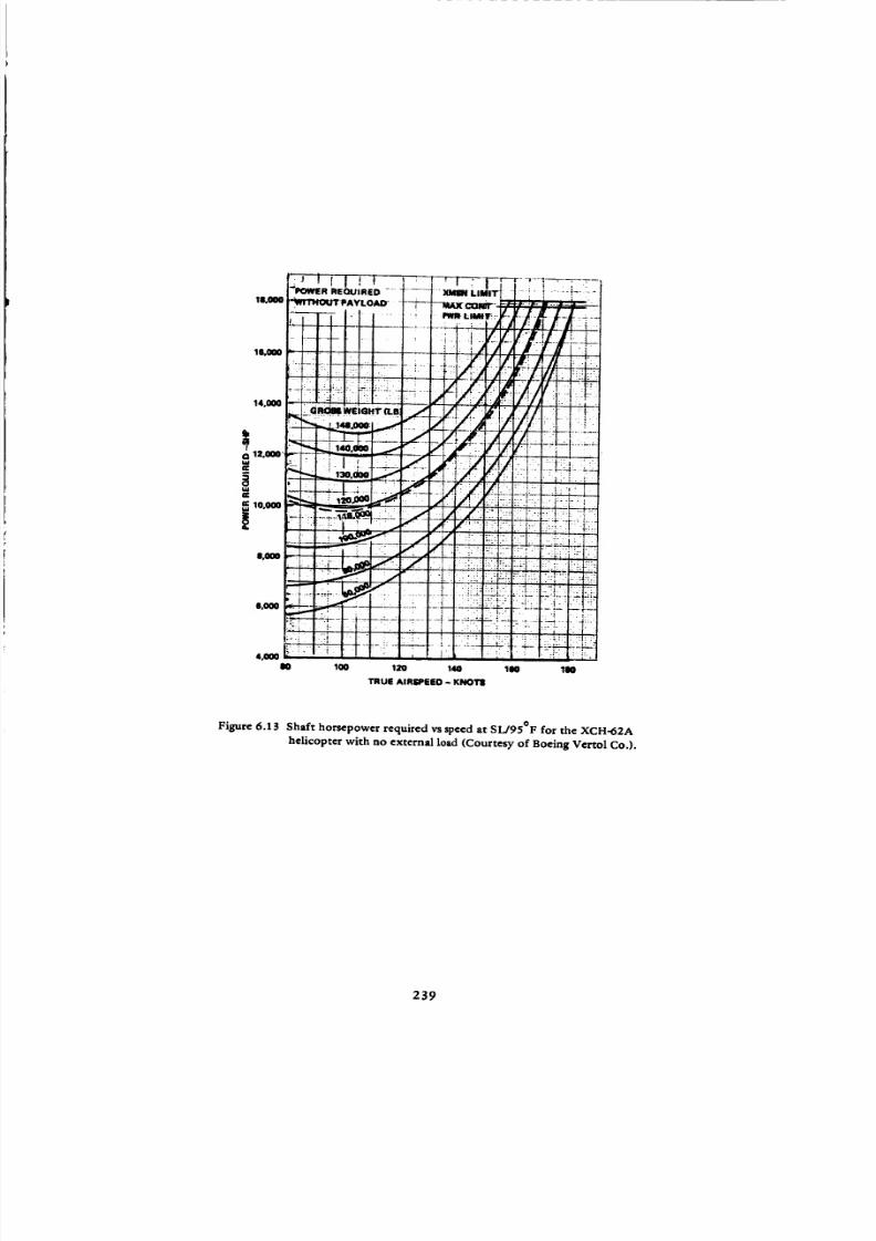
8/3/2019 Stepi Soviet 1
http://slidepdf.com/reader/full/stepi-soviet-1 249/298
le0o00
_L_O
14,000
12,000"
10,000
UO0
e,o00
4,000Im 100 120 140 100 100
TRUE AIRSPEED- KNOTS
Figure 6.13 Shaft horsepower required vs speed at SL/95°F for the XCH-62A
helicopter with no external load (Courtesy of Boeing Vertol Co,).
239

8/3/2019 Stepi Soviet 1
http://slidepdf.com/reader/full/stepi-soviet-1 250/298
ITEM
GROSS WEIGHT; LB
rtoa Estimate at Vma x or Vcr
Vma x or Vet; kn
SHP; hp
_Main Rotor RHP; hp
Main Rotor Vt; fps
Torque Compensating Thrust; Ib
Tail Rotor Disc Loading; psf
Tail Rotor _£
Tail Rotor _'d
Tail Rotor _d/ff_
Tail Rotor Power; hp
RHPtr/RHPmr
_loa at Vma x or Vcrma x
(SHP/VVg r) = f(V): 1st Approximation
Mta b at Vma x or Vcrma x
/_ at Vma x or Vcrmax;
Main Rotor Disc Loading; psf
Main Rotor ct
Main Rotor Cd
Main Rotor C,d/_
kvf
k/ndf
Computed wf; psf
Equivalent Flat Plate f; sq,ft
Computed Ve; kn
Computed SHPmin; hp
MAX. GROSS WEIGHT; LB
(SHP/Wgr); hp/Ib at F; kn
SL/ISA
0
40
60
80
100
120
140
160
TABLE 6.6
FORWARD FLIGHT ASPECTS AT SL, ISA
OVER 100,000-LB GROSS WEIGHT CLASS
Mil V-12
Mi-12
213,860
140.0
[22,200]
721.4
0.951
0.858
0.320
11.18
0.595
[0.0095]
1/62.7
1.02
1.10
5O8
420
81.4
13,790
Hypothetical
Hypo 52-SR
131,375
[21,500]
690
HELICOPTER
Mil
M i-26
109,148
159.2
[20,794]
[690]
Hypothetical
Hypo 52-SBS
129,210
[ 18,500]
690
,m
Boeing-Vertol
XCH-62A
148,000
157.0 t
17,700
0.891 [0.891 0.951
14.26
0.55
[0.0092]
1/60
1.02
1.15
15501
84.741
0.859
0.390
12.61
0.52
[0.0092]
1/56.5
1.02
1.15
352 t?)
310 (._)
13.27
0.60
0.0095]
1/63.4
1.02
1.10
922,91
140.11
750
[0.95]
0.910
0.354
11.13
0.60
0.0084
1/71.7
F
231,500 131,375 123,480 129,210 148,000
0.1793
0.1296
0.0974
0.0864
0.0867
0.0954
0.1121
0.1367_
_4
0.1548 0.1385
0.1081 0.1076
0.0806 0.0932
0.0700 0.0880
0.0685 0.0871
0.0731 0.0940
0.0831 0.1093
0.0981 0.1320
1.04 to 1.03
1.5 to 1.8
612
241.8
97.1
12_80
0.1426
0.0949
0.0739
0.0685
0.0729
0.0849
0.1056
0.1770
0.1268
0.0932
0.0785
0.0734
0.0759
0.0787
0.0878
rI
NOTES:
* Based on Figure 6.13
**Based on f= 197 sq.ft, and _d/_t = 1/55
Assumed or rough estimated values are shown in brackets [ ].
"rAt SL, 95°F
240

8/3/2019 Stepi Soviet 1
http://slidepdf.com/reader/full/stepi-soviet-1 251/298
rn
..Ir_.'1=.
"I"
UJ
O3OCI:
14.O
G]Z
0
n-uJ
"I"
SPEED OF FLIGHT: KN
Figure 6.14 Comparison of shaft horsepower per pound of gross weight vs speed of level fl ight at SL/ISA
of Soviet and Western helicopters of the over 100,000-1b gross weight class.
241
8/3/2019 Stepi Soviet 1
http://slidepdf.com/reader/full/stepi-soviet-1 252/298
of flight. Also, their (IV/De)ma x values appear to be the highest for the considered class. By contrast,
in the very low-speed regimes of horizontal flight, the high disc loading of the hypothetical machines
(especially at their maximum flying weights) leads to more elevated per-unit-weight power requirements
than for the Mi-12 and XCH-62A helicopters.
Because of the previously discussed uncertainty regarding the SHP required at Vma x for the Mi-26,
the (SHP/Wg r) = f(I/) curve should be considered as approximate. However, the goal of aerodynamic
cleanness set up in the Hypo 52-SR has probably not been achieved and consequently, at V > 60 kn, the
power required per pound of gross weight of the Mi-26 begins to deviate from that of the hypothetical
single-rotor helicopter and becomes similar to that of the XCH-62A.
With respect to the comparison of the (SHP/IVg r) = f(I/) curves of the XCH-62A and Mi-12 heli-
copters, it should be recalled that the curve of the XCH-62A was based on wind-tunnel supported manu-
facturer's data, while that of the Mi-12 was reconstructed from a single, and not even completely certain,
pair of SHP, Vine x values. The (SHP/Wg r) = f(V) relationship of the hypothetical helicopters appear to be
more as design objectives than characteristics of actual rotorcraft.
6.6 Energy Aspects in Level Flight at SL, ISA
Fuel Required per Pound of Gross Weight. The numerical inputs required for a determination of
fuel required per pound of gross weight and hour, and 100 n.mi are given in Table 6.7, while the results
are graphically shown in Figs. 6.15 and 6.16.
One can see from Fig. 6.15 that the high specific fuel consumption of the Mi-12 engines overbalances
any advantages in the (SHP/Wg r) levels, even in the low-speed region, resulting in the highest hourly fuel
requirements per pound of gross weight throughout the whole speed range.
It is evident from Fig. 6.16 that this fuel requirement per unit of gross weight of the Mi-12 when
referred to 100 n.mi of flight distance also remains higher than that of the other compared helicopters.
The fuel requirements of the hypothetical helicopters at V > 50 kn, referred to both time of flight
and distance, seem to be approximately on the same level as those of the XCH-62A model, while for the
Mi-26, they are even closer to those of the U.S. HLH type.
Fuel Requirements per Pound of Zero-Range Payload. Similar to the preceding case, the numerical
inputs are shown in Table 6.8, while the results are graphically presented'in Figs. 6.17 and 6.18. It can be
seen from the first of these figures that due to a less favorable weight-empty to gross-weight ratio of the
Mi-12 helicopter, the gap between the fuel requirements per pound of zero-range payload and hour for
this machine and those of the others becomes even wider than that shown in Fig. 6.15. In General, the
XCH-62A helicopter represents the lowest fuel requirements per pound of zero-range payload and hour.
242

8/3/2019 Stepi Soviet 1
http://slidepdf.com/reader/full/stepi-soviet-1 253/298
TABLE 6.7
RELATIVE FUEL REQUIREMENTS WITH RESPECT TO GROSS WEIGHT
OVER 100,000-LB GROSS WEIGHT CLASS
ITEM
HELICOPTER
Mil V-12
Mi-12
Hypothetical
Hypo 52-SR
Mil
M i-26
Hypothetical
Hypo 52-SBS
Boeing-Vertol
XCH-62A
(SHPTO/Wgr): hp/Ib 0.1123 0.1770 0.1821 0.1548 0.1638
SPEED OF FLIGHT: KN RATIO OF SHP REQUIRED TO T.O: SHP
0
40
60
80
100
120
140
160
SPEED OF FLIGHT: KN
0
40
6O
8O
100
120
140
160
SPEED OF FLIGHT: KN
0
40
6O
80
100
120
140
160
SPEED OF FLIGHT: KN
40
60
80
100
120
140
160
i
NOTE: Assumed or rough
[1.270]
0.845
0.658
0.586
0.649
0.756
0.940
1.0
0.716
0.527
0.445
0.415
0.429
0.445
0.496
SPECIFIC
"0.985"
0.712
0.535
0.474
0.476
0.524
0.616
_0.751.
1.0
0.698
0.521
0.454
0.443
0.472
0.537
0.634
0.846
0.556
0.569
0.538
0.532
0.579
0.643
0.813
FUEL CONSUMPTION: LB/SHP-HR
[0.62]
0.66
0.725
0.75
0.73
0.69
0.64
0.44
0.48
0.525
0.56
0.58
0.565
0.560.54
0.44
0.45
0.50
0.52
0.52
0.50
0.470.45
0.47
0.51
0.55
0.59
0.595
0.58
0.5450.52
0.47
0.48
0.49
0.495
0.49
0.485
0.48
0,47
FUEL CONSUMPTION PER HOUR AND POUND OFGW: LB/HR-LB
[0.0884]
0.0626
0.0536
0.0514
0.0532-
0.0586
0.O676
0.0779
0.0609
0.0489
0.0441
0.0426
0.0429
0.0441
0.0474
0.0782
0.0583
0.0487
0.0451
0.0451
0.0477
0.0523
0.0615
0.0728 0.0651
0,0551 0.0516
0.0414 0.0457
0.0431 0.0436
0.0408 0.0422
0.0424 0.0456
0.0453 0.0525
0.0510 0.0620
0.1566
0.0893
0.0642
0.0532
0.0488
0.0483
FUEL REQUIRED PER POUND OF GW AND 100 N.Mi
0.1458
0.0812
0.0564
0.0451
0.0398
0.0376
0.0385
estimated values are shown in brackets [ ].
0.1378
0.0739
0.0517
0.0408
0.0353
0.O324
0,0319
i
0.1290
0.0761
0.0545
0.0422
0.0380
0.0375
0,0388
I
0.1521
0.0816
0.0562
0.0426
0.0357
0.0315
O.0296
243

8/3/2019 Stepi Soviet 1
http://slidepdf.com/reader/full/stepi-soviet-1 254/298
24.4.

8/3/2019 Stepi Soviet 1
http://slidepdf.com/reader/full/stepi-soviet-1 255/298
I
|_gwgwg||Igu||_Wwwl
"!tq'N OOi-ltl/fll :!W'N OOi _i tl9 -iO ONl'lOd ttgd 131"1=1
0
0
0iIik
li.
245
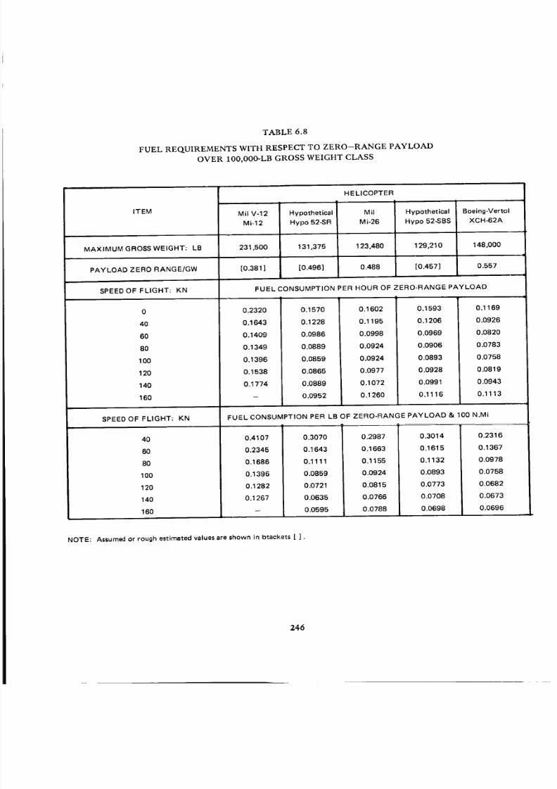
8/3/2019 Stepi Soviet 1
http://slidepdf.com/reader/full/stepi-soviet-1 256/298
TABLE 6.8
FUEL REQUIREMENTS WITH RESPECT TO ZERO--RANGE PAYLOAD
OVER IO0,O00-LB GROSS WEIGHT CLASS
ITEM
HELICOPTER
Mil V-12
MS-12
Hypothetical
Hypo 52-SR
Mil
M i-26
Hypothetical
Hypo 52-SBS
Boeing-Vertol
XCH-62A
MAX IM UM GROSS WEIGHT: LB 231,500 131,375 123,480 129,210 148,000
PAYLOAD ZERO RANGE/GW [0.381 ] [0.496] 0.488 [0.457] 0.557
SPEED OF FLIGHT: KN
0
40
60
80
100
120
140
160
SPEED OF FLIGHT: KN
FUEL CONSUMPTION PER HOUR OF ZERO-RANGE PAYLOAD
0.2320
0.1643
0.1409
0.1349
0.1396
0.1538
0.1774
0.1570
0.1228
0.0986
0.0889
0.0859
0.0865
0.0889
0.0952
0.1602
0.1195
0.0998
0.0924
0.0924
0.0977
0.1072
0.1260
0.1593 0.1169
0.1206 0.0926
0.0969 0.0820
0.0906 0.0783
0.0893 0,0758
0.0928 0.0819
0.0991 0.0943
0.1116 0.1113
40
60
8O
100
120
140
160
FUEL CONSUMPTION PER LB OF ZERO-RANGE PAYLOAD & 100 N.Mi
0.3070
0.1643
0.1111
0.0859
0.0721
0.0635
0.0595
0.2987
0.1663
0.1155
0.0924
0.0815
0.O766
0.0788
0.3014
0.1615
0.1132
0.0893
0.0773
0.0708
0.O698
0.2316
0.1367
0.0978
0.0758
0.0682
0.0673
0.0696
0.4107
0.2345
0.1686
0.1396
0.1282
0.1267
NOTE: Assumed or rough estimated values are shown in brackets [ ].
246

8/3/2019 Stepi Soviet 1
http://slidepdf.com/reader/full/stepi-soviet-1 257/298
,A
7-, i/ _"='_
_'11 / / l '/I
,)t_ I o
I ! N
p I
/ tI i
-., i , i , , , . ' II , 'l , i i " I ' , , i 0
I.l"l 0 I,I'2N ,- 0 I.O 0
'-- 0
8-1"ldH/8-1:'ld::IONVU'OEI3Z dO GNnOa • UFIOH U3a o31=11n031=1 l=ln=l
0
"r'o
o
u
E
U
0
<
0
0
0
0
e_
r_
247
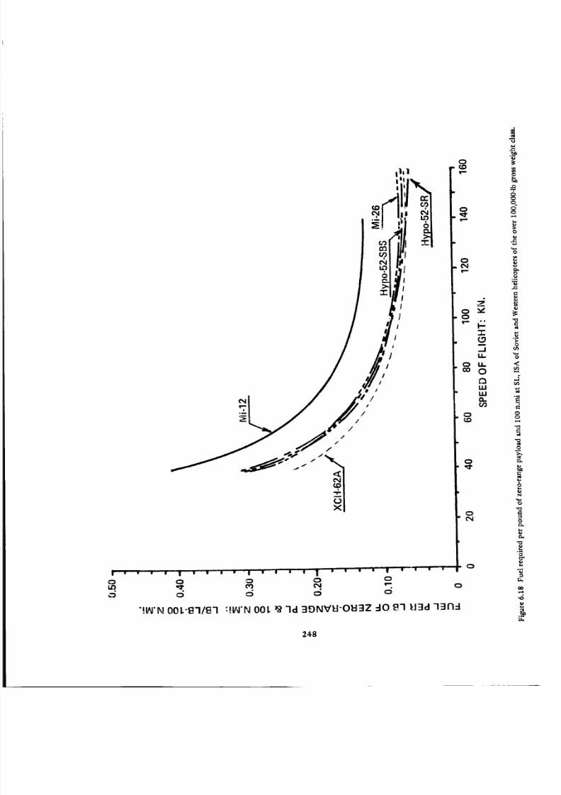
8/3/2019 Stepi Soviet 1
http://slidepdf.com/reader/full/stepi-soviet-1 258/298
o1,0
o
o
! r • • I | I • e • "| • l • I | • • e • II g I • 0
o o o o o
c_ o o o
"!I_'N 00L-13-111_'I :!II_'N 00L _ -Id 3E)NVI=I-OEI3Z -IO _'I IJ3d -l_Jl'l -I
o
.JLI.
O U.O
LULJJa.C/)
O
O
Oe_l
O
O
O
O
OO
,-4
O
°_
-G,J=
O
_r_
C_
O
.o
O
00
248

8/3/2019 Stepi Soviet 1
http://slidepdf.com/reader/full/stepi-soviet-1 259/298
The hypothetical helicopters exhibit appreciably higher payload-related fuel requirements than those
of the XCH-62A in the low-speed regimes of flight; but at high flying speeds, their energy expenditure
per pound of payload appear almost as good, and in the case of the hypothetical single-rotor configuration,
even slightly better than those of the American HLH.
With respect to the Mi-26, it appears that the payload-related fuel consumption goals, as set by the
Hypo 52-SR, were closely met except for some possible deviations in the high cruise speed area.
The above-mentioned observations are further supported by the graphs of payload-related fuel re-
quirements referred to flight distance shown in Fig. 6.18.
Fuel Required per Pound of Payload vs Distance (Table 6.9). The trend in fuel requirements with
respect to unit of weight of the zero-range payload is also confirmed by the calculations presented in
Table6.9, and graphically depicted in Fig. 6.19.
A glance at this figure would indicate that the energy requirements for transporting a pound of pay-
load in the Mi-12 over various distances is twice as high as those of the two hypothetical helicopters, the
Mi-26, and the XCH-62A.
6.7 Productivity
Productivity Index. Similar to Sections 4.6 and 5.7, the productivity index, calculated from Eq.
(1.17a), is based on either specified (Mi-12, Mi-26, and XCH-62A) or assumed (hypothetical helicopters)
maximum cruising speed values. The necessary inputs for those calculations are shown in Table 6.10, with
the results presented in Fig. 6.20. It can be seen from this figure that the PI values (at maximum flying
gross weights) of the XCH-62A helicopter are the highest, while those of the Mi-12 are the lowest (about
one-third that of the HLH level). The hypothetical helicopters, although clearly superior to the Mi-12 in
this respect, appear inferior to the XCH-62A. It should be remembered, however, that in the determina-
tion of PI values, the payload level is of prime importance and this, in turn, depends on the maximum
flying weight determination. The maximum gross weight of 148,000 lb for the HLH was solely based on
the maneuvering factor level of n = 2.0. Therefore at the transmission limit of 17,700 hp, this helicopter
has no hovering capability at SL, ISA; while for the hypothetical helicopters, Wgrmax was arbitrarily
established as maximum gross weights corresponding to hovering OGE at SL, ISA. For this reason, the
PI values for the XCH-62A are also shown at its maximum hovering weight of 134,300 lb. It can be seen
from Fig. 6.20 that the productivity index of the HI, H becomes almost identical with that of the single-
rotor hypothetical helicopter.
The productivity index of the Mi-26 at its maximum flying weight (which is lower than the SL, OGE
hovering weight) appears to be slightly below that of the Hypo 52-SR.
249

8/3/2019 Stepi Soviet 1
http://slidepdf.com/reader/full/stepi-soviet-1 260/298
TABLE 6.9
FUEL REQUIRED PER POUND OF PAYLOAD AT VARIOUS DISTANCES
OVER 100,000-LB GROSS WEIGHT CLASS
ITEMMil V-12
Mi-12
HELICOPTER
Hypothetical
Hypo 52-SR
Mil
Mi-26
Hypothetical
Hypo 52-SBS
Boeing-Vertol
XCH-62A
MAXIMUM GROSS WEIGHT: LB 231,500 131,375 123,480 129,210 148,000
[0.0595].1267 0.0766pt. Fuel Consumed per Lb of Zero-
Range PL and 100 N.Mi[0.0698]
FUEL REQUIRED PER POUND OF PAYLOADISTANCE: N.Mi
0.0696
0
5O
100
150
2O0
250
0
0.0678
0.1456
0.2353
0.3405
0.4652
0
• 0.0309
0.0638
0.0989
0.1364
0.1765
0
0.0398
0.0829
0.1129
0.1809
0.2368n
- 0
0.0363
0.0753
0.1173
0.1628
0.2121
0
0.0360
0.0748
0.1166
0.1617
0.2110
TABLE 6.10
PRODUCTIVITY INDEX AT Verma x AT SL, ISA
OVER IO0,000-LB GROSS WEIGHT CLASS
ITEM
HELICOPTER
Mil V-12
Mi-12
Hypothetical
Hypo 52-SR
Mil
Mi-26
Hypothetical
Hypo 52-SBS
Boeing-Vertol
XCH-62A
L
MAXIMUM GROSS WEIGHT: LB 231,500 [131,375] 123,480 [129,210] 148,000
_613
0.381
130
0.063
"0.499_
o.496145 J
0.045
_504
0.488
137.6
0.052
-0.538"
0.457
. 145 .
0.046
w_/wgr
(WpPolWgr
Vcrmax: kn
FF at Vcrma x (Ib/Ib-100 N . M i)
FLIGHT DISTANCE: N.Mi PRODUCTIVITY INDEX AT Vcrmax: LB-N.Mi/LB-HR
133.4
119.2
105.0
123.2
110.8
98.4
0
100
200
80.8 144.2
67.4 131.1
54.1 118.0
_438
0.557
135
0.050
171.6
156.3
140.9
NOTE; Assumed or rough estimated values are shown in brackets [ ].
250

8/3/2019 Stepi Soviet 1
http://slidepdf.com/reader/full/stepi-soviet-1 261/298
\
0 0 0
8"1/0"1
0
"'Id 40 8"I l:Fld 011:1117011:113n4
0
I'4
oo
0
0
m
Z
LiioZ
l-e'J
t_
I-"I-
ra-J
80
e_
oo
o
8
e_
g
0
m
g
0
251

8/3/2019 Stepi Soviet 1
http://slidepdf.com/reader/full/stepi-soviet-1 262/298
v;
u
0
.D
00
0
0
8
E
0
<
,4
>
:g
252

8/3/2019 Stepi Soviet 1
http://slidepdf.com/reader/full/stepi-soviet-1 263/298
6.8 General Discussion and Concluding Remarks
It should be emphasized that as of this writing, some important uncertainties regarding the principal
characteristics and performance of the Mi-12 and Mi-26 still exist.
For instance, the Mi-12 weight empty of 142,000 lb was based on the statement (see Appendix to
this chapter) by the chief pilot of the Mi-12 that at 105 m.ton gross weight (231,480 lb), the aircraft has
a useful load of 40 tons (88,180 lb). The weight-empty value, computed from the record flight to 2250
meters with a crew of six and 88,633 Ib of payload, is somewhat lower. This record flight was presumably
accomplished at Wgrmax -- 105 m.ton -- 231,500 lb using a running takeoff (see Appendix to this chapter,
and Ref. 1). Also assuming that the amount of fuel at takeoff was for one-half hour at maximum con-
tinuous power; i.e., about 6700 lb, the weight empty would amount to 134,850 lb. However, it is not
clear whether the aircraft was loaded above its maximum gross weight, taking advantage of "something
better than standard day conditions" (see Appendix). Because of these uncertainties, the weight empty
of 142,000 Ib was assumed for the Mi-12 in this study.
One should also remember that for the sake of simplicity, the rotor unloading by the wing in high-
speed flight was neglected. This appears to be permissible in view of other uncertainties and relatively
small differences in the (SHP/Wg r) = f(t0 values obtained for the winged and pure helicopter configura-
tions of the Mi-6.
There are also some uncertainties regarding the VTO gross weight. Tishchenko indicated (see Appen-
dix to this chapter) that "The nominal 20 re.ton (44,092 lb) payload is based on HOGE at 1000 m (3,280
ft) standard day conditions; fuel for 510 km (275.2 n.mi); and 5 percent fuel reserve."
Assuming FFw-- 0.05 Ib/Ib-100 n.mi (Fig. 6.16) and an average gross weight of 190,000 lb, the fuel
required for 275 n.mi, with 5 percent reserve, would be 24,880 lb. For the specified crew of six, and an
assumed weight empty of 134,850 lb, the gross weight allowing the helicopter to hover OGE at 1000m
ISA would still be 205,150 lb, while the VTO gross weight (corresponding to hover OGE at 3000 ft ISA-
close to 1000 m) determined in Section 6 -amounts to 195,000 lb. Should the WgrVTO -- 195,500 lb
(Table 6.3) be correct, then the corresponding weight empty would amount to only 125,200 lb.
It is obvious that the difference of 142,000- 125,200 = 16,800 lb would have a noticeable influence
on all figures related to payload in general; for instance, the fuel requirements per pound of zero-range
payload would be lower by about 19 percent, while the relative productivity would be higher by about 35
percent. This, of course, would make the Mi-12 somewhat more attractive with respect to other helicopters
considered in the over 100,000qb gross weight class. Nevertheless, it would not alter the overall conclusions
derived below on the basis of the assumed weight empty of 142,000 lb.
From the comparison of the Mi-12 helicopter with the XCH-62A, it appears that the overall design
effectiveness of the Soviet machine is not as high as its American counterpart, in spite of the fact that
253

8/3/2019 Stepi Soviet 1
http://slidepdf.com/reader/full/stepi-soviet-1 264/298
aerodynamically, in the approximate 10 to 145-kn flying speed interval, the Mi-12 shows advantages over
the American HLH as witnessed by the SHP required per pound of gross weight (Fig. 6.14).
However, these advantages are offset by the higher structural weight of the Mi-12. For instance, at its
'official' maximum flying weight of 231,500 Ib, the zero-range payload of the Mi-12 is 88,200 lb, which is
practically the same as that of the XCH-62A (88,470 lb) at a flying gross weight of only 148,000 lb. As a
further consequence of the high structural weight aspects, the Mil helicopter when operating close to its
maximum flying weight is underpowered, in spite of the total installed takeoff power of 26,000 hp. In
order to hover OGE at SL, ISA, its gross weight must be reduced to about 198,000 lb, with the zero-range
payload dropping to about 54,500 lb; while under the same circumstances, the XCH-62A helicopter with
its transmission-limited power of I7,700 hp, should have a zero-range payload of about 74,800 lb.
The consequences of the high structural weight of the Mi-12 are visible in all subsequent comparisons
of this aircraft with the American HLH when energy requirements are related to the unit weight of the
payload (see corresponding figures); and is equally visible in the comparison of the productivity index (Fig.
6.20).
Apparently, the Soviet designers realized the above-mentioned deficiencies of the Mi-12 and tried to
eliminate them in their future designs of heavyqift helicopters. This trend is clearly visible in the so-called
hypothetical helicopters of the 52-re.ton design gross weight (very similar to the design gross weight of
approximately 53.5-m.ton for the XCH-62A), and was fully confirmed in the manufacturer's figures for
the Mi-26.
As previously mentioned, although there are some uncertainties regarding the Mi-26 SHP value re-
quired at Vmnx. This in turn casts some doubt with respect to the (SHP/Wg r) = f(11') relationship and thus,
on all subsequent computations as well. Nevertheless, on the basis of 'solid' manufacturer's figures regarding
weights and hovering performance, plus the more speculative ones related to forward flight aspects, it may
be determined that most of the weight and performance objectives as represented by the single-rotor
52-ton hypothetical helicopter have been met.
The new D-136 turboshaft, with its Western-level sfc and specific weight values, undoubtedly repre-
sents one of the most important factors in the success of the Mi-26 in attaining the design goals set for
the hypothetical helicopters.
Should the operational and flying qualities aspects of the Mi-26 be as good as its weights and per-
formance aspects, then the Soviets will have a helicopter that could prove highly competitive with the
American HLH.
254
8/3/2019 Stepi Soviet 1
http://slidepdf.com/reader/full/stepi-soviet-1 265/298
APPENDIX - CHAPTER 6
EXERPTS FROM BOEING-VERTOL REPORT No. D210-10301-1
"A DESCRIPTION OF THE Mil V-12 TRANSPORT HELICOPTER"
by T. R. Pierpoint
June 30, 1971
INTRODUCTION
The USSR brought a M1L B-12 helicopter (sometimes referred to as the Mil V-12) to the 1971 Paris Air
Show which took place at Le Bourget Airport, Paris, France, between 27 May and 6 June. This report
has been prepared to summarize what was learned from examinations of the helicopter and from discussion
with various USSR personnel.
Through Mr. Igor S. Gouriev who was the Director of the USSR Exposition at the Air Show, contact was
made with Mr. Marat Tishchenko who is the new chief designer and head of the Moscow helicopter plant
MIL because he replaced Mr. Mil as Chief Designer upon Mr. Mil's death in January 1971.
Two extended sessions were held. The first consisted of a several hour long inspection of the aircraft
itself on 1 June 1971.
A. From the USSR:
Mr. Marat N. Tishchenko .................. Chief of the M.L. Mil Moscow Helicopter Plant
Mr. B. A. Koloshenko ................................ Mil V-12 Chief Test Pilot
Mr. Leonid Maslov .................................. Chief, Rotor Head Design
Mr. Nicolay Drobroljubov ............................ Automatic Systems Designer
Mr. Anatoly A. Sokolov ................................ Mil-6, 8 & 10 Test Pilot
Mr. Pelevin ............................................... Mil-8 Pilot
and several others
B. From Boeing and Agusta:
Mr. Howard N. Stuverude ......................... Vice President & General Manager
Vertol Division, The Boeing Company
Mr. Bruno Lovera .................................... Chief Design Engineer
Construzioni Aeronautiche Agusta
Mr. Fred Doblhoff ................................... Director of Engineering
Boeing International Corp., Europe
Mr. William Coffee ..................................... Boeing-Vertol Pilot
Mr. T. R. Pierpoint ................................. Director Current Programs
Boeing-Vertol
255

8/3/2019 Stepi Soviet 1
http://slidepdf.com/reader/full/stepi-soviet-1 266/298
The second session occurred on 4 June 1971 and consisted of a three to four hour technical discussion
with the following persons in attendance:
A. From the USSR:
Mr. Marat N. Tishchenko .................. Chief of the M.L. Mil Moscow Helicopter Plant
Mr. Leonid Maslov ............................................ Chief, Rotor Head Design
Mr. Anatoly A. Sokolov ........................................ Test Pilot
Mr. Nicolay Drobroljubov ............................ Automatic Systems Engineer
Mrs. Nina Artamonova ........................................ Interpreter
B. From the USA:
Mr. Howard N. Stuverude ......................... Vice President & General Manager
Vertol Division, The Boeing Company
Mr. Tadeusz Tarczynski .......................... Design Specialist, Vertol Division
Mr. T. R. Pierpoint ................................. Director Current Programs
Vertol Division
The Contents of this report have been compiled from notes provided to the writer by each of the American
participants in addition to his own. What has been written herein has been reviewed by each of the partici-
pants for accuracy and completion and therefore represent a summary of the recollections of all partici-
pants.
In the 7 or 8 hours spent with the Russians, there appeared to be absolutely no constraint on their part
to discuss technical aspects of the aircraft as well as their thoughts with respect to the future and other
aspects of VTOL aircraft. They would not however discuss how many Mil V-12 aircraft have been or will
be constructed, how many hours have been flown, the number of hours on the aircraft at the Air Show,
nor future plans. They were also vague as to whether or not the aircraft would be placed on the world-
wide commercial market and would not give an indication of its selling price. However, Mr. Bart Kelley,
of the Bell Helicopter Company was told by them that 20 helicopters are under construction, and Aviation
Week (June 7, 1971) reported that one other Mil V-12 is flying and that several hundred will be built
incorporating final design features not incorporated in the aircraft described herein.
OVERALL DESCRIPTION OF THE MIL V-12
The Mil V-12 helicopter is a giant aircraft with an overload gross weight of 105 metric tons (231,483
pounds), and a normal gross weight of 97 metric tons (213,846 pounds). It is a side by side (lateral) rotor
configuration with approximately 8.5% overlap between the 5-bladed rotors.
Each rotor is supported on a pylon-wing arrangement that is braced by large struts interconnecting to both
the landing gear and fuselage. At the end of each pylon-wing there is located a nacelle housing two engines,
rotor transmission and rotor. Each rotor is powered by two Soloviev D-25VF turboshaft engines of 6500
shaft horsepower connected to a 13,000+ hp transmission (approximately 1500 hp additional is required
for control differential purposes, so it is probable each transmission is capable of transmitting 14,500 hp)
which is directly connected to the rotor.
256

8/3/2019 Stepi Soviet 1
http://slidepdf.com/reader/full/stepi-soviet-1 267/298
The rotors are 35 meters in diameter (114.83 ft) Mil-10 rotors with modified blades. The rotors are con-
nected by a cross shaft extending from each nacelle rotor transmission to a mixing transmission located
in the upper center fuselage. This transmission permits power to be transmitted from one nacelle package
to the other in the event of a loss of one or both engines on either side.
The aft fuselage is equipped with large clam shell doors and ramp both of which are hydraulically operated.
The internal clear fuselage cross section is 4.4 meters by 4.4 meters (14.44 ft X 14.44 ft) which is the
same dimension as the Anatov 22 large turboprop transport. The Mil V-12 was specifically developed to
be used in conjunction with the AN-22.
Thus, the cabin is capable of clear straight in-loading of objects up to 28.15 meters (92.36 ft) long. Located
in the top of the fuselage shell are two I beams running the length of the cabin to which is mounted an
overhead crane electrically operated that is capable of lifting ten metric tons (22,046 pounds). Tie-down
fittings are provided generously throughout the cabin floor. A single row of troop seats that fold up against
the cabin are located on each side of the cabin. No soundproofing was mounted in the cabin area, but the
cockpit and crew areas forward were soundproofed.
The landing gear is of conventional tricycle design, with dual wheels employed for both the nose and main
wheel locations. The nose wheel swivels 360 degrees. Located on the bottom aft fuselage just ahead of the
ramp are four boggie wheels apparently installed for tail low landing purposes. Hydraulically operated
pads extend down when loading in order to provide tipping support to the fuselage. No cargo hook was
installed in the aircraft demonstrated and when questioned, the Russian engineers replied that they did
not intend to install one on this aircraft. (Conflicting information was given to Mr. Coffee by the Mil V-12
Chief Pilot, Koloshenko, who claimed there is a 16 metric ton (35,274 pound) hook available.)
The aircraft is fully equipped for instrument flight and flight under icing conditions.
It is generally accepted that this helicopter has been developed principally for the movement of military
and civil equipment up to 500 km (269.70 n.mi) from airports capable of accepting the AN-22 large turbo-
prop transport aircraft to isolated sites.
In flight, the aircraft was very quiet and it was maneuvered as one would expect with a very large aircraft,
demonstrating gentle turns (less than 30 ° bank angles), high-speed flight of approximately 260 kilometers
per hour (140.30 knots), and a quite slow reduction in air speed to a hover followed by rearward flight of
approximately 15 knots. It was flown twice during the Air Show for approximately 10 minutes each flight.
The pre-flight was observed to be several hours in length before each flight. The only thing unusual noted
in the flight was that upon starting, the No. 3 engine had a tendency to torch for quite a period of time.
It appeared to take about three minutes from the start for the rotors to come to their normal rotational
speed of 120 rpm.
Although flown at light gross weights, the rotors appeared to have more coning than would be expected
at low gross weights. From a close observation of the second slow down to hover maneuver, the aircraft
demonstrated a tendency to porpoise thus appearing to require constant longitudinal stick correction by
the pilot. Overall performance as given by the Russians is shown below.
257
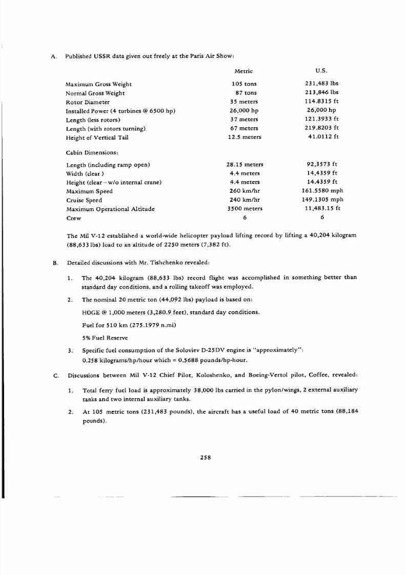
8/3/2019 Stepi Soviet 1
http://slidepdf.com/reader/full/stepi-soviet-1 268/298
A. Published USSR data given out freely at the Paris Air Show:
Maximum Gross Weight
Normal Gross Weight
Rotor Diameter
Installed Power (4 turbines @ 6500 hp)
Length (less rotors)
Length (with rotors turning)
Height of Vertical Tail
Cabin Dimensions:
Length (including ramp open)
Width (clear)
Height (clear-w/o internal crane)
Maximum Speed
Cruise Speed
Maximum Operational Altitude
Crew
Metric U.S.
105 tons 231,483 lbs
87 tons 213,846 lbs
35 meters 114.8315 ft
26,000 hp 26,000 hp
37 meters 121.3933 ft
67 meters 219.8203 ft
12.5 meters 41.01i2 ft
28.15 meters 92,3573 ft
4.4 meters 14,4359 ft
4.4 meters 14.4359 ft260 km/hr 161.5580 mph
240 km/hr 149.1305 mph
35 O0 meters 11,483.15 ft
6 6
The Mil V-12 established a world-wide helicopter payload lifting record by lifting a 40,204 kilogram
(88,633 lbs) load to an altitude of 2250 meters (7,382 ft).
B. Detailed discussions with Mr. Tishchenko revealed:
C. Discussions
1. The 40,204 kilogram (88,633 Ibs) record flight was accomplished in something better than
standard day conditions, and a rolling takeoff was employed.
2. The nominal 20 metric ton (44,092 lbs) payload is based on:
HOGE @ 1,000 meters (3,280.9 feet), standard day conditions.
Fuel for 510 km (275.1979 n.mi)
5% Fuel Reserve
3. Specific fuel consumption of the Soloviev D-25DV engine is "approximately":
0.258 kilograms/hp/hour which = 0.5688 pounds/hp-hour.
between Mil V-12 Chief Pilot, Koloshenko, and Boeing-Vertol pilot, Coffee, revealed:
1. Total ferry fuel load is approximately 38,000 lbs carried in the pylon/wings, 2 external auxiliary
tanks and two internal auxiliary tanks.
2. At 105 metric tons (231,483 pounds), the aircraft has a useful load of 40 metric tons (88,184
pounds).
258

8/3/2019 Stepi Soviet 1
http://slidepdf.com/reader/full/stepi-soviet-1 269/298
WHY THE CONFIGURATION
Mr. Tishchenko advised that the side by side configuration was selected after considerable study on their
part for the following reasons:
A. In order to reduce development costs a decision was made at the highest level to mate two Mil-10
rotors in order to obtain an overload payload of 30 metric tons (66,138 pounds) with a normal
payload of 20 metric tons (44,092 pounds).
B. When saddled with this requirement, their studies showed that 5-bladed rotors of the Mil-10 type
when placed in tandem would result in fuselage length and pylon height of such size that it would
weigh considerably more than the current design. Further, the increased drag resulting from this
configuration is, in their opinion, offset by the minimum power gains resulting from span effect
as well as from the wing which provides approximately 15-20 percent of the lift in cruise.
Incidentally, early in the first session when discussing "Why the Configuration," Tishchenko pointed
out that minimum power required for forward flight was 40% of hovering power for a lateral arrange-
ment, 50% for a single rotor arrangement, and 80% for a tandem. We objected that a tandem would
be as high as 80% and he then admitted it could be as low as 65%.
C. They also favored this configuration because of the relative ease by which they could tune the pylon
structures. When first constructed, the natural frequency of the pylon structures was close to one per
rotor rpm, and by adding additional struts they were able to tune the structure to approximately
1.5 rotor rpm. Tishchenko opined that this would have been much more difficult to accomplish with
the fuselage and pylons of a tandem configured aircraft.
When questioned whether he would have selected a tandem configuration if he were permitted to utilize
rotors optimized for the desired payload and range, his reply was that only one company in the world
had been able to consistently develop successful tandem aircraft, and that was Boeing-Vertol. He cited
the YAK-24, the Bristol Belvedere and the Bell ASW tandem aircraft as examples of unsuccessful tandem
designs and therefore he feels there must be special techniques employed in the construction of tandem
helicopters which he and other USSR designers do not possess. He did not say he would not try again,
however.
He also commented on the fact that he felt that the Chinook utilized too much overlap between the rotors
and that he personally would not employ more than about 18 or 20 percent overlap with a 4-bladed rotor
tandem. He noted that we had reduced overlap with our Model 347 from the 32% overlap in the current
3-bladed CH-47C Chinook helicopter to about 26% with increased vertical separation on the 4-bladed
Model 347 helicopter.
He felt that was a step in the right direction and probably was one of the principal reasons why the 347
is showing itself to have superior flying characteristics. The Mil V-12 employs approximately 8.5% overlap
with its 5-bladed rotors.
259

8/3/2019 Stepi Soviet 1
http://slidepdf.com/reader/full/stepi-soviet-1 270/298
Overview of Design
Chapter 7
Parameters and Performance
7.1 Introduction
Objectives and Presentation. As the comparative study progressed, it became apparent that in order
to obtain a clear picture of design trends and performance capabilities of the compared helicopters, it
would be advantageous to present each of the important comparison parameters in a specific graph, show-
ing the variation of each parameter throughout the investigated gross-weight range. Consequently, a loga-
rithmic gross-weight scale was selected as an abscissa, while the investigated parametric values were plotted
as ordinates to the usually linear and, in some cases, also logarithmic scale.
In these summary graphs, points representing individual aircraft are no longer designated by model,
but only through easy recognizable graphic symbols as shown in Tables 7.1 and 7.2 identifying the heli-
copter configuration, type of gross weight (i.e., maximum, normal, or VTOL), and type (i.e., Soviet pro-
duction, hypothetical, or Western machines).
7.2 Principal Design Parameters
Disc Loading (Fig. 7.1). The trends in disc loading values shown in Fig. 7.1 increase with gross weight
and, for the largest Western single-rotor helicopter, reaches a level of 15 psf at its maximum flying gross
weight. The disc loadings of Western tandems also exhibit growth with gross weights but, in general those
values remain below those of single-rotor machines. Soviet production helicopters, regardless of their
configuration, are characterized by lower disc loadings than their Western counterparts. By contrast, the
disc loadings of Soviet hypothetical helicopters become closer to the upper limit of the Western trend.
It is apparent that this new design philosophy is followed in actual new designs as exemplified by the
Mi-26 helicopter, whose disc loading goes up to 14.26 psf at its maximum flying weight.
Power Loading. A study of installed power loading (Fig. 7.2) would clearly indicate that values of
this design parameter in earlier Soviet helicopters are, in general, above those adopted by Western de-
signers. However, in the more recent models as the Mi-24 and Mi-26 they appear on the same level as in
their Western counterparts. In this respect, they seem to closely follow the trend established by the Tish-
chenko team in their studies of hypothetical helicopters.
260

8/3/2019 Stepi Soviet 1
http://slidepdf.com/reader/full/stepi-soviet-1 271/298
TABLE 7.1
SOVIET ACTUAL AND HYPOTHETICAL HELICOPTERS
ACTUAL
HELICOPTERS
KAMOV Ka-26
Mil Mi-2 W/Allison Engines
APPROX. MAX. GW
(LB)
7,150
7,800
Mil Mi-2
KAMOV Ka-25
Mil Mi-24D
Mil-8
Mil Mi-10K
Mil Mi-6 W/Wings
Mil Mi-26
Mil Mi-12
8,150
16,100
22,000
26,450
83,800
93,700
123,480
231,500
HYPOTHETICAL
HELICOPTERS
S.R 15 M.Ton
S. R 24 M.Ton
S.R 52 M.Ton
S.B.S 52 M.Ton
NGW/MAX. GW
(LB)
33,050/[ 37,800]
52,900/[ 58,700]
114,700/[ 131,350]
114,700/[ 129,200]
SYM BO LS
MAX. GW NORM. GW VTO GW
V
-V"
O ,&
SYMBOLS
MAX. GW NORM. GW VTO GW
261

8/3/2019 Stepi Soviet 1
http://slidepdf.com/reader/full/stepi-soviet-1 272/298
TABLE.2
WESTERN HELICOPTERS
HELICOPTERS
MBB Bo-105CB
BELL 222
AEROSPATIALE SA-365N
BELL UH-1H
SIKORSKY S-76
AE ROSPATIALE SA-330J
BOEING-VERTOL YUH-61A
SIKORSKY UH-60A
SIKORSKY CH-3E
BOEING VERTOL CH-46E
SIKORSKY CH-53D
BOEING VERTOL CH-47D
SIKORSKY CH-53E
BOEING VERTOL XCH-62A
APPROX. MAX. GW
(LB) MAX. GW
SYMBO LS
5,100 "_
7,850 !I
I8,500
9,500
10,000 '_, _'
16,300
19,700
20,250
22,050
23,300
42,000
50,000
73,500
148,000
J
V
NORM. GW
©
VTO GW
/k
262

8/3/2019 Stepi Soviet 1
http://slidepdf.com/reader/full/stepi-soviet-1 273/298
_-ISd :gNIQVOI OSI(]
b,o
0
b_
263

8/3/2019 Stepi Soviet 1
http://slidepdf.com/reader/full/stepi-soviet-1 274/298
I,LI
i ,,|, • $ ,I
O')
[>."b "©
CO 1'_ (,D 1,1')
i
dHS/'a"l :_NIGVO-I EI'=IMOd
O3
,1
I--
_,1
ZO
0'3
cOZ
rr
ILl
0ZI,Ll
r_
--J
0El
>-
UJ
00
Jtl
F-
0Z
w
Oo¢y
0tO
0
0
0cO
0
0
0t'y
0
0
OOO
¢.:"t-O
l,U
N
0
0
_o
0
eL
N
&
264

8/3/2019 Stepi Soviet 1
http://slidepdf.com/reader/full/stepi-soviet-1 275/298
Tip Speed. It appears that a tip speed of about 700 fps represents an average value for both Soviet and
Western designs (Fig. 7.3). However, for smaller helicopters, Western designers seem to favor tip speeds
values slightly higher than 700 fps, while those of Soviet designers appear to be noticeably lower. For large
helicopters, both design schools seem to agree that tip speeds of 720 to 750 fps are most feasible.
Advancing-Tip Mach Numbers and Advance Ratios. It can be seen from Fig. 7.4 that conventional
helicopters - regardless of their national origin - still encounter the old Mrab- I_ barrier. At fast cruise,
•.he advancing tip Mach number does not usually go above hhe M = 0.9 level, while almost all of the advance
ratio values appear to be included within the 0.3 to 0.4 band.
Equivalent Flat Plate Area Loading. The absolute values of the equivalent flat plate area loading
indicated in Fig. 7.5 may be somewhat conservative as they may, to some extent, reflect both compressi-
bility and incipient stall effects encountered under the high advancing tip Mach number and/l conditions;
but the general trend should be correct, as well as the relative ranking of the compared helicopters regarding
their aerodynamic cleanness. As may be expected, this aerodynamic cleanness improves with size (gross
weight) of the helicopters; but still remains disappointingly low for the production machines when com-
pared with fixed-wing aircraft of the same gross-weight class. It should also be noted that in their new
designs, the Soviet designers hope to achieve much higher wfp values than those representing the current
state of the art.
Unfortunately, at this time, it is impossible to evaluate the extent that those goals of aerodynamic
cleanness set up in the hypothetical machines have been achieved in the actual design represented by the
Mi-26 helicopter. As previously mentioned in Chapter 6, there is no reliable available information regarding
the SHP required at Vma x. Consequently, the vvip = 627 psf value noted in Fig. 7.5 should be considered
as preliminary. Nevertheless, it appears that the ambitious goal of Wrp = 1460 psf shown for the Hypo
52-SR has not been approached.
Average Blade Lift and Profile Drag Coefficients. It is apparent from Fig. 7.6 that the average blade
lift coefficients (CT/O) exhibited by Soviet production helicopters are, in general, higher than those of
the Western counterparts. Again, as far as the hypothetical and Mi-26 helicopters are concerned, their _#'s
are more in line with those of the West.
The c-o's were evaluated from the known g_ and (f¢/fro) values computed from the two-point approach.
It can be seen from the lower part of Fig. 7.6 that the so-obtained c'a level appears to be quite uniformly
close to the 0.01 mark for all of the considered helicopters.
7.3 Weight Aspects
Weight Empt F and Zero-Range Payload to Gross-Weight Ratios. As in the preceding chapters, the
maximum flying gross weight (symbolized by the inverted triangle) specified by the manufacturer of
265
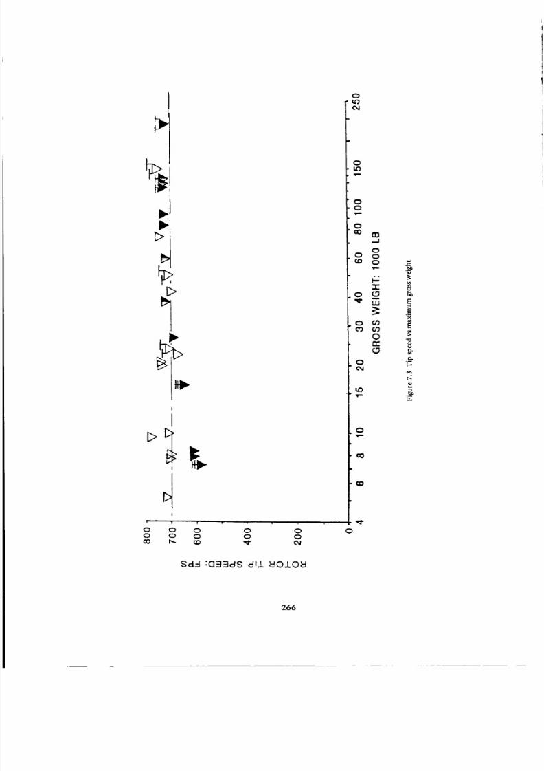
8/3/2019 Stepi Soviet 1
http://slidepdf.com/reader/full/stepi-soviet-1 276/298
E>
O O oo o o00 _,- (D
0 0o o'_" (w
$d6 :GBBd$ dWl _O10_
Ouo04
OuOv,-
O
O
O
m
..J
o
ooO
6z
O 0_cO O9
Oto-
o
04
o
co
o
'_,
0
266

8/3/2019 Stepi Soviet 1
http://slidepdf.com/reader/full/stepi-soviet-1 277/298
I
O
>
I
6 _
I !
I
f
0
00
b b
?|
d _ d
0t_
00
0
00
I
0
b
• • w
d d d d d o
OIIVI::I :IONVACIV l::JO "ON NOVlAI ¢:III IDNIONVA(]V
g
.o
267

8/3/2019 Stepi Soviet 1
http://slidepdf.com/reader/full/stepi-soviet-1 278/298
\\
\.
\
o
ooC_l
oLo
/
'/., .//_
I:::>...";I:::>
v , ,
O O O O O O O O O O O OO O O O O O O O O O O
,t=- _==
.-IScl:ONIOYO7 V31::IV 3.LVTcl ,,I.V7_-II.N37VAINO3
O
O
O
,.d
_ooo
Lu
c_0_coO
o OdL_
'e'*
o
co
o
O..
o
:::so*'
fT.,
268

8/3/2019 Stepi Soviet 1
http://slidepdf.com/reader/full/stepi-soviet-1 279/298
I
0 _ 0 1.0
!
0
0
0o
o
0
L\
T _ F'_.I _'-
i " J
o d d o ci d dI_ IN3101=ld300 1.1173OVI_3AV
' ' 1•-' 0 0 0 0
6 d o 6 c_
<
,...,
8
,q.
f.i.,
269

8/3/2019 Stepi Soviet 1
http://slidepdf.com/reader/full/stepi-soviet-1 280/298
each aircraft was selected whenever possible as a basis for computing the weight empty and zero-range
payload to gross-weight ratios (Figs. 7.7 and 7.8). Values related to normal gross weights are also shown.
From these figures, one can see that weight-wise, the Soviet production helicopters are generally less effi-
cient than their Western counterparts. But, judging from the trends established by the hypothetical
machines, they expect to have their new designs on the optimal boundary of the Western helicopters.
Furthermore, it is apparent that the rather ambitious weight goals represented by the hypothetical heli-
copters have actually been achieved in the Mi-26 helicopter.
7.4 Hovering Aspects
Overall Figure of Merit. It can be seen from Fig. 7.9 that all twin-rotor configurations (i.e., coaxial,
side-by-side, and tandem) exhibit the highest overall figures of merit, generally in excess of the 0.6 level.
Single-rotor helicopters show lower values of the overall figure of merit, with noticeable scatter. As far as
the comparison of Soviet and Western helicopters is concerned, there seems to be no established pattern
of differences.
SHP per Pound of Gross Weight Required in Hover OGE at SL, ISA. Figure 7.10 indicates that the
SHP per pound of gross weight required to hover OGE at SL, ISA increases as the size, with the corre-
sponding disc loading, becomes larger. Older Soviet and Western designs seem to form the lower boundary
of the hovering power required per unit of gross weight, while in more recent designs of both schools,
including the Mi-26; this expenditure of power becomes higher.
Ratio of Maximum OGE, SL Hovering to Maximum Flying Gross Weights. It is interesting to take
a look at the relationships of the maximum OGE at SL, ISA hovering gross weights and maximum flying
gross weights specified by the manufacturers. A glance at Fig. 7.11 would indicate that definite differ-
ences exist between production Soviet and Western helicopters. In the latter case- in contrast to the
Soviet approach - the SL, ISA maximum hovering weight is almost always higher than the permissible
maximum flying weight. For the Soviet hypothetical machines, this ratio is one since, as previously men-
tioned, the maximum flying gross weight used in this presentation was arbitrarily established as that corre-
sponding to hover OGE at SL, ISA, and for the Mi-26, it is close to one (1.007). For the Mi-24-D at its
normal gross weight, it would probably be quite high; amounting to about 1.24.
7.5 Forward Flight Aspects
SHPIWg r = f(V). A single graph showing this relationship for all of the compared helicopters would
be too crowded. Consequently, the reader is referred back to the SHP/Wgr = f(V) plots for each of the four
considered gross-weight classes; i.e, Figs. 3.19, 4.18, 5.18, and 6.14.
270

8/3/2019 Stepi Soviet 1
http://slidepdf.com/reader/full/stepi-soviet-1 281/298
i
Ir
l
o"II • • • _ .
d o o c_
1HOI3M 880_O/lldlA13 IHOI3M
0
0
8
E
,,=
t.,,
.._
271

8/3/2019 Stepi Soviet 1
http://slidepdf.com/reader/full/stepi-soviet-1 282/298
zoo-J
rn
o_
/
/
i
/
,//
"I-
Z_o_0Z_
O0
.jO.
_N
J
/ /
a.OOco
i' ' , ,
c_ 6 6 o 6 o
IHE)I3M SSOI::IE)I(]VO7,kVd 3ONVEI-OI=I3Z
O
OO04
O
OO
O
o=,
o
-rO
.09
o or
O
cO
e_
O
/=
O
o
O
r,_
,,r.o.
gO
L_
272

8/3/2019 Stepi Soviet 1
http://slidepdf.com/reader/full/stepi-soviet-1 283/298
I
1.0
00c_
0Lo
00
0
o
0
0¢,_
0c_
It)
0
¢0
¢0 cO I.o _. ¢,_
d d o d o
_3AOFt NI 11_31_1 _-IO 3WI7E)I_-I 77Y_3AO
,-I
000
o
O
0 o
273

8/3/2019 Stepi Soviet 1
http://slidepdf.com/reader/full/stepi-soviet-1 284/298
I.
dH/8-t ,OhlIC]V07 _3MOd
I ! i , : ,
CO
J
0
iq
0-r
> _
_--->._0 0Z O_
0
00
0
00q,-
0
0 en,..,,.I
000
0
or,,
O
p
0
871dH :±H_I:IM 880k:RD -.10 ONl_Od _:ld dbl8
<
0
o
o
r_
0
.._
274

8/3/2019 Stepi Soviet 1
http://slidepdf.com/reader/full/stepi-soviet-1 285/298
0
[
E>
>
|
i
I
_" 0 O_ aO
i t,,,o!CO ._Z
< 0n- Z
LUI, o.Z I,..,
Z
rr £.0
--
co :_"1-.
I.o °
i
0Lt)c_
0Oc_
0
oo
o
o
0
cO
0c_
0
cO
tD
•- c_ c5 o cJ
(J.HOI3M 8801=I0)/(78 '=!00 :MD _)NI,_I3AOH)
oo
¢.:,'l,-
W
O
¢3
O
o
0
o_
0
o
./
275

8/3/2019 Stepi Soviet 1
http://slidepdf.com/reader/full/stepi-soviet-1 286/298
Looking at rotary-wing aircraft having gross weights of up to 12,000 pounds (Fig. 3.19) and those
weighing 12,000 to 30,000 pounds (Fig. 4.18), one can see that in the low-speed range, Soviet helicopters
of both classes exhibit lower power requirements than their Western counterparts. It should also be noted
that with the exception of the S-76, which slightly exceeds the (Wgr/D e) = 5 value, the gross-weight to the
equivalent drag ratios of all the other helicopters are disappointingly.low.
In the higher gross-weight classes, the following should be noted: in the 30,000 to lO0,O00-pound
gross-weight class (Fig. 5.18), the Mi-6 appears to exhibit a higher (Wgr/D e) than the compared Western
helicopters, as well as relatively low power requirements throughout the whole range of flight speeds. The
Soviet designers expected to improve the high-speed power requirements over those of the Mi-6, as exem-
plified by the hypothetical 15 and 25-ton helicopters.
The same expectation of improved aerodynamic cleanness is also visible for Soviet hypothetical
helicopters having gross weights over 100,000 pounds; especially, for the Hypo 52-SR helicopter (Fig.
6.14). However, on the basis of the information presendy available, it appears from the SHP/Wg r = f(V)
curve of the Mi-26 that the Soviet designers were not as successful in achieving aerodynamic cleanness
as they were in reaching their structural weight and hovering performance goals.
Optimal Gross-Weight to Equivalent Drag Ratios. The maximum (Wgr/D o) values are summarized
once more in Fig. 7.12. Looking at the design parameters appearing in the formula included with this
figure, one should realize that minimization of the w/wfp ratio would have the greatest effect as far as
betterment of maximum weight to the equivalent drag ratio is concerned. But going too far down with
respect to the disc loading is not very practical because of the weight empty and overall aircraft dimen-
sional aspects. Greatly improved aerodynamic cleanness of design- as represented by the high equivalent
flat-plate area loadings- seems to be the most profitable way of improving the (Wgr/Do)rnax ratio.
Apparently, the Soviet designers intended to follow that line in the past, and probably will continue to try
in the future.
Fast Cruise. It can be seen from Fig. 7.13 that fast cruise is usually performed at about 140 kn for
most Western helicopters, as well as for the large production and hypothetical Soviet helicopters. For the
Mi-26, fast cruise is given as 255 km/h; i.e., 137.6 kn. Small Soviet helicopters, especially the coaxial
configurations, appear to have fast cruise speeds much lower than their Western counterparts.
Ideal Absolute Productivity. Assuming the fast cruise values as shown in Fig. 7.13, the ideal absolute
productivity was computed for payloads corresponding to the 100 n.mi range (Fig. 7.14). Here, it can be
seen that the ideal absolute productivity of production Soviet helicopters remains below that of the corre-
sponding Western machines. The points of hypothetical helicopters are on the Western-trend line, while the
Mi-26 is dose to that line.
276

8/3/2019 Stepi Soviet 1
http://slidepdf.com/reader/full/stepi-soviet-1 287/298
277

8/3/2019 Stepi Soviet 1
http://slidepdf.com/reader/full/stepi-soviet-1 288/298
o
0
0
00
0
0I.o
00
r,:
0
0 0 0 0 0 0 0
N)i :1H91"1-1:10 O:l:ld8
278

8/3/2019 Stepi Soviet 1
http://slidepdf.com/reader/full/stepi-soviet-1 289/298
• \
\
_a. i a • | • i •
O0
0
0
00
01,0
00
000
!
ILl
0rr
0 _
It)
0
Q_
_l! I J I' l I _1 I J_l''' I I I # i • ql_
0 0
I:IHI!_'N - l_l'l :,k.J.IAl.l.OIQCOl=Id
o
_=
279
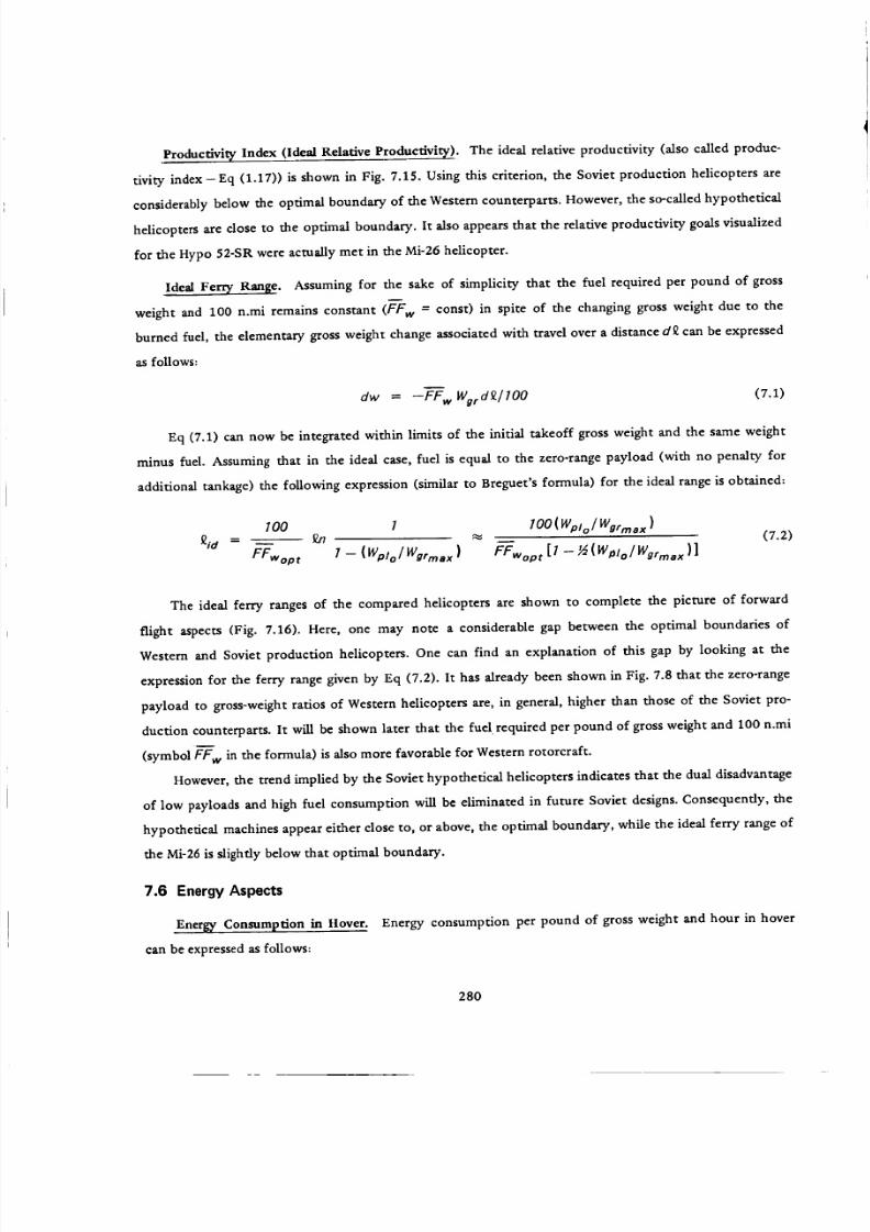
8/3/2019 Stepi Soviet 1
http://slidepdf.com/reader/full/stepi-soviet-1 290/298
Productivity" Index (Ideal Relative Productivit_¢). The ideal relative productivity (also called produc-
tivity index- Eq (1.17)) is shown in Fig. 7.15. Using this criterion, the Soviet production helicopters are
considerably below the optimal boundary of the Western counterparts. However, the so-called hypothetical
helicopters are close to the optimal boundary. It also appears that the relative productivity goals visualized
for the Hypo 52-SR were actually met in the Mi-26 helicopter.
Ideal Ferry Range. Assuming for the sake of simplicity that the fuel required per pound of gross
weight and 100 n.mi remains constant (FF w = const) in spite of the changing gross weight due to the
burned fuel, the elementary gross weight change associated with travel over a distance d_ can be expressed
as follows:
dw = --ff w WgrdQ./ lO0 (7.1)
Eq (7.1) can now be integrated within limits of the initial takeoff gross weight and the same weight
minus fuel. Assuming that in the ideal case, fuel is equal to the zero-range payload (with no penalty for
additional tankage) the following expression (similar to Breguet's formula) for the ideal range is obtained:
7 1oo(w.j°/ Wgr, a,,_id = _ _J7 _" __ (7.2)
FFwopr I -- (Wp/o/Wgrma x ) FFwopr[l - ½(W_to/Wgrrnax)]
I00
The ideal ferry ranges of the compared helicopters are shown to complete the picture of forward
flight aspects (Fig. 7.16). Here, one may note a considerable gap between the optimal boundaries of
Western and Soviet production helicopters. One can find an explanation of this gap by looking at the
expression for the ferry range given by Eq (7.2). It has already been shown in Fig. 7.8 that the zero-range
payload to gross-weight ratios of Western helicopters are, in general, higher than those of the Soviet pro-
duction counterparts. It will be shown later that the fuel required per pound of gross weight and 100 n.mi
(symbol FFw in the formula) is also more favorable for Western rotorcraft.
However, the trend implied by the Soviet hypothetical helicopters indicates that the dual disadvantage
of low payloads and high fuel consumption will be eliminated in future Soviet designs. Consequendy, the
hypothetical machines appear either close to, or above, the optimal boundary, while the ideal ferry range of
the Mi-26 is slightly below that optimal boundary.
7.6 Energy Aspects
,Energ_¢,Consumption in tIover. Energy consumption per pound of gross weight and hour in hover
can be expressed as follows:
280

8/3/2019 Stepi Soviet 1
http://slidepdf.com/reader/full/stepi-soviet-1 291/298
h,
!
/
"C,
.d
,/
/
/
,/
/
t
./
\/
o/
-//
6 " 0
o
c'_
oo
o&(}
0er
0
6 6 6 6 6 6 6 6 o
B'I-blH/!IAI'N-IB'I :X3ONI ,L.LIAI.LC)FIOOI=Id
l:l
C,0
I,(
"0
o
t_
[.t..,
281

8/3/2019 Stepi Soviet 1
http://slidepdf.com/reader/full/stepi-soviet-1 292/298
D,
Ct;n-
UJ
n-Q.
Z--
m
,1 n UJ
_J
_>
rrILlI-
o
.J
"l-
Z _
00
.,jeL
0
00
0
00
0 m
00
0 0
U,I
0 m
O
0
"!I_'N O00L :39NV_I A_I_3.,-I 7V301
282

8/3/2019 Stepi Soviet 1
http://slidepdf.com/reader/full/stepi-soviet-1 293/298
-_-ffw h $fc _= (7.3)550 FMoa
and fuel required per pound of payload and hour would be:
sfcwx/r_p 1
FFpl h = (7.4)
550 Fgoa (Wplol Wer )
Looking at Eq (4.3), one would realize that factors contributing to the betterment of fuel required
per pound of gross weight and hour are: (1) low sfc of the engines; (2) low disc loading-although this may
be in conflict with other requirements; and (3) high overall figure of merit. In the case of minimizing fuel
per pound of payload and hour, as shown in Eq (7.4), a new factor appears under the form of high payload
to gross-weight ratio.
Figure 7.17 clearly indicates that while the band of fuel required per pound of gross weight and hour
is relatively narrow for all the considered helicopters, this fuel consumption when referred to pound of
payload becomes highly scattered. Here, advanced Western and Soviet hypothetical helicopters gravitate
toward the lower boundary of this band, while Soviet production helicopters are grouped toward the
upper limit. Spotting the Mi-26 point in this figure, one would see that this new transport shows hourly
fuel consumption per pound of gross weight and payload very close to those of the Hypo 52-SR. It should
also be noted that the FFp/h value of the Mi-26 is close to the optimal boundary of energy utilization per
pound of payload in hover.
Energy Consumption in Cruise. Energy consumption referred to, say, 100 n.mi and pound of gross
weight for all types of powered vehicles is as follows:
FF---w f = (sfc)v (7.5)
3.25 (Wer/ O e )v
where (sfCJv and (Wgr/D e )v respectively, mean engine specific fuel consumption, and gross weight to the
equivalent drag ratio at speed of flight V.
When the reference base is changed to pound of payload and 100 n.mi, the corresponding fuel con-
sumption equation for cargo vehicles becomes:
(sfc )v (7.6)
FFp/f = 3.25(Wgr/Oe)v(Wp//Wvr )
A glance at the above expression indicates that the requirement for favorable energy consumption is
governed by a low sfc, high gross weight to the equivalent drag ratio, and a payload to gross-weight ratio
as high as possible.
283

8/3/2019 Stepi Soviet 1
http://slidepdf.com/reader/full/stepi-soviet-1 294/298
d d d
_IH-87187 :'_H "_
\
0 Lo 0 LO
d d d o
0(7ci) ONV MO __-I0 "87 i:::13d "031::I 73CI_-I
0
284

8/3/2019 Stepi Soviet 1
http://slidepdf.com/reader/full/stepi-soviet-1 295/298
Optimal fuel requirements per 100 n.mi and pound of gross weight, and zero payload of actual and
hypothetical helicopters can be judged from Fig. 7.18.
In this figure, one may note a picture somewhat similar to that in hover. Here, also, the band of
fuel requirements referred to a unit of gross weight is relatively narrow for all considered helicopters.
When optimal fuel consumption per 100 n.mi is referred to the zero-range payload, the band con-
taining points representing actual helicopters becomes somewhat broader, but for the Western helicopters,
still indicates a definite trend of this quaaatity, decreasing with the increasing size of the rotorcraft.
Some of the Soviet production helicopters appear within, and some above those boundaries, while
the points representing the hypothetical concepts are located at the bottom of the Western trend. Spotting
the Mi-26 helicopter on those graphs, one would see that in both aspects of fuel consumption in cruise,
the chaxacteristics of the actual machine are quite close to those postulated for the hypothetical concepts.
285
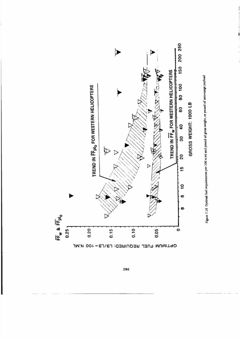
8/3/2019 Stepi Soviet 1
http://slidepdf.com/reader/full/stepi-soviet-1 296/298
t,,.
oll
d
\
• • i , - • w • • • , , • • i
0 Lt) 0 tD
c_ 6 6
0
_I&I'N 001.-87187 :0=II=II170=I_ 7=117-I IAlrll/111dO
0
o
0
0
I:I
0
_.
0
0
©
286

8/3/2019 Stepi Soviet 1
http://slidepdf.com/reader/full/stepi-soviet-1 297/298
REFERENCES
1. Tishchenko,.N.,A.V.Nekrasov,ndA.S.Radin.iertolety, vybor parametrov pri proektirovaniy:
Helicopters, Selection of Design Parameters. Mashinostroyeniye Press, Moscow, 1976.
2. jane's Yearbooks. Jane's Ail the World's Aircraft. London, 1980.
3. Helicopter Financial Services, Inc. Helicopter Blue Book. 1979.
4-. Stepniewski, W.Z. Rotary-Wing Aerodynamics. Vol. 1, NASA CR 3082. 1979.
5. Harris, F.D.; J. D. Kocurek, T.T. McLarty; and T.J. Trept, Jr. Helicopter Performance Methodology
at Bell Helicopter Textron. 35rh National AHS Forum, Paper 79-2. May 1979.
6. Dominick, F., and E.E. Nelson. Engineering Flight Tests, YUH-1H Helicopter, Phase D. USAASTA
Project No. 66-04. Nov. 1970.
7. Keys, C.N. Rotary-WingAerodynamics. Vol. II, NASA CR 3083. 1979.
8. Kocurek, J.D.; L.F. Berkowitz; and F.D. Harris. Hover Performance Methodology at Bell Helicopter
Textron. 36th National AHS Forum Paper 80-3. May 1980.
9. Green, D. Aerospatiale's Remarkable SA-365NDaupbin 2. Rotor and Wing, Int., pp. 54-59, Feb. 1980.
10. Anon. PZL Kania--Kite. Pezetel. Swidnik, Poland.
11. Anon. CH-3E. AGF, Vol. 2, Addn. 50. Sept. 1971.
12. Nagata, J.I., et al. Government Comparative Tests, Util ity TacticaI Transport Aircraft System (UTTAS)
Sikorsky YUH-60A Helicopter. U.S. Army Aviation Engineering Flight Activity, Edwards Airforce
Base, Ca. 9352L Nov. 1976.
13. Anon. CH-53D Standard Aircraft Characteristics, pp. 235-239. N_val Air Systems Command, Navy
Dept. Sept. 1971.
287

8/3/2019 Stepi Soviet 1
http://slidepdf.com/reader/full/stepi-soviet-1 298/298