steinle filter press pump series · steinle filter press pump series edition 2019 rev 1 original...
TRANSCRIPT

Steinle Filter Press Pump Series
edition 2019 rev 1
Original Instruction
Read this instruction manual carefully,
before you install and operate the pump
Pump models:
FP/FH 25
FP/FH 40
FP/FH 50
FP/FH 80
CONTENTS
Steinle Filter Press Pump Series 2
0. GENERAL ......................................................................................................................................... 6
0.1. Introduction................................................................................................................................ 6
0.2. Warning symbols ....................................................................................................................... 6
0.3. Qualification and training of personnel ................................................................................... 6
1. INSTALLATION ............................................................................................................................... 7
1.1. Operation principle .................................................................................................................... 7
1.2. Receiving inspection .................................................................................................................. 8
1.3. Lifting and transportation ......................................................................................................... 8
1.4. Storage ........................................................................................................................................ 9
1.5. Foundation ............................................................................................................................... 10
1.6. Suction and discharge piping ................................................................................................. 10
1.6.1. Connection of suction pipe ............................................................................................. 10
1.6.2. Connection of discharge pipe ......................................................................................... 10
1.7. Health and safety ..................................................................................................................... 10
1.7.1. Protection ......................................................................................................................... 10
1.7.2. Air pressure ....................................................................................................................... 11
1.7.3. Noise level ........................................................................................................................ 11
1.7.4. Temperature hazards ....................................................................................................... 11
1.8. Air connection .......................................................................................................................... 11
1.8.1. Air treatment system ....................................................................................................... 11
1.8.2. Air quality classes ............................................................................................................. 12
1.9. Installation example ................................................................................................................ 13
1.10. Recommended installations ................................................................................................ 13
1.10.1. Flooded ............................................................................................................................. 13
1.10.2. Self-priming ...................................................................................................................... 13
1.11. Electric Connection .............................................................................................................. 13
1.11.1. 24 V DC (Standard) .............................................................................................................. 14
1.11.2. 230 V AC................................................................................................................................ 14
1.11.3. Connection diagram ............................................................................................................ 14
2. OPERATION .................................................................................................................................. 15
2.1. Before starting the pump ........................................................................................................ 15
2.2. Starting and operation ............................................................................................................ 15
2.2.1. Dry running ...................................................................................................................... 15
2.2.2. Optimization of the pump lifetime ................................................................................ 15
2.3. Pump stopping ......................................................................................................................... 16
CONTENTS
Steinle Filter Press Pump Series 3
2.4. Residual risks ............................................................................................................................ 16
2.5. Disposal after expiration of the expected lifetime ............................................................... 16
2.6. Waste of electrical and electronic equipment (WEEE) directive .......................................... 16
2.7. Actions in emergency .............................................................................................................. 16
3. MAINTENANCE ............................................................................................................................ 17
3.1. When the pump is new or reassembled ................................................................................. 17
3.1.1. Performance test .............................................................................................................. 17
3.2. Routine inspection ................................................................................................................... 17
3.3. Complete inspection ................................................................................................................ 17
3.4. Diaphragm monitoring ............................................................................................................ 17
3.5. Location of faults ..................................................................................................................... 18
3.6. FP/FH 25 – Disassembly of the pump .................................................................................... 19
3.6.1. Before the disassembly procedure ................................................................................. 19
3.6.2. Disassembly procedure .................................................................................................... 19
3.6.3. Test run ............................................................................................................................. 23
3.7. FP/FH 40-80 – Disassembly of the pump ............................................................................... 24
3.7.1. Before the disassembly procedure ................................................................................. 24
3.7.2. Disassembly procedure .................................................................................................... 24
3.8. FP/FH – assembly of the pump ............................................................................................... 28
3.9. Changing the parts............................................................................................................... 28
3.9.1. Changing seals .................................................................................................................. 28
3.9.2. Changing the piston and the cylinder ............................................................................ 29
3.9.3. Changing the hose diaphragms ...................................................................................... 29
3.9.3.1. Suction Side .................................................................................................................. 29
3.9.3.2. Discharge Side .............................................................................................................. 29
3.10. Filling of Hydraulic Liquid ............................................................................................... 29
3.10.1. Pump is flooded from the suction side .......................................................................... 29
3.10.2. Pump is not flooded ........................................................................................................ 30
3.10.3. Changing stroke sensors ................................................................................................. 30
3.10.4. Test run ............................................................................................................................. 30
4. SPARE PARTS ................................................................................................................................ 31
4.1. FP-FH 25 – Spare parts drawings ............................................................................................ 31
4.2. FP-FH 25 – Spare parts list ..................................................................................................... 34
4.3. FP-FH 40 – Spare parts drawing ............................................................................................. 36
4.4. FP-FH 40 – Spare parts list ...................................................................................................... 39
4.5. FP-FH 50/80 – Spare parts drawing ........................................................................................ 42
CONTENTS
Steinle Filter Press Pump Series 4
4.6. FP-FH 50/80 – Spare parts list ................................................................................................ 44
4.7. Stocking recommendation ...................................................................................................... 48
4.8. How to order parts................................................................................................................... 49
4.9. Pump code ................................................................................................................................ 50
5. DATA ............................................................................................................................................. 51
5.1. Capacity curves......................................................................................................................... 51
5.2. Capacity changes ...................................................................................................................... 52
5.3. Dimensions ............................................................................................................................... 52
5.4. Technical data .......................................................................................................................... 54
5.5. Tightening torques .................................................................................................................. 55
5.6. Permitted manifold loads ........................................................................................................ 56
6. WARRANTY .................................................................................................................................. 57
6.1. Warranty form .......................................................................................................................... 57
6.2. Returning parts ........................................................................................................................ 58
6.3. Warranty ................................................................................................................................... 58
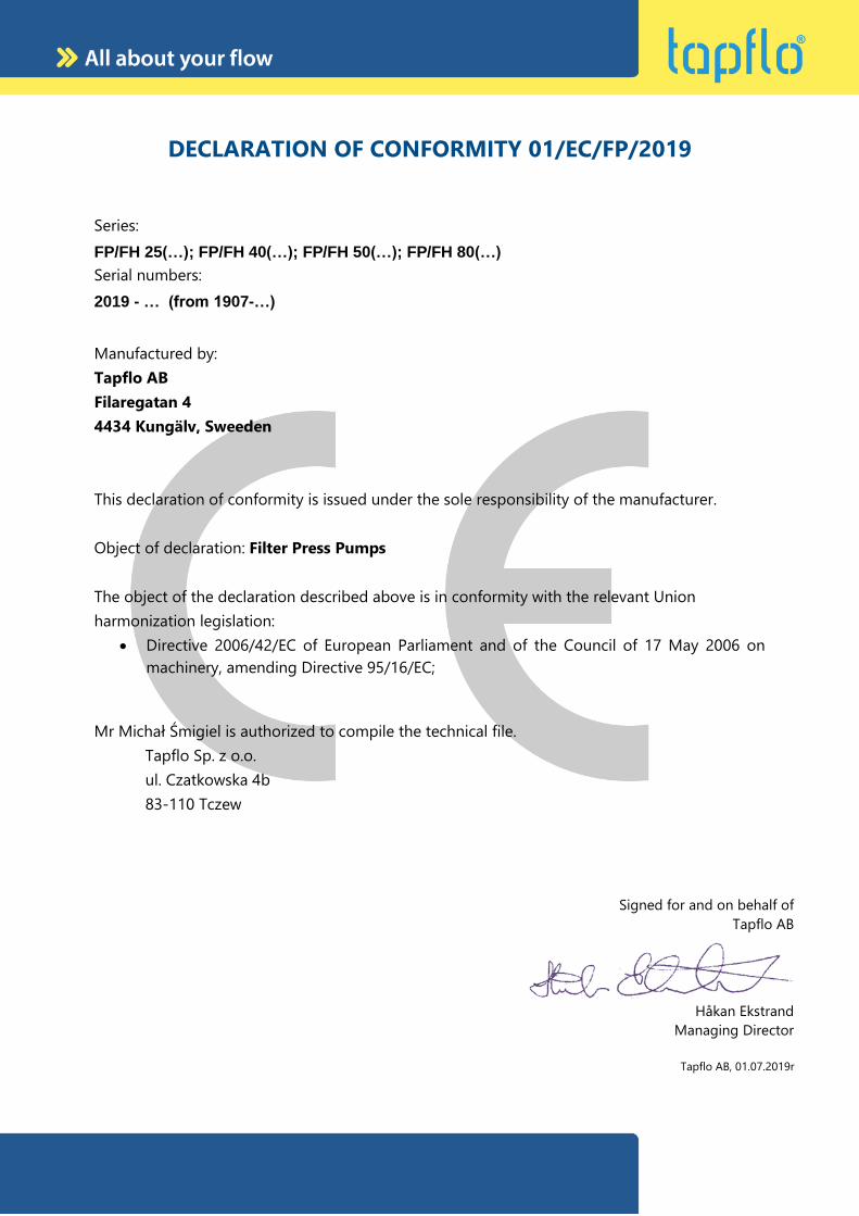
DECLARATION OF CONFORMITY 01/EC/FP/2019
Series:
FP/FH 25(…); FP/FH 40(…); FP/FH 50(…); FP/FH 80(…)
Serial numbers:
2019 - … (from 1907-…)
Manufactured by:
Tapflo AB
Filaregatan 4
4434 Kungälv, Sweeden
This declaration of conformity is issued under the sole responsibility of the manufacturer.
Object of declaration: Filter Press Pumps
The object of the declaration described above is in conformity with the relevant Union
harmonization legislation:
• Directive 2006/42/EC of European Parliament and of the Council of 17 May 2006 on
machinery, amending Directive 95/16/EC;
Mr Michał Śmigiel is authorized to compile the technical file.
Tapflo Sp. z o.o.
ul. Czatkowska 4b
83-110 Tczew
Signed for and on behalf of
Tapflo AB
Håkan Ekstrand
Managing Director
Tapflo AB, 01.07.2019r
0. GENERAL
Steinle Filter Press Pump Series 6
0. GENERAL
0.1. Introduction
The FP/FH Air Operated Filter Press Pump range is a complete series of pumps for industrial
applications. The pumps are designed to be safe, simple and easy to use and maintain. The
construction is seal-less and without rotating parts. The pumps are suitable for a variety of
duties in filter press installations.
With proper attention to maintenance, Tapflo Pumps will give efficient and trouble free
operation. This instruction manual will familiarise operators with detailed information about
installing, operating and maintaining of the pump.
The design and function allows the user a straightforward pressing of slurries.
When installing, operating and maintaining of the pump unit you must strictly follow the
IOM manual. Otherwise injury or life hazard may occur.
0.2. Warning symbols
The following warning symbols are present in this instruction manual. This is what they say:
This symbol stands next to all safety instructions in this instruction manual where
danger to life and limb may occur. Observe these instructions and proceed with
utmost caution in these situations. Inform also other users of all safety
instructions. In addition to the instructions in this instruction manual, the general
safety and accident prevention regulations must be observed.
This signal stands at points in this instruction manual of particular importance
for compliance with regulations and directives, for correct work flow and for the
prevention of damage to and destruction of the complete dampener or its
subassemblies.
0.3. Qualification and training of personnel
The personnel in charge of installation, operation and maintenance of the pumps we
produce must be qualified to carry out the operations described in this manual. Tapflo shall
not be held responsible for the training level of personnel and for the fact that they are not
fully aware of the contents of this manual. In case any instructions in this manual are unclear
or any information is lacking, please contact Tapflo before handling the pump.
1. INSTALLATION
Steinle Filter Press Pump Series 7
1. INSTALLATION
1.1. Operation principle
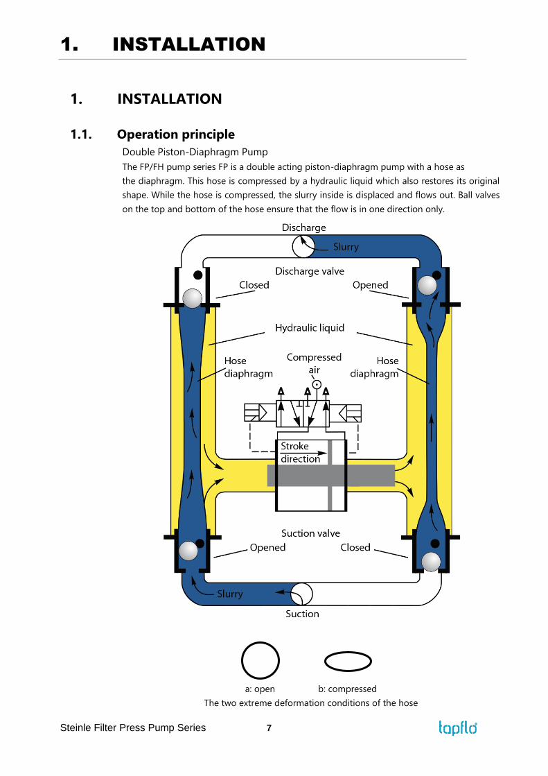
Double Piston-Diaphragm Pump
The FP/FH pump series FP is a double acting piston-diaphragm pump with a hose as
the diaphragm. This hose is compressed by a hydraulic liquid which also restores its original
shape. While the hose is compressed, the slurry inside is displaced and flows out. Ball valves
on the top and bottom of the hose ensure that the flow is in one direction only.
a: open b: compressed
The two extreme deformation conditions of the hose
1. INSTALLATION
Steinle Filter Press Pump Series 8
The hose only has to separate the hydraulic liquid from the slurry and is pressure-neutral. The
pressure inside and outside the hose is always the same. This is why the diaphragm has an
extremely long service life besides the fact that it is never compressed totally. It only flexes in
the elastic range of the material.
Pneumatic Drive
Compressed air is moving the pneumatic piston which is attached to the hydraulic piston. The
hydraulic piston is moving the hydraulic liquid which is acting on the diaphragm hose. Pressure
transmission ratio is created by the difference in surface area size between pneumatic and
hydraulic pistons. The end-point in the movement of the air piston is registered by two
electronic sensors without any mechanical contact. The signal of these switches controls an
electric 5/2 solenoid valve which leads the air to the opposite side of the piston.
Self-Regulating
The pneumatic drive system of the pump results in a continuous balance between the flow
rate of the pump and the quantity of slurry required by the filter press. The pump system thus
regulates itself. Even if a valve on the discharge side is closed, the pump simply stops and has
no energy consumption. When the valve is opened, the pump starts to operate again. Thanks
to this property, no additional pump control units, such as pressure switches, are required.
Double Security
Even if the hose is damaged, the pump will continue to work as a simple piston pump. This
means that it ensures double security. It can be repaired some days later. Damage to the hose
can be detected by an optional sensor unit. The hydraulic liquid is environmentally friendly
hydraulic and lubricating oils based on synthetic ester.
1.2. Receiving inspection
Although precaution is taken by us when packing and shipping, we urge you to carefully check
the shipment on receipt. Make sure that all parts and accessories listed on the packing list are
accounted for. Immediately report any damage or shortage to the transport company and to
us.
1.3. Lifting and transportation
Before handling the pump check the weight of the pump (see 5.4. Technical data). Refer to
Your local standards on how to handle the pump. If the weight is excessive to transport by
hand it must be lifted using slings and a suitable lifting device e.g. a crane or forklift.
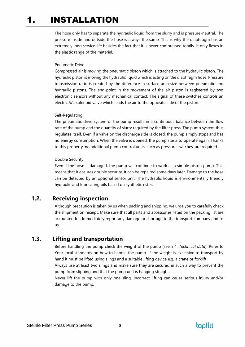
Always use at least two slings and make sure they are secured in such a way to prevent the
pump from slipping and that the pump unit is hanging straight.
Never lift the pump with only one sling. Incorrect lifting can cause serious injury and/or
damage to the pump.
1. INSTALLATION
Steinle Filter Press Pump Series 9
Never lift the pump under pressure.
Be careful that nobody passes under the pump when lifted.
Never try to lift the pump by the hoses attached to the pump.
As an option pumps can be equipped with lifting eyebolts connected with the pump housing.
1.4. Storage
If the equipment is to be stored prior to installation, place it in a clean location. The pump
should be stored in an ambient temperature of 15°C (59°F) to 25°C (77°F) and relative humidity
below 65%. It should not be exposed to any heat source e.g. radiator, sun as this could result
in a negative way on the tightness of the pump. Do not remove the protective covers from the
suction, discharge and air connections which have been fastened to keep pump internals free
of debris. Clean the pump thoroughly before installation.
1. INSTALLATION
Steinle Filter Press Pump Series 10
1.5. Foundation
The pump is furnished with vibration absorbing base frame. The pump will operate properly
without additional shock absorbers. Make sure the foundation is able to absorb vibrations and
fix the base frame with screws to the foundation. It is essential for the operation of the pump
to mount the pump vertical. (see sketch in chapter 1.10 “Recommended installations”).
1.6. Suction and discharge piping
Suction and discharge piping should be fully supported and anchored near to but independent
of the pump. The piping to the pump should be a hose, to prevent undue stress and strain on
the pump connections and the piping.
1.6.1. Connection of suction pipe
Remember that the suction pipe/connection is the most critical point, especially if the pump
is priming. Just a small leakage will dramatically reduce the suction capability of the pump.
When connecting the suction pipe, following is recommended.
1) For satisfactory operation, use reinforced hose (the suction power may otherwise
shrink the hose) or other flexible piping. The internal diameter of the hose should be
the same as on the suction connection (at the bottom of the pump) to have best
suction capability.
2) Make sure that the connection hose - pump is completely tight, otherwise the suction
capability will be reduced.
3) Always use as short suction pipe as possible. Avoid air pockets which can arise with
long piping.
1.6.2. Connection of discharge pipe
For this connection it is only recommended a simple and positive flow connection. Use a hose
or flexible piping (minimum one meter) between the discharge connection and any rigid fixed
piping. Coil the hose at least one turn. All components (hose, pipe, valves etc.) on the discharge
piping must be designed for minimum PN 16 for FP pumps and pumps with PP manifold, PN
25 for FH pumps.
1.7. Health and safety
The pump must be installed according to local and national safety rules.
The pumps are constructed for particular applications. Do not use the pump on
applications different from that for which it was sold without consulting us to ascertain
its suitability.
1.7.1. Protection
In the interest of health and safety it is essential to wear protective clothing and safety goggles
when operating, and/or working in the vicinity of Tapflo pumps.
1. INSTALLATION
Steinle Filter Press Pump Series 11
1.7.2. Air pressure
The maximum air pressure for FP/FH series pumps is 8 bar. Higher air pressure than 8 bar can
damage the pump and may cause injury to personnel in vicinity of the pump. If you intend to
apply a higher air pressure than 8 bar, please consult us.
1.7.3. Noise level
At tests, the noise level from a FP/FH pump has not exceeded 80 dB(A). Under some
circumstances, for example if the pump is operating under high air pressure at low discharge
head, the noise can be inconvenient or hazardous for personnel staying for long periods in
the vicinity of the pump. This hazard can be prevented by:
➢ using suitable ear protection;
➢ lowering the air pressure and/or raising the discharge head;
➢ leading out the outgoing air from the room by connecting a hose to the muffler
connection of the pump;
1.7.4. Temperature hazards
➢ Raised temperature can cause damage on the pump and/or piping and may also be
hazardous for personnel in the vicinity of the pump/piping. Avoid quick temperature
changes and do not exceed the maximum temperature specified when the pump was
ordered. See also general max temperatures based on water in chapter 5. “DATA”.
➢ When the pump is exposed to ambient temperature variations or if there is big difference
between the temperature of the product and the surrounding, the tightening torques of
the housing nuts should be checked periodically as part of preventive maintenance. Please
contact Tapflo for tightening intervals recommendation.
➢ If a hot product is pumped, the pump should not stand still when filled for a longer period
of time. This could cause leakage from the valves and contamination and/or damage of
the air valve.
➢ Below 0°C (32°F) plastic materials become more fragile what can cause accelerated wear
of parts made of these materials. This is a hazard that has to be accepted when pumping
such cold products. Also in such case, when a pump is not operational it should be drained
of all liquid.
➢ Bear in mind that the viscosity of the product changes with temperature. This has to be
taken into consideration when selecting the pump.
1.8. Air connection
Screw the air hose into the air intake of the pump with for example a bayonet coupling. For
best efficiency, use the same hose diameter as the internal diameter of the connection on the
air intake.
1.8.1. Air treatment system
Maximum air pressure is 8 bar. As prevention purpose, a filtration of the air by means of a 5
micron filter or finer is recommended. Recommended air quality according to PN-ISO8573-
1:2010 is particles class 7, water class 4 and oil class 4. Dirt in the air can under unfortunate
circumstances be the cause of a breakdown. The air valve is constructed for oil free air.
1. INSTALLATION
Steinle Filter Press Pump Series 12
Lubrication of the air increases the life time of the pneumatic parts. But when the air once is
lubricated, the lubrication never may be interrupted. For more details please contact your
Tapflo representative.
To facilitate the operation of the pump we recommend an air treatment system connected to
the air supply. These components should be included:
1) Regulator to adjust the air pressure;
2) Manometer to read the actual pressure;
3) Needle valve to adjust the air flow (especially when operating the pump in the lower range
of performance);
4) Filter.
These components are included in Tapflo’s Air treatment system which can be ordered from
us.
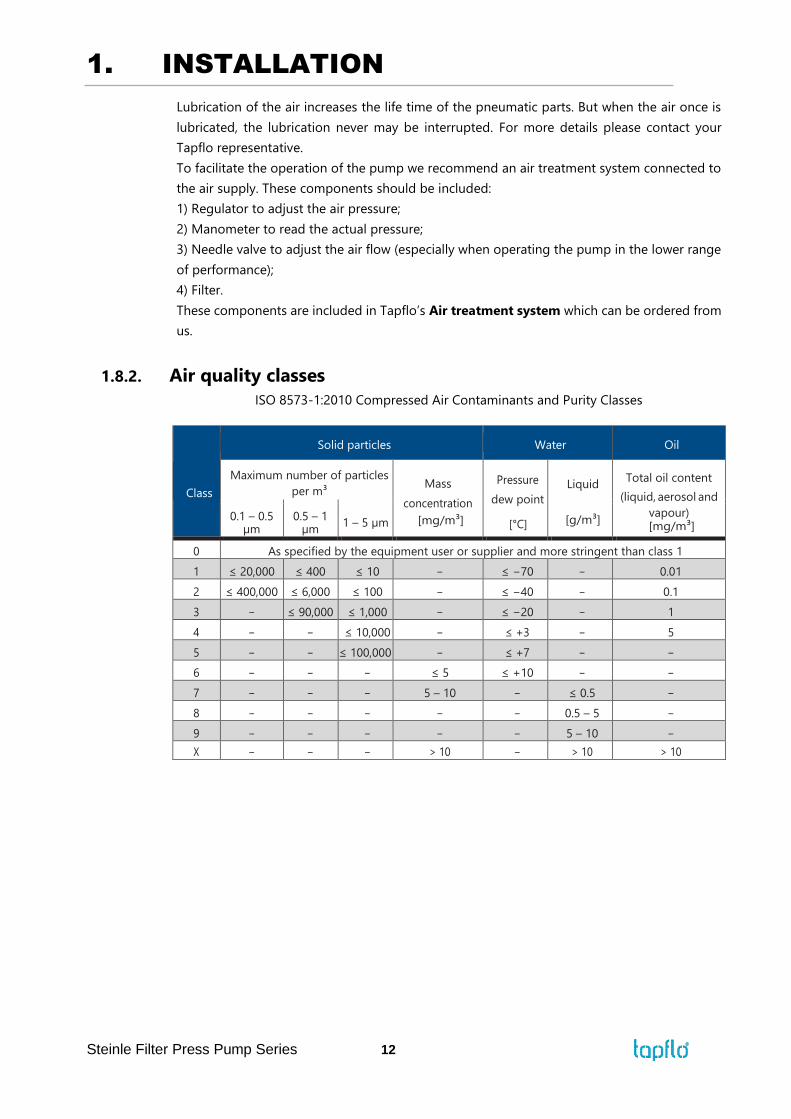
1.8.2. Air quality classes
ISO 8573-1:2010 Compressed Air Contaminants and Purity Classes
Class
Solid particles Water Oil
Maximum number of particles
per m³ Mass
concentration
[mg/m³]
Pressure
dew point
[°C]
Liquid
[g/m³]
Total oil content
(liquid, aerosol and
vapour) [mg/m³]
0.1 – 0.5 µm
0.5 – 1 µm
1 – 5 µm
0 As specified by the equipment user or supplier and more stringent than class 1
1 ≤ 20,000 ≤ 400 ≤ 10 − ≤ −70 − 0.01
2 ≤ 400,000 ≤ 6,000 ≤ 100 − ≤ −40 − 0.1
3 − ≤ 90,000 ≤ 1,000 − ≤ −20 − 1
4 − − ≤ 10,000 − ≤ +3 − 5
5 − − ≤ 100,000 − ≤ +7 − −
6 − − − ≤ 5 ≤ +10 − −
7 − − − 5 – 10 − ≤ 0.5 −
8 − − − − − 0.5 – 5 −
9 − − − − − 5 – 10 −
X − − − > 10 − > 10 > 10
1. INSTALLATION
Steinle Filter Press Pump Series 13
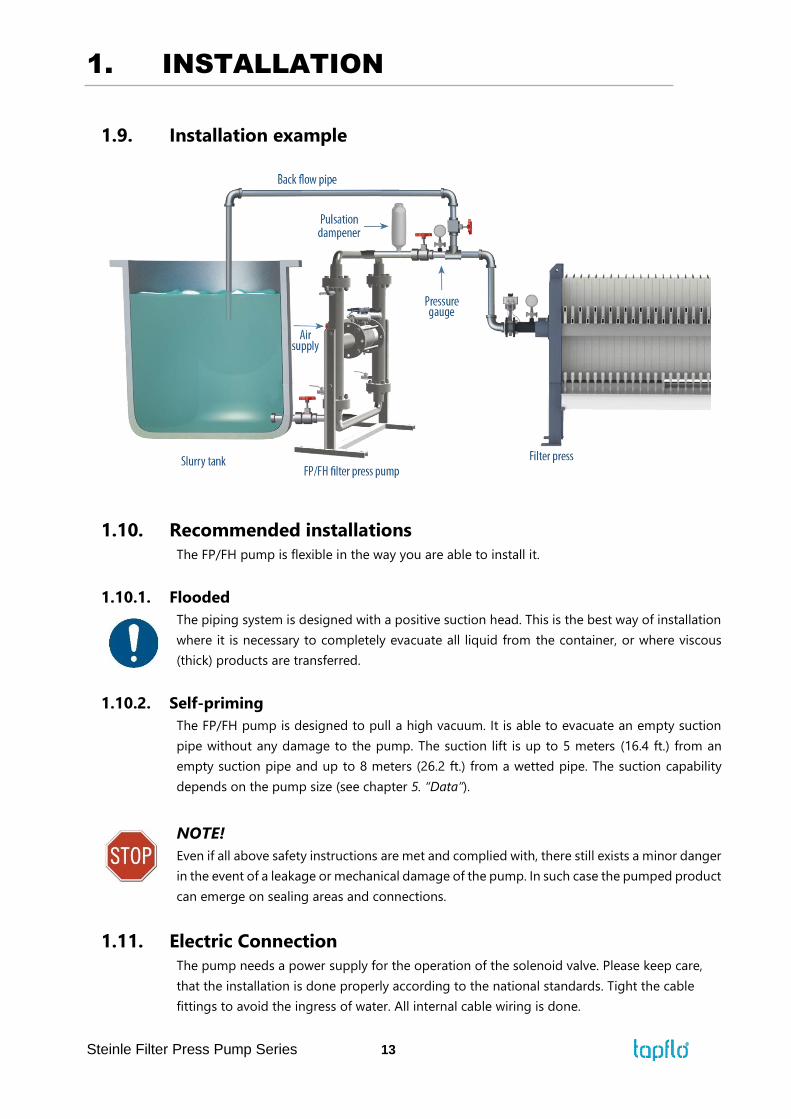
1.9. Installation example
1.10. Recommended installations
The FP/FH pump is flexible in the way you are able to install it.
1.10.1. Flooded
The piping system is designed with a positive suction head. This is the best way of installation
where it is necessary to completely evacuate all liquid from the container, or where viscous
(thick) products are transferred.
1.10.2. Self-priming
The FP/FH pump is designed to pull a high vacuum. It is able to evacuate an empty suction
pipe without any damage to the pump. The suction lift is up to 5 meters (16.4 ft.) from an
empty suction pipe and up to 8 meters (26.2 ft.) from a wetted pipe. The suction capability
depends on the pump size (see chapter 5. “Data”).
NOTE!
Even if all above safety instructions are met and complied with, there still exists a minor danger
in the event of a leakage or mechanical damage of the pump. In such case the pumped product
can emerge on sealing areas and connections.
1.11. Electric Connection
The pump needs a power supply for the operation of the solenoid valve. Please keep care,
that the installation is done properly according to the national standards. Tight the cable
fittings to avoid the ingress of water. All internal cable wiring is done.

1. INSTALLATION
Steinle Filter Press Pump Series 14
1.11.1. 24 V DC (Standard)
The power supply is connected to the clamps inside the control box, marked with + and -.
Keep care for the right poles. The power consumption is 12 W.
1.11.2. 230 V AC
The power supply is connected to the clamps inside the control box, marked with L, N, and
PE (ground connection). Keep care, that the ground connection is installed properly.
1.11.3. Connection diagram
2. OPERATION
Steinle Filter Press Pump Series 15
2. OPERATION
2.1. Before starting the pump
➢ Make sure the pump is installed according to the installation instruction (chapter 1).
➢ Filling of the pump with liquid before start is not necessary. Only at high suction lift it
may help to fill the pump with water on the suction side to increase the suction
capability.
➢ When installation is new or reinstalled, a test run of the pump with water should be
conducted to make sure that the pump operates normally and does not leak.
2.2. Starting and operation
➢ Open the discharge valve.
➢ Pull out the red button on the control box to switch the control power.
➢ Note! Considering the suction capacity when air is still in the suction pipe, it is
recommended to start with low air pressure/flow (slowly) at the beginning. This
is not necessary if the pump is filled with liquid before start.
➢ When the pump has been filled with liquid, the air pressure/flow may be raised in order
to increase the suction capacity of the pump.
➢ FP25: 60 1/min
➢ FP40: 83 1/min
➢ FP50: 58 1/min
➢ FP80: 75 1/min
➢ The performance of the pump can be adjusted through the air supply by using a needle
valve and a pressure regulator. The performance can also be adjusted by normal flow
control on the discharge side of the system.
2.2.1. Dry running
Although the pump is prepared for dry running it is important to have in mind that long
periods of dry run may increases the wear. Also an empty pump should operate at low
speeds – controlled by a needle-valve.
2.2.2. Optimization of the pump lifetime
➢ Running at full frequency (maximum air pressure/flow) continuously will cause
premature wear of the components.
➢ As stated in chapter 1.8.1 Tapflo recommends to use an appropriate air treatment
system in order to extend the pump’s lifetime.
➢ If the air humidity is high, use of a water separator or air dryer is recommended.
Otherwise on the air discharge side due to decompression, icing on the muffler can
appear causing it to shrink and eventually it can shoot out of its socket.
➢ If the ambient air is humid, icing can occur outside of the muffler. In such case it is
recommended to use a longer exhaust of the compressed air (ca. 500 mm / 19,7’’).
2. OPERATION
Steinle Filter Press Pump Series 16
➢ If there is possibility of freezing at the air exhaust, it is good to pre-heat the air before it
reaches the air intake in order to raise the dew point of the air.
NOTE! Make sure that the air temperature does not exceed 50°C (122°F).
2.3. Pump stopping
The pump can be stopped in three ways:
1) Close the discharge valve. The pressure from the system will stop the pump
automatically. This will not do any damage to the pump. The pump restarts easy when
the valve is opened again.
2) By cutting off the air supply.
3) Switch off control panel
2.4. Residual risks
Even with proper application and observance of all points listed in this operating manual,
there is still an estimable and unexpected residual risk when using the pumps. It may leak,
fail due to wear, application-related causes or system-related circumstances.
2.5. Disposal after expiration of the expected lifetime
The metallic components like aluminium, stainless steel and carbon steel can be recycled.
Plastic parts are not recyclable and must be disposed of as residual waste. The pump must
be disposed of properly, according to local regulations. It should be noted that potentially
dangerous fluid residues may remain in the pump and can create a hazard to the operator
or the environment, therefore the pump has to thoroughly cleaned before disposal.
The oil is biodegradable, however, it must be recycled according to national regulations.
2.6. Waste of electrical and electronic equipment (WEEE) directive
Users of electrical and electronic equipment (EEE) with the WEEE
marking per Annex IV of the WEEE Directive must not dispose of end
of life EEE as unsorted municipal waste, but use the collection
framework available to them for the return, recycle, recovery of WEEE
and minimize any potential effects of EEE on the environment and
human health due to the presence of hazardous substances. The WEEE
marking applies only to countries within the European Union (EU) and Norway. Appliances
are labelled in accordance with European Directive 2002/96/EC. Contact your local waste
recovery agency for a designated collection facility in your area.
2.7. Actions in emergency
In case of a leakage of an unknown fluid, respiratory protection should be worn and
contact with the fluid avoided. During firefighting, keep in mind that hydraulic part of
pump is filled with oil and control unit is connected to electricity. In addition, the currently
handled fluid and the corresponding safety data sheet must be taken into account. In the
event of personal injury, the appropriate emergency number or 112 must be chosen.
3. MAINTENANCE
Steinle Filter Press Pump Series 17
3. MAINTENANCE
3.1. When the pump is new or reassembled
If the pump is new or reassembled after maintenance it is important to retighten the
pump manifolds screws (pos. 38) after approximately one week of operation. Make
sure to use the right torque – see chapter 5.5 “Tightening torques”.
3.1.1. Performance test
When installation is new, a test run of the pump should be conducted. Gauge the capacity
at specific air pressure/flow. This information is useful for checking performance in the
future as wear takes place. You will be able to set schedules for maintenance of the pump
and to select spare parts to be kept on stock.
3.2. Routine inspection
Frequent observation of the pump operation is recommended to detect problems. A change
in sound of the running pump can be an indication of wearing parts (see chapter 3.5
"Location of faults" below).
Leaking liquid from the pump and changes of performance may also be detected. Routine
inspections should be conducted frequently.
The installation of pressure gauges in the filling nozzles of the hydraulic allows the
observation of function of the hydraulic. When pressure gauges with a range of -1 to +15bar
are used, the suction lift also can be inspected.
3.3. Complete inspection
The intervals for a complete inspection depend upon the operation conditions of the pump.
The characteristics of the liquid, temperature, materials used in the pump and running time
decide how often a complete inspection is necessary.
If a problem has occurred, or if the pump is in need of a complete inspection, refer to
chapters 3.5 "Location of faults" and 3.6, 3.7 "Dismantling of the pump". You are of course
warmly welcome to consult us for further help.
Parts that are subject to wear should be kept in stock, see our recommendations in chapter
4.7 “Stocking recommendation”.
3.4. Diaphragm monitoring
A break of the diaphragm causes a flow of slurry into the hydraulic liquid and also an
increase of the conductivity of the hydraulic liquid. This can be controlled by our
diaphragm control system, which is available as an accessory.

3. MAINTENANCE
Steinle Filter Press Pump Series 18
3.5. Location of faults
PROBLEM POSSIBLE FAULT POSSIBLE SOLUTION
The pump does not
run
No control power Switch red button at the control box, check
polarity
Too much hydraulic liquid (one
pressure gauge at housing indicates
pressure)
Drain hydraulic liquid or adjust the
diaphragm
The air pressure is to low Increase air pressure via a filter-regulator
The air connection is blocked Check / clean air supply connection
The suction is bad
Muffler is blocked Check / clean / replace muffler
Suction connection is not tight Tighten the suction line
Suction connection is blocked Clean suction line
Valve balls are blocked or damaged Check dimensions and shape of valve balls
Valve seats are worn Check dimensions and shape of valve seats
Pump starts with high pressure Start the pump slowly (see chapter 2.2)
Air in suction / discharge line Vent suction / discharge line
Dry suction against discharge
pressure
Wet the pump / start without discharge
pressure
The pump runs
irregular
Valve balls are blocked Check dimensions and shape of valve balls
Diaphragm breakdown Replace diaphragm
Check dimensions and shape of valve seats
Valve seats are worn Check dimensions and shape of valve seats
Icing on the muffler Improve air quality (see chapters 1.7.1 and
2.2.2)
Bad flow/pressure
Pressure fall in air supply Increase air pressure via a filter-regulator
Pressure losses on suction side Check/change installation on suction side
Air supply / air valve leaking Check / repair / replace air supply / air valve
Suction or air connection blocked Check / clean air supply / suction connection
Muffler is blocked Check / clean / replace muffler
Valve ball worn or broken Check dimensions and shape of valve balls
Valve seats are worn Check dimensions and shape of valve seats
Air in liquid Seal suction line; check / refill container
Diaphragm breakdown
Icing on the muffler
Check / replace diaphragms
Improve air quality (see chapters 1.7.1 and
2.2.2)
Air in hydraulic system Remove air
Air in pipe system Remove air
Suction pipe untight Tighten
Pump leaks oil
Piston speed too high Reduce air supply
Cavitation in hydraulic system
Check ball valves
Install larger suction pipe
Install pulsation dampener on
suction side
Seal worn out Install filter in air supply
Change seal
Pump stops
Failure in control system Check control system and
change sensors or solenoid valve
Pressure on discharge too high Increase air pressure
No control power Switch on power
Diaphragm
breakdown Wrong selection of material
Contact us for information on material
selection
3. MAINTENANCE
Steinle Filter Press Pump Series 19
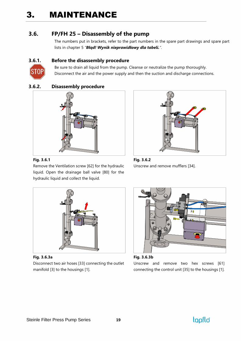
3.6. FP/FH 25 – Disassembly of the pump
The numbers put in brackets, refer to the part numbers in the spare part drawings and spare part
lists in chapter 5 “Błąd! Wynik nieprawidłowy dla tabeli.”.
3.6.1. Before the disassembly procedure
Be sure to drain all liquid from the pump. Cleanse or neutralize the pump thoroughly.
Disconnect the air and the power supply and then the suction and discharge connections.
3.6.2. Disassembly procedure
Fig. 3.6.1
Remove the Ventilation screw [62] for the hydraulic
liquid. Open the drainage ball valve [80] for the
hydraulic liquid and collect the liquid.
Fig. 3.6.2
Unscrew and remove mufflers [34].
Fig. 3.6.3a
Disconnect two air hoses [33] connecting the outlet
manifold [3] to the housings [1].
Fig. 3.6.3b
Unscrew and remove two hex screws [61]
connecting the control unit [35] to the housings [1].
3. MAINTENANCE
Steinle Filter Press Pump Series 20
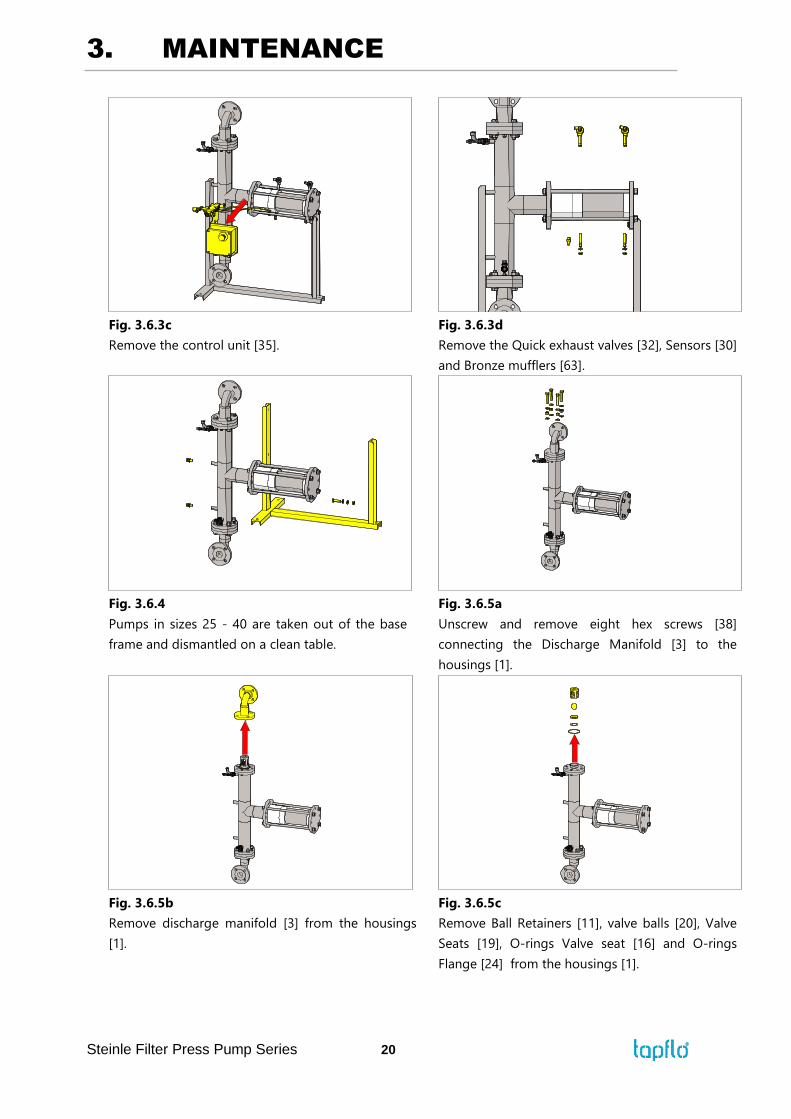
Fig. 3.6.3c
Remove the control unit [35].
Fig. 3.6.3d
Remove the Quick exhaust valves [32], Sensors [30]
and Bronze mufflers [63].
Fig. 3.6.4
Pumps in sizes 25 - 40 are taken out of the base
frame and dismantled on a clean table.
Fig. 3.6.5a
Unscrew and remove eight hex screws [38]
connecting the Discharge Manifold [3] to the
housings [1].
Fig. 3.6.5b
Remove discharge manifold [3] from the housings
[1].
Fig. 3.6.5c
Remove Ball Retainers [11], valve balls [20], Valve
Seats [19], O-rings Valve seat [16] and O-rings
Flange [24] from the housings [1].
3. MAINTENANCE
Steinle Filter Press Pump Series 21
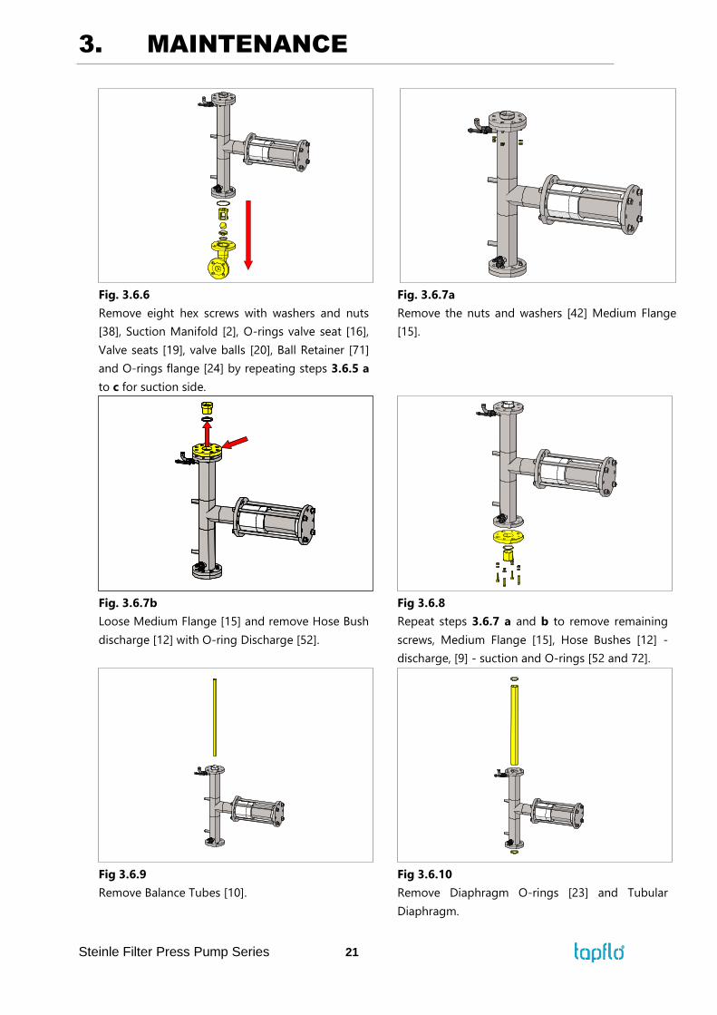
Fig. 3.6.6
Remove eight hex screws with washers and nuts
[38], Suction Manifold [2], O-rings valve seat [16],
Valve seats [19], valve balls [20], Ball Retainer [71]
and O-rings flange [24] by repeating steps 3.6.5 a
to c for suction side.
Fig. 3.6.7a
Remove the nuts and washers [42] Medium Flange
[15].
Fig. 3.6.7b
Loose Medium Flange [15] and remove Hose Bush
discharge [12] with O-ring Discharge [52].
Fig 3.6.8
Repeat steps 3.6.7 a and b to remove remaining
screws, Medium Flange [15], Hose Bushes [12] -
discharge, [9] - suction and O-rings [52 and 72].
Fig 3.6.9
Remove Balance Tubes [10].
Fig 3.6.10
Remove Diaphragm O-rings [23] and Tubular
Diaphragm.
3. MAINTENANCE
Steinle Filter Press Pump Series 22
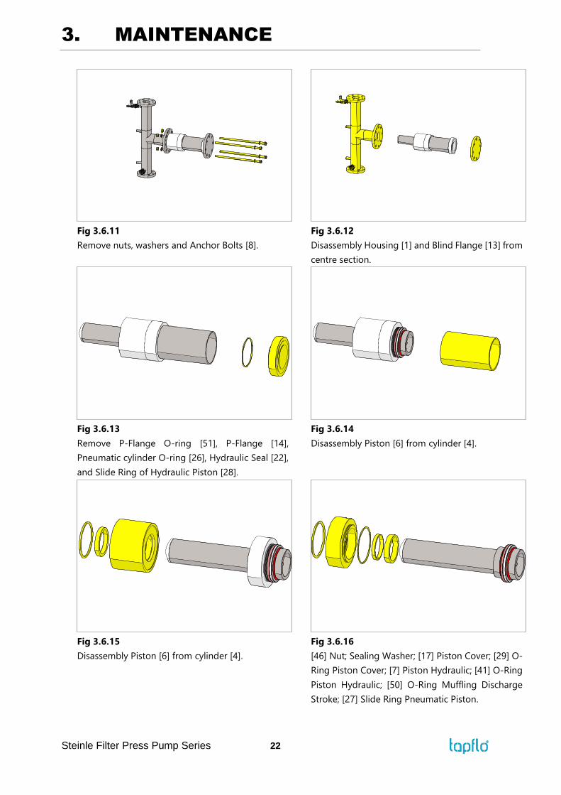
Fig 3.6.11
Remove nuts, washers and Anchor Bolts [8].
Fig 3.6.12
Disassembly Housing [1] and Blind Flange [13] from
centre section.
Fig 3.6.13
Remove P-Flange O-ring [51], P-Flange [14],
Pneumatic cylinder O-ring [26], Hydraulic Seal [22],
and Slide Ring of Hydraulic Piston [28].
Fig 3.6.14
Disassembly Piston [6] from cylinder [4].
Fig 3.6.15
Disassembly Piston [6] from cylinder [4].
Fig 3.6.16
[46] Nut; Sealing Washer; [17] Piston Cover; [29] O-
Ring Piston Cover; [7] Piston Hydraulic; [41] O-Ring
Piston Hydraulic; [50] O-Ring Muffling Discharge
Stroke; [27] Slide Ring Pneumatic Piston.
3. MAINTENANCE
Steinle Filter Press Pump Series 23
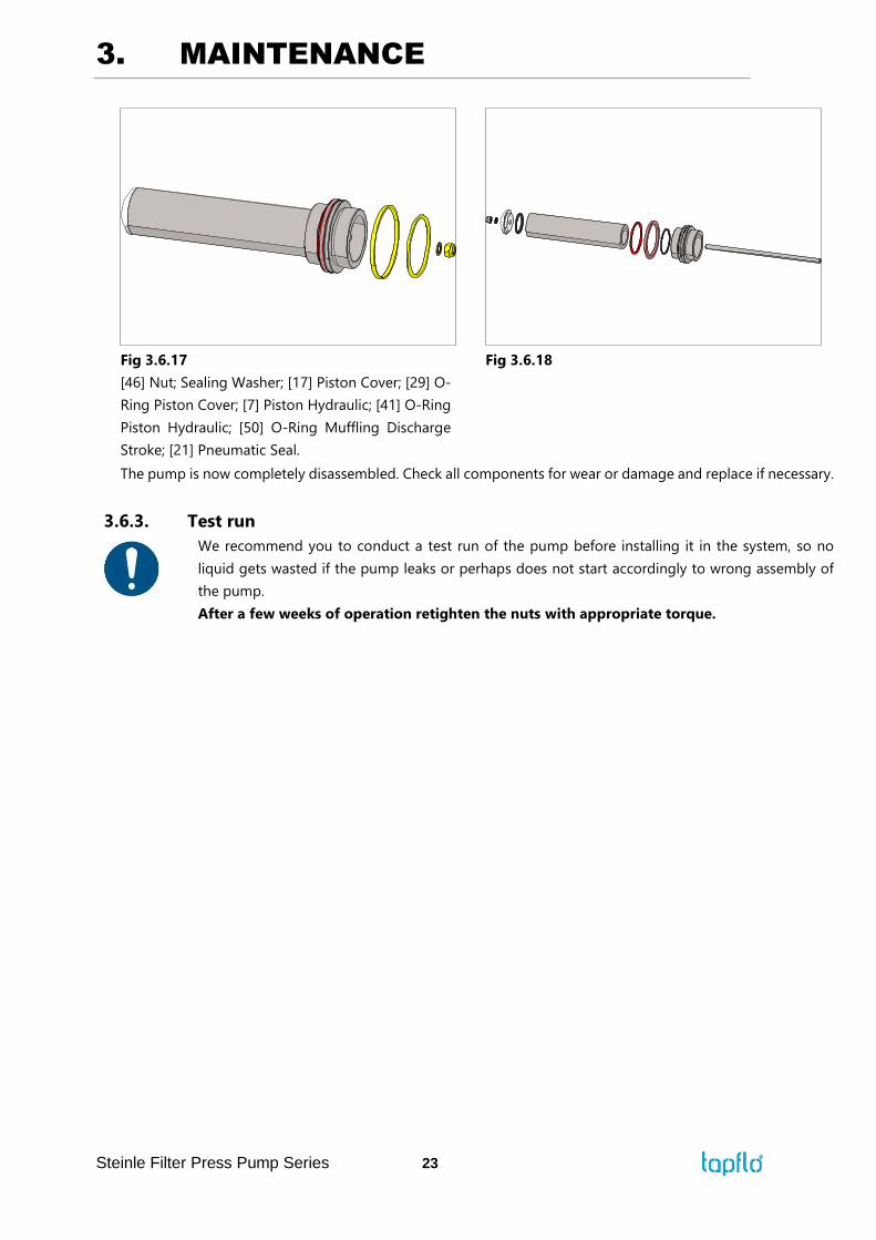
Fig 3.6.17
[46] Nut; Sealing Washer; [17] Piston Cover; [29] O-
Ring Piston Cover; [7] Piston Hydraulic; [41] O-Ring
Piston Hydraulic; [50] O-Ring Muffling Discharge
Stroke; [21] Pneumatic Seal.
Fig 3.6.18
The pump is now completely disassembled. Check all components for wear or damage and replace if necessary.
3.6.3. Test run
We recommend you to conduct a test run of the pump before installing it in the system, so no
liquid gets wasted if the pump leaks or perhaps does not start accordingly to wrong assembly of
the pump.
After a few weeks of operation retighten the nuts with appropriate torque.
3. MAINTENANCE
Steinle Filter Press Pump Series 24
3.7. FP/FH 40-80 – Disassembly of the pump
The numbers put in brackets, refer to the part numbers in the spare part drawings and spare part
lists in chapter 5 “Błąd! Wynik nieprawidłowy dla tabeli.”.
3.7.1. Before the disassembly procedure
Be sure to drain all liquid from the pump. Cleanse or neutralize the pump thoroughly.
Disconnect the air and the power supply and then the suction and discharge connections.
3.7.2. Disassembly procedure
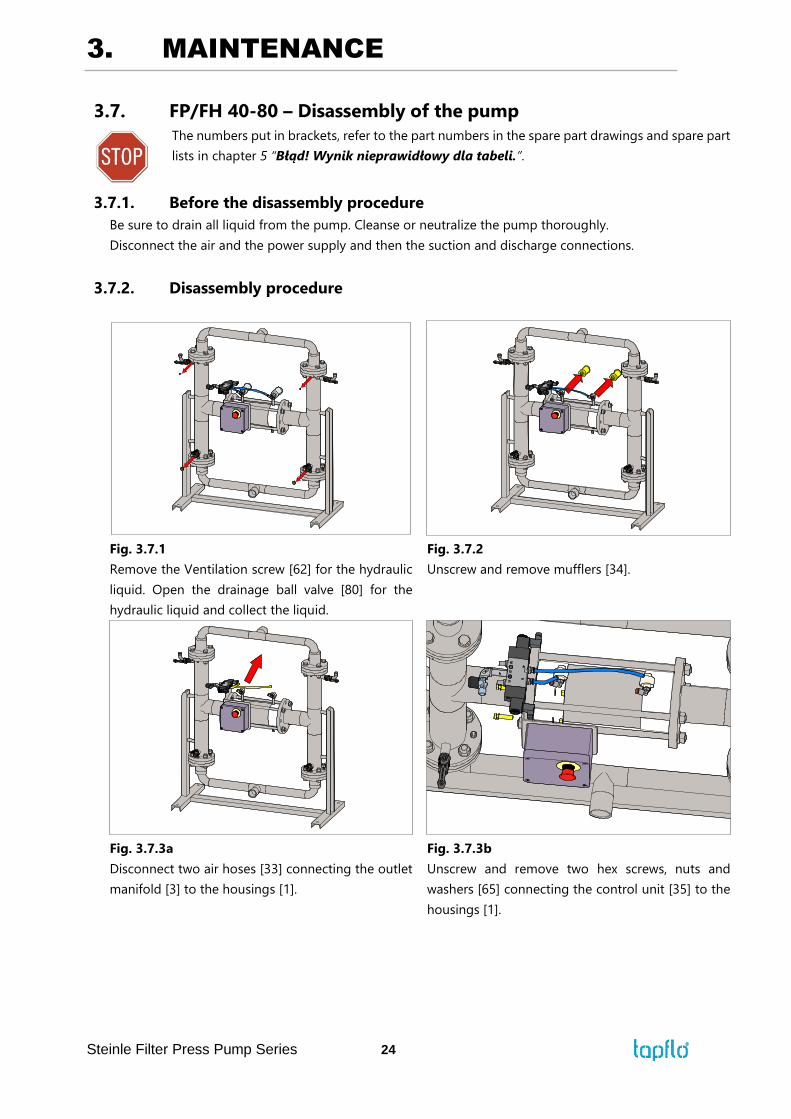
Fig. 3.7.1
Remove the Ventilation screw [62] for the hydraulic
liquid. Open the drainage ball valve [80] for the
hydraulic liquid and collect the liquid.
Fig. 3.7.2
Unscrew and remove mufflers [34].
Fig. 3.7.3a
Disconnect two air hoses [33] connecting the outlet
manifold [3] to the housings [1].
Fig. 3.7.3b
Unscrew and remove two hex screws, nuts and
washers [65] connecting the control unit [35] to the
housings [1].
3. MAINTENANCE
Steinle Filter Press Pump Series 25
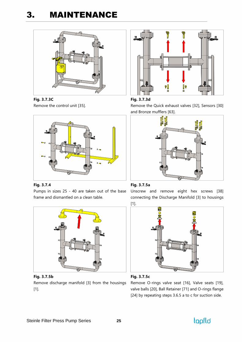
Fig. 3.7.3C
Remove the control unit [35].
Fig. 3.7.3d
Remove the Quick exhaust valves [32], Sensors [30]
and Bronze mufflers [63].
Fig. 3.7.4
Pumps in sizes 25 - 40 are taken out of the base
frame and dismantled on a clean table.
Fig. 3.7.5a
Unscrew and remove eight hex screws [38]
connecting the Discharge Manifold [3] to housings
[1].
Fig. 3.7.5b
Remove discharge manifold [3] from the housings
[1].
Fig. 3.7.5c
Remove O-rings valve seat [16], Valve seats [19],
valve balls [20], Ball Retainer [71] and O-rings flange
[24] by repeating steps 3.6.5 a to c for suction side.
3. MAINTENANCE
Steinle Filter Press Pump Series 26
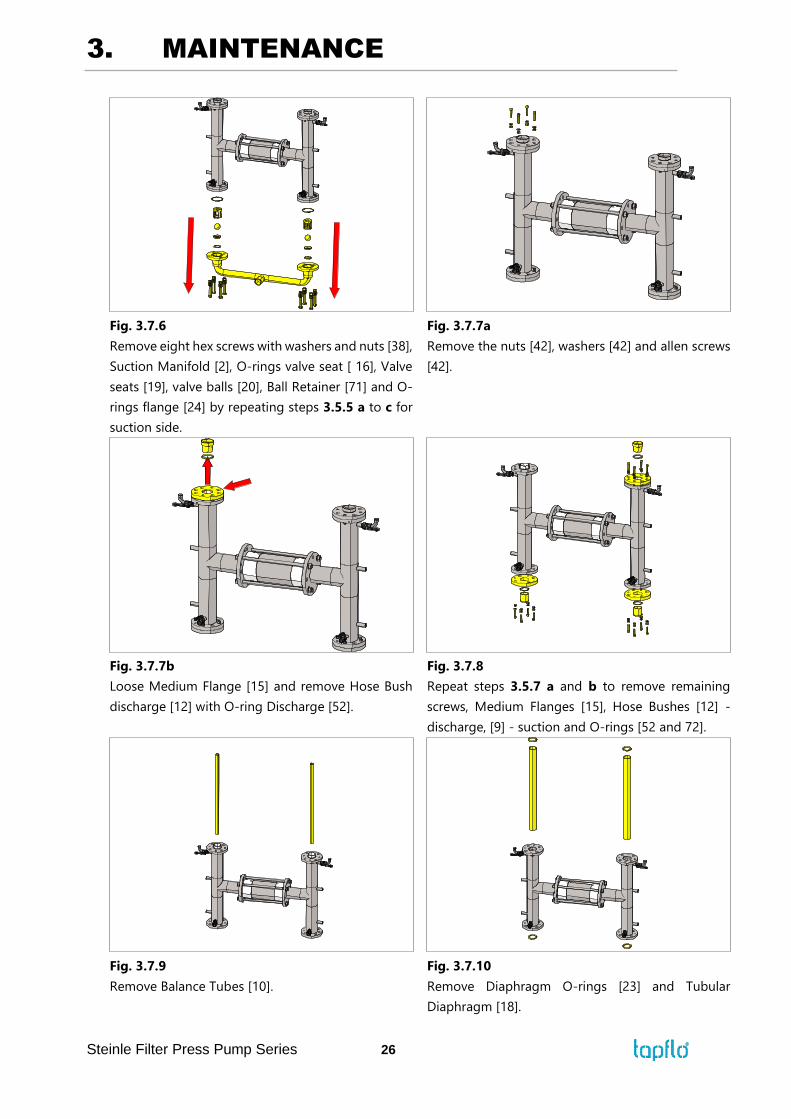
Fig. 3.7.6
Remove eight hex screws with washers and nuts [38],
Suction Manifold [2], O-rings valve seat [ 16], Valve
seats [19], valve balls [20], Ball Retainer [71] and O-
rings flange [24] by repeating steps 3.5.5 a to c for
suction side.
Fig. 3.7.7a
Remove the nuts [42], washers [42] and allen screws
[42].
Fig. 3.7.7b
Loose Medium Flange [15] and remove Hose Bush
discharge [12] with O-ring Discharge [52].
Fig. 3.7.8
Repeat steps 3.5.7 a and b to remove remaining
screws, Medium Flanges [15], Hose Bushes [12] -
discharge, [9] - suction and O-rings [52 and 72].
Fig. 3.7.9
Remove Balance Tubes [10].
Fig. 3.7.10
Remove Diaphragm O-rings [23] and Tubular
Diaphragm [18].
3. MAINTENANCE
Steinle Filter Press Pump Series 27
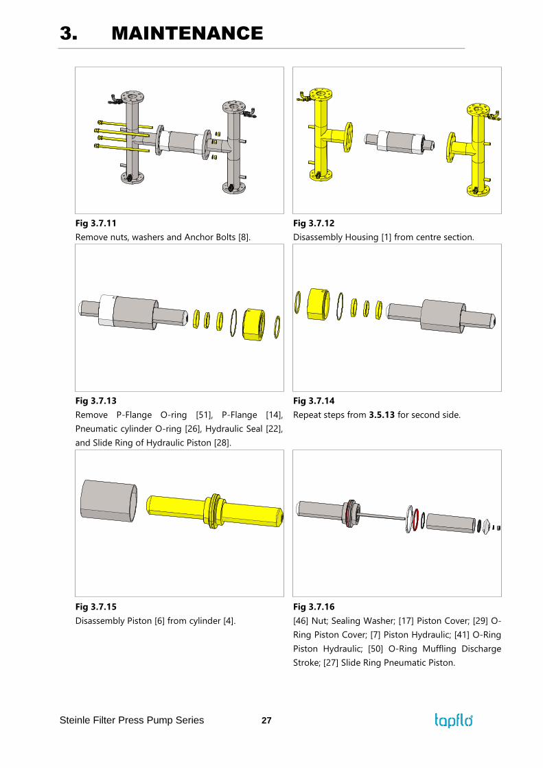
Fig 3.7.11
Remove nuts, washers and Anchor Bolts [8].
Fig 3.7.12
Disassembly Housing [1] from centre section.
Fig 3.7.13
Remove P-Flange O-ring [51], P-Flange [14],
Pneumatic cylinder O-ring [26], Hydraulic Seal [22],
and Slide Ring of Hydraulic Piston [28].
Fig 3.7.14
Repeat steps from 3.5.13 for second side.
Fig 3.7.15
Disassembly Piston [6] from cylinder [4].
Fig 3.7.16
[46] Nut; Sealing Washer; [17] Piston Cover; [29] O-
Ring Piston Cover; [7] Piston Hydraulic; [41] O-Ring
Piston Hydraulic; [50] O-Ring Muffling Discharge
Stroke; [27] Slide Ring Pneumatic Piston.
3. MAINTENANCE
Steinle Filter Press Pump Series 28
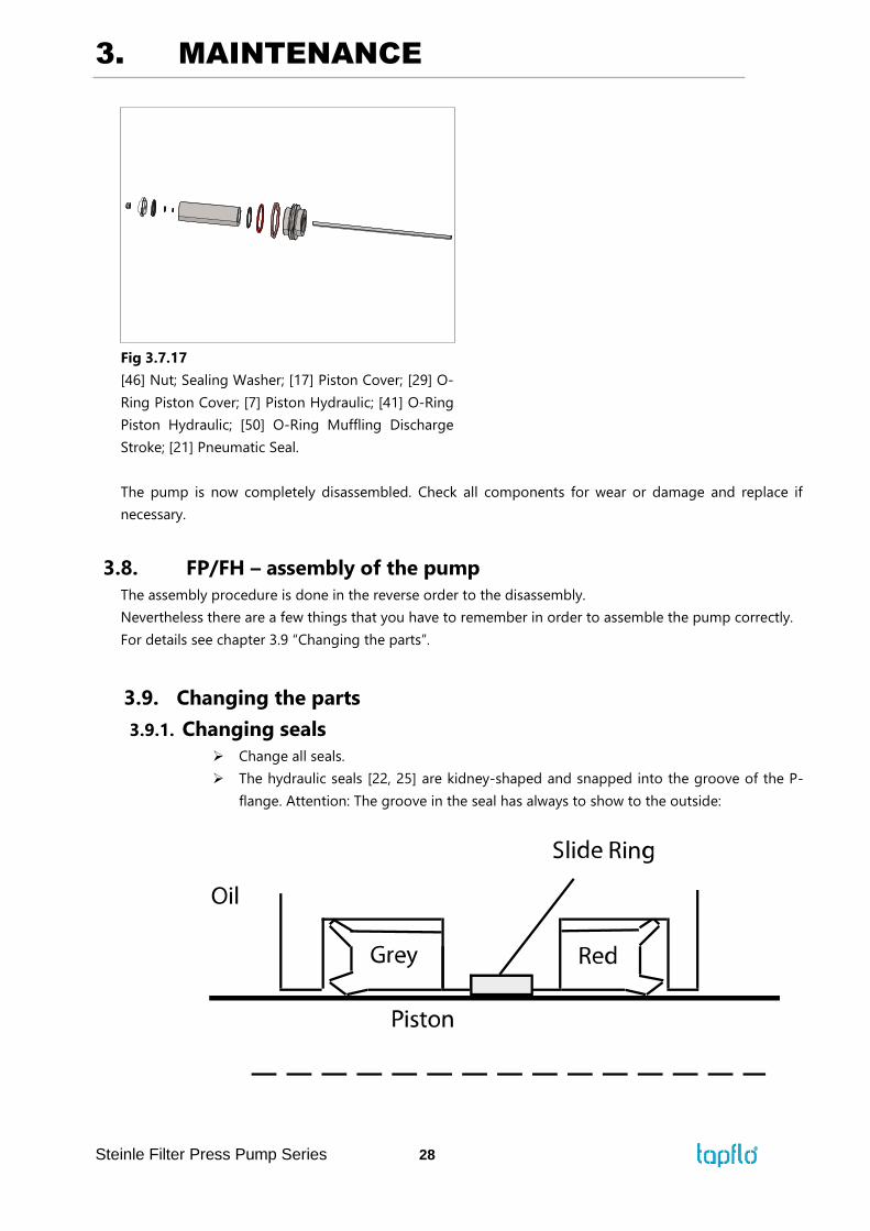
Fig 3.7.17
[46] Nut; Sealing Washer; [17] Piston Cover; [29] O-
Ring Piston Cover; [7] Piston Hydraulic; [41] O-Ring
Piston Hydraulic; [50] O-Ring Muffling Discharge
Stroke; [21] Pneumatic Seal.
The pump is now completely disassembled. Check all components for wear or damage and replace if
necessary.
3.8. FP/FH – assembly of the pump
The assembly procedure is done in the reverse order to the disassembly.
Nevertheless there are a few things that you have to remember in order to assemble the pump correctly.
For details see chapter 3.9 “Changing the parts”.
3.9. Changing the parts
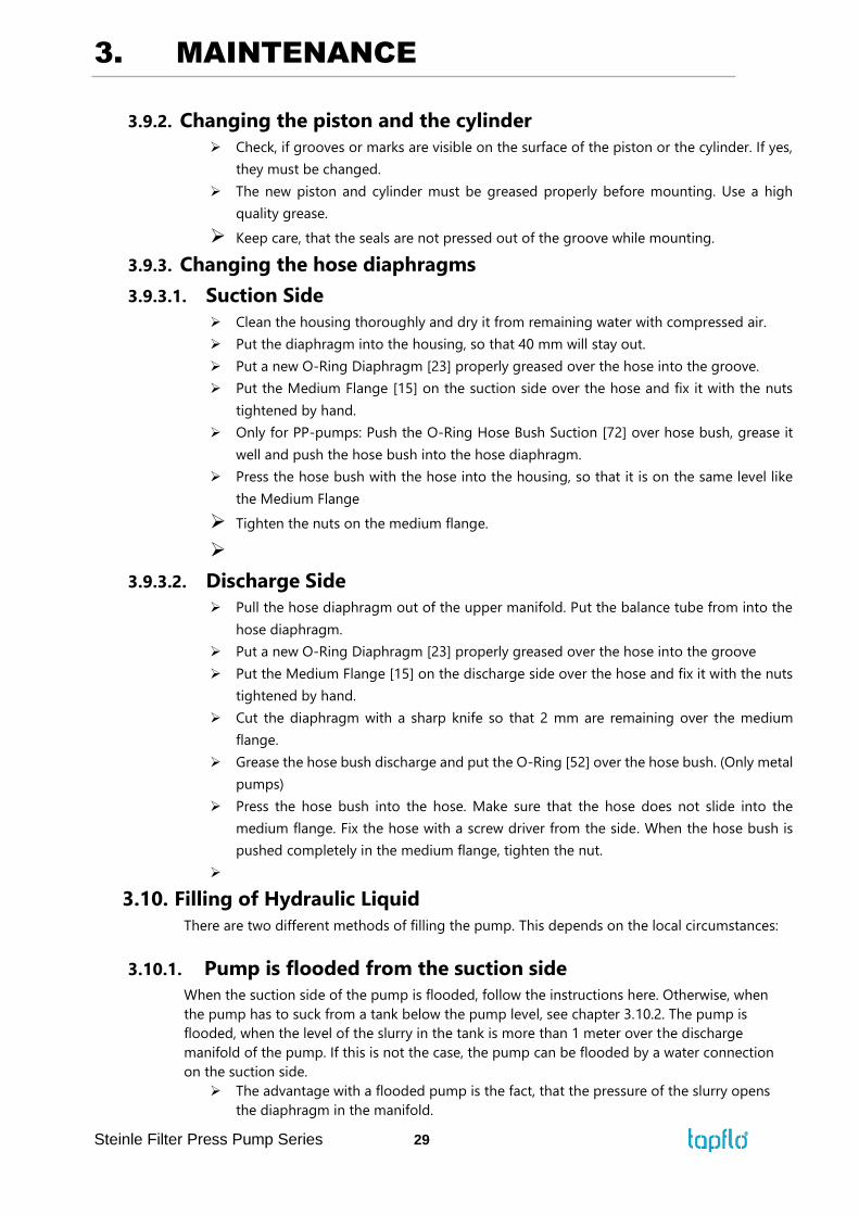
3.9.1. Changing seals
➢ Change all seals.
➢ The hydraulic seals [22, 25] are kidney-shaped and snapped into the groove of the P-
flange. Attention: The groove in the seal has always to show to the outside:
3. MAINTENANCE
Steinle Filter Press Pump Series 29
3.9.2. Changing the piston and the cylinder
➢ Check, if grooves or marks are visible on the surface of the piston or the cylinder. If yes,
they must be changed.
➢ The new piston and cylinder must be greased properly before mounting. Use a high
quality grease.
➢ Keep care, that the seals are not pressed out of the groove while mounting.
3.9.3. Changing the hose diaphragms
3.9.3.1. Suction Side
➢ Clean the housing thoroughly and dry it from remaining water with compressed air.
➢ Put the diaphragm into the housing, so that 40 mm will stay out.
➢ Put a new O-Ring Diaphragm [23] properly greased over the hose into the groove.
➢ Put the Medium Flange [15] on the suction side over the hose and fix it with the nuts
tightened by hand.
➢ Only for PP-pumps: Push the O-Ring Hose Bush Suction [72] over hose bush, grease it
well and push the hose bush into the hose diaphragm.
➢ Press the hose bush with the hose into the housing, so that it is on the same level like
the Medium Flange
➢ Tighten the nuts on the medium flange.
➢
3.9.3.2. Discharge Side
➢ Pull the hose diaphragm out of the upper manifold. Put the balance tube from into the
hose diaphragm.
➢ Put a new O-Ring Diaphragm [23] properly greased over the hose into the groove
➢ Put the Medium Flange [15] on the discharge side over the hose and fix it with the nuts
tightened by hand.
➢ Cut the diaphragm with a sharp knife so that 2 mm are remaining over the medium
flange.
➢ Grease the hose bush discharge and put the O-Ring [52] over the hose bush. (Only metal
pumps)
➢ Press the hose bush into the hose. Make sure that the hose does not slide into the
medium flange. Fix the hose with a screw driver from the side. When the hose bush is
pushed completely in the medium flange, tighten the nut.
➢
3.10. Filling of Hydraulic Liquid
There are two different methods of filling the pump. This depends on the local circumstances:
3.10.1. Pump is flooded from the suction side
When the suction side of the pump is flooded, follow the instructions here. Otherwise, when
the pump has to suck from a tank below the pump level, see chapter 3.10.2. The pump is
flooded, when the level of the slurry in the tank is more than 1 meter over the discharge
manifold of the pump. If this is not the case, the pump can be flooded by a water connection
on the suction side.
➢ The advantage with a flooded pump is the fact, that the pressure of the slurry opens
the diaphragm in the manifold.
3. MAINTENANCE
Steinle Filter Press Pump Series 30
➢ The pump has to be assembled complete and installed in the plant with all
connections.
➢ The valve from the slurry tank has to be opened, so that the slurry flows into the pump
➢ to open the hose diaphragm.
➢ Switch off the control power and leave the air supply open.
➢ Operate the hand operation on the left side of the solenoid valve, so that the piston
moves to the right side. Now the left side of the housing can be filled.
➢ Close the drain nozzle on the downside of the housing.
➢ Open the oil filling nozzle on the top of the housing
➢ Screw out the ventilation screw ( 4 mm) from the side of the lower flange on the top of
the pump.
➢ Fill in the oil, till it comes out of the ventilation hole.
➢ Screw in the ventilation screw.
➢ Close the filling nozzle. Single acting pump (FP25) is now ready for operation. At the
double acting pumps now the hand operation on the right side has to be operated, so
that the piston moves to the left side. Attention! Piston moves only, when the valve on
the discharge is opened. Now the right side can be filled like described above.
➢ Switch on the control power and let the pump run.
3.10.2. Pump is not flooded
When the pump is not flooded, the following steps has to be done:
The pump has be assembled without the discharge manifold
➢ Connect the air supply.
➢ Operate the hand operation on the right side of the solenoid valve, so that the piston
moves to the left side. Now the left side can be filled.
➢ Close the drain nozzle on the downside of the housing.
➢ Open the oil filling nozzle on the top of the housing
➢ Screw out the ventilation screw ( 4 mm) from the side of the lower flange on the top of
the pump.
➢ Fill in the oil, till it comes out of the ventilation hole.
➢ Screw in the ventilation screw.
➢ Close the filling nozzle. Single acting pump (FP25) is now ready for operation. At the
double acting pumps now the hand operation on the left side has to be operated, so
that the piston moves to the right side. Attention! Piston moves only, when the valve
on the discharge is opened. Now the right side can be filled like described above.
➢ Switch on the control power and let the pump run.
3.10.3. Changing stroke sensors
In case that a stroke sensor must be changed screw out the old sensor by locking the two nuts
against each other in the position they have. Measure the distance from the sensor face to the
next nut and adjust the nuts on the new sensor in the same way. Attention! Before a new sensor
is screwed into the P-flange move the pneumatic piston manually by pressing the small button
on the air valve into this position where the new sensor will be screwed in. When no distance
from the old sensor is available, screw the new sensor carefully into the P-flange till it touches
the pneumatic piston and turn it back half a round.
3.10.4. Test run
We recommend you to conduct a test run of the pump before installing it in the system, so no
liquid gets wasted if the pump leaks or perhaps does not start accordingly to wrong assembly
of the pump. After a few weeks of operation retighten the nuts with appropriate torque.
4. SPARE PARTS
Steinle Filter Press Pump Series 31
4. SPARE PARTS
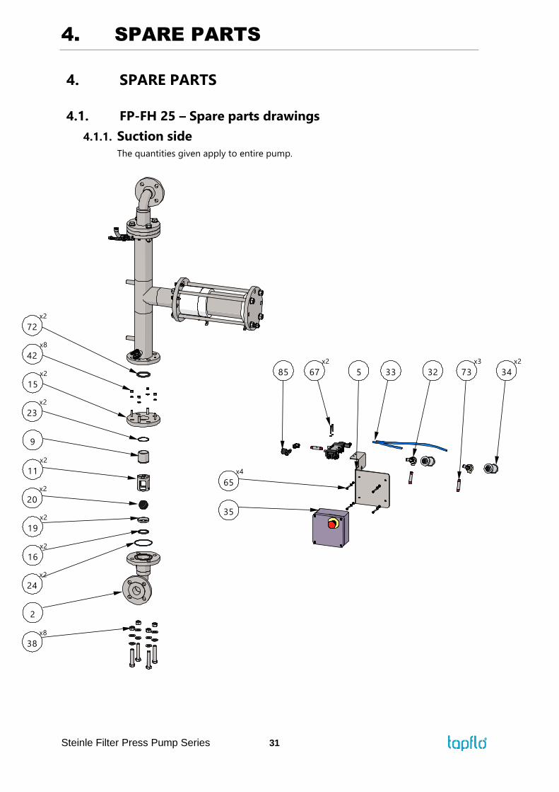
4.1. FP-FH 25 – Spare parts drawings
4.1.1. Suction side
The quantities given apply to entire pump.
x
3
2
x2
24
16
x2
20
x2
19
x2
11
x2
15
x2
9
x2
23
x
42
x2
72
34
x2
32 73
x3
5 3367
x2
5
x4
65
35
4. SPARE PARTS
Steinle Filter Press Pump Series 32
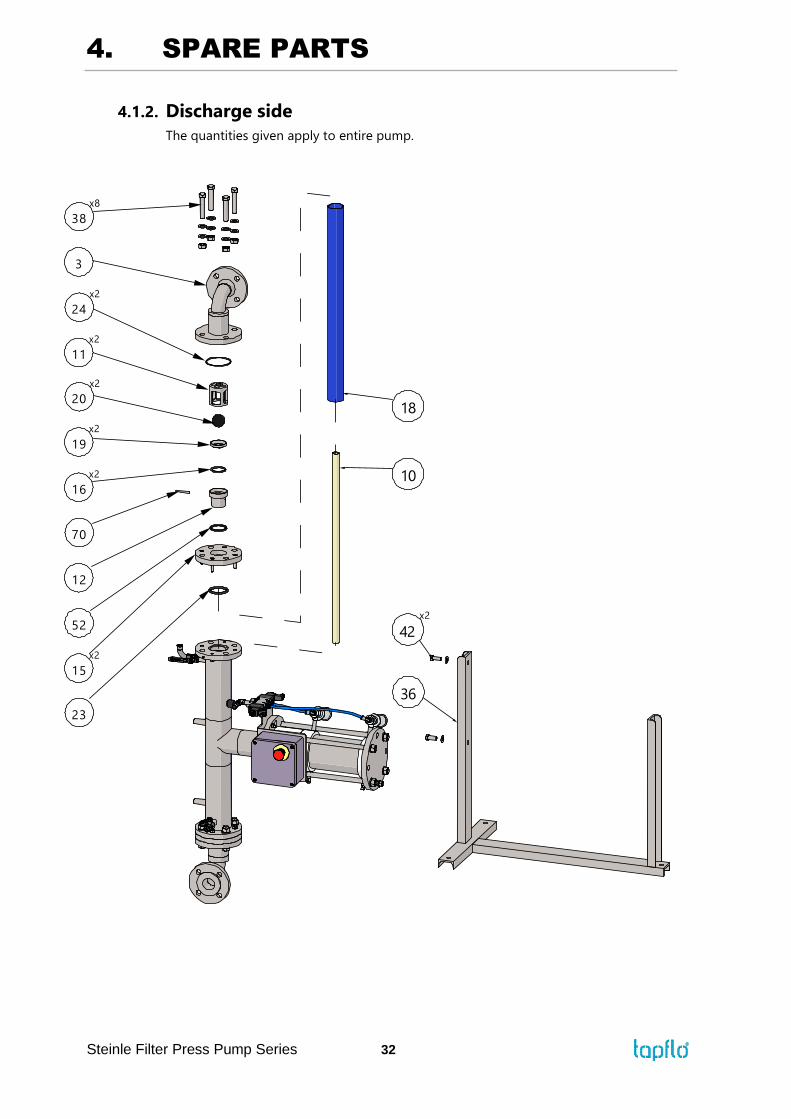
4.1.2. Discharge side
The quantities given apply to entire pump.
36
42
x2
23
15
x2
52
12
70
x2
16
x2
19
x2
20
11
x2
3
x2
24
10
1
x
3
4. SPARE PARTS
Steinle Filter Press Pump Series 33
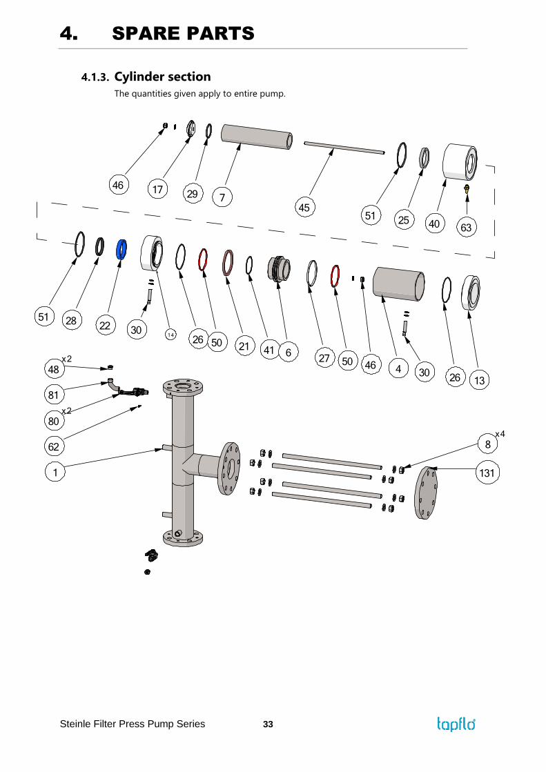
4.1.3. Cylinder section
The quantities given apply to entire pump.
4. SPARE PARTS
Steinle Filter Press Pump Series 34
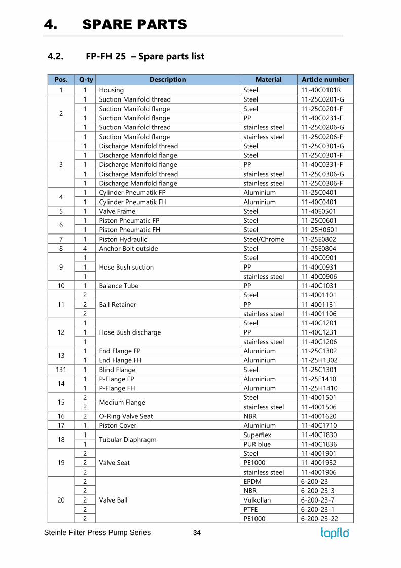
4.2. FP-FH 25 – Spare parts list
Pos. Q-ty Description Material Article number
1 1 Housing Steel 11-40C0101R
2
1 Suction Manifold thread Steel 11-25C0201-G
1 Suction Manifold flange Steel 11-25C0201-F
1 Suction Manifold flange PP 11-40C0231-F
1 Suction Manifold thread stainless steel 11-25C0206-G
1 Suction Manifold flange stainless steel 11-25C0206-F
3
1 Discharge Manifold thread Steel 11-25C0301-G
1 Discharge Manifold flange Steel 11-25C0301-F
1 Discharge Manifold flange PP 11-40C0331-F
1 Discharge Manifold thread stainless steel 11-25C0306-G
1 Discharge Manifold flange stainless steel 11-25C0306-F
4 1 Cylinder Pneumatik FP Aluminium 11-25C0401
1 Cylinder Pneumatik FH Aluminium 11-40C0401
5 1 Valve Frame Steel 11-40E0501
6 1 Piston Pneumatic FP Steel 11-25C0601
1 Piston Pneumatic FH Steel 11-25H0601
7 1 Piston Hydraulic Steel/Chrome 11-25E0802
8 4 Anchor Bolt outside Steel 11-25E0804
9
1
Hose Bush suction
Steel 11-40C0901
1 PP 11-40C0931
1 stainless steel 11-40C0906
10 1 Balance Tube PP 11-40C1031
11
2
Ball Retainer
Steel 11-4001101
2 PP 11-4001131
2 stainless steel 11-4001106
12
1
Hose Bush discharge
Steel 11-40C1201
1 PP 11-40C1231
1 stainless steel 11-40C1206
13 1 End Flange FP Aluminium 11-25C1302
1 End Flange FH Aluminium 11-25H1302
131 1 Blind Flange Steel 11-25C1301
14 1 P-Flange FP Aluminium 11-25E1410
1 P-Flange FH Aluminium 11-25H1410
15 2
Medium Flange Steel 11-4001501
2 stainless steel 11-4001506
16 2 O-Ring Valve Seat NBR 11-4001620
17 1 Piston Cover Aluminium 11-40C1710
18 1
Tubular Diaphragm Superflex 11-40C1830
1 PUR blue 11-40C1836
19
2
Valve Seat
Steel 11-4001901
2 PE1000 11-4001932
2 stainless steel 11-4001906
20
2
Valve Ball
EPDM 6-200-23
2 NBR 6-200-23-3
2 Vulkollan 6-200-23-7
2 PTFE 6-200-23-1
2 PE1000 6-200-23-22
4. SPARE PARTS
Steinle Filter Press Pump Series 35
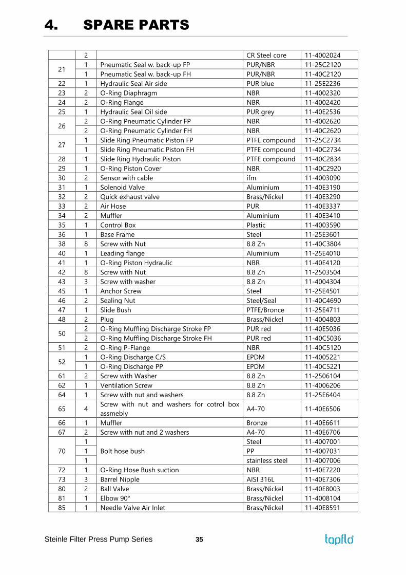
2 CR Steel core 11-4002024
21 1 Pneumatic Seal w. back-up FP PUR/NBR 11-25C2120
1 Pneumatic Seal w. back-up FH PUR/NBR 11-40C2120
22 1 Hydraulic Seal Air side PUR blue 11-25E2236
23 2 O-Ring Diaphragm NBR 11-4002320
24 2 O-Ring Flange NBR 11-4002420
25 1 Hydraulic Seal Oil side PUR grey 11-40E2536
26 2 O-Ring Pneumatic Cylinder FP NBR 11-4002620
2 O-Ring Pneumatic Cylinder FH NBR 11-40C2620
27 1 Slide Ring Pneumatic Piston FP PTFE compound 11-25C2734
1 Slide Ring Pneumatic Piston FH PTFE compound 11-40C2734
28 1 Slide Ring Hydraulic Piston PTFE compound 11-40C2834
29 1 O-Ring Piston Cover NBR 11-40C2920
30 2 Sensor with cable ifm 11-4003090
31 1 Solenoid Valve Aluminium 11-40E3190
32 2 Quick exhaust valve Brass/Nickel 11-40E3290
33 2 Air Hose PUR 11-40E3337
34 2 Muffler Aluminium 11-40E3410
35 1 Control Box Plastic 11-4003590
36 1 Base Frame Steel 11-25E3601
38 8 Screw with Nut 8.8 Zn 11-40C3804
40 1 Leading flange Aluminium 11-25E4010
41 1 O-Ring Piston Hydraulic NBR 11-40E4120
42 8 Screw with Nut 8.8 Zn 11-2503504
43 3 Screw with washer 8.8 Zn 11-4004304
45 1 Anchor Screw Steel 11-25E4501
46 2 Sealing Nut Steel/Seal 11-40C4690
47 1 Slide Bush PTFE/Bronce 11-25E4711
48 2 Plug Brass/Nickel 11-4004803
50 2 O-Ring Muffling Discharge Stroke FP PUR red 11-40E5036
2 O-Ring Muffling Discharge Stroke FH PUR red 11-40C5036
51 2 O-Ring P-Flange NBR 11-40C5120
52 1 O-Ring Discharge C/S EPDM 11-4005221
1 O-Ring Discharge PP EPDM 11-40C5221
61 2 Screw with Washer 8.8 Zn 11-2506104
62 1 Ventilation Screw 8.8 Zn 11-4006206
64 1 Screw with nut and washers 8.8 Zn 11-25E6404
65 4 Screw with nut and washers for cotrol box
assmebly A4-70 11-40E6506
66 1 Muffler Bronze 11-40E6611
67 2 Screw with nut and 2 washers A4-70 11-40E6706
70
1
Bolt hose bush
Steel 11-4007001
1 PP 11-4007031
1 stainless steel 11-4007006
72 1 O-Ring Hose Bush suction NBR 11-40E7220
73 3 Barrel Nipple AISI 316L 11-40E7306
80 2 Ball Valve Brass/Nickel 11-40E8003
81 1 Elbow 90° Brass/Nickel 11-4008104
85 1 Needle Valve Air Inlet Brass/Nickel 11-40E8591
4. SPARE PARTS
Steinle Filter Press Pump Series 36
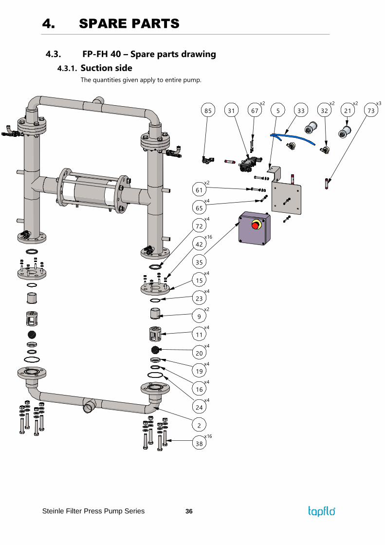
4.3. FP-FH 40 – Spare parts drawing
4.3.1. Suction side
The quantities given apply to entire pump.
x16
3
2
24
x4
16
x4
19
x4
20
x4
x4
11
23
x4
x2
9
x4
15
42
x16
72
x4
21
x2
5 31
x2
61
67
x2
5 73
x3
33 32
x2
x4
65
35
4. SPARE PARTS
Steinle Filter Press Pump Series 37
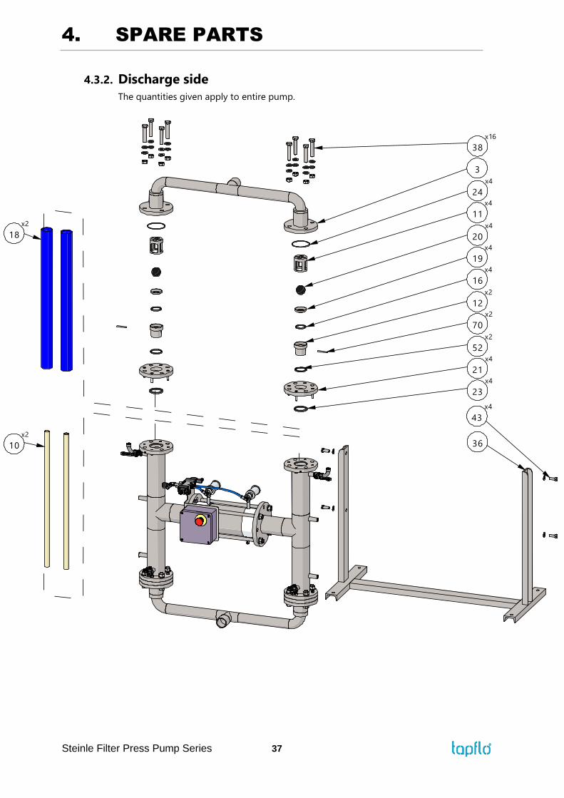
4.3.2. Discharge side
The quantities given apply to entire pump.
36
x4
43
10
x2
x2
1
23
x4
52
x2
21
x4
x2
12
70
x2
x4
16
x4
19
20
x4
11
x4
3
x4
24
3
x16
4. SPARE PARTS
Steinle Filter Press Pump Series 38
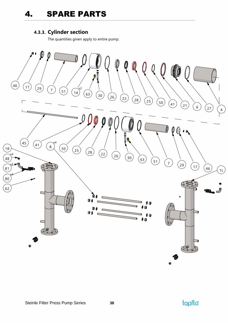
4.3.3. Cylinder section
The quantities given apply to entire pump.
x2
1
4
x4
1
0
x4
41x4
45
51
50
62
252
46
3022
17
1
29
6326
763 30
7
51
17
26
x2
14
2946
22 2 254150
21 6 27 4
4. SPARE PARTS
Steinle Filter Press Pump Series 39
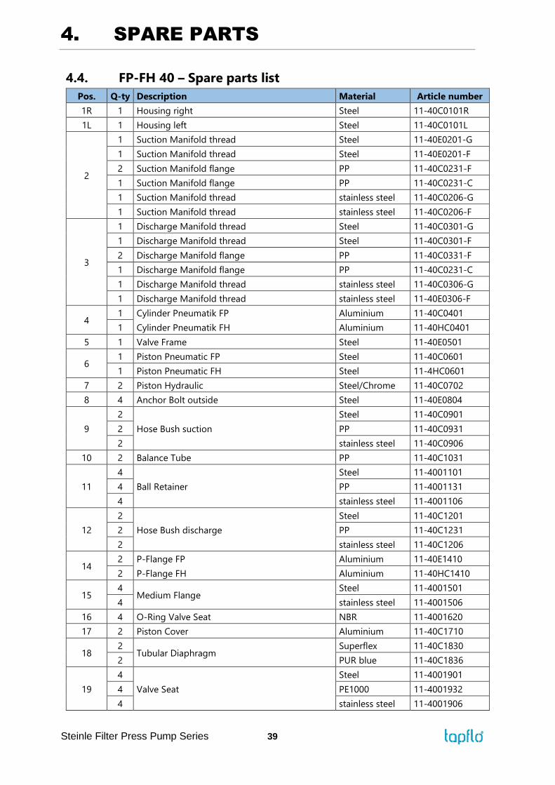
4.4. FP-FH 40 – Spare parts list
Pos. Q-ty Description Material Article number
1R 1 Housing right Steel 11-40C0101R
1L 1 Housing left Steel 11-40C0101L
2
1 Suction Manifold thread Steel 11-40E0201-G
1 Suction Manifold thread Steel 11-40E0201-F
2 Suction Manifold flange PP 11-40C0231-F
1 Suction Manifold flange PP 11-40C0231-C
1 Suction Manifold thread stainless steel 11-40C0206-G
1 Suction Manifold thread stainless steel 11-40C0206-F
3
1 Discharge Manifold thread Steel 11-40C0301-G
1 Discharge Manifold thread Steel 11-40C0301-F
2 Discharge Manifold flange PP 11-40C0331-F
1 Discharge Manifold flange PP 11-40C0231-C
1 Discharge Manifold thread stainless steel 11-40C0306-G
1 Discharge Manifold thread stainless steel 11-40E0306-F
4 1 Cylinder Pneumatik FP Aluminium 11-40C0401
1 Cylinder Pneumatik FH Aluminium 11-40HC0401
5 1 Valve Frame Steel 11-40E0501
6 1 Piston Pneumatic FP Steel 11-40C0601
1 Piston Pneumatic FH Steel 11-4HC0601
7 2 Piston Hydraulic Steel/Chrome 11-40C0702
8 4 Anchor Bolt outside Steel 11-40E0804
9
2
Hose Bush suction
Steel 11-40C0901
2 PP 11-40C0931
2 stainless steel 11-40C0906
10 2 Balance Tube PP 11-40C1031
11
4
Ball Retainer
Steel 11-4001101
4 PP 11-4001131
4 stainless steel 11-4001106
12
2
Hose Bush discharge
Steel 11-40C1201
2 PP 11-40C1231
2 stainless steel 11-40C1206
14 2 P-Flange FP Aluminium 11-40E1410
2 P-Flange FH Aluminium 11-40HC1410
15 4
Medium Flange Steel 11-4001501
4 stainless steel 11-4001506
16 4 O-Ring Valve Seat NBR 11-4001620
17 2 Piston Cover Aluminium 11-40C1710
18 2
Tubular Diaphragm Superflex 11-40C1830
2 PUR blue 11-40C1836
19
4
Valve Seat
Steel 11-4001901
4 PE1000 11-4001932
4 stainless steel 11-4001906
4. SPARE PARTS
Steinle Filter Press Pump Series 40
20
4
Valve Ball
EPDM 6-200-23
4 NBR 6-200-23-3
4 Vulkollan 6-200-23-7
4 PTFE 6-200-23-1
4 PE1000 6-200-23-22
4 CR Steel core 11-4002024
21 1 Pneumatic Seal w. back-up FP PUR/NBR 11-40C2120
1 Pneumatic Seal w. back-up FH PUR/NBR 11-4HC2120
22 2 Hydraulic Seal Air side PUR red 11-40E2236
23 4 O-Ring Diaphragm NBR 11-4002320
24 4 O-Ring Flange NBR 11-4002420
25 2 Hydraulic Seal Oil side PUR grey 11-40E2536
26 2 O-Ring Pneumatic Cylinder FP NBR 11-40C2620
2 O-Ring Pneumatic Cylinder FH NBR 11-4HC2620
27 1 Slide Ring Pneumatic Piston FP PTFE compound 11-40C2734
1 Slide Ring Pneumatic Piston FH PTFE compound 11-4HC2734
28 2 Slide Ring Hydraulic Piston PTFE compound 11-40C2834
29 2 O-Ring Piston Cover NBR 11-40C2920
30 2 Sensor with cable ifm 11-4003090
31 1 Solenoid Valve Aluminium 11-40E3190
32 2 Quick exhaust valve Brass/Nickel 11-40E3290
33 2 Air Hose PUR 11-40E3337
34 2 Muffler Aluminium 11-40E3410
35 1 Control Box Plastic 11-4003590
36 1 Base Frame Steel 11-40E3601
38 16 Screw with Nut 8.8 Zn 11-40C3804
41 2 O-Ring Piston Hydraulic NBR 11-40E4120
42 16 Screw with Nut 8.8 Zn 11-2503504
43 4 Screw with washer 8.8 Zn 11-40E4304
45 1 Anchor Screw Steel 11-40E4504
46 2 Sealing Nut Steel/Seal 11-40C4690
48 4 Plug Brass/Nickel 11-4004803
50 2 O-Ring Muffling Discharge Stroke PUR red 11-40C5036
51 2 O-Ring P-Flange NBR 11-40C5120
52 2 O-Ring Discharge C/S EPDM 11-4005221
2 O-Ring Discharge PP EPDM 11-40C5221
61 2 Screw with Washer 8.8 Zn 11-2506104
62 2 Ventilation Screw 8.8 Zn 11-50E6206
65 2 Screw with nut and washers for cotrol box
assmebly A4-70 11-40E6506
66 2 Muffler Bronze 11-40E6611
67 4 Screw with nut and 2 washers A4-70 11-40E6706
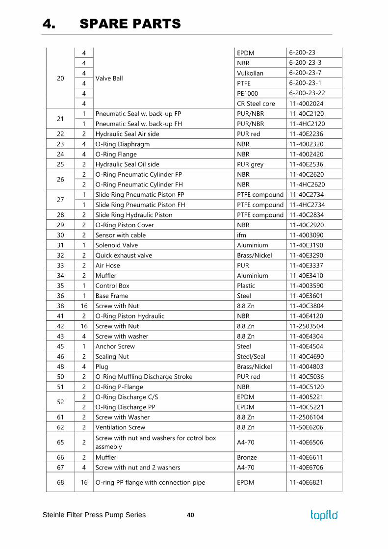
68 16 O-ring PP flange with connection pipe EPDM 11-40E6821
4. SPARE PARTS
Steinle Filter Press Pump Series 41
69 2 Screw with nut and washers for PP flange with
connection pipe St 8.8 Zn 11-40E6904
70
2
Bolt hose bush
Steel 11-4007001
2 PP 11-4007031
2 stainless steel 11-4007006
72 3 O-Ring Hose Bush suction NBR 11-40E7220
73 4 Barrel Nipple AISI 316L 11-40E7306
80 2 Ball Valve Brass/Nickel 11-40E8003
81 1 Elbow 90° Brass/Nickel 11-4008104
85 6 Needle Valve Air Inlet Brass/Nickel 11-40E8591

4. SPARE PARTS
Steinle Filter Press Pump Series 42
4.5. FP-FH 50/80 – Spare parts drawing
4.5.1. Suction side
The quantities given apply to entire pump.
x16
3
2
24
x4
16
x4
19
x4
20
x4
x4
11
23
x4
x2
9
x4
15
42
x16
72
x4
21
x2
5 31
x2
61
67
x2
5 73
x3
33 32
x2
x4
65
35

4. SPARE PARTS
Steinle Filter Press Pump Series 43
4.5.2. Discharge side
The quantities given apply to entire pump.
4.5.3. Cylinder section
43
x410
x2
36
1
x2
23
x4
x4
52
x4
15
12
x2
70
x2
46
x2
20
x4
11
x4
3
x4
24
x16
3
4. SPARE PARTS
Steinle Filter Press Pump Series 44
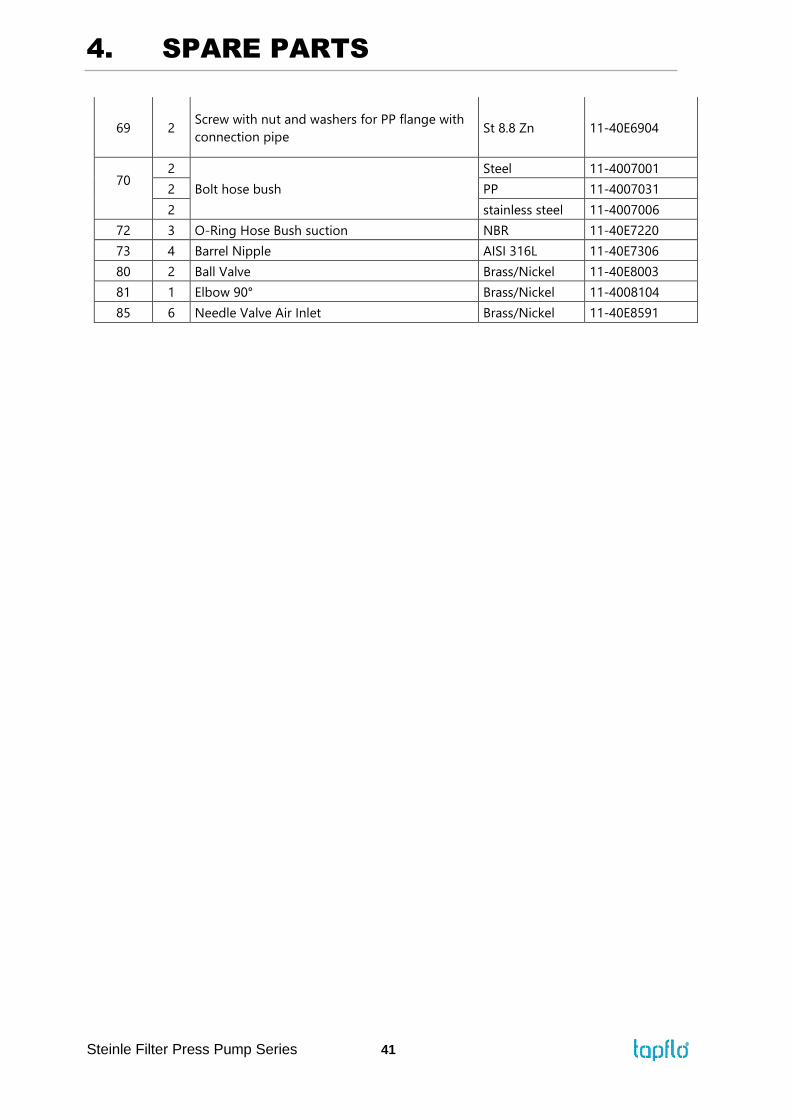
The quantities given apply to entire pump.
4.6. FP-FH 50/80 – Spare parts list
x2
1
4
x4
1
0
x4
41x4
45
51
50
62
252
46
3022
17
1
29
6326
763 30
7
51
17
26
x2
14
2946
22 2 254150
21 6 27 4
4. SPARE PARTS
Steinle Filter Press Pump Series 45
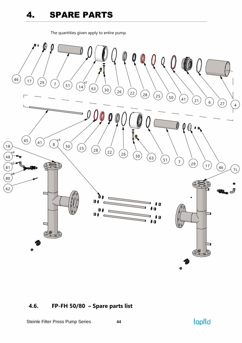
Pos. Q-ty Description Material Article number
1 1 Housing right steel 11-50C0101-R
1 Housing left steel 11-50C0101-L
2
1 Suction Manifold thread 50 steel 11-50C0201
2 Suction Manifold flange 50 PP without
material 11-50C0231
1 Suction Manifold flange 50 PP 11-50C0231-C
1 Suction Manifold thread 50 stainless steel 11-50C0206
1 Suction Manifold thread 80 steel 11-80C0201
2 Suction Manifold flange 80 PP without
material 11-80C0231
1 Suction Manifold flange 80 PP 11-80C0231-C
1 Suction Manifold thread 80 stainless steel 11-80C0206
3
1 Discharge Manifold thread 50 steel 11-50C0301
2 Discharge Manifold flange 50 PP 11-50C0331
1 Discharge Manifold flange 50 PP 11-50C0231-C
1 Discharge Manifold thread 50 stainless steel 11-50C0306
1 Discharge Manifold thread 80 steel 11-80C0301
2 Discharge Manifold flange 80 PP 11-80C0331
1 Discharge Manifold flange 80 PP 11-80C0231-C
1 Discharge Manifold thread 80 stainless steel 11-80C0306
4 1 Cylinder Pneumatik FP Aluminium 11-50C0401
1 Cylinder Pneumatik FH Aluminium 11-5HC0401
5 1 Valve Frame Steel 11-50C0501
6 1 Piston Pneumatic FP Steel 11-50C0610
1 Piston Pneumatic FH Steel 11-5HC0610
7 2 Piston Hydraulic Aluminum 11-50E0701
8 6 Anchor Bolt outside St60 11-50C0804
9
2
Hose Bush suction for Superflex diaphragm
steel 11-5000901
2 PP 11-5000931
2 stainless steel 11-5000906
2
Hose Bush suction for PUR diaphragm
steel 11-5000901-U
2 PP 11-5000931-U
2 stainless steel 11-5000906-U
10 2 Balance Tube PP 11-50C1031
11
4
Ball Retainer
steel 11-5001101
4 PP 11-5001131
4 stainless steel 11-5001106
12
2
Hose Bush discharge for Superflex diaphragm
steel 11-5001201
2 PP 11-5001231
2 stainless steel 11-5001206
2
Hose Bush discharge for PUR diaphragm
steel 11-5001201-U
2 PP 11-5001231-U
2 stainless steel 11-5001206-U
14 2 P-Flange FP Aluminum 11-50E1410
2 P-Flange FH Aluminum 11-5HE1410
15 4
Medium Flange steel 11-5001501
4 stainless steel 11-5001506
16 2 O-Ring Valve Seat NBR 11-5001620
17 2 Piston Cover Aluminum 11-50C1710
4. SPARE PARTS
Steinle Filter Press Pump Series 46
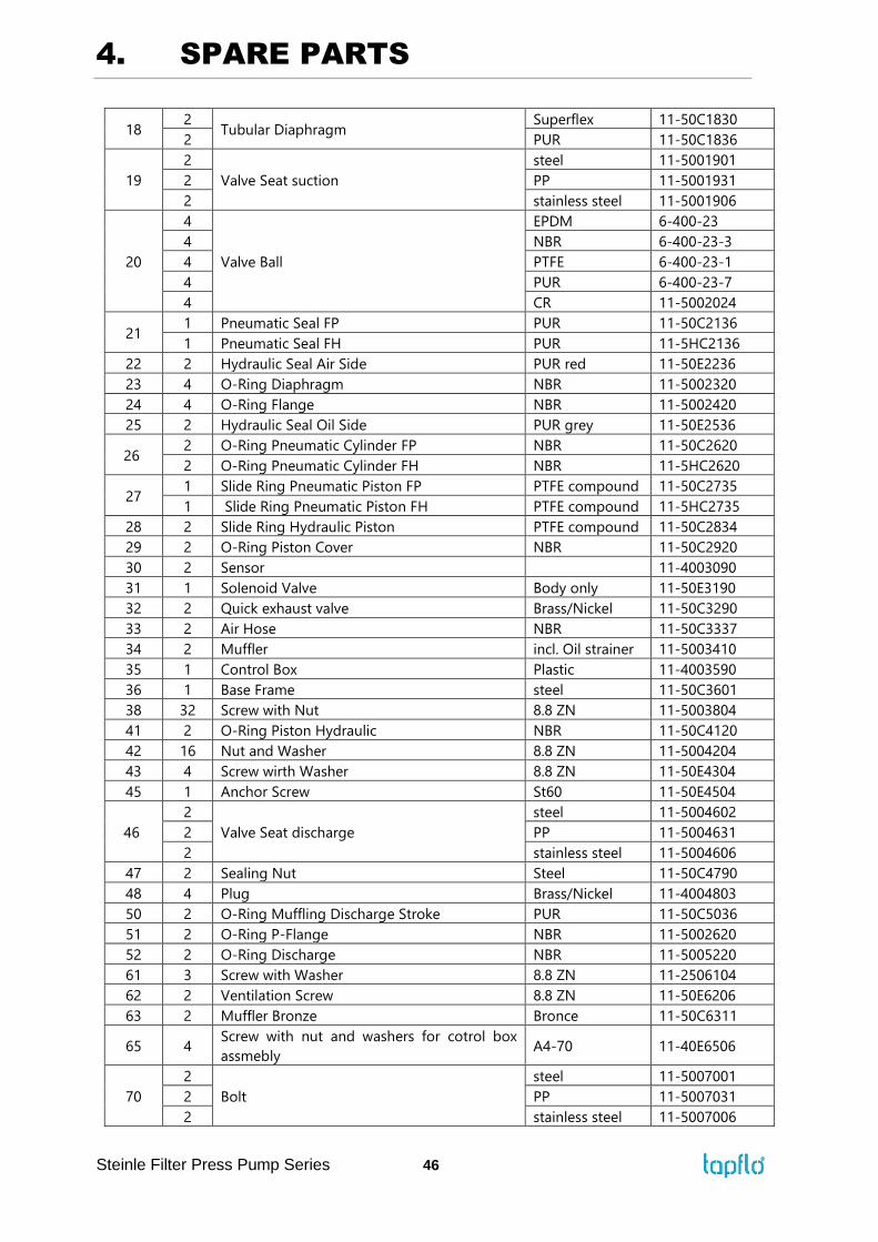
18 2
Tubular Diaphragm Superflex 11-50C1830
2 PUR 11-50C1836
19
2
Valve Seat suction
steel 11-5001901
2 PP 11-5001931
2 stainless steel 11-5001906
20
4
Valve Ball
EPDM 6-400-23
4 NBR 6-400-23-3
4 PTFE 6-400-23-1
4 PUR 6-400-23-7
4 CR 11-5002024
21 1 Pneumatic Seal FP PUR 11-50C2136
1 Pneumatic Seal FH PUR 11-5HC2136
22 2 Hydraulic Seal Air Side PUR red 11-50E2236
23 4 O-Ring Diaphragm NBR 11-5002320
24 4 O-Ring Flange NBR 11-5002420
25 2 Hydraulic Seal Oil Side PUR grey 11-50E2536
26 2 O-Ring Pneumatic Cylinder FP NBR 11-50C2620
2 O-Ring Pneumatic Cylinder FH NBR 11-5HC2620
27 1 Slide Ring Pneumatic Piston FP PTFE compound 11-50C2735
1 Slide Ring Pneumatic Piston FH PTFE compound 11-5HC2735
28 2 Slide Ring Hydraulic Piston PTFE compound 11-50C2834
29 2 O-Ring Piston Cover NBR 11-50C2920
30 2 Sensor 11-4003090
31 1 Solenoid Valve Body only 11-50E3190
32 2 Quick exhaust valve Brass/Nickel 11-50C3290
33 2 Air Hose NBR 11-50C3337
34 2 Muffler incl. Oil strainer 11-5003410
35 1 Control Box Plastic 11-4003590
36 1 Base Frame steel 11-50C3601
38 32 Screw with Nut 8.8 ZN 11-5003804
41 2 O-Ring Piston Hydraulic NBR 11-50C4120
42 16 Nut and Washer 8.8 ZN 11-5004204
43 4 Screw wirth Washer 8.8 ZN 11-50E4304
45 1 Anchor Screw St60 11-50E4504
46
2
Valve Seat discharge
steel 11-5004602
2 PP 11-5004631
2 stainless steel 11-5004606
47 2 Sealing Nut Steel 11-50C4790
48 4 Plug Brass/Nickel 11-4004803
50 2 O-Ring Muffling Discharge Stroke PUR 11-50C5036
51 2 O-Ring P-Flange NBR 11-5002620
52 2 O-Ring Discharge NBR 11-5005220
61 3 Screw with Washer 8.8 ZN 11-2506104
62 2 Ventilation Screw 8.8 ZN 11-50E6206
63 2 Muffler Bronze Bronce 11-50C6311
65 4 Screw with nut and washers for cotrol box
assmebly A4-70 11-40E6506
70
2
Bolt
steel 11-5007001
2 PP 11-5007031
2 stainless steel 11-5007006
4. SPARE PARTS
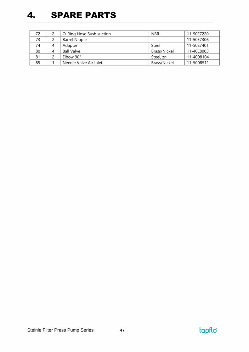
Steinle Filter Press Pump Series 47
72 2 O-Ring Hose Bush suction NBR 11-50E7220
73 2 Barrel Nipple - 11-50E7306
74 4 Adapter Steel 11-50E7401
80 4 Ball Valve Brass/Nickel 11-40E8003
81 2 Elbow 90° Steel, zn 11-4008104
85 1 Needle Valve Air Inlet Brass/Nickel 11-5008511
4. SPARE PARTS
Steinle Filter Press Pump Series 48
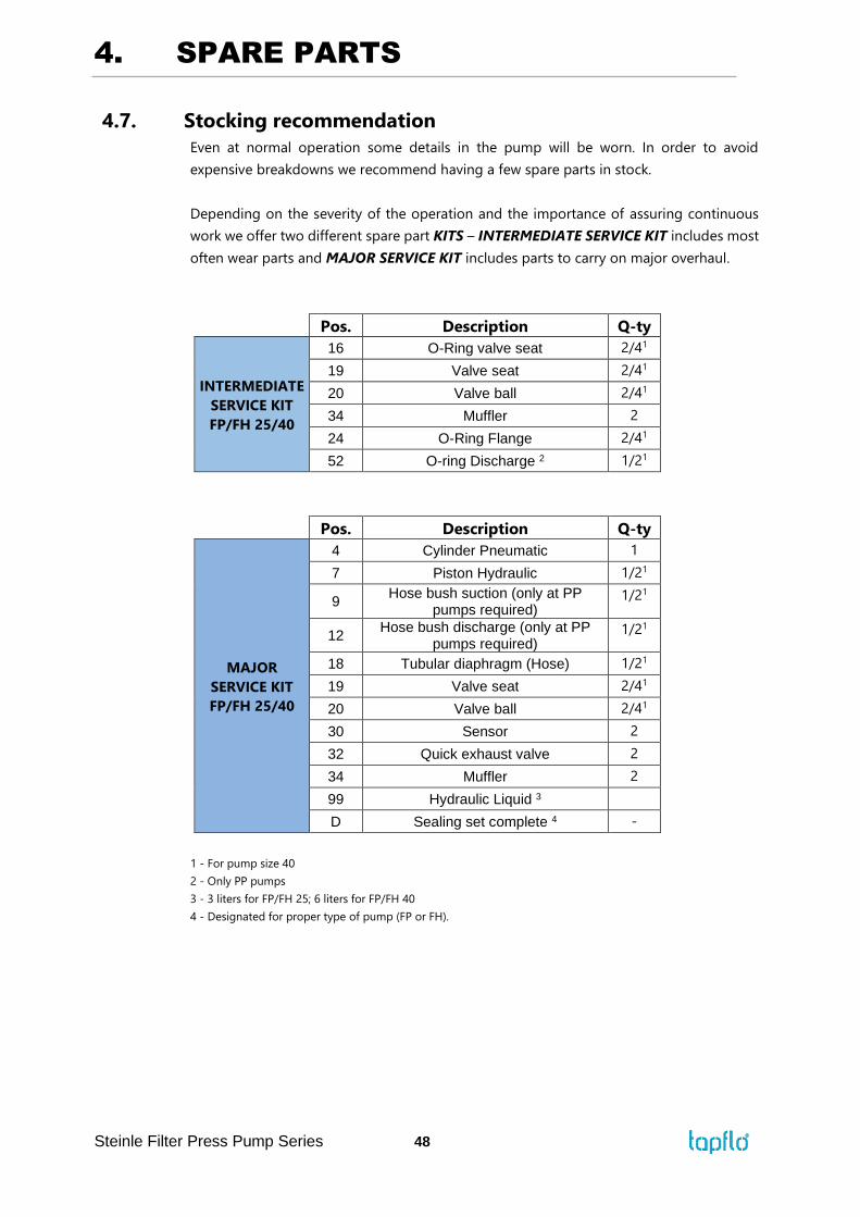
4.7. Stocking recommendation
Even at normal operation some details in the pump will be worn. In order to avoid
expensive breakdowns we recommend having a few spare parts in stock.
Depending on the severity of the operation and the importance of assuring continuous
work we offer two different spare part KITS – INTERMEDIATE SERVICE KIT includes most
often wear parts and MAJOR SERVICE KIT includes parts to carry on major overhaul.
Pos. Description Q-ty
INTERMEDIATE
SERVICE KIT
FP/FH 25/40
16 O-Ring valve seat 2/41
19 Valve seat 2/41
20 Valve ball 2/41
34 Muffler 2
24 O-Ring Flange 2/41
52 O-ring Discharge 2 1/21
Pos. Description Q-ty
MAJOR
SERVICE KIT
FP/FH 25/40
4 Cylinder Pneumatic 1
7 Piston Hydraulic 1/21
9 Hose bush suction (only at PP
pumps required) 1/21
12 Hose bush discharge (only at PP
pumps required) 1/21
18 Tubular diaphragm (Hose) 1/21
19 Valve seat 2/41
20 Valve ball 2/41
30 Sensor 2
32 Quick exhaust valve 2
34 Muffler 2
99 Hydraulic Liquid 3
D Sealing set complete 4 -
1 - For pump size 40
2 - Only PP pumps
3 - 3 liters for FP/FH 25; 6 liters for FP/FH 40
4 - Designated for proper type of pump (FP or FH).
4. SPARE PARTS
Steinle Filter Press Pump Series 49
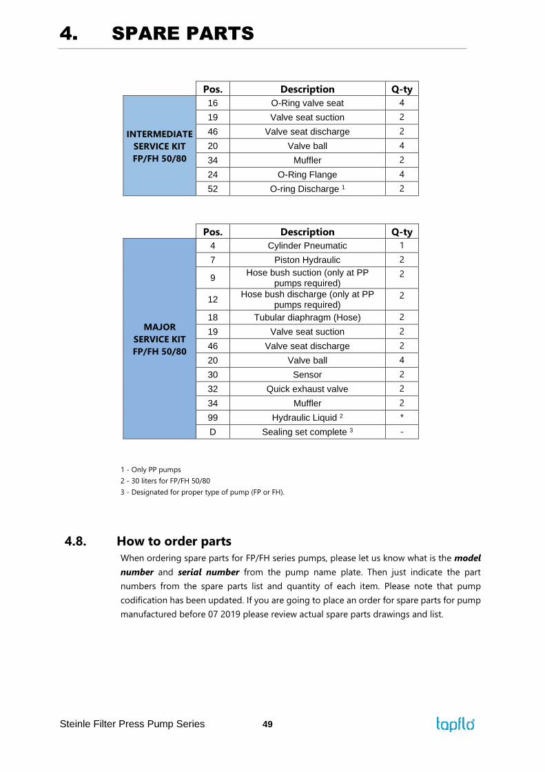
Pos. Description Q-ty
INTERMEDIATE
SERVICE KIT
FP/FH 50/80
16 O-Ring valve seat 4
19 Valve seat suction 2
46 Valve seat discharge 2
20 Valve ball 4
34 Muffler 2
24 O-Ring Flange 4
52 O-ring Discharge 1 2
Pos. Description Q-ty
MAJOR
SERVICE KIT
FP/FH 50/80
4 Cylinder Pneumatic 1
7 Piston Hydraulic 2
9 Hose bush suction (only at PP
pumps required) 2
12 Hose bush discharge (only at PP
pumps required) 2
18 Tubular diaphragm (Hose) 2
19 Valve seat suction 2
46 Valve seat discharge 2
20 Valve ball 4
30 Sensor 2
32 Quick exhaust valve 2
34 Muffler 2
99 Hydraulic Liquid 2 *
D Sealing set complete 3 -
1 - Only PP pumps
2 - 30 liters for FP/FH 50/80
3 - Designated for proper type of pump (FP or FH).
4.8. How to order parts
When ordering spare parts for FP/FH series pumps, please let us know what is the model
number and serial number from the pump name plate. Then just indicate the part
numbers from the spare parts list and quantity of each item. Please note that pump
codification has been updated. If you are going to place an order for spare parts for pump
manufactured before 07 2019 please review actual spare parts drawings and list.

4. SPARE PARTS
Steinle Filter Press Pump Series 50
4.9. Pump code
The model number on the pump and on the front page of this instruction manual tells the
pump size and materials of the pump.
I. FP/FH signature VI. Control voltage
II. Pump standard VII. Diaphragm material
III. Pump size VIII. Valve ball material
IV. Housing material IX. Design series
V. Connetion type
F P 50 C G 1 U U E
I. F = Steinle High Pressure Filterpress pump
II. P = Standard pump - 1:2,4 pressure ratio
H = High pressure pump - 1:3,3 pressure
ratio
III. Pump size
25, 40, 50 or 80
IV. Housing material:
C = Mild steel
S = AISI 316L Stainless steel
P = Polypropylene (PP) (up to max 16 bar)
V. Connetion type:
G = BSP female thread (G 1.1/2" std. on Fx25
and Fx40 metal pumps)
F = Flange acc. to EN 1092-1 Type 11 Face B1
(std. on Fx50, Fx80 and all PP pumps)
A = Flange acc. to ANSI 16.5B Class 150
J = Flange acc. to JIS
VI. Control voltage
1 = 24 VDC (standard)
2 = 220/240 VAC 50 Hz
3 = 110/130 VAC 50/60 Hz
VII. Diaphragm material
S = Superflex (standard)
U = Polyurethane (PU)
VIII. Valve ball material
C = Neoprene (CR) with steel core
E = EPDM
N = NBR
P = Polypropylene (PP)
T = PTFE
U = Polyurethane (PU)
S = AISI 316L Stainless steel
IX. Design series
E = Last standard manufactured at Steinle
F = Current standard - manufactured at
Tapflo

5. DATA
Steinle Filter Press Pump Series 51
5. DATA
5.1. Capacity curves
The performance curves are based on water at 20°C. Other circumstances might change the
performance. See below how the capacity will change at different viscosities and suction lifts.
Example FP 40:
With an existing pressure of 5 bar in compressed air supply, the pump delivers 3,5 m³/h at
approximately 4 bar. Air consumption will be 0,65 m³/min in this case.

5. DATA
Steinle Filter Press Pump Series 52
5.2. Capacity changes
Capacity changes at different suction lifts Capacity changes at different viscosities
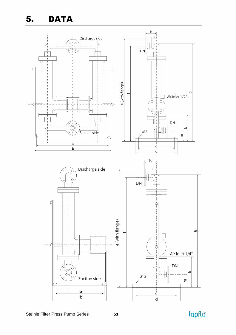
5.3. Dimensions
Dimensions in mm (where other is not indicated)
Dimensions in inch (where other is not indicated)
General dimensions only, ask us for detailed drawings. Changes reserved without notice.
Dimensions Pump size
FP/FH 25 FP/FH 40 FP/FH 50 FP/FH 80
a 687 / 27,05 950 / 37,40 1423 / 56,02 1423 / 56,02
b 747 / 29,41 1010 / 39,76 1483 / 58,39 1483 / 58,39
c 380 / 14,96 380 / 14,96 480 / 18,90 480 / 18,90
d 440 / 17,32 440 / 17,32 540 / 21,26 540 / 21,26
e 1225 / 48,23 1225 / 48,23 1760 / 69,29 1810 / 71,26
f 1150 / 45,28 1150 / 45,28 1660 / 65,35 1710 / 67,32
g 1170 / 46,06 1170 / 46,06 1700 / 66,93 1750 / 68,90
h 120 / 4,72 120 / 4,72 130 / 5,12 130 / 5,12
i 50 / 1,97 50 / 1,97 60 / 2,36 60 / 2,36
k 300 / 11,81 300 / 11,81 300 / 11,81 300 / 11,81
m 120 / 4,72 120 / 4,72 240 / 9,45 240 / 9,45
DN 40 / 1,57 40 / 1,57 50 / 1,97 80 / 3,15
5. DATA
Steinle Filter Press Pump Series 53
5. DATA
Steinle Filter Press Pump Series 54
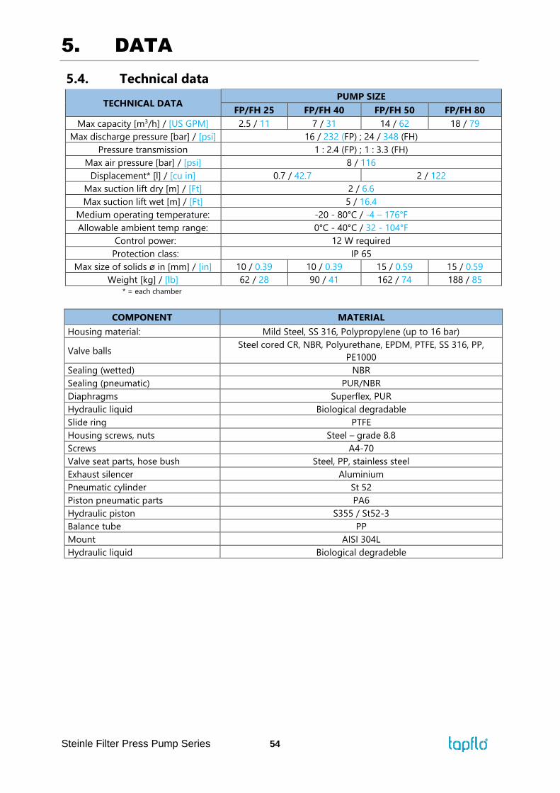
5.4. Technical data
TECHNICAL DATA PUMP SIZE
FP/FH 25 FP/FH 40 FP/FH 50 FP/FH 80
Max capacity [m3/h] / [US GPM] 2.5 / 11 7 / 31 14 / 62 18 / 79
Max discharge pressure [bar] / [psi] 16 / 232 (FP) ; 24 / 348 (FH)
Pressure transmission 1 : 2.4 (FP) ; 1 : 3.3 (FH)
Max air pressure [bar] / [psi] 8 / 116
Displacement* [l] / [cu in] 0.7 / 42.7 2 / 122
Max suction lift dry [m] / [Ft] 2 / 6.6
Max suction lift wet [m] / [Ft] 5 / 16.4
Medium operating temperature: -20 - 0°C / -4 – 176°F
Allowable ambient temp range: 0°C - 40°C / 32 - 104°F
Control power: 12 W required
Protection class: IP 65
Max size of solids ø in [mm] / [in] 10 / 0.39 10 / 0.39 15 / 0.59 15 / 0.59
Weight [kg] / [lb] 62 / 28 90 / 41 162 / 74 188 / 85
* = each chamber
COMPONENT MATERIAL
Housing material: Mild Steel, SS 316, Polypropylene (up to 16 bar)
Valve balls Steel cored CR, NBR, Polyurethane, EPDM, PTFE, SS 316, PP,
PE1000
Sealing (wetted) NBR
Sealing (pneumatic) PUR/NBR
Diaphragms Superflex, PUR
Hydraulic liquid Biological degradable
Slide ring PTFE
Housing screws, nuts Steel – grade 8.8
Screws A4-70
Valve seat parts, hose bush Steel, PP, stainless steel
Exhaust silencer Aluminium
Pneumatic cylinder St 52
Piston pneumatic parts PA6
Hydraulic piston S355 / St52-3
Balance tube PP
Mount AISI 304L
Hydraulic liquid Biological degradeble
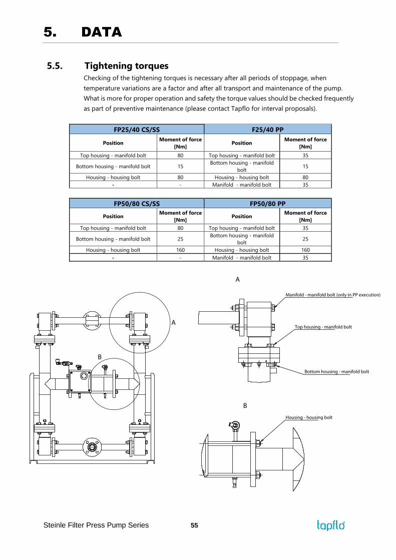
5. DATA
Steinle Filter Press Pump Series 55
5.5. Tightening torques
Checking of the tightening torques is necessary after all periods of stoppage, when
temperature variations are a factor and after all transport and maintenance of the pump.
What is more for proper operation and safety the torque values should be checked frequently
as part of preventive maintenance (please contact Tapflo for interval proposals).
FP25/40 CS/SS F25/40 PP
Position Moment of force
[Nm] Position
Moment of force
[Nm]
Top housing - manifold bolt 80 Top housing - manifold bolt 35
Bottom housing - manifold bolt 15 Bottom housing - manifold
bolt 15
Housing - housing bolt 80 Housing - housing bolt 80
- - Manifold - manifold bolt 35
FP50/80 CS/SS FP50/80 PP
Position Moment of force
[Nm] Position
Moment of force
[Nm]
Top housing - manifold bolt 80 Top housing - manifold bolt 35
Bottom housing - manifold bolt 25 Bottom housing - manifold
bolt 25
Housing - housing bolt 160 Housing - housing bolt 160
- - Manifold - manifold bolt 35
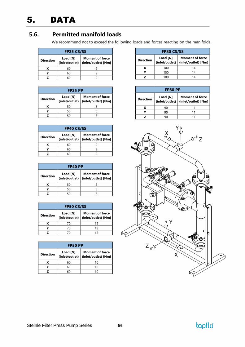
5. DATA
Steinle Filter Press Pump Series 56
5.6. Permitted manifold loads
We recommend not to exceed the following loads and forces reacting on the manifolds.
FP25 CS/SS
Direction Load [N]
(inlet/outlet)
Moment of force
(inlet/outlet) [Nm]
X 60 9
Y 60 9
Z 60 9
FP25 PP
Direction Load [N]
(inlet/outlet)
Moment of force
(inlet/outlet) [Nm]
X 50 8
Y 50 8
Z 50 8
FP40 CS/SS
Direction Load [N]
(inlet/outlet)
Moment of force
(inlet/outlet) [Nm]
X 60 9
Y 60 9
Z 60 9
FP40 PP
Direction Load [N]
(inlet/outlet)
Moment of force
(inlet/outlet) [Nm]
X 50 8
Y 50 8
Z 50 8
FP50 CS/SS
Direction Load [N]
(inlet/outlet)
Moment of force
(inlet/outlet) [Nm]
X 70 12
Y 70 12
Z 70 12
FP50 PP
Direction Load [N]
(inlet/outlet)
Moment of force
(inlet/outlet) [Nm]
X 60 10
Y 60 10
Z 60 10
FP80 CS/SS
Direction Load [N]
(inlet/outlet)
Moment of force
(inlet/outlet) [Nm]
X 100 14
Y 100 14
Z 100 14
FP80 PP
Direction Load [N]
(inlet/outlet)
Moment of force
(inlet/outlet) [Nm]
X 90 11
Y 90 11
Z 90 11
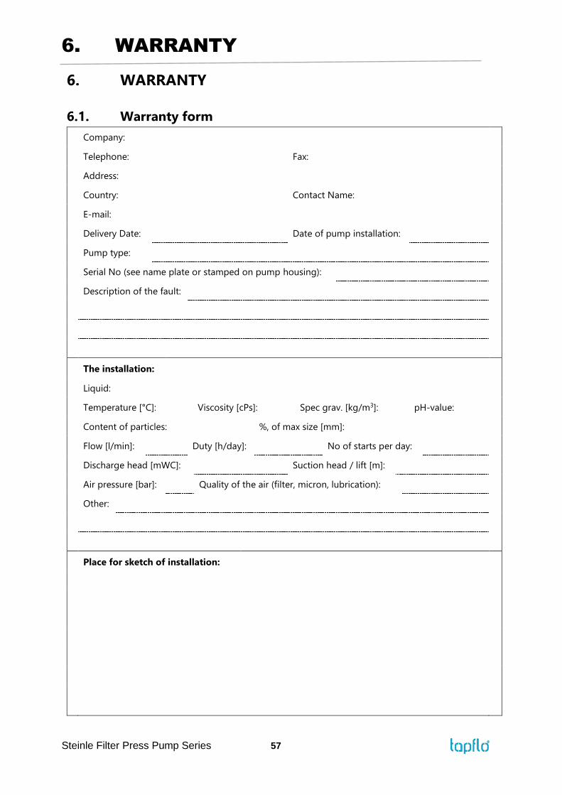
6. WARRANTY
Steinle Filter Press Pump Series 57
6. WARRANTY
6.1. Warranty form
Company:
Telephone: Fax:
Address:
Country: Contact Name:
E-mail:
Delivery Date: Date of pump installation:
Pump type:
Serial No (see name plate or stamped on pump housing):
Description of the fault:
The installation:
Liquid:
Temperature [°C]: Viscosity [cPs]: Spec grav. [kg/m3]: pH-value:
Content of particles: %, of max size [mm]:
Flow [l/min]: Duty [h/day]: No of starts per day:
Discharge head [mWC]: Suction head / lift [m]:
Air pressure [bar]: Quality of the air (filter, micron, lubrication):
Other:
Place for sketch of installation:
7. WARRANTY
Steinle Filter Press Pump Series 58
6.2. Returning parts
When returning parts to Tapflo please follow this procedure:
➢ Consult Tapflo for shipping instructions.
➢ Cleanse or neutralize and rinse the part/pump. Make sure the part/pump is
completely empty from liquid.
➢ Pack the return articles carefully to prevent any damage during transportation.
Goods will not be accepted unless the above procedure has been complied with.
6.3. Warranty
Tapflo warrants products under conditions as stated below for a period of not more than 5
years from installation and not more than 6 years from date of manufacturing.
1. The following terms and conditions apply to the sale of machinery, components and
related services and products, of Tapflo (hereinafter “the products”).
2. Tapflo (the manufacturer) warrants that:
a. its products are free of defects in material, design and workmanship at the time of
original purchase;
b. its products will function in accordance with Tapflo operative manuals; Tapflo does
not guarantee that the product will meet the precise needs of the Customer, except
for those purposes set out in any invitation to render documents or other documents
specifically made available to Tapflo before entering into this agreement;
c. high quality materials are used in the construction of the pumps and that machining
and assembly are carried out to the highest standards.
Except as expressly stated above, Tapflo makes no warranties, express or implied,
concerning the products, including all warranties of fitness for a particular purpose.
3. This warranty shall not be applicable in circumstances other than defects in material,
design, and workmanship. In particular warranty shall not cover the following:
a. Periodic checks, maintenance, repair and replacement of parts due to normal wear
and tear (seals, O-rings, rubber items, diaphragms, air valves etc..);
b. Damage to the product resulting from:
b.1. Tampering with, abuse or misuse, including but not limited to failure to use the
product for its normal purposes as stated at the time of purchase or in accordance
with Tapflo instructions for use and maintenance of the product, or the
installation or improper ventilation or use of the product in a manner inconsistent
with the technical or safety standard in force;
b.2. Repairs performed by non-skilled personnel or use of non-original Tapflo parts;

7. WARRANTY
Steinle Filter Press Pump Series 59
b.3. Accidents or any cause beyond the control of Tapflo, including but not limited
to lightning, water, fire, earthquake, and public disturbances, etc.;
4. The warrantee shall cover the replacement or repairing of any parts, which is documented
faulty due to construction or assembling, with new or repaired parts free of charges
delivered by Tapflo. Parts subjected to normal tear and wear shall not be covered by the
warranty. Tapflo shall decide as to whether the defective or faulty part shall be replaced
or repaired.
5. The warrantee of the products shall be valid for a period in accordance to the current law
from the date of delivery, under the condition that notice of the alleged defect to the
products or parts thereof be given to Tapflo in written within the mandatory term of 8
days from the discovery. Repair or replacement under the terms of this warranty shall not
give a right to an extension to, or a new commencement of, the period of warranty.
6. Repair or replacement under the terms of this warranty shall not give a right to an
extension to, or a new commencement of, the period of warranty. Repair or replacement
under the terms of this warranty may be fulfilled with functionally equivalent
reconditioned units. Tapflo qualified personnel shall be solely entitled to carry out repair
or replacement of faulty parts after careful examination of the pump. Replaced faulty parts
or components will become the property of Tapflo.
7. The products are built in accordance with standard CE normative and are tested (where
applicable) by Tapflo. Approval and tests by other control authority are for the customer’s
account. The products shall not be considered defective in materials, design or
workmanship if they need to be adapted, changed or adjusted to conform to national or
local technical or safety standards in force in any country other than that for which the
unit was originally designed and manufactured. This warranty shall not reimburse such
adaptations, changes or adjustments, or attempt to do so, whether properly performed
or not, nor any damage resulting from them, nor any adaptation, change or adjustments
to upgrade the products from their normal purpose as described in the products operative
manual without the prior written consent of Tapflo.
8. Installation, including electric and other connections to utility mains according to Tapflo
drawings, is for the cost and responsibility of the customer, unless otherwise agreed in
writing.
9. Tapflo will not be liable on any claim, whether in contact, tort, or otherwise, for any
indirect, special, incidental, or consequential damages, caused to the customer or to third
parties, including loss of profits, arising by any possible infringement of par. 3 above or
by the customer or third parties being in the impossibility of using the products.
Steady the above, Tapflo liability to the customer or third parties from any claim, whether in
contract, tort, or otherwise, shall be limited to the total amount paid by the customer for the
product that caused the damages.
