steering stc a - my4dsc.com service manua… · • after engine start, the hydraulic pump electric...
TRANSCRIPT
STEERING
C
D
E
SECTION STC A
B
STEERING CONTROL SYSTEM
F
H
I
J
K
L
M
TC
N
O
P
CONTENTS
S
PRECAUTION ............................................... 3
PRECAUTIONS ................................................... 3Precaution for Supplemental Restraint System (SRS) "AIR BAG" and "SEAT BELT PRE-TEN-SIONER" ...................................................................3Service Notice and Precautions for Hydraulic Pump Electric Power Steering System .....................3
SYSTEM DESCRIPTION .............................. 4
COMPONENT PARTS ........................................ 4Component Parts Location ........................................4Power Steering Oil Pump Assembly .........................5
SYSTEM .............................................................. 6
HYDRAULIC PUMP ELECTRIC POWER STEER-ING SYSTEM ...............................................................6
HYDRAULIC PUMP ELECTRIC POWER STEERING SYSTEM : System Description ..............6HYDRAULIC PUMP ELECTRIC POWER STEERING SYSTEM : Fail-safe ...............................8HYDRAULIC PUMP ELECTRIC POWER STEERING SYSTEM : Protection Function ..............9
DIAGNOSIS SYSTEM (POWER STEERING CONTROL MODULE) ........................................10
CONSULT Function ................................................10
ECU DIAGNOSIS INFORMATION ..............11
POWER STEERING CONTROL MODULE ........11Reference Value .....................................................11Fail-safe ..................................................................12Protection Function .................................................12DTC Inspection Priority Chart .................................13DTC Index ...............................................................13
WIRING DIAGRAM ......................................14
HYDRAULIC PUMP ELECTRIC POWER STEERING SYSTEM .........................................14
Wiring Diagram ........................................................14
BASIC INSPECTION ...................................17
DIAGNOSIS AND REPAIR WORK FLOW .......17Work Flow ................................................................17Diagnostic Work Sheet ............................................18
DTC/CIRCUIT DIAGNOSIS .........................20
C1143 STEERING ANGLE SENSOR ...............20DTC Logic ................................................................20Diagnosis Procedure ...............................................20
C1601 BATTERY POWER SUPPLY ................21DTC Logic ................................................................21Diagnosis Procedure ...............................................21
C1602 NO TUNING SET ...................................24DTC Logic ................................................................24Diagnosis Procedure ...............................................24
C1606 EPS MOTOR ..........................................25DTC Logic ................................................................25Diagnosis Procedure ...............................................25
C1607, C1608 POWER STEERING CON-TROL MODULE ................................................26
DTC Logic ................................................................26Diagnosis Procedure ...............................................26
C1609 VEHICLE SPEED SIGNAL ....................27DTC Logic ................................................................27Diagnosis Procedure ...............................................27
C160A HEAT PROTECTION ............................29DTC Logic ................................................................29
U1000 CAN COMM CIRCUIT ...........................30Description ...............................................................30DTC Logic ................................................................30
STC-1Revision: October 2015 2016 Maxima NAM

Diagnosis Procedure .............................................. 30
HYDRAULIC PUMP ELECTRIC POWER STEERING WARNING LAMP ........................... 31
Component Function Check ................................... 31Diagnosis Procedure .............................................. 31
SYMPTOM DIAGNOSIS ............................. 32
HYDRAULIC PUMP ELECTRIC POWER STEERING WARNING LAMP DOES NOT TURN ON ........................................................... 32
Description .............................................................. 32Diagnosis Procedure .............................................. 32
HYDRAULIC PUMP ELECTRIC POWER STEERING WARNING LAMP DOES NOT TURN OFF ......................................................... 33
Description .............................................................. 33
Diagnosis Procedure ............................................... 33
STEERING WHEEL TURNING FORCE IS HEAVY OR LIGHT ............................................. 34
Diagnosis Procedure ............................................... 34
UNBALANCE STEERING WHEEL TURNING FORCE AND RETURN BETWEEN RIGHT AND LEFT ......................................................... 36
Diagnosis Procedure ............................................... 36
UNBALANCE STEERING WHEEL TURNING FORCE (TORQUE VARIATION) ....................... 37
Diagnosis Procedure ............................................... 37
REMOVAL AND INSTALLATION .............. 39
POWER STEERING CONTROL MODULE ....... 39Removal and Installation ......................................... 39
STC-2Revision: October 2015 2016 Maxima NAM

PRECAUTIONS
C
D
E
F
H
I
J
K
L
M
A
B
TC
N
O
P
< PRECAUTION >
S
PRECAUTIONPRECAUTIONSPrecaution for Supplemental Restraint System (SRS) "AIR BAG" and "SEAT BELT PRE-TENSIONER" INFOID:0000000012188133
The Supplemental Restraint System such as “AIR BAG” and “SEAT BELT PRE-TENSIONER”, used alongwith a front seat belt, helps to reduce the risk or severity of injury to the driver and front passenger for certaintypes of collision. Information necessary to service the system safely is included in the SR and SB section ofthis Service Manual.WARNING:• To avoid rendering the SRS inoperative, which could increase the risk of personal injury or death in
the event of a collision which would result in air bag inflation, all maintenance must be performed byan authorized NISSAN/INFINITI dealer.
• Improper maintenance, including incorrect removal and installation of the SRS, can lead to personalinjury caused by unintentional activation of the system. For removal of Spiral Cable and Air BagModule, see the SR section.
• Do not use electrical test equipment on any circuit related to the SRS unless instructed to in thisService Manual. SRS wiring harnesses can be identified by yellow and/or orange harnesses or har-ness connectors.
PRECAUTIONS WHEN USING POWER TOOLS (AIR OR ELECTRIC) AND HAMMERSWARNING:• When working near the Airbag Diagnosis Sensor Unit or other Airbag System sensors with the Igni-
tion ON or engine running, DO NOT use air or electric power tools or strike near the sensor(s) with ahammer. Heavy vibration could activate the sensor(s) and deploy the air bag(s), possibly causingserious injury.
• When using air or electric power tools or hammers, always switch the Ignition OFF, disconnect thebattery and wait at least three minutes before performing any service.
Service Notice and Precautions for Hydraulic Pump Electric Power Steering SystemINFOID:0000000012188134
• Check each tire for proper air pressure and size. Refer to MA-36, "WHEELS : Inspection".• Verify that the steering system components are genuine NISSAN parts and have been installed properly.• Check the steering column for loose attaching bolts.• Check the steering gear for loose attaching bolts. Check the inner sockets and outer sockets for damage or
wear. Inspect the boots and seals for leakage of power steering fluid.• Verify proper wheel alignment. Refer to FSU-23, "Wheel Alignment (Unladen*)".• Check for any damage, wear, or modification to the suspension and body that would result in increased
weight or an improper wheelarch height. Refer to FSU-24, "Wheelarch Height (Unladen*1)".• Check for proper battery voltage.• Verify that all power steering pump connections are clean and fully seated.• Verify that only genuine NISSAN E-PSF is used. Use of any power steering fluid other than genuine NISSAN
E-PSF will prevent the power steering system from proper operation.• An audible high pitch noise may be heard from the engine compartment when the steering wheel is oper-
ated, particularly at low speeds such as a parking lot maneuver. This condition is not a malfunction, rathernormal system operation. Steering at low speeds or parking lot maneuvers demands higher hydraulic assis-tance, resulting in larger power steering pump load and increased system noise.
• The power steering pump is electrically controlled by the power steering control module.• Before connecting or disconnecting the power steering control module harness connectors, turn ignition
switch “OFF” and disconnect battery ground cable. Battery voltage is applied to power steering control mod-ule even if ignition switch is turned “OFF”.
STC-3Revision: October 2015 2016 Maxima NAM

COMPONENT PARTS
< SYSTEM DESCRIPTION >SYSTEM DESCRIPTIONCOMPONENT PARTSComponent Parts Location INFOID:0000000012188135
A. Engine room right side
ALGIA0239ZZ
No. Component Function
1. IPDM E/R
Transmits mainly the following signal to power steering control module via CAN communication:• Engine status signal- Refer to PCS-5, "Component Parts Location" for detailed instal-
lation location.
2. Combination meter
Transmits mainly the following signal to power steering control module via CAN communication:• Vehicle speed signal- Refer to PCS-5, "Component Parts Location" for detailed instal-
lation location.
The hydraulic pump electric power steering system warning lamp turns ON according to the signal received by CAN communication from the power steering control module.
3. Steering angle sensor
Transmits mainly the following signal to power steering control module via CAN communication:• Steering angle sensor signal- Refer to PCS-5, "Component Parts Location" for detailed instal-
lation location.
STC-4Revision: October 2015 2016 Maxima NAM

COMPONENT PARTS
C
D
E
F
H
I
J
K
L
M
A
B
TC
N
O
P
< SYSTEM DESCRIPTION >
S
Power Steering Oil Pump Assembly INFOID:0000000012188136
The power steering oil pump assembly is primarily composed of thereservoir tank (1), power steering oil pump (2), power steering motor(3), and power steering control module (4).
RESERVOIR TANKFluid is filled from the reservoir tank.
POWER STEERING OIL PUMPThe power steering oil pump is driven by the power steering motor and generates hydraulic oil pressure in thesystem.
POWER STEERING MOTORThe power steering motor is controlled by the power steering control module and drives the power steering oilpump.
POWER STEERING CONTROL MODULEBy receiving steering angle sensor signal and vehicle speed signal, the power steering control module calcu-lates hydraulic pressure of the hydraulic pump electric power steering system according to the driving condi-tions. The power steering control module controls the power steering motor.
4. Power steering oil pump assembly
Reservoir tank
STC-5, "Power Steering Oil Pump Assembly"Power steering oil pump
Power steering motor
Power steering control module
No. Component Function
JSGIA0914ZZ
STC-5Revision: October 2015 2016 Maxima NAM

SYSTEM
< SYSTEM DESCRIPTION >SYSTEMHYDRAULIC PUMP ELECTRIC POWER STEERING SYSTEMHYDRAULIC PUMP ELECTRIC POWER STEERING SYSTEM : System DescriptionINFOID:0000000012188137
• The system is composed primarily of the power steering oil pump assembly (power steering control module,power steering motor, power steering oil pump, and reservoir tank), hydraulic pipes, and steering gearassembly.
• The power steering control module controls the speed of the power steering motor according to the vehiclespeed and steering angle speed. By changing the power steering oil pump flow, the power steering controlmodule controls the steering assist force.
• According to the power steering motor control, the system hydraulic pressure is transmitted from the powersteering motor to the power steering oil pump. The power steering oil pump is driven by the system hydraulicpressure.
• After engine start, the hydraulic pump electric power steering system performs control.• When a malfunction occurs in the system, the fail-safe function stops the hydraulic pump electric power
steering system (manual steering state) or restricts its operation (certain steering assist force). Refer to STC-8, "HYDRAULIC PUMP ELECTRIC POWER STEERING SYSTEM : Fail-safe".
• When the power steering function is used continuously in an extreme manner, the protective functionreduces the output to the power steering motor. Refer to STC-9, "HYDRAULIC PUMP ELECTRIC POWERSTEERING SYSTEM : Protection Function".
SYSTEM DIAGRAM
INPUT/OUTPUT SIGNALCommunicates the signal from each control unit via CAN communication.
OPERATION CHARACTERISTICS
JSGIA0915GB
Control unit Signal status
ECMTransmits mainly the following signal to power steering control module via CAN communi-cation:• Engine status signal
Steering angle sensorTransmits mainly the following signal to power steering control module via CAN communi-cation:• Steering angle sensor signal
Combination meter
Transmits mainly the following signal to power steering control module via CAN communi-cation:• Vehicle speed signalReceives mainly the following signal from power steering control module via CAN commu-nication:• Hydraulic pump electric power steering warning lamp signal
STC-6Revision: October 2015 2016 Maxima NAM

SYSTEM
C
D
E
F
H
I
J
K
L
M
A
B
TC
N
O
P
< SYSTEM DESCRIPTION >
S
When the steering angle speed is high or the vehicle speed is low,force is generated by increasing discharge amount from the powersteering oil pump and by raising system hydraulic pressure.
OPERATION PRINCIPLEWhen Steering Wheel is in the Neutral Position
Because the hydraulic routes open at the power steering pump, right side of gear housing, left side of gearhousing, and reservoir tank, the hydraulic pressure applied to the right side and left side of the gear housing isequal and no steering assist force is generated. When Steering Wheel is Rotated to the Right
The hydraulic routes open from power steering pump to right side of gear housing and from left side of gearhousing to reservoir tank, providing left directional assist force to the rack.
JSGIA0916GB
JSGIA0918GB
JSGIA0919GB
STC-7Revision: October 2015 2016 Maxima NAM

SYSTEM
< SYSTEM DESCRIPTION >When Steering Wheel is Rotated to the LeftThe hydraulic routes open from power steering pump to left side of the gear housing and from the right side ofthe gear housing to reservoir tank, providing right directional assist force to the rack.
CONDITIONS FOR HYDRAULIC PUMP ELECTRIC POWER STEERING WARNING LAMP ON• When the hydraulic pump electric power steering system is operating and steering assist force is being gen-
erated, the hydraulic pump electric power steering warning lamp is OFF.• When the hydraulic pump electric power steering system is stopped by the fail-safe or protective function
and steering assist force is not being generated, the hydraulic pump electric power steering warning lampturns ON to inform the driver that the system is in the manual steering state.NOTE:When the hydraulic pump electric power steering system turns ON according to the protection system, thecause is internal high temperature state of the hydraulic pump electric power steering system. By stoppingthe engine, internal temperature of the system decreases. After starting the engine, the system returns to thenormal state and the hydraulic pump electric power steering system warning lamp turns OFF. (The system isnot malfunctioning.) For information about the protective function, refer to STC-9, "HYDRAULIC PUMPELECTRIC POWER STEERING SYSTEM : Protection Function".
• When the ignition switch is turned ON, this lamp turns ON for lamp check (system check). When the systemis operating normally, the lamp turns OFF after the engine starts.
HYDRAULIC PUMP ELECTRIC POWER STEERING SYSTEM : Fail-safe INFOID:0000000012188138
When an error occurs in the hydraulic pump electric power steering system, fail-safe brings the system to ahalt (manual steering) or restricted (constant steering assist level) state. When the system is in a halt state,fail-safe turns ON the hydraulic pump electric power steering warning lamp to warn the driver that the hydrau-lic pump electric power steering system is in the manual steering state.
JSGIA0917GB
Condition Hydraulic pump electric power steering warning lamp
Ignition switch ON (lamp check) ON
After engine start (Steering assist force is generated.) OFF
When steering assist is stopped ON
DTC Fail-safe condition
C1143 Certain steering assist force
C1601 Manual steering state
C1602 Certain steering assist force
C1606 Manual steering state
C1607 Certain steering assist force
C1608 Manual steering state
STC-8Revision: October 2015 2016 Maxima NAM

SYSTEM
C
D
E
F
H
I
J
K
L
M
A
B
TC
N
O
P
< SYSTEM DESCRIPTION >
S
HYDRAULIC PUMP ELECTRIC POWER STEERING SYSTEM : Protection FunctionINFOID:0000000012188139
• When the steering wheel is operated repeatedly or turned all the way for a long period during parking or low-speed driving, the function of the hydraulic pump electric power steering system becomes limited to preventthe system from overheating. If the steering wheel is operated furthermore, the hydraulic pump electricpower steering system stops and the hydraulic pump electric power steering system warning lamp may beturned ON. In this case, the steering wheel operation temporarily becomes difficult. This is not a malfunction.When the engine is turned OFF (ignition switch OFF) and steering operation is stopped for a while, the tem-perature of the hydraulic pump electric power steering system decreases and the steering operation returnsto normal after restarting the engine.
• Then, the hydraulic pump electric power steering system warning lamp turns OFF. If the system is OFFunder the protection state, the hydraulic pump electric power steering system warning lamp turns ON towarn that the system is in the manual steering state. This is not a system malfunction. In addition, the follow-ing DTC remains to distinguish from a malfunction:
C1609 Certain steering assist force
U1000Normal controlNOTE:If the cause is in a different ECU, the state changes to fixed steering assist force.
DTC Fail-safe condition
DTC Vehicle condition
C160A The system temporarily enters the manual steering state. (This is not a hydraulic pump electric power steering system malfunction.)
STC-9Revision: October 2015 2016 Maxima NAM

DIAGNOSIS SYSTEM (POWER STEERING CONTROL MODULE)
< SYSTEM DESCRIPTION >DIAGNOSIS SYSTEM (POWER STEERING CONTROL MODULE)CONSULT Function INFOID:0000000012188140CAUTION:After disconnecting the CONSULT vehicle interface (VI) from the data link connector, the ignition mustbe cycled OFF → ON (for at least 5 seconds) → OFF. If this step is not performed, the BCM may not goto "sleep mode", potentially causing a discharged battery and a no-start condition.
FUNCTIONCONSULT can display each diagnostic item using the diagnostic test modes shown as per the following:
ECU IDENTIFICATIONDisplays the part number stored in the control unit.
SELF DIAGNOSTIC RESULT MODERefer to STC-13, "DTC Index".
When “CRNT” is displayed on self-diagnosis result• The system is presently malfunctioning.
When “PAST” is displayed on self-diagnosis result• System malfunction from the past is detected, but the system is presently normal.
DATA MONITOR MODE
Diagnostic test mode Function
ECU Identification The part number stored in the control unit can be read.
Self Diagnostic Result Self diagnostic results and freeze frame data can be read and erased quickly.
Data Monitor Input/Output data in the power steering control module can be read.
Monitor item (Unit) Remarks
BATTERY VOLT (V) Displays the power supply voltage for power steering control module.
STEERING ANGLE Displays the steering angle based on the steering angle signal transmitted by CAN com-munication.
STR ANG SPD (deg/s) Displays the steering angle speed based on the steering angle signal transmitted by CAN communication.
MOTOR CURRENT (A) Displays the current value consumed by power steering control module.
MTR REV SPD COMM (rpm) Displays the power steering motor speed command value.
MTR REV SPD (rpm) Displays the power steering motor speed.
C/U TEMP (°C or °F) Displays the temperature of the power steering control module.
C/U TEMP A (°C or °F) Displays the temperature of the power steering control module.
MTR ASSIST (%) Displays the current percentage of the allowable assist ratio power steering motor.
ESTM VHCL SPD (km/h or mph) Displays the vehicle speed calculated by the power steering control module.
WARNING LAMP (On/Off) Hydraulic pump electric power steering system warning lamp control status is displayed.
ENGINE STATUS (STOP/RUN/CRANK) Engine speed is displayed from engine condition signal with CAN communication.
VHCL SPD JUDGE (OK/NG) Displays the receiving status of the vehicle speed signal transmitted by CAN communi-cation.
STC-10Revision: October 2015 2016 Maxima NAM

POWER STEERING CONTROL MODULE
C
D
E
F
H
I
J
K
L
M
A
B
TC
N
O
P
< ECU DIAGNOSIS INFORMATION >
S
ECU DIAGNOSIS INFORMATIONPOWER STEERING CONTROL MODULEReference Value INFOID:0000000012188141
VALUES ON THE DIAGNOSIS TOOL
*1: The value changes according to load of power steering motor.*2: This is in close agreement with a motor speed command value. Although a quick steering operation maycause disagreement, this is not a malfunction.*3: Usually, 100% is displayed. An excessive steering operation gradually lowers the percentage. When leftstanding, the percentage returns to 100%.*4: This may not agree with the speedometer indication immediately after the ignition switch is turned ON. Thisis not a malfunction.
Monitor item Data monitor
Condition Display value
BATTERY VOLT Engine running Battery voltage (V)
STEERING ANGLEThe steering wheel is not steered. Approx. 0.0 deg
The steering wheel is steered. Displays steering angle (deg)
STR ANG SPDThe steering wheel is not steered. Approx. 0.0 deg/s
The steering wheel is steered. Displays steering angle speed (deg/s)
MOTOR CURRENT Engine running
Steering wheel: Not steering (There is no steering force.) MAX approx. 10 A*1
Steering wheel: Right or left turn Displays consumption current of pow-er steering control module (A)
MTR REV SPD COMM Engine running
Steering wheel: Not steering (There is no steering force.)
Shows an almost constant value (rpm)
Steering wheel: Right or left turn The value changes as a steering speed (rpm)
MTR REV SPD Engine running
Steering wheel: Not steering (There is no steering force.)
Shows an almost constant value (rpm)*2
Steering wheel: Right or left turnThe value changes as a steering speed (rpm)*2
C/U TEMP Engine running Displays temperature of inside power steering control module (°C or °F)
C/U TEMP A Engine running Displays temperature of inside power steering control module (°C or °F)
MTR ASSIST Engine running 100%*3
ESTM VHCL SPD
Vehicle stopped 0.00 km/h or mph
While drivingApproximately equal to the indication on speedometer*4(inside of ±10%)
WARNING LAMPHydraulic pump electric power steering warning lamp: ON On
Hydraulic pump electric power steering warning lamp: OFF Off
ENGINE STATUS
Engine not running STOP
Engine running RUN
Engine cranking CRANK
VHCL SPD JUDGEVehicle speed signal can be received via CAN communication. OK
Vehicle speed signal cannot be received via CAN communica-tion. NG
STC-11Revision: October 2015 2016 Maxima NAM

POWER STEERING CONTROL MODULE
< ECU DIAGNOSIS INFORMATION >TERMINAL LAYOUTPHYSICAL VALUES
Fail-safe INFOID:0000000012188142
When an error occurs in the hydraulic pump electric power steering system, fail-safe brings the system to ahalt (manual steering) or restricted (constant steering assist level) state. When the system is in a halt state,fail-safe turns ON the hydraulic pump electric power steering warning lamp to warn the driver that the hydrau-lic pump electric power steering system is in the manual steering state.
Protection Function INFOID:0000000012188143
• When the steering wheel is operated repeatedly or turned all the way for a long period during parking or low-speed driving, the function of the hydraulic pump electric power steering system becomes limited to preventthe system from overheating. If the steering wheel is operated furthermore, the hydraulic pump electricpower steering system stops and the hydraulic pump electric power steering system warning lamp may beturned ON. In this case, the steering wheel operation temporarily becomes difficult. This is not a malfunction.When the engine is turned OFF (ignition switch OFF) and steering operation is stopped for a while, the tem-perature of the hydraulic pump electric power steering system decreases and the steering operation returnsto normal after restarting the engine.
JSGIA0835ZZ
Terminal No.(Wire Color) Description
Condition Value(Approx.)
+ − Signal name Input/Output
1(W) Ground Battery power supply Input Always Battery voltage
2(B) Ground Ground — Always 0 V
5(BR) Ground Ignition power supply Input
Ignition switch: ON Battery voltage
Ignition switch: OFF 0 V
7(P) — CAN low Input/Output — —
8(L) — CAN high Input/Output — —
DTC Fail-safe condition
C1143 Certain steering assist force
C1601 Manual steering state
C1602 Manual steering state
C1606 Manual steering state
C1607 Certain steering assist force
C1608 Manual steering state
C1609 Certain steering assist force
U1000Normal controlNOTE:If the cause is in a different ECU, the state changes to fixed steering assist force.
STC-12Revision: October 2015 2016 Maxima NAM

POWER STEERING CONTROL MODULE
C
D
E
F
H
I
J
K
L
M
A
B
TC
N
O
P
< ECU DIAGNOSIS INFORMATION >
S
• Then, the hydraulic pump electric power steering system warning lamp turns OFF. If the system is OFFunder the protection state, the hydraulic pump electric power steering system warning lamp turns ON towarn that the system is in the manual steering state. This is not a system malfunction. In addition, the follow-ing DTC remains to distinguish from a malfunction:
DTC Inspection Priority Chart INFOID:0000000012188144
When multiple DTCs are detected simultaneously, check one by one depending on the following priority list:
DTC Index INFOID:0000000012188145
NOTE:If two or more DTCs are detected, refer to STC-13, "DTC Inspection Priority Chart".
DTC Vehicle condition
C160A The system temporarily enters the manual steering state. (This is not a hydraulic pump electric power steering system malfunction.)
Priority Priority order item (DTC)
1 • C1602 NO TUNING SET
2• C1601 BATTERY VOLT• C1606 EPS MOTOR• C1608 CONTROL UNIT
3 • C1607 EEPROM
4 • C160A HEAT PROTECTION• U1000 CAN COMM CIRCUIT
5• C1143 ST ANG SEN CIRCUIT• U1000 CAN COMM CIRCUIT• C1609 CAN VHCL SPEED
DTC Items (CONSULT screen terms) Reference
C1143 ST ANG SEN CIRCUIT STC-20, "DTC Logic"
C1601 BATTERY VOLT STC-21, "DTC Logic"
C1602 NO TUNING SET STC-24, "DTC Logic"
C1606 EPS MOTOR STC-25, "DTC Logic"
C1607 EEPROM STC-26, "DTC Logic"
C1608 CONTROL UNIT STC-26, "DTC Logic"
C1609 CAN VHCL SPEED STC-27, "DTC Logic"
C160A HEAT PROTECTION STC-29, "DTC Logic"
U1000 CAN COMM CIRCUIT STC-30, "DTC Logic"
STC-13Revision: October 2015 2016 Maxima NAM

HYDRAULIC PUMP ELECTRIC POWER STEERING SYSTEM
< WIRING DIAGRAM >WIRING DIAGRAMHYDRAULIC PUMP ELECTRIC POWER STEERING SYSTEMWiring Diagram INFOID:0000000012188146
AAGWA0085GB
STC-14Revision: October 2015 2016 Maxima NAM

HYDRAULIC PUMP ELECTRIC POWER STEERING SYSTEM
C
D
E
F
H
I
J
K
L
M
A
B
TC
N
O
P
< WIRING DIAGRAM >
S
AAGIA0221GB
STC-15Revision: October 2015 2016 Maxima NAM

HYDRAULIC PUMP ELECTRIC POWER STEERING SYSTEM
< WIRING DIAGRAM >AAGIA0222GB
STC-16Revision: October 2015 2016 Maxima NAM

DIAGNOSIS AND REPAIR WORK FLOW
C
D
E
F
H
I
J
K
L
M
A
B
TC
N
O
P
< BASIC INSPECTION >
S
BASIC INSPECTIONDIAGNOSIS AND REPAIR WORK FLOWWork Flow INFOID:0000000012188147
DETAILED FLOW1.INTERVIEW THE CUSTOMER
Clarify customer complaints before inspection. First of all, perform an interview utilizing STC-18, "DiagnosticWork Sheet" and reproduce symptoms to understand them fully. Ask customer about his/her complaints care-fully. Check symptoms by driving vehicle with customer if necessary.CAUTION:Customers are not professionals. Never make assumptions like “maybe the customer means that...,”or “maybe the customer mentioned this symptom”.
>> GO TO 2.2.CHECK SYMPTOM
Reproduce the symptom that is indicated by the customer, based on the information from the customerobtained by interview. Also check that the symptom is not caused by protection function. Refer to STC-12,"Protection Function".CAUTION:When the symptom is caused by normal operation, fully inspect each portion and obtain the under-standing of customer that the symptom is not caused by a malfunction.
>> GO TO 3.3.CHECK VEHICLE CONDITION
CONSULT1. Turn ignition switch ON.2. Check “C/U TEMP” and “C/U TEMP A” in “Data Monitor” mode of “EPS”.
Is the inspection result normal?YES >> GO TO 4.NO >> Wait with the ignition switch OFF until the data monitor indication becomes 90°C (194°F) or less.
GO TO 4 after the temperature drops to 90°C (194°F) or less.4.PERFORM SELF-DIAGNOSIS
CONSULTPerform “Self Diagnostic Result” mode of “EPS”.Is any DTC detected?YES >> Record or print DTC and freeze frame data (FFD). GO TO 5.NO >> GO TO 7.
5.RECHECK SYMPTOM
CONSULT1. Erase “Self Diagnostic Result” mode of “EPS”.2. Perform DTC confirmation procedure for the malfunctioning system.NOTE:If some DTCs are detected at the same time, determine the order for performing the diagnosis based on STC-13, "DTC Inspection Priority Chart".Is any DTC detected?
Monitor item Values
C/U TEMP 90°C (194°F) or less
C/U TEMP A 90°C (194°F) or less
STC-17Revision: October 2015 2016 Maxima NAM

DIAGNOSIS AND REPAIR WORK FLOW
< BASIC INSPECTION >YES >> GO TO 6.NO >> Check harness and connectors based on the information obtained by interview.6.REPAIR OR REPLACE THE MALFUNCTIONING COMPONENTS
• Repair or replace the malfunctioning components.• Reconnect part or connector after repairing or replacing it.• When DTC is detected, erase “Self Diagnostic Result” mode of “EPS”.
>> GO TO 8.7.IDENTIFY THE MALFUNCTIONING SYSTEM BY SYMPTOM DIAGNOSIS
Estimate the malfunctioning system based on symptom diagnosis and perform inspection.Can the malfunctioning system be identified?YES >> GO TO 8.NO >> Check harness and connectors based on the information obtained by interview.
8.FINAL CHECK
CONSULT1. Check the reference value for power steering control module.2. Recheck the symptom and check that symptom is not reproduced under the same conditions.Is the symptom reproduced?YES >> GO TO 3.NO >> Inspection End.
Diagnostic Work Sheet INFOID:0000000012188148
Description• In general, customers have their own criteria for a problem. Therefore, it is important to understand the
symptom and status well enough by asking the customer about his/her concerns carefully. To systemize allthe information for the diagnosis, prepare the interview sheet and refer to the interview points.
• In some cases, multiple conditions that appear simultaneously may cause a DTC to be detected.
Interview sheet sample
Interview sheet
Customer name MR/MS
Registration number
Initial year registration
Vehicle type VIN
Storage date Engine Mileage mile (km)
Symptom
The steering wheel position (center) is in the wrong position.
Warning lamp turns ON.
Noise Vibration
Others( )
First occurrence Recently Others ( )
Frequency of occurrence Always Under certain conditions Sometimes (time(s)/day)
Climate con-ditions
Irrelevant
Weather Fine Cloudy Rain Snow Others ( )
Temperature Hot Warm Cool Cold Temperature [Approx. °F (°C)]
Relative humidity High Moderate Low
Road conditions Urban area Suburb area HighwayMountain road (uphill or downhill) Rough road
STC-18Revision: October 2015 2016 Maxima NAM

DIAGNOSIS AND REPAIR WORK FLOW
C
D
E
F
H
I
J
K
L
M
A
B
TC
N
O
P
< BASIC INSPECTION >
S
Operation conditions, etc.
IrrelevantWhen engine starts During idlingDuring driving During acceleration At constant speed drivingDuring deceleration During cornering (right curve or left curve)During steering
Other conditions
Memo
Interview sheet
Customer name MR/MS
Registration number
Initial year registration
Vehicle type VIN
Storage date Engine Mileage mile (km)
STC-19Revision: October 2015 2016 Maxima NAM

C1143 STEERING ANGLE SENSOR
< DTC/CIRCUIT DIAGNOSIS >DTC/CIRCUIT DIAGNOSISC1143 STEERING ANGLE SENSORDTC Logic INFOID:0000000012188149
DTC DETECTION LOGIC
POSSIBLE CAUSE• Harness or connectors • Steering angle sensor• Power steering control module
FAIL-SAFE—
DTC CONFIRMATION PROCEDURE1.PRECONDITIONING
If “DTC CONFIRMATION PROCEDURE” has been previously conducted, always turn ignition switch OFF andwait at least 10 seconds before conducting the next test.
>> GO TO 2.2.DTC REPRODUCTION PROCEDURE
CONSULT1. Turn the ignition switch OFF to ON.2. Perform “Self Diagnostic Result” mode of “EPS”.Is DTC “C1143” detected?YES >> Proceed to diagnosis procedure. Refer to STC-20, "Diagnosis Procedure".NO >> Inspection End.
Diagnosis Procedure INFOID:0000000012188150
1.CHECK STEERING ANGLE SENSOR CIRCUIT
Check steering angle sensor circuit. Refer to STC-20, "Diagnosis Procedure".Is the inspection result normal?YES >> GO TO 2.NO >> Repair or replace malfunctioning component.
2.CHECK TERMINALS AND HARNESS CONNECTORS
Check the power steering control module pin terminals for damage or loose connection with harness connec-tor.Is the inspection result normal?YES >> Power steering control module is malfunctioning. Replace power steering oil pump assembly.
Refer to STC-39, "Removal and Installation".NO >> Repair or replace malfunctioning component.
DTC No. CONSULT screen terms (Trouble diagnosis content) DTC detection condition
C1143 ST ANG SEN CIRCUIT
Diagnosis condition When ignition switch is ON.
Signal (terminal) —
Threshold —
Diagnosis delay time —
STC-20Revision: October 2015 2016 Maxima NAM

C1601 BATTERY POWER SUPPLY
C
D
E
F
H
I
J
K
L
M
A
B
TC
N
O
P
< DTC/CIRCUIT DIAGNOSIS >
S
C1601 BATTERY POWER SUPPLYDTC Logic INFOID:0000000012188151
DTC DETECTION LOGIC
POSSIBLE CAUSE• Harness or connectors • Power steering control module• Fuse• Battery power supply circuit• Battery
FAIL-SAFE—
DTC CONFIRMATION PROCEDURE1.PRECONDITIONING
If “DTC CONFIRMATION PROCEDURE” has been previously conducted, always turn ignition switch OFF andwait at least 10 seconds before conducting the next test.
>> GO TO 2.2.DTC REPRODUCTION PROCEDURE
CONSULT1. Turn the ignition switch OFF to ON.2. Perform “Self Diagnostic Result” mode of “EPS”.Is DTC “C1601” detected?YES >> Proceed to diagnosis procedure. Refer to STC-21, "Diagnosis Procedure".NO >> Inspection End.
Diagnosis Procedure INFOID:0000000012188152
Regarding Wiring Diagram information, refer to STC-14, "Wiring Diagram".
1.CHECK POWER STEERING CONTROL MODULE GROUND CIRCUIT
1. Turn ignition switch OFF.2. Disconnect power steering control module harness connector.3. Check continuity between power steering control module harness connector terminal and ground.
Is the inspection result normal?YES >> GO TO 2.
DTC No. CONSULT screen terms (Trouble diagnosis content) DTC detection condition
C1601 BATTERY VOLT
Diagnosis condition When ignition switch is ON.
Signal (terminal) Power steering control module supply voltage (terminals 1 and 5)
Threshold Less than 8.8 V or more than 16.5 V
Diagnosis delay time 0.5 seconds or more
Power steering control module— Continuity
Connector Terminal
E63 2 Ground Yes
STC-21Revision: October 2015 2016 Maxima NAM

C1601 BATTERY POWER SUPPLY
< DTC/CIRCUIT DIAGNOSIS >NO >> Repair open circuit or short to ground or short to power in harness or connectors, and repair orreplace the malfunctioning component.2.CHECK POWER STEERING CONTROL MODULE POWER SUPPLY CIRCUIT (1)
1. Check voltage between power steering control module harness connector terminal and ground.
2. Turn ignition switch ON.CAUTION:Never start the engine.
3. Check voltage between power steering control module harness connector terminal and ground.
Is the inspection result normal?YES >> GO TO 4.NO >> GO TO 3.
3.CHECK POWER STEERING CONTROL MODULE POWER SUPPLY CIRCUIT (2)
1. Turn ignition switch OFF.2. Check the 100A fusible link (D).3. Disconnect battery terminal with fusible link harness connector.4. Check continuity between power steering control module harness connector terminal and battery terminal
with fusible link harness connector terminal.
5. Check continuity between power steering control module harness connector terminal and ground.
Is the inspection result normal?YES >> Perform the trouble diagnosis for battery power supply circuit. Refer to PG-15, "Wiring Diagram -
BATTERY POWER SUPPLY -".NO >> Repair or replace the malfunctioning component.
4.CHECK POWER STEERING CONTROL MODULE POWER SUPPLY CIRCUIT (3)
1. Check voltage between power steering control module harness connector terminal and ground.
2. Turn ignition switch ON.CAUTION:Never start the engine.
3. Check voltage between power steering control module harness connector terminal and ground.
Power steering control module— Voltage
(Approx.)Connector Terminal
E63 1 Ground Battery voltage
Power steering control module— Voltage
(Approx.)Connector Terminal
E63 1 Ground Battery voltage
Power steering control module Battery terminal with fusible linkContinuity
Connector Terminal Connector Terminal
E63 1 E5 4 Yes
Power steering control module— Continuity
Connector Terminal
E63 1 Ground No
Power steering control module— Voltage
(Approx.)Connector Terminal
E62 5 Ground 0 V
STC-22Revision: October 2015 2016 Maxima NAM
C1601 BATTERY POWER SUPPLY
C
D
E
F
H
I
J
K
L
M
A
B
TC
N
O
P
< DTC/CIRCUIT DIAGNOSIS >
S
Is the inspection result normal?YES >> GO TO 6.NO >> GO TO 5.
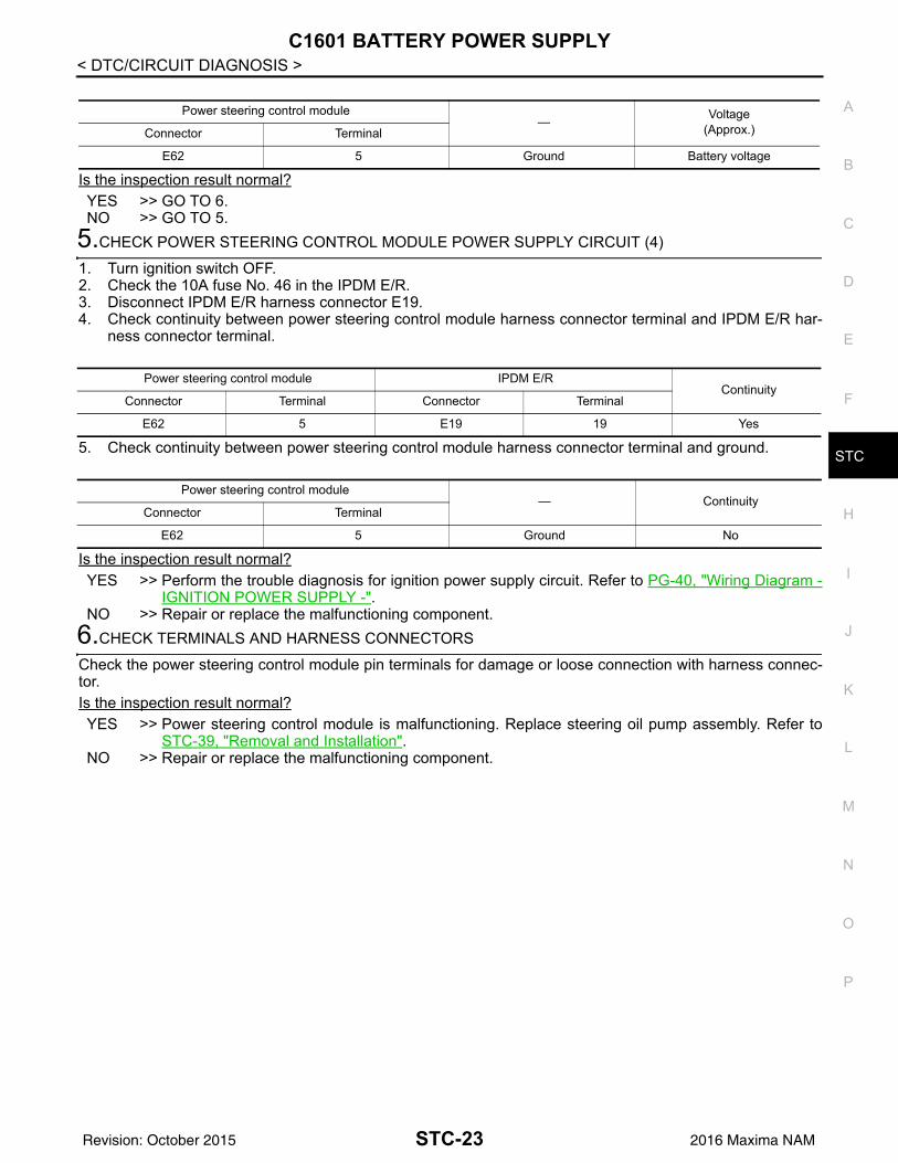
5.CHECK POWER STEERING CONTROL MODULE POWER SUPPLY CIRCUIT (4)
1. Turn ignition switch OFF.2. Check the 10A fuse No. 46 in the IPDM E/R.3. Disconnect IPDM E/R harness connector E19.4. Check continuity between power steering control module harness connector terminal and IPDM E/R har-
ness connector terminal.
5. Check continuity between power steering control module harness connector terminal and ground.
Is the inspection result normal?YES >> Perform the trouble diagnosis for ignition power supply circuit. Refer to PG-40, "Wiring Diagram -
IGNITION POWER SUPPLY -".NO >> Repair or replace the malfunctioning component.
6.CHECK TERMINALS AND HARNESS CONNECTORS
Check the power steering control module pin terminals for damage or loose connection with harness connec-tor.Is the inspection result normal?YES >> Power steering control module is malfunctioning. Replace steering oil pump assembly. Refer to
STC-39, "Removal and Installation".NO >> Repair or replace the malfunctioning component.
Power steering control module— Voltage
(Approx.)Connector Terminal
E62 5 Ground Battery voltage
Power steering control module IPDM E/RContinuity
Connector Terminal Connector Terminal
E62 5 E19 19 Yes
Power steering control module— Continuity
Connector Terminal
E62 5 Ground No
STC-23Revision: October 2015 2016 Maxima NAM

C1602 NO TUNING SET
< DTC/CIRCUIT DIAGNOSIS >C1602 NO TUNING SETDTC Logic INFOID:0000000012338988DTC DETECTION LOGIC
POSSIBLE CAUSE• Harness or connectors • Power steering control module
FAIL-SAFE—
DTC CONFIRMATION PROCEDURE1.PRECONDITIONING
If “DTC CONFIRMATION PROCEDURE” has been previously conducted, always turn ignition switch OFF andwait at least 10 seconds before conducting the next test.
>> GO TO 2.2.DTC REPRODUCTION PROCEDURE
CONSULT1. Turn the ignition switch OFF to ON.2. Perform “Self Diagnostic Result” mode of “EPS”.Is DTC “C1602” detected?YES >> Proceed to diagnosis procedure. Refer to STC-24, "Diagnosis Procedure".NO >> Inspection End.
Diagnosis Procedure INFOID:0000000012338989
1.PERFORM SELF-DIAGNOSIS
CONSULT1. Turn the ignition switch OFF to ON.2. Erase “Self Diagnostic Result” mode of “EPS”.3. Turn the ignition switch OFF and wait for at least 10 seconds.4. Perform “Self Diagnostic Result” mode of “EPS”.Is DTC “C1602” detected?YES >> Power steering control module is malfunctioning. Replace power steering oil pump assembly.
Refer to STC-39, "Removal and Installation".NO >> Check pin terminal and connection of each harness connector for malfunctioning conditions.
DTC No. CONSULT screen terms (Trouble diagnosis content) DTC detection condition
C1602 NO TUNING SET
Diagnosis condition Electronic control module error
Signal (terminal) -
Threshold -
Diagnosis delay time -
STC-24Revision: October 2015 2016 Maxima NAM
C1606 EPS MOTOR
C
D
E
F
H
I
J
K
L
M
A
B
TC
N
O
P
< DTC/CIRCUIT DIAGNOSIS >
S
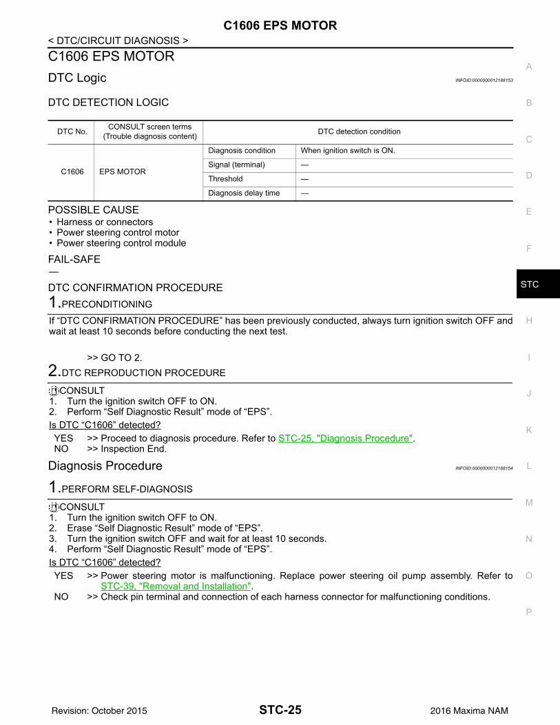
C1606 EPS MOTORDTC Logic INFOID:0000000012188153
DTC DETECTION LOGIC
POSSIBLE CAUSE• Harness or connectors • Power steering control motor• Power steering control module
FAIL-SAFE—
DTC CONFIRMATION PROCEDURE1.PRECONDITIONING
If “DTC CONFIRMATION PROCEDURE” has been previously conducted, always turn ignition switch OFF andwait at least 10 seconds before conducting the next test.
>> GO TO 2.2.DTC REPRODUCTION PROCEDURE
CONSULT1. Turn the ignition switch OFF to ON.2. Perform “Self Diagnostic Result” mode of “EPS”.Is DTC “C1606” detected?YES >> Proceed to diagnosis procedure. Refer to STC-25, "Diagnosis Procedure".NO >> Inspection End.
Diagnosis Procedure INFOID:0000000012188154
1.PERFORM SELF-DIAGNOSIS
CONSULT1. Turn the ignition switch OFF to ON.2. Erase “Self Diagnostic Result” mode of “EPS”.3. Turn the ignition switch OFF and wait for at least 10 seconds.4. Perform “Self Diagnostic Result” mode of “EPS”.Is DTC “C1606” detected?YES >> Power steering motor is malfunctioning. Replace power steering oil pump assembly. Refer to
STC-39, "Removal and Installation".NO >> Check pin terminal and connection of each harness connector for malfunctioning conditions.
DTC No. CONSULT screen terms (Trouble diagnosis content) DTC detection condition
C1606 EPS MOTOR
Diagnosis condition When ignition switch is ON.
Signal (terminal) —
Threshold —
Diagnosis delay time —
STC-25Revision: October 2015 2016 Maxima NAM
C1607, C1608 POWER STEERING CONTROL MODULE
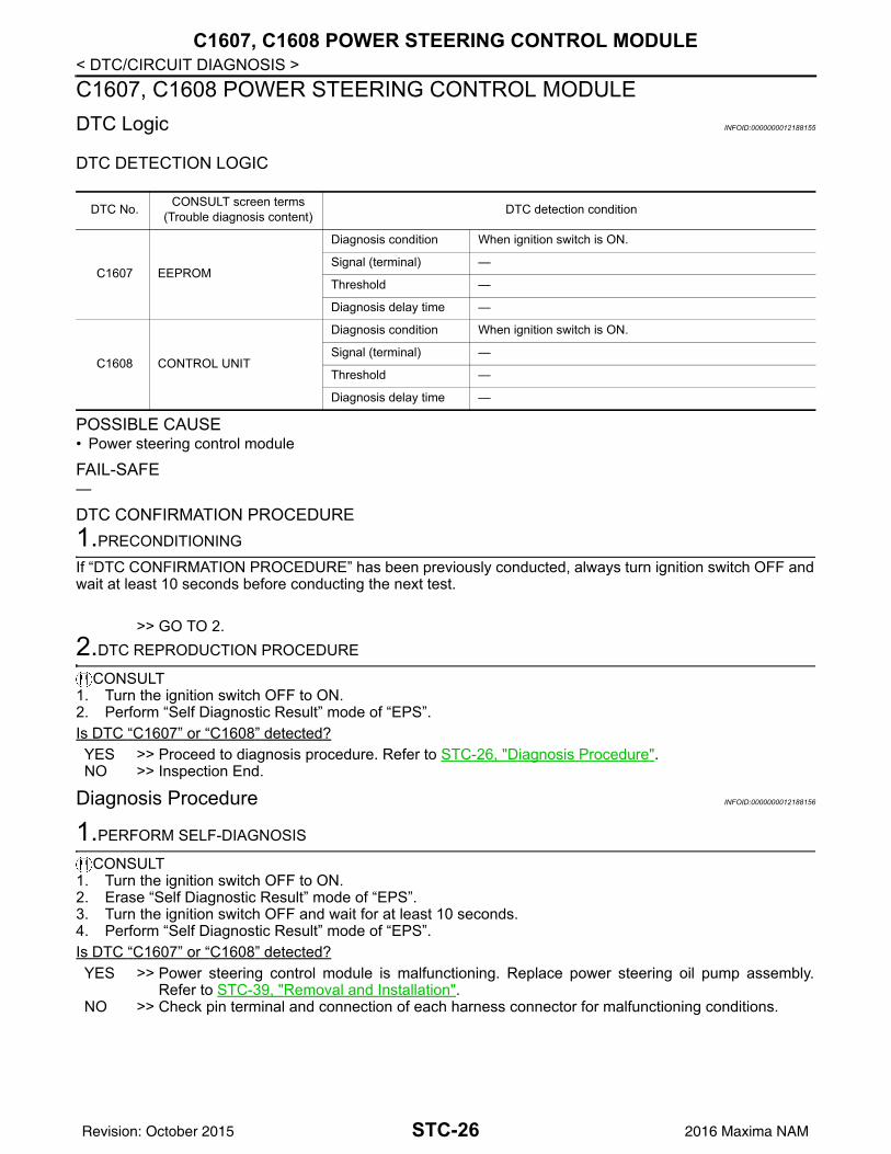
< DTC/CIRCUIT DIAGNOSIS >C1607, C1608 POWER STEERING CONTROL MODULEDTC Logic INFOID:0000000012188155DTC DETECTION LOGIC
POSSIBLE CAUSE• Power steering control module
FAIL-SAFE—
DTC CONFIRMATION PROCEDURE1.PRECONDITIONING
If “DTC CONFIRMATION PROCEDURE” has been previously conducted, always turn ignition switch OFF andwait at least 10 seconds before conducting the next test.
>> GO TO 2.2.DTC REPRODUCTION PROCEDURE
CONSULT1. Turn the ignition switch OFF to ON.2. Perform “Self Diagnostic Result” mode of “EPS”.Is DTC “C1607” or “C1608” detected?YES >> Proceed to diagnosis procedure. Refer to STC-26, "Diagnosis Procedure".NO >> Inspection End.
Diagnosis Procedure INFOID:0000000012188156
1.PERFORM SELF-DIAGNOSIS
CONSULT1. Turn the ignition switch OFF to ON.2. Erase “Self Diagnostic Result” mode of “EPS”.3. Turn the ignition switch OFF and wait for at least 10 seconds.4. Perform “Self Diagnostic Result” mode of “EPS”.Is DTC “C1607” or “C1608” detected?YES >> Power steering control module is malfunctioning. Replace power steering oil pump assembly.
Refer to STC-39, "Removal and Installation".NO >> Check pin terminal and connection of each harness connector for malfunctioning conditions.
DTC No. CONSULT screen terms (Trouble diagnosis content) DTC detection condition
C1607 EEPROM
Diagnosis condition When ignition switch is ON.
Signal (terminal) —
Threshold —
Diagnosis delay time —
C1608 CONTROL UNIT
Diagnosis condition When ignition switch is ON.
Signal (terminal) —
Threshold —
Diagnosis delay time —
STC-26Revision: October 2015 2016 Maxima NAM

C1609 VEHICLE SPEED SIGNAL
C
D
E
F
H
I
J
K
L
M
A
B
TC
N
O
P
< DTC/CIRCUIT DIAGNOSIS >
S
C1609 VEHICLE SPEED SIGNALDTC Logic INFOID:0000000012337414
DTC DETECTION LOGIC
POSSIBLE CAUSE• Harness or connectors • EPS control unit• ABS malfunction • Vehicle speed signal error
FAIL-SAFE—
DTC CONFIRMATION PROCEDURE1.PRECONDITIONING
If “DTC CONFIRMATION PROCEDURE” has been previously conducted, always turn ignition switch OFF andwait at least 10 seconds before conducting the next test.
>> GO TO 2.2.DTC REPRODUCTION PROCEDURE
CONSULT1. Turn the ignition switch OFF to ON.2. Perform “Self Diagnostic Result” mode of “EPS”.Is DTC “C1609” detected?YES >> Proceed to diagnosis procedure. Refer to STC-27, "Diagnosis Procedure".NO >> Inspection End.
Diagnosis Procedure INFOID:0000000012337415
1.PERFORM ABS ACTUATOR AND ELECTRIC UNIT (CONTROL UNIT) SELF-DIAGNOSIS
CONSULT1. Turn the ignition switch OFF to ON.2. Perform “Self Diagnostic Result” mode of “ABS”. Is any DTC detected?YES >> Check the DTC.NO >> GO TO 2.
2.PERFORM SELF-DIAGNOSIS
CONSULTPerform “Self Diagnostic Result” mode of “EPS”.Is DTC “C1609” detected?YES >> Replace EPS control unit. Refer to STC-39, "Removal and Installation".
DTC No. CONSULT screen terms (Trouble diagnosis content) DTC detection condition
C1609 CAN VHCL SPEED
Diagnosis condition
• Malfunction is detected in vehicle speed signal that is output from ABS actuator and electric unit (control unit) via CAN communication.
• ABS actuator and electric unit (control unit) input signal er-ror is detected.
Signal (terminal) Vehicle speed signal
Threshold ABS actuator and electric unit (control unit) input signal error is detected
Diagnosis delay time 2 seconds or more
STC-27Revision: October 2015 2016 Maxima NAM

C1609 VEHICLE SPEED SIGNAL
< DTC/CIRCUIT DIAGNOSIS >NO >> Check EPS control unit pin terminals for damage or loose connection with harness connector. Ifany item are damaged, repair or replace malfunctioning component.
STC-28Revision: October 2015 2016 Maxima NAM

C160A HEAT PROTECTION
C
D
E
F
H
I
J
K
L
M
A
B
TC
N
O
P
< DTC/CIRCUIT DIAGNOSIS >
S
C160A HEAT PROTECTIONDTC Logic INFOID:0000000012188157
DTC DETECTION LOGIC
NOTE:Although the hydraulic pump electric power steering system warning lamp turns ON, this is not a system mal-function. The state returns to normal after stopping steering operation and waiting until the system interiortemperature drops to 90°C (194°F) or less.
POSSIBLE CAUSE• The protection function of the hydraulic pump electric power steering system
FAIL-SAFE—
DTC CONFIRMATION PROCEDURE1.PRECONDITIONING
If “DTC CONFIRMATION PROCEDURE” has been previously conducted, always turn ignition switch OFF andwait at least 10 seconds before conducting the next test.
>> GO TO 2.2.DTC REPRODUCTION PROCEDURE
CONSULT1. Turn the ignition switch OFF to ON.2. Perform “Self Diagnostic Result” mode of “EPS”.Is DTC “C160A” detected?YES >> Go to STC-17, "Work Flow".NO >> Inspection End.
DTC No. CONSULT screen terms (Trouble diagnosis content) DTC detection condition
C160A HEAT PROTECTION
Diagnosis condition When ignition switch is ON.
Signal (terminal) —
ThresholdWhen the steering wheel is operated excessively and the in-terior temperature of the power steering system reaches 118°C (244.4°F) or more (protection function)
Diagnosis delay time —
STC-29Revision: October 2015 2016 Maxima NAM

U1000 CAN COMM CIRCUIT
< DTC/CIRCUIT DIAGNOSIS >U1000 CAN COMM CIRCUITDescription INFOID:0000000012188158CAN (Controller Area Network) is a serial communication line for real-time application. It is an on-vehicle mul-tiplex communication line with high data communication speed and excellent error detection ability. Many elec-tronic control units are equipped onto a vehicle, and each control unit shares information and links with othercontrol units during operation (not independent). In CAN communication, control units are connected with 2communication lines (CAN-H line, CAN-L line), allowing a high rate of information transmission with less wir-ing. Each control unit communicates data but selectively reads required data only.
DTC Logic INFOID:0000000012188159
DTC DETECTION LOGIC
POSSIBLE CAUSE• CAN communication error
FAIL-SAFE—
DTC CONFIRMATION PROCEDURE1.PRECONDITIONING
If “DTC CONFIRMATION PROCEDURE” has been previously conducted, always turn ignition switch OFF andwait at least 10 seconds before conducting the next test.
>> GO TO 2.2.DTC REPRODUCTION PROCEDURE
CONSULT1. Turn the ignition switch OFF to ON.2. Perform “Self Diagnostic Result” mode of “EPS”.Is DTC “U1000” detected?YES >> Go to STC-30, "Diagnosis Procedure".NO >> Inspection End.
Diagnosis Procedure INFOID:0000000012188160
Proceed to LAN-17, "Trouble Diagnosis Flow Chart".
DTC No. CONSULT screen terms (Trouble diagnosis content) DTC detection condition
U1000 CAN COMM CIRCUIT
Diagnosis condition When ignition switch is ON.
Signal (terminal) —
Threshold —
Diagnosis delay time —
STC-30Revision: October 2015 2016 Maxima NAM
HYDRAULIC PUMP ELECTRIC POWER STEERING WARNING LAMP
C
D
E
F
H
I
J
K
L
M
A
B
TC
N
O
P
< DTC/CIRCUIT DIAGNOSIS >
S
HYDRAULIC PUMP ELECTRIC POWER STEERING WARNING LAMPComponent Function Check INFOID:0000000012188161
1.CHECK THE ILLUMINATION OF THE HYDRAULIC PUMP ELECTRIC POWER STEERING WARNINGLAMPCheck that the hydraulic pump electric power steering warning lamp turns ON when ignition switch turns ON.Then, hydraulic pump electric power steering warning lamp turns OFF after the engine is started.Is the inspection result normal?YES >> Inspection End.NO >> Perform trouble diagnosis. Refer to STC-31, "Diagnosis Procedure".
Diagnosis Procedure INFOID:0000000012188162
1.PERFORM SELF DIAGNOSIS
CONSULT1. Turn the ignition switch OFF to ON.2. Perform “Self Diagnostic Result” mode of “EPS”.Is any DTC detected?YES >> Check the DTC. Refer to STC-13, "DTC Index".NO >> GO TO 2.
2.CHECK HYDRAULIC PUMP ELECTRIC POWER STEERING WARNING LAMP SIGNAL
CONSULT1. Turn the ignition switch ON.2. Select “WARNING LAMP” in “Data Monitor” mode of “EPS”.3. Check that the item in “Data Monitor” mode is “On”.
CAUTION:Engine should not be running for step 3.
4. Start the engine.CAUTION:Never drive the vehicle during the test.
5. Check that the item in “Data Monitor” mode is “Off”.Is the inspection result normal?YES >> Perform the trouble diagnosis for combination meter power supply circuit. Refer to MWI-50,
"COMBINATION METER : Diagnosis Procedure".NO >> GO TO 3.
3.CHECK TERMINALS AND HARNESS CONNECTORS
Check the power steering control module pin terminals for damage or loose connection with harness connec-tor.Is the inspection result normal?YES >> Power steering control module is malfunctioning. Replace power steering oil pump assembly.
Refer to STC-39, "Removal and Installation".NO >> Repair or replace the malfunctioning component.
STC-31Revision: October 2015 2016 Maxima NAM
HYDRAULIC PUMP ELECTRIC POWER STEERING WARNING LAMP DOES NOT TURN ON
< SYMPTOM DIAGNOSIS >
SYMPTOM DIAGNOSISHYDRAULIC PUMP ELECTRIC POWER STEERING WARNING LAMPDOES NOT TURN ONDescription INFOID:0000000012188163
The hydraulic pump electric power steering warning lamp does not illuminate when the ignition switch isturned ON (lamp check).
Diagnosis Procedure INFOID:0000000012188164
1.CHECK THE HYDRAULIC PUMP ELECTRIC POWER STEERING WARNING LAMP
Perform trouble diagnosis for the hydraulic pump electric power steering warning lamp system. Refer to STC-31, "Diagnosis Procedure".Is the inspection result normal?YES >> Check that the pin terminals and the connection of each connector are normal.NO >> Repair or replace the malfunctioning components.
STC-32Revision: October 2015 2016 Maxima NAM

HYDRAULIC PUMP ELECTRIC POWER STEERING WARNING LAMP DOES NOT TURN OFF
C
D
E
F
H
I
J
K
L
M
A
B
TC
N
O
P
< SYMPTOM DIAGNOSIS >
S
HYDRAULIC PUMP ELECTRIC POWER STEERING WARNING LAMPDOES NOT TURN OFFDescription INFOID:0000000012188165
Hydraulic pump electric power steering warning lamp does not turn OFF several seconds after engine isstarted.
Diagnosis Procedure INFOID:0000000012188166
1.PERFORM SELF DIAGNOSIS
CONSULTPerform “Self Diagnostic Result” mode of “EPS”.Is any DTC detected?YES >> Check the DTC. Refer to STC-13, "DTC Index".NO >> GO TO 2.
2.CHECK HYDRAULIC PUMP ELECTRIC POWER STEERING WARNING LAMP
Perform the trouble diagnosis of hydraulic pump electric power steering warning lamp. Refer to STC-31,"Diagnosis Procedure".Is the inspection result normal?YES >> GO TO 3.NO >> Repair or replace the malfunctioning components.
3.POWER STEERING CONTROL MODULE POWER SUPPLY AND GROUND CIRCUIT
Perform the trouble diagnosis of power steering control module power supply and ground. Refer to STC-21,"Diagnosis Procedure".Is the inspection result normal?YES >> Check that the pin terminals and the connection of each connector are normal.NO >> Repair or replace the malfunctioning components.
STC-33Revision: October 2015 2016 Maxima NAM

STEERING WHEEL TURNING FORCE IS HEAVY OR LIGHT
< SYMPTOM DIAGNOSIS >STEERING WHEEL TURNING FORCE IS HEAVY OR LIGHTDiagnosis Procedure INFOID:00000000121881671.PERFORM SELF DIAGNOSIS
CONSULTPerform “Self Diagnostic Result” mode of “EPS”.Is a malfunctioning system displayed?YES >> Check malfunctioning system. Refer to STC-13, "DTC Index".NO >> GO TO 2.
2.CHECK THE POWER STEERING CONTROL MODULE SIGNAL (1)
CONSULT1. Start the engine.
CAUTION:Never drive the vehicle.
2. Turn the steering wheel until it stops.3. Select “MTR ASSIST” in “Data Monitor” mode of “EPS”.Is the display value “100%”?YES >> GO TO 4.NO >> GO TO 3.
3.CHECK THE POWER STEERING CONTROL MODULE SIGNAL (2)
CONSULT1. Select “C/U TEMP” and “C/U TEMP A” in “Data Monitor” mode of “EPS”.2. Stop the system until the “Data Monitor” mode display value drops to 90°C (194°F) or less.3. Check whether symptom continues.Does symptom continue?YES >> GO TO 4.NO >> This occurs because the protection function lowers the assist force. It is not a system malfunction.
Inspection End.4.CHECK THE POWER STEERING CONTROL MODULE SIGNAL (3)
CONSULT1. Turn the steering wheel to the straight-ahead position. (There is no steering force.)2. Select “BATTERY VOLT” in “Data Monitor” mode of “EPS”.Is the display value 10.5 V or more?YES >> GO TO 5.NO >> Check the battery power system. Refer to STC-21, "Diagnosis Procedure".
5.CHECK THE POWER STEERING CONTROL MODULE SIGNAL (4)
CONSULTSelect “ESTM VHCL SPD” in “Data Monitor” mode of “EPS”.
*: This may not agree with the speedometer indication immediately after the ignition switch is turned ON. Thisis not a malfunction.Is the inspection result normal?YES >> GO TO 6.NO >> Check the combination meter and ABS actuator and electric unit (control unit). Refer to MWI-20,
"CONSULT Function (METER/M&A)" and BRC-212, "CONSULT Function".
Monitor item Test condition Display value
ESTM VHCL SPD
When stopped 0.00 km/h or mph
While drivingApproximately equal to the indication on speedometer*(Inside ±10%)
STC-34Revision: October 2015 2016 Maxima NAM

STEERING WHEEL TURNING FORCE IS HEAVY OR LIGHT
C
D
E
F
H
I
J
K
L
M
A
B
TC
N
O
P
< SYMPTOM DIAGNOSIS >
S
6.CHECK THE POWER STEERING CONTROL MODULE SIGNAL (5)
CONSULTSelect “STR ANG SPD” in “Data Monitor” mode of “EPS”.
Is the check result normal?YES >> GO TO 7.NO >> Check the steering angle sensor. Refer to STC-20, "Diagnosis Procedure".
7.CHECK THE POWER STEERING CONTROL MODULE SIGNAL (6)
CONSULTSelect “ENGINE STATUS” in “Data Monitor” mode of “EPS”.Is the display value “RUN”?YES >> GO TO 8.NO >> Check the ECM. Refer to EC-73, "CONSULT Function".
8.CHECK THE STEERING FORCE
Check the steering force. Refer to STC-36, "Diagnosis Procedure".Is the inspection result normal?YES >> Inspection End.NO >> It is possible that there is a mechanical malfunction. Check the steering system.
Monitor item Test condition Display value
STR ANG SPD The steering wheel is not steered. Approx. 0.0 deg/s
The steering wheel is steered. Displays steering angle speed (deg/s)
STC-35Revision: October 2015 2016 Maxima NAM

UNBALANCE STEERING WHEEL TURNING FORCE AND RETURN BETWEEN RIGHT AND LEFT
< SYMPTOM DIAGNOSIS >UNBALANCE STEERING WHEEL TURNING FORCE AND RETURN BE-TWEEN RIGHT AND LEFTDiagnosis Procedure INFOID:0000000012188168
1.CHECK THE ILLUMINATION OF THE HYDRAULIC PUMP ELECTRIC POWER STEERING WARNINGLAMPCheck the hydraulic pump electric power steering warning lamp while engine is running.Does the hydraulic pump electric power steering warning lamp turn OFF?YES >> GO TO 2.NO >> Refer to STC-33, "Diagnosis Procedure".
2.CHECK WHEEL ALIGNMENT
Check the wheel alignment. Refer to FSU-7, "Inspection".Is the inspection result normal?YES >> GO TO 3.NO >> Adjustment of wheel alignment. Refer to FSU-7, "Inspection".
3.CHECK STEERING WHEEL TURNING FORCE
Check the steering wheel turning force. Refer to STC-37, "Diagnosis Procedure".Is the inspection result normal?YES >> Inspection End.NO >> Check the steering wheel turning force for mechanical malfunction. Refer to STC-34, "Diagnosis
Procedure".
STC-36Revision: October 2015 2016 Maxima NAM

UNBALANCE STEERING WHEEL TURNING FORCE (TORQUE VARIATION)
C
D
E
F
H
I
J
K
L
M
A
B
TC
N
O
P
< SYMPTOM DIAGNOSIS >
S
UNBALANCE STEERING WHEEL TURNING FORCE (TORQUE VARIA-TION)Diagnosis Procedure INFOID:0000000012188169
1.PERFORM SELF-DIAGNOSIS
CONSULTPerform “Self Diagnostic Result” mode of “EPS”.Is a malfunctioning system displayed?YES >> Check malfunctioning system. Refer to STC-13, "DTC Index".NO >> GO TO 2.
2.CHECK THE POWER STEERING CONTROL MODULE SIGNAL (1)
CONSULT1. Start the engine.
CAUTION:Never drive the vehicle.
2. Turn the steering wheel until it stops.3. Select “MTR ASSIST” in “Data Monitor” mode of “EPS”.Is the display value “100%”?YES >> GO TO 4.NO >> GO TO 3.
3.CHECK THE POWER STEERING CONTROL MODULE SIGNAL (2)
CONSULT1. Select “C/U TEMP” and “C/U TEMP A” in “Data Monitor” mode of “EPS”.2. Stop the system until the “Data Monitor” mode display value drops to 90°C (194°F) or less.3. Check whether symptom continues.Does symptom continue?YES >> GO TO 4.NO >> This occurs because the protection function lowers the assist force. It is not a system malfunction.
Inspection End.4.CHECK THE POWER STEERING CONTROL MODULE SIGNAL (3)
CONSULT1. Turn the steering wheel to the straight-ahead position. (There is no steering force.)2. Select “BATTERY VOLT” in “Data Monitor” mode of “EPS”.Is the display value 10.5 V or more?YES >> GO TO 5.NO >> Check the battery power system. Refer to STC-21, "Diagnosis Procedure".
5.CHECK THE POWER STEERING CONTROL MODULE SIGNAL (4)
CONSULTSelect “ESTM VHCL SPD” in “Data Monitor” mode of “EPS”.
*: This may not agree with the speedometer indication immediately after the ignition switch is turned ON. Thisis not a malfunction.Is the inspection result normal?YES >> GO TO 6.
Monitor item Test condition Display value
ESTM VHCL SPD
When stopped 0.00 km/h or mph
While drivingApproximately equal to the indication on speedometer*(Inside ±10%)
STC-37Revision: October 2015 2016 Maxima NAM

UNBALANCE STEERING WHEEL TURNING FORCE (TORQUE VARIATION)
< SYMPTOM DIAGNOSIS >NO >> Check the combination meter and ABS actuator and electric unit (control unit). Refer to MWI-20,"CONSULT Function (METER/M&A)" and BRC-212, "CONSULT Function".6.CHECK THE POWER STEERING CONTROL MODULE SIGNAL (5)
CONSULTSelect “STR ANG SPD” in “Data Monitor” mode of “EPS”.
Is the inspection result normal?YES >> GO TO 7.NO >> Check the steering angle sensor. Refer to STC-20, "Diagnosis Procedure".
7.CHECK THE POWER STEERING CONTROL MODULE SIGNAL (6)
CONSULTSelect “ENGINE STATUS” in “Data Monitor” mode of “EPS”.Is the display value “RUN”?YES >> GO TO 8.NO >> Check the ECM. Refer to EC-73, "CONSULT Function".
8.CHECK STEERING COLUMN AND STEERING GEAR
Check the steering column assembly and steering gear assembly.• Steering column assembly: Refer to ST-17, "Inspection".• Steering gear assembly: Refer to ST-19, "Inspection".Is the inspection result normal?YES >> GO TO 9.NO >> Repair or replace malfunctioning component.
9.CHECK STEERING WHEEL TURNING FORCE
Check the steering wheel turning force. Refer to STC-34, "Diagnosis Procedure".Is the inspection result normal?YES >> Inspection End.NO >> Check the steering wheel turning force for mechanical malfunction. Refer to STC-34, "Diagnosis
Procedure".
Monitor item Test condition Display value
STR ANG SPD The steering wheel is not turning. Approx. 0.0 deg/s
The steering wheel is being turned. Displays steering angle speed (deg/s)
STC-38Revision: October 2015 2016 Maxima NAM
POWER STEERING CONTROL MODULE
C
D
E
F
H
I
J
K
L
M
A
B
TC
N
O
P
< REMOVAL AND INSTALLATION >
S
REMOVAL AND INSTALLATIONPOWER STEERING CONTROL MODULERemoval and Installation INFOID:0000000012188170
CAUTION:Disconnect battery negative cable before removing the power steering oil pump.The power steering control module is an integral part of the power steering oil pump. If replacement of thepower steering control module is necessary, replace the complete power steering oil pump. Refer to ST-43,"Removal and Installation".
STC-39Revision: October 2015 2016 Maxima NAM