steam methane reforming in molten carbonate salt .../67531/metadc665981/m2/1/high_re… ·...
TRANSCRIPT

0
0
e
0
0
D
FINAL REPORT
STEAM METHANE REFORMING IN MOLTEN CARBONATE SALT
Department of Energy ERlP Grant No. DE FGOl-91 CEI 5404
May 1996
Prepared for:
US Department of Energy
Prepared by:
D. C. Erickson
Energy Concepts Co. 627 Ridgely Avenue
Annapolis, MD 21401
B

DISCLAIMER
Portions of this document may be ilregible in electronic image products. Images are produced h m the best available onginaI dOCUIIlellt

FINAL REPORT
STEAM METHANE REFORMING IN MOLTEN CARBONATE SALT
Department of Energy ERlP Grant DE FGOl-91 CEI 5404
May 1996
1. EXECUTIVE SUMMARY
This report documents the work accomplished on the project “Steam
Methane Reforming in Molten Carbonate Salt.”
This work was financed by DOE Grant DE FGOl-91 CEI 5404 under the
Energy Related Inventions Program. The invention was submitted to NlST and
received a favorable recommendation (ERlP Recommendation 404). Contractual effort commenced on September 16, 1991 , and continued until all
contract funds were expended. As explained below, work is continuing on a
particularly promising aspect of this technology under internal funding.
This effort has established the conceptual basis for molten carbonate-
based steam reforming of methane. It has not proceeded to prototype
verification, because corrosion concerns have led to reluctance on the part of
large hydrogen producers to adopt the technology. Therefore the focus was
shifted to a less corrosive embodiment of the same technology. After
considerable development effort there, it was discovered that a European
company (Catalysts and Chemicals Europe) was developing a similar process
(“Regate”). Accordingly the focus was shifted a second time, to develop an
improvement which is generic to both types of reforming. That work is still in
progress, and shows substantial promise.
This report is organized as follows. The background section describes the
industrial importance of hydrogen, the methods of producing it, and the
shortcomings of current production methods. Section 3 describes the
advantages of a promising embodiment of the molten carbonate approach to
reforming. Section 4 describes use of an immobilized molten carbonate salt to
1

0
0
0
0
0
0
0
0
alleviate corrosion concerns, and compares it to the Regate process. Section 5
describes energy enhancements for both approaches.
2. BACKGROUND Hydrogen is a major industrial commodity which plays an important role in
many processes. It is almost always an intermediate, as opposed to an end
product, and hence its central role is not well known to the public. The two major
uses of hydrogen are in petroleum refining and fertilizer manufacture (NH3 ).
There are dozens of lesser uses, ranging from methanol and oxoalcohol
manufacture to edible oil hydrogenation. Most of the hydrogen consumed in refineries is a byproduct from other refining operations, e.g., catalytic cracking.
Thus the NH3 industry is the leading consumer of manufactured hydrogen, as
opposed to byproduct hydrogen.
partial oxidation (using pure 0,) a distant second. The feedstock for steam
reforming can be natural gas, LPG, or naphtha.
Steam reforming is by far the dominant HZ production technology, with
The American Institute for Chemical Engineers (AIChE) sponsors a major symposium every year entitled, "Ammonia Plant and Related Facilities Safety."
The proceedings of those symposia are the most comprehensive literature
source for up-to-date information on steam reforming, and form the basis for
much of the following information.
There are three characteristics of the steam reforming reaction of
methane:
CH4 + H20 = CO + 3H2 that result in processing difficulties. First, CH4 is a relatively refractory gas; high
temperatures are necessary to make the reform reaction proceed even in the
presence of a catalyst. The reaction is endothermic; heat must be supplied at the
required high temperature without adding undesirable components to the
synthesis gas such as excess nitrogen. High concentration of CO can result in
carbon deposition according to the reverse Bouduard reaction:
CO(g) = c + COz(g)
2

0
0
0
I,
0
0
I,
e
0
e
The current practice of reforming is to pass the reactants through catalyst-filled
tubes that are radiantly heated from outside by combustion gases. The
difficulties mentioned above lead to a number of trade-offs or problems. High
reform temperatures are desirable from both equilibrium and kinetic considerations. High pressures, although adversely affecting equilibrium, are beneficial to kinetics. More important, high reform pressures are desired
because it is more economical to pressurize the reform reactants than to
compress the product hydrogen. However, the actual pressure and temperature
must be traded off against metallurgical limitations. The current reformer tubes
operate at the frontier of metallurgical capability -- 33 atmosphere and 870°C
internal temperature. These tubes are made of a super-alloy such as HP 40:
25% Cr, 35% Ni, balance Fe. High temperature differences across the tube wall are used to minimize the required number of tubes for a given heat flux. Thus
the combustion gas temperature is typically 980°C. These conditions yield a
nominal tube life of 10 years.
Since the reform temperature is limited by tube metallurgy, it is necessary
to add more than the stoichiometric amount of steam, both to ensure adequate
conversion of methane and to guard against carbon deposition. The reform
catalyst is deactivated by carbon deposition, which is promoted by lower
temperatures. Current steam reformers use a steam-to-methane ratio of 3.2 to
3.6. The stoichiometric requirement is 1 for the reformer alone, or 2 for the
combination of reformer plus shift converter:
2H20 + CH4 = 4H2 + COz The extra steam added in current reformers provides a margin against carbon deposition even under upset conditions. However, it represents an energy loss both in raising the steam and in providing the extra combustion necessary to
heat it to 870°C. It also adds to the size and cost of downstream equipment.
Recently there has been a growing interest in lowering the steamlgas
ratio to the reformer and thereby reducing the energy requirement of the
process. Reductions from the normal range of 3.2 to 3.6 to as low as 2.5 have
3

I)
0
0
@
0
0
0
been demonstrated. However, it is acknowledged that this causes operation
nearer to carbon deposition conditions, higher tube temperatures and shortened
tube life. The adverse consequences of a short excursion into the carbon
deposition region, and the effect on the catalyst operation, have been
described. This may only be minor carbon deposition. Minor carbon deposition
on the catalyst can be removed by a regeneration technique requiring about 24
hours. However, if the buildup is severe enough to cause plugging, tube
overheating will occur and the tube must be isolated or replaced.
3. MOLTEN CARBONATE REFORMER This invention utilizes molten carbonate salt in lieu of conventional
catalyst tubes as a reform reaction medium. Prior art patents which are relevant
to the use of molten salt as a chemically reactive medium include the following:
Bond et al., (US Patent 2,754,187) teach a process for converting normally
gaseous hydrocarbons, optionally admixed with a minor portion of steam, to a
mixture of H2 and CO. The reactants are contacted with molten alkali carbonate in the temperature range of 760°C to 1095°C so as to produce alkali metal oxide,
and the alkali metal oxide is separately contacted with submerged combustion
gases to reconvert the oxide to carbonate.
Kepp et al., (US Patent 2,844,453) teach contacting normally gaseous
hydrocarbons with alkali carbonate so as to form alkali metal oxide, and
regenerating the oxide to carbonate by contact with hot flue gas.
McMahon et al., (US Patent 3,252,774) teach a salt reforming process
wherein normally liquid hydrocarbon and steam are reformed by contact with
alkali metal carbonate and hydroxide salt. The reaction heat is supplied
indirectly to the salt by an external source. It is disclosed that methane reforming
is at an infeasible level in 29 w/o Li2C03, 71 w/o Na2C03 at a steamlcarbon ratio
below 2.2 and a temperature of 816°C.
Shalit et al., (US Patent 3,786,138) disclose producing pure hydrogen by
reacting carbonaceous material and steam with alkali metal hydroxide which is
4

substantially free of alkali metal carbonate, and separately oxidizing part of the
alkali metal hydroxide to alkali metal peroxide by contact with air.
Prior art patents which involve reacting solid carbonaceous materials with
steam in the presence of molten alkali metal carbonate include US Patents
3,252,773, 3,708,270, and 3,740,103.
As detailed below, the molten carbonate reform invention provides a
process and apparatus capable of reforming a mixture of steam and normally
gaseous hydrocarbons (methane or natural gas) to synthesis gas at
economically feasible yields (better than 65% methane conversion) and at
economical steamkarbon ratios (1 to 3) using practical temperatures (below
930°C), and with economical salt regeneration.
3.1. Disclosure Of Molten Carbonate Reform Invention
The reform reactants, a mixture of gaseous hydrocarbon and steam
having a steamhrbon ratio between 1 and 3, are reformed in a liquid medium
consisting essentially of alkali metal carbonate and hydroxide salts. The melt is
at least 30% each sodium and potassium cations, and between 5 and 30%
hydroxide anions, balance carbonate (all percents are molar percents). Reform
salt temperature is between 830 and 930°C. The salt is separately regenerated
by heating to between 860 and 960°C by submerged combustion of fuel and
oxidizer (e.g., air), for recycle to the reform reaction. The residence time of the
reform reactants in contact with the salt, between about 1 and 20 seconds, is
selected such that between 65 and 90% of the methane is reacted. Unreacted
methane is separated from the synthesis gas after CO shift and COS scrub, and then used as part of the fuel for the submerged combustion regeneration reactions, or is recycled to reactant CH4. There is essentially no alkali metal
oxide in the salt melt (less than 1 ppm) during reform or regeneration. The
inclusion of cesium cations in the melt, up to about 25%, both improves the
kinetics and lowers the melting point. Lithium cation lower the melting point but
lengthen the residence time. Up to 5% barium cations is beneficial to kinetics.
5

0
0
0
0
0
0
0
0
0
0
The reform and regeneration reactions are conducted at approximately
the same pressure in the range of 5 to 40 atmosphere. The hot combustion gas
exiting the regeneration zone is preferably filtered and then work expanded.
When ammonia synthesis gas is the product, the air necessary for
stoichiometric N2 for the NHs is preferably introduced directly into the reform
reaction zone with the reform reactants - thus the salt reformer replaces both
the primary and secondary conventional reformers, and the regeneration duty is
lessened. The same compressor supplies both combustion air and reform air.
The compressed air for combustion including the N2for NHs stoichiometry
is preferably heated above 600°C by heat exchange with the hot synthesis gas.
For safety reasons this is preferably done by a double indirect exchange. The
double indirect exchange prevents a single leak from allowing mixing of hot
syngas and hot compressed air.
When low steamkarbon ratios are used, e.g., 2 or less, there is greater
potential for carbon deposition during cooldown of the synthesis gas. One
means of avoiding this is to withdraw part of the reform salt, cool it to near the
melting point by indirect heat exchange with compressed air and/or reform
reactants, and then countercurrently contact it with the hot synthesis gas exiting
the reformer. This both cools the synthesis gas and partially replaces the carbonaceous species (C02 and CO) with H20 and HZ, thus reducing the
tendency to deposit carbon. This also reduces the downstream shift and scrub
duties.
3.2. Brief Description of the Drawings
Figure 1 is a simplified schematic flowsheet of the molten carbonate
reformer incorporating separate reform and regeneration zones, and the system
for delivering hot pressurized reactants to each zone and recovering high temperature heat from the effluent from each zone. Figure 2 is a computer-
generated heat and mass balance of the molten carbonate reformer.
6
0
0
e
e
e
I)
0
e
I,
3.3. Best Mode For Carrying Out The Invention
The molten carbonate reformer comprises an alkali carbonate salt melt
contained in a pressure vessel lined with high-alumina refractory. The gas space
above the melt is divided into separate reform and regeneration zones by a baffle; salt circulates freely under the baffle. Figure 1 illustrates the functioning
of the reformer 1. A mixture of steam and methane is injected into the reform
zone 2, and the synthesis gas is withdrawn at 3. Oxygen (air) plus any necessary fuel for heat addition is injected into the regeneration zone 4, and
combustion exhaust is withdrawn at 5. The molten salt acts as a heat carrier,
conveying reaction heat from the regeneration zone to the reforming zone, as a
catalyst for the steam-methane reaction, and as a liquid seal to prevent the
gases from mixing. There are effectively no metallurgical limits on temperature
or pressure, as the pressure containment is cooled by refractory insulation. The
operating temperature is substantially above the nominal 790°C of current
reformers, thus improving equilibrium and reducing the steam requirement. Also,
carbon deposition in the melt is not detrimental, and may even be turned to
advantage.
Pressure is free to be optimized for the user process, because the vessel
walls, cooled by refractory, can achieve great strength while retaining low cost
carbon steel construction. Pressures between 5 and 40 atmospheres are
contemplated, with 15 to 20 atmospheres preferred.
The remainder of Figure .. 1 illustrates one preferred method of delivering
reactants and combustibles to the reform and regeneration zones respectively.
The flowsheet depicts the ammonia synthesis gas case, i.e., sufficient air is
introduced into the reform zone to yield a synthesis gas having approximate 3 to
1 ratio of H2 to NZ. Air is compressed in compressor 6, and then heated in
exchange with hot synthesis gas in heat exchangers 7 and 8. Those exchangers are preferably of double wall type, with some intermediate fluid between the
syngas pressure boundary and the air pressure boundary. The portion of
compressed air to be used as combustion air is routed through switching filter
7

*
e
e
0
8
a
0
assembly 9, comprised of manifolds 10 and 1 1 , plus filters 12 and 13. The two filters are alternately switched between upflow of combustion exhaust and
downflow of compressed air. The upflow removes virtually all traces of salt from
the exhaust, while cooling it to about 750°C for introduction to the expansion
turbine 14. The downflow cleans accumulated salt from the filter and further preheats the combustion air. The two 4-valve manifolds accomplish the
switching action. The filters may consist simply of random dumped ceramic
packing, e.g., alumina Raschig rings.
Combustion air enters the regeneration zone through one or more lances
15. Fuel can share the same lance or preferably be introduced separately. The
fuel should include some steam and be below 650°C to preclude carbon
plugging of the lance. Similar considerations apply to reform reactants lance 16,
receiving preheated steam and methane from heat exchanger 17.
At reaction pressures above about 10 atmosphere, the compressor would
include at least one intercooler. The turbine preferably directly drives the
compressor. The sensible heat remaining in the turbine exhaust is used to raise
steam in waste heat boiler 18.
There are two distinct modes of operation of this reformer, which achieve
different levels of energy savings. They are distinguished by the relative
amounts of steam supplied to the reform zone and hydrocarbon supplied to the
regeneration zone. At one extreme is the conventional combustion case. All heat
added to the salt is derived from combustion of hydrocarbon supplied to the
regeneration zone. The steam supplied to the reform zone is sufficient to keep
the reform gas suitably outside carbon deposition conditions. Carbon formation
will occur only during temporary upsets and there is no steady-state inventory of
carbon in the melt.
At the other extreme, the hydrocarbon supply to the regeneration zone is
completely eliminated, and the steam supply to the reform zone is substantially
further reduced. Thus extensive carbon deposition into the melt occurs, and the
carbon is transported by the melt to the regeneration zone, where it becomes the
8

a
e
0
*
I)
e
0
0
a
fuel which is combusted by the air supply. At first this modification would not
seem to save additional energy, since the hydrocarbon is merely being shifted
from one salt zone to the other. The key beneficial result, however, is that now
more of the total carbon inventory leaves as C02 in the exhaust gas, and hence there is less inventory of carbonaceous species ( CO and C02 ) in the reformed
gas. This means that less steam is required for downstream shift conversion and
C02 removal. In this latter mode, wherein there is continual generation of carbon
internal to the melt, one concern is to prevent excessive accumulation of carbon
in the reformer. Direct measurement of the carbon inventory would be very
difficult. The planned solution is to monitor the regeneration exhaust for excess
oxygen. Excess oxygen in the exhaust, e.g., 0.5 to 1 %, signifies that all available
carbon in the regenerator has been consumed and that no continuing builldup is
in progress.
4. IMMOBILIZED MOLTEN CARBONATE REFORMER
The molten carbonate reform process as described in the preceding
section has been shown to be technically valid and meritorious for energy
conservation. However it entails high risk due to the corrosive character of the
circulating molten salt. With current low natural gas prices, the economic
benefits of the increased energy efficiency are not sufficient to induce the risk
capital necessary to progress to prototype stage. Accordingly the technology sits
on the shelf, ready to be resurrected in a higher energy cost era.
In order to salvage some practical energy conservation and economic
benefit from the research investment, alternative approaches were sought which would yield the same kind of benefits as molten carbonate reforming, without the corrosive risk.
It was discovered that two generic approaches are possible for accomplishing steam reforming using molten carbonate salt. One is the
“simultaneous” approach wherein reform and regeneration occur at the same
time, but spatially separated, and the molten carbonate forms a liquid seal
9

separating the two compartments. The second approach is "sequential" wherein
the separation between reform and regenerate is accomplished by the time
difference rather than location difference. This approach has the disadvantage
of intermittency, with the gas space alternately cycling between heavily reducing
conditions and neutral conditions. However, since no liquid seal is required, nor
is any circulation of the molten salt required, the sequential approach makes it
possible to immobilize the molten carbonate on solid supports This eliminates
the biggest development risk in molten carbonate reforming - the corrosivity of
the salt melt. The intermittency reduces the energy conservation potential, due
to changeover losses. It also involves having the same vessel alternate between
reducing conditions and neutral conditions with some danger that it could go to
oxidizing during upsets. However that danger is in essence a control problem
not unlike others routinely encountered in industry.
The primary conceptual effort in developing this cycle was working out the
details of a two vessel version, wherein one vessel was in reform mode while the
other regenerated, and then both reverse. That version was compared to a
single vessel version, wherein traveling wave fronts were carefully controlled to
allow both reactions to proceed in a single vessel. Additional effort was
necessary on the gas supply and removal system, especially the work recovery
expander (essentially a gas turbine).
As the conceptual work on the Immobilized Molten Carbonate Reformer
process was completing, it was discovered that a competitor had already
invented a similar process and was commencing development. A paper was
published in the proceedings of the 1991 Ammonia Plant Safety Symposium on
the Regate process. That paper is reproduced as Appendix 1.
The technical Paper, "Regate: a Process to Preheat Gases at High
Temperature under High Pressures," was authored by the European company
"Catalysts and Chemicals Europe SA." Although different from our process in
several details, it nevertheless disclosed the basic concept of sequential
reforming, with regeneration via combustion using pressurized air.
10
5. REFORMER HEAT AND WORK RECOVERY
There is a great deal of high temperature sensible heat available in the
hot reformed gas plus hot combustion exhaust. Some (approximately 113) of that
heat is used to preheat the reform reactants up to about 600"C, but the rest is
used at low temperature (- 320°C) to raise steam, plus a small fraction to
superheat the steam.
Most processes requiring synthesis gas, and especially ammonia
synthesis processes, require a great deal of shaft work to accomplish the various
compression duties. Typically all of the steam generated from waste heat
recovery is used, either for process reactant or for driving a steam turbine to
produce the required shaft work. Thus although hypothetically it is possible to
recover more high temperature heat by heat exchange between reform reactants
and hot gases exiting the reformer, in practice there is no incentive to do so. The
lesser amount of waste heat means less steam is generated, and the steam
deficit would then have to be made up from some other source such as an
auxiliary-fired boiler.
Using steam to generate the necessary shaft work requires almost 4
Joules of heat for every Joule of shaft work generated. Merely recovering more
of the available high temperature waste heat at high temperatures provides no
benefit such as increased steam generation or reduced fuel input requirement.
What is needed is to recover more of the high temperature waste heat so as to
more efficiently produce shaft work. That is one primary objective of the present
invention.
It is known to provide fuel to a gas turbine to produce shaft work, and then
to use the hot (- 500°C) exhaust still containing about 14% O2 as the combustion
air for a reforming furnace. The three-quarters of the fuel energy that ends up as
sensible heat of the turbine exhaust would otherwise have to be supplied at the
reforming furnace. The one-quarter additional fuel energy ends up as shaft work
(net gas turbine output). Although this is an efficient means of converting
additional fuel to shaft work, it takes no added advantage of the existing high
11
temperature exit streams from the reformer, and hence tends to result in a steam
excess. Also, the added gas turbine is a large capital expense, and it must
compress about half again more air than the O2 actually reaching the reforming
furnace would indicate.
US Patent 4,337,170 discloses a steam reforming arrangement wherein two reformers in parallel are used -- one is heated conventionally by combustion
gases, and the other, having a steam-carbon ratio between 3 and 6, is heated by
the combined reformed gas discharged from both reformers. This provides a
more effective recovery of high temperature waste heat, but does not either
reduce the shaft work requirement or increase the efficiency of converting waste
heat to shaft work.
In order to increase the recovery of high temperature reformer waste heat
and more efficiently convert it to useful work the following procedure is
proposed. Air is compressed, then indirectly heated by at least one of the hot
reformed gas and the hot combustion exhaust, then work-expanded, and then
supplied to the reformer furnace as combustion air.
The compressor is most conveniently driven directly by the turbine. For
high compressor discharge pressures, e.g., above about 10 atmospheres, at
least one stage of intercooling will normally be incorporated. When ammonia synthesis gas is being produced, the same compressor can supply part or all of
that duty.
Heat exchange can economically heat the air to above 600"C, and in
some cases to above 750°C. In some cases it will be desirable to add
supplementary fuel to the heated compressed air to raise it to the allowable
turbine inlet temperature, typically 900°C.
close to 20% O2 (usually 20.9%). Thus less air must be compressed to provide
the furnace 0 2 requirements, compared to prior art disclosures having about
15% 02. Also, the higher O2 content provides hotter flames and better radiant heat transfer.
In general the turbine exhaust will be close to 500°C and will contain
12
The heat exchange between compressed air and combustion exhaust
may use any conventional means for heat exchange; brazed plate fin
exchangers, shell and tube exchangers, fin tube thermosyphons, rotary wheels,
and the like. One of the simplest and most economical designs consists of
switching regenerator beds, such as are commonly found in cryogenic air
separation plants and blast furnaces.
When heat is exchanged between compressed air and hot reformed gas,
it is preferably a double indirect exchange for safety considerations, Le., the
compressed air and the reformed gas should not share a common pressure
boundary. Double wall exchangers may be used, or other techniques meeting
the double indirect criterion: fin tube thermosyphons (containing e.g., Na, K, or Cs); pumped liquid loops (molten carbonate salt or NaK), or even pumped
molten salt loops in which one of the heat exchanges is via direct contact.
The greatest conversion of high temperature waste heat to useful shaft
work will be obtained when turbine reheat is used: the compressed air is heated
by one high temperature stream, partially expanded, then heated by the other
stream, and then expansion is completed. To maximize work output, the
pressure ratio across each turbine should be in the range of 3 to 8. Thus
compressor discharge pressures of 10 to 60 atmospheres are in order. A
discharge pressure of about 33 atmospheres to match the secondary air
pressure requirement works particularly well.
When recovering high temperature heat from the hot reformed gas, it is
desirable to maintain approximate water-gas-shift equilibrium. This preserves
the greatest margin against carbon deposition, and has the added beneficial
effect or releasing at least part of the water-gas-shift exothermic reaction heat at
the useful high temperatures. Thus interspersing one or more small containers of
appropriate HTS catalyst at appropriate high temperature locations in the heat exchange train is beneficial.
13

Further energy economy is obtainable by cooling the compressor inlet air below ambient using discharge waste heat as the mode of power. Work continues on this variation
DISCLAIMER
This report was prepared as an account of work sponsored by an agency of the United States Government. Neither the United States Government nor any agency thereof, nor any of their employees, makes any warranty, express or implied, or assumes any legal liability or responsi- bility for the accuracy, completeness, or usefulness of any information, apparatus, product, or process disclosed, or represents that its use would not infringe privately owned rights. Refer- ence herein to any specific commercial product, process, or service by trade name, trademark, manufacturer, or otherwise does not necessarily constitute or imply its endorsement, recom- mendation, or favoring by the United States Government or any agency thereof. The views and opinions of authors expressed herein do not necessarily state or reflect those of the United States Government or any agency thereof.
14

6. BIBLIOGRAPHY
Bak Hensen, J-H., Storgaard, L. “Aspects of Modern Reforming Technology and Catalysts”. AlChe Paper No 279d. pp. 3-21. Haldor Topsoe AIS. September 1991.
Christensen, T. S., Primdahl, 1.1. “Improve syngas production using autothermal reforming”. Hvdrocarbon Processinq . pp. 39-46. March 1994.
Roy, G. K. “Improve FCCU expander reliability”. Hydrocarbon Processinq. pp. 67-72. March 1994.
Salot, W. J. ”Economics of High-pressure, Steam-Methane Reformer Catalyst Tubes”. pp. 122-130. Allied Signal, Inc.
Tindall, B. M., Crews, M.A. “Alternative technologies to steam-methane reforming”. Hvdrocarbon Processincl. pp. 75-81. November 1995.
15

EXHAUST FIGURE I t
a 0 13 6
FU

EQUILIBRIUM HEAT AND MASS BALANCE
R E A CTAN TS
CH4 I
*2O 2
co2 0
N2 .914 02 ,240
TEMP €j3*OC
e a 0 e 0 0 e a e
COMBUSTION EXHAUST
.364 c o 2
H20 ,728 N2 1.454
b #. . . . . . . .,
-I
f I
0 02
FIGURE 2
H, 2.337 co .?05
H2O I .350
,252 CO2 CH4 .I19
N2 .914
TEMP. 876 OC
COMBUSTION MIXTURE
I .454 .I82 .364
N2 CH4 02 TEMP. 638OC

0
a
0
0
0
i
0
e
0
0
0
0
APPENDIX 1
AIChE Meeting Ammonia Plant safety Los Angeles Nov 17-22, 1991
Paper No. 281a.
THE REGATE : A PROCESS TO PREHEAT GASES AT HIGH TEMPERATURE UNDER HIGH PRESSfTRES
by P. DEGAND, CATALYSTS AND CHEMICALS EUROPE S.A. 2, Place du Champ de Mars, Bte 3 1050 BRUSSELS/BELGIUM
V. JULEMONT, TECHMONT S.A. Avenue Van O s s , 1 1120 BRUSSELS/BELGIUM
J.P. SCHURMANS, CATALYSTS AND CHEMICALS EUROPE S.A. 2, Place du Champ de Mars, Bte 3 1050 BRUSSELS/BELGIUM
abstract
- The REGATE is a cyclic thermal process which operates continuously and can preheat at high temperatures, up to 16OO0C, and high pressures, up to 50 bars or more, many types of gases such as air, oxygen, nitrogen, carbon dioxide, steam or reducing gases (hydrogen, hydrogen rich gases, etc ...). - A schematic description of the system is given and the operation is explained.
- The process has been successfully experienced during several months in the fertilizer plant of MARLY (Brussels, Belgium) to preheat 1000 Nm3/h of air, steam and air-steam mixtures, up to 130OOC under 17 bars; during the last phase of experimentation, an autothermic reformer, connected to the REGATE, produced NH3 synthesis gases from the air-steam mixtures preheated in the REGATE and from natural gas. - A complete study of the REGATE has been made in conjunction with the use of turbines in order to optimize the thermal efficiency of the REGATE and the results of this study are given.
* reduction of energy consumption * simplification, investment reductions * increased capacities in existing plants * possibility of high pressure operation - Due to its flexibility, the process can be easily integrated in conventional existing plants and in new g t l o w energy" plants (LCA, MERA, etc ...); several examples of integration are given.
- The use of REGATE in ammonia plants has the following effects :

WHAT IS THE "REGATE" PROCESS ?
REGATE CR) is a cyclic and regenerative process to preheat process gases at high temperature (Fig. 1).
I
E i d b l e m p e r u l u r e i d s h e a t e r F i g . I
REGATE was originally developed by a group of Belgian companies and organizations (1) . The process was successfully demonstrated in 1986-87 during several months of continuous operation at the MARLY fertilizer plant (Brussels) by preheating 1000 Nm3/h air, steam and air-steam mixtures up to 1300 OC under 17 bar (Fig. 2).
During the last phase of the demonstration program, the REGATE unit was connected to a catalytic partial oxidation reactor and successfully produced ammonia synthesis gas from natural gas and air without any enrichment by oxygen.
(1) CENTRE DE RECHERCHES METALLURGIPUES (Likge) : Joint research for iron and steel industry in the Benelux countries. DISTRIGAZ (Brussels) : inportation, storage and supply of all the naturaL gas used in Belgium. S.B.A. CHIMIE/GECHEM (Brussels) : amnia, fertilizer and chemical products (until end 1987). FABRICOM : technical venture and plants operations, active in many sectors including instrumentation, electricity, piping, heating, air conditioning. CATALYSTS AND CHEMICALS EUROPE : catalyst production and development. Took over the rights of S.B.A. CHIMIE/GECHEM in January 1990.

2.
--e- !
HOW DOES REGATE WORK ?
In principle REGATE works like the regenerators used in steel plants, but with two fundamental differences : - the cycles are shorter (2-3 min. instead of 30); - no valve is used on the hot gas exit line. Essentially, REGATE ( R ) consists of two cylindrical reactors, A and B, both of which are refractory lined, filled with a suitable thermal mass and equipped with a heating burner (Fig. 3). Each reactor is alternatively heated by the combustion of fuel gas, and then cooled by the process gas to be heated. The operation is automatically controlled by the position of valves. On Fig. 3, for instance, valves lB, 2B and 3B are closed and valves lA, 2A and 3A are open so that combustion occurs at the top of reactor A. The thermal mass A is heated and flue gas is extracted at the bottom of reactor A. During the same period, valve 4A is closed and 4B is open so that process gas flows up through the bottom of reactor B and is heated by cooling the thermal mass B. Because the pressure in the system is carefully equalized there is no flow from reactor A to reactor B and vice-versa. After a short cycle time (e.g. 3 min.) , flue gas is blown out of reactor A with process gas, process gas flow is preheated in the thermal mass A and combustion is started to reheat reactor B.

11 11 II 18 11 I 1 11 11 II I 1 11 I 1
m
I,,.!
N ---

5.
3 . Because the high temperature reactors and connections are refractory lined, the pressure resistant points of the eauipment are all at low or medium temperature. They can, therefore, be constructed with carbon steel with practically no pressure limitation.
4 . When REGATE is used to heat process gases at medium or high pressure, the combustion air must be compressed to the same pressure as the process aas. A substantial amount of the conversion energy can, however, be recovered bv expansion of the flue gas in aas turbines. Fig. 5 shows the simplified arrangement of a combined REGATE/gas turbine system, and Fig. 6 shows the thermodynamic represent- ation on the temperature-Entropy diagram. This indicates that the thermodynamic cycle for combustion air/flue gas of REGATE corresponding to 1-2-3-5 can be broken down into two separate operations : - a classical gas turbine cycle corresponding to 1-2-2'-5; - a heating-cooling cycle according to 2'-3-4. The first operation produces mechanical energy as is normal in a gas-turbine cycle. The second supplies heat to the process at a high temperature level. The use of turbines after a REGATE has been studied in coopera- tion with well known engineering specialized companies. For the purpose of the study only standard types of turbine have been considered. It was also concluded that small flow or temperature variations of the flue gases, or the presence of very small quantities of dust which might come from the thermal mass would cause no effect on the operation of the turbines. Whereas energy problems are important in any modern chemical process, REGATE must be integrated with the process for an optimal thermodynamic result. Among other things, the flue gas contains three potential energy sources : - pressure , - temperature, - oxygen content.
This makes it possible - and highly profitable - to improve the performance of REGATE by the combination of high temperature expanders and gas turbines with one or more steps of post- combustion. Fig. 7 shows one possible arrangement, and Fig. 8 translates this operation onto a temperature-Entropy diagram.
Table I illustrates the economics of such an arrangement and compares the energy costs of the process for different Unit prices of electricity and natural gas.

6.
*
0 THf PROCESSI
TEWPERATURE I'C1
f i g . 6

* :
a
e
m
Q
e
0
0
e
7 .
KO'C - 33 BAR A .
f i g . 7
i I
I i ! I I I I I
I
I
j
I
1600
I400
1200
1000
BOO
600
400
200
3
-30 -20 -10 0 10 20 30 40 ENTROPY IkJ/kmo1. K1
f i 2 . 8

8 .
TABLE I. ENERGY BALANCE AND COST OF PRODUCTION OF A REGATE UNIT
1. Process conditions :
Gas to be preheated : air
Inlet T (OC) : 250 Exit T (OC) : 1500
Flow (Nm3/h) : 100,000
Heat duty (GJ/h) : 190
2. Energy balance GJ/h - Fuel gas consumption (8250 Nm3/h) 295 (Nat.gas at 95% CH4, 5 % N2 : (for REGATE heating and gas turbines)
- Electric power : a) Combustion air
compressor : 16200 kWh/h
b) Energy recovery 9 (turbines) : -27900 i7
balance -11700 kWh/h"' or - 135 GJ/h (1)
- Net energy consumption -135 ( * ) 160
3. costs ( $ / h . )
a, Unit costs - NG ($/MMBTU, LHV) - kWh (cents/kWh)
b. Total costs($/h) - NG consumption(fue1) - Electric power
TOTAL
c. Cost of heat supplied to the process ( $/MMBTU)
2.75 4
+ 770 - 468 + 302
1.59
2.75 6
+ 770 - 702 + 68
1.75 6
+ 490 - 702 - 212 ( ! )
0.36 -1.12 ( ! )
(*) Base : 1 kUh produced with steam at 100 bars/51O0C in condensation turbines needs 11.62 MJ
M, turbine cycle,
turbine less the steam value of the mechanical energy recovered.

9 .
REGATE (R) APPLICATIONS
Many industries consume thermal energy at high temperature and the higher the temperature, the better the performance of the installation.
This is true for the production of steel, glass, lime, cement and the operation of several chemical processes especially the production of ammonia synthesis gas.
To fully appreciate the potential of REGATE (R) in this field, it is useful to recall the recent evaluation of ammonia production techniques.
At the present time the most widely used process for producing ammonia synthesis gas consists in reacting hydrocarbons with steam at high temperature according to the reforming reaction :
This reaction is strongly endothermic so that not only should the reactants be preheated to the reaction temperature (800 OC), but it is also necessary to provide the heat absorbed during reaction. The simplest way to do this is to burn a part of the process gas with air in the reactor. The quantity of air should be sufficient to maintain the ratio of CO + H2/N2 at the outlet of the reactor close to the value required for ammonia synthesis. That is approximately 3.05.
Unfortunately the stoichiometric quantity of air is insufficient to give a high enough reactor outlet temperature to lower the residual methane level to the required value (950-1000 OC; 0.2 - 0.6 % CH4).
For many years this difficulty was avoided by enriching air with oxygen, in autothermal catalytic reformers utilizing methane or heavier hydrocarbons low in sulphur, or by using pure oxygen, in non-catalytic autothermal cracking appl-ied to heavy hydrocarbons with a high sulphur content ( Fig. sa) .

10.
a
a
A U T O T H E R M A L C A T A L Y T I C REFORMER
f i 9 . 1
TUBULAR REFORMER
- - HEAT EXCHANGE REFORMER
11.
These processes are relatively simple, reliable and easy to run, but are penalized by the cost of oxygen, and by the combustion in the reactor of an appreciable part of the process gas. In the case of an autothermic reformer fed with enriched air about 20 % of the process gas is burnt to form C02 and H 2 0 .
To avoid these constraints, a part of the heat absorbed by the reforming reaction may be supplied by heat exchange tubular reforming furnaces where the combustion of a fuel, (normally natural gas) heats the outside of vertical tubes through which the hydrocarbon-steam mixture flows. The tubes are filled with a nickel catalyst.
Reformed gas leaves the tubes at about 8OOOC with a residual methane content of about 10 %. The gas then passes through an adiabatic secondary reformer, in which the additional heat of reaction is supplied by partial oxidation with added air (fig 9b).
Under primary and secondary reforming conditions the stoichiometric quantity of air is sufficient and extra oxygen is not required.
At the present time this type of process is universally applied in the form of large size units (1000-1500 MT NH3/day).
However, such units present a certain number of well-known disadvantages :
- performance is limited by the strength of the reforming tubes which are, simultaneously, submitted to high temperatures and pressures;
- working close to the admissible limits, the reforming furnace represents a vulnerable piece of equipment, with high investment and maintenance cost; because of the thermal limitations, start-ups are long and costly;
- only half of the heat produced in the primary reformer furnace transfers to the process gas, the rest leaving in the flue gas at 1000°C; the economics of the process require the recovery of this energy in a complex and expensive system of exchangers and heaters ;
- a large part of the heat in flue gas must be recovered as steam which must be reused in complex systems which are integrated in the unit.
Since the first single stream units of 1000 ST/D capacity were constructed in the 1 9 6 0 ' ~ ~ many process improvements have been introduced to lower the role of the tubular primary reformer.

12.
Amongst others :
- higher secondary air temperatures (from 45OOC up to 8OOOC).
- secondary air flows greater than the stoichiometric requirement combined with less severe operation of the primary reformer (for instance operation at a primary outlet temperature of 7OOOC with a methane leakage of up to 25%). Excess N2 and CH4 are then removed by a cryogenic system or molecular sieves.
It appears that the latest ttlow-energytt units have almost reached the thermodynamic limits of the existing process. The gains which can still be achieved in the performance of these units will remain marginal and limited, f o r instance, by the behaviour of special steels under pressure and at very high temperature.
Older process routes, which have been abandoned for several decades, should now be re-examined to design units which :
. are simple; . have lower investment and maintenance costs; . have equal or lower energy consumption than the
. are economic with small design capacity. latest ttlow-energytt units;
Recent developments and studies have introduced processes in which the hot gas leaving the secondary reformer heats the reforming tubes of a high pressure reformer (heat exchange reformer) (fig 9c) . As a result, the reforming furnace can be eliminated together with all the problems associated with it.
However, the amount of heat which can normally be recovered from the secondary reformer outlet gas can only supply about 60% of the heat required by the primary reforming reactor with the other 40% being supplied in one of the following ways : . by a conventional primary reformer; . by enriching the secondary reformer air with oxygen; . by using an excess of air in the secondary reformer followed by a downstream cryogenic unit or molecular sieves to remove excess nitrogen.

13. e
a
Q
a
e
0
0
0
The use of the REGATECR) preheater represents a new and better solution of this problem.
In the case of a catalytic autothermal reformer (Fig. sa) by increasing the temperature of the steam/air/oxygen mixture, and maintaining the temperature at the autothermic reactor exit constant (eg 950OC) the oxygen enrichment of the air can be progressively reduced.
TEMPERATUX n o n 2 200 400 600 BOO 1000 1200 1400 1600 T'C EXIT REGATE
BASE : FLOX 1 : N . G . 1100XCH41 = 100 kmol 6 0 0 ' C STEAM 1 - 50 kaol
FLOn 2 : AIR FOR H,+CO/N, - 3.05 IN FLOH 3 c
0, FOR CH41conc.l STEAM 2 FOR stl+stUC - 2.5 : 3 A M I 4
- 0.5X (DRY1 IN FLOn 3
f i g . 10
F i g . 10
With an overall S/C ratio of 3 the process can operate with air alone when the preheat temperature reaches 1600OC. At a S/C ratio of 4 . 0 the same result will be achieved with a preheat temperature of 1 4 O O O C .
In other words, the introduction of the REGATE ( R ) preheater permits the production of an ammonia synthesis gas (fig lla)
= IN A CATALYTIC AUTOTHERMAL REFORMER = WITHOUT OXYGEN ENRICHMENT OF THE AIR = WITHOUT A TUBULAR REFORMER = WITHOUT THE ADDITION OF A CRYOGENIC OR MOLECULAR SIEVE SEPARATION SYSTEM.
When combined with an efficient thermodynamic cycle, as shown in Fig 7, and when this cycle is properly integrated into the chemical process, the combination REGATE-CATALYTIC AUTOTHERMAL REFORMER, operating with air, leads to the development of units which are more economical than the best existing ones.
14. e
e
a
0
a
e
0
APPLICATIONS
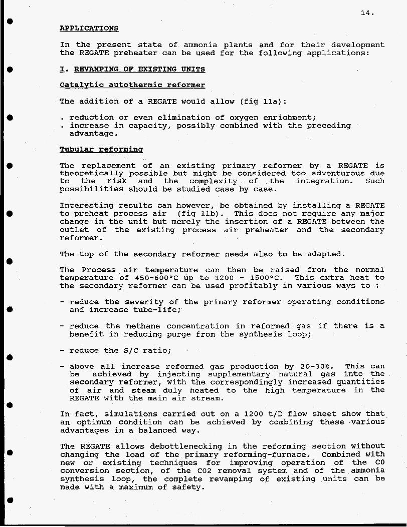
In the present sta,e of ammonia plants anc for their development the REGATE preheater can be used for the following applications:
- I. REVAMPING OF EXISTING UNITS Catalytic autothermic reformer
The addition of a REGATE would allow (fig lla):
. reduction or even elimination of oxygen enrichment; . increase in capacity, possibly combined with the preceding advantage.
Tubular reforminq
The replacement of an existing primary reformer by a REGATE is theoretically possible but might be considered too adventurous due to the risk and the complexity of the integration. Such possibilities should be studied case by case.
Interesting results can however, be obtained by installing a REGATE to preheat process air (fig llb). This does not require any major change in the unit but merely the insertion of a REGATE between the outlet of the existing process air preheater and the secondary reformer . The top of the secondary reformer needs also to be adapted.
The Process air temperature can then be raised from the normal temperature of 450-600°C up to 1200 - 15OOOC. This extra heat to the secondary reformer can be used profitably in various ways to :
- reduce the severity of the primary reformer operating conditions and increase tube-life;
- reduce the methane concentration in reformed gas if there is a benefit in reducing purge from the synthesis loop;
- reduce the S/C ratio; - above all increase reformed gas production by 20-30%. This can be achieved by injecting supplementary natural gas into the secondary reformer, with the correspondingly increased quantities of air and steam duly heated to the high temperature in the REGATE with the main air stream.
In fact, simulations carried out on a 1200 t/D flow sheet show that an optimum condition can be achieved by combining these -various advantages in a balanced way.
The REGATE allows debottlenecking in the reforming section without changing the load of the primary reforming-furnace. Combined with new or existing techniques for improving operation of the CO conversion section, of the C02 removal system and of the ammonia synthesis loop, the complete revamping of existing units can be made with a maximum of safety.

e
e
e
R E G A T E t A U T O T H E R M A L C A T A L Y T I C R E F O R M E R
I PROCESS I.C. p
B - F i g . I l o
~~ ~
R E G A T E t T U B U L A R R E F O R M E R
I- -7 : b
f i 9 . 111
R E G A T E t H E A T E X C H A N G E R E F O R M E R

16.
Exawles of revamping of existing reforming units Table I 1 compares an existing plant (Reference) with various cases of revamping with REGATE.
Reference : Typical a m n i a plant with : - primary reformer (800OC; S I C = 3.5; P = 33 bars a; NG = 95% CH4 1% C2H6, 4% N2) - H.T. and L.T. conversion (0,2% CO), C02 removal (0,1% COz) methanation - no molecular sieves or cryogenic treatment of syngas - no separation unit on purge gas (20% CH4 + A) - classical HP steam recovery (100 bar a) and power production by HP steam turbine (100 to 35 bar a) and MP
steam condensation turbines.
Case A1 : same as reference case, except : - - S l C down to 2.7. Results :
heating process air to 75OO0C by REGATE;
a) primary reformer heat duty down to 84% of reference case; b) slight increase of a m n i a production; c) 8% reduction of energy costs; reduction of direct and indirects maintenance costs (tube life).
Case A2 : same as case A1 except : - -
increasing heat duty to the value of reference case; additional process NG and steam to the primary reformer to balance the new heat duty (+ 19% of the value of. reference case).
Results : a) general heat duty of the primary reformer (radiant section and convertion section) almost the same as reference case; b) 8% reduction of energy costs; c) increase of the a m n i a production to 120% of the reference case.
Case B1 : same situation for primary reformer as for case A1 but : - - Results :
additional process NG directly to the secondary reformer <+ 30%) total process air plus corresponding additional process steam (for S/C = 2,7) to the REGATE
a) primary reformer heat duty down to 84x of Reference case; b) increase of a m n i a production (130% of reference case); c) 11% reduction of energy costs; reduction of direct and indirect maintenance costs (tube life).
Case 82 : same as B1 except : - increasing heat duty close to the value of reference case with additional process NC and steam to the
primary reformer to balance the new heat duty (+ 15% of the value of the reference case); proportional increase of the additional process NG to the secondary reformer and of the additional process steam to the REGATE.
Results : a) general heat duty of the primary reformer (radiant section and convection section) almost
-
the same as reference case; b) 11% reduction of energy costs; c) increase of the a m n i a production to 15oX of reference case.
PROFITS : the results on table I 1 are calculated for two situations : a) selling price of a m n i a equals the actual cost of production; b) selling price of a m n i a equals 110% of the actual cost of production.
They do not include the charges (depreciation and financial costs) of the new investments (REGATE and debottlenecking). A complete calcutation can only be done case by case for existing situation with additional optimization of the resu 1 t s . Table 11 gives only a first idea of the possibilities of the neu process.

0
0
e
0
a
a
TABLE 11, REVAMPING OF THE REFORMING SECTION OF AN EXISTING AMMONIA PLANT WITH REGATE
PROCESS CONDITIONS s/c
Process NC - t o prirn.reform.(kmol/s) - t o sec.reform. Process Steam - t o prirn.reform.(kmol/s) - t o REGATE I1
Process a i r - t o sec.reform. (kmol/s) - t o REGATE It
Primary Reformer - ou t le t temp. ("C)
CH4 (mol X )
- heat t o the tubes (KJ/s)
Regate - i n l e t temp. ("C) - ou t le t temp. ("C) - heat exchanged (KJ/s)
Secondary Reformer - out let temp. ("C)
CH4 (mol X )
NH3 product (kmol/s) (Mt/d)
ENERGY BALANCE (1) NG process (CJ/t NH3)
fue l p r im . ref. REGATE + gas turb.
E l e c t r i c i t y (Kwh/t NH3)
Total Energy (GJ/t NH3) equiv. (GJ/t NH3)(2)
COSTS Cost o f production N.G. (3) ($/t NH3) E l e c t r i c i t y (3) Miscellaneous
Fixed costs (4) ( A / t NH3)
Annual p r o f i t (5) (MMA) a) i f S.P. = 135,17 b/t b) i f S.P. = 135,17 + 10%
REFERENCE
3.5
0.4449
1.5106
0.5719
800 11.25
84840
( 534 1 ( 534 1
0
968 0.30
0.9401
22.42 8.86 0
31.28 36
0.42 31.70
81.01 2.16 2.00
85.17 50.00
135.17
0 5.9
A 1
2.7
0.4449
1.1653
0.5752
800 15.50
72715
498 1500
1961 0
1076 0.11
0.9135 1'3441
22.19 7.40 2.24
31 -83 - 98
-1.14 30.69
82.44 -5.88 2.00
78.56 49.48
128.04
3.1 9.2
A2
2.7
0.5278
0.6824
aoo 15.50
'84840
498 1500
23260
1076 0.11
1 -0837 (imJ
22.19 7.40 2.24
31.83 - 98
-1.14 30.69
82.44
2.00 78.56 41.72
-5.88
120.28
7.8 14.9
81
2.7
0.4449 0.1335
1.1653 0.3497
- 0.7433
aoo 15.50
7321 1
363 1500
45931
1023 0.23
1.1747 pEq
22.44 5.24 4.07
31.75 - 132
-1 -54 30.20
82.23 -7.92 2.00
76.31 38.46
114.77
11.6 19.3
2.7
0.5116 0.1535
1.3401 0.4021
0.8818
800 15.50
84200
363 1500
52820
1023 0.23
1.3509 p z r ]
22.44 5.24 4.07
31 -75 -132
-1.54 30.20
82.23 -7.92 2.00
76.31 33.45 ~
109.76
16.7 25.5
(1) GJ LHV / M t a m n i a . (2) 11620 KJ/kwh (3) U n i t cost : 2.75 $/MMBTu, LHV or 2.59 $/GJ LHV; 6 cents/kwh (4) Included catalyst, manpower, administration, maintenance, insurance, f inancial cost,
residual depreciation. BUT not included : depreciation and f inancial costs related t o the REGATE and revamping investment. a) Sel l ing pr ice = actual cost of production; production 330 d/y; (5)

1 8 .
- 11. NEW PLANTS
REGATE opens the way for AMMONIA PLANTS WITHOUT TUBULAR
(fig lla) OR ANY KIND OF NITROGEN SEPARATION UNITS. REFORMING AND WITHOUT I! CRYOGENIC OXYGEN-PRODUCTION UNIT
With the benefits of the thermodynamic cycle on the flue gas expansion, and with a rigorous energy integration, it is possible to design ammonia lines which are competitive with current lllow-energyll plants both in terms of investment and energy consumption.
A recent study on a low energy ammonia process (Ref 1) showed that :
(a) the primary reformer waste-heat section only preheats natural gas, reformer feed, process air and combustion air. No heat is supplied to the steam system;
(b) all economic heat available downstream the secondary reformer, from the shift converters and from the synthesis loop, is recovered for high-pressure superheated steam production (about 3t/t NH3);
process air compressor and the boiler feed-water pump. (c) this steam is sufficient to drive the syngas compressor, the
If the primary reformer is replaced by a REGATE, with the associated compressor, turbines and heat exchangers (fig. 12); the REGATE could feed the existing secondary reformer with air, steam and gas in such conditions that the exit gas from this Ilautothermic ref ormerll has the same temperature and composition as the low energy process. The results are given in table 111.

0 0 a a 0 e e e a
1 CONVENTIONAL "LOW ENERGY' I1000 MT NH3/d
N .6. PROCESS 5.25 G C 8 l . fLHV) r
tQ43 SYNTHESIS METHANATION PAIMARY co 2
mmiiu - - I I I I I I
I
t I I
I I I
REFORMER N.G. FUEL
1 .40 Gcal. (LHVI
P SYNGAS COrPR.TUR8.
REFRIG. t2J
I
I
STEAM IN) 0.10 Gc8l
N . G ,PROCESS 5 35 Cral I IHVI
AUTOTHEW. REFORMR I
8 POKER (4 408'kM or 1.13 6C8l.
SAME AS CONVENTIWAL LOW ENERGY 1 M T N H ,
i
In) 1 kwh a 2750 k c a l : 1 kg STEAM I40 kg/cm g : 380.C) - 757 kcal F i g .

2 0 .
~
TABLE 111. ENERGY BALANCE (GJ LHV/l Mt NH3 - 33OC) Capac. 1000 Mt NH3/d
1. Enerqv balance NG Process NG Fuel(Regate +
turbines) Steam export (1) Power import (1) Power export (Regate) (1)
2. Economics a) Unit costs :
- NG ($/MM3TU,LHV) - kWh (cents/kWh) b) Enerqy cost
J$/Mt NH3)
- NG process - NG fuel - Steam export - Electric power import/export
PRESENT "LOW ENERGY"
+ 21.98 GJ/Mt NH3 + 5.86 It I1
- 0.42 + 0.50 -
II
I1
27.92 II
2.75 4
57.3 15.3 -1.1
1.7
73.2
2.75 6
57.3 15.3 -1.1
2.6
74.1
(1) 1 kUh = 3.6 MJ; 1 kg steam (40 bar : 380°C) = 3.17 MJ.
1.75 6
36.5 9.7 -0.7
2.6
48.1
~~
"LOW ENERGY" + REGATE
+ 21.98 GJ/Mt NH3 11 + 10.34 I t
- 0.42 I'
+ 0.50 I'
- 4.73
27.67 It
2.75 4
57.3 27.0 -1.1
-14.6
68.6
2.75 6
57.3 27.0 -1.1
-21.8
61.4
1.75 6
36.5 17.2 -0.7
-21.8
31.2
Table I11 shows that with the REGATE it is possible to produce NH3 with a total energy consumption of 27.67 GJ (LHV) /Mt NH3 and that, by comparison with the present lllow energy" technology the advantage of the REGATE is particularly interesting when electricity is expensive and the natural gas is at low cost.

21.
MISCELLANEOUS REMARKS :
The REGATE process presents other advantages which cannot be developed extensively in this paper
1. A REGATE cycle may be combined with a prereformer with improved results.
2. To improve the operation of systems using the HEAT EXCHANGE REFORMER concept, it is possible to eliminate the thermal deficiency of this type of process by preheating process air to the secondary reformer to an appropriate temperature in a REGATE (Fig llc).
3 . It should be emphasized that the high temperature sections of the REGATE are refractory lined, and that the high pressure resistance of the equipment can be ensured by carbon steel working at moderate temperatures. There is, therefore, nothing to prevent synthesis gas generation at pressures of 80-100 bar. This would be impossible for tubular reforming. In view of recent technical innovations in the fields of CO conversion, C02 removal, and ammonia synthesis, there is no obstacle to the design of a MONO-PRESSURE AMMONIA PLANT, WITH COMPLETE ELIMINATION OF SYNTHESIS GAS COMPRESSION.
4. With a REGATE and in absence of a primary tubular reformer, heavier hydrocarbons and sulfur containing feeds can be much more easily reformed.
5. When all the ammonia production is to be converted into urea, carbon dioxide from the C02 removal section may be insufficient to balance the ammonia production. With REGATE, it is possible to recover carbon dioxide under pressure from the flue gas of the REGATE with practically no additional energy consumption.
6. With some minor modifications to meet safety requirements, REGATE can also be used to preheat at high temperatures gases containing H2 and CO. It can also be used as a cyclic catalytic reactor working at high pressure.
7. The investment cost of REGATE and associated turbines and heat exchangers is roughly 60 % of the investment of a primary reformer with waste heat recovery.
All these possibilities and many other arrangements of REGATE combined with various processes have been studied to demonstrate the economic validity of the system. Detailed calculations have yet to be done case by case on specific problems.
Ref 1. stAdvances in Ammonia Production Technology" by Dr.Ib. BYBKJAER / H. Topsoe AS Presented at 1990 FA1 Seminar New Dehli, India