stc group llc - cloud object storage | store & retrieve … · 2017-11-22 · stc group llc...
TRANSCRIPT
11STC GROUP LLC 480 Ruddiman Drive Avionics Addendum North Muskegon, Michigan 49445 E-1006-12 Rev -
STC GROUP LLC 480 RUDDIMAN DRIVE
NORTH MUSKEGON, MICHIGAN 49445-2783
DOCUMENT NUMBERE-1006-12 REVISION-
TRIO PRO PILOT AUTOPILOT AVIONICS ADDENDUM
DATE: Original Issue 15November, 2017
WRITTEN BY:
Paul Odum
APPROVED BY:
Jeff Ley

STC GROUP LLC Page 1 of 26 480 Ruddiman Drive Avionics Addendum North Muskegon, Michigan 49445 E-1006-12 Rev -
TRIO AP Provisions Installation Instructions Page 1
CONFIDENTIAL & PROPRIETARY. CONTAINS TRADE SECRETS PROTECTED BY THE UNIFORM TRADE SECRETS ACT AND OTHER PROPRIETARY INFORMATION, EXEMPT FROM PUBLIC DISCLOSURE UNDER FOIA [5 US Code sec. 552(b)(4)]
REVISIONS
Rev. Date: By: Approved By:
- 21 November 2017 Paul Odum Jeff ley
ER No: 1006
Section: Description
All Initial Release

STC GROUP LLC Page 2 of 26 480 Ruddiman Drive Avionics Addendum North Muskegon, Michigan 49445 E-1006-12 Rev -
TRIO AP Provisions Installation Instructions Page 2
CONFIDENTIAL & PROPRIETARY. CONTAINS TRADE SECRETS PROTECTED BY THE UNIFORM TRADE SECRETS ACT AND OTHER PROPRIETARY INFORMATION, EXEMPT FROM PUBLIC DISCLOSURE UNDER FOIA [5 US Code sec. 552(b)(4)]
TABLE OF CONTENTS
TABLE OF CONTENTS .................................................................................................. 2
LIST OF TABLES ............................................................................................................... 4
LIST OF FIGURES.............................................................................................................. 5
REFERENCES ..................................................................................................................... 6
ACRONYMS, ABBREVIATIONS, AND SYMBOLS ........................................................ 7
1.0 TRIO PRO PILOT AUTOPILOT AVIONICS ADDENDUM ................................. 8
2.0 GENERAL ............................................................................................................... 9
3.0 SERVO GAIN ADJUSTMENT – TRIO DOCUMENT NUMBER 170102 ............ 10
3.1 H NAV GAIN SETTING ........................................................................................ 10
3.2 RESTORE DEFAULTS PROCEDURE ............................................................... 10
3.3 GROUND CHECKS ............................................................................................... 11
3.4 INITIAL FLIGHT SETTINGS .............................................................................. 11
3.5 H NAV SERVO GAIN ADJUSTMENT ............................................................... 13
4.0 V NAV GAIN SETTING ........................................................................................ 15
4.1 ALTITUDE HOLD GAIN SETTING ................................................................... 15
4.2 V NAV SERVO GAIN ADJUSTMENT ................................................................ 16
4.3 VERTICAL SPEED GAIN SETTING .................................................................. 16
4.4 AIRSPEED GAIN SETTING................................................................................. 17
5.0 SERVO ROTATION DETERMINATION .......................................................... 18
5.1 ROLL SERVO ......................................................................................................... 18
5.2 PITCH SERVO ........................................................................................................ 19
5.3 INSTALLING THE SERVO REVERSAL JUMPER ......................................... 19
6.0 WIRING HARNESS INSTALLATION ............................................................... 20
6.1 ROLL SERVO HARNESS INSTALLATION ..................................................... 20
6.2 PITCH SERVO HARNESS INSTALLATION .................................................... 20
6.3 TRIO AUTOPILOT CONTROLLER .................................................................. 20
6.4 TRIO AUTOPILOT DATA CONNECTIONS ..................................................... 21

STC GROUP LLC Page 3 of 26 480 Ruddiman Drive Avionics Addendum North Muskegon, Michigan 49445 E-1006-12 Rev -
TRIO AP Provisions Installation Instructions Page 3
CONFIDENTIAL & PROPRIETARY. CONTAINS TRADE SECRETS PROTECTED BY THE UNIFORM TRADE SECRETS ACT AND OTHER PROPRIETARY INFORMATION, EXEMPT FROM PUBLIC DISCLOSURE UNDER FOIA [5 US Code sec. 552(b)(4)]
7.0 APPENDIX A - PRO PILOT SYSTEM WIRING DIAGRAM ............................... 22
8.0 QUESTIONS AND ANSWERS FROM THE FIELD .............................................. 23
STC GROUP LLC Page 4 of 26 480 Ruddiman Drive Avionics Addendum North Muskegon, Michigan 49445 E-1006-12 Rev -
TRIO AP Provisions Installation Instructions Page 4
CONFIDENTIAL & PROPRIETARY. CONTAINS TRADE SECRETS PROTECTED BY THE UNIFORM TRADE SECRETS ACT AND OTHER PROPRIETARY INFORMATION, EXEMPT FROM PUBLIC DISCLOSURE UNDER FOIA [5 US Code sec. 552(b)(4)]
LIST OF TABLES
No table of figures entries found.

STC GROUP LLC Page 5 of 26 480 Ruddiman Drive Avionics Addendum North Muskegon, Michigan 49445 E-1006-12 Rev -
TRIO AP Provisions Installation Instructions Page 5
CONFIDENTIAL & PROPRIETARY. CONTAINS TRADE SECRETS PROTECTED BY THE UNIFORM TRADE SECRETS ACT AND OTHER PROPRIETARY INFORMATION, EXEMPT FROM PUBLIC DISCLOSURE UNDER FOIA [5 US Code sec. 552(b)(4)]
LIST OF FIGURES
STC GROUP LLC Page 6 of 26 480 Ruddiman Drive Avionics Addendum North Muskegon, Michigan 49445 E-1006-12 Rev -
TRIO AP Provisions Installation Instructions Page 6
CONFIDENTIAL & PROPRIETARY. CONTAINS TRADE SECRETS PROTECTED BY THE UNIFORM TRADE SECRETS ACT AND OTHER PROPRIETARY INFORMATION, EXEMPT FROM PUBLIC DISCLOSURE UNDER FOIA [5 US Code sec. 552(b)(4)]
REFERENCES
The following documents form a part of this report. Unless a specific revision of one of these documents is specified, the revision in effect at the time of original issue of this document shall apply.
Trio Avionics Document Number 170102
Trio Avionics Document Number 171113
Trio Avionics Document Number41300007 Rev. 7
Other Data:
ER1006–STC GROUP LLC Program Engineering Record.

STC GROUP LLC Page 7 of 26 480 Ruddiman Drive Avionics Addendum North Muskegon, Michigan 49445 E-1006-12 Rev -
TRIO AP Provisions Installation Instructions Page 7
CONFIDENTIAL & PROPRIETARY. CONTAINS TRADE SECRETS PROTECTED BY THE UNIFORM TRADE SECRETS ACT AND OTHER PROPRIETARY INFORMATION, EXEMPT FROM PUBLIC DISCLOSURE UNDER FOIA [5 US Code sec. 552(b)(4)]
ACRONYMS, ABBREVIATIONS, AND SYMBOLS
Autopilot
Clip
C.G.
Trio Pro Pilot Autopilot
Part Number 1006237
Center of Gravity
ER Engineering Record
FAA Federal Aviation Administration
ICA Instructions for Continued Airworthiness
LH Left Hand
OEM Original Equipment Manufacturer
OTBD
PCS
Recover
Outboard
Pilot Controller Steering (Red) Button
Recover Button
RH
Servo
Right Hand
Trio Pro Pilot Gold Standard Servo
STC Supplemental Type Certificate
WS
Wing Station
STC GROUP LLC Page 8 of 26 480 Ruddiman Drive Avionics Addendum North Muskegon, Michigan 49445 E-1006-12 Rev -
TRIO AP Provisions Installation Instructions Page 8
CONFIDENTIAL & PROPRIETARY. CONTAINS TRADE SECRETS PROTECTED BY THE UNIFORM TRADE SECRETS ACT AND OTHER PROPRIETARY INFORMATION, EXEMPT FROM PUBLIC DISCLOSURE UNDER FOIA [5 US Code sec. 552(b)(4)]
1.0 TRIO PRO PILOT AUTOPILOT AVIONICS ADDENDUM
This document is provided to answer some commonly asked questions the we receive from the field. The Document will be updated frequently and should be considered as a “living” document. Check The STC Group LLC website frequently for revisions. www.thestcgroup.net
STC GROUP LLC Page 9 of 26 480 Ruddiman Drive Avionics Addendum North Muskegon, Michigan 49445 E-1006-12 Rev -
TRIO AP Provisions Installation Instructions Page 9
CONFIDENTIAL & PROPRIETARY. CONTAINS TRADE SECRETS PROTECTED BY THE UNIFORM TRADE SECRETS ACT AND OTHER PROPRIETARY INFORMATION, EXEMPT FROM PUBLIC DISCLOSURE UNDER FOIA [5 US Code sec. 552(b)(4)]
2.0 GENERAL
Thank you for your purchase of the TRIO Auto Pilot for your beloved aircraft. This document has been written to answer some of the commonly asked questions we receive from owners, mechanics, and avionics professionals. This document is intended as an addendum to the installation instructions for your aircraft type. The Avionics Addendum will ensure your installation is easy, ensures safety, and is professionally completed. Before you begin Read All Instructions. Call Jeff Ley at The STC Group LLC at (661) 524-6157 call/text/phone/VM if you have questions. You may also call chuck Busch at Trio Avionics, (619) 448-4619 if you have specific Trio Pro Pilot avionics integration questions. Drawings are denoted in the References section above and throughout these installation instructions. Illustrated Parts Catalogs on The STC Group LLC website at www.thestcgroup.net contain detailed parts drawings and Part Number listings.
STC GROUP LLC Page 10 of 26 480 Ruddiman Drive Avionics Addendum North Muskegon, Michigan 49445 E-1006-12 Rev -
TRIO AP Provisions Installation Instructions Page 10
CONFIDENTIAL & PROPRIETARY. CONTAINS TRADE SECRETS PROTECTED BY THE UNIFORM TRADE SECRETS ACT AND OTHER PROPRIETARY INFORMATION, EXEMPT FROM PUBLIC DISCLOSURE UNDER FOIA [5 US Code sec. 552(b)(4)]
3.0 SERVO GAIN ADJUSTMENT – TRIO DOCUMENT NUMBER 170102
3.1 H NAV GAIN SETTING
Note: If at any time during this procedure you get "lost" you can recycle power. If you change a setting and want to restore the defaults, you can accomplish a RESTORE DEFAULTS procedure as detailed below.
1. To ensure all autopilot (AP) gains and settings are initially at the factory defaults a RESTORE DEFAULTS will be the first item accomplished.
2. If you are certain that the defaults are correct you can skip this step. 3. If the RESTORE DEFAULTS is performed, you will need to reset the MINIMUM and
MAXIMUM airspeed thresholds as also detailed below after the gain setting procedures. Practice this procedure on the ground before flight so you won't get confused in the air.
3.2 RESTORE DEFAULTS PROCEDURE
Several of the variables used to optimize Pro Pilot are captured to EEPROM (nonvolatile memory) during initial setup. Further, tracking gains that are set for differing flight conditions are also maintained in system EEPROM.
On rare occasion these values may become corrupt if a power transient occurs during an EEPROM write procedure, or the pilot may inadvertently change settings that cause poor autopilot performance. The restore default procedure allows a quick method to restore all these values back to their factory settings.
It is good practice to record all the variable settings you change from the factory settings, so these may be replaced after the restore defaults procedure.
The RESTORE DEFAULTS procedure allows either one or both HNAV or VNAV parameters to be reset. To perform the RESTORE DEFAULTS procedure, perform the following steps:
STC GROUP LLC Page 11 of 26 480 Ruddiman Drive Avionics Addendum North Muskegon, Michigan 49445 E-1006-12 Rev -
TRIO AP Provisions Installation Instructions Page 11
CONFIDENTIAL & PROPRIETARY. CONTAINS TRADE SECRETS PROTECTED BY THE UNIFORM TRADE SECRETS ACT AND OTHER PROPRIETARY INFORMATION, EXEMPT FROM PUBLIC DISCLOSURE UNDER FOIA [5 US Code sec. 552(b)(4)]
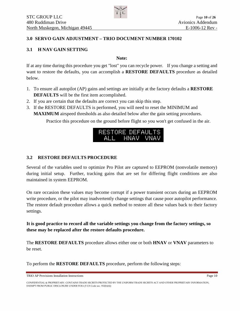
1. Enter the MAINTENANCE SETTINGS menus by pressing the ENCODER and VMODE buttons simultaneously, then select the RESTORE DEFAULTS display.
2. 01Press and release the H MODE button. The arrow will be placed at the "ALL" setting field. Press the encoder knob to activate the restore. All lower display parameters will flash when the function is complete.
3. If it is desired to reset only the H NAV defaults, Press and release the H MODE button to position the cursor adjacent to HNAV. Press the ENCODER knob to activate. The HNAV display will flash when the function is complete.
4. If it is desired to reset only the VNAV defaults, Press and release the H MODE button again to position the cursor adjacent to VNAV. Press the encoder to activate. The VNAV display will flash when the function is complete.
5. Press the H MODE button until the right arrow is absent from the display. 6. Cycle power on the autopilot to exit the maintenance screens. The RESTORE DEFAULTS procedure is complete and the encoder can now be used to select another menu screen.
3.3 GROUND CHECKS
1. Check servo actuation, slip clutch operation and servo disconnect / release
3.4 INITIAL FLIGHT SETTINGS
1. Be sure to turn the AP on after engine start to stabilize the internal gyro before flight. Leave the autopilot ON unless otherwise noted
Note:
It is important to adjust the CRS gain prior to adjusting the TRK gain. When the CRS gain has be satisfactorily adjusted, do not change it when adjusting the TRK gain. 2. Place the AP in the CRS mode and engage the servo. Let the aircraft track stabilize. 3. Enter the MAINTENANCE SETTINGS menus by pressing the ENCODER and VMODE
buttons simultaneously, then select the SET H NAV GAINS screen. 4. If roll is oscillating adjust the CRS setting UP or DOWN to minimize.

STC GROUP LLC Page 12 of 26 480 Ruddiman Drive Avionics Addendum North Muskegon, Michigan 49445 E-1006-12 Rev -
TRIO AP Provisions Installation Instructions Page 12
CONFIDENTIAL & PROPRIETARY. CONTAINS TRADE SECRETS PROTECTED BY THE UNIFORM TRADE SECRETS ACT AND OTHER PROPRIETARY INFORMATION, EXEMPT FROM PUBLIC DISCLOSURE UNDER FOIA [5 US Code sec. 552(b)(4)]
5. If satisfactory tracking is obtained, switch the AP to the TRK mode and optimize the tracking using the TRK setting (see Section 3.5).
6. If satisfactory performance cannot be obtained return the settings to the factory defaults (TRK = 3, CRS = 3, PI = 9) and proceed to the HNAV SERVO GAIN ADJUSTMENT below.

STC GROUP LLC Page 13 of 26 480 Ruddiman Drive Avionics Addendum North Muskegon, Michigan 49445 E-1006-12 Rev -
TRIO AP Provisions Installation Instructions Page 13
CONFIDENTIAL & PROPRIETARY. CONTAINS TRADE SECRETS PROTECTED BY THE UNIFORM TRADE SECRETS ACT AND OTHER PROPRIETARY INFORMATION, EXEMPT FROM PUBLIC DISCLOSURE UNDER FOIA [5 US Code sec. 552(b)(4)]
3.5 H NAV SERVO GAIN ADJUSTMENT
1. Select the CRS mode with the SERVO ON and stabilize on a ground track. There may be some oscillation at this point and it should be ignored.
2. Select the MAINTENANCE SCREENS and sequence to the SET SERVO GAINS menu. 3. Press the H MODE button until an arrow is in front of the HNAV gain. 4. Use the ENCODER to decrease or increase the gain in steps of 4 units until the oscillation stops
or is minimized. a. You can fine tune the gain by increasing or decreasing the gain setting by one step after
bracketing the gain using 4 units. b. A setting that is too low will cause the AP to stabilize on a course a degree or more on one
side of the selected course, or may cause a very long “hunting” from one side of the selected course to the other of more than two degrees.
c. A setting that is too high will cause an oscillation of a shorter period across the selected course of two degrees or more.
d. The setting is optimized when the selected course is maintained within +/- 1 degree in a very slow oscillatory fashion.
Note: The period of this oscillation should be greater than one (1) minute.
e. Increase or decrease the gain to suit your personal preference. f. The autopilot may track perfectly for several minutes, then wander - 1 degree, back to zero
for a minute, etc. Once this is achieved you can repeat the CRS gain procedure to further refine the gains.
g. Exit the MAINTENANCE SCREENS menu by pressing and holding the ENCODER until the normal navigation screens appear.
Note: The TRK gain is not used when GPSS is providing lateral navigation. If GPSS is being used for lateral navigation you will need to enter a track offset when using the TRK mode on the autopilot. This disables the GPSS input and forces the autopilot to use the serial data stream. 5. Select the TRK mode.
a. If GPSS is active enter a left or right 0.10 track offset (press and turn the ENCODER in the TRK mode).
b. Repeat steps 2, 3, and 4 until the arrow is pointing at the TRK gain. c. Minimize the track error (XTK) by adjusting the TRK gain. d. A setting that is too high will cause a slow return to the center line or stabilization at an offset. e. A setting that is too low will cause oscillation back and forth across the DTK line in excess of 0.02
miles.
STC GROUP LLC Page 14 of 26 480 Ruddiman Drive Avionics Addendum North Muskegon, Michigan 49445 E-1006-12 Rev -
TRIO AP Provisions Installation Instructions Page 14
CONFIDENTIAL & PROPRIETARY. CONTAINS TRADE SECRETS PROTECTED BY THE UNIFORM TRADE SECRETS ACT AND OTHER PROPRIETARY INFORMATION, EXEMPT FROM PUBLIC DISCLOSURE UNDER FOIA [5 US Code sec. 552(b)(4)]
6. The PI (Pull In) is usually OK. a. If the intercept after a switch from the INT mode to the TRK mode is too aggressive, lower
this setting. b. If the intercept is “lazy” raise this setting.
STC GROUP LLC Page 15 of 26 480 Ruddiman Drive Avionics Addendum North Muskegon, Michigan 49445 E-1006-12 Rev -
TRIO AP Provisions Installation Instructions Page 15
CONFIDENTIAL & PROPRIETARY. CONTAINS TRADE SECRETS PROTECTED BY THE UNIFORM TRADE SECRETS ACT AND OTHER PROPRIETARY INFORMATION, EXEMPT FROM PUBLIC DISCLOSURE UNDER FOIA [5 US Code sec. 552(b)(4)]
4.0 V NAV GAIN SETTING
This procedure is a method that should be used to set the Altitude Hold (AH) Vertical Speed (VS) and Airspeed (AS) gains.
Note:
It is recommended that the auto trim be disabled during these procedures. This can be accomplished by minimizing the trim speed setting in the MAINTENANCE SETTING screens
4.1 ALTITUDE HOLD GAIN SETTING
1. Perform all initial ground checks prior to this test. 2. Place the aircraft in a stable pitch trim neutral cruise configuration. 3. Engage the Altitude Hold, AH, mode by pressing the VNAV button. 4. If there is any oscillation, enter the MAINTENANCE SETTINGS menus as described in
Section 3.4 above and select the VNAV GAIN SETS display page. 5. Press the HMODE button to place the arrow next to the AH gain setting. 6. Increase the gain setting five points and evaluate the tracking performance. 7. If the performance is degraded, lower the gain setting 10 points. 8. If the performance improves or there is no noticeable change, increase or decrease the setting an
additional five points as required. 9. Continue this process until an optimum value is reached.
Note:
If satisfactory performance cannot be obtained return the settings to the Factory Defaults, as described in Section 3.2 above, and proceed to Section 4.2, VNAV SERVO GAIN Adjustment below.
10. Further gain refinement can be achieved as follows: a. Place the aircraft in a pitch neutral configuration and engage the Altitude Hold, AH, mode. b. Engage the left or right AUTO 180 MODE (press and hold either the VNAV or HNAV
button for 3 seconds. c. While entering the 180-degree turn, observe altitude loss. d. If the altitude loss is greater than about 20 to 40 feet, raise the Altitude Hold, AH, gain by 5
points and repeat this process until the altitude loss is within 20 to 40 feet. e. If the altitude loss was less than 30 to 40 feet, the gain may be too high. f. If the gain is too high you may want to decrease the gain setting and note that the
recommended altitude loss is observed during the turn.
STC GROUP LLC Page 16 of 26 480 Ruddiman Drive Avionics Addendum North Muskegon, Michigan 49445 E-1006-12 Rev -
TRIO AP Provisions Installation Instructions Page 16
CONFIDENTIAL & PROPRIETARY. CONTAINS TRADE SECRETS PROTECTED BY THE UNIFORM TRADE SECRETS ACT AND OTHER PROPRIETARY INFORMATION, EXEMPT FROM PUBLIC DISCLOSURE UNDER FOIA [5 US Code sec. 552(b)(4)]
4.2 V NAV SERVO GAIN ADJUSTMENT
1. Select the CRS mode with the SERVO ON and stabilize on a specific ground track. 2. Select the MAINTENANCE SCREENS and sequence to the SET SERVO GAINS menu. 3. Press the H MODE button until an arrow is in front of the VNAV gain setting. 4. Use the ENCODER to decrease or increase the gain in steps of 4 units until the oscillation stops
or is minimized. 5. You can fine tune the gain by increasing or decreasing by one step after bracketing the gain
using 4 units. a. A setting that is too will cause the autopilot to fail to hold the selected altitude. b. The autopilot may oscillate more than 20 feet above or below the selected altitude. c. A setting that is too high will cause an oscillation of a shorter period or result in a divergent
altitude situation. d. The setting is optimized when the selected altitude is maintained within 20 to 30 feet in
smooth air without noticeable oscillation wander - 1 degree, back to zero for a minute, etc. e. Once the settings are close you can go back to the Altitude Hold, AH, gain setting in Section
4.1.5 above to refine the gains. 6. Exit the MAINTENANCE SCREENS menu by pressing and holding the ENCODER until the
normal navigation screens appear.
4.3 VERTICAL SPEED GAIN SETTING
1. Perform all initial ground checks and verify that the servo direction settings are correct. 2. Place the aircraft in a stable pitch trim neural cruise configuration. 3. Select the VS mode. 4. Rotate the ENCODER to set a 500 FPM climb rate. 5. Select VNAV on the autopilot controller and activate the climb by pressing the ENCODER
knob. 6. The VS LED should be on steady orange
Note:
The following steps assume the aircraft is properly trimmed for the climb rate selected. The aircraft should be manually trimmed for the selected climb rate. Failure to maintain a relatively good trim may cause the autopilot control system to exhibit a slight “bucking” motion during the climb. 7. The aircraft should settle into a 500FPM rate of climb within about 10 seconds. 8. If you observe significant deviation in smooth air from the selected climb rate perform the
remaining steps.

STC GROUP LLC Page 17 of 26 480 Ruddiman Drive Avionics Addendum North Muskegon, Michigan 49445 E-1006-12 Rev -
TRIO AP Provisions Installation Instructions Page 17
CONFIDENTIAL & PROPRIETARY. CONTAINS TRADE SECRETS PROTECTED BY THE UNIFORM TRADE SECRETS ACT AND OTHER PROPRIETARY INFORMATION, EXEMPT FROM PUBLIC DISCLOSURE UNDER FOIA [5 US Code sec. 552(b)(4)]
9. If there is excess oscillation or the vertical rate is not achieving the selected value, enter the MAINTENANCE SETTINGS menus and select the VNAV GAIN SETS display page
10. Press the HMODE button to select the VS gain setting. 11. Adjust the gain setting five points up and evaluate the tracking performance. If the performance
is degraded, readjust the gain setting 10 points lower. If the performance improves or there is no noticeable change, increase / decrease the setting an additional five points. Continue this process until an optimum value is reached.
4.4 AIRSPEED GAIN SETTING
Note:
The aircraft vertical when entering the Airspeed, AS, mode must be greater than +/- 200FPM. If the vertical rate is less than this value, the system will revert to the Altitude Hold, AH, mode on release of the servo disconnect switch.
1. Perform all initial ground checks and verify servo direction settings prior to this test. 2. Place the aircraft in a stable pitch neural cruise configuration 3. Engage the Altitude Hold, AH, mode 4. Press and hold the remote servo disconnect (PCS) switch. 5. The VNAV LED will now flash. 6. Place the aircraft in either a climb or descent and release PCS switch at the desired airspeed
Note:
The following steps assume the aircraft is properly trimmed for the selected airspeed. The aircraft should be manually trimmed for airspeed.
7. The aircraft should track the desired airspeed within 2 or 3 knots in smooth air. If there is significant deviation from the selected airspeed, perform the remaining steps.
8. Enter the MAINTENANCE SETTINGS menus and select the VNAV GAIN SETS display page.
9. Press the HMODE button to select the AS gain setting. 10. Increase the gain setting five points and evaluate the tracking performance. 11. If the performance is degraded, decrease the gain setting 10 points. 12. If performance improves or there is no noticeable change, increase or decrease the setting an
additional five points. 13. Continue this process until an optimum value is reached. 14. Once the airspeed gain is bracketed you can increment or decrement one unit at a time to fine
tune the gains.
STC GROUP LLC Page 18 of 26 480 Ruddiman Drive Avionics Addendum North Muskegon, Michigan 49445 E-1006-12 Rev -
TRIO AP Provisions Installation Instructions Page 18
CONFIDENTIAL & PROPRIETARY. CONTAINS TRADE SECRETS PROTECTED BY THE UNIFORM TRADE SECRETS ACT AND OTHER PROPRIETARY INFORMATION, EXEMPT FROM PUBLIC DISCLOSURE UNDER FOIA [5 US Code sec. 552(b)(4)]
5.0 SERVO ROTATION DETERMINATION
Note:
If this is a prototype installation. The final servo direction, CW (clockwise), or CCW (counter clockwise) is determined as part of the installation engineering process. The servos as shipped are set for CW operation. In the event the servos must be configured for CCW rotation an internal jumper provided on the servo Printed Circuit Board (PCB) needs to be fully installed. A spare label provided on the servo cover must be installed over the existing label. It easier to insert the jumper on the PCB before the servo is installed. You must read and understand paragraphs 1 and 2 before installing the servo. Based on design you can determine if the servo needs to be changed to a CCW rotation prior to actual installation. If you need assistance please call Chuck Busch at Trio Avionics, 619 448 4619 or Jeff Ley at The STC Group, 818 266 4369. Clockwise operation is specified if the servo rotation is CW as viewed when facing the servo hub/crankarm assembly. To determine the servo rotation direction for this airplane, perform the following procedure:
5.1 ROLL SERVO
1. If right aileron is input manually on the control yoke (or stick) and the servo rotates in a CW direction, then servo CW drive is required.
2. In this case the PCB jumper is not installed (and not required) and the servo PN is 30000000. 3. This is the configuration (p/n 30000000) that the servo is shipped. The spare label provided on
the cover should be discarded. 4. If right aileron is input and the servo rotates in a CCW direction, then servo CCW drive is
required. 5. In this case the jumper must be installed on the PCB and the servo PN is 31000000. 6. The spare label provided must be placed on the servo cover over the existing label. 7. The procedure for installing the jumper is provided in paragraph 5.3 below.
STC GROUP LLC Page 19 of 26 480 Ruddiman Drive Avionics Addendum North Muskegon, Michigan 49445 E-1006-12 Rev -
TRIO AP Provisions Installation Instructions Page 19
CONFIDENTIAL & PROPRIETARY. CONTAINS TRADE SECRETS PROTECTED BY THE UNIFORM TRADE SECRETS ACT AND OTHER PROPRIETARY INFORMATION, EXEMPT FROM PUBLIC DISCLOSURE UNDER FOIA [5 US Code sec. 552(b)(4)]
5.2 PITCH SERVO
1. If an elevator command is manually input for pitch UP (to make the airplane climb) and the servo rotates in a CW direction a servo CW drive is required.
2. The PCB jumper is not required. The servo PN is 30000000. 3. CW is the configuration that the servo is shipped. 4. The spare label provided on the cover should be discarded 5. If an elevator command is manually input for pitch UP (to make the airplane climb) and the
servo rotates in a CCW direction a servo CCW drive is required. 6. The jumper will need to be installed. 7. The servo PN is 31000000. 8. The spare label provided must be placed on the servo cover over the existing label. 9. The procedure for installing the jumper is provided in paragraph 5.3 below.
5.3 INSTALLING THE SERVO REVERSAL JUMPER
Note: Exercise caution when performing the following procedure.
1. Carefully remove the servo cover. 2. Locate the jumper on the PCB directly behind the DB-9 connector on the PCB. 3. The jumper is located on one of the jumper pins, not across both pins. 4. Using a small pair of needle nose pliers or similar tool remove the jumper from the pin on which
it is installed by pulling it straight up off the PCB. 5. Relocate the jumper over both the pins on the PCB and install it by pushing it down over both
jumper pins. 6. Reinstall the servo cover. 7. Place the PN 31000000 label over the existing 30000000label.

STC GROUP LLC Page 20 of 26 480 Ruddiman Drive Avionics Addendum North Muskegon, Michigan 49445 E-1006-12 Rev -
TRIO AP Provisions Installation Instructions Page 20
CONFIDENTIAL & PROPRIETARY. CONTAINS TRADE SECRETS PROTECTED BY THE UNIFORM TRADE SECRETS ACT AND OTHER PROPRIETARY INFORMATION, EXEMPT FROM PUBLIC DISCLOSURE UNDER FOIA [5 US Code sec. 552(b)(4)]
6.0 WIRING HARNESS INSTALLATION
NOTE Prior to plugging harness DB9 or DB37 into servos or autopilot control perform a full power, ground, and data test on the harness by ringing the wires from plug to plug using PRO PILOT WIRING HARNESS DWG 41300007. Refer to Appendix A,
The Trio Avionics CD, included with the autopilot kit, and the Trio website have links to DWG 41300007. Call Trio Avionics at 1 619-448-4619 if you have additional questions or need assistance.
6.1 ROLL SERVO HARNESS INSTALLATION
1. Remove interior trim panels on cockpit passenger side 2. Remove existing Cessna factory autopilot wiring and set aside for weighing if so equipped. 3. Route Trio Harness Roll servo wiring along same path and using the same clamps as factory
autopilot wiring. 4. Take care to protect harness pins at end of harness. 5. Terminate supplied DB9 connector per Trio diagram. 6. Attach DB 9 connector to Trio Roll Servo. 7. Secure harness cable end at the servo end with supplied clamp or equivalent.
6.2 PITCH SERVO HARNESS INSTALLATION 1. Remove co-pilot seat 2. Route Trio Harness Pitch servo wiring under cockpit floor taking care to secure away from
other aircraft wiring and moving components. 3. Route harness to Trio Pitch Servo location. 4. Take care to protect harness pins at end of harness. 5. Terminate supplied DB9 connector per Trio diagram. 6. Attach DB 9 connector to Trio Roll Servo. 7. Secure harness cable end at the servo end with supplied clamp or equivalent.
6.3 TRIO AUTOPILOT CONTROLLER 1. The Trio autopilot controller is ordered in Panel Mount or Instrument Mount versions. 2. Install the controller using best practices in either panel or hole locations. Refer to AC 43-13
for this step and all following steps. 3. Install the supplied 5 ampere circuit breakers within easy reach of the pilot and label. 4. If a Panel Mount unit is ordered install the supplied power switch and label. 5. Terminate supplied DB37 connector per the Trio drawing 41300007.

STC GROUP LLC Page 21 of 26 480 Ruddiman Drive Avionics Addendum North Muskegon, Michigan 49445 E-1006-12 Rev -
TRIO AP Provisions Installation Instructions Page 21
CONFIDENTIAL & PROPRIETARY. CONTAINS TRADE SECRETS PROTECTED BY THE UNIFORM TRADE SECRETS ACT AND OTHER PROPRIETARY INFORMATION, EXEMPT FROM PUBLIC DISCLOSURE UNDER FOIA [5 US Code sec. 552(b)(4)]
6. Terminate wiring with aircraft GPS or handheld. 7. If ARINC 429 is available from GPS terminate ARINC 429 connections. 8. Install the supplied PCS button on the left side of the pilots control yoke and label PCS. 9. Install Recover button in an available convenient location within easy reach of the pilot and
label AP Recover. 10. Ensure that the analog alarm out is connected to the un-switched audio input on the Audio
Panel. Note:
If your audio panel does not have un-switched audio input, attach the audio leads to the phone input of your intercom.
6.4 TRIO AUTOPILOT DATA CONNECTIONS
1. For the RS-232 connection set the output at the GPS unit to "Aviation w/ no altitude" or NMEA 0183 OUT.
2. If your aircraft is equipped with a GPS that has ARINC 429, set unit to output "GAMA" Low Speed.
3. Prior to making the connections to the GPS unit in the aircraft determine what else is connected. It may be necessary to parallel the connections. If parallel connections are required, verify that the lines you are connecting to use, or can use, the same data format that is required. Both the RS-232 and the ARINC 429 can be paralleled with like connections.
STC GROUP LLC Page 22 of 26 480 Ruddiman Drive Avionics Addendum North Muskegon, Michigan 49445 E-1006-12 Rev -
TRIO AP Provisions Installation Instructions Page 22
CONFIDENTIAL & PROPRIETARY. CONTAINS TRADE SECRETS PROTECTED BY THE UNIFORM TRADE SECRETS ACT AND OTHER PROPRIETARY INFORMATION, EXEMPT FROM PUBLIC DISCLOSURE UNDER FOIA [5 US Code sec. 552(b)(4)]
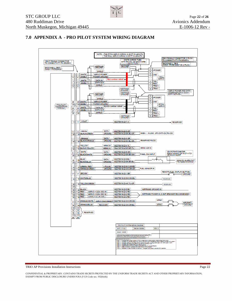
7.0 APPENDIX A - PRO PILOT SYSTEM WIRING DIAGRAM

STC GROUP LLC Page 23 of 26 480 Ruddiman Drive Avionics Addendum North Muskegon, Michigan 49445 E-1006-12 Rev -
TRIO AP Provisions Installation Instructions Page 23
CONFIDENTIAL & PROPRIETARY. CONTAINS TRADE SECRETS PROTECTED BY THE UNIFORM TRADE SECRETS ACT AND OTHER PROPRIETARY INFORMATION, EXEMPT FROM PUBLIC DISCLOSURE UNDER FOIA [5 US Code sec. 552(b)(4)]
8.0 QUESTIONS AND ANSWERS FROM THE FIELD
ARINC 429 and RS-232
We use both signals for the various modes in the autopilot. The RS-232 AVIATION format needs to be present at pin 6 of the autopilot.
The autopilot lateral gains (TRK, CRS, PI and HNAV SERVO GAIN) should always be accomplished before using the GPSS as the lateral navigation source. All these baseline gain settings use the serial data, no the GPSS input. In our field experience if the tracking is SAT after tuning the TRK, CRS, PI and HNAV SERVO GAIN using the serial link, the GPSS will work without any adjustment of the servo gain. In other words, the serial tuning is a baseline for using GPSS.
The TRK gain is only effective when using the serial link as the lateral navigation source. However, if the GPSS is active, GPSS automatically becomes the selected lateral navigation source in the TRK mode. GPSS provides a simple bank left - bank right control signal to the autopilot. There is no way to manipulate this input to do CRS, or INT functions so these two modes only use the serial inputs data. The TRK mode GPSS tracking tuning is only a function of the HNAV servo gain, nothing else. In order to force the serial data as the lateral tracking source in the TRK mode you can use the track offset function. Whenever there is a track offset lateral navigation is forced to the serial data. In this configuration you can adjust the TRK gain. The attached graphic helps explain the implementation
CRS Mode
Q1 We didn't saw any interface to the Directional Gyro for the Heading bug. I guest this is built-in in the autopilot computer/control head. Please confirm.
A1 The CRS mode on the autopilot allows flying vectors using GPS as the reference.
Q2 Previous autopilot was connected to the Turn Coordinator (only). Is the Trio autopilot require an external Rate and/or attitude information? ..or is the signal also built-in in the autopilot computer/control head? Please confirm. Thanks,
A2 All necessary equipment except the GPS is contained within the Pro Pilot system. No connections to any other external equipment is required.
STC GROUP LLC Page 24 of 26 480 Ruddiman Drive Avionics Addendum North Muskegon, Michigan 49445 E-1006-12 Rev -
TRIO AP Provisions Installation Instructions Page 24
CONFIDENTIAL & PROPRIETARY. CONTAINS TRADE SECRETS PROTECTED BY THE UNIFORM TRADE SECRETS ACT AND OTHER PROPRIETARY INFORMATION, EXEMPT FROM PUBLIC DISCLOSURE UNDER FOIA [5 US Code sec. 552(b)(4)]
Trim UP / DN LED’s
The auto trim doesn't work quite the way you describe. The control head generates the data that is sent to the servo to generate the bi-polar trim motor drive signals.
In theory you could use a set of LEDs driven by pins 1 and 6 of the pitch servo to give you a trim indication. These pulses are of a variable duration (10ms - 990ms / sec) depending on the settings used in the trim drive setups. Since you would be driving LEDs rather than a trim motor you could set the trim pulse width to a maximum setting, so the LED would be readable.
These bi-polar signals work as follows:
NO TRIM REQD - Both pins 1/6 at ground potential
TRIM UP Pin 1 at ground, pin 6 at airframe power*
TRIM DN Pin 6 at ground, pin 1 at airframe power*
* these can be reversed in the trim drive setups.
Depending on the airframe voltage and the LED current drive requirements you would have to select a current limiting resistor in series with the LED to control the LED current
A basic description other circuit would be:
Pin 1(6) --------->current limiting resistor---->LED anode-------LED cathode------------>ground
We have never used the outputs like this so I cannot say with certainty they would satisfy your requirements.
Automatic Trim
The trio pitch servo generates a bi-polar DC trim motor drive signal on pins 1 and 6 of the DB-9 connector. The auto trim capability is in place when the system is sold. The problem with implementation is regulatory, not technical.
The STC group has had discussions with the FAA regarding implementing auto trim and the FAA indicated to do this would require opening up the existing STC to add this feature. This process would likely result in a complete re-evaluation of the current STC. This would be a very timely and costly process. I believe The STC Group can confirm that are working with the FAA to come up with a plan to do the auto trim implementation without opening the existing STC.
There is some additional information on the auto trim implementation available on the Trio Website Experimental Manual V 3.8. Adding this feature to a certified airframe is not allowable under the current STC.
STC GROUP LLC Page 25 of 26 480 Ruddiman Drive Avionics Addendum North Muskegon, Michigan 49445 E-1006-12 Rev -
TRIO AP Provisions Installation Instructions Page 25
CONFIDENTIAL & PROPRIETARY. CONTAINS TRADE SECRETS PROTECTED BY THE UNIFORM TRADE SECRETS ACT AND OTHER PROPRIETARY INFORMATION, EXEMPT FROM PUBLIC DISCLOSURE UNDER FOIA [5 US Code sec. 552(b)(4)]
Garmin GNC 300XL
The GNC 300 will in fact drive the lateral navigation aspects of the autopilot. Works fine for that function. The GNC 300 being a pre-WAAS design will not generate the data we used for the IFR GPS guidance function. A receiver capable of providing the data required for full autopilot GPS approach capability would be the Garmin 4XXW, 5XXW, GTN6XX, GTN7XX, or similar Avidyne products.
Stratus
The WAAS GPS receiver typically used to qualify the Stratus probably is not sufficient for full functionality of the autopilot. The autopilot approach capability uses a certified WAAS enabled panel mount that can generate the digital guidance data (ARINC 429 GAMA 117G) required for GPS approaches.
I do not have the Stratus specifications or installation documentation, so I cannot say for sure, but I'm about 99.9% certain it will not drive the autopilot.