stc simulator.pdf
TRANSCRIPT

ABSTRACT
Design of a Solar Thermal Collector Simulator
Kirk G. Bolton, M.S.
Mentor: Ian A. Gravagne, Ph.D.
The recent increased interest in renewable energy has created a need for research
in the area of solar technology. This has brought about many new opportunities for
universities and research centers to build upon existing technology or develop new
strategies for handling how energy systems function. Both avenues of research could
require an experimental test bench to verify and quantify results.
This thesis outlines the design and testing of a simulator for a small solar thermal
collector array that can be used in a laboratory configuration to test other parts of a solar
thermal collector system. The simulator will be able to repeatedly produce given output
power conditions so that other components in a typical solar thermal system can be tested
with greater reliability.
Page bearing signatures is kept on file in the Graduate School.
Design of a Solar Thermal Collector
by
Kirk G. Bolton, B.S.
A Thesis
Approved by the Department of Electrical and Computer Engineering
___________________________________ Kwang Y. Lee, Ph.D., Chairperson
Submitted to the Graduate Faculty of
Baylor University in Partial Fulfillment of the Requirements for the Degree
of Master of Science in Electrical and Computer Engineering
Approved by the Thesis Committee
___________________________________ Ian A. Gravagne, Ph.D., Chairperson
___________________________________
Kenneth W. Van Treuren, Ph.D.
___________________________________ John M. Davis, Ph.D.
Accepted by the Graduate School May 2009
___________________________________
J. Larry Lyon, Ph.D., Dean

Copyright © 2009 by Kirk G. Bolton
All rights reserved

iii
TABLE OF CONTENTS
LIST OF FIGURES v LIST OF TABLES vii LIST OF ABBREVIATIONS ix ACKNOWLEDGMENTS x CHAPTER ONE 1
Introduction 1 Purpose of this Project 1 System Description 2 Chapter Descriptions 2
CHAPTER TWO 4
Theory behind the Project 4 Usefulness of the Project 4 Solar Feasibility in Central Texas 4
CHAPTER THREE 9
Hardware Overview 9 Hardware Modification 9 Control Board 9 Heating Elements 10 Thermistors 11 Power Control 13 Safety Relays 15 Status LEDs 15 Flow Meter Inputs 16 Auxiliary ADC Inputs 16 Power Supply 17 Microcontroller Board 17
CHAPTER FOUR 19
Software Overview 19 Microcontroller Board 19 Power Control 20 ADC Handling 22 Temperature Reporting 22 Flow Meter Reading 24
iv
UDP Communications 25 Error Handling 26 TRIAC Firing Delay 26 External Control Program 27
CHAPTER FIVE 28
Test Results and Verification 28 System Performance Goals 28 Repeatability Test Results 29 Accuracy Test Results 35 Test Conclusions 36
APPENDICES 38
A-User’s Manual 39 Interfacing with the STCS 39 Initial Set-up of the STCS 43 Maintaining the STCS 45
B-Average Power Output versus TRIAC Delay 47 C-Solar Thermal Collector Simulator Communication Standards 51 DAvailable Insolation and Power 56
Available Insolation 56 Available Power 58
E-Conceptual Analysis and Feasibility Study 61 Conceptual Analysis 61 Feasibility Study 66
F-Uncertainty Calculations 72 Method Used to Find Uncertainties 72 Calculations and Data 76
G-Control Board Design Information 81 Board Layout 81 Board Schematic 82 Parts List 83
H-Source Code 84 Files Included in Project 84 mxwebsrvr.c 85 compiler.h 107 projdefs.h 120
BIBLIOGRAPHY 139
v
LIST OF FIGURES
Figure 1. Basic solar thermal configuration. 1
Figure 2. Total insolation on a tilted flat plate collector. 5
Figure 3. Payback period in terms of years. 7
Figure 4. System connection overview. 10
Figure 5. Original thermistor response curve. 12
Figure 6. New thermistor response curve. 12
Figure 7. ADC count versus temperature response curve. 14
Figure 8. Auxiliary user supplied inputs. 17
Figure 9. STCS hardware. 18
Figure 10. Modtronix SBC65EC. 20
Figure 11. Software system overview. 21
Figure 12. Sample temperature versus ADC count response curve. 22
Figure 13. Output power in Watts from trial one. 30
Figure 14. Output power in Watts from trial two. 31
Figure 15. Output power in Watts from trial three. 32
Figure 16. Output power in Watts from trial four. 33
Figure 17. Output power in Watts from trial five. 34
Figure 18. Output from all five repeatability tests overlaid. 35
Figure 19. Output power in Watts from full day test. 37
Figure A.1. A request for status update command being transmitted to the STCS. 42
vi
Figure A.2. A heater power level command being transmitted to the STCS. 42
Figure A.3. A sample status update received from the STCS. 42
Figure A.4. A sample error code being received from the STCS. 42
Figure A.5. Oscilloscope probes connected across heating element wires. 43
Figure A.6. Oscilloscope screen showing 4.16 ms firing delay. 44
Figure A.7. Firing delay adjustment buttons. 45
Figure A.8. Fluid level sensor screws. 46
Figure B.1. Average power versus TRIAC delay. 48
Figure C.1. Firing delay. 53
Figure E.1. TRNSYS project layout. 67
Figure G.1. STCS control board layout. 81
Figure G.2. STCS control board schematic. 82
vii
LIST OF TABLES
Table 1. Equations used by the microcontroller for calculating reported temperatures. 23
Table 2. Equations for calculating temperature of auxiliary inputs. 24
Table A.1. ASCII strings transmitted to the STCS. 40
Table A.2. ASCII strings received from the STCS. 41
Table C.1. Power level command format. 53
Table C.2. System status format. 54
Table C.3. Request for status update format. 54
Table C.4. Error message format. 55
Table E.1. Typical Residential Usage of Hot Water per Week. 61
Table E.2. Monthly Residential Hot Water Usage. 62
Table E.3. Results from TRNSYS simulation for electric heater system. 67
Table E.4. Results from TRNSYS simulation for gas heater system. 68
Table E.5. Energy and money saved for the electrical heating system. 69
Table E.6. Energy and money saved for the gas heating system. 69
Table E.7. Prices for solar thermal collector system installation. 70
Table F.1. Mass flow rate uncertainty information. 76
Table F.2. Thermocouple uncertainty information. 77
Table F.3. Thermistor uncertainty information. 78
Table F.4. Thermistor calibration uncertainty totals. 78
Table F.5. Sampling uncertainty information. 79
viii
Table F.6. Total temperature reading uncertainties. 80
Table F.7. Sample total uncertainty calculation. 80
Table G.1. STCS parts list. 83

ix
LIST OF ABBREVIATIONS
STCS – solar thermal collector simulator
ASCII – American standard code for information interchange
UDP – universal datagram protocol
TMY2 – typical meteorological year 2
MMBtu – millions of British Thermal Units
VAC – volts alternating current
ADC – analog-to-digital converter
DC – direct current
TRIAC – triode for alternating current
LED – light emitting diode
EEPROM – electrically erasable, programmable read-only memory
TRNSYS – transient energy system simulation tool
SRCC – Solar Rating and Certification Corporation
IP – internet protocol
RMS – root mean square
EF – economic factor

x
ACKNOWLEDGMENTS
I would like to thank Dr. Gravagne for the guidance and help he has given me
over the course of my education and this project. I am also thankful for the learning
process and financial support the engineering program at Baylor has provided. I would
like to thank Thomas Cemo for his contribution to the project and for the help he has
given in the areas of mechanical engineering that I did not fully understand. Finally, I
would like to thank Ashley Orr for his support and suggestions throughout my entire
enrollment at Baylor.

1
CHAPTER ONE
Introduction
Purpose of this Project
The amount of energy that is used for residential water heating ranges from 14%
to 25% of the total energy consumed in the home [1]. This significant portion of a
household’s energy usage, coupled with rising cost of energy, provides a strong
motivation for the implementation of residential solar thermal systems. The purpose of
this project is to design, build and test a simulator for a small solar thermal collector array
that can be used in a laboratory configuration to test other components of a solar thermal
collector system. The simulator will be able to repeatedly produce given output power
corresponding to specific solar conditions so that a typical solar thermal system can be
tested with greater reliability. Figure 1 depicts a simple solar thermal collector system
arrangement and what part of this system the simulator will replace.
Figure 1. Basic solar thermal configuration.
Pump
Collector
Balance of System Components (e.g. tanks, pumps, heat exchangers)
Simulated by STCS
2
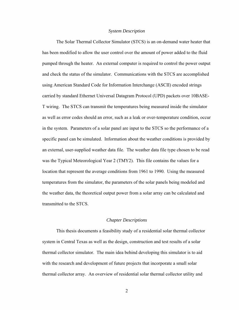
System Description
The Solar Thermal Collector Simulator (STCS) is an on-demand water heater that
has been modified to allow the user control over the amount of power added to the fluid
pumped through the heater. An external computer is required to control the power output
and check the status of the simulator. Communications with the STCS are accomplished
using American Standard Code for Information Interchange (ASCII) encoded strings
carried by standard Ethernet Universal Datagram Protocol (UPD) packets over 10BASE-
T wiring. The STCS can transmit the temperatures being measured inside the simulator
as well as error codes should an error, such as a leak or over-temperature condition, occur
in the system. Parameters of a solar panel are input to the STCS so the performance of a
specific panel can be simulated. Information about the weather conditions is provided by
an external, user-supplied weather data file. The weather data file type chosen to be read
was the Typical Meteorological Year 2 (TMY2). This file contains the values for a
location that represent the average conditions from 1961 to 1990. Using the measured
temperatures from the simulator, the parameters of the solar panels being modeled and
the weather data, the theoretical output power from a solar array can be calculated and
transmitted to the STCS.
Chapter Descriptions
This thesis documents a feasibility study of a residential solar thermal collector
system in Central Texas as well as the design, construction and test results of a solar
thermal collector simulator. The main idea behind developing this simulator is to aid
with the research and development of future projects that incorporate a small solar
thermal collector array. An overview of residential solar thermal collector utility and

3
economic analysis is covered in chapter two. The hardware and software system design
specifics are discussed in chapters three and four. Test results and verification are shown
in chapter five as well as the uncertainty calculations for the system. A user’s manual
that shows how to interface, set up and maintain the STCS system can be found in
Appendix A.

4
CHAPTER TWO
Theory behind the Project
Usefulness of the Project
The need for research in the area of renewable energy has grown greatly in recent
years due to an increase in the price of easily accessible energy sources. This change has
brought about many new opportunities for universities and research centers to build upon
existing technology or develop new strategies for handling how energy systems function.
Both avenues of research could require an experimental test bench to verify and quantify
results. The STCS was created to aid in the development and progress of research in the
field of solar fluid heating. The main purpose of the project is to create a computer
controlled water heater that can replace a small solar thermal collector array in a
hypothetical installation. Using the STCS in a system allows new hardware, as well as
new methods of controlling how the system behaves to be tested more accurately because
the power output from the simulator can be repeated reliably. Repeatability removes any
variability involved with using an actual solar thermal collector, due to the fact that actual
weather conditions cannot be replicated easily.
Solar Feasibility in Central Texas
A solar thermal collector system can be used to augment an existing water heating
installation by preheating the water before it enters the main water heater. When
determining if a solar powered system would be feasible in an area, the two main factors

5
to consider are the amount of solar energy, or insolation, which is available and the
economics associated with installing the system.
The available insolation in an area will determine how much energy can be gained by a
system and thus, how long it will take for the energy offset to pay for the system. The
most common configuration for a non-tracking solar thermal collector system in the
United States has the collector panels facing south and tilted at an angle that is equal to
the latitude of the location plus 15°. The extra 15° helps the collector absorb more
energy during the winter months because the sun is lower in the sky. Figure 2 shows the
yearly average available insolation across the state of Texas for a system that uses the
latitude plus 15° for the slope of the collectors.
Figure 2. Total insolation on a tilted flat plate collector in daym
kWhr2 [2].
Central Texas falls in the region that receives 5.0-5.5 2mkWhr per day on average. This
is equivalent to 208.33-229.17 2mW of irradiance that is available for heating water.
Waco

6
To analyze the economic impact of a solar water heating system, the three main
things that need to be considered are the operating cost of a standard, non-solar power
augmented system, the cost of adding a solar powered system and the operating cost that
would be offset by adding a solar powered system. Appendix E outlines an in depth
conceptual analysis and feasibility study for a sample residential solar thermal collector
system being used in Waco, Texas.
A typical water heating installation only includes a water heating tank which
stores and maintains the temperature of water to be used in the household. Two
important factors affecting the cost of a conventional water heating system are the
efficiency of the heating tank and the price of the energy used to heat the water. There
are other factors that affect operating cost, but their impact would be seen with a solar
powered system as well, thus they do not play a part in the economic analysis. The
efficiency of water heaters depends on the size of the tank and the source of the energy to
provide the heat. Tank size is dependent on needed capacity, or first hour capacity,
which is the peak amount of hot water that would be needed in a one hour period. For a
typical four person family this can vary from 40 to 60 gallons. The larger the tank,
however, the greater the standby heat losses will be. The two main energy sources for
water heaters are electricity and natural gas. Electrical heating is accomplished by
running electrical current through resistive heating elements in direct contact with the
water to be heated. For a natural gas heater there is a burner at the bottom of the water
heater tank that heats the water inside. The average efficiency of electrical water heaters
is between 90% and 95%; while natural gas fueled heaters have an average efficiency that
ranges from 60% to 65% [3].

7
The price of energy used to heat the water plays an important role in determining
if a solar thermal collection system will be feasible at a location. In Waco, Texas the
average price for electricity is $0.1398 per kWh and $46.69 per Mcf for natural gas. To
be able to compare these values a common unit must be used. Throughout the analysis in
this thesis the unit of millions of Btus (MMBtu) will be used, so electricity is $40.96 per
MMBtu, and gas is $45.29 per MMBtu.
After the analysis in Appendix E was completed the payback period was
compared to similar installations in the area. Figure 3 shows the average payback period
times across the state of Texas, with Waco falling in the 10 to 15 year range.
Figure 3. Payback period in terms of years [4].
Based on the analysis performed in Appendix E and information on similar solar
thermal collection systems in the surrounding area the practicality of a system that
augments an existing domestic water heater can be seen. The relatively high initial cost

8
and unfamiliarity with solar thermal collection systems are the two biggest factors that
keep most home owners from considering using this readily available resource to
augment or replace such a large percentage of their overall energy usage.
9
CHAPTER THREE
Hardware Overview
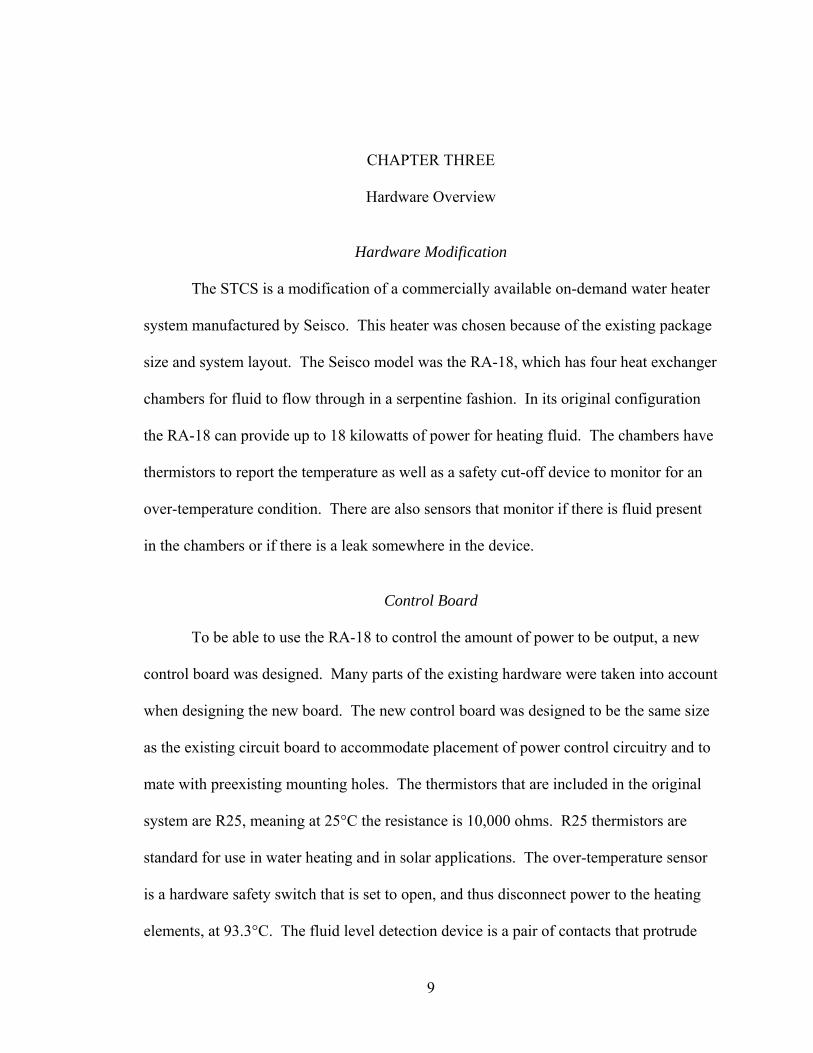
Hardware Modification
The STCS is a modification of a commercially available on-demand water heater
system manufactured by Seisco. This heater was chosen because of the existing package
size and system layout. The Seisco model was the RA-18, which has four heat exchanger
chambers for fluid to flow through in a serpentine fashion. In its original configuration
the RA-18 can provide up to 18 kilowatts of power for heating fluid. The chambers have
thermistors to report the temperature as well as a safety cut-off device to monitor for an
over-temperature condition. There are also sensors that monitor if there is fluid present
in the chambers or if there is a leak somewhere in the device.
Control Board
To be able to use the RA-18 to control the amount of power to be output, a new
control board was designed. Many parts of the existing hardware were taken into account
when designing the new board. The new control board was designed to be the same size
as the existing circuit board to accommodate placement of power control circuitry and to
mate with preexisting mounting holes. The thermistors that are included in the original
system are R25, meaning at 25°C the resistance is 10,000 ohms. R25 thermistors are
standard for use in water heating and in solar applications. The over-temperature sensor
is a hardware safety switch that is set to open, and thus disconnect power to the heating
elements, at 93.3°C. The fluid level detection device is a pair of contacts that protrude
10
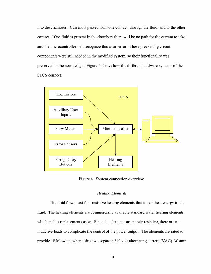
into the chambers. Current is passed from one contact, through the fluid, and to the other
contact. If no fluid is present in the chambers there will be no path for the current to take
and the microcontroller will recognize this as an error. These preexisting circuit
components were still needed in the modified system, so their functionality was
preserved in the new design. Figure 4 shows how the different hardware systems of the
STCS connect.
Figure 4. System connection overview.
Heating Elements
The fluid flows past four resistive heating elements that impart heat energy to the
fluid. The heating elements are commercially available standard water heating elements
which makes replacement easier. Since the elements are purely resistive, there are no
inductive loads to complicate the control of the power output. The elements are rated to
provide 18 kilowatts when using two separate 240 volt alternating current (VAC), 30 amp
Thermistors
Flow Meters
Error Sensors
Microcontroller
Firing Delay Buttons
Auxiliary User Inputs
STCS
Heating Elements
11
circuits, however, in the experiments in this thesis the total power the heating elements
can provide was reduced to 13.5 kilowatts due to two 208 VAC, 30 amp circuits being
used.
Thermistors
Thermistors are semiconductor components whose resistance changes with
respect to temperature. Since the thermistor values are reported by a microcontroller’s
analog-to-digital conversion (ADC) unit, any change in resistance has to be converted to
a change in voltage that ranges between 0V and 5V direct current (DC). To achieve this
conversion an operational amplifier configuration is used to provide a constant current
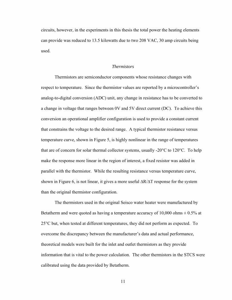
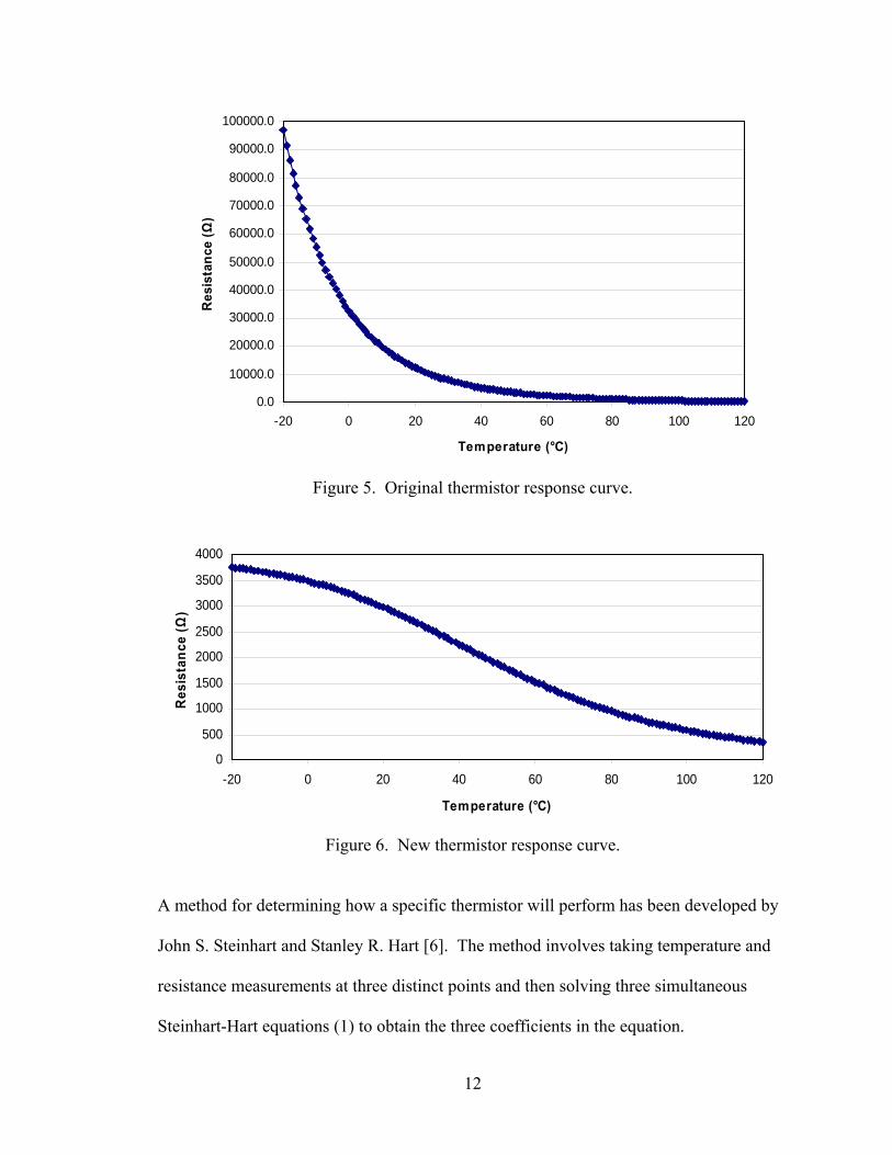
that constrains the voltage to the desired range. A typical thermistor resistance versus
temperature curve, shown in Figure 5, is highly nonlinear in the range of temperatures
that are of concern for solar thermal collector systems, usually -20°C to 120°C. To help
make the response more linear in the region of interest, a fixed resistor was added in
parallel with the thermistor. While the resulting resistance versus temperature curve,
shown in Figure 6, is not linear, it gives a more useful ∆R/∆T response for the system
than the original thermistor configuration.
The thermistors used in the original Seisco water heater were manufactured by
Betatherm and were quoted as having a temperature accuracy of 10,000 ohms ± 0.5% at
25°C but, when tested at different temperatures, they did not perform as expected. To
overcome the discrepancy between the manufacturer’s data and actual performance,
theoretical models were built for the inlet and outlet thermistors as they provide
information that is vital to the power calculation. The other thermistors in the STCS were
calibrated using the data provided by Betatherm.
12
0.0
10000.0
20000.0
30000.0
40000.0
50000.0
60000.0
70000.0
80000.0
90000.0
100000.0
-20 0 20 40 60 80 100 120
Temperature (°C)
Res
ista
nce
(Ω)
Figure 5. Original thermistor response curve.
0
500
1000
1500
2000
2500
3000
3500
4000
-20 0 20 40 60 80 100 120
Temperature (°C)
Res
ista
nce
(Ω)
Figure 6. New thermistor response curve.
A method for determining how a specific thermistor will perform has been developed by
John S. Steinhart and Stanley R. Hart [6]. The method involves taking temperature and
resistance measurements at three distinct points and then solving three simultaneous
Steinhart-Hart equations (1) to obtain the three coefficients in the equation.
13
( ) ( )[ ]3lnln1 RCRBAT
++= (1)
Once the coefficients A, B, and C have been solved, the equation can be used over the
entire range of the thermistor to find the temperature. To provide the most accurate
model of the temperature sensing hardware, the thermistor and current supply had to be
calibrated. To do this the theoretical resistance values of both thermistors had to be
calculated for every degree. To find the resistance of a thermistor given the temperature
the Steinhart-Hart equation can be rearranged to give (2).
⎟⎟⎠
⎞⎜⎜⎝
⎛+−−= 33
22exp αβαβR where
CT
A 1−
=α and 43
23 αβ +⎟⎠⎞
⎜⎝⎛=
CB (2)
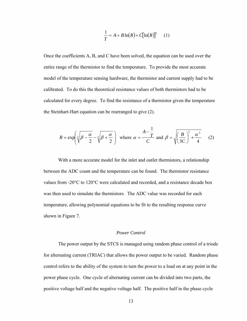
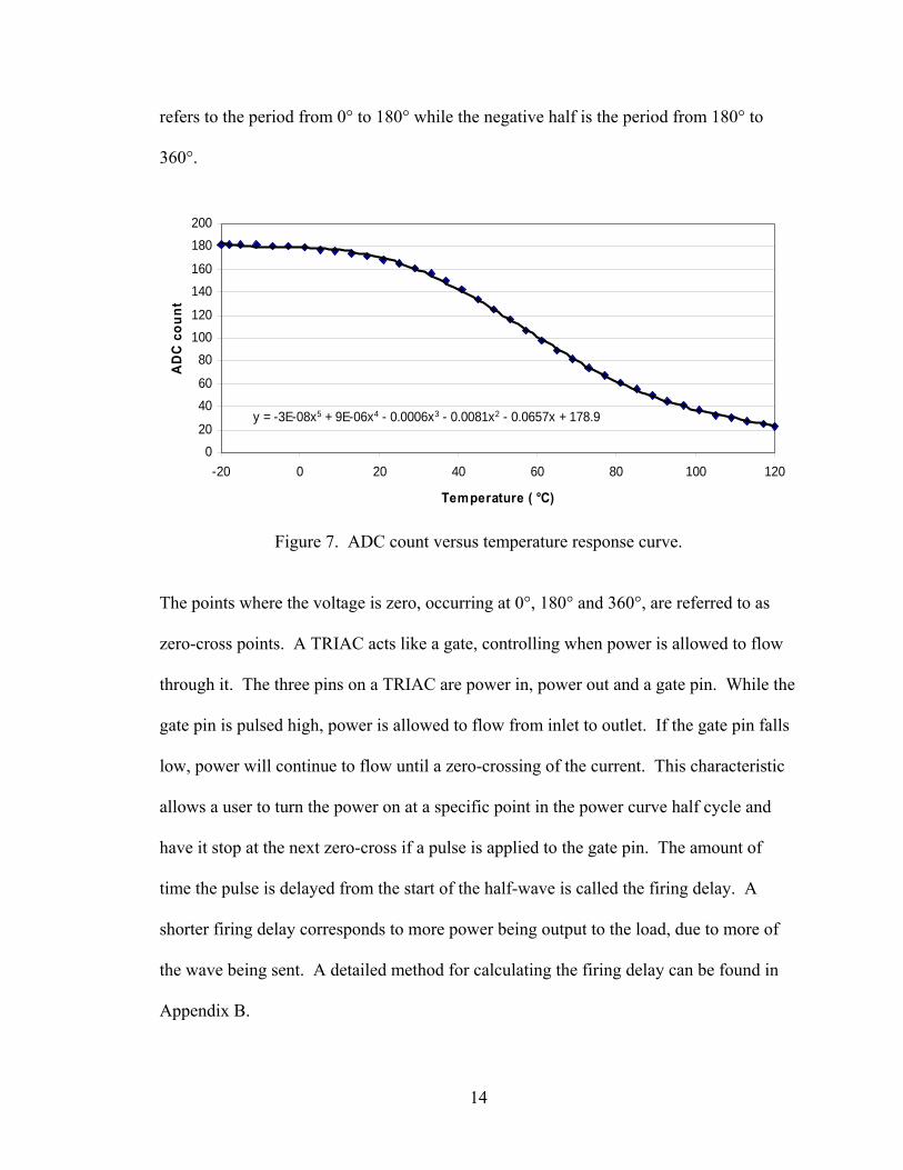
With a more accurate model for the inlet and outlet thermistors, a relationship
between the ADC count and the temperature can be found. The thermistor resistance
values from -20°C to 120°C were calculated and recorded, and a resistance decade box
was then used to simulate the thermistors. The ADC value was recorded for each
temperature, allowing polynomial equations to be fit to the resulting response curve
shown in Figure 7.
Power Control
The power output by the STCS is managed using random phase control of a triode
for alternating current (TRIAC) that allows the power output to be varied. Random phase
control refers to the ability of the system to turn the power to a load on at any point in the
power phase cycle. One cycle of alternating current can be divided into two parts, the
positive voltage half and the negative voltage half. The positive half in the phase cycle
14
refers to the period from 0° to 180° while the negative half is the period from 180° to
360°.
y = -3E-08x5 + 9E-06x4 - 0.0006x3 - 0.0081x2 - 0.0657x + 178.9
020
4060
80100120
140160
180200
-20 0 20 40 60 80 100 120
Temperature ( °C)
AD
C c
ount
Figure 7. ADC count versus temperature response curve.
The points where the voltage is zero, occurring at 0°, 180° and 360°, are referred to as
zero-cross points. A TRIAC acts like a gate, controlling when power is allowed to flow
through it. The three pins on a TRIAC are power in, power out and a gate pin. While the
gate pin is pulsed high, power is allowed to flow from inlet to outlet. If the gate pin falls
low, power will continue to flow until a zero-crossing of the current. This characteristic
allows a user to turn the power on at a specific point in the power curve half cycle and
have it stop at the next zero-cross if a pulse is applied to the gate pin. The amount of
time the pulse is delayed from the start of the half-wave is called the firing delay. A
shorter firing delay corresponds to more power being output to the load, due to more of
the wave being sent. A detailed method for calculating the firing delay can be found in
Appendix B.
15
The firing delay the STCS uses needs to be calibrated periodically. To calibrate
the system there are two push-buttons on the board that allow the firing delay to be
changed by increasing or decreasing a firing delay modifier value. If an output power is
requested that has a known firing delay the user can use an oscilloscope to see the
waveform and adjust the delay modifier amount by pressing and holding one of the two
buttons. Once the proper firing delay has been set the user then presses both buttons to
save the calibration offset into memory. After this calibration the STCS will accurately
output the requested amount of power.
Safety Relays
Before the power is sent to the power control circuitry it passes through two
safety relays that can disconnect the power going to the load. These relays are controlled
by the microcontroller and the over-temperature sensor. If any error is recognized by the
microcontroller, or the temperature gets above 93.3°C, the relays will open,
disconnecting power to the output.
Status LEDs
The STCS has two status light emitting diodes (LED) on the control board to let
the user know if an error has occurred or if the system is functioning normally. The
green LED will remain on if no error is detected and will turn off when an error does
occur. The red LED remains off until an error is detected at which point it turns on. The
status LEDs are also used in the initial set up process of the STCS to let the user know
that the firing delay value has been stored in memory.
16
Flow Meter Inputs
The flow rate of the fluid in the STCS is important to know because it plays a
large part in the calculation of both the requested power and the actual output power.
There are two inputs for flow meters on the STCS. These inputs will accept a signal from
a flow meter that has a pulse output. Pulse output flow meters send a 5V pulse out when
a preset amount of fluid flows through it. When the STCS sees the output from the flow
meter going high, it increments a counter stored in memory. The total count is returned
to the user upon request and then the counter is reset to zero to start counting again.
Knowing what the amount of fluid that causes the flow meter to send a pulse, the number
of pulses that have accumulated and the amount of time over which the number of pulses
has occurred allows a user to calculate the flow rate.
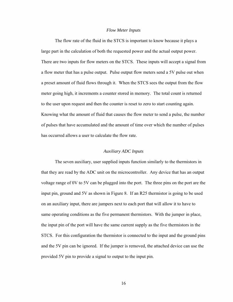
Auxiliary ADC Inputs
The seven auxiliary, user supplied inputs function similarly to the thermistors in
that they are read by the ADC unit on the microcontroller. Any device that has an output
voltage range of 0V to 5V can be plugged into the port. The three pins on the port are the
input pin, ground and 5V as shown in Figure 8. If an R25 thermistor is going to be used
on an auxiliary input, there are jumpers next to each port that will allow it to have to
same operating conditions as the five permanent thermistors. With the jumper in place,
the input pin of the port will have the same current supply as the five thermistors in the
STCS. For this configuration the thermistor is connected to the input and the ground pins
and the 5V pin can be ignored. If the jumper is removed, the attached device can use the
provided 5V pin to provide a signal to output to the input pin.
17
Figure 8. Auxiliary user supplied inputs.
Power Supply
The power that is used to heat the fluid is also used to power the electronics found
in the STCS. A switching power supply is used to step the input voltage down to 12V
which is then used to power the microcontroller, current sources and relays. The power
supply is a commercially available part that connects to the STCS board via wiring
bundles.
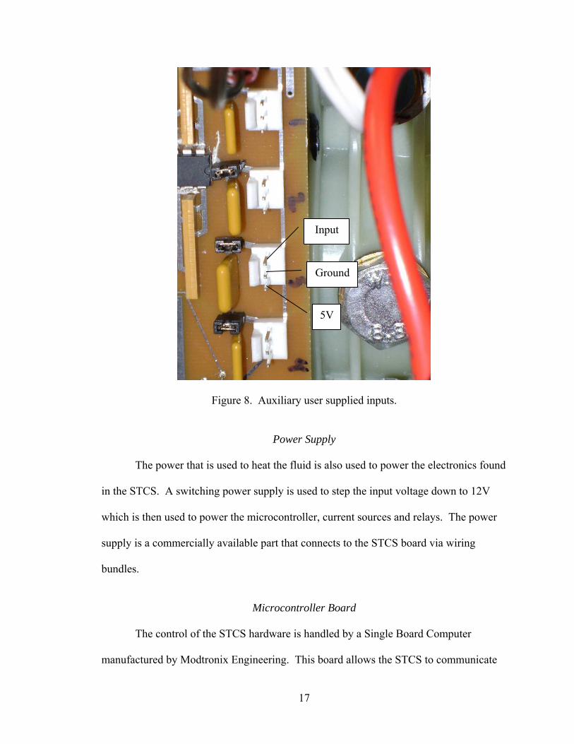
Microcontroller Board
The control of the STCS hardware is handled by a Single Board Computer
manufactured by Modtronix Engineering. This board allows the STCS to communicate
Input
Ground
5V
18
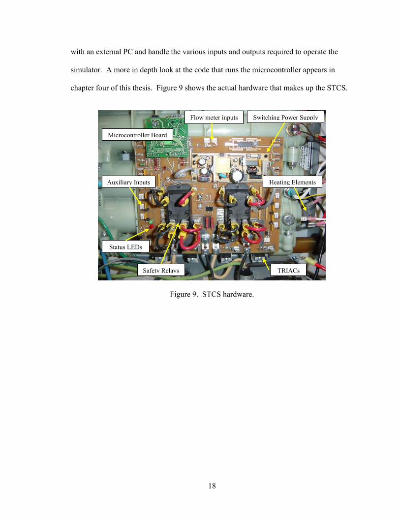
with an external PC and handle the various inputs and outputs required to operate the
simulator. A more in depth look at the code that runs the microcontroller appears in
chapter four of this thesis. Figure 9 shows the actual hardware that makes up the STCS.
Figure 9. STCS hardware.
Microcontroller Board
Flow meter inputs
Auxiliary Inputs
Safety Relays
Switching Power Supply
Heating Elements
Status LEDs
TRIACs

19
CHAPTER FOUR
Software Overview
Microcontroller Board
The operation of the STCS is handled by a microcontroller that interfaces with the
different parts of the system and with an external PC. The external PC can request the
status of the STCS and control the amount of power that the STCS will output. These
communications take place over 10BASE-T wiring using standard Ethernet UPD packets.
The microcontroller must also monitor and control the various parts of the STCS itself.
These operations require digital inputs and outputs, as well as ADC inputs. The control
board must integrate all these features into a single package that can be attached to the
STCS circuit board.
The control board chosen for the STCS is a Singe Board Computer manufactured
by Modtronix Engineering. The SBC65EC, shown in Figure 10, incorporates Ethernet
connectivity, a 64 kilobyte electrically erasable programmable read-only memory
(EEPROM) unit and a microcontroller that has 12, 8-bit ADC inputs and 20 other user
programmable digital inputs or outputs. One benefit of using the SBC65EC is it comes
with a basic code structure that allows the programmer the ability to modify existing
source code instead of having to write new functions. This code includes the necessary
functions to use the Ethernet port and the ADC unit on the SBC65EC. Another benefit of
using the SBC65EC is the 40-pin daughter board connector that allows easier integration
into an outside system.
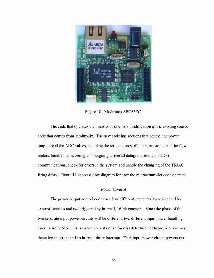
20
Figure 10. Modtronix SBC65EC.
The code that operates the microcontroller is a modification of the existing source
code that comes from Modtronix. The new code has sections that control the power
output, read the ADC values, calculate the temperatures of the thermistors, read the flow
meters, handle the incoming and outgoing universal datagram protocol (UDP)
communications, check for errors in the system and handle the changing of the TRIAC
firing delay. Figure 11 shows a flow diagram for how the microcontroller code operates.
Power Control
The power output control code uses four different interrupts, two triggered by
external sources and two triggered by internal, 16-bit counters. Since the phase of the
two separate input power circuits will be different, two different input power handling
circuits are needed. Each circuit consists of zero-cross detection hardware, a zero-cross
detection interrupt and an internal timer interrupt. Each input power circuit powers two
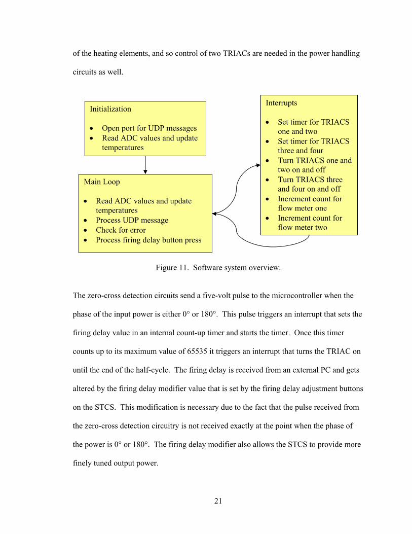
21
of the heating elements, and so control of two TRIACs are needed in the power handling
circuits as well.
Figure 11. Software system overview.
The zero-cross detection circuits send a five-volt pulse to the microcontroller when the
phase of the input power is either 0° or 180°. This pulse triggers an interrupt that sets the
firing delay value in an internal count-up timer and starts the timer. Once this timer
counts up to its maximum value of 65535 it triggers an interrupt that turns the TRIAC on
until the end of the half-cycle. The firing delay is received from an external PC and gets
altered by the firing delay modifier value that is set by the firing delay adjustment buttons
on the STCS. This modification is necessary due to the fact that the pulse received from
the zero-cross detection circuitry is not received exactly at the point when the phase of
the power is 0° or 180°. The firing delay modifier also allows the STCS to provide more
finely tuned output power.
Main Loop • Read ADC values and update
temperatures • Process UDP message • Check for error • Process firing delay button press
Initialization • Open port for UDP messages • Read ADC values and update
temperatures
Interrupts • Set timer for TRIACS
one and two • Set timer for TRIACS
three and four • Turn TRIACS one and
two on and off • Turn TRIACS three
and four on and off • Increment count for
flow meter one • Increment count for
flow meter two
22
ADC Handling
The code provided by Modtronix initializes and handles the ADC unit allowing
the values for each channel to be easily used elsewhere in the code. A circular ten-point
average is kept for all the ADC values by keeping track of the previous nine values and
adding them to the current value. This helps to help minimize noise in the sampling of
the thermistors or other devices that may be connected to the STCS. The outcome of this
is the average of the ADC values multiplied by ten which allows the first decimal place to
be reported.
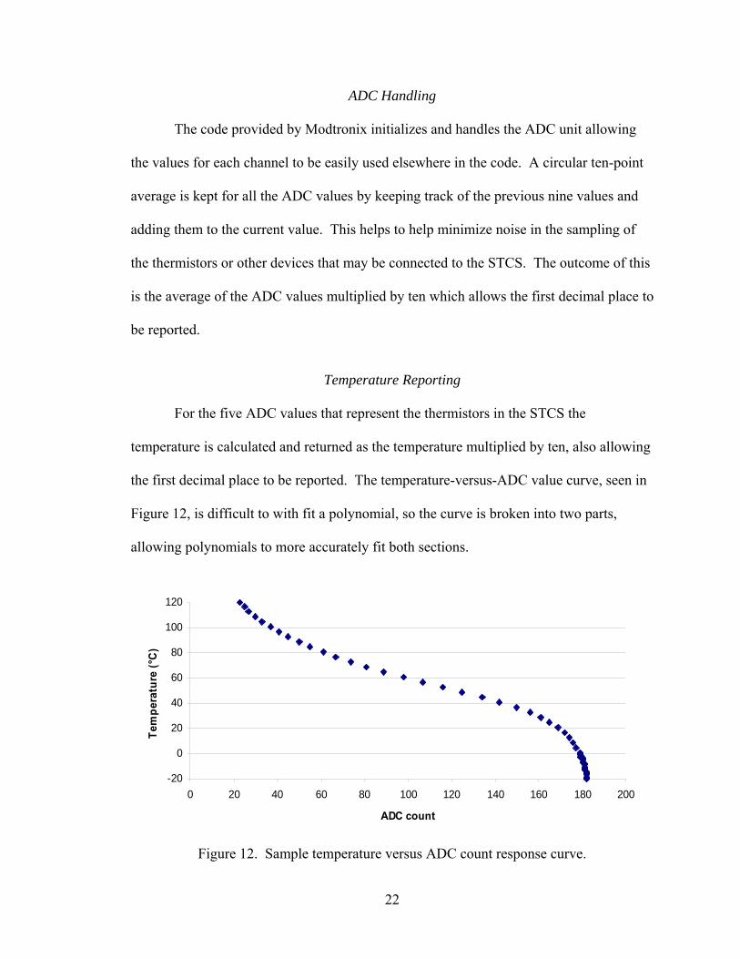
Temperature Reporting
For the five ADC values that represent the thermistors in the STCS the
temperature is calculated and returned as the temperature multiplied by ten, also allowing
the first decimal place to be reported. The temperature-versus-ADC value curve, seen in
Figure 12, is difficult to with fit a polynomial, so the curve is broken into two parts,
allowing polynomials to more accurately fit both sections.
-20
0
20
40
60
80
100
120
0 20 40 60 80 100 120 140 160 180 200
ADC count
Tem
pera
ture
(°C
)
Figure 12. Sample temperature versus ADC count response curve.
23
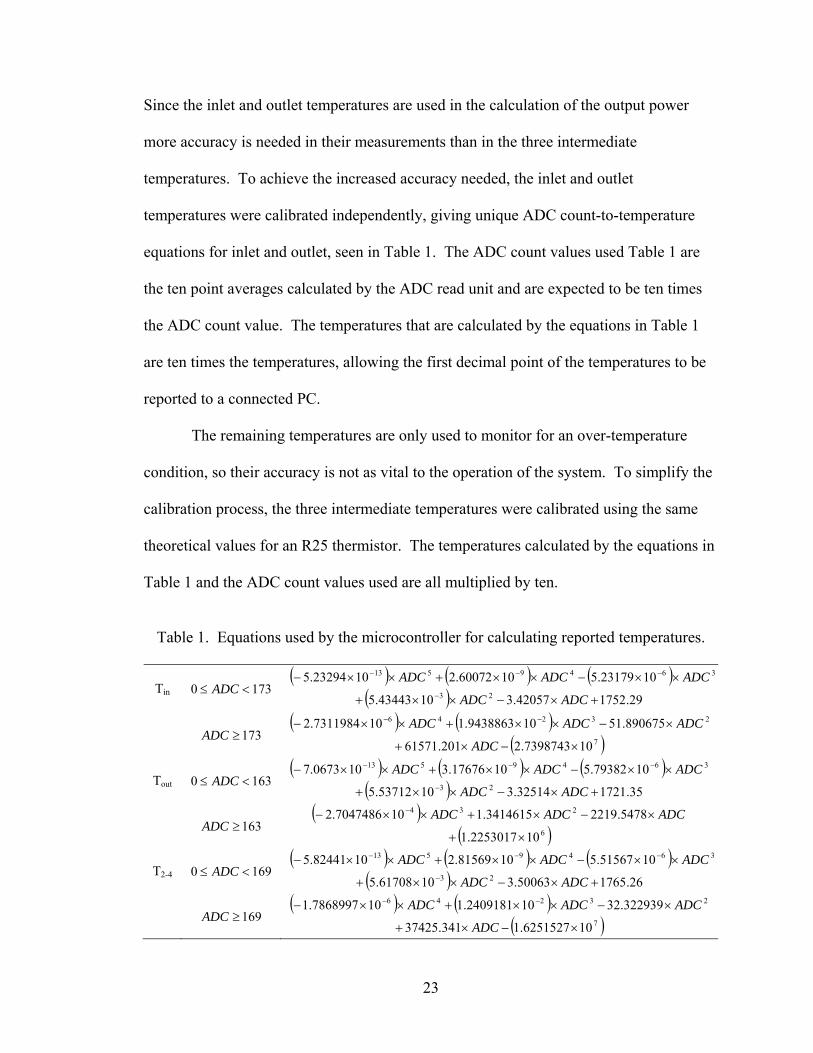
Since the inlet and outlet temperatures are used in the calculation of the output power
more accuracy is needed in their measurements than in the three intermediate
temperatures. To achieve the increased accuracy needed, the inlet and outlet
temperatures were calibrated independently, giving unique ADC count-to-temperature
equations for inlet and outlet, seen in Table 1. The ADC count values used Table 1 are
the ten point averages calculated by the ADC read unit and are expected to be ten times
the ADC count value. The temperatures that are calculated by the equations in Table 1
are ten times the temperatures, allowing the first decimal point of the temperatures to be
reported to a connected PC.
The remaining temperatures are only used to monitor for an over-temperature
condition, so their accuracy is not as vital to the operation of the system. To simplify the
calibration process, the three intermediate temperatures were calibrated using the same
theoretical values for an R25 thermistor. The temperatures calculated by the equations in
Table 1 and the ADC count values used are all multiplied by ten.
Table 1. Equations used by the microcontroller for calculating reported temperatures.
Tin 1730 <≤ ADC ( ) ( ) ( ) 3649513 1023179.51060072.21023294.5 ADCADCADC ××−××+××− −−−
( ) 29.175242057.31043443.5 23 +×−××+ − ADCADC
173≥ADC ( ) ( ) 23246 890675.51109438863.1107311984.2 ADCADCADC ×−××+××− −−
( )7107398743.2201.61571 ×−×+ ADC
Tout 1630 <≤ ADC ( ) ( ) ( ) 3649513 1079382.51017676.3100673.7 ADCADCADC ××−××+××− −−−
( ) 35.172132514.31053712.5 23 +×−××+ − ADCADC
163≥ADC ( ) ADCADCADC ×−×+××− − 5478.22193414615.1107047486.2 234
( )6102253017.1 ×+
T2-4 1690 <≤ ADC ( ) ( ) ( ) 3649513 1051567.51081569.21082441.5 ADCADCADC ××−××+××− −−−
( ) 26.176550063.31061708.5 23 +×−××+ − ADCADC
169≥ADC ( ) ( ) 23246 322939.32102409181.1107868997.1 ADCADCADC ×−××+××− −−
( )7106251527.1341.37425 ×−×+ ADC
24
The equations in Table 1 are the ones used in the code for the microcontroller, thus are
provided for reference. The end result the attached PC would see from these equations
would be a value for the temperature times ten.
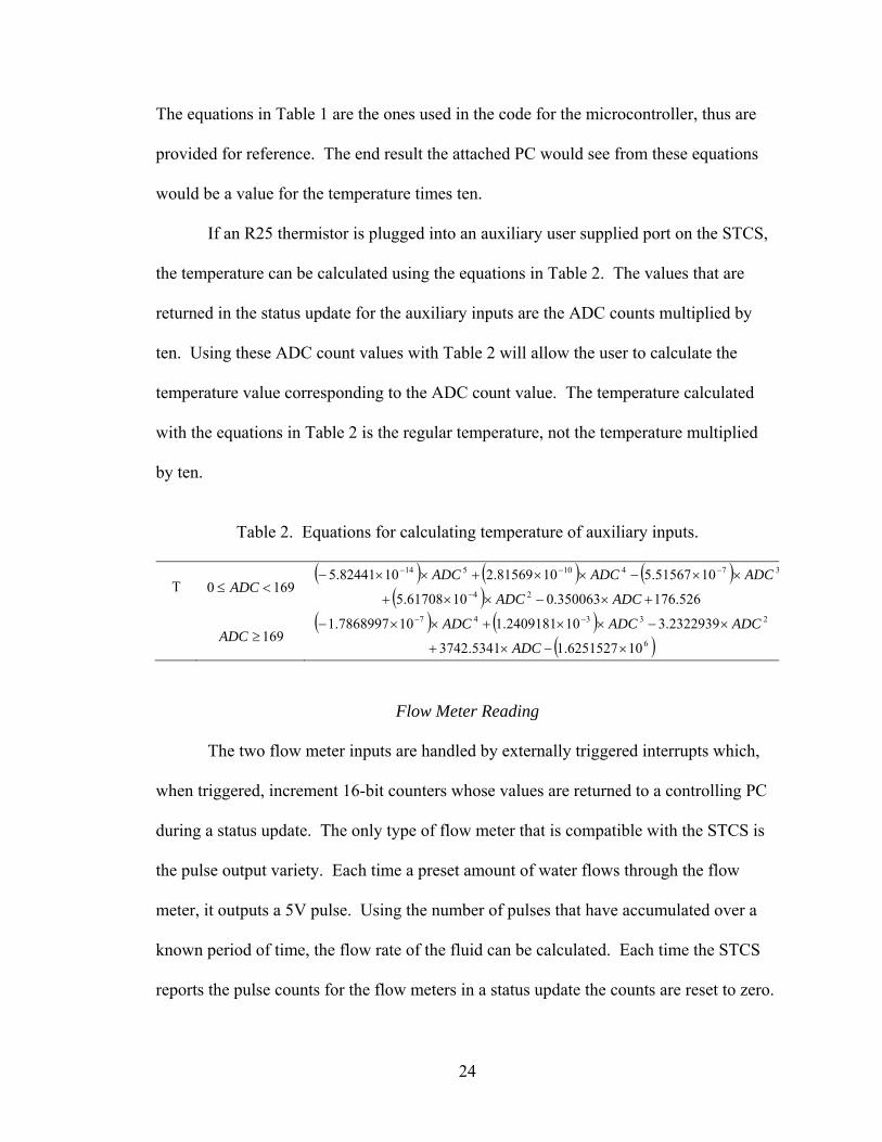
If an R25 thermistor is plugged into an auxiliary user supplied port on the STCS,
the temperature can be calculated using the equations in Table 2. The values that are
returned in the status update for the auxiliary inputs are the ADC counts multiplied by
ten. Using these ADC count values with Table 2 will allow the user to calculate the
temperature value corresponding to the ADC count value. The temperature calculated
with the equations in Table 2 is the regular temperature, not the temperature multiplied
by ten.
Table 2. Equations for calculating temperature of auxiliary inputs.
T 1690 <≤ ADC ( ) ( ) ( ) 37410514 1051567.51081569.21082441.5 ADCADCADC ××−××+××− −−−
( ) 526.176350063.01061708.5 24 +×−××+ − ADCADC
169≥ADC ( ) ( ) 23347 2322939.3102409181.1107868997.1 ADCADCADC ×−××+××− −−
( )6106251527.15341.3742 ×−×+ ADC
Flow Meter Reading
The two flow meter inputs are handled by externally triggered interrupts which,
when triggered, increment 16-bit counters whose values are returned to a controlling PC
during a status update. The only type of flow meter that is compatible with the STCS is
the pulse output variety. Each time a preset amount of water flows through the flow
meter, it outputs a 5V pulse. Using the number of pulses that have accumulated over a
known period of time, the flow rate of the fluid can be calculated. Each time the STCS
reports the pulse counts for the flow meters in a status update the counts are reset to zero.

25
The flow meter used in the testing of the system would output a pulse for every 0.05
gallons that flowed through it.
UDP Communications
The UDP communications use preexisting functions that are available in the
Modtronix source code to set up the UDP receive and send ports, put received packets
into a buffer and send packets from a buffer. The microcontroller continuously checks
the UDP receive buffer for an ASCII string and then verifies if the received string is a
valid output power command or a request for status update. If the string is a power
command it reads the delay value and which elements to turn on and stores the data so it
can be accessed by other functions in the code. If a request for status update is received
the microcontroller builds the ASCII string that contains the information about the
system, places it in a transmit buffer, and sends the contents of the buffer to the PC that
requested the status. If no error is occurring at the time of the request, the output string
will contain the temperatures of the five thermistors multiplied by ten, the ADC count of
the seven user-supplied auxiliary inputs multiplied by ten, and the counts of the two flow
meters. If there is an error present in the system at the time of the request, the output
string will contain information about the error that is occurring. For an over-temperature
condition the string contains which thermistor is over the limit of 93.3°C. If a leak is
detected or if there is no fluid present in the chambers the ASCII string will contain the
corresponding error message. If the received string does not contain a valid power
command or status update request, the string is discarded and no change or response is
made.
26
Error Handling
The microcontroller code that handles errors in the STCS checks if any
thermistors are reading a temperature that is above 93.3°C, if there is a leak detected or if
there is fluid in the chambers. When no errors are detected, the internal error flag in the
microcontroller code is set to zero which allows the TRIACs to turn on. If one of the
thermistors is reporting a temperature that is greater than 93.3°C, the error flag is set to a
value between one and five, corresponding to which thermistor reported the temperature.
When fluid is not present in the chambers, the flag will be set to six and if a leak is
detected the flag will be set to seven. In the even of any error occurring, the power relays
are opened, the green status LED is turned off and the red status LED is turned on. If a
request for a status update is received at any point when the error flag is set to any non-
zero value, the STCS will respond with the corresponding error code. The power control
code also checks if the error flag is zero before allowing the TRIACs to be turned on.
Once an error has been cleared in the system the error handling code will set the error
flag to zero, close the power relays, turn on the green status LED and turn off the red
status LED.
TRIAC Firing Delay
The code responsible for changing the TRIAC firing delay monitors the firing
delay adjustment buttons for a change then takes the appropriate action. If only one
button is pressed for two seconds the firing delay is increased or decreased depending on
which button is depressed. If both buttons are pressed simultaneously for two seconds,
the microcontroller checks if the current firing delay value is the same as what is saved in
the EEPROM and, if they are different, writes the new delay value in the EEPROM so it
27
can be accessed by the microcontroller after the power to the STCS has been reset. When
the new value is saved, the two status LEDs will blink, letting the user know the process
is complete.
External Control Program
National Instruments’ LabVIEW was used to control the STCS during the
development and verification stages of this thesis. LabVIEW was chosen because it
allows a user to program equations, set up real time control loops and control external
devices within a single programming window to calculate the output power and
communicate with the STCS while adhering to a strict timing schedule. The equations
LabVIEW uses to calculate the output power can be found in Appendix D.

28
CHAPTER FIVE
Test Results and Verification
System Performance Goals
In order to verify that the STCS performs as intended, several tests have to be run
and the results compared against a reliable data source. The two goals of the STCS are to
accurately and repeatedly simulate the output of a small array of solar thermal collectors.
For both the accuracy and the repeatability of the system to be verified there has to be an
accurate and reliable source of data for comparison. The Transient Energy System
Simulation Tool (TRNSYS) was used to provide the data for comparison to the
performance of the STCS. To test for accuracy the uncertainty of the power output was
calculated and the output would need to fall within the error bounds. To show the system
is repeatable five trials were run with the same input parameters over the same two hour
period of a theoretical day. The power output from the five trials being close to each
other would confirm the STCS’s repeatability.
The Solar Rating and Certification Corporation (SRCC) tests and rates the
majority of all solar thermal collectors available. Panels are tested for durability, quality
of construction, thermal expansion or contraction resistance and energy output. Since the
ratings have to be updated yearly for every panel, computer simulations are employed to
test the energy output portion of the validation process. The software chosen to model
these panels is TRNSYS due to its high accuracy in modeling energy systems. Selections
of panels are physically tested along with software simulations to verify the panel rating
29
results from TRNSYS. Based on the accuracy associated with using TRNSYS to
simulate the energy output of a panel it was decided that the results from the STCS could
be compared to the simulated results from TRNSYS.
The calculations for the uncertainty of the power output by the STCS are shown
in Appendix F, along with the actual values for the STCS. The total output power
uncertainty is given by (3).
( )( ) ( ) ( )222 936.59788016.42566384.73 mmTTU ioQout && +−+−= (3)
oT is the outlet temperature in °C, iT is the inlet temperature in °C and m& is the flow rate
of the fluid through the STCS in kg/s. Since each of these are variable, the output power
uncertainty changes based on all three inputs.
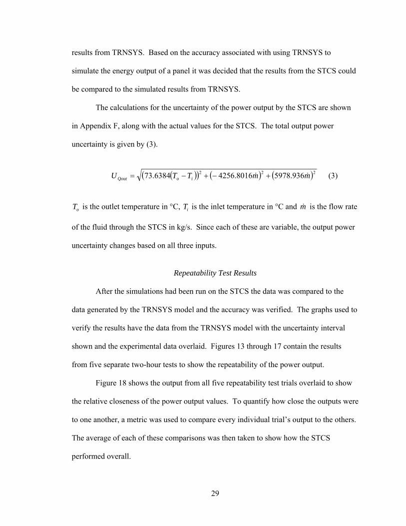
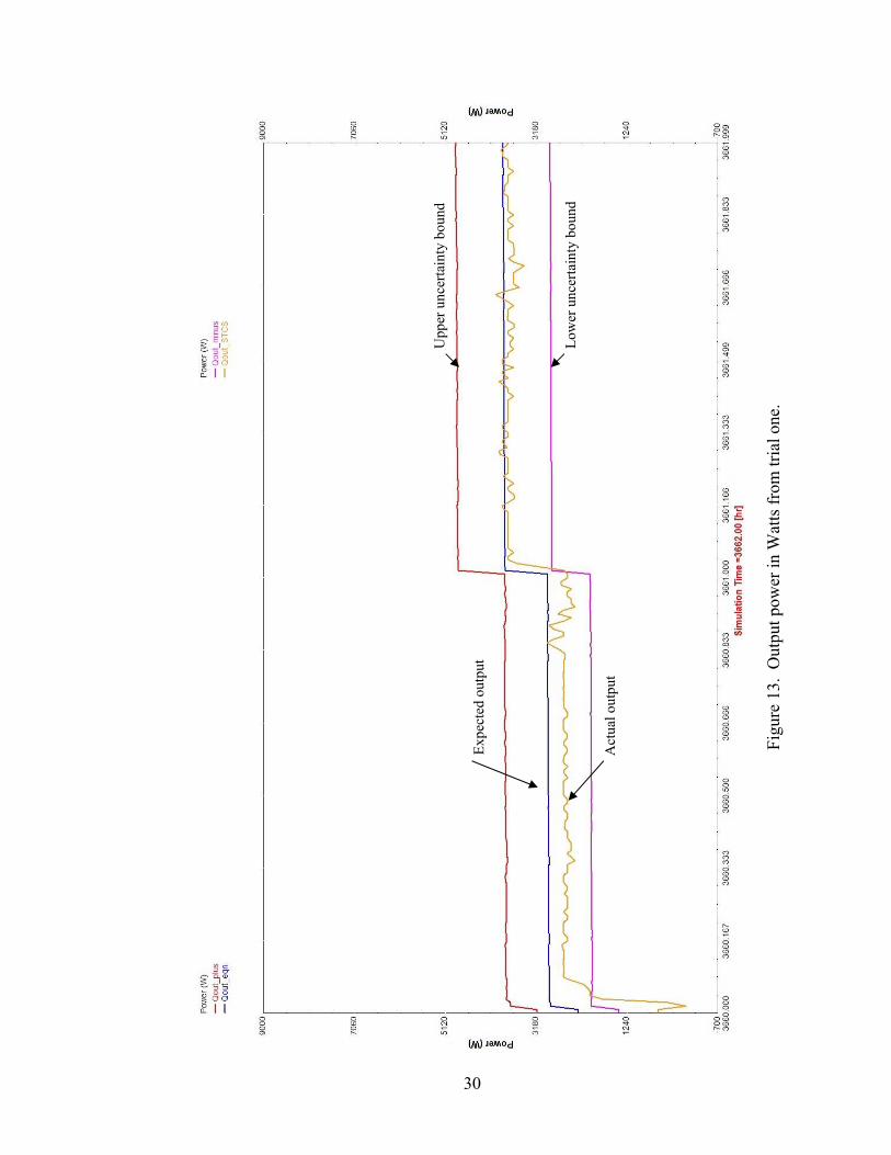
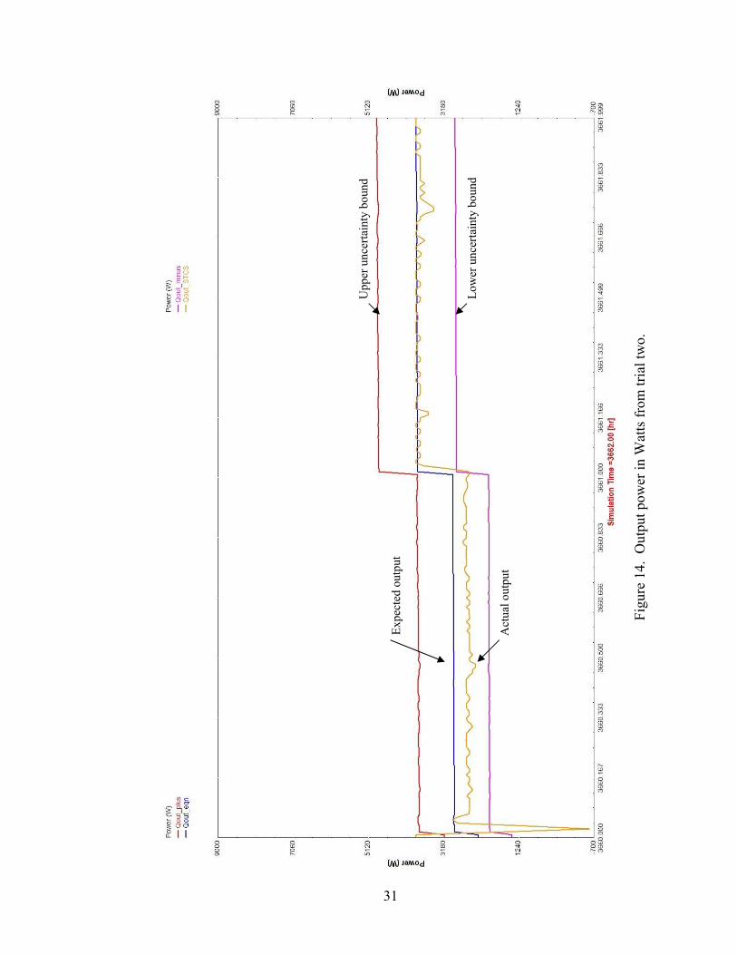
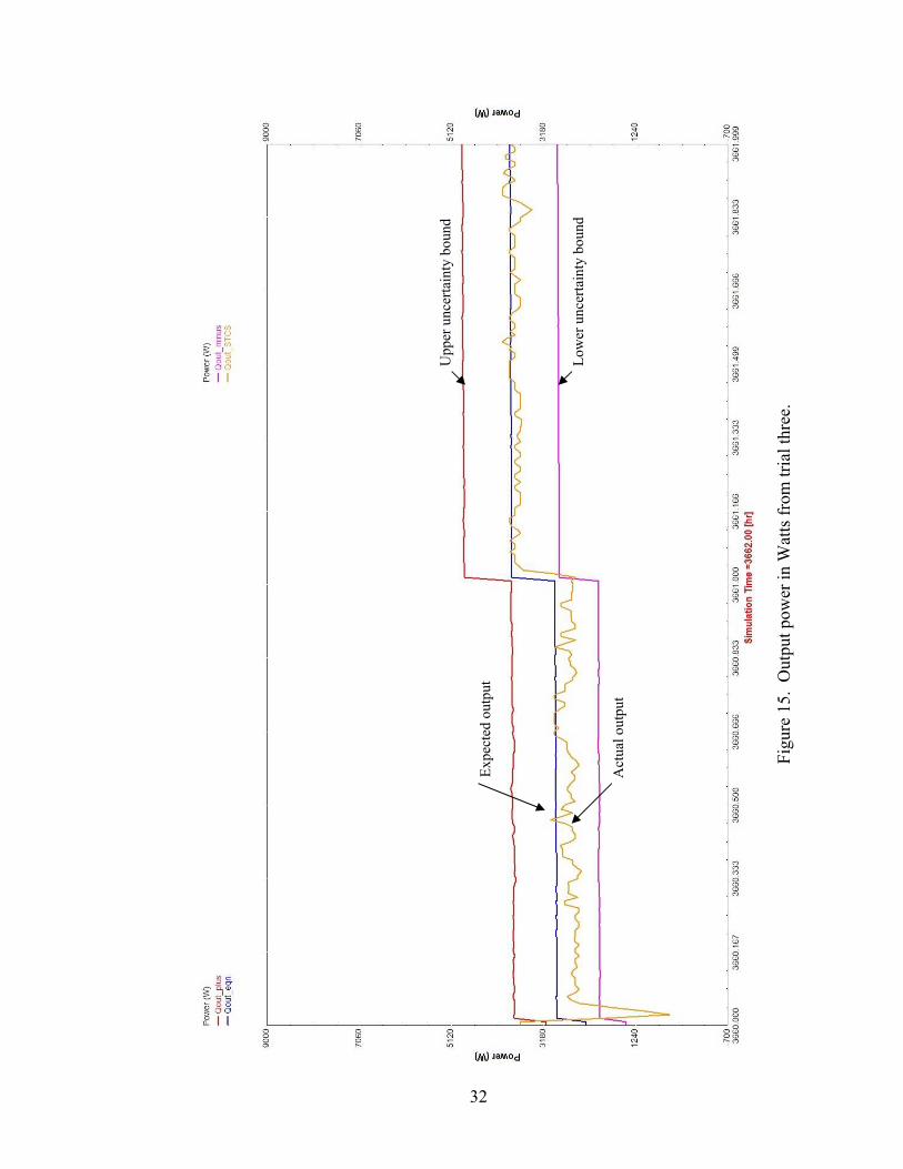
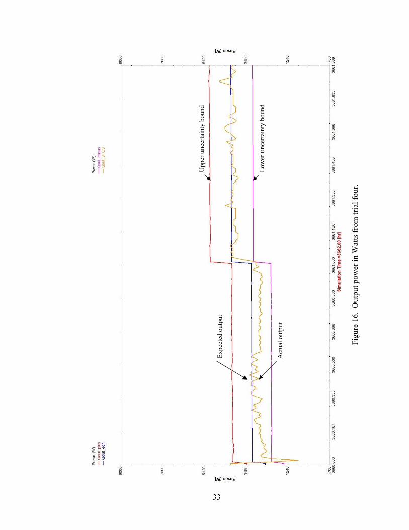
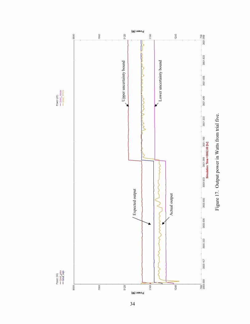
Repeatability Test Results
After the simulations had been run on the STCS the data was compared to the
data generated by the TRNSYS model and the accuracy was verified. The graphs used to
verify the results have the data from the TRNSYS model with the uncertainty interval
shown and the experimental data overlaid. Figures 13 through 17 contain the results
from five separate two-hour tests to show the repeatability of the power output.
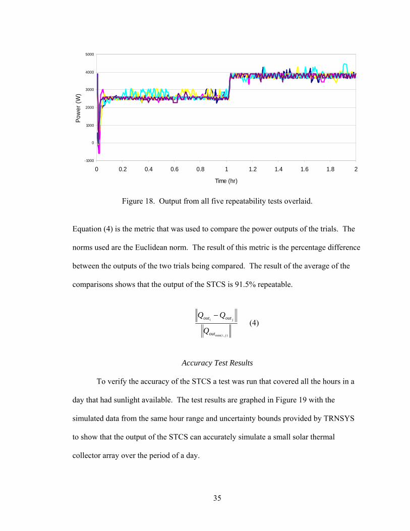
Figure 18 shows the output from all five repeatability test trials overlaid to show
the relative closeness of the power output values. To quantify how close the outputs were
to one another, a metric was used to compare every individual trial’s output to the others.
The average of each of these comparisons was then taken to show how the STCS
performed overall.
30
Upp
er u
ncer
tain
ty b
ound
Low
er u
ncer
tain
ty b
ound
Expe
cted
out
put
Act
ual o
utpu
t
Figu
re 1
3. O
utpu
t pow
er in
Wat
ts fr
om tr
ial o
ne.
31
Upp
er u
ncer
tain
ty b
ound
Low
er u
ncer
tain
ty b
ound
Expe
cted
out
put
Act
ual o
utpu
t
Figu
re 1
4. O
utpu
t pow
er in
Wat
ts fr
om tr
ial t
wo.
32
Upp
er u
ncer
tain
ty b
ound
Low
er u
ncer
tain
ty b
ound
Expe
cted
out
put
Act
ual o
utpu
t
Figu
re 1
5. O
utpu
t pow
er in
Wat
ts fr
om tr
ial t
hree
.
33
Upp
er u
ncer
tain
ty b
ound
Low
er u
ncer
tain
ty b
ound
Expe
cted
out
put
Act
ual o
utpu
t
Figu
re 1
6. O
utpu
t pow
er in
Wat
ts fr
om tr
ial f
our.
34
Upp
er u
ncer
tain
ty b
ound
Low
er u
ncer
tain
ty b
ound
Expe
cted
out
put
Act
ual o
utpu
t
Figu
re 1
7. O
utpu
t pow
er in
Wat
ts fr
om tr
ial f
ive.
35
-1000
0
1000
2000
3000
4000
5000
0 0.2 0.4 0.6 0.8 1 1.2 1.4 1.6 1.8 2
Time (hr)
Pow
er (W
)
Figure 18. Output from all five repeatability tests overlaid.
Equation (4) is the metric that was used to compare the power outputs of the trials. The
norms used are the Euclidean norm. The result of this metric is the percentage difference
between the outputs of the two trials being compared. The result of the average of the
comparisons shows that the output of the STCS is 91.5% repeatable.
),min( ji
ji
out
outout
Q
QQ − (4)
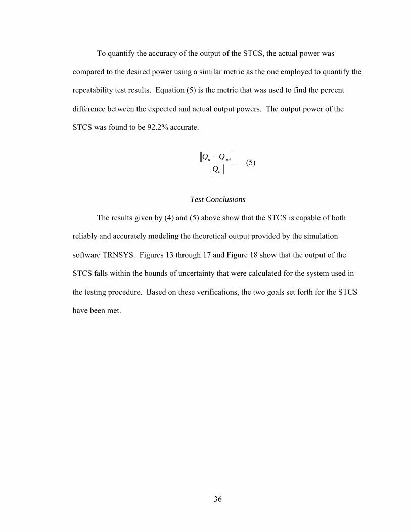
Accuracy Test Results
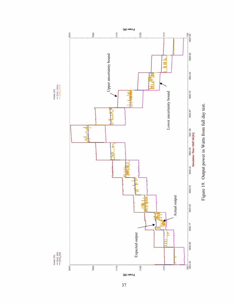
To verify the accuracy of the STCS a test was run that covered all the hours in a
day that had sunlight available. The test results are graphed in Figure 19 with the
simulated data from the same hour range and uncertainty bounds provided by TRNSYS
to show that the output of the STCS can accurately simulate a small solar thermal
collector array over the period of a day.
36
To quantify the accuracy of the output of the STCS, the actual power was
compared to the desired power using a similar metric as the one employed to quantify the
repeatability test results. Equation (5) is the metric that was used to find the percent
difference between the expected and actual output powers. The output power of the
STCS was found to be 92.2% accurate.
u
outu
QQQ −
(5)
Test Conclusions
The results given by (4) and (5) above show that the STCS is capable of both
reliably and accurately modeling the theoretical output provided by the simulation
software TRNSYS. Figures 13 through 17 and Figure 18 show that the output of the
STCS falls within the bounds of uncertainty that were calculated for the system used in
the testing procedure. Based on these verifications, the two goals set forth for the STCS
have been met.
37
Upp
er u
ncer
tain
ty b
ound
Low
er u
ncer
tain
ty b
ound
Expe
cted
out
put
Act
ual o
utpu
t
Figu
re 1
9. O
utpu
t pow
er in
Wat
ts fr
om fu
ll da
y te
st.

38
APPENDICES
39
APPENDIX A
User’s Manual
This document will outline how to properly interface with, set up and maintain the
STCS. Interfacing with the STCS requires a computer with a program that is capable of
sending and receiving standard Ethernet UPD packets over 10BASE-T wiring. Once the
STCS has been installed and the plumbing and electrical supplies have been connected
there is a one-time set up that has to be performed for the system to operate accurately.
The maintenance procedure will keep the system running accurately and error free.
Interfacing with the STCS
The program that the will be used to send and receive UDP packets to and from
the STCS needs to have the ability to interpret what is sent and received as ASCII strings.
The two ASCII strings that can be transmitted, that the STCS recognizes, are a request
for a status update and a value that corresponds to output power, as shown in Table A.1.
When the STCS receives a request for a status update, and no error is present, it will
respond with an ASCII string that contains the temperature of the five thermistors, the
ADC count for the seven auxiliary user supplied inputs and the count for the two flow
meters. If an error is present and the STCS receives a request for a status update it will
respond with an ASCII string that corresponds to which error has occurred. The three
types of errors that the STCS can detect are a thermistor that is sensing a temperature that
is greater than 93.3°C, if there is no fluid in the chambers, and if the is a leak inside the
system.
40
Table A.1. ASCII strings transmitted to the STCS.
Request for Status Update Packet Format (1 byte): RR ASCII formatted ‘R’ for Request for status update.
Heater Power Level Packet Format (11 bytes): PmmmmmEnnnn
P ASCII formatted ‘P’ for Power level. mmmmm ASCII formatted five-digit number between ‘00000’ and ‘37266’
corresponding to desired output power. Characters other than numbers will turn off all output power. ‘P’ > 37266 turns off all output power.
E ASCII formatted ‘E’ for Element. nnnn ASCII formatted four-digit number of zeros and ones. For example,
‘0100’ indicates that element 2 should operate at the specified power level but elements 1, 3 and 4 should remain off. Characters other than ‘1’ will be interpreted as a ‘0’.
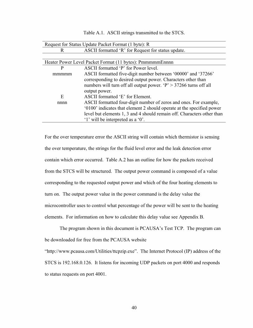
For the over temperature error the ASCII string will contain which thermistor is sensing
the over temperature, the strings for the fluid level error and the leak detection error
contain which error occurred. Table A.2 has an outline for how the packets received
from the STCS will be structured. The output power command is composed of a value
corresponding to the requested output power and which of the four heating elements to
turn on. The output power value in the power command is the delay value the
microcontroller uses to control what percentage of the power will be sent to the heating
elements. For information on how to calculate this delay value see Appendix B.
The program shown in this document is PCAUSA’s Test TCP. The program can
be downloaded for free from the PCAUSA website
“http://www.pcausa.com/Utilities/ttcpzip.exe”. The Internet Protocol (IP) address of the
STCS is 192.168.0.126. It listens for incoming UDP packets on port 4000 and responds
to status requests on port 4001.
41
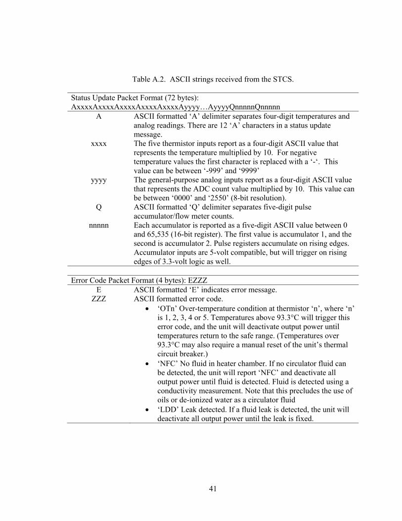
Table A.2. ASCII strings received from the STCS.
Status Update Packet Format (72 bytes): AxxxxAxxxxAxxxxAxxxxAxxxxAyyyy…AyyyyQnnnnnQnnnnn
A ASCII formatted ‘A’ delimiter separates four-digit temperatures and analog readings. There are 12 ‘A’ characters in a status update message.
xxxx The five thermistor inputs report as a four-digit ASCII value that represents the temperature multiplied by 10. For negative temperature values the first character is replaced with a ‘-‘. This value can be between ‘-999’ and ‘9999’
yyyy The general-purpose analog inputs report as a four-digit ASCII value that represents the ADC count value multiplied by 10. This value can be between ‘0000’ and ‘2550’ (8-bit resolution).
Q ASCII formatted ‘Q’ delimiter separates five-digit pulse accumulator/flow meter counts.
nnnnn Each accumulator is reported as a five-digit ASCII value between 0 and 65,535 (16-bit register). The first value is accumulator 1, and the second is accumulator 2. Pulse registers accumulate on rising edges. Accumulator inputs are 5-volt compatible, but will trigger on rising edges of 3.3-volt logic as well.
Error Code Packet Format (4 bytes): EZZZ
E ASCII formatted ‘E’ indicates error message. ZZZ ASCII formatted error code.
• ‘OTn’ Over-temperature condition at thermistor ‘n’, where ‘n’ is 1, 2, 3, 4 or 5. Temperatures above 93.3°C will trigger this error code, and the unit will deactivate output power until temperatures return to the safe range. (Temperatures over 93.3°C may also require a manual reset of the unit’s thermal circuit breaker.)
• ‘NFC’ No fluid in heater chamber. If no circulator fluid can be detected, the unit will report ‘NFC’ and deactivate all output power until fluid is detected. Fluid is detected using a conductivity measurement. Note that this precludes the use of oils or de-ionized water as a circulator fluid
• ‘LDD’ Leak detected. If a fluid leak is detected, the unit will deactivate all output power until the leak is fixed.
42
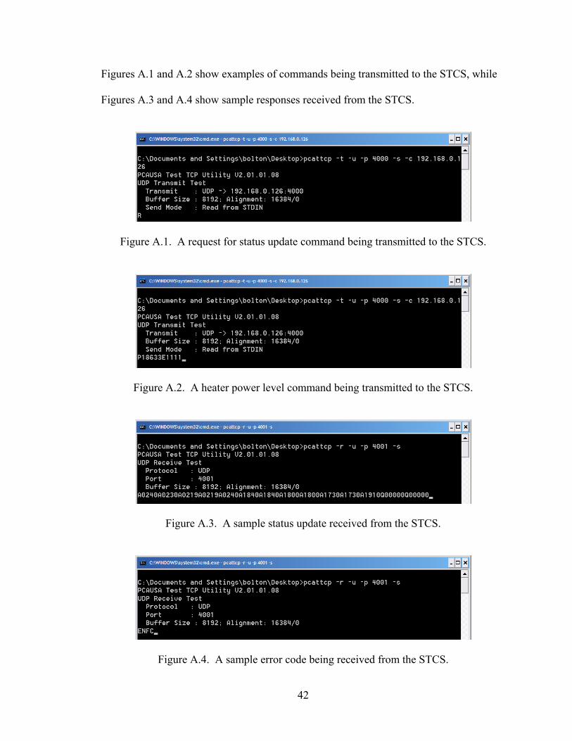
Figures A.1 and A.2 show examples of commands being transmitted to the STCS, while
Figures A.3 and A.4 show sample responses received from the STCS.
Figure A.1. A request for status update command being transmitted to the STCS.
Figure A.2. A heater power level command being transmitted to the STCS.
Figure A.3. A sample status update received from the STCS.
Figure A.4. A sample error code being received from the STCS.
43
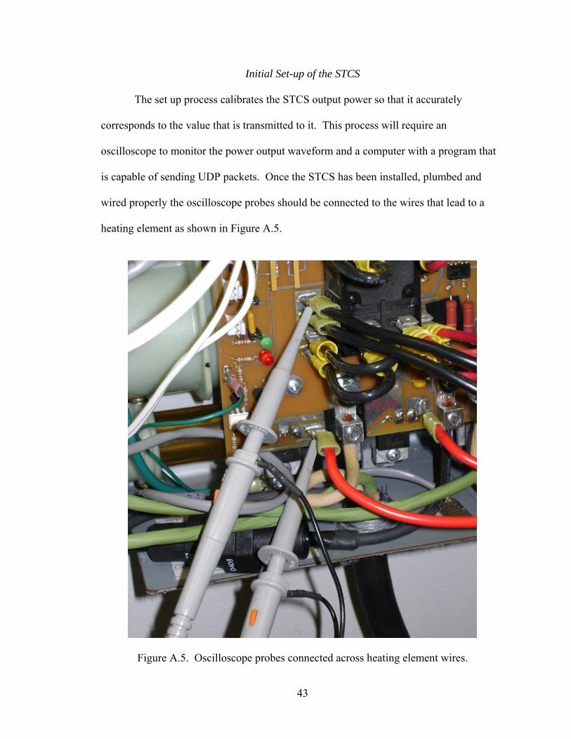
Initial Set-up of the STCS
The set up process calibrates the STCS output power so that it accurately
corresponds to the value that is transmitted to it. This process will require an
oscilloscope to monitor the power output waveform and a computer with a program that
is capable of sending UDP packets. Once the STCS has been installed, plumbed and
wired properly the oscilloscope probes should be connected to the wires that lead to a
heating element as shown in Figure A.5.
Figure A.5. Oscilloscope probes connected across heating element wires.
44
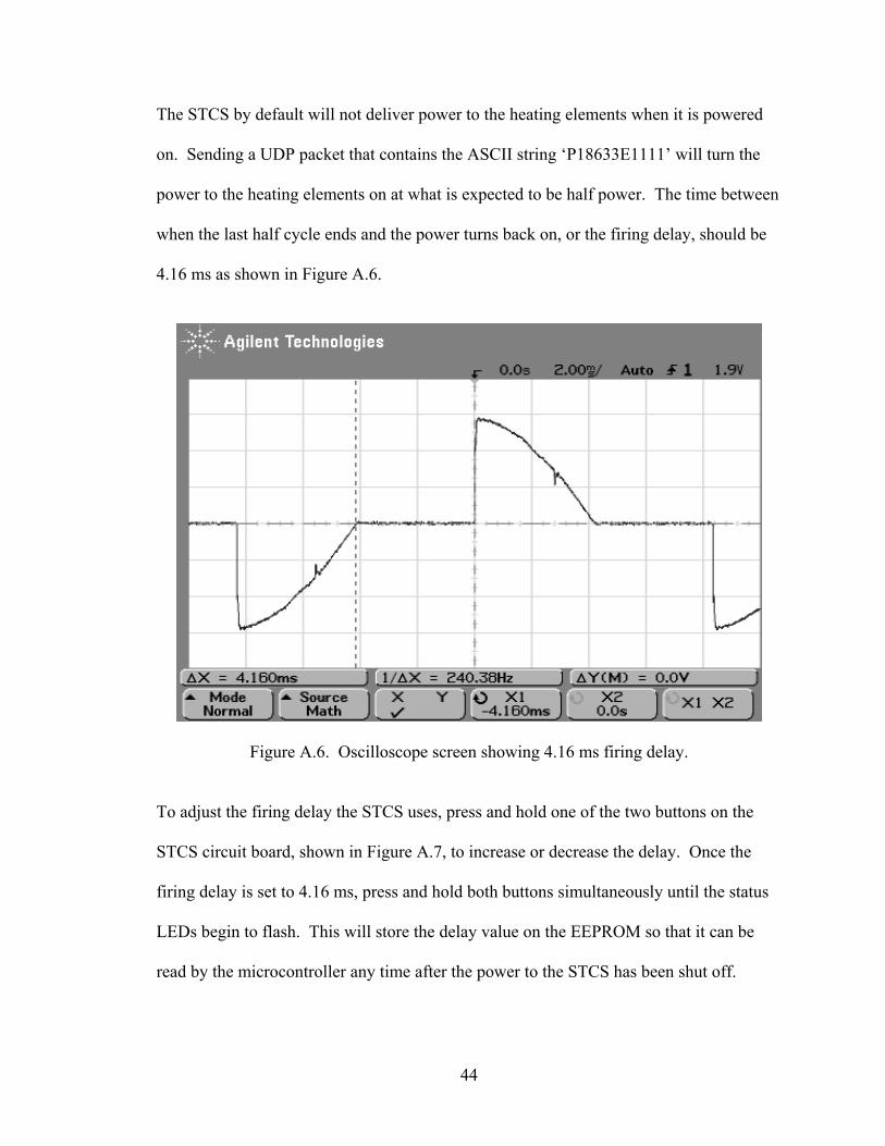
The STCS by default will not deliver power to the heating elements when it is powered
on. Sending a UDP packet that contains the ASCII string ‘P18633E1111’ will turn the
power to the heating elements on at what is expected to be half power. The time between
when the last half cycle ends and the power turns back on, or the firing delay, should be
4.16 ms as shown in Figure A.6.
Figure A.6. Oscilloscope screen showing 4.16 ms firing delay.
To adjust the firing delay the STCS uses, press and hold one of the two buttons on the
STCS circuit board, shown in Figure A.7, to increase or decrease the delay. Once the
firing delay is set to 4.16 ms, press and hold both buttons simultaneously until the status
LEDs begin to flash. This will store the delay value on the EEPROM so that it can be
read by the microcontroller any time after the power to the STCS has been shut off.

45
Figure A.7. Firing delay adjustment buttons.
To verify that the set up process completed correctly reset the power to the STCS and
resend the ASCII string ‘P18633E1111’. If the waveform on the oscilloscope matches
the waveform from before the power was reset, the set up process was completed the
value has been stored and the STCS is now ready for use.
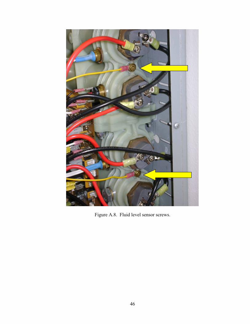
Maintaining the STCS
If the STCS is incorrectly reporting an error for fluid not being in the chambers
but fluid has been confirmed to be present, maintenance may need to be performed. The
fluid level sensor consists of a pair of screws that have current passed from one to the
other through the fluid. If water if present in the chambers of the STCS there will be a
path for the current to take and no error will be detected. Over time corrosion can build
up on the screws, blocking the current, which will appear to the microcontroller as if
water was not present. The maintenance procedure will require a TORX T-20
screwdriver to remove the fluid level sensor screws. Before proceeding make sure the
power to the system has been shut off and that there is no fluid in the chambers of the
STCS. Remove the screws shown in Figure A.8 and pull the quick disconnect ends of the
wires attached. Remove any oxidation from the ends of the screws and reinstall them
back in the STCS. Then reconnect the quick disconnect ends to their original locations.
Decrease Delay
Increase Delay
46
Figure A.8. Fluid level sensor screws.
47
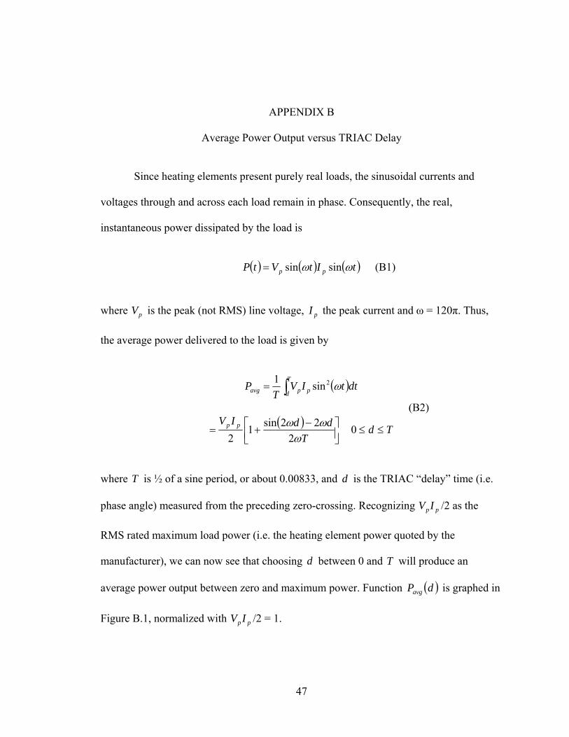
APPENDIX B
Average Power Output versus TRIAC Delay
Since heating elements present purely real loads, the sinusoidal currents and
voltages through and across each load remain in phase. Consequently, the real,
instantaneous power dissipated by the load is
( ) ( ) ( )tItVtP pp ωω sinsin= (B1)
where pV is the peak (not RMS) line voltage, pI the peak current and ω = 120π. Thus,
the average power delivered to the load is given by
( )∫=T
d ppavg dttIVT
P ω2sin1
(B2) ( )
⎥⎦⎤
⎢⎣⎡ −+=
TddIV pp
ωωω
222sin1
2 Td ≤≤0
where T is ½ of a sine period, or about 0.00833, and d is the TRIAC “delay” time (i.e.
phase angle) measured from the preceding zero-crossing. Recognizing pp IV /2 as the
RMS rated maximum load power (i.e. the heating element power quoted by the
manufacturer), we can now see that choosing d between 0 and T will produce an
average power output between zero and maximum power. Function ( )dPavg is graphed in
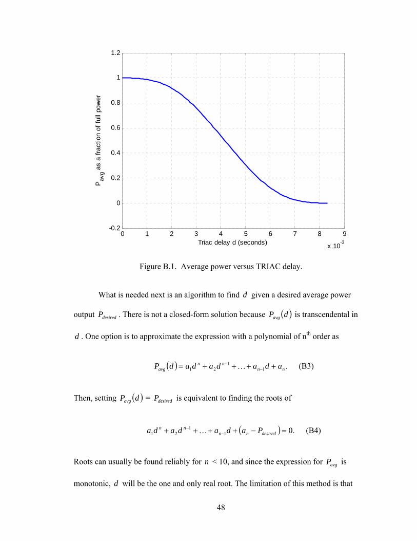
Figure B.1, normalized with pp IV /2 = 1.
48
0 1 2 3 4 5 6 7 8 9
x 10-3
-0.2
0
0.2
0.4
0.6
0.8
1
1.2
Triac delay d (seconds)
Pav
g as
a fra
ctio
n of
full
pow
er
Figure B.1. Average power versus TRIAC delay.
What is needed next is an algorithm to find d given a desired average power
output desiredP . There is not a closed-form solution because ( )dPavg is transcendental in
d . One option is to approximate the expression with a polynomial of nth order as
( ) .1
121 nn
nnavg adadadadP ++++= −
− K (B3)
Then, setting ( )dPavg = desiredP is equivalent to finding the roots of
( ) .011
21 =−++++ −−
desirednnnn Padadada K (B4)
Roots can usually be found reliably for n < 10, and since the expression for avgP is
monotonic, d will be the one and only real root. The limitation of this method is that
49
getting a good approximation of ( )dPavg may require a high-order polynomial involving
numerically very small or large numbers, and the error (the difference between the real
( )dPavg and its approximation) will also be a high-order polynomial and difficult to
predict. Root-finding algorithms may also exhibit numerical instabilities for high-order
polynomials.
Another approach is to iteratively solve for d given desiredP . This method is viable
because ( )dPavg is monotonic and its gradient always has the same sign. The algorithm
requires a guess for an initial solution 0d (say, 0d = 4.5 ms). Then,
( )[ ]desiredkavgdavg
kk PdPd
Pcdd
k−
∂
∂−=+1 (B5)
where c is a constant on the order of 10-5. The algorithm repeats until error ( )kavg dP -
desiredP becomes small enough. Note
( )⎥⎦⎤
⎢⎣⎡ −
=∂
∂
TdIV
dP ppavg 12cos
2ω (B6)
is always negative except at d = 0 and d = T (meaning that d = 0 or d = T are not
good initial guesses for the search algorithm). The benefit of this algorithm is that the
search error is under direct control and always known. The downside is that the algorithm
may require many iterations to solve for d near the tails of the avgP curve. However,
since there is little need to adjust power levels more often than once every few seconds
(or even once every 15 or 30 seconds), iteration count should not be a problem.

50
The analysis above also shows that a maximum allowable TRIAC phase angle
less than T is in fact not a serious limitation. Maximum delay d = 7.45ms corresponds
to about 0.8% of full power. In other words, a bank of four 4000W elements will have a
minimum average power output of 128W. If even finer control is necessary, three
elements may be switched off and a single one operated as low as 32W.
Converting d to a P number is simply a matter of multiplying d by the number
of 0.2 microsecond increments in 1 second and rounding to the nearest integer, i.e.
( )droundP ××= 6105 (B7)
51
APPENDIX C
Solar Thermal Collector Simulator Communication Standards
Summary
This document specifies the protocol that should be used to transmit data to, and receive
data from, the STCS. The STCS unit is an on-demand water heater that has been
modified to respond to external computer commands through a communication interface.
Thus, the STCS, in conjunction with an external computer controller, can be operated as
if it were a small solar thermal collector array.
Communication Standard
All communications with the STCS embedded controller are carried by standard Ethernet
UPD/IP packets over 10BASE-T wiring. Communication packet fields are defined next.
Packet fields carry ASCII strings designed to be human-readable, so that 3rd-party
UDP/IP transceivers can be used to help debug transmissions.
Heater Power Level (input received BY unit)
The STCS has four resistive heating elements fed by two input circuits. Users may
choose to install elements of various power levels, as long as each draws a maximum of
30 Amps RMS. Each individual element’s power level is controlled by a power TRIAC.
The TRIAC switches the element on at some point during each ½ cycle of AC input
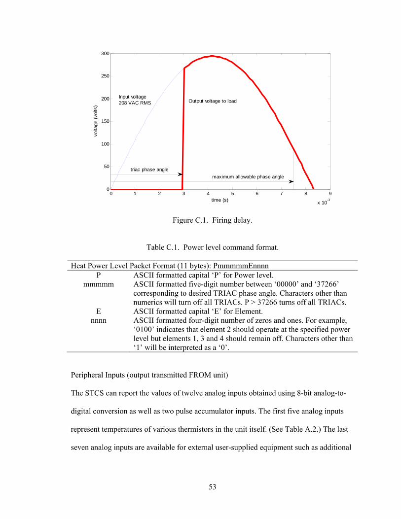
voltage, and switches it off at the next zero-crossing. (See Figure C.1.) The “on” point is
always measured relative to the previous zero-crossing, and is also known as the phase

52
angle. In this manner, the element’s average power ranges from nearly 100% (zero phase
angle) to nearly 0% (180 degree phase angle).
The STCS controller divides each ½ cycle into 41,666 increments. Each increment,
therefore, corresponds to 0.0432 degrees of phase angle, or 0.2 microseconds. Because
TRIACs cannot be reliably triggered too near a zero crossing, the largest allowable phase
angle is 880 microseconds before the next zero-crossing – in other words 7.453 ms (or
161 degrees) from the previous zero crossing. Thus, the power level communication
standard simply specifies an ASCII-formatted number ‘P’ between 0 and 37,266 along
with instructions about which element(s) to turn on. P specifies the number of 0.2
microsecond intervals from the preceding zero crossing, at which point the TRIACs will
conduct. Users should bear in mind that P = 0 corresponds to (virtually) no delay, or near
100% average power. (There is a slight delay while the TRIAC builds up enough gate
current to trigger.) P = 37,266 corresponds to 7.453 ms delay, or about 0.8% of full
power.
The ‘E’ symbol simply specifies (below) which elements are to be activated. At low
power levels, it is better to operate one element alone at, say, 12% power, rather than all
four at 3%. In this manner, the total output power of the STCS can be quite small, and the
effective power factor can be somewhat improved at low power levels.
Crafting algorithms to modulate the heater average power output involves inverting the
formula for fractional power as a function of TRIAC phase angle. This is discussed in
Appendix B.
53
0 1 2 3 4 5 6 7 8 9
x 10-3
0
50
100
150
200
250
300
time (s)
volta
ge (v
olts
)Input voltage208 VAC RMS Output voltage to load
triac phase anglemaximum allowable phase angle
Figure C.1. Firing delay.
Table C.1. Power level command format.
Heat Power Level Packet Format (11 bytes): PmmmmmEnnnnP ASCII formatted capital ‘P’ for Power level.
mmmmm ASCII formatted five-digit number between ‘00000’ and ‘37266’ corresponding to desired TRIAC phase angle. Characters other than numerics will turn off all TRIACs. P > 37266 turns off all TRIACs.
E ASCII formatted capital ‘E’ for Element. nnnn ASCII formatted four-digit number of zeros and ones. For example,
‘0100’ indicates that element 2 should operate at the specified power level but elements 1, 3 and 4 should remain off. Characters other than ‘1’ will be interpreted as a ‘0’.
Peripheral Inputs (output transmitted FROM unit)
The STCS can report the values of twelve analog inputs obtained using 8-bit analog-to-
digital conversion as well as two pulse accumulator inputs. The first five analog inputs
represent temperatures of various thermistors in the unit itself. (See Table A.2.) The last
seven analog inputs are available for external user-supplied equipment such as additional
54
thermistors, thermocouples, level sensors, etc. Two pulse accumulator ports are available
for reading flow-meter outputs.
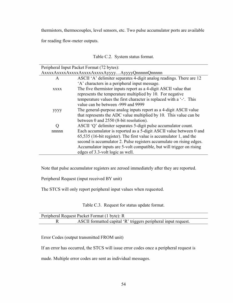
Table C.2. System status format.
Peripheral Input Packet Format (72 bytes): AxxxxAxxxxAxxxxAxxxxAxxxxAyyyy…AyyyyQnnnnnQnnnnn
A ASCII ‘A’ delimiter separates 4-digit analog readings. There are 12 ‘A’ characters in a peripheral input message.
xxxx The five thermistor inputs report as a 4-digit ASCII value that represents the temperature multiplied by 10. For negative temperature values the first character is replaced with a ‘-‘. This value can be between -999 and 9999
yyyy The general-purpose analog inputs report as a 4-digit ASCII value that represents the ADC value multiplied by 10. This value can be between 0 and 2550 (8-bit resolution).
Q ASCII ‘Q’ delimiter separates 5-digit pulse accumulator count. nnnnn Each accumulator is reported as a 5-digit ASCII value between 0 and
65,535 (16-bit register). The first value is accumulator 1, and the second is accumulator 2. Pulse registers accumulate on rising edges. Accumulator inputs are 5-volt compatible, but will trigger on rising edges of 3.3-volt logic as well.
Note that pulse accumulator registers are zeroed immediately after they are reported. Peripheral Request (input received BY unit)
The STCS will only report peripheral input values when requested.
Table C.3. Request for status update format.
Peripheral Request Packet Format (1 byte): R
R ASCII formatted capital ‘R’ triggers peripheral input request. Error Codes (output transmitted FROM unit)
If an error has occurred, the STCS will issue error codes once a peripheral request is
made. Multiple error codes are sent as individual messages.
55
Table C.4. Error message format.
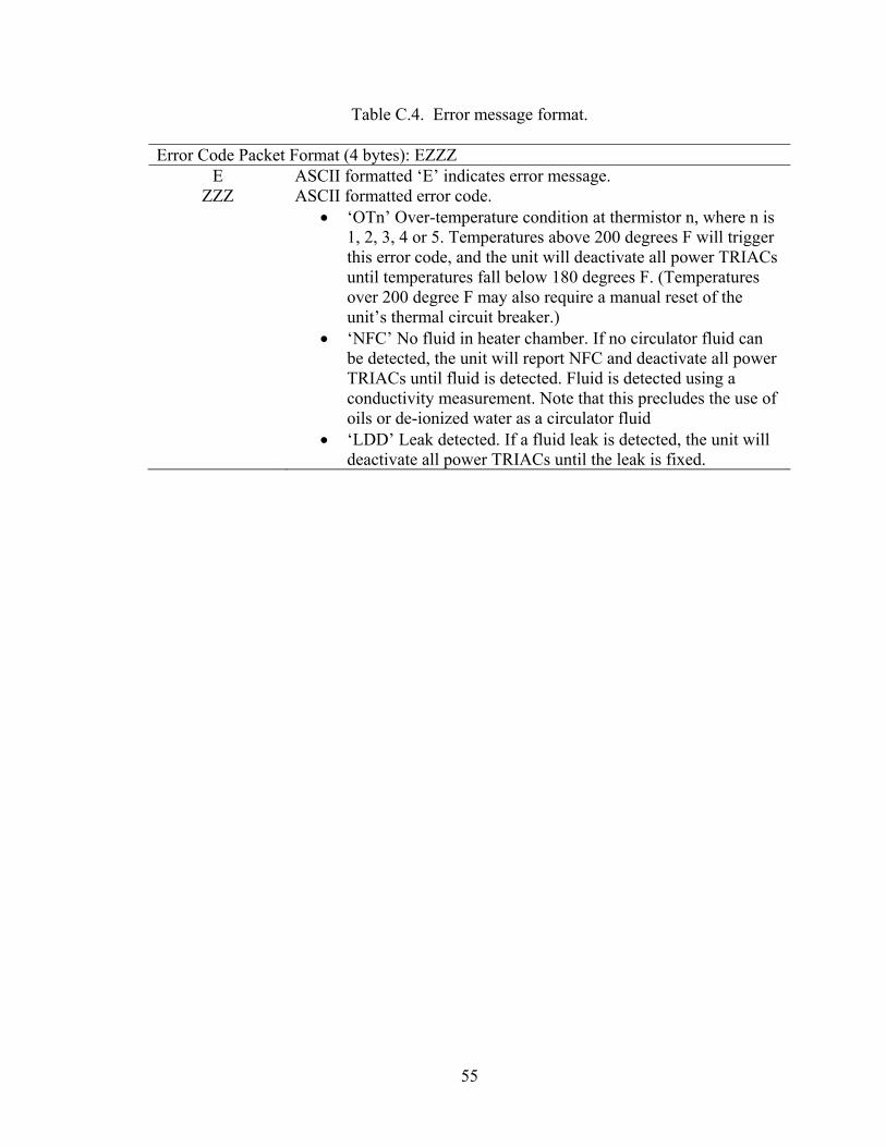
Error Code Packet Format (4 bytes): EZZZE ASCII formatted ‘E’ indicates error message.
ZZZ ASCII formatted error code. • ‘OTn’ Over-temperature condition at thermistor n, where n is
1, 2, 3, 4 or 5. Temperatures above 200 degrees F will trigger this error code, and the unit will deactivate all power TRIACs until temperatures fall below 180 degrees F. (Temperatures over 200 degree F may also require a manual reset of the unit’s thermal circuit breaker.)
• ‘NFC’ No fluid in heater chamber. If no circulator fluid can be detected, the unit will report NFC and deactivate all power TRIACs until fluid is detected. Fluid is detected using a conductivity measurement. Note that this precludes the use of oils or de-ionized water as a circulator fluid
• ‘LDD’ Leak detected. If a fluid leak is detected, the unit will deactivate all power TRIACs until the leak is fixed.
56
APPENDIX D
Available Insolation and Power
Available Insolation
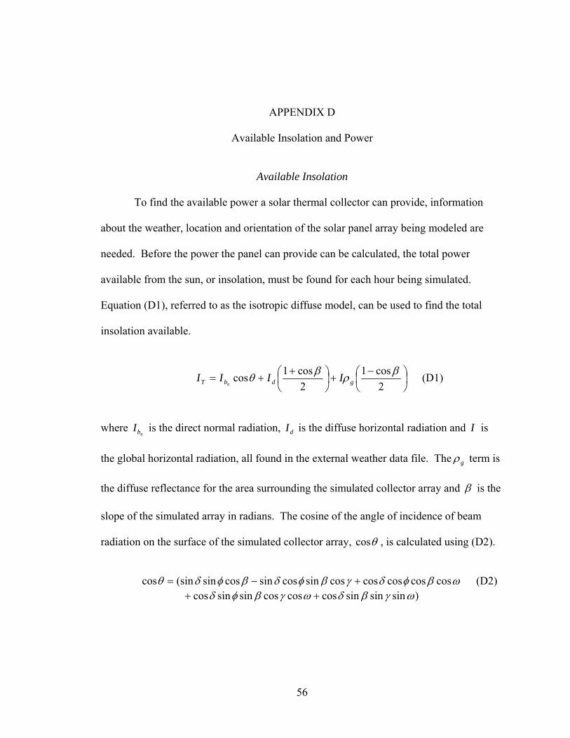
To find the available power a solar thermal collector can provide, information
about the weather, location and orientation of the solar panel array being modeled are
needed. Before the power the panel can provide can be calculated, the total power
available from the sun, or insolation, must be found for each hour being simulated.
Equation (D1), referred to as the isotropic diffuse model, can be used to find the total
insolation available.
⎟⎠⎞
⎜⎝⎛ −
+⎟⎠⎞
⎜⎝⎛ +
+=2cos1
2cos1cos βρβθ gdbT IIII
n (D1)
where nbI is the direct normal radiation, dI is the diffuse horizontal radiation and I is
the global horizontal radiation, all found in the external weather data file. The gρ term is
the diffuse reflectance for the area surrounding the simulated collector array and β is the
slope of the simulated array in radians. The cosine of the angle of incidence of beam
radiation on the surface of the simulated collector array, θcos , is calculated using (D2).
ωβφδγβφδβφδθ coscoscoscoscossincossincossin(sincos +−= (D2)
)sinsinsincoscoscossinsincos ωγβδωγβφδ ++
57
where φ is the latitude of the location of the simulated collector array in radians and γ is
the simulated surface array azimuth angle in radians. δ is the declination angle of the
sun, calculated by (D3) and ω is the hour angle which is calculated using (D4).
⎟⎠⎞
⎜⎝⎛ +
=365
2842sin180
45.23 dayππδ (D3)
where day is the number of the day of the year.
( )[ ] 1212412
−−−= dayTsolπω (D4)
where solT is the solar time of the year and is calculated using (D5).
( )
604 ELL
HrT locstyearsol
+−+= (D5)
where yearHr is the hour of the year, stL is the standard meridian for the local time zone
in radians, locL is the longitude of the location of the simulated collector array in radians
and E is referred to as the equation of time and is calculated by (D6).
BBE sin032077.0cos001868.0000075.0(2.229 −+= (D6)
)2sin04089.02cos014615.0 BB −−
where B is a value that is calculated using (D7).
( )36521 π
−= dayB (D7)

58
Available Power
The available insolation is assumed to remain constant for an hour, thus is only
calculated at the beginning of each hour of the simulation. Once the hourly insolation has
been calculated the simulated panel array parameters are used to find the amount of
power that will theoretically be provided to the fluid. This theoretical power is called the
useful power, and is calculated using (D8).
( )( )aiLRnRTcu TTUFFKGAQ
useuseuse−−= )(τατα (D8)
where
usecA is the area of the collector array being modeled, iT is the temperature of the
fluid at the inlet of the collector array and aT is the ambient temperature around the array.
TG is the total irradiance per unit area in units of 2mW , given by (D9), and ταK is the
incidence angle modifier for the radiation incident on the surface of the array, which is
calculated using (D10). usenRF )(τα is the y-intercept value of the efficiency equation that
has been modified to reflect the difference between the flow rate used in the rating
process and the flow rate used in the simulation test. It is calculated using (D11).
useLRUF is the slope value of the efficiency equation, also modified to reflect the
difference in flow rates. This value is given by (D12).
6.3
TT
IG = (D9)
⎟⎠⎞
⎜⎝⎛ −−= 1
cos11 0 θτα bK (D10)

59
where 0b is a constant called the incidence angle modifier coefficient and can be found
on the SRCC Certification and Rating sheet for the panel being simulated under the
Incident Angle Modifier section. On the rating sheet the value is usually given as a
negative value but (D10) needs 0b as a positive value.
testuse nRnR FrF )()( τατα ×= (D11)
where
testnRF )(τα is the y-intercept value for the efficiency equation given on the SRCC
Certification and Rating sheet for the collector. r is the ratio by which the y-intercept
and slope of the efficiency equation are to be corrected for the difference in flow rate as
is given by (D13).
testuse LRLR UFrUF ×= (D12)
where
testLRUF is the slope value for the efficiency equation given on the rating sheet for
the collector. This value is usually given as negative, but (D12) requires a positive value.
⎥⎥⎦
⎤
⎢⎢⎣
⎡⎟⎟⎠
⎞⎜⎜⎝
⎛ ×−−
×
⎥⎥⎦
⎤
⎢⎢⎣
⎡⎟⎟⎠
⎞⎜⎜⎝
⎛ ×−−
×=
ptest
Lc
Lc
ptest
puse
Lc
Lc
puse
cmUFA
UFAcm
cmUFA
UFAcm
rtest
test
use
use
&
&
&
&
'exp1
'
'exp1
' (D13)
where usem& is the flow rate of the fluid used in the simulation and testm& is the flow rate
used in the rating process which is given on the rating sheet. pc is the specific heat of the
fluid used and testcA is the area of the collector used in the rating process, given on the
60
rating sheet. LUF ' is the simulated collector fin efficiency multiplied by the overall loss
coefficient of the collector. This value can be calculated using (D14).
⎟⎟
⎠
⎞
⎜⎜
⎝
⎛ ×−−=
ptest
cLR
c
ptestL cm
AUFA
cmUF testtest
test&
&1ln' (D14)
This useful power, uQ , is the power that is sent to the STCS to be output to the fluid.
The actual output power differs from the useful power in both an actual panel array and
in the STCS. Actual output power is calculated using (D15).
( )iopuseout TTcmQ −= & (D15)
where oT is the outlet temperature of the collector array or of the STCS. Since the useful
power depends on two external variables, usem& and iT , it can vary, and thus needs to be
calculated much more frequently than the hourly insolation.
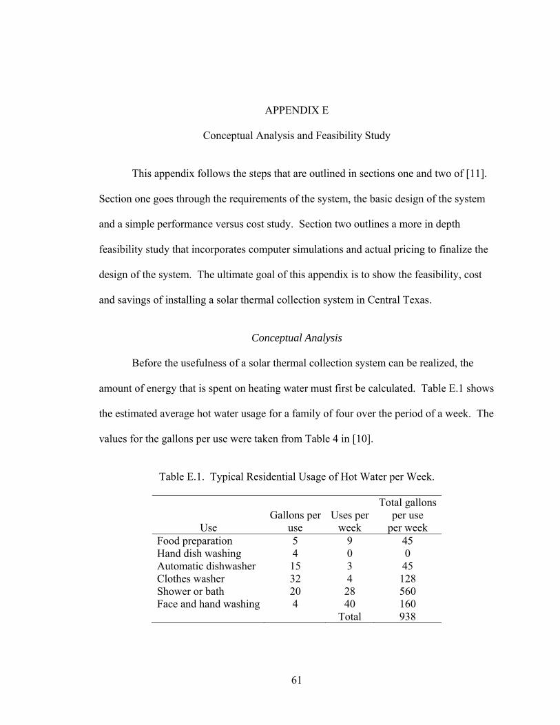
61
APPENDIX E
Conceptual Analysis and Feasibility Study
This appendix follows the steps that are outlined in sections one and two of [11].
Section one goes through the requirements of the system, the basic design of the system
and a simple performance versus cost study. Section two outlines a more in depth
feasibility study that incorporates computer simulations and actual pricing to finalize the
design of the system. The ultimate goal of this appendix is to show the feasibility, cost
and savings of installing a solar thermal collection system in Central Texas.
Conceptual Analysis
Before the usefulness of a solar thermal collection system can be realized, the
amount of energy that is spent on heating water must first be calculated. Table E.1 shows
the estimated average hot water usage for a family of four over the period of a week. The
values for the gallons per use were taken from Table 4 in [10].
Table E.1. Typical Residential Usage of Hot Water per Week.
Use
Gallons per
use
Uses per
week
Total gallons per use
per week Food preparation 5 9 45 Hand dish washing 4 0 0 Automatic dishwasher 15 3 45 Clothes washer 32 4 128 Shower or bath 20 28 560 Face and hand washing 4 40 160 Total 938
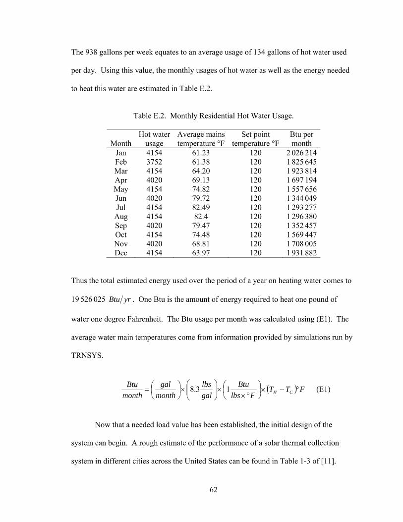
62
The 938 gallons per week equates to an average usage of 134 gallons of hot water used
per day. Using this value, the monthly usages of hot water as well as the energy needed
to heat this water are estimated in Table E.2.
Table E.2. Monthly Residential Hot Water Usage.
Month Hot water
usage Average mains temperature °F
Set point temperature °F
Btu per month
Jan 4154 61.23 120 2 026 214 Feb 3752 61.38 120 1 825 645 Mar 4154 64.20 120 1 923 814 Apr 4020 69.13 120 1 697 194 May 4154 74.82 120 1 557 656 Jun 4020 79.72 120 1 344 049 Jul 4154 82.49 120 1 293 277
Aug 4154 82.4 120 1 296 380 Sep 4020 79.47 120 1 352 457 Oct 4154 74.48 120 1 569 447 Nov 4020 68.81 120 1 708 005 Dec 4154 63.97 120 1 931 882
Thus the total estimated energy used over the period of a year on heating water comes to
19 526 025 yrBtu . One Btu is the amount of energy required to heat one pound of
water one degree Fahrenheit. The Btu usage per month was calculated using (E1). The
average water main temperatures come from information provided by simulations run by
TRNSYS.
( ) FTTFlbs
Btugallbs
monthgal
monthBtu
CH °−×⎟⎠⎞
⎜⎝⎛
°××⎟⎟⎠
⎞⎜⎜⎝
⎛×⎟⎠⎞
⎜⎝⎛= 13.8 (E1)
Now that a needed load value has been established, the initial design of the
system can begin. A rough estimate of the performance of a solar thermal collection
system in different cities across the United States can be found in Table 1-3 of [11].
63
Since Waco, Texas is not found in the table, the performance values for collectors in Fort
Worth, Texas are used. The average flat plate collector receives 186 000 ( )yrftBtu ×2 ,
which is a worst case estimate. Using this average performance value an initial collector
size can be estimated using (E2) where Load is the estimated annual load, annualP is the
expected annual performance, and F is the solar fraction, which is the percentage of the
total load that is expected to be offset by the solar collector system. The value
recommended in [11] for F is 0.64.
⎟⎟⎠
⎞⎜⎜⎝
⎛×
×⎟⎟⎠
⎞⎜⎜⎝
⎛
=
yrftBtuP
Fyr
BtuloadA
annual
c
2
(E2)
Using the value for Load calculated from Table E.2 and annualP from Table 1-3 in [11],
the area of the collector array is calculated to be 67.19 ft2, which is then rounded up to
nearest square foot. The storage requirements for the system are estimated using the
method shown in [11] of 1 gallon on storage per ft2 of collector, thus the initial estimation
for the storage tank is 68 gallons.
A preliminary system cost estimate can be performed to give a basic idea of how
much the collector system will cost. The minimum and maximum costs for the system
can be calculated by adjusting the values found in [11] for inflation from 1987 to 2008.
Equation (E3) shows the method used to give the upper and lower bounds of the cost
estimate for the system, where cA is the calculated area of the collector. The minimum
cost for the system is $5236 and the maximum cost is $10,472. A representative 40 ft2
64
collector costs around $1000, which is less than 30% of the minimum system cost, thus
the cost estimate is acceptable.
cAftC ×= 2
min 77$ (E3)
cAftC ×= 2max 154$
The cost-effectiveness of the system can be analyzed by calculating the payback
period and the allowable first cost for the system. The payback period involves
comparing the estimated annual output of the collector system with the price of the
energy that will be offset. Equation (E4) can be used to find the annual output give the
estimated annual performance annualP , and the calculated area of the collector cA .
cannual APoutput ×= (E4)
The system being designed would have an estimated annual output of
12 648 000 yrBtu . The cost of generating this heat energy without the use of the
collector system depends on the source of energy used, the price of that energy and the
efficiency η of the system that is used to heat the water. The two main choices for
energy to heat water in Waco, Texas are natural gas and electricity. As of October 2008,
natural gas cost $45.29 per million Btu and electricity cost $40.96 per million Btu. A
system that uses natural gas for heating has an average efficiency of 60% while electrical
systems have a much higher efficiency, around 95%. This lower efficiency means that
more fuel will be needed to generate the same amount of heat. Equation (E5) is used to
calculate the annual savings from using the collector system for both natural gas and
electrical systems.
65
priceoutputsavings ×=η
(E5)
The greatest savings would be realized if the collector system were used to augment a
natural gas system, due to its higher price and lower efficiency. For the system described
here the savings with a natural gas system would be $954.63 per year and the savings
with an electrical system would be $545.34 per year. Using the minimum and maximum
cost estimation from (E3) and the annual savings from (E5) the minimum and maximum
number of years required to pay back the cost of the system can be calculated. Equation
(E6) can be used to find the minimum and maximum payback period for both energy
sources.
savings
Cpayback = (E6)
The system being designed to augment a natural gas system has a minimum payback
period of 5.5 years and a maximum payback period of 11 years. If the system being
designed is augmenting an electrical system, the minimum payback period is raised to 9.6
years and the maximum payback period to 19.2 years. The allowable first cost for the
system takes into account the annual savings from using the collector system and an
economic factor (EF) that can be found in Table 1-5 in [11]. The economic life of the
system is planned to be 20 years, with 10% interest rate and factoring in a 2.5% per year
fuel price change. Using these values the system will have an economic factor of 10.337.
EFsavingsC first ×= (E7)
66
Using (E7), the allowable first cost for the system that augments the natural gas
configuration will be $9868.03, and $5637.20 for the system that augments the electrical
configuration. Since both of these are between the minimum and maximum cost
estimates of the system, the system will be cost effective.
Feasibility Study
In order to more accurately determine the feasibility of a solar thermal collector
system, computer simulations are used to find the energy available from a system and
actual costs for a representative system are calculated. TRNSYS was used to model a
two-tank system and the simulated energy output was compared to the theoretical energy
required for the residence. Figure E.1 shows the simulation layout that was used for the
system. The system uses two 40ft2 solar collectors, a collection tank with an integrated
heat exchanger to hold the heat energy from the panels, a conventional water heater that
is fed from the solar collection tank and a pump to circulate the heating fluid through the
collectors. This same simulation design is used for both the solar system that augments
an electrical powered water heater and the system that augments a gas power heater, the
only difference is the way the conventional water heater is configured in the simulation.
Table E.3 contains the results from the simulation run that uses the electrical
conventional water heater. In a realistic application the months when the solar fraction is
99% would represent the auxiliary heater not needing to be used.
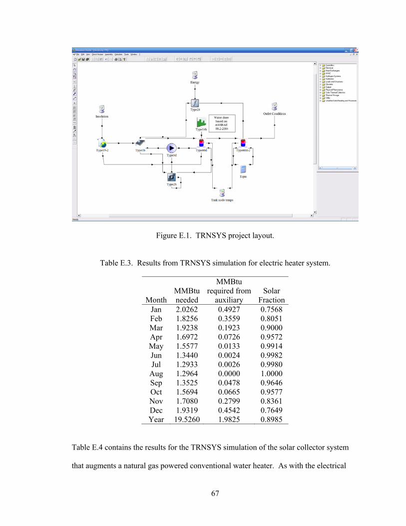
67
Figure E.1. TRNSYS project layout.
Table E.3. Results from TRNSYS simulation for electric heater system.
Month
MMBtu needed
MMBtu required from
auxiliary
Solar
FractionJan 2.0262 0.4927 0.7568 Feb 1.8256 0.3559 0.8051 Mar 1.9238 0.1923 0.9000 Apr 1.6972 0.0726 0.9572 May 1.5577 0.0133 0.9914 Jun 1.3440 0.0024 0.9982 Jul 1.2933 0.0026 0.9980
Aug 1.2964 0.0000 1.0000 Sep 1.3525 0.0478 0.9646 Oct 1.5694 0.0665 0.9577 Nov 1.7080 0.2799 0.8361 Dec 1.9319 0.4542 0.7649 Year 19.5260 1.9825 0.8985
Table E.4 contains the results for the TRNSYS simulation of the solar collector system
that augments a natural gas powered conventional water heater. As with the electrical
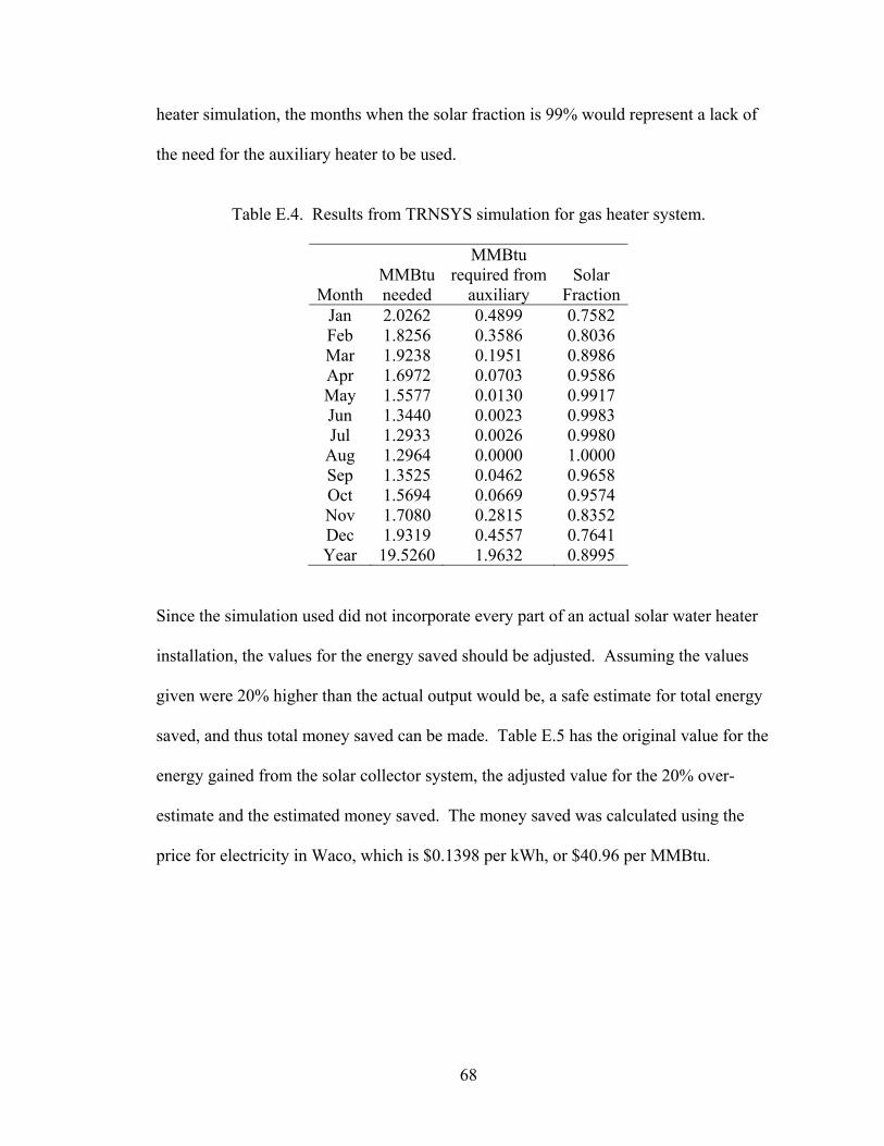
68
heater simulation, the months when the solar fraction is 99% would represent a lack of
the need for the auxiliary heater to be used.
Table E.4. Results from TRNSYS simulation for gas heater system.
Month
MMBtu needed
MMBtu required from
auxiliary
Solar
FractionJan 2.0262 0.4899 0.7582 Feb 1.8256 0.3586 0.8036 Mar 1.9238 0.1951 0.8986 Apr 1.6972 0.0703 0.9586 May 1.5577 0.0130 0.9917 Jun 1.3440 0.0023 0.9983 Jul 1.2933 0.0026 0.9980
Aug 1.2964 0.0000 1.0000 Sep 1.3525 0.0462 0.9658 Oct 1.5694 0.0669 0.9574 Nov 1.7080 0.2815 0.8352 Dec 1.9319 0.4557 0.7641 Year 19.5260 1.9632 0.8995
Since the simulation used did not incorporate every part of an actual solar water heater
installation, the values for the energy saved should be adjusted. Assuming the values
given were 20% higher than the actual output would be, a safe estimate for total energy
saved, and thus total money saved can be made. Table E.5 has the original value for the
energy gained from the solar collector system, the adjusted value for the 20% over-
estimate and the estimated money saved. The money saved was calculated using the
price for electricity in Waco, which is $0.1398 per kWh, or $40.96 per MMBtu.
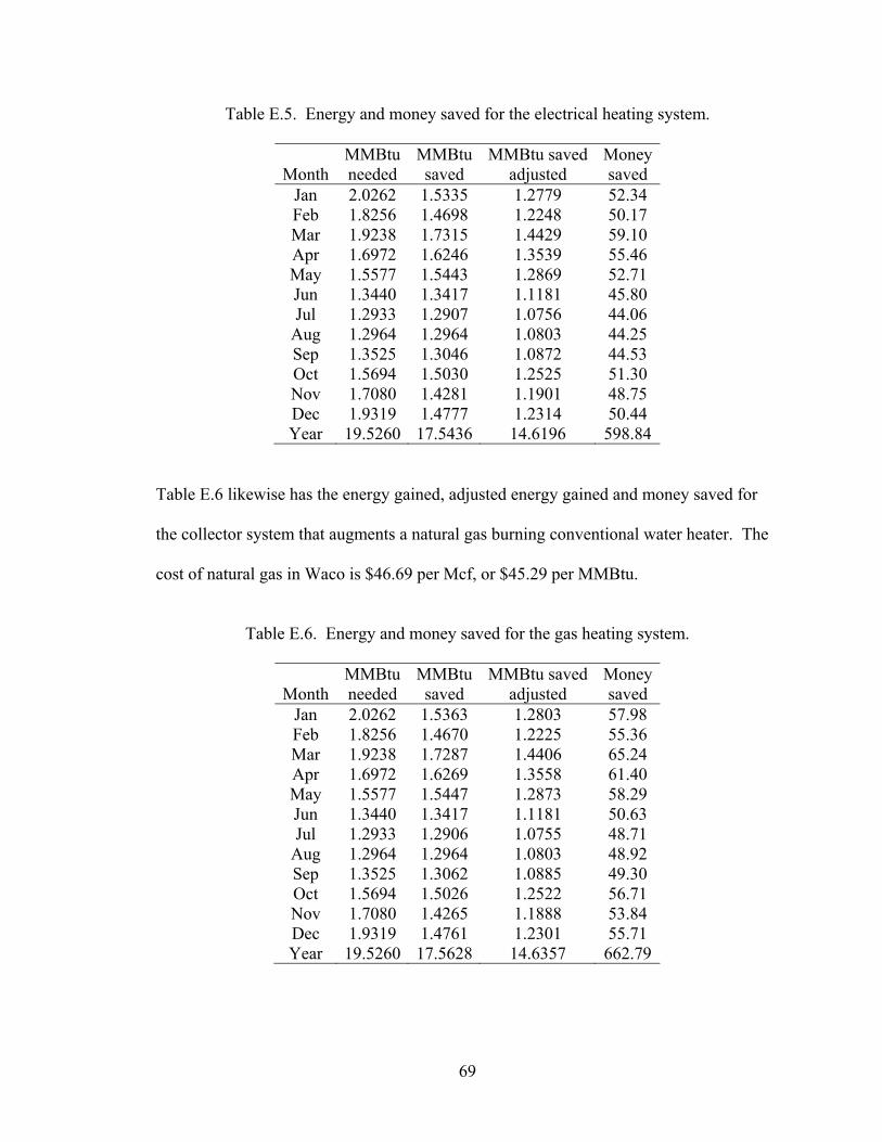
69
Table E.5. Energy and money saved for the electrical heating system.
Month
MMBtu needed
MMBtu saved
MMBtu savedadjusted
Money saved
Jan 2.0262 1.5335 1.2779 52.34 Feb 1.8256 1.4698 1.2248 50.17 Mar 1.9238 1.7315 1.4429 59.10 Apr 1.6972 1.6246 1.3539 55.46 May 1.5577 1.5443 1.2869 52.71 Jun 1.3440 1.3417 1.1181 45.80 Jul 1.2933 1.2907 1.0756 44.06
Aug 1.2964 1.2964 1.0803 44.25 Sep 1.3525 1.3046 1.0872 44.53 Oct 1.5694 1.5030 1.2525 51.30 Nov 1.7080 1.4281 1.1901 48.75 Dec 1.9319 1.4777 1.2314 50.44 Year 19.5260 17.5436 14.6196 598.84
Table E.6 likewise has the energy gained, adjusted energy gained and money saved for
the collector system that augments a natural gas burning conventional water heater. The
cost of natural gas in Waco is $46.69 per Mcf, or $45.29 per MMBtu.
Table E.6. Energy and money saved for the gas heating system.
Month
MMBtu needed
MMBtu saved
MMBtu savedadjusted
Money saved
Jan 2.0262 1.5363 1.2803 57.98 Feb 1.8256 1.4670 1.2225 55.36 Mar 1.9238 1.7287 1.4406 65.24 Apr 1.6972 1.6269 1.3558 61.40 May 1.5577 1.5447 1.2873 58.29 Jun 1.3440 1.3417 1.1181 50.63 Jul 1.2933 1.2906 1.0755 48.71
Aug 1.2964 1.2964 1.0803 48.92 Sep 1.3525 1.3062 1.0885 49.30 Oct 1.5694 1.5026 1.2522 56.71 Nov 1.7080 1.4265 1.1888 53.84 Dec 1.9319 1.4761 1.2301 55.71 Year 19.5260 17.5628 14.6357 662.79
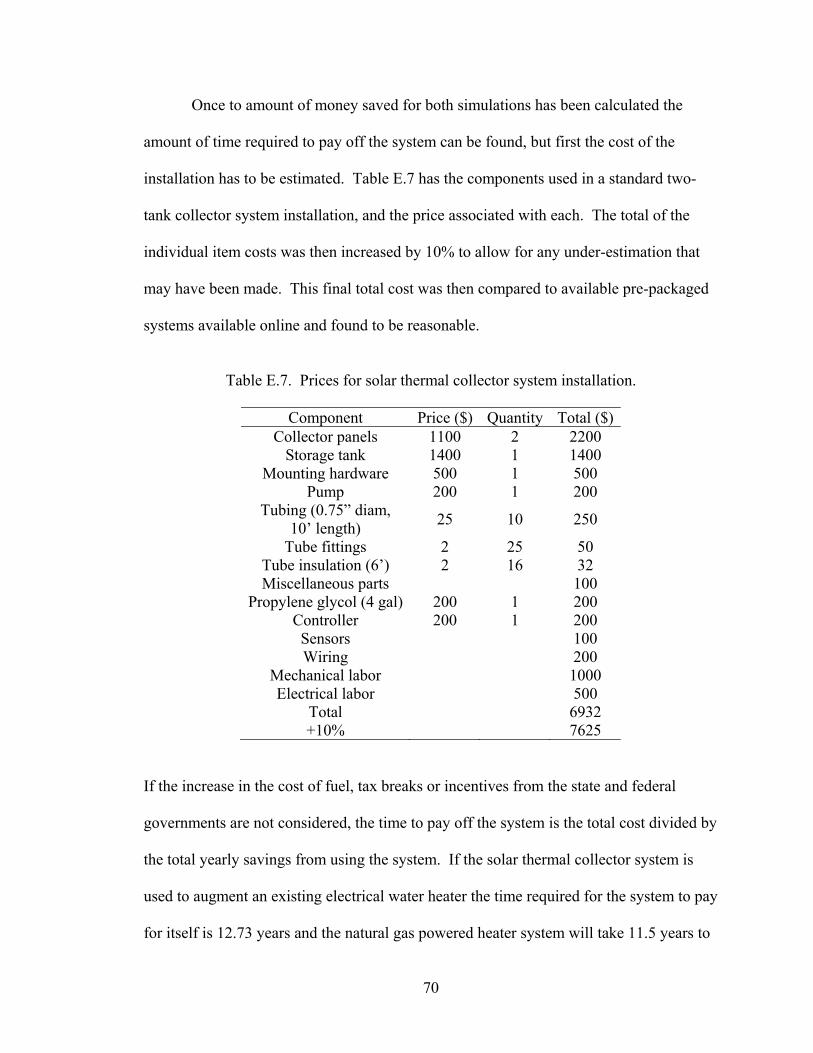
70
Once to amount of money saved for both simulations has been calculated the
amount of time required to pay off the system can be found, but first the cost of the
installation has to be estimated. Table E.7 has the components used in a standard two-
tank collector system installation, and the price associated with each. The total of the
individual item costs was then increased by 10% to allow for any under-estimation that
may have been made. This final total cost was then compared to available pre-packaged
systems available online and found to be reasonable.
Table E.7. Prices for solar thermal collector system installation.
Component Price ($) Quantity Total ($)
Collector panels 1100 2 2200 Storage tank 1400 1 1400
Mounting hardware 500 1 500 Pump 200 1 200
Tubing (0.75” diam, 10’ length) 25 10 250
Tube fittings 2 25 50 Tube insulation (6’) 2 16 32 Miscellaneous parts 100
Propylene glycol (4 gal) 200 1 200 Controller 200 1 200 Sensors 100 Wiring 200
Mechanical labor 1000 Electrical labor 500
Total 6932 +10% 7625
If the increase in the cost of fuel, tax breaks or incentives from the state and federal
governments are not considered, the time to pay off the system is the total cost divided by
the total yearly savings from using the system. If the solar thermal collector system is
used to augment an existing electrical water heater the time required for the system to pay
for itself is 12.73 years and the natural gas powered heater system will take 11.5 years to
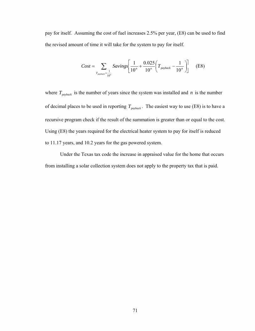
71
pay for itself. Assuming the cost of fuel increases 2.5% per year, (E8) can be used to find
the revised amount of time it will take for the system to pay for itself.
∑=
⎥⎦
⎤⎢⎣
⎡⎟⎠⎞
⎜⎝⎛ −+=
npaybackTnpaybacknn TSavingsCost
101 10
110025.0
101 (E8)
where paybackT is the number of years since the system was installed and n is the number
of decimal places to be used in reporting paybackT . The easiest way to use (E8) is to have a
recursive program check if the result of the summation is greater than or equal to the cost.
Using (E8) the years required for the electrical heater system to pay for itself is reduced
to 11.17 years, and 10.2 years for the gas powered system.
Under the Texas tax code the increase in appraised value for the home that occurs
from installing a solar collection system does not apply to the property tax that is paid.

72
APPENDIX F
Uncertainty Calculations
Method Used to Find Uncertainties
The methods used for calculating the uncertainty in the power output are outlined
by Moffat [5]. Uncertainty refers to a possible value that an error may have while the
term error refers to the difference between the measured value and the true value. There
are two types of uncertainty, fixed and random. Fixed uncertainty is due to the
uncertainty in the measuring tool being used. It is usually specified by the manufacturer,
but if no value is given the uncertainty can be assumed to be one-half of the smallest unit
of measurement. Random uncertainty is due to variability in testing. Reporting the
uncertainty of the output value is more commonly accepted than the error due to the
inability to know the actual value that the measured value is representing. The method
involves taking the root-sum-square combination of terms that represent the uncertainty
of various inputs to the equation that calculates the output power. The calculations used
to find the uncertainties in the different parts of the STCS can be found later in this
appendix. The power output to the water is calculated using (F1).
( )iopout TTcmQ −= & (F1)
Flow rate, m& , outlet temperature, oT and inlet temperature, iT , are the three variables that
have to measured in the system to calculate (F1). To find the total uncertainty of the
system the uncertainty of each variable that is measured must be calculated.
73
The flow rate during the experiments shown in this thesis was reported by a flow
meter measuring the flow of the system. The meter sends a pulse to the STCS when 0.05
gallons have flowed through it. There are two fixed uncertainties associated with using
this flow meter, the uncertainty of the flow sensor and the uncertainty of the sensor
reader. The uncertainty in the measurement of the flow rate is given by (F2).
22
readersensorm BBU +=& (F2)
The flow sensor has a reported accuracy of 1% of full range. For the system the flow
meter is being used in with the tests, full range is skg73745.1 , so sensorB is
skg0173745.0 . The flow sensor outputs a signal that has increases its frequency the
faster the fluid is flowing through it. The frequency output is 15 Hz for every
skg08687.0 . The sensor reader has an accuracy of 0.5 Hz, so readerB is skg00290.0 .
With these uncertainties combined the overall uncertainty associated with measuring the
flow rate comes out to skg0176.0 .
The other two inputs, oT and iT were calibrated in two parts, the thermistors and
the ADC that reports the value corresponding to the value of the thermistor. The
thermistors were calibrated by measuring the temperature of water in a container with a
thermocouple and measuring the resistance value of the thermistors in the water. This
process was done at freezing and at room temperature, with six trials recorded for each.
The thermocouple used had a fixed uncertainty, tcB , of 0.11°C and the thermocouple
reader used had a fixed uncertainty, readtcB , , of 1.0005°C. The thermistors are quoted to
have a specified temperature accuracy of 0.5%, thus their fixed uncertainty, thermB , will

74
depend on the resistance value the thermistor has for temperature. For oT , thermB is
55.495 ohms, and for iT , thermB is 55.63 ohms. The ohmmeter that was used to measure
the resistance of the thermistors has a fixed uncertainty, readthermB , , of 33.317 ohms for oT ,
and 33.398 ohms for iT . The total fixed uncertainty in calibrating iT and oT , given by
(F3), is 64.885 ohms for iT , and 64.728 ohms for oT .
2
,2
, readthermthermcaltherm BBB += (F3)
These resistance values correspond to temperature values if the Steinhart-Hart equation
for the thermistor is applied. Using this method, calthermB , becomes 0.131°C for iT , and
0.130°C for oT . Combining the two fixed uncertainties from using the thermocouple and
thermocouple reader with the uncertainty of the thermistor calibration will give the
overall fixed uncertainty for the thermistors. Equation (F4) gives the overall
uncertainties of both iT and oT to be 1.015°C.
2
,2
,2
calthermreadtctcT BBBB ++= (F4)
The ADC unit was calibrated using a resistance decade box to simulate the resistance for
iT and oT . The resistance was measured with an ohmmeter and recorded, along with the
temperature reported back by the STCS for ten trials. The decade box had a fixed
uncertainty, decadeB , of half its smallest increment, or 0.5 ohms. The ohmmeter had a
fixed uncertainty, ohmmeterB , of 31.283 ohms for iT , and 31.214 ohms for oT . The random
uncertainty in the trials can be calculated using (F5).
75
n
TS n
ADCσ×
= (F5)
where nT is the Student’s t value for n-samples, σ is the standard deviation of the data
and n is the number of samples taken. For iT , ADCS is 0.282 ohms and for oT , ADCS is
0.658 ohms. Equation (F6) combines the fixed uncertainties for the decade box and the
ohmmeter with the random uncertainty of the measurements to get the uncertainty of the
resistance, resB .
222
ADCohmmeterdecaderes SBBB ++= (F6)
resB for iT is 31.288 ohms and 31.225 ohms for oT . These resistance values correspond
to 0.0689°C for iT , and 0.0692°C for oT . The error in the reported temperature,
tempADCB , , is combined with the uncertainty from the resistance used, resB , to get the
overall uncertainty for the ADC. Using (F7) the uncertainty for the iT as reported by the
ADC unit is 0.0689°C, and 1.006°C for oT .
22
, restempADCADC BBB += (F7)
Once the uncertainties for the thermistors and the ADC unit have been calculated, the
total uncertainty for the inlet and outlet temperatures can be found using (F8). iT has a
total uncertainty of 1.0174°C and oT has a total uncertainty of 1.429°C.
22
ADCTT BBU += (F8)
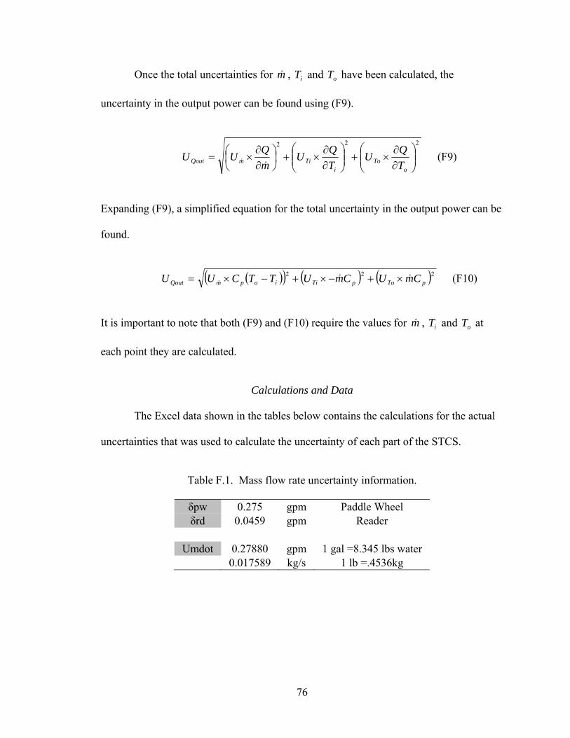
76
Once the total uncertainties for m& , iT and oT have been calculated, the
uncertainty in the output power can be found using (F9).
222
⎟⎟⎠
⎞⎜⎜⎝
⎛∂∂
×+⎟⎟⎠
⎞⎜⎜⎝
⎛∂∂
×+⎟⎠⎞
⎜⎝⎛
∂∂
×=o
Toi
TimQout TQU
TQU
mQUU&
& (F9)
Expanding (F9), a simplified equation for the total uncertainty in the output power can be
found.
( )( ) ( ) ( )222
pTopTiiopmQout CmUCmUTTCUU &&& ×+−×+−×= (F10)
It is important to note that both (F9) and (F10) require the values for m& , iT and oT at
each point they are calculated.
Calculations and Data
The Excel data shown in the tables below contains the calculations for the actual
uncertainties that was used to calculate the uncertainty of each part of the STCS.
Table F.1. Mass flow rate uncertainty information.
δpw 0.275 gpm Paddle Wheel δrd 0.0459 gpm Reader
Umdot 0.27880 gpm 1 gal =8.345 lbs water 0.017589 kg/s 1 lb =.4536kg
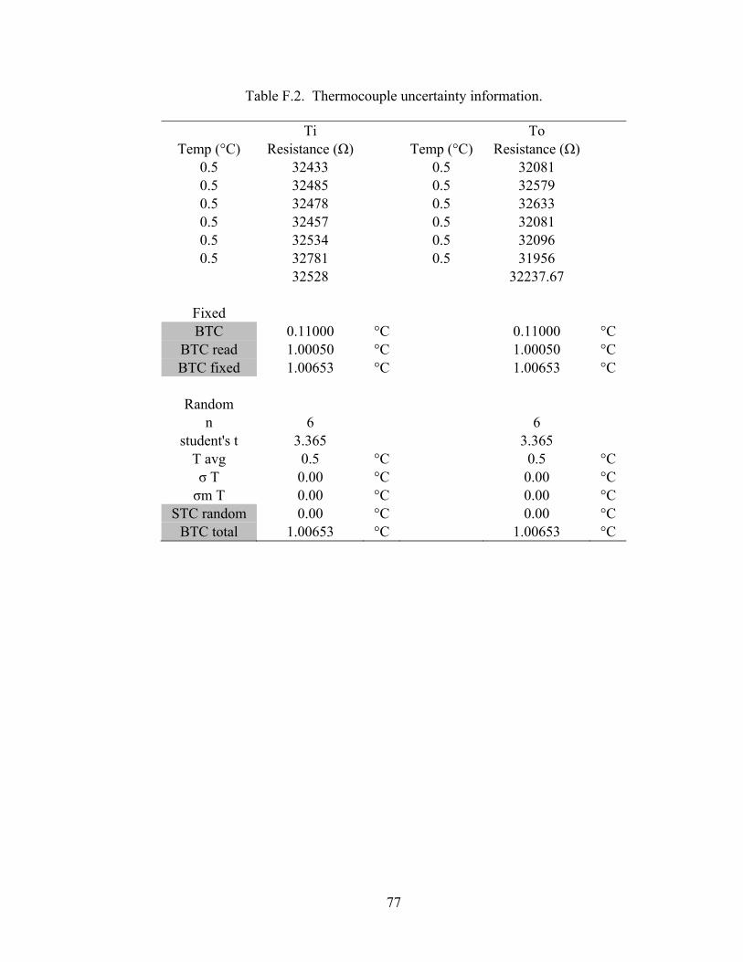
77
Table F.2. Thermocouple uncertainty information.
Ti To Temp (°C) Resistance (Ω) Temp (°C) Resistance (Ω)
0.5 32433 0.5 32081 0.5 32485 0.5 32579 0.5 32478 0.5 32633 0.5 32457 0.5 32081 0.5 32534 0.5 32096 0.5 32781 0.5 31956
32528 32237.67
Fixed BTC 0.11000 °C 0.11000 °C
BTC read 1.00050 °C 1.00050 °C BTC fixed 1.00653 °C 1.00653 °C
Random
n 6 6 student's t 3.365 3.365
T avg 0.5 °C 0.5 °C σ T 0.00 °C 0.00 °C σm T 0.00 °C 0.00 °C
STC random 0.00 °C 0.00 °C BTC total 1.00653 °C 1.00653 °C
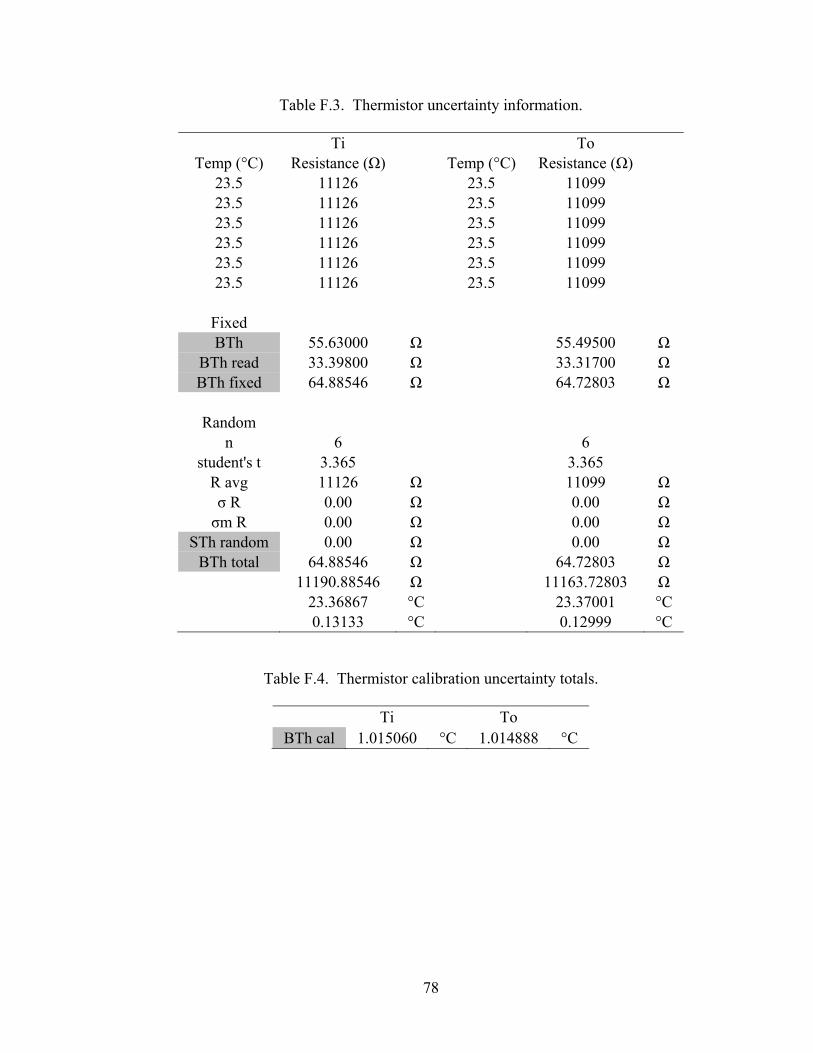
78
Table F.3. Thermistor uncertainty information.
Ti To Temp (°C) Resistance (Ω) Temp (°C) Resistance (Ω)
23.5 11126 23.5 11099 23.5 11126 23.5 11099 23.5 11126 23.5 11099 23.5 11126 23.5 11099 23.5 11126 23.5 11099 23.5 11126 23.5 11099
Fixed BTh 55.63000 Ω 55.49500 Ω
BTh read 33.39800 Ω 33.31700 Ω BTh fixed 64.88546 Ω 64.72803 Ω
Random
n 6 6 student's t 3.365 3.365
R avg 11126 Ω 11099 Ω σ R 0.00 Ω 0.00 Ω σm R 0.00 Ω 0.00 Ω
STh random 0.00 Ω 0.00 Ω BTh total 64.88546 Ω 64.72803 Ω
11190.88546 Ω 11163.72803 Ω 23.36867 °C 23.37001 °C 0.13133 °C 0.12999 °C
Table F.4. Thermistor calibration uncertainty totals.
Ti To BTh cal 1.015060 °C 1.014888 °C
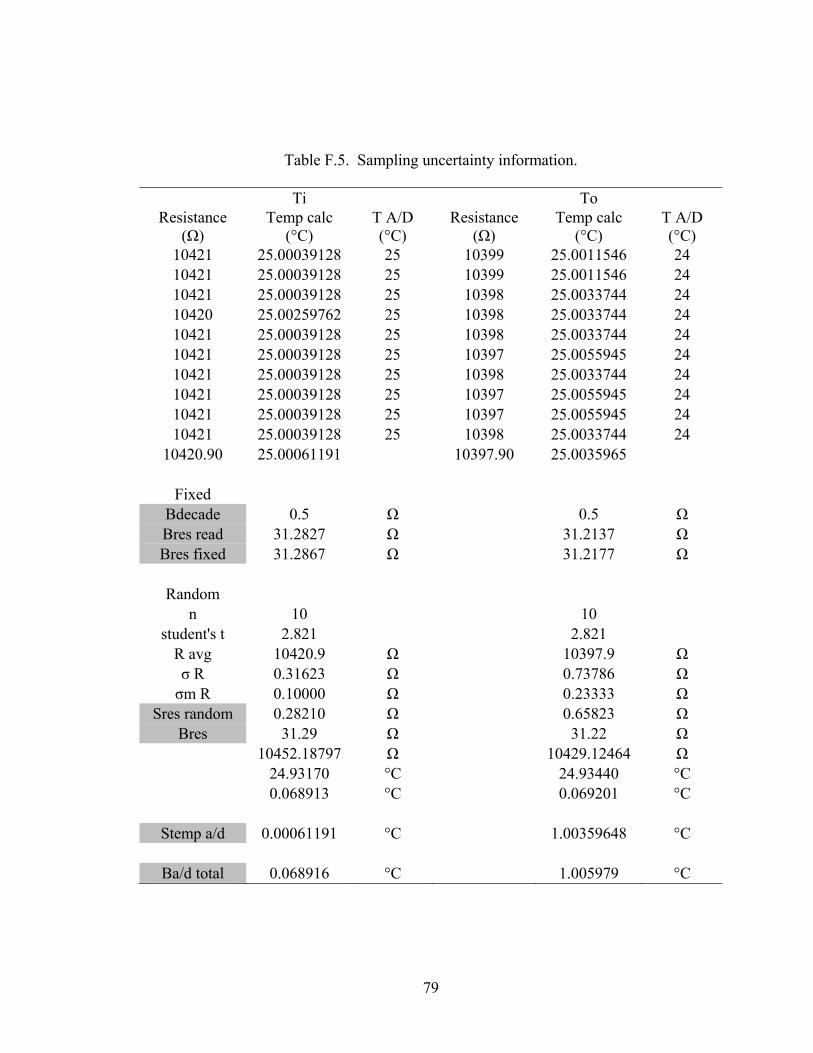
79
Table F.5. Sampling uncertainty information.
Ti To Resistance
(Ω) Temp calc
(°C) T A/D (°C)
Resistance (Ω)
Temp calc (°C)
T A/D (°C)
10421 25.00039128 25 10399 25.0011546 24 10421 25.00039128 25 10399 25.0011546 24 10421 25.00039128 25 10398 25.0033744 24 10420 25.00259762 25 10398 25.0033744 24 10421 25.00039128 25 10398 25.0033744 24 10421 25.00039128 25 10397 25.0055945 24 10421 25.00039128 25 10398 25.0033744 24 10421 25.00039128 25 10397 25.0055945 24 10421 25.00039128 25 10397 25.0055945 24 10421 25.00039128 25 10398 25.0033744 24
10420.90 25.00061191 10397.90 25.0035965
Fixed Bdecade 0.5 Ω 0.5 Ω Bres read 31.2827 Ω 31.2137 Ω Bres fixed 31.2867 Ω 31.2177 Ω
Random
n 10 10 student's t 2.821 2.821
R avg 10420.9 Ω 10397.9 Ω σ R 0.31623 Ω 0.73786 Ω σm R 0.10000 Ω 0.23333 Ω
Sres random 0.28210 Ω 0.65823 Ω Bres 31.29 Ω 31.22 Ω
10452.18797 Ω 10429.12464 Ω 24.93170 °C 24.93440 °C 0.068913 °C 0.069201 °C
Stemp a/d 0.00061191 °C 1.00359648 °C
Ba/d total 0.068916 °C 1.005979 °C
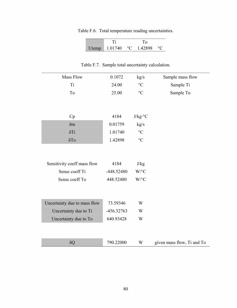
80
Table F.6. Total temperature reading uncertainties.
Ti To Utemp 1.01740 °C 1.42898 °C
Table F.7. Sample total uncertainty calculation.
Mass Flow 0.1072 kg/s Sample mass flow
Ti 24.00 °C Sample Ti
To 25.00 °C Sample To
Cp 4184 J/kg·°C
δm 0.01759 kg/s
δTi 1.01740 °C
δTo 1.42898 °C
Sensitivity coeff mass flow 4184 J/kg
Sense coeff Ti -448.52480 W/°C
Sense coeff To 448.52480 W/°C
Uncertainty due to mass flow 73.59346 W
Uncertainty due to Ti -456.32763 W
Uncertainty due to To 640.93428 W
δQ 790.22000 W given mass flow, Ti and To
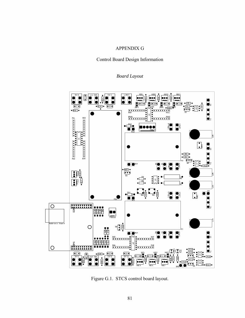
81
APPENDIX G
Control Board Design Information
Board Layout
Figure G.1. STCS control board layout.
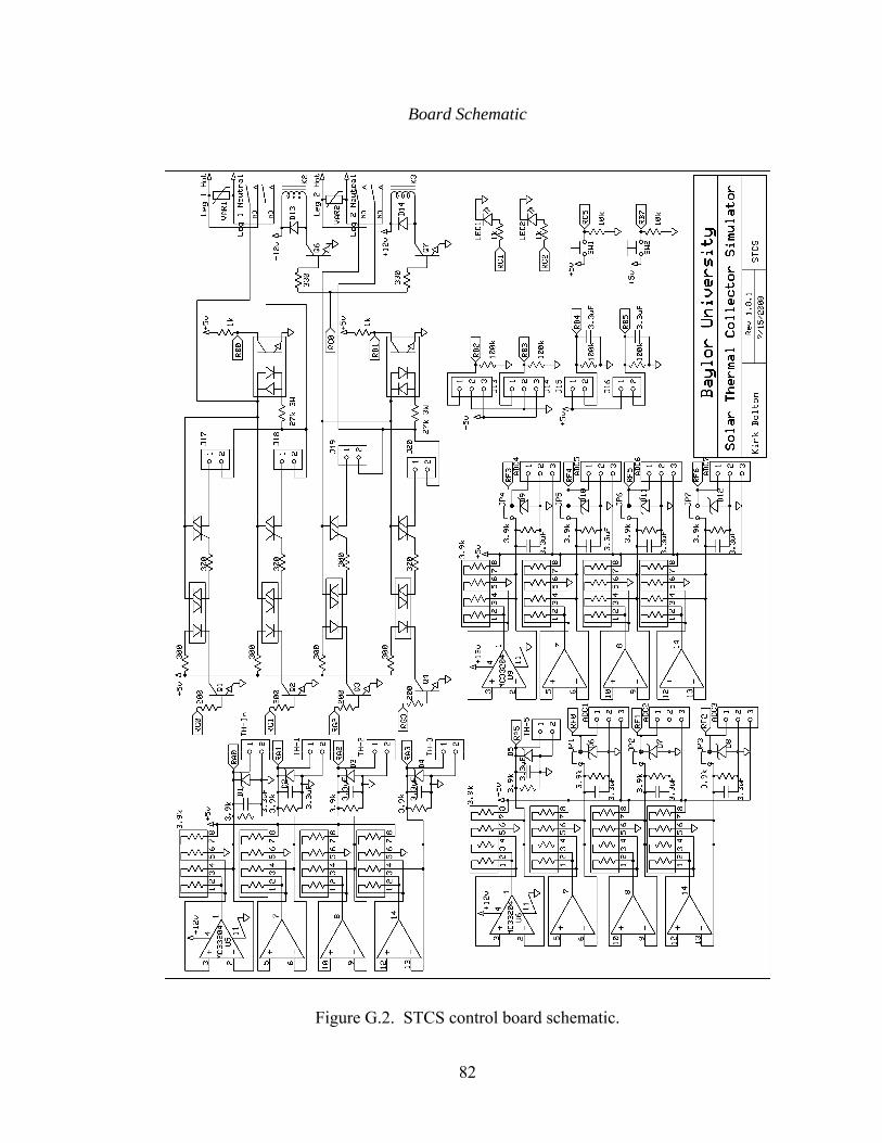
82
Board Schematic
Figure G.2. STCS control board schematic.
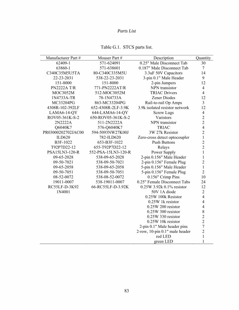
83
Parts List
Table G.1. STCS parts list.
Manufacturer Part # Mouser Part # Description Quantity 62409-1 571-624091 0.25" Male Disconnect Tab 30 63860-1 571-638601 0.187" Male Disconnect Tab 7
C340C35M5U5TA 80-C340C335M5U 3.3uF 50V Capacitors 14 22-23-2031 538-22-23-2031 3-pin 0.1" Male Header 9 151-8000 151-8000 2-pin Jumpers 12
PN2222A T/R 771-PN2222AT/R NPN transistor 4 MOC3052M 512-MOC3052M TRIAC Drivers 4 1N4733A-TR 78-1N4733A Zener Diodes 12 MC33204PG 863-MC33204PG Rail-to-rail Op Amps 3
4308R-102-392LF 652-4308R-2LF-3.9K 3.9k isolated resistor network 12 LAMA6-14-QY 644-LAMA6-14-QY Screw Lugs 4
ROV05-361K-S-2 650-ROV05-361K-S-2 Varistors 2 2N2222A 511-2N2222A NPN transistor 2 Q6040K7 576-Q6040K7 TRIAC 4
PR03000202702JAC00 594-5093NW27K00J 3W 27k Resistor 2 ILD620 782-ILD620 Zero-cross detect optocoupler 1
B3F-1022 653-B3F-1022 Push Buttons 2 T92P7D22-12 655-T92P7D22-12 Relays 2
PSA15LN3-120-R 552-PSA-15LN3-120-R Power Supply 1 09-65-2028 538-09-65-2028 2-pin 0.156" Male Header 1 09-50-7021 538-09-50-7021 2-pin 0.156" Female Plug 2 09-65-2058 538-09-65-2058 5-pin 0.156" Male Header 1 09-50-7051 538-09-50-7051 5-pin 0.156" Female Plug 2 08-52-0072 538-08-52-0072 0.156" Crimp Pins 10 19011-0007 538-19011-0007 0.25" Female Disconnect Tabs 24
RC55LF-D-3K92 66-RC55LF-D-3.92K 0.25W 3.92k 0.1% resistor 12 1N4001 50V 1A diode 2
0.25W 100k Resistor 4 0.25W 1k resistor 4 0.25W 200 resistor 4 0.25W 300 resistor 8 0.25W 330 resistor 2 0.25W 10k resistor 2 2-pin 0.1" Male header pins 7 2-row, 10-pin 0.1" male header 2 red LED 1 green LED 1

84
APPENDIX H
Source Code
Files Included in Project
The files that are included in the project are listed below. All these files, as well
as the project itself, are available from the Modtronix Engineering website located at
http://www.modtronix.com/product_info.php?cPath=1_36&products_id=149. The files
that were modified are shown in full later in this appendix.
SOURCE FILES appcfg.c arp.c arptsk.c cmd.c delay.c dhcp.c dns.c fsee.c ftp.c helpers.c http.c httpexec.c i2c.c icmp.c ip.c mac.c mxwebsrvr.c nbns.c sercfg.c serint.c stacktsk.c tcp.c tick.c udp.c xeeprom.c
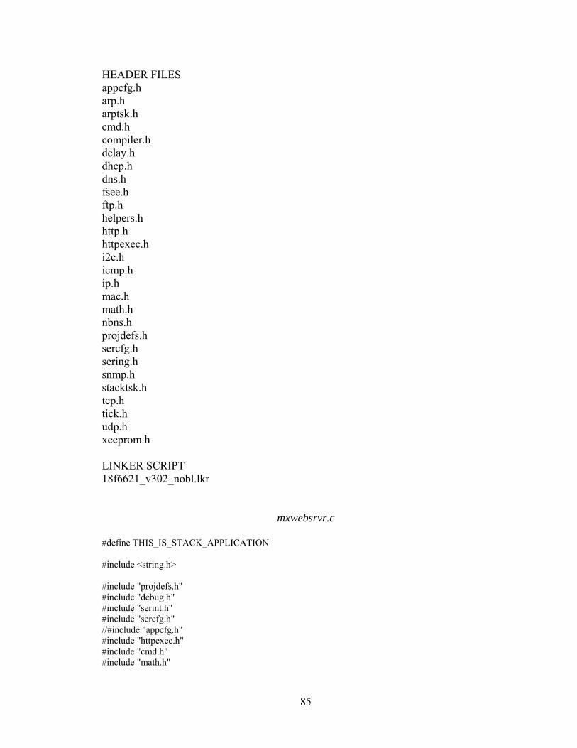
85
HEADER FILES appcfg.h arp.h arptsk.h cmd.h compiler.h delay.h dhcp.h dns.h fsee.h ftp.h helpers.h http.h httpexec.h i2c.h icmp.h ip.h mac.h math.h nbns.h projdefs.h sercfg.h sering.h snmp.h stacktsk.h tcp.h tick.h udp.h xeeprom.h LINKER SCRIPT 18f6621_v302_nobl.lkr
mxwebsrvr.c #define THIS_IS_STACK_APPLICATION #include <string.h> #include "projdefs.h" #include "debug.h" #include "serint.h" #include "sercfg.h" //#include "appcfg.h" #include "httpexec.h" #include "cmd.h" #include "math.h"
86
#include "net\cpuconf.h" #include "net\stacktsk.h" #include "net\fsee.h" #include "net\tick.h" #include "net\helpers.h" #include "net\delay.h" #include "net\udp.h" #include "net\xeeprom.h" #if defined(STACK_USE_DHCP) #include "net\dhcp.h" #endif #if defined(STACK_USE_HTTP_SERVER) #include "net\http.h" #endif #if defined(STACK_USE_FTP_SERVER) #include "net\ftp.h" #endif #if defined(STACK_USE_ANNOUNCE) #include "net\announce.h" #endif #if defined(STACK_USE_NBNS) #include "net\nbns.h" #endif ///////////////////////////////////////////////// //Debug defines #define debugPutMsg(msgCode) debugPut2Bytes(0xD6, msgCode) #define debugPutMsgRomStr(msgCode, strStr) debugMsgRomStr(0xD6, msgCode, msgStr) ///////////////////////////////////////////////// //Version number // - n = major part, and can be 1 or 2 digets long // - mm is minor part, and must be 2 digets long! ROM char APP_VER_STR[] = "V3.06"; BYTE myDHCPBindCount = 0; #if defined(STACK_USE_DHCP) extern BYTE DHCPBindCount; #else //If DHCP is not enabled, force DHCP update. #define DHCPBindCount 1 #endif //TODO Remove this later #if defined(APP_USE_ADC8) extern BYTE AdcValues[ADC_CHANNELS]; #elif defined(APP_USE_ADC10)
87
extern WORD AdcValues[ADC_CHANNELS]; #endif /* static union struct unsigned int bFreezeADCBuf : 1; //Stop updating AdcValues[] ADC buffer bits; BYTE Val; mainFlags; */ static void InitializeBoard(void); static void ProcessIO(void); static UDP_SOCKET udpSocketUserRx = INVALID_UDP_SOCKET; static UDP_SOCKET udpSocketUserTx = INVALID_UDP_SOCKET; static NODE_INFO udpServerNode2; static void myUDPInit(void); static void myUDPProc(void); static void myTempSens(void); static void mySafeProc(void); #pragma udata MyVars_one unsigned char k; unsigned char j; signed int tempsens1, tempsens2, tempsens3, tempsens4, tempsens5; unsigned short int adcval6, adcval7, adcval8, adcval9, adcval10, adcval11, adcval12; unsigned int timerhigh, timerlow, timertemp1, timertemp2, timerval; unsigned int flowtick1, flowtick2; unsigned int delayval, delayval2, delayval3; BOOL E1on, E2on, E3on, E4on; unsigned char myerror; unsigned char udpBufSize; unsigned long int button_ctr, i; unsigned short int sumadc1, sumadc2, sumadc3, sumadc4, sumadc5, sumadc6, sumadc7, sumadc8, sumadc9, sumadc10, sumadc11, sumadc12; signed float mathtemp; BOOL flowstate1, flowstate2; #pragma udata MyVars_two BYTE udpRxBuf[11]; BYTE udpTxBuf[72]; BYTE udpBytesReceived; BYTE adcread1[10]; BYTE adcread2[10]; BYTE adcread3[10]; BYTE adcread4[10]; BYTE adcread5[10]; BYTE adcread6[10]; BYTE adcread7[10];
88
BYTE adcread8[10]; BYTE adcread9[10]; BYTE adcread10[10]; BYTE adcread11[10]; BYTE adcread12[10]; #pragma udata ///////////////////////////////////////////////// //High Interrupt ISR #if defined(MCHP_C18) #pragma interrupt HighISR save=section(".tmpdata") void HighISR(void) #elif defined(HITECH_C18) #if defined(STACK_USE_SLIP) extern void MACISR(void); #endif void interrupt HighISR(void) #endif //TMR0 is used for the ticks if (INTCON_TMR0IF) TickUpdate(); #if defined(STACK_USE_SLIP) MACISR(); #endif INTCON_TMR0IF = 0; //INT0 zero-cross detection interrupt that sets the delay value of TMR1 if (INTCON_INT0IF) timerval = timertemp2 - delayval; timerhigh = (timerval>>8); timerlow = timerval - (timerhigh<<8); TMR1H = timerhigh; TMR1L = timerlow; INTCON_INT0IF = 0; T1CON_TMR1ON = 1; //INT1 zero-cross detection tinterrupt that sets the delay value of TMR3 if (INTCON3_INT1IF) timerval = timertemp2 - delayval; timerhigh = (timerval>>8); timerlow = timerval - (timerhigh<<8); TMR3H = timerhigh; TMR3L = timerlow; INTCON3_INT1IF = 0; T3CON_TMR3ON = 1;
89
//TMR1 interrupt that controls the 1st and 2nd triacs if (PIR1_TMR1IF) T1CON_TMR1ON = 0; if(myerror == 0) if(E1on) PORTG_RG0 = 1; if(E2on) PORTG_RG1 = 1; i = 6; while (i != 0)
i--; PORTG_RG0 = PORTG_RG1 = 0; PIR1_TMR1IF = 0; //TMR3 interrupt that controls the 3rd and 4th triacs if (PIR2_TMR3IF) T3CON_TMR3ON = 0; if(myerror == 0) if(E3on) PORTG_RG2 = 1; if(E4on) PORTG_RG3 = 1; i = 6; while (i != 0)
i--; PORTG_RG2 = PORTG_RG3 = 0; PIR2_TMR3IF = 0; /* //INT2 is used to detect the rising edge of an external flow meter if (INTCON3_INT2IF) flowtick1 += 1; INTCON3_INT2IF = 0; //INT3 is used to detect the rising edge of an external flow meter if (INTCON3_INT3IF) flowtick2 += 1; INTCON3_INT3IF = 0; */ #ifdef SER_USE_INTERRUPT //USART Receive if(PIR1_RCIF && PIE1_RCIE) serRxIsr();
90
//USART Transmit if(PIR1_TXIF && PIE1_TXIE) serTxIsr(); #endif #if defined(MCHP_C18) #pragma code highVector=HIVECTOR_ADR void HighVector (void) _asm goto HighISR _endasm #pragma code /* return to default code section */ #endif /* * Fast User process. Place all high priority code that has to be called often * in this function. * * !!!!! IMPORTANT !!!!! * This function is called often, and should be very fast! */ void fastUserProcess(void) CLRWDT(); /* * Main entry point. */ void main(void) static TICK8 t = 0; static TICK8 tmr10ms = 0; //Initialize any application specific hardware. InitializeBoard(); //Initialize all stack related components. Following steps must //be performed for all applications using PICmicro TCP/IP Stack. TickInit(); //Initialize file system. fsysInit(); //Intialize HTTP Execution unit htpexecInit();
91
//Initialze serial port serInit(); //Initialize Stack and application related NV variables. appcfgInit(); appcfgUSART(); //Configure the USART #ifdef SER_USE_INTERRUPT //Interrupt enabled serial ports have to be enabled serEnable(); #endif //appcfgCpuIO(); //Configure the CPU's I/O port pin directions - input or output appcfgCpuIOValues(); //Configure the CPU's I/O port pin default values appcfgADC(); //Configure ADC unit //appcfgPWM(); //Configure PWM Channels //Serial configuration menu - display it for configured time and allow user to enter configuration menu scfInit(appcfgGetc(APPCFG_STARTUP_SER_DLY)); StackInit(); #if defined(STACK_USE_HTTP_SERVER) HTTPInit(); #endif /* #if defined(STACK_USE_FTP_SERVER) FTPInit(); #endif */ //Initializes "UDP Command Port" and "UDP Command Responce Port". //cmdUdpInit(); #if defined(STACK_USE_DHCP) || defined(STACK_USE_IP_GLEANING) DHCPReset(); //Initialize DHCP module //If DHCP is NOT enabled if ((appcfgGetc(APPCFG_NETFLAGS) & APPCFG_NETFLAGS_DHCP) == 0) //Force IP address display update. myDHCPBindCount = 1; #if defined(STACK_USE_DHCP) DHCPDisable(); #endif #endif #if (DEBUG_MAIN >= LOG_DEBUG) debugPutMsg(1); //@mxd:1:Starting main loop #endif myUDPInit(); myTempSens(); /* * Once all items are initialized, go into infinite loop and let * stack items execute their tasks.
92
* If application needs to perform its own task, it should be * done at the end of while loop. * Note that this is a "co-operative mult-tasking" mechanism * where every task performs its tasks (whether all in one shot * or part of it) and returns so that other tasks can do their * job. * If a task needs very long time to do its job, it must broken * down into smaller pieces so that other tasks can have CPU time. */ while(1) //Clear timer 1 every cycle, can be used to measure events. Has a overflow of 65ms. //Get delay in this function with: // TMR1L | (TMR1H<<8) //TMR1H = 0; //First write to TMR1H buffer! //TMR1L = 0; //This write will also update TMR1H with value written above to buffer //Blink SYSTEM LED every second. if (appcfgGetc(APPCFG_SYSFLAGS) & APPCFG_SYSFLAGS_BLINKB6) if ( TickGetDiff8bit(t) >= ((TICK8)TICKS_PER_SECOND / (TICK8)2) ) t = TickGet8bit(); TRISB_RB6 = 0; LATB6 ^= 1; //Enter each 10ms if ( TickGetDiff8bit(tmr10ms) >= ((TICK8)TICKS_PER_SECOND / (TICK8)100) ) tmr10ms = TickGet8bit(); //This task performs normal stack task including checking for incoming packet, //type of packet and calling appropriate stack entity to process it. StackTask(); //Process "UDP Command Port" and "UDP Command Responce Port" //cmdProcess(); #if defined(STACK_USE_HTTP_SERVER) //This is a TCP application. It listens to TCP port 80 //with one or more sockets and responds to remote requests. HTTPServer(); #endif /* #if defined(STACK_USE_FTP_SERVER) FTPServer(); #endif */ #if defined(STACK_USE_ANNOUNCE) DiscoveryTask();
93
#endif #if defined(STACK_USE_NBNS) NBNSTask(); #endif //Add your application speicifc tasks here. ProcessIO(); ////////////////////////////////////////////////////////////////////////////////////// //Start of Kirk's thesis code myTempSens(); //Task to read temperature sensors myUDPProc(); //Task to send and recieve UDP communications mySafeProc(); //INT2 is used to detect the rising edge of an external flow meter if (PORTB_RB2 == 1) if(!flowstate1) flowtick1 += 1; flowstate1 = 1; else if(PORTB_RB2 == 0) flowstate1 &= 0; //INT3 is used to detect the rising edge of an external flow meter if (PORTB_RB3 == 1) if(!flowstate2) flowtick2 += 1; flowstate2 = 1; else if(PORTB_RB3 == 0) flowstate2 &= 0; while((PORTC_RC5 == 1)||(PORTB_RB7 == 1)) button_ctr++; if(button_ctr >= 500000) if((PORTC_RC5 == 1)&&(PORTB_RB7 == 0)) i = 500; while (i != 0) i--;
94
delayval++; else if((PORTC_RC5 == 0)&&(PORTB_RB7 == 1)) i = 500; while (i != 0) i--; delayval--; else if((PORTC_RC5 == 1)&&(PORTB_RB7 == 1)) XEEBeginRead(EEPROM_CONTROL, 0xFFF0); delayval2 = XEERead(); delayval3 = XEERead(); XEEEndRead(); delayval3 = ((delayval2<<8) + delayval3); if(delayval != delayval3) delayval2 = delayval>>8; delayval3 = delayval - (delayval2<<8); XEEBeginWrite(EEPROM_CONTROL, 0xFFF0); XEEWrite(delayval2); XEEWrite(delayval3); XEEEndWrite(); button_ctr = 0; PORTC_RC1 = 1; PORTC_RC2 = 1; i = 500000; while (i != 0) i--; if(i%4000 == 0) CLRWDT(); PORTC_RC1 = 0; PORTC_RC2 = 0; CLRWDT(); button_ctr = 0; ///////////////////////////////////////////////////////////////////////////////////// //For DHCP information, display how many times we have renewed the IP //configuration since last reset. if ( DHCPBindCount != myDHCPBindCount ) #if (DEBUG_MAIN >= LOG_INFO)
95
debugPutMsg(2); //@mxd:2:DHCP Bind Count = %D debugPutByteHex(DHCPBindCount); #endif //Display new IP address #if (DEBUG_MAIN >= LOG_INFO) debugPutMsg(3); //@mxd:3:DHCP complete, IP = %D.%D.%D.%D debugPutByteHex(AppConfig.MyIPAddr.v[0]); debugPutByteHex(AppConfig.MyIPAddr.v[1]); debugPutByteHex(AppConfig.MyIPAddr.v[2]); debugPutByteHex(AppConfig.MyIPAddr.v[3]); #endif myDHCPBindCount = DHCPBindCount; #if defined(STACK_USE_ANNOUNCE) AnnounceIP(); #endif static void ProcessIO(void) //Convert next ADC channel, and store result in adcChannel array #if (defined(APP_USE_ADC8) || defined(APP_USE_ADC10)) && (ADC_CHANNELS > 0) static BYTE adcChannel; //Current ADC channel. Value from 0 - n //We are allowed to update AdcValues[] buffer //if (!mainFlags.bits.bFreezeADCBuf) //Increment to next ADC channel if ((++adcChannel) >= ADC_CHANNELS) adcChannel = 0; //Check if current ADC channel (adcChannel) is configured to be ADC channel if (adcChannel < ((~ADCON1) & 0x0F)) //Convert next ADC Channel ADCON0 &= ~0x3C; ADCON0 |= (adcChannel << 2); ADCON0_ADON = 1; //Switch on ADC ADCON0_GO = 1; //Go while (ADCON0_GO) FAST_USER_PROCESS(); //Wait for conversion to finish #if defined(APP_USE_ADC8) AdcValues[adcChannel] = ADRESH; #elif defined(APP_USE_ADC10) AdcValues[adcChannel] = ((WORD)ADRESH << 8) || ADRESL; #endif //Not ADC channel, set to 0
96
else AdcValues[adcChannel] = 0; #endif static ROM char HTTPHDR_AUTHORIZATION[] = "AUTHORIZATION: BASIC "; /** * This function is a "callback" from HTTPServer task. For each HTTP Header found in the HTTP Request * message from the client, this function is called. The application has the chance to parse the * received headers. * * @param httpInfo HTTP_INFO structure of current HTTP connection * @param hdr Buffer containing NULL terminated header to handle * @param rqstRes Name of the Requested resource - GET command's action. All characters are in uppercase! */ void HTTPProcessHdr(HTTP_INFO* httpInfo, BYTE* hdr, BYTE* rqstRes) BYTE i; char unpw[20]; //Buffer for storing username and password, seperated by ':' char base64[25]; //Buffer for storing base64 result //Check if buffer begins with ROM string, ignore case if (strBeginsWithIC((char*)hdr, HTTPHDR_AUTHORIZATION)) i = strcpyee2ram(unpw, APPCFG_USERNAME0, 8); //Returns number of bytes written, excluding terminating null unpw[i++] = ':'; //Overwrite terminating null with ':' strcpyee2ram(&unpw[i], APPCFG_PASSWORD0, 8); base64Encode((char*)base64, (char*)unpw, strlen(unpw)); if (strcmp( (char*)(&hdr[sizeof(HTTPHDR_AUTHORIZATION)-1]), base64) == 0) httpInfo->flags.bits.bUserLoggedIn = TRUE; #if (DEBUG_MAIN >= LOG_DEBUG) debugPutMsg(6); //@mxd:6:HTTP User Authenticated #endif ///////////////////////////////////////////////// //Implement callback for FTPVerify() function #if defined(STACK_USE_FTP_SERVER) #if (FTP_USER_NAME_LEN > APPCFG_USERNAME_LEN) #error "The FTP Username length can not be shorter then the APPCFG Username length!" #endif BOOL FTPVerify(char *login, char *password) #if (DEBUG_MAIN >= LOG_INFO)
97
debugPutMsg(4); //@mxd:4:Received FTP Login (%s) and Password (%s) debugPutString(login); debugPutString(password); #endif if (strcmpee2ram(login, APPCFG_USERNAME0) == 0) if (strcmpee2ram(password, APPCFG_PASSWORD0) == 0) return TRUE; return FALSE; #endif /** * Initialize the boards hardware */ static void InitializeBoard(void) #if (defined(MCHP_C18) && (defined(__18F458) || defined(__18F448) || defined(__18F6680))) \ || (defined(HITECH_C18) && (defined(_18F458) || defined(_18F448) || defined(_18F6680))) CMCON = 0x07; /* Comparators off CM2:CM0 = 111 for PIC 18F448, 18F458, 18F6680 */ #endif ///////////////////////////////////////////////// //Enable 4 x PLL if configuration bits are set to do so #if ( defined(MCHP_C18) && defined(__18F6621)) OSCCON = 0x04; //Enable PLL (PLLEN = 1) while (OSCCON_LOCK == 0); //Wait until PLL is stable (LOCK = 1) //Seeing that this code does currently not work with Hi-Tech compiler, disable this feature OSCCON_SCS1 = 1; //Switch on software 4 x PLL if flag is set in configuration data //if (appcfgGetc(APPCFG_SYSFLAGS) & APPCFG_SYSFLAGS_PLLON) // OSCCON_SCS1 = 1; // #endif ///////////////////////////////////////////////// //Setup timer1 as a free running 16 bit timer. Is incremented every 100ns. //Is used to measure events in code //1xxx xxxx = Enable read/write as a 16bit times. TMR1H is a buffer that is loaded when TMR1L is accessed. //xx00 xxxx = No prescaler //xxxx 0xxx = Timer1 oscillator disabled (RC0 and RC1) //xxxx xx0x = Internal clock source = Fosc/4 = 40/4 = 10MHz for a 40MHz clock //xxxx xxx1 = Timer 1 on //T1CON = 0x81; //Disable external pull-ups INTCON2_RBPU = 1;
98
//Enable interrupts T0CON = 0; INTCON_GIEH = 1; INTCON_GIEL = 1; ///////////////////////////////////////////////////// //Kirk's changes INTCON_INT0IE = 1; INTCON2_INTEDG0 = 1; INTCON2_INTEDG1 = 1; INTCON2_INTEDG2 = 1; // INT2 Edge Select(1=rising,0=falling) INTCON2_INTEDG3 = 1; // INT3 Edge Select(1=rising,0=falling) INTCON2_INT3IP = 1; INTCON3_INT1IP = 1; INTCON3_INT2IP = 1; INTCON3_INT1IE = 1; INTCON3_INT2IE = 0; // INT2 Enable INTCON3_INT3IE = 0; // INT3 Enable PIE1_TMR1IE = 1; PIE2_TMR3IE = 1; IPR1_TMR1IP = 1; IPR2_TMR3IP = 1; RCON_IPEN = 1; T1CON = 0b10010000; T3CON = 0b10010000; //changed from appcfg.c (commented out there) TRISA_RA0 = 1; TRISA_RA1 = 1; TRISA_RA2 = 1; TRISA_RA3 = 1; TRISA_RA5 = 1; TRISB_RB0 = 1; TRISB_RB1 = 1; TRISB_RB2 = 1; TRISB_RB3 = 1; TRISB_RB4 = 1; TRISB_RB5 = 1; TRISB_RB7 = 1; TRISC_RC0 = 0; TRISC_RC1 = 0; TRISC_RC2 = 0; TRISC_RC5 = 1; TRISF = 0xFF; TRISG_RG0 = 0; TRISG_RG1 = 0; TRISG_RG2 = 0; TRISG_RG3 = 0; WDTCON = 0b00000001;
99
static void myUDPInit(void) timerhigh = timerlow = 255; flowtick1 = flowtick2 = 0; timerval = 65535; button_ctr = 0; XEEBeginRead(EEPROM_CONTROL, 0xFFF0); delayval2 = XEERead(); delayval3 = XEERead(); XEEEndRead(); delayval = (delayval2<<8) + delayval3; E1on = E2on = E3on = E4on = 0; myerror = 0; udpBufSize = 0; udpServerNode2.MACAddr.v[0] = 0; udpServerNode2.MACAddr.v[1] = 0; udpServerNode2.MACAddr.v[2] = 0; udpServerNode2.MACAddr.v[3] = 0; udpServerNode2.MACAddr.v[4] = 0; udpServerNode2.MACAddr.v[5] = 0; udpServerNode2.IPAddr.Val = 0x6900A8C0L; //108.0.168.192 entered in reverse order udpSocketUserRx = UDPOpen(4000, &udpServerNode2, INVALID_UDP_PORT); for(j=0;j<11;j++) udpRxBuf[j] = 0; for(j=0;j<72;j++) udpTxBuf[j] = 0; k=0; static void myUDPProc(void) if (UDPIsGetReady(udpSocketUserRx)) udpBytesReceived = UDPGetArray(udpRxBuf, 11); UDPDiscard(); if((udpRxBuf[0] == 80)&&(udpRxBuf[6] == 69)) //80 = 'P', 69 = 'E' if(((udpRxBuf[1]>=48)&&(udpRxBuf[1]<=57))&&((udpRxBuf[2]>=48)&&(udpRxBuf[2]<=57))&&((udpRxBuf[3]>=48)&&(udpRxBuf[3]<=57))&&((udpRxBuf[4]>=48)&&(udpRxBuf[4]<=57))&&((udpRxBuf[5]>=48)&&(udpRxBuf[5]<=57))) //timertemp1=((udpRxBuf[1]-48)*10000)+((udpRxBuf[2]-48)*1000)+((udpRxBuf[3]-48)*100)+((udpRxBuf[4]-48)*10)+(udpRxBuf[5]-48); timertemp1=((udpRxBuf[1]-48)*10000)+((udpRxBuf[2]-48)*1000)+((udpRxBuf[4]-48)*10)+(udpRxBuf[5]-48); timertemp2=(udpRxBuf[3]-48); timertemp2 *= 100; timertemp1 += timertemp2; if(timertemp1<=37266) timertemp2 = 65535 - timertemp1;
100
else timertemp2 = 65535; udpRxBuf[7] = udpRxBuf[8] = udpRxBuf[9] = udpRxBuf[10] = 48; else //turn off all triacs timertemp2 = 65535; udpRxBuf[7] = udpRxBuf[8] = udpRxBuf[9] = udpRxBuf[10] = 48; if(udpRxBuf[7] == 49) E1on = 1; else E1on = 0; if(udpRxBuf[8] == 49) E2on = 1; else E2on = 0; if(udpRxBuf[9] == 49) E3on = 1; else E3on = 0; if(udpRxBuf[10] == 49) E4on = 1; else E4on = 0; else if(udpRxBuf[0] == 82) //82 = 'R' if (udpSocketUserTx == INVALID_UDP_SOCKET) udpSocketUserTx = UDPOpen((WORD)4001, UDPGetNodeInfo(), (WORD)4001); if (myerror == 0) udpTxBuf[0]=udpTxBuf[5]=udpTxBuf[10]=udpTxBuf[15]=udpTxBuf[20]=udpTxBuf[25]=udpTxBuf[30]=udpTxBuf[35]=udpTxBuf[40]=udpTxBuf[45]=udpTxBuf[50]=udpTxBuf[55]=65; udpTxBuf[60] = udpTxBuf[66] = 81; //81 = 'Q' if(tempsens1<0) udpTxBuf[1] = 45; //45 = '-' tempsens1 = tempsens1 * -1; else udpTxBuf[1]=((tempsens1-(tempsens1%1000))/1000)+48; udpTxBuf[2]=(((tempsens1%1000)-(tempsens1%100))/100)+48; udpTxBuf[3]=(((tempsens1%100)-(tempsens1%10))/10)+48; udpTxBuf[4]=(tempsens1%10)+48; if(tempsens2<0) udpTxBuf[6] = 45; tempsens2 = tempsens2 * -1; else udpTxBuf[6]=((tempsens2-(tempsens2%1000))/1000)+48; udpTxBuf[7]=(((tempsens2%1000)-(tempsens2%100))/100)+48; udpTxBuf[8]=(((tempsens2%100)-(tempsens2%10))/10)+48; udpTxBuf[9]=(tempsens2%10)+48;
101
if(tempsens3<0) udpTxBuf[11] = 45; tempsens3 = tempsens3 * -1; else udpTxBuf[11]=((tempsens3-(tempsens3%1000))/1000)+48; udpTxBuf[12]=(((tempsens3%1000)-(tempsens3%100))/100)+48; udpTxBuf[13]=(((tempsens3%100)-(tempsens3%10))/10)+48; udpTxBuf[14]=(tempsens3%10)+48; if(tempsens4<0) udpTxBuf[16] = 45; tempsens4 = tempsens4 * -1; else udpTxBuf[16]=((tempsens4-(tempsens4%1000))/1000)+48; udpTxBuf[17]=(((tempsens4%1000)-(tempsens4%100))/100)+48; udpTxBuf[18]=(((tempsens4%100)-(tempsens4%10))/10)+48; udpTxBuf[19]=(tempsens4%10)+48; if(tempsens5<0) udpTxBuf[21] = 45; tempsens5 = tempsens5 * -1; else udpTxBuf[21]=((tempsens5-(tempsens5%1000))/1000)+48; udpTxBuf[22]=(((tempsens5%1000)-(tempsens5%100))/100)+48; udpTxBuf[23]=(((tempsens5%100)-(tempsens5%10))/10)+48; udpTxBuf[24]=(tempsens5%10)+48; if(adcval6<0) udpTxBuf[26] = 45; adcval6 = adcval6 * -1; else udpTxBuf[26]=((adcval6-(adcval6%1000))/1000)+48; udpTxBuf[27]=(((adcval6%1000)-(adcval6%100))/100)+48; udpTxBuf[28]=(((adcval6%100)-(adcval6%10))/10)+48; udpTxBuf[29]=(adcval6%10)+48; if(adcval7<0) udpTxBuf[31] = 45; adcval7 = adcval7 * -1; else udpTxBuf[31]=((adcval7-(adcval7%1000))/1000)+48; udpTxBuf[32]=(((adcval7%1000)-(adcval7%100))/100)+48; udpTxBuf[33]=(((adcval7%100)-(adcval7%10))/10)+48; udpTxBuf[34]=(adcval7%10)+48; if(adcval8<0) udpTxBuf[36] = 45; adcval8 = adcval8 * -1; else udpTxBuf[36]=((adcval8-(adcval8%1000))/1000)+48;
102
udpTxBuf[37]=(((adcval8%1000)-(adcval8%100))/100)+48; udpTxBuf[38]=(((adcval8%100)-(adcval8%10))/10)+48; udpTxBuf[39]=(adcval8%10)+48; if(adcval9<0) udpTxBuf[41] = 45; adcval9 = adcval9 * -1; else udpTxBuf[41]=((adcval9-(adcval9%1000))/1000)+48; udpTxBuf[42]=(((adcval9%1000)-(adcval9%100))/100)+48; udpTxBuf[43]=(((adcval9%100)-(adcval9%10))/10)+48; udpTxBuf[44]=(adcval9%10)+48; if(adcval10<0) udpTxBuf[46] = 45; adcval10 = adcval10 * -1; else udpTxBuf[46]=((adcval10-(adcval10%1000))/1000)+48; udpTxBuf[47]=(((adcval10%1000)-(adcval10%100))/100)+48; udpTxBuf[48]=(((adcval10%100)-(adcval10%10))/10)+48; udpTxBuf[49]=(adcval10%10)+48; if(adcval11<0) udpTxBuf[51] = 45; adcval11 = adcval11 * -1; else udpTxBuf[51]=((adcval11-(adcval11%1000))/1000)+48; udpTxBuf[52]=(((adcval11%1000)-(adcval11%100))/100)+48; udpTxBuf[53]=(((adcval11%100)-(adcval11%10))/10)+48; udpTxBuf[54]=(adcval11%10)+48; if(adcval12<0) udpTxBuf[56] = 45; adcval12 = adcval12 * -1; else udpTxBuf[56]=((adcval12-(adcval12%1000))/1000)+48; udpTxBuf[57]=(((adcval12%1000)-(adcval12%100))/100)+48; udpTxBuf[58]=(((adcval12%100)-(adcval12%10))/10)+48; udpTxBuf[59]=(adcval12%10)+48; udpTxBuf[61]=((flowtick1-(flowtick1%10000))/10000)+48; udpTxBuf[62]=(((flowtick1%10000)-(flowtick1%1000))/1000)+48; udpTxBuf[63]=(((flowtick1%1000)-(flowtick1%100))/100)+48; udpTxBuf[64]=(((flowtick1%100)-(flowtick1%10))/10)+48; udpTxBuf[65]=(flowtick1%10)+48; udpTxBuf[67]=((flowtick2-(flowtick2%10000))/10000)+48; udpTxBuf[68]=(((flowtick2%10000)-(flowtick2%1000))/1000)+48; udpTxBuf[69]=(((flowtick2%1000)-(flowtick2%100))/100)+48; udpTxBuf[70]=(((flowtick2%100)-(flowtick2%10))/10)+48; udpTxBuf[71]=(flowtick2%10)+48; udpBufSize = 72;
103
else if (myerror != 0) udpTxBuf[0] = 69; //69 = 'E' switch(myerror) case 0: udpTxBuf[1] = 0; udpTxBuf[2] = 0; udpTxBuf[3] = 0; break; case 1: udpTxBuf[1] = 79; //79 = 'O' udpTxBuf[2] = 84; //84 = 'T' udpTxBuf[3] = 49; //49 = '1' break; case 2: udpTxBuf[1] = 79; udpTxBuf[2] = 84; udpTxBuf[3] = 50; //50 = '2' break; case 3: udpTxBuf[1] = 79; udpTxBuf[2] = 84; udpTxBuf[3] = 51; //51 = '3' break; case 4: udpTxBuf[1] = 79; udpTxBuf[2] = 84; udpTxBuf[3] = 52; //52 = '4' break; case 5: udpTxBuf[1] = 79; udpTxBuf[2] = 84; udpTxBuf[3] = 53; //53 = '5' break; case 6: udpTxBuf[1] = 78; //78 = 'N' udpTxBuf[2] = 70; //70 = 'F' udpTxBuf[3] = 67; //67 = 'C' break; case 7: udpTxBuf[1] = 76; //76 = 'L' udpTxBuf[2] = udpTxBuf[3] = 68; //68 = 'D' break; default: udpTxBuf[1] = 0; udpTxBuf[2] = 0; udpTxBuf[3] = 0; break; udpBufSize = 4; if (UDPIsPutReady(udpSocketUserTx)) UDPPutArray(udpTxBuf, udpBufSize);
104
UDPFlush(); flowtick1 = flowtick2 = 0; udpBytesReceived = 0; udpRxBuf[0] = 0; static void myTempSens(void) adcread1[k] = AdcValues[0]; adcread2[k] = AdcValues[1]; adcread3[k] = AdcValues[2]; adcread4[k] = AdcValues[3]; adcread5[k] = AdcValues[4]; adcread6[k] = AdcValues[5]; adcread7[k] = AdcValues[6]; adcread8[k] = AdcValues[7]; adcread9[k] = AdcValues[8]; adcread10[k] = AdcValues[9]; adcread11[k] = AdcValues[10]; adcread12[k] = AdcValues[11]; if(k<9) k++; else k=0; sumadc1 = ((unsigned short int)adcread1[0]+adcread1[1]+adcread1[2]+adcread1[3]+adcread1[4]+adcread1[5]+adcread1[6]+adcread1[7]+adcread1[8]+adcread1[9]); sumadc2 = ((unsigned short int)adcread2[0]+adcread2[1]+adcread2[2]+adcread2[3]+adcread2[4]+adcread2[5]+adcread2[6]+adcread2[7]+adcread2[8]+adcread2[9]); sumadc3 = ((unsigned short int)adcread3[0]+adcread3[1]+adcread3[2]+adcread3[3]+adcread3[4]+adcread3[5]+adcread3[6]+adcread3[7]+adcread3[8]+adcread3[9]); sumadc4 = ((unsigned short int)adcread4[0]+adcread4[1]+adcread4[2]+adcread4[3]+adcread4[4]+adcread4[5]+adcread4[6]+adcread4[7]+adcread4[8]+adcread4[9]); sumadc5 = ((unsigned short int)adcread5[0]+adcread5[1]+adcread5[2]+adcread5[3]+adcread5[4]+adcread5[5]+adcread5[6]+adcread5[7]+adcread5[8]+adcread5[9]); sumadc6 = ((unsigned short int)adcread6[0]+adcread6[1]+adcread6[2]+adcread6[3]+adcread6[4]+adcread6[5]+adcread6[6]+adcread6[7]+adcread6[8]+adcread6[9]); sumadc7 = ((unsigned short int)adcread7[0]+adcread7[1]+adcread7[2]+adcread7[3]+adcread7[4]+adcread7[5]+adcread7[6]+adcread7[7]+adcread7[8]+adcread7[9]); sumadc8 = ((unsigned short int)adcread8[0]+adcread8[1]+adcread8[2]+adcread8[3]+adcread8[4]+adcread8[5]+adcread8[6]+adcread8[7]+adcread8[8]+adcread8[9]); sumadc9 = ((unsigned short int)adcread9[0]+adcread9[1]+adcread9[2]+adcread9[3]+adcread9[4]+adcread9[5]+adcread9[6]+adcread9[7]+adcread9[8]+adcread9[9]); sumadc10 = ((unsigned short int)adcread10[0]+adcread10[1]+adcread10[2]+adcread10[3]+adcread10[4]+adcread10[5]+adcread10[6]+adcread10[7]+adcread10[8]+adcread10[9]);
105
sumadc11 = ((unsigned short int)adcread11[0]+adcread11[1]+adcread11[2]+adcread11[3]+adcread11[4]+adcread11[5]+adcread11[6]+adcread11[7]+adcread11[8]+adcread11[9]); sumadc12 = ((unsigned short int)adcread12[0]+adcread12[1]+adcread12[2]+adcread12[3]+adcread12[4]+adcread12[5]+adcread12[6]+adcread12[7]+adcread12[8]+adcread12[9]); if(sumadc1<1730) mathtemp = -0.00000000000052329*pow((float)sumadc1,5.0); mathtemp += 0.00000000260072314*pow((float)sumadc1,4.0); mathtemp += -0.00000523178764528*pow((float)sumadc1,3.0); mathtemp += 0.005434431407362*pow((float)sumadc1,2.0); mathtemp += -3.42056952004796*(float)sumadc1; mathtemp += 1752.29254309834; tempsens1 = (signed short int)mathtemp; else mathtemp = -0.0000027311984329*pow((float)sumadc1,4.0); mathtemp += 0.0194388633179569*pow((float)sumadc1,3.0); mathtemp += -51.8906752847686*pow((float)sumadc1,2.0); mathtemp += 61571.2006129863*(float)sumadc1; mathtemp += -27398743.425479; tempsens1 = (signed short int)mathtemp; if(sumadc2<1690) mathtemp = -0.00000000000058244*pow((float)sumadc2,5.0); mathtemp += 0.00000000281568562*pow((float)sumadc2,4.0); mathtemp += -0.0000055156724076*pow((float)sumadc2,3.0); mathtemp += 0.00561707930690793*pow((float)sumadc2,2.0); mathtemp += -3.5006271502258*(float)sumadc2; mathtemp += 1765.26105212894; tempsens2 = (signed short int)mathtemp; else mathtemp = -0.000001786899713*pow((float)sumadc2,4.0); mathtemp += 0.0124091806685994*pow((float)sumadc2,3.0); mathtemp += -32.32293853072*pow((float)sumadc2,2.0); mathtemp += 37425.3414366233*(float)sumadc2; mathtemp += -16251527.2286374; tempsens2 = (signed short int)mathtemp; if(sumadc3<1690) mathtemp = -0.00000000000058244*pow((float)sumadc3,5.0); mathtemp += 0.00000000281568562*pow((float)sumadc3,4.0); mathtemp += -0.0000055156724076*pow((float)sumadc3,3.0); mathtemp += 0.00561707930690793*pow((float)sumadc3,2.0); mathtemp += -3.5006271502258*(float)sumadc3; mathtemp += 1765.26105212894; tempsens3 = (signed short int)mathtemp; else mathtemp = -0.000001786899713*pow((float)sumadc3,4.0); mathtemp += 0.0124091806685994*pow((float)sumadc3,3.0); mathtemp += -32.32293853072*pow((float)sumadc3,2.0); mathtemp += 37425.3414366233*(float)sumadc3; mathtemp += -16251527.2286374;
106
tempsens3 = (signed short int)mathtemp; if(sumadc4<1690) mathtemp = -0.00000000000058244*pow((float)sumadc4,5.0); mathtemp += 0.00000000281568562*pow((float)sumadc4,4.0); mathtemp += -0.0000055156724076*pow((float)sumadc4,3.0); mathtemp += 0.00561707930690793*pow((float)sumadc4,2.0); mathtemp += -3.5006271502258*(float)sumadc4; mathtemp += 1765.26105212894; tempsens4 = (signed short int)mathtemp; else mathtemp = -0.000001786899713*pow((float)sumadc4,4.0); mathtemp += 0.0124091806685994*pow((float)sumadc4,3.0); mathtemp += -32.32293853072*pow((float)sumadc4,2.0); mathtemp += 37425.3414366233*(float)sumadc4; mathtemp += -16251527.2286374; tempsens4 = (signed short int)mathtemp; if(sumadc5<1630) mathtemp = -0.00000000000070673*pow((float)sumadc5,5.0); mathtemp += 0.00000000317675615*pow((float)sumadc5,4.0); mathtemp += -0.00000579381911871*pow((float)sumadc5,3.0); mathtemp += 0.00553711614386062*pow((float)sumadc5,2.0); mathtemp += -3.32513525690608*(float)sumadc5; mathtemp += 1721.35016038486; tempsens5 = (signed short int)mathtemp; else mathtemp = -0.000270474861*pow((float)sumadc5,3.0); mathtemp += 1.34146153234*pow((float)sumadc5,2.0); mathtemp += -2219.54777573478*(float)sumadc5; mathtemp += 1225301.69715049; tempsens5 = (signed short int)mathtemp; adcval6 = sumadc6; adcval7 = sumadc7; adcval8 = sumadc8; adcval9 = sumadc9; adcval10 = sumadc10; adcval11 = sumadc11; adcval12 = sumadc12; static void mySafeProc(void) //checks if any of the temp sensors are above a max temp limit //set to 93.3 C if((tempsens1<933)&&(tempsens2<933)&&(tempsens3<933)&&(tempsens4<933)&&(tempsens5<933)&&(PORTB_RB4==1)&&(PORTB_RB5==0)) myerror = 0; else if(tempsens1>933) myerror = 1;
107
if(tempsens2>933) myerror = 2; if(tempsens3>933) myerror = 3; if(tempsens4>933) myerror = 4; if(tempsens5>933) myerror = 5; if(PORTB_RB4==0) myerror = 6; if(PORTB_RB5==1) myerror = 7; if (myerror == 0) PORTC_RC0 = 1; PORTC_RC1 = 1; PORTC_RC2 = 0; else if (myerror != 0) PORTC_RC0 = 0; PORTC_RC1 = 0; PORTC_RC2 = 1; E1on = E2on = E3on = E4on = 0;
compiler.h #ifndef COMPILER_H #define COMPILER_H #if defined(HI_TECH_C) #if defined(_MPC_) #define HITECH_C18 #else #error "Unknown part is selected." #endif #else #if !defined(_WIN32) #define MCHP_C18 #endif #endif #if defined(MCHP_C18) && defined(HITECH_C18) #error "Invalid Compiler selection." #endif #if !defined(MCHP_C18) && !defined(HITECH_C18) && !defined(_WIN32) #error "Compiler not supported." #endif #if defined(MCHP_C18) #include <p18cxxx.h> // p18cxxx.h must have current processor // defined. #include <stddef.h> //For offsetof macro #endif
108
#if defined(HITECH_C18) #include <pic18.h> #include <stdio.h> #include <stddef.h> //For offsetof macro #endif #if defined(__18CXX) //Microchip C18 compiler #define PERSISTENT #elif defined(HITECH_C18) //HiTech PICC18 Compiler #define PERSISTENT persistent #endif #include <stdlib.h> ///////////////////////////////////////////////// //Set some defines that are processor related #if defined(__18F452) || defined(_18F452) || defined(__18F458) || defined(_18F458) #define EEPROM_SIZE 256 #elif defined(__18F6621) || defined(_18F6621) \ || defined(__18F6527) || defined(_18F6527) \ || defined(__18F6627) || defined(_18F6627) \ || defined(__18F6680) || defined(_18F6680) #define EEPROM_SIZE 1024 #endif ///////////////////////////////////////////////// //Modify following macros depending on your interrupt usage #define ENABLE_INTERRUPTS() INTCON_GIEH = 1 #define DISBALE_INTERRUPTS() INTCON_GIEH = 0 ///////////////////////////////////////////////// //Data Types #undef BOOL #undef TRUE #undef FALSE #undef BYTE #undef WORD #undef DWORD typedef enum _BOOL FALSE = 0, TRUE BOOL; typedef unsigned char BYTE; // 8-bit typedef unsigned short int WORD; // 16-bit #ifndef _WIN32 typedef unsigned short long SWORD; // 24-bit #else typedef short int SWORD; #endif typedef unsigned long DWORD; // 32-bit typedef union _BYTE_VAL struct
109
unsigned int b0:1; unsigned int b1:1; unsigned int b2:1; unsigned int b3:1; unsigned int b4:1; unsigned int b5:1; unsigned int b6:1; unsigned int b7:1; bits; BYTE Val; BYTE_VAL; typedef union _SWORD_VAL SWORD Val; struct BYTE LSB; BYTE MSB; BYTE USB; byte; BYTE v[3]; SWORD_VAL; typedef struct _WORD_ARRAY BYTE offset0; BYTE offset1; WORD_ARRAY; #define WORD_LSB(a) ( (unsigned char) ((WORD_ARRAY)a).offset0 ) #define WORD_MSB(a) ( (unsigned char) ((WORD_ARRAY)a).offset1 ) typedef union _WORD_VAL WORD Val; struct BYTE LSB; BYTE MSB; byte; BYTE v[2]; WORD_VAL; #define LSB(a) ((a).v[0]) #define MSB(a) ((a).v[1]) typedef union _DWORD_VAL DWORD Val; struct BYTE LOLSB; BYTE LOMSB; BYTE HILSB; BYTE HIMSB;
110
byte; struct WORD LSW; WORD MSW; word; BYTE v[4]; DWORD_VAL; #define LOWER_LSB(a) ((a).v[0]) #define LOWER_MSB(a) ((a).v[1]) #define UPPER_LSB(a) ((a).v[2]) #define UPPER_MSB(a) ((a).v[3]) #define CLEAR_BIT(theByte, mask) (theByte &= (~mask)) #define SET_BIT(theByte, mask) (theByte |= mask) #define IS_BIT_SET(theByte, mask) (theByte & mask) #define IS_BIT_CLEAR(theByte, mask) ((theByte & mask) == 0) typedef BYTE BUFFER; #if defined(MCHP_C18) #define CLRWDT() ClrWdt() #define NOP() Nop() #define RESET() Reset() #define SLEEP() Sleep() #define ROM rom #define PORTA_RA0 PORTAbits.RA0 #define PORTA_RA1 PORTAbits.RA1 #define PORTA_RA2 PORTAbits.RA2 #define PORTA_RA3 PORTAbits.RA3 #define PORTA_RA4 PORTAbits.RA4 #define PORTA_RA5 PORTAbits.RA5 #define LATA0 LATAbits.LATA0 #define LATA1 LATAbits.LATA1 #define LATA2 LATAbits.LATA2 #define LATA3 LATAbits.LATA3 #define LATA4 LATAbits.LATA4 #define LATA5 LATAbits.LATA5 #define TRISA_RA0 TRISAbits.TRISA0 #define TRISA_RA1 TRISAbits.TRISA1 #define TRISA_RA2 TRISAbits.TRISA2 #define TRISA_RA3 TRISAbits.TRISA3 #define TRISA_RA4 TRISAbits.TRISA4 #define TRISA_RA5 TRISAbits.TRISA5 #define PORTB_RB0 PORTBbits.RB0 #define PORTB_RB1 PORTBbits.RB1 #define PORTB_RB2 PORTBbits.RB2 #define PORTB_RB3 PORTBbits.RB3 #define PORTB_RB4 PORTBbits.RB4 #define PORTB_RB5 PORTBbits.RB5 #define PORTB_RB6 PORTBbits.RB6 #define PORTB_RB7 PORTBbits.RB7 #define LATB0 LATBbits.LATB0
111
#define LATB1 LATBbits.LATB1 #define LATB2 LATBbits.LATB2 #define LATB3 LATBbits.LATB3 #define LATB4 LATBbits.LATB4 #define LATB5 LATBbits.LATB5 #define LATB6 LATBbits.LATB6 #define LATB7 LATBbits.LATB7 #define TRISB_RB0 TRISBbits.TRISB0 #define TRISB_RB1 TRISBbits.TRISB1 #define TRISB_RB2 TRISBbits.TRISB2 #define TRISB_RB3 TRISBbits.TRISB3 #define TRISB_RB4 TRISBbits.TRISB4 #define TRISB_RB5 TRISBbits.TRISB5 #define TRISB_RB6 TRISBbits.TRISB6 #define TRISB_RB7 TRISBbits.TRISB7 #define PORTC_RC0 PORTCbits.RC0 #define PORTC_RC1 PORTCbits.RC1 #define PORTC_RC2 PORTCbits.RC2 #define PORTC_RC3 PORTCbits.RC3 #define PORTC_RC4 PORTCbits.RC4 #define PORTC_RC5 PORTCbits.RC5 #define PORTC_RC6 PORTCbits.RC6 #define PORTC_RC7 PORTCbits.RC7 #define LATC0 LATCbits.LATC0 #define LATC1 LATCbits.LATC1 #define LATC2 LATCbits.LATC2 #define LATC3 LATCbits.LATC3 #define LATC4 LATCbits.LATC4 #define LATC5 LATCbits.LATC5 #define LATC6 LATCbits.LATC6 #define LATC7 LATCbits.LATC7 #define TRISC_RC0 TRISCbits.TRISC0 #define TRISC_RC1 TRISCbits.TRISC1 #define TRISC_RC2 TRISCbits.TRISC2 #define TRISC_RC3 TRISCbits.TRISC3 #define TRISC_RC4 TRISCbits.TRISC4 #define TRISC_RC5 TRISCbits.TRISC5 #define TRISC_RC6 TRISCbits.TRISC6 #define TRISC_RC7 TRISCbits.TRISC7 #define PORTD_RD0 PORTDbits.RD0 #define PORTD_RD1 PORTDbits.RD1 #define PORTD_RD2 PORTDbits.RD2 #define PORTD_RD3 PORTDbits.RD3 #define PORTD_RD4 PORTDbits.RD4 #define PORTD_RD5 PORTDbits.RD5 #define PORTD_RD6 PORTDbits.RD6 #define PORTD_RD7 PORTDbits.RD7 #define TRISD_RD0 TRISDbits.TRISD0 #define TRISD_RD1 TRISDbits.TRISD1 #define TRISD_RD2 TRISDbits.TRISD2 #define TRISD_RD3 TRISDbits.TRISD3 #define TRISD_RD4 TRISDbits.TRISD4 #define TRISD_RD5 TRISDbits.TRISD5 #define TRISD_RD6 TRISDbits.TRISD6
112
#define TRISD_RD7 TRISDbits.TRISD7 #define PORTE_RE0 PORTEbits.RE0 #define PORTE_RE1 PORTEbits.RE1 #define PORTE_RE2 PORTEbits.RE2 #define PORTE_RE3 PORTEbits.RE3 #define PORTE_RE4 PORTEbits.RE4 #define PORTE_RE5 PORTEbits.RE5 #define PORTE_RE6 PORTEbits.RE6 #define PORTE_RE7 PORTEbits.RE7 #define LATE0 LATEbits.LATE0 #define LATE1 LATEbits.LATE1 #define LATE2 LATEbits.LATE2 #define LATE3 LATEbits.LATE3 #define LATE4 LATEbits.LATE4 #define LATE5 LATEbits.LATE5 #define LATE6 LATEbits.LATE6 #define LATE7 LATEbits.LATE7 #define TRISE_RE0 TRISEbits.TRISE0 #define TRISE_RE1 TRISEbits.TRISE1 #define TRISE_RE2 TRISEbits.TRISE2 #define TRISE_RE3 TRISEbits.TRISE3 #define TRISE_RE4 TRISEbits.TRISE4 #define TRISE_RE5 TRISEbits.TRISE5 #define TRISE_RE6 TRISEbits.TRISE6 #define TRISE_RE7 TRISEbits.TRISE7 #define PORTF_RF0 PORTFbits.RF0 #define PORTF_RF1 PORTFbits.RF1 #define PORTF_RF2 PORTFbits.RF2 #define PORTF_RF3 PORTFbits.RF3 #define PORTF_RF4 PORTFbits.RF4 #define PORTF_RF5 PORTFbits.RF5 #define PORTF_RF6 PORTFbits.RF6 #define PORTF_RF7 PORTFbits.RF7 #define LATF0 LATFbits.LATF0 #define LATF1 LATFbits.LATF1 #define LATF2 LATFbits.LATF2 #define LATF3 LATFbits.LATF3 #define LATF4 LATFbits.LATF4 #define LATF5 LATFbits.LATF5 #define LATF6 LATFbits.LATF6 #define LATF7 LATFbits.LATF7 #define TRISF_RF0 TRISFbits.TRISF0 #define TRISF_RF1 TRISFbits.TRISF1 #define TRISF_RF2 TRISFbits.TRISF2 #define TRISF_RF3 TRISFbits.TRISF3 #define TRISF_RF4 TRISFbits.TRISF4 #define TRISF_RF5 TRISFbits.TRISF5 #define TRISF_RF6 TRISFbits.TRISF6 #define TRISF_RF7 TRISFbits.TRISF7 #define PORTG_RG0 PORTGbits.RG0 #define PORTG_RG1 PORTGbits.RG1 #define PORTG_RG2 PORTGbits.RG2 #define PORTG_RG3 PORTGbits.RG3
113
#define PORTG_RG4 PORTGbits.RG4 #define PORTG_RG5 PORTGbits.RG5 #define LATG0 LATGbits.LATG0 #define LATG1 LATGbits.LATG1 #define LATG2 LATGbits.LATG2 #define LATG3 LATGbits.LATG3 #define LATG4 LATGbits.LATG4 #define LATG5 LATGbits.LATG5 #define TRISG_RG0 TRISGbits.TRISG0 #define TRISG_RG1 TRISGbits.TRISG1 #define TRISG_RG2 TRISGbits.TRISG2 #define TRISG_RG3 TRISGbits.TRISG3 #define TRISG_RG4 TRISGbits.TRISG4 #define TRISG_RG5 TRISGbits.TRISG5 #define INTCON_TMR0IE INTCONbits.TMR0IE #define INTCON_TMR0IF INTCONbits.TMR0IF #define PIR1_TMR1IF PIR1bits.TMR1IF #define PIE1_TMR1IE PIE1bits.TMR1IE #define INTCON_INT0IE INTCONbits.INT0IE #define INTCON_INT0IF INTCONbits.INT0IF #define INTCON2_RBPU INTCON2bits.RBPU #define T0CON_TMR0ON T0CONbits.TMR0ON #define T1CON_TMR1ON T1CONbits.TMR1ON #define T2CON_TMR2ON T2CONbits.TMR2ON #define T4CON_TMR4ON T4CONbits.TMR4ON #define SSPCON1_WCOL SSPCON1bits.WCOL #define SSPCON2_SEN SSPCON2bits.SEN #define SSPCON2_ACKSTAT SSPCON2bits.ACKSTAT #define SSPCON2_RSEN SSPCON2bits.RSEN #define SSPCON2_RCEN SSPCON2bits.RCEN #define SSPCON2_ACKEN SSPCON2bits.ACKEN #define SSPCON2_PEN SSPCON2bits.PEN #define SSPCON2_ACKDT SSPCON2bits.ACKDT #define SSPSTAT_R_W SSPSTATbits.R_W #define SSPSTAT_BF SSPSTATbits.BF #define INTCON_GIEH INTCONbits.GIEH #define INTCON_GIEL INTCONbits.GIEL #define PIE1_TXIE PIE1bits.TXIE #define PIR1_TXIF PIR1bits.TXIF #define PIE1_RCIE PIE1bits.RCIE #define PIR1_RCIF PIR1bits.RCIF #define PIR2_BCLIF PIR2bits.BCLIF #define PIR3_TMR4IF PIR3bits.TMR4IF #define IPR1_TMR1IP IPR1bits.TMR1IP #define RCON_IPEN RCONbits.IPEN #define INTCON3_INT1IF INTCON3bits.INT1IF
114
#define T3CON_TMR3ON T3CONbits.TMR3ON #define PIR2_TMR3IF PIR2bits.TMR3IF #define T3CON_TMR3ON T3CONbits.TMR3ON #define INTCON3_INT2IF INTCON3bits.INT2IF #define INTCON2_INTEDG0 INTCON2bits.INTEDG0 #define INTCON2_INTEDG1 INTCON2bits.INTEDG1 #define INTCON2_INTEDG2 INTCON2bits.INTEDG2 #define INTCON2_INTEDG3 INTCON2bits.INTEDG3 #define INTCON3_INT1IP INTCON3bits.INT1IP #define INTCON3_INT2IP INTCON3bits.INT2IP #define INTCON3_INT1IE INTCON3bits.INT1IE #define INTCON3_INT2IE INTCON3bits.INT2IE #define INTCON3_INT3IE INTCON3bits.INT3IE #define PIE2_TMR3IE PIE2bits.TMR3IE #define IPR2_TMR3IP IPR2bits.TMR3IP #define INTCON2_INT3IP INTCON2bits.INT3IP #define INTCON3_INT3IF INTCON3bits.INT3IF #if defined(__18F6621) #define BAUDCON BAUDCON1 #define SPBRGH SPBRGH1 #endif #define TXSTA_TRMT TXSTAbits.TRMT #define TXSTA_BRGH TXSTAbits.BRGH #define TXSTA1_TRMT TXSTA1bits.TRMT #define TXSTA1_BRGH TXSTA1bits.BRGH #define TXSTA2_TRMT TXSTA2bits.TRMT #define TXSTA2_BRGH TXSTA2bits.BRGH #define RCSTA_CREN RCSTAbits.CREN #define RCSTA1_CREN RCSTA1bits.CREN #define RCSTA2_CREN RCSTA2bits.CREN #define ADCON0_GO ADCON0bits.GO #define ADCON0_ADON ADCON0bits.ADON #define RCON_POR RCONbits.POR #define EECON1_WREN EECON1bits.WREN #define EECON1_WR EECON1bits.WR #define EECON1_RD EECON1bits.RD #define EECON1_EEPGD EECON1bits.EEPGD #define EECON1_CFGS EECON1bits.CFGS #define EECON1_FREE EECON1bits.FREE #define OSCCON_PLLEN OSCCONbits.PLLEN #define OSCCON_LOCK OSCCONbits.LOCK #define OSCCON_SCS1 OSCCONbits.SCS1 #define OSCCON_SCS0 OSCCONbits.SCS0 #endif #if defined(HITECH_C18) #define ROM const
115
//Macros #define memcmppgm2ram(a, b, c) memcmp(a, b, c) #define memcpypgm2ram(a, b, c) mymemcpy(a, b, c) #define strcmp(a, b) strcmp(a, b) #define strcmppgm(a, b) strcmp(a, b) #define strcmppgm2ram(a, b) strcmp(a, b) #define strcmpram2pgm(a, b) strcmp(a, b) #define strcpy(dst, src) strcpy(dst, src) #define strcpypgm(dst, src) strcpy(dst, src) #define strcpypgm2ram(dst, src) strcpy(dst, src) #define strcpyram2pgm(dst, src) strcpy(dst, src) extern void *mymemcpy(void * d1, const void * s1, unsigned char n); extern char *strupr(char*); /* Fix for HITECH C */ #define TXREG _TXREG static volatile near unsigned char _TXREG @ 0xFAD; // CPUs with dual SPI units #if defined(_18F6527) || defined(_18F6627) #ifndef SSPCON1 #define SSPCON1 SSP1CON1 #endif #ifndef SSPCON2 #define SSPCON2 SSP1CON2 #endif #ifndef SSPBUF #define SSPBUF SSP1BUF #endif #ifndef BCLIF #define BCLIF BCL1IF #endif #ifndef BAUDCON #define BAUDCON BAUDCON1 #endif #ifndef SPBRGH #define SPBRGH SPBRGH1 #endif #ifndef TXSTA #define TXSTA TXSTA1 #endif #ifndef RCSTA #define RCSTA RCSTA1
116
#endif #ifndef RCREG #define RCREG RCREG1 #endif #ifndef SPBRG #define SPBRG SPBRG1 #endif #ifndef SSPSTAT #define SSPSTAT SSP1STAT #endif #ifndef SSPADD #define SSPADD SSP1ADD #endif #endif /* Bit Definitions */ #define PORTA_RA0 RA0 #define PORTA_RA1 RA1 #define PORTA_RA2 RA2 #define PORTA_RA3 RA3 #define PORTA_RA4 RA4 #define PORTA_RA5 RA5 #define TRISA_RA0 TRISA0 #define TRISA_RA1 TRISA1 #define TRISA_RA2 TRISA2 #define TRISA_RA3 TRISA3 #define TRISA_RA4 TRISA4 #define TRISA_RA5 TRISA5 #define PORTB_RB0 RB0 #define PORTB_RB1 RB1 #define PORTB_RB2 RB2 #define PORTB_RB3 RB3 #define PORTB_RB4 RB4 #define PORTB_RB5 RB5 #define PORTB_RB6 RB6 #define PORTB_RB7 RB7 #define TRISB_RB0 TRISB0 #define TRISB_RB1 TRISB1 #define TRISB_RB2 TRISB2 #define TRISB_RB3 TRISB3 #define TRISB_RB4 TRISB4 #define TRISB_RB5 TRISB5 #define TRISB_RB6 TRISB6 #define TRISB_RB7 TRISB7 #define PORTC_RC0 RC0 #define PORTC_RC1 RC1 #define PORTC_RC2 RC2 #define PORTC_RC3 RC3 #define PORTC_RC4 RC4
117
#define PORTC_RC5 RC5 #define PORTC_RC6 RC6 #define PORTC_RC7 RC7 #define TRISC_RC0 TRISC0 #define TRISC_RC1 TRISC1 #define TRISC_RC2 TRISC2 #define TRISC_RC3 TRISC3 #define TRISC_RC4 TRISC4 #define TRISC_RC5 TRISC5 #define TRISC_RC6 TRISC6 #define TRISC_RC7 TRISC7 #define PORTD_RD0 RD0 #define PORTD_RD1 RD1 #define PORTD_RD2 RD2 #define PORTD_RD3 RD3 #define PORTD_RD4 RD4 #define PORTD_RD5 RD5 #define PORTD_RD6 RD6 #define PORTD_RD7 RD7 #define TRISD_RD0 TRISD0 #define TRISD_RD1 TRISD1 #define TRISD_RD2 TRISD2 #define TRISD_RD3 TRISD3 #define TRISD_RD4 TRISD4 #define TRISD_RD5 TRISD5 #define TRISD_RD6 TRISD6 #define TRISD_RD7 TRISD7 #define PORTE_RE0 RE0 #define PORTE_RE1 RE1 #define PORTE_RE2 RE2 #define PORTE_RE3 RE3 #define PORTE_RE4 RE4 #define PORTE_RE5 RE5 #define PORTE_RE6 RE6 #define PORTE_RE7 RE7 #define TRISE_RE0 TRISE0 #define TRISE_RE1 TRISE1 #define TRISE_RE2 TRISE2 #define TRISE_RE3 TRISE3 #define TRISE_RE4 TRISE4 #define TRISE_RE5 TRISE5 #define TRISE_RE6 TRISE6 #define TRISE_RE7 TRISE7 #define PORTF_RF0 RF0 #define PORTF_RF1 RF1 #define PORTF_RF2 RF2 #define PORTF_RF3 RF3 #define PORTF_RF4 RF4 #define PORTF_RF5 RF5 #define PORTF_RF6 RF6 #define PORTF_RF7 RF7 #define TRISF_RF0 TRISF0 #define TRISF_RF1 TRISF1
118
#define TRISF_RF2 TRISF2 #define TRISF_RF3 TRISF3 #define TRISF_RF4 TRISF4 #define TRISF_RF5 TRISF5 #define TRISF_RF6 TRISF6 #define TRISF_RF7 TRISF7 #define PORTG_RG0 RG0 #define PORTG_RG1 RG1 #define PORTG_RG2 RG2 #define PORTG_RG3 RG3 #define PORTG_RG4 RG4 #define PORTG_RG5 RG5 #define TRISG_RG0 TRISG0 #define TRISG_RG1 TRISG1 #define TRISG_RG2 TRISG2 #define TRISG_RG3 TRISG3 #define TRISG_RG4 TRISG4 #define TRISG_RG5 TRISG5 #define INTCON_TMR0IE TMR0IE #define INTCON_TMR0IF TMR0IF #define PIE1_TMR1IE TMR1IE #define PIR1_TMR1IF TMR1IF #define INTCON_INT0IE INT0IE #define INTCON_INT0IF INT0IF #define INTCON2_RBPU RBPU #define T0CON_TMR0ON TMR0ON #define T1CON_TMR1ON TMR1ON #define T2CON_TMR2ON TMR2ON #define T4CON_TMR4ON TMR4ON #define SSPCON1_WCOL WCOL #define SSPCON2_SEN SEN #define SSPCON2_ACKSTAT ACKSTAT #define SSPCON2_RSEN RSEN #define SSPCON2_RCEN RCEN #define SSPCON2_ACKEN ACKEN #define SSPCON2_PEN PEN #define SSPCON2_ACKDT ACKDT #define SSPSTAT_R_W RW #define SSPSTAT_BF BF #define INTCON_GIEH GIEH #define INTCON_GIEL GIEL #define IPR1_TMR1IP TMR1IP #define RCON_IPEN IPEN // CPUs with dual SPI units #if defined(_18F6527) || defined(_18F6627) #ifndef BCLIF #define BCLIF BCL1IF
119
#endif #ifndef TXIE #define TXIE TX1IE #endif #ifndef RCIE #define RCIE RC1IE #endif #ifndef TXIF #define TXIF TX1IF #endif #ifndef RCIF #define RCIF RC1IF #endif #endif #define PIE1_TXIE TXIE #define PIE1_RCIE RCIE #define PIR1_TXIF TXIF #define PIR1_RCIF RCIF #define PIR2_BCLIF BCLIF #define PIR3_TMR4IF TMR4IF #define TXSTA_TRMT TRMT #define TXSTA_BRGH BRGH #define TXSTA1_TRMT TRMT1 #define TXSTA1_BRGH BRGH1 #define TXSTA2_TRMT TRMT2 #define TXSTA2_BRGH BRGH2 #define RCSTA_CREN CREN #define RCSTA1_CREN CREN1 #define RCSTA2_CREN CREN2 #define ADCON0_GO GODONE #define ADCON0_ADON ADON #define Nop() asm("NOP"); #define RCON_POR POR #define EECON1_WREN WREN #define EECON1_WR WR #define EECON1_RD RD #define EECON1_EEPGD EEPGD #define EECON1_CFGS CFGS #define EECON1_FREE FREE #if defined(_18F6621) || defined(_18F6680) static near bit SCS0 @ ((unsigned)&OSCCON*8)+0; static near bit SCS1 @ ((unsigned)&OSCCON*8)+1; static near bit LOCK @ ((unsigned)&OSCCON*8)+2; static near bit PLLEN @ ((unsigned)&OSCCON*8)+3;
120
#endif #define OSCCON_PLLEN PLLEN #define OSCCON_LOCK LOCK #define OSCCON_SCS1 SCS1 #define OSCCON_SCS0 SCS0 #endif #endif
projdefs.h #ifndef _PROJDEFS_H_ #define _PROJDEFS_H_ //Defines #define NON_MCHP_MAC //The DEMO Mode define is used to place the SBC65EC in demo mode. In this mode, some functions are disabled //#define DEMO_MODE //release - Ensure this is commented out! //Include files #include "net\compiler.h" #include "appcfg.h" ///////////////////////////////////////////////// //Global variables defined in main application #ifndef THIS_IS_STACK_APPLICATION //String must have format Vn.mm or Vnn.mm. // - n = major part, and can be 1 or 2 digets long // - mm is minor part, and must be 2 digets long! extern ROM char APP_VER_STR[]; #endif #define APP_VER_MAJOR 3 /* Number from 1 to 99 */ #define APP_VER_MINOR 5 /* Number from 1 to 99 */ ///////////////////////////////////////////////// //Define fast user process. It can be an external function, or a Macro. When it is an external //function, an "extern ...." function prototype must also be defined //extern void fastUserProcess(void); //#define FAST_USER_PROCESS() fastUserProcess() #define FAST_USER_PROCESS() \ CLRWDT(); \ ///////////////////////////////////////////////// //Module configuration /** @addtogroup mod_conf_projdefs
121
* @section projdefs_modconf Module Configuration * The following section describes how to configure modules included in this project */ /******************************************************* ----------------- Appcfg Configuration ----------------- ********************************************************/ //Define if this application has an 8 bit ADC converter, 10 bit ADC converter or none at all. #define APP_USE_ADC8 //#define APP_USE_ADC10 //Define buffer space that is reserved for ADC conversion values. For a 8 bit ADC converted, 1 byte //is reserved per channel. For an 10 bit ADC, 2 bytes are reserved per channel. #define ADC_CHANNELS 12 /*******************************************************/ /** @addtogroup mod_conf_projdefs * - @b Appcfg: For details on configuring the Appcfg module @ref mac_conf "click here" */ /******************************************************* ----------------- Cmd Configuration ----------------- ********************************************************/ //Default "UDP Command Port" #define DEFAULT_CMD_UDPPORT (54123) //Default "UDP Command Responce Port" #define DEFAULT_CMDRESP_UDPPORT (54124) #define CMD_UDPPORT ((((WORD)appcfgGetc(APPCFG_CMD_UDPPORT1))<<8) | (WORD)appcfgGetc(APPCFG_CMD_UDPPORT0)) #define CMDRESP_UDPPORT ((((WORD)appcfgGetc(APPCFG_CMDRESP_UDPPORT1))<<8) | (WORD)appcfgGetc(APPCFG_CMDRESP_UDPPORT0)) /******************************************************* ----------------- DHCP Configuration -------------------- ********************************************************/ //Defines DHCP ports #define DHCP_CLIENT_PORT (68) #define DHCP_SERVER_PORT (67) //The stack uses the macro STACK_IS_DHCP_ENABLED to determine if DHCP is enabled or not. //The user can for example assign this macro to check if a flag is set. If not defined //by the user, it will be set to true. #define STACK_IS_DHCP_ENABLED (appcfgGetc(APPCFG_NETFLAGS) & APPCFG_NETFLAGS_DHCP) //Timeouts #define DHCP_TIMEOUT ((TICK16)4 * (TICK16)TICKS_PER_SECOND) /********************************************************/ /** @addtogroup mod_conf_projdefs * - @b DHCP: For details on configuring the DHCP module @ref dhcp_conf "click here" */
122
/********************************************************************* -------------------- DNS Configuration -------------------- *********************************************************************/ // DNS Port. If not defined in "projdefs.h" file, defaults to 53 #define DNS_PORT 53 // DNS Timeout. If not defined in "projdefs.h" file, defaults to 500ms #define DNS_TIMEOUT ((TICK)TICK_SECOND * (TICK)2) /*********************************************************************/ /** @addtogroup mod_conf_projdefs * - @b DNS: For details on configuring the DNS module @ref dns_conf "click here" */ /********************************************************************* ----------------- FTP Configuration -------------------- *********************************************************************/ #define FTP_COMMAND_PORT (21) #define FTP_DATA_PORT (20) #define FTP_TIMEOUT ((TICK16)180 * (TICK16)TICKS_PER_SECOND) #define MAX_FTP_ARGS (7) #define MAX_FTP_CMD_STRING_LEN (31) //Configure FTP mudule to have PUT #define FTP_PUT_ENABLED /*********************************************************************/ /** @addtogroup mod_conf_projdefs * - @b FTP: For details on configuring the FTP module @ref ftp_conf "click here" */ /********************************************************************* ----------------- FRAM Configuration -------------------- *********************************************************************/ //This may work with either a 'true' hardware SPI, or a 'bitbang' software //SPI implementation. If you uncomment the following, the software //implementation will be used. #if defined(BRD_SBC68EC) #define SOFTWARE_SPI 1 #elif defined(BRD_SBC65EC) //Don't define for SBC65EC, it has a hardware SPI port //#define SOFTWARE_SPI 1 #endif //the following defines which IO pins are used for the various SPI //signals to the FRAM. You can change them to suit your configuration. //IO pin definitions; //f.7 is CS //d.4 is SO //d.5 is SI //d.6 is CK #define FRAM_SPI_BIT_CS PORTF_RF7 #define FRAM_SPI_TRI_CS TRISF_RF7
123
#define FRAM_SPI_BIT_SI PORTD_RD5 #define FRAM_SPI_TRI_SI TRISD_RD5 #define FRAM_SPI_BIT_SO PORTD_RD4 #define FRAM_SPI_TRI_SO TRISD_RD4 #define FRAM_SPI_BIT_SCK PORTD_RD6 #define FRAM_SPI_TRI_SCK TRISD_RD6 //clock speed (only relevant for hardware SPI) //SPI_FOSC_xx depends on device and clock speed //using SPI_FOSC_16 will provide a 2.5 MHz clock (for FM25640-G) //using SPI_FOSC_4 will provide a 10 MHz clock (for FM25256-G) #define SPI_ROLE SPI_FOSC_4 //#define SPI_ROLE SPI_FOSC_16 /*********************************************************************/ /** @addtogroup mod_conf_projdefs * - @b FTP: For details on configuring the FTP module @ref ftp_conf "click here" */ /******************************************************* ----------------- HTTP Configuration -------------------- ********************************************************/ //The following should be defined in the projdefs.h file OR on the command line //Define the port used for the HTTP server, default is 80 #define DEFAULT_HTTPSRVR_PORT (80) //Configured HTTP Server port #define HTTPSRVR_PORT ((((WORD)appcfgGetc(APPCFG_HTTPSRVR_PORTH))<<8) | (WORD)appcfgGetc(APPCFG_HTTPSRVR_PORTL)) //Define as 1 to parse (replace %xnn tags) HTML files, or 0 not to parse them #define HTTP_PARSE_FILETYPE_HTML 0 //Define as 1 to parse (replace %xnn tags) JavaScript files, or 0 not to parse them #define HTTP_PARSE_FILETYPE_JS 0 //Define as 1 if Authentication required for all files that start with 'X' character #define HTTP_AUTH_REQ_FOR_X_FILES (appcfgGetc(APPCFG_WEB_FLAGS) & APPCFG_WEBFLAGS_AUTH_X) //Define as 1 if Authentication required for all #define HTTP_AUTH_REQ_FOR_ALL_FILES (appcfgGetc(APPCFG_WEB_FLAGS) & APPCFG_WEBFLAGS_AUTH_ALL) //Define as 1 if Authentication required for all pages with GET Methods #define HTTP_AUTH_REQ_FOR_GET (appcfgGetc(APPCFG_WEB_FLAGS) & APPCFG_WEBFLAGS_AUTH_GET) //Define as 1 if Authentication required for all Dynamic files #define HTTP_AUTH_REQ_FOR_DYN (appcfgGetc(APPCFG_WEB_FLAGS) & APPCFG_WEBFLAGS_AUTH_DYN) //Define as 1 if Authentication required for all CGI files
124
#define HTTP_AUTH_REQ_FOR_CGI (appcfgGetc(APPCFG_WEB_FLAGS) & APPCFG_WEBFLAGS_AUTH_CGI) //Define as 1 if Authentication required for all Secure Tags #define HTTP_AUTH_REQ_FOR_SECTAG (appcfgGetc(APPCFG_WEB_FLAGS) & APPCFG_WEBFLAGS_AUTH_SECTAG) //Included this define if the user application will process HTTP headers. It it does, //the HTTPProcessHdr() callback function must be implemented by the user #define HTTP_USER_PROCESSES_HEADERS /********************************************************/ /** @addtogroup mod_conf_projdefs * - @b HTTP: For details on configuring the HTTP module @ref http_conf "click here" */ /******************************************************* ----------------- IP Configuration -------------------- ********************************************************/ #define MY_IP_TTL (100) /* Time-To-Live in Seconds */ //When defined, the code will be compiled for optimal speed. If not defined, code is defined for smallest size. #define IP_SPEED_OPTIMIZE /********************************************************/ /** @addtogroup mod_conf_projdefs * - @b IP: For details on configuring the IP module @ref ip_conf "click here" */ /******************************************************* ----------------- Mac Configuration -------------------- ********************************************************/ //When STACK_USE_FAST_NIC is defined, a bit longer, but faster code is used. #define STACK_USE_FAST_NIC //When defined, the code will be compiled for optimal speed. If not defined, code is defined for smallest size. #define MAC_SPEED_OPTIMIZE //STACK_DISABLES_INTS can be defined if interrupts are to be disabled during the //MAC access routines //#define STACK_DISABLES_INTS //NIC_DISABLE_INT0 can be defined if the MAC should NOT use INT0 (connected to PIC port RB0) for it's //interrupt request status line. When defined, INT0 is tri-stated, and the PIC port pin connected to //it can be used as a general purpose user IO pin. The PIC port pin that becomes available is: // - For SBC44EC this has no affect - no PIC pins are connected to the interrupt pins // - For SBC45EC this has no affect - no PIC pins are connected to the interrupt pins // - For SBC65EC and SBC68EC this frees up PIC pin RB0. #define NIC_DISABLE_INT0 //NIC_DISABLE_IOCHRDY can be defined if the MAC should NOT use the IOCHRDY signal on the RTL8019AS chip. This //will mean that an additional PIC pin will be available for general purpose use. To use this port pin, the
125
//connection to the IOCHRDY signal on RTL8019AS must be broken. This can be done via solder jumpers on certian //SBC boards. // - For SBC44EC PIC port pin B5 will be available for user IO. Solder jumper SJ5 must be opened! // - For SBC45EC PIC port pin A4 will be available for user IO. Solder jumper SJ5 must be opened! // - For SBC65EC and SBC68EC this frees up PIC pin RG4. This pin is currently however not routed to an connectors #if defined(BRD_SBC44EC) || defined(BRD_SBC45EC) #define NIC_DISABLE_IOCHRDY #elif defined(BRD_SBC65EC) || defined(BRD_SBC68EC) //#define NIC_DISABLE_IOCHRDY #else #error "Board type not defined!" #endif //Keep a count of CNTR1 - CNTR3 registers. This can be used for debug purposes, and can be disabled for //release code. #define MAC_CNTR1_3 //Use access RAM variables to optiomize speed and code size. There are only a limited amount of access RAM //registers in the PIC processor. If they are not used by any other code modules, this define should be enabled //seeing that it will speed up the MAC module quite a bit. If they are not available, an error message will be //displayed during compilation. #define MAC_USE_ACCESSRAM //This define must be define when using this MAC #define MAC_RTL8019AS /*******************************************************/ /** @addtogroup mod_conf_projdefs * - @b MAC: For details on configuring the MAC (Ethernet) module @ref mac_conf "click here" */ /********************************************************************* -------------------- NetBIOS Configuration -------------------- *********************************************************************/ // Get the requested character of our NetBIOS name. If this is not defined in the // "projdefs.h" file, the default name "MXBOAD" is used #define NETBIOS_NAME_GETCHAR(n) (appcfgGetc(APPCFG_NETBIOS0 + n)) /********************************************************/ /** @addtogroup mod_conf_projdefs * - @b NetBIOS: For details on configuring the NetBIOS module @ref netbios_conf "click here" */ /******************************************************* -------------- Serint Configuration -------------------- ********************************************************/ #define SER_RXBUF_SIZE 8 //Size of Rx buffer, must be 8,16,32,64,128 or 256 #if defined(BRD_SBC44EC) || defined(BRD_SBC45EC)
126
#define SER_TXBUF_SIZE 16 //Size of TX buffer, must be 8,16,32,64,128 or 256 #elif defined(BRD_SBC65EC) || defined(BRD_SBC68EC) #define SER_TXBUF_SIZE 128 //Size of TX buffer, must be 8,16,32,64,128 or 256 #else #error "Board type not defined!" #endif //Uncomment this line if the transmit routines should wait for the bytes to be send via USART if tx buffer is full #define SER_WAIT_FOR_TXBUF //Uncomment this line if the application does NOT configure the USART //#define BAUD_RATE 9600 //USART BAUD rate //Comment this line if the application does NOT configures the USART #define APP_CONFIGURES_SERPORT //Our application does all serial port configuration! /********************************************************/ /** @addtogroup mod_conf_projdefs * - @b Serint: For details on configuring the Interrupt driven serial module @ref serint_conf "click here" */ /********************************************************************* -------------------- UDP Configuration -------------------- *********************************************************************/ //When defined, the code will be compiled for optimal speed. If not defined, code is defined for smallest size. #define UDP_SPEED_OPTIMIZE /********************************************************/ /** @addtogroup mod_conf_projdefs * - @b UDP: For details on configuring the UDP module @ref udp_conf "click here" */ /******************************************************* ----------------- TCP Configuration -------------------- ********************************************************/ //Maximum number of times a connection be retried before closing it down. #define TCP_MAX_RETRY_COUNTS (3) //TCP Timeout value to begin with. #define TCP_START_TIMEOUT_VAL_1 ((TICK16)TICKS_PER_SECOND * (TICK16)3) //Define ports #define TCP_LOCAL_PORT_START_NUMBER (1024) #define TCP_LOCAL_PORT_END_NUMBER (5000) //When defined, the code will be compiled for optimal speed. If not defined, code is defined for smallest size. #define TCP_SPEED_OPTIMIZE //When defined, each TCP segment is sent twice. This might cause the remote node to //think that we timed out and retransmitted. It could thus immediately send back an //ACK and dramatically improve throuput. //#define TCP_SEND_EACH_SEGMENT_TWICE //Comment following line if StackTsk should wait for acknowledgement from remote host //before transmitting another packet. Commenting following line may reduce throughput.
127
//#define TCP_NO_WAIT_FOR_ACK /********************************************************/ /** @addtogroup mod_conf_projdefs * - @b TCP: For details on configuring the TCP module @ref udp_conf "click here" */ //********************************************************************* //-------------------- File System Configuration -------------------- //********************************************************************* //Defines the maximum size of a file used in the file system. //When FSEE_FILE_SIZE_16MB is defined, the file system can handle files with a size of up to 16 Mbytes. //When not defined, the maximum size of a file is 64 Kbyte. //#define FSEE_FILE_SIZE_16MB //Specifies the maximum number of files that can be open at any one time. When defined as 1, the code //will be much faster and smaller. This value should not be much less then the the number of HTTP //Connections, seeing that each HTTP connection can have a open file. If most web page files are //small (below 2 kbytes) then this is not so important. #if defined(BRD_SBC44EC) || defined(BRD_SBC45EC) #define FSEE_MAX_FILES 2 #elif defined(BRD_SBC65EC) || defined(BRD_SBC68EC) #define FSEE_MAX_FILES 6 #else #error "Board type not defined!" #endif //When this define is present, the FSEE File System is used as the primary file system. All functions //Will be remapped to general names, for example fseeOpen() will be mapped to fileOpen. This makes switching //between different File System much simpler. #define FSEE_IS_PRIMARY_FS ///////////////////////////////////////////////// //General configuration //The following code is used for general configuration /** @addtogroup mod_conf_projdefs * @section projdefs_genconf General Configuration * The following section describes how to configure general parameter contained in this project */ /** @addtogroup mod_conf_projdefs * @code #define HAS_BOOTLOADER @endcode * Include this define in the code to compiled the program to be uploaded to a device that * has the @ref tools_mxbootloader installed on it. * By doing this, this project will be compiled with the correct start of program address and * interrupt vector addresses. For further info in the @mxbootloader, click @ref tools_mxbootloader "here".<br> * The following compiler specific modifications have to be made: * - For HiTech compiler, remove "-A800h" option from linker * - For MPLAB C18 compiler, configure 18f6621.lkr file */
128
//Define the start of the program and interrupt vectors. This is used if this code is compiled for a bootloader. #ifdef HAS_BOOTLOADER //Bootloader that uses 0 - 0x7ff program memory #define RSTVECTOR_ADR 0x800 #define HIVECTOR_ADR 0x808 #define LOVECTOR_ADR 0x818 #else #define RSTVECTOR_ADR 0 /* Standard - no bootloader */ #define HIVECTOR_ADR 0x8 /* Standard - no bootloader */ #define LOVECTOR_ADR 0x18 /* Standard - no bootloader */ #endif /** @addtogroup mod_conf_projdefs * @code #define CLOCK_FREQ (n) @endcode * Configure the PIC's internal clock. */ #if defined(__18F452) || defined(_18F452) || defined(__18F458) || defined(_18F458) #define CLOCK_FREQ (20000000L) // Hz #elif defined(__18F6621) || defined(_18F6621) \ || defined(__18F6527) || defined(_18F6527) \ || defined(__18F6627) || defined(_18F6627) \ || defined(__18F6680) || defined(_18F6680) #define CLOCK_FREQ (40000000L) // Hz #endif /** @addtogroup mod_conf_projdefs * @code #define DEBUG_OFF @endcode * Configures if debug information is written out onto the serial port. For the production version * of this project, this define should NOT be defined.<br> * Debug Configuration. When uncommenting any of the following line, remember to uncomment a debug * implementation in debug.h. For example, uncommend serint.h and link serint.c with project.<br> * For details, see @ref mod_sys_debug "Debugging" module. */ //Set Debug Log levels to one of the following: // - LOG_OFF, LOG_DEBUG, LOG_INFO, LOG_WARN, LOG_ERROR, LOG_FATAL #define DEBUG_OFF //release - Ensure this is included! #ifdef DEBUG_OFF #define DEBUG_ANNOUNCE LOG_OFF #define DEBUG_APPCFG LOG_OFF #define DEBUG_CMD LOG_OFF #define DEBUG_DHCP LOG_OFF #define DEBUG_DNS LOG_OFF #define DEBUG_FTP LOG_OFF #define DEBUG_FSEE LOG_OFF #define DEBUG_GEN LOG_OFF #define DEBUG_HTTP LOG_OFF #define DEBUG_HTTPEXEC LOG_OFF #define DEBUG_IP LOG_OFF #define DEBUG_MAC LOG_OFF #define DEBUG_MAIN LOG_OFF #define DEBUG_NBNS LOG_OFF #define DEBUG_STACKTSK LOG_OFF #define DEBUG_TCP LOG_OFF #define DEBUG_TCPUTILS LOG_OFF #define DEBUG_TFTPC LOG_OFF
129
#define DEBUG_UDP LOG_OFF #define DEBUG_UDPUTILS LOG_OFF #else #define DEBUG_ANNOUNCE LOG_WARN #define DEBUG_APPCFG LOG_WARN #define DEBUG_CMD LOG_WARN #define DEBUG_DHCP LOG_DEBUG #define DEBUG_DNS LOG_WARN #define DEBUG_FTP LOG_WARN #define DEBUG_FSEE LOG_INFO #define DEBUG_GEN LOG_WARN #define DEBUG_HTTP LOG_INFO #define DEBUG_HTTPEXEC LOG_WARN #define DEBUG_IP LOG_WARN #define DEBUG_MAC LOG_DEBUG #define DEBUG_MAIN LOG_DEBUG #define DEBUG_NBNS LOG_DEBUG #define DEBUG_STACKTSK LOG_INFO #define DEBUG_TCP LOG_INFO #define DEBUG_TCPUTILS LOG_INFO #define DEBUG_TFTPC LOG_WARN #define DEBUG_UDP LOG_INFO #define DEBUG_UDPUTILS LOG_INFO #endif ///////////////////////////////////////////////// //The following message macros will write a message to the "General" tab #define debugPutGenMsg(msgCode) debugPut2Bytes(0xD9, msgCode) //#define debugPutGenRomStr(msgCode, msgStr) debugMsgRomStr(0xD9, msgCode, msgStr) #define debugPutGenRomStr(msgCode, msgStr) debugPut2Bytes(0xD9, msgCode); debugPutRomString(msgStr); /** @addtogroup mod_conf_projdefs * @code #define BRD_SBC65EC @endcode * Defines the Modtronix SBC board that this code is compiled for. Possible defines are: * - BRD_SBC44EC * - BRD_SBC45EC * - BRD_SBC65EC * - BRD_SBC68EC * This define is often defined in the MPLAB project file. */ //#define BRD_SBC65EC /** @addtogroup mod_conf_projdefs * @code #define EEPROM_CONTROL (n) @endcode * This value is for Microchip 24LC256 - 256kb serial EEPROM */ #define EEPROM_CONTROL (0xa0) /* * Number of bytes to be reserved before FSEE File System storage starts. * * These bytes can be used by the user application to store application * configurations data and any other required variables. *
130
* After making any change to this variable, the file system image must be recreated * with correct block size. */ #define FSEE_RESERVE_BLOCK (64) /* * Number of bytes to be reserved before FSFRAM File System storage starts. * * These bytes can be used by the user application to store application * configurations data and any other required variables. * * After making any change to this variable, the file system image must be recreated * with correct block size. */ #define FSFRAM_RESERVE_BLOCK (64) /** @addtogroup mod_conf_projdefs * @code #define STACK_USE_ICMP @endcode * Uncomment if stack is to use ICMP. For details see @ref mod_tcpip_base_icmp. */ #define STACK_USE_ICMP /** @addtogroup mod_conf_projdefs * @code #define STACK_USE_HTTP_SERVER @endcode * Uncomment if stack is to have a HTTP server. This is usually the case, and this define is usually included. * For details see @ref mod_tcpip_httpsrvr. */ #define STACK_USE_HTTP_SERVER /** @addtogroup mod_conf_projdefs * @code #define STACK_USE_SLIP @endcode * Uncomment if stack should implement the SLIP protocol. For details see @ref mod_tcpip_base_slip. */ //#define STACK_USE_SLIP /** @addtogroup mod_conf_projdefs * @code #define STACK_USE_IP_GLEANING @endcode * Uncomment if stack should implement IP Gleaning. For details see @ref mod_tcpip_user_ipgleaning. */ //#define STACK_USE_IP_GLEANING /** @addtogroup mod_conf_projdefs * @code #define STACK_USE_DHCP @endcode * Uncomment if stack should implement the DHCP protocol. For details see @ref mod_tcpip_user_dhcp. */ //#define STACK_USE_DHCP /** @addtogroup mod_conf_projdefs * @code #define STACK_USE_FTP_SERVER @endcode * Uncomment if stack should implement a FTP server. For details see @ref mod_tcpip_user_ftp. */ //#define STACK_USE_FTP_SERVER /** @addtogroup mod_conf_projdefs * @code #define STACK_USE_SNMP_SERVER @endcode
131
* Uncomment if stack should implement the SNMP protocol. */ //#define STACK_USE_SNMP_SERVER /** @addtogroup mod_conf_projdefs * @code #define STACK_USE_TFTP_CLIENT @endcode * Uncomment if stack should implement a TFTP client */ //#define STACK_USE_TFTP_CLIENT /** @addtogroup mod_conf_projdefs * @code #define STACK_USE_SMTP @endcode * Uncomment if stack should implement SMTP */ //#define STACK_USE_SMTP /** @addtogroup mod_conf_projdefs * @code #define STACK_USE_TCP @endcode * This define is automatically enabled/disabled based on high-level module selections. * If you need them with your custom application, enable it here. * Uncomment if stack should implement the TCP protocol. For details see @ref mod_tcpip_base_tcp. */ #define STACK_USE_TCP /** @addtogroup mod_conf_projdefs * @code #define STACK_USE_UDP @endcode * This define is automatically enabled/disabled based on high-level module selections. * If you need them with your custom application, enable it here. * Uncomment if stack should implement the UDP protocol. For details see @ref mod_tcpip_base_udp. */ #define STACK_USE_UDP /** @addtogroup mod_conf_projdefs * @code #define STACK_USE_NBNS @endcode * Uncomment if stack should implement NBNS */ #define STACK_USE_NBNS /** @addtogroup mod_conf_projdefs * @code #define STACK_USE_DNS @endcode * Uncomment if stack should implement DNS */ //#define STACK_USE_DNS /* * When SLIP is used, DHCP is not supported. */ #if defined(STACK_USE_SLIP) #undef STACK_USE_DHCP #endif /** @addtogroup mod_conf_projdefs * @code #define STACK_CLIENT_MODE @endcode * Uncomment following line if this stack will be used in CLIENT * mode. In CLIENT mode, some functions specific to client operation * are enabled.
132
*/ //#define STACK_CLIENT_MODE /* * When HTTP is enabled, TCP must be enabled. */ #if defined(STACK_USE_HTTP_SERVER) #if !defined(STACK_USE_TCP) #define STACK_USE_TCP #endif #endif /* * When FTP is enabled, TCP must be enabled. */ #if defined(STACK_USE_FTP_SERVER) #if !defined(STACK_USE_TCP) #define STACK_USE_TCP #endif #endif #if defined(STACK_USE_FTP_SERVER) && !defined(STACK_CLIENT_MODE) #define STACK_CLIENT_MODE #endif #if defined(STACK_USE_SNMP_SERVER) && !defined(STACK_CLIENT_MODE) #define STACK_CLIENT_MODE #endif /* * When DHCP is enabled, UDP must also be enabled. */ #if defined(STACK_USE_DHCP) #if !defined(STACK_USE_UDP) #define STACK_USE_UDP #endif #endif #if defined(STACK_USE_SNMP_SERVER) && !defined(STACK_USE_UDP) #define STACK_USE_UDP #endif /* * When IP Gleaning is enabled, ICMP must also be enabled. */ #if defined(STACK_USE_IP_GLEANING) #if !defined(STACK_USE_ICMP) #define STACK_USE_ICMP #endif #endif /* * When TFTP Client is enabled, UDP must also be enabled. * And client mode must also be enabled. */
133
#if defined(STACK_USE_TFTP_CLIENT) && !defined(STACK_USE_UDP) #define STACK_USE_UDP #endif #if defined(STACK_USE_TFTP_CLIENT) && !defined(STACK_CLIENT_MODE) #define STACK_CLIENT_MODE #endif /* * DHCP requires unfragmented packet size of at least 328 bytes, * and while in SLIP mode, our maximum packet size is less than * 255. Hence disallow DHCP module while SLIP is in use. * If required, one can use DHCP while SLIP is in use by modifying * C18 linker scipt file such that C18 compiler can allocate * a static array larger than 255 bytes. * Due to very specific application that would require this, * sample stack does not provide such facility. Interested users * must do this on their own. */ #if defined(STACK_USE_SLIP) #if defined(STACK_USE_DHCP) #error DHCP cannot be used when SLIP is enabled. #endif #endif /** @addtogroup mod_conf_projdefs * @code * #define MY_DEFAULT_IP_ADDR_BYTE1 (n) * #define MY_DEFAULT_IP_ADDR_BYTE2 (n) * #define MY_DEFAULT_IP_ADDR_BYTE3 (n) * #define MY_DEFAULT_IP_ADDR_BYTE4 (n) * @endcode * Use these defines to define the default IP address of the device. */ #define MY_DEFAULT_IP_ADDR_BYTE1 (192) #define MY_DEFAULT_IP_ADDR_BYTE2 (168) #define MY_DEFAULT_IP_ADDR_BYTE3 (0) #if defined(DEMO_MODE) #define MY_DEFAULT_IP_ADDR_BYTE4 (50) #else #define MY_DEFAULT_IP_ADDR_BYTE4 (126) #endif /** @addtogroup mod_conf_projdefs * @code * #define MY_STATIC_IP_BYTE1 (n) * #define MY_STATIC_IP_BYTE2 (n) * #define MY_STATIC_IP_BYTE3 (n) * #define MY_STATIC_IP_BYTE4 (n) * @endcode * Use these defines to define the default static IP address that is used if no DHCP server is found. */
134
#define MY_STATIC_IP_BYTE1 appcfgGetc(APPCFG_IP0) #define MY_STATIC_IP_BYTE2 appcfgGetc(APPCFG_IP1) #define MY_STATIC_IP_BYTE3 appcfgGetc(APPCFG_IP2) #define MY_STATIC_IP_BYTE4 appcfgGetc(APPCFG_IP3) /** @addtogroup mod_conf_projdefs * @code * #define MY_DEFAULT_MASK_BYTE1 (n) * #define MY_DEFAULT_MASK_BYTE2 (n) * #define MY_DEFAULT_MASK_BYTE3 (n) * #define MY_DEFAULT_MASK_BYTE4 (n) * * #define MY_DEFAULT_GATE_BYTE1 (n) * #define MY_DEFAULT_GATE_BYTE2 (n) * #define MY_DEFAULT_GATE_BYTE3 (n) * #define MY_DEFAULT_GATE_BYTE4 (n) * * #define MY_DEFAULT_MAC_BYTE1 (n) * #define MY_DEFAULT_MAC_BYTE2 (n) * #define MY_DEFAULT_MAC_BYTE3 (n) * #define MY_DEFAULT_MAC_BYTE4 (n) * #define MY_DEFAULT_MAC_BYTE5 (n) * #define MY_DEFAULT_MAC_BYTE6 (n) * @endcode * Use these defines to define the default Mask, Gateway and Ethernet MAC address of this device. */ #define MY_DEFAULT_MASK_BYTE1 (0xff) #define MY_DEFAULT_MASK_BYTE2 (0x00) #define MY_DEFAULT_MASK_BYTE3 (0x00) #define MY_DEFAULT_MASK_BYTE4 (0x00) #define MY_DEFAULT_GATE_BYTE1 MY_DEFAULT_IP_ADDR_BYTE1 #define MY_DEFAULT_GATE_BYTE2 MY_DEFAULT_IP_ADDR_BYTE2 #define MY_DEFAULT_GATE_BYTE3 MY_DEFAULT_IP_ADDR_BYTE3 #define MY_DEFAULT_GATE_BYTE4 MY_DEFAULT_IP_ADDR_BYTE4 #define MY_DEFAULT_MAC_BYTE1 (0x00) #define MY_DEFAULT_MAC_BYTE2 (0x04) #define MY_DEFAULT_MAC_BYTE3 (0xa3) #define MY_DEFAULT_MAC_BYTE4 (0x00) #define MY_DEFAULT_MAC_BYTE5 (0x00) #if defined(DEMO_MODE) #define MY_DEFAULT_MAC_BYTE6 (0x50) #else #define MY_DEFAULT_MAC_BYTE6 (0x00) #endif /** @addtogroup mod_conf_projdefs * @code * #define MY_DEFAULT_DNS_BYTE1 (n) * #define MY_DEFAULT_DNS_BYTE2 (n) * #define MY_DEFAULT_DNS_BYTE3 (n) * #define MY_DEFAULT_DNS_BYTE4 (n)
135
* @endcode * Use these defines to define the default Primary DNS server IP address. */ #define MY_DEFAULT_DNS_BYTE1 MY_DEFAULT_GATE_BYTE1 #define MY_DEFAULT_DNS_BYTE2 MY_DEFAULT_GATE_BYTE2 #define MY_DEFAULT_DNS_BYTE3 MY_DEFAULT_GATE_BYTE3 #define MY_DEFAULT_DNS_BYTE4 MY_DEFAULT_GATE_BYTE4 /* * Mac address for this node - is contained in AppConfig structure */ #define MY_MAC_BYTE1 AppConfig.MyMACAddr.v[0] #define MY_MAC_BYTE2 AppConfig.MyMACAddr.v[1] #define MY_MAC_BYTE3 AppConfig.MyMACAddr.v[2] #define MY_MAC_BYTE4 AppConfig.MyMACAddr.v[3] #define MY_MAC_BYTE5 AppConfig.MyMACAddr.v[4] #define MY_MAC_BYTE6 AppConfig.MyMACAddr.v[5] /* * Subnet mask for this node - is contained in AppConfig structure * Must not be all zero's or else this node will never transmit anything !! */ #define MY_MASK_BYTE1 AppConfig.MyMask.v[0] #define MY_MASK_BYTE2 AppConfig.MyMask.v[1] #define MY_MASK_BYTE3 AppConfig.MyMask.v[2] #define MY_MASK_BYTE4 AppConfig.MyMask.v[3] /* * IP address of this node - is contained in AppConfig structure */ #define MY_IP_BYTE1 AppConfig.MyIPAddr.v[0] #define MY_IP_BYTE2 AppConfig.MyIPAddr.v[1] #define MY_IP_BYTE3 AppConfig.MyIPAddr.v[2] #define MY_IP_BYTE4 AppConfig.MyIPAddr.v[3] /* * Gateway address for this node - is contained in AppConfig structure */ #define MY_GATE_BYTE1 AppConfig.MyGateway.v[0] #define MY_GATE_BYTE2 AppConfig.MyGateway.v[1] #define MY_GATE_BYTE3 AppConfig.MyGateway.v[2] #define MY_GATE_BYTE4 AppConfig.MyGateway.v[3] /* * Primary DNS address for this node */ #define MY_DNS_BYTE1 appcfgGetc(APPCFG_DNS_IP0) #define MY_DNS_BYTE2 appcfgGetc(APPCFG_DNS_IP1) #define MY_DNS_BYTE3 appcfgGetc(APPCFG_DNS_IP2) #define MY_DNS_BYTE4 appcfgGetc(APPCFG_DNS_IP3) #define MY_DNS_BYTE1_SET(n) appcfgPutc(APPCFG_DNS_IP0, n) #define MY_DNS_BYTE2_SET(n) appcfgPutc(APPCFG_DNS_IP1, n) #define MY_DNS_BYTE3_SET(n) appcfgPutc(APPCFG_DNS_IP2, n)
136
#define MY_DNS_BYTE4_SET(n) appcfgPutc(APPCFG_DNS_IP3, n) /** @addtogroup mod_conf_projdefs * @code #define MAC_SOCKETS @endcode * Number of available TCP sockets to be created. Note that each socket consumes 34 bytes of RAM.<br> * <b>TCP configurations</b><br> To minimize page update, match number of sockets and * HTTP connections with different page sources in a page. For example, if page * contains reference to 3 more pages, browser may try to open 4 simultaneous * HTTP connections, and to minimize browser delay, set HTTP connections to * 4, MAX_SOCKETS to 4. If you are using ICMP or other applications, you should * keep at least one socket available for them. */ #if defined(BRD_SBC44EC) || defined(BRD_SBC45EC) #define MAX_SOCKETS (4) #elif defined(BRD_SBC65EC) || defined(BRD_SBC68EC) #define MAX_SOCKETS (10) #else #error "Board type not defined!" #endif /** @addtogroup mod_conf_projdefs * @code #define MAC_UDP_SOCKETS @endcode * Number of available UDP sockets to be created. */ #if defined(BRD_SBC44EC) || defined(BRD_SBC45EC) #define MAX_UDP_SOCKETS (2) #elif defined(BRD_SBC65EC) || defined(BRD_SBC68EC) #define MAX_UDP_SOCKETS (4) #else #error "Board type not defined!" #endif #if (MAX_SOCKETS <= 0 || MAX_SOCKETS > 255) #error Invalid MAX_SOCKETS value specified. #endif #if (MAX_UDP_SOCKETS <= 0 || MAX_UDP_SOCKETS > 255 ) #error Invlaid MAX_UDP_SOCKETS value specified #endif #if !defined(STACK_USE_SLIP) // The MAC_TX_BUFFER_COUNT must be equal to MAX_SOCKETS + 1 // (for high priority messages), or else calls to TCPPut may // fail when multiple TCP sockets have data pending in the // output buffer that hasn't been acked. Changing this value // is recommended only if the rammifications of doing so are // properly understood. #if defined(NON_MCHP_MAC) #define MAC_TX_BUFFER_SIZE (1024) #define MAC_TX_BUFFER_COUNT (3) #else #define MAC_TX_BUFFER_SIZE (576) #define MAC_TX_BUFFER_COUNT (MAX_SOCKETS+1)
137
#endif #else /* * For SLIP, there can only be one transmit and one receive buffer. * Both buffer must fit in one bank. If bigger buffer is required, * you must manually locate tx and rx buffer in different bank * or modify your linker script file to support arrays bigger than * 256 bytes. */ #define MAC_TX_BUFFER_SIZE (250) #define MAC_TX_BUFFER_COUNT (1) #endif // Rests are Receive Buffers #define MAC_RX_BUFFER_SIZE (MAC_TX_BUFFER_SIZE) #if (MAC_TX_BUFFER_SIZE <= 0 || MAC_TX_BUFFER_SIZE > 1500 ) #error Invalid MAC_TX_BUFFER_SIZE value specified. #endif #if ( (MAC_TX_BUFFER_SIZE * MAC_TX_BUFFER_COUNT) > (4* 1024) ) #error Not enough room for Receive buffer. #endif /** @addtogroup mod_conf_projdefs * @code #define HTTP_CONNECTIONS @endcode * Maximum numbers of simultaneous HTTP connections allowed. * Each connection consumes 10 bytes. */ #if defined(BRD_SBC44EC) || defined(BRD_SBC45EC) #define MAX_HTTP_CONNECTIONS (2) #elif defined(BRD_SBC65EC) || defined(BRD_SBC68EC) #define MAX_HTTP_CONNECTIONS (6) #else #error "Board type not defined!" #endif #if (MAX_HTTP_CONNECTIONS > FSEE_MAX_FILES) #if ((MAX_HTTP_CONNECTIONS - FSEE_MAX_FILES) > 2) #error "Too little file handles defined!" #error "For better performance of the web server, try and match HTTP Connections and file handles!" #endif #endif #if (MAX_HTTP_CONNECTIONS <= 0 || MAX_HTTP_CONNECTIONS > 255 ) #error Invalid MAX_HTTP_CONNECTIONS value specified. #endif #define AVAILABLE_SOCKETS (MAX_SOCKETS) #if defined(STACK_USE_HTTP_SERVER) #define AVAILABLE_SOCKETS2 (AVAILABLE_SOCKETS - MAX_HTTP_CONNECTIONS) #else #define AVAILABLE_SOCKETS2 (MAX_SOCKETS) #endif /*
138
* When using FTP, you must have at least two sockets free */ #if defined(STACK_USE_FTP_SERVER) #define AVAILABLE_SOCKETS3 (AVAILABLE_SOCKETS2 - 2) #else #define AVAILABLE_SOCKETS3 (AVAILABLE_SOCKETS2) #endif #if AVAILABLE_SOCKETS3 < 0 #error Maximum TCP Socket count is not enough. #error Either increase MAX_SOCKETS or decrease module socket usage. #endif #define AVAILABLE_UDP_SOCKETS (MAX_UDP_SOCKETS) #if defined(STACK_USE_DHCP) #define AVAILABLE_UDP_SOCKETS2 (AVAILABLE_UDP_SOCKETS - 1) #else #define AVAILABLE_UDP_SOCKETS2 AVAILABLE_UDP_SOCKETS #endif #if defined(STACK_USE_SNMP_SERVER) #define AVAILABLE_UDP_SOCKETS3 (AVAILABLE_UDP_SOCKETS2 - 1) #else #define AVAILABLE_UDP_SOCKETS3 AVAILABLE_UDP_SOCKETS2 #endif #if defined(STACK_USE_TFTP_CLIENT) #define AVAILABLE_UDP_SOCKETS4 (AVAILABLE_UDP_SOCKETS2) #else #define AVAILABLE_UDP_SOCKETS4 AVAILABLE_UDP_SOCKETS3 #endif #if AVAILABLE_UDP_SOCKETS4 < 0 #error Maximum UDP Socket count is not enough. #error Either increase MAX_UDP_SOCKETS or decrease module UDP socket usage. #endif #endif //_PROJDEFS_H_
139
BIBLIOGRAPHY
[1] U.S. Department of Energy. (2005, Sep.). A Consumer’s Guide to Energy Efficiency and Renewable Energy. [Online]. Available: http://apps1.eere.energy.gov/consumer/your_home/water_heating/index.cfm/
mytopic=12760 [2] National Renewable Energy Laboratory. (2003). United States Solar Atlas.
[Online]. Available: http://mapserve2.nrel.gov/website/L48NEWPVWATTS/ viewer.htm [3] American Council for an Energy-Efficient Economy. (2007, Aug.). Consumer
Guide to Home Energy Savings: Condensed Online Version. [Online]. Available: http://www.aceee.org/consumerguide/waterheating.htm
[4] National Renewable Energy Laboratory. Solar Resources for the U.S. Department
of Defense. [Online]. Available: http://mapserve2.nrel.gov/website/ L48MarineCorp/viewer.htm [5] R. J. Moffat, “Describing the Uncertainties in Experimental Results,” Experimental
Thermal and Fluid Science, vol. 1, pp. 3-17, Jan. 1988. [6] J. S. Steinhart and S. R. Hart, “Calibration Curves for Thermistors,” Deep Sea
Research, vol. 15, pp. 497-503, 1968. [7] S. J. Kline and F. A. McClintock, “Describing Uncertainties in Single-Sample
Experiments,” Mechanical Engineering, vol. 75, pp. 3-8, Jan. 1953. [8] H. W. Coleman and W. G. Steele, “Designing an Experiment: Detailed Uncertainty
Analysis,” in Experimentation and Uncertainty Analysis for Engineers, 2nd ed. New York: Wiley-Interscience, 1999, ch. 4, pp. 83-129.
[9] J. A. Duffie and W. A. Beckman, Solar Engineering of Thermal Processes, 3rd ed.
Hoboken, NJ: Wiley, 2006. [10] ASHRAE Handbook-HVAC Applications, 1995 Inch-Pound ed., ASHRAE, Atlanta,
GA, 1995, p. 45.9. [11] Active Solar Heating Systems Design Manual, ASHRAE, Atlanta, GA, 1988. [12] Energy-Efficient Design of Low-Rise Residential Buildings, ASHRAE Standard
90.2-2004.