status of the columbia parallel processors
TRANSCRIPT
Nuclear Physics B (Proc. Suppl.) 9 (1989) 557-561 557 North-Holland, Amsterdam
STATUS OF THE COLUMBIA PARALLEL PROCESSORS *
Frank BUTLER
Dept. of Physics, Columbia University, New York, NY 10027
We first review the programs currently running on the 16 and 64 node parrallel processors at Columbia University. We also mention the future programs planned for these two machines. We devote most of this article to discussing the 256 node machine, giving a very quick overview of the hardware design, the hardware debugging procedure, and the software tools used for writing programs. We conclude by stating the performance of a completed 256 node program.
16 N o d e M a c h i n e The 16 node machine, which has a peak speed of 256 Mflops, has been operating since the spring of 1985 [1,2,3,4]. Currently, it is run- ning a pure gauge theory heatbath program on lattices of size 163 × Nt with an update time of 140 microsec- onds per link, examining the deconfining phase transi- tion. Within the next few months, a dynamical fermion program will be running. Here, we use Kogut-Susskind fermions on a 83 x N~ lattice, and attain a conjugate gradient iteration time of 4.0 microseconds per site.
64 Node M a c h i n e The 64 node machine, which has a peak speed of 1 Gflop, has been operating since the summer of 1987. Like the 16 node machine, the 64 node machine is investigating the properties of the pure gauge deconfining phase transition [5]. The 64 node machine, however, does larger lattices and has an improved link update time. Until recently, it has been running a heatbath algorithm with a 17.8 microsecond update time per link. Now it is running a microcannon- ical program, doing 1 heatbath sweep for every 9 mi- crocannonical sweeps to assure ergodicity, with a 12.0 microsecond update time per link.
256 Node M a c h i n e The 256 node machine has yet to be completed. First, we will describe the archi- tecture of a single node. This discussion will provide a basis to appreciate the progress made in both de- bugging the hardware and developing the software. We conclude by making concrete the power of the 256 node machine; we quote the performance of a real physics program written for it.
The 256 node machine, like the 16 and 64 node ma-
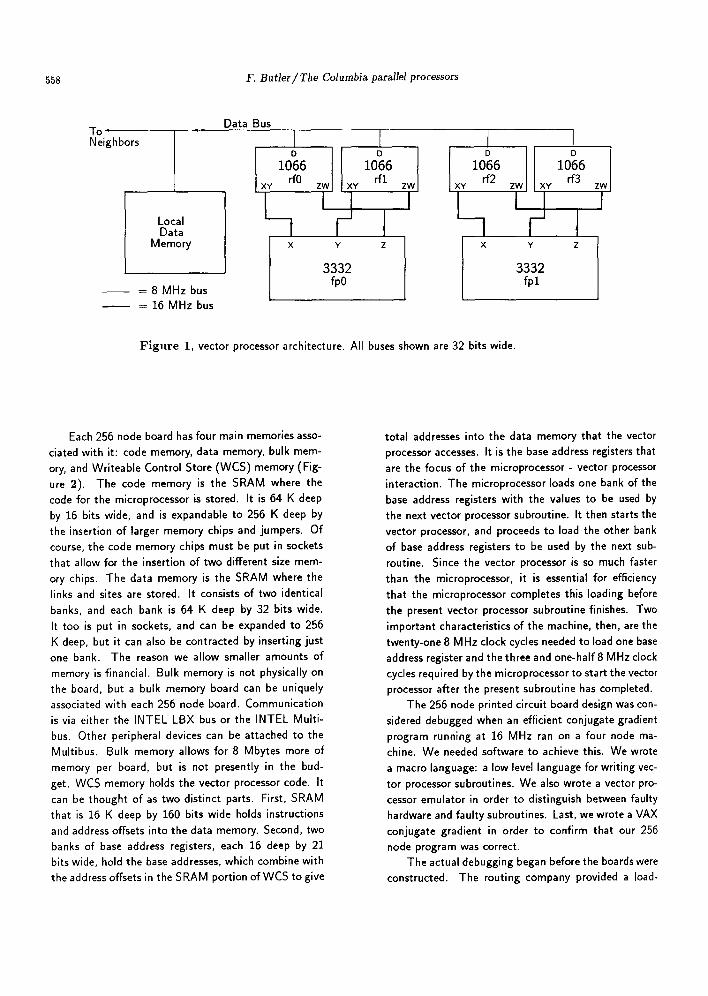
chines, is a 2-dimensional array of identical elements. Each node consists of an INTEL 80286 microprocessor and two vector processors; each vector processor con- sists of two Weitek 1066 register files and one Weitek 3332 floating point unit. Both floating point chips are obligated by hardware to execute identical microcode concurrently. The microprocessor is in charge, prepar- ing the board before each vector processor subroutine, and then starting the vector processor. The vector pro- cessor does all the work, executing the floating point operations on the link matrices and site vectors. It is the improved vector processor portion of the board that accounts for the factor of four gained in comput- ing power per board over the earlier machines. The purpose of the floating point units is clear; they do the floating point operations. The register files, on the other hand, reduce a bus bandwidth problem be- tween the floating point units and the data memory, where link matrices and site vectors are stored. The vector processor can access the local, -l-X, or -I-Y data memory on each 8 MHz cycle. Each of two floating point units can do one floating point addition and one floating point multiplication every 16 MHz cycle. The mismatch is apparent. Figure 1, the general vector processor architecture, displays how the 1066's ease this mismatch. There are thirty-two 32 bit registers in each of the 1066's and thirty-two 32 bit registers in- ternal to the 3332 that the floating point units can access at 16 MHz. The relatively small bus band- width between the data memory and the 1066's remains the major obstacle to achieving efficient programming.
"This research is supported in part by the U. S. Department of Energy.
0920-5632/89/$03.50 © Elsevier Science Publishers B.V. (North-Holland Physics Publishing Division)
558 F. Butler~The Columbia parallel processors
T O q i i
Neighbors
Local Data
Memory
- 8 MHz bus = 16 MHz bus
Data Bus
xY
I
I
° I ° 1066 1066
dO ZW XY r f l
II x Y z
3332 fp0
zw
I
I D
1066 rf2 xY ZW XY
Y
3332 fp l
I D
1066 rf3 zwl
I
F i g u r e 1, vector processor architecture. All buses shown are 32 bits wide.
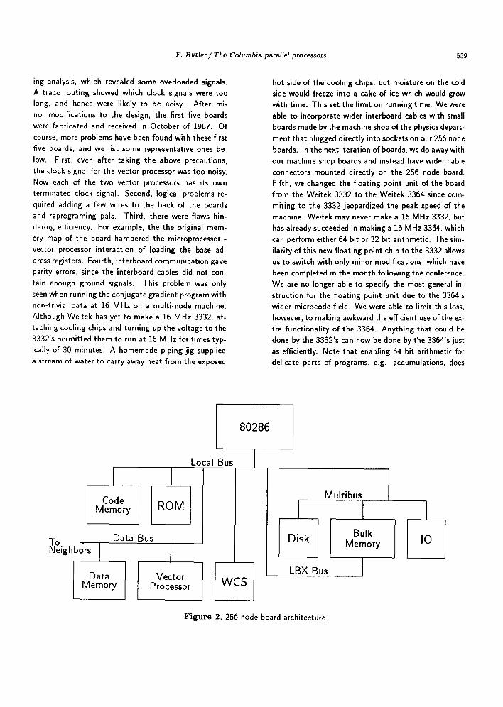
Each 256 node board has four main memories asso- ciated with it: code memory, data memory, bulk mem- ory, and Writeable Control Store (WCS) memory (Fig- ure 2). The code memory is the SRAM where the code for the microprocessor is stored. It is 64 K deep by 16 bits wide, and is expandable to 256 K deep by the insertion of larger memory chips and jumpers. Of course, the code memory chips must be put in sockets that allow for the insertion of two different size mem- ory chips. The data memory is the SRAM where the links and sites are stored. It consists of two identical banks, and each bank is 64 K deep by 32 bits wide. It too is put in sockets, and can be expanded to 256 K deep, but it can also be contracted by inserting just one bank. The reason we allow smaller amounts of memory is financial. Bulk memory is not physically on the board, but a bulk memory board can be uniquely associated with each 256 node board. Communication is via either the INTEL LBX bus or the INTEL Multi- bus. Other peripheral devices can be attached to the Multibus. Bulk memory allows for 8 Mbytes more of memory per board, but is not presently in the bud- get. WCS memory holds the vector processor code. It can be thought of as two distinct parts. First, SRAM that is 16 K deep by 160 bits wide holds instructions
and address offsets into the data memory. Second, two banks of base address registers, each 16 deep by 21 bits wide, hold the base addresses, which combine with the address offsets in the SRAM portion of WCS to give
total addresses into the data memory that the vector processor accesses. It is the base address registers that are the focus of the microprocessor - vector processor interaction. The microprocessor loads one bank of the base address registers with the values to be used by the next vector processor subroutine. It then starts the vector processor, and proceeds to load the other bank of base address registers to be used by the next sub- routine. Since the vector processor is so much faster than the microprocessor, it is essential for efficiency that the microprocessor completes this loading before the present vector processor subroutine finishes. Two important characteristics of the machine, then, are the twenty-one 8 MHz clock cycles needed to load one base address register and the three and one-half 8 MHz clock cycles required by the microprocessor to start the vector processor after the present subroutine has completed.
The 256 node printed circuit board design was con- sidered debugged when an efficient conjugate gradient program running at 16 MHz ran on a four node ma- chine. We needed software to achieve this. We wrote a macro language: a low level language for writing vec-
tor processor subroutines. We also wrote a vector pro- cessor emulator in order to distinguish between faulty hardware and faulty subroutines. Last, we wrote a VAX conjugate gradient in order to confirm that our 256 nocle program was correct.
The actual debugging began before the boards were constructed. The routing company provided a load-
F. Butler~The Columbia parMlel processors 559
ing analysis, which revealed some overloaded signals. A trace routing showed which clock signals were too long, and hence were likely to be noisy. After mi- nor modifications to the design, the first five boards were fabricated and received in October of 1987. Of course, more problems have been found with these first five boards, and we list some representative ones be- low. First, even after taking the above precautions, the clock signal for the vector processor was too noisy. Now each of the two vector processors has its own terminated clock signal. Second, logical problems re- quired adding a few wires to the back of the boards and reprograming pals. Third, there were flaws hin- dering efficiency. For example, the the original mem- ory map of the board hampered the microprocessor - vector processor interaction of loading the base ad- dress registers. Fourth, interboard communication gave parity errors, since the interboard cables did not con- tain enough ground signals. This problem was only seen when running the conjugate gradient program with non-trivial data at 16 MHz on a multi-node machine. Although Weitek has yet to make a 16 MHz 3332, at- taching cooling chips and turning up the voltage to the 3332's permitted them to run at 16 MHz for times typ- ically of 30 minutes. A homemade piping jig supplied a stream of water to carry away heat from the exposed
hot side of the cooling chips, but moisture on the cold side would freeze into a cake of ice which would grow with time. This set the limit on running time. We were able to incorporate wider interboard cables with small boards made by the machine shop of the physics depart- ment that plugged directly into sockets on our 256 node boards. In the next iteration of boards, we do away with our machine shop boards and instead have wider cable connectors mounted directly on the 256 node board. Fifth, we changed the floating point unit of the board from the Weitek 3332 to the Weitek 3364 since com- miting to the 3332 jeopardized the peak speed of the machine. Weitek may never make a 16 MHz 3332, but has already succeeded in making a 16 MHz 3364, which can perform either 64 bit or 32 bit arithmetic. The sim- ilarity of this new floating point chip to the 3332 allows us to switch with only minor modifications, which have been completed in the month following the conference. We are no longer able to specify the most general in- struction for the floating point unit due to the 3364's wider microcode field. We were able to limit this loss, however, to making awkward the efficient use of the ex- tra functionality of the 3364. Anything that could be done by the 3332's can now be done by the 3364's just as efficiently. Note that enabling 64 bit arithmetic for delicate parts of programs, e.g. accumulations, does
80286
Code M e m o r y
NTo , Data Bus
e ighbors I
Data M e m o r y
ROM
Vec to r P rocessor
Local Bus
W,_-S[
oisk 1 L B X Bus
M u l t i b u s
I Bu lk
M e m o r y
Figure 2, 256 node board architecture.
I IO
560 F. Butler~The Columbia parallel processors
not have to compound our bus bandwidth problem; only 32 bit numbers need be written to and read from the 3364. The 3364 can convert between single and double precision internally and can store just as many 64 bit values as 32 bit values.
Switching to the 3364 required more than just rewiring the boards. We no longer had a conjugate gradient program running at 16 MHz on a muhi-node machine nor the software tools for writing one. In the
past month, both the macro language and the con- jugate gradient microcode have been re-written. Al- though a new vector processor emulator is still needed, the new conjugate gradient agrees with the 3332 ver- sion. Unfortunately, we've obtained only two 16 MHz 3364's, so we do not have a multi-node test, but we are confident enough to have already started the rout- ing and fabrication of the next iteration of 18 boards. This will provide the full test of our design modifica- tion, and will allow us to proceed with the constuction of 282 more boards.
Rewriting the conjugate gradient microcode is sig- nificant since the macro language is very low level. In a microcode MAC256 file, one can declare scalars, vec- tors, and matrices. These can be either of real or com- plex type. Notice that since all floating point operations occur in both 3364's concurrently, MAC256 requires that variables in the internal registers of the 3364's be declared in pairs. We then are required to access both variables simultaneously with a single macro. Variables in the 1066's can also be declared in pairs that can be simultaneously accessed by both floating point units. Unlike 3364 variables, a special syntax is required for this pairing of 1066 variables. Variables can also be de- clared in the local, +X, or +Y data memory, but there is no need for such pairing.
We give two examples to clarify. First, i z r is a variable declared in the internal register files of both 3364's. Whenever i z r is specified as an argument of a macro, the operation is performed on both correspond- ing 3364 register contents, as required by hardware.
var r izr irf [28]
Second, fl$O and fl$1 are variables that reside in the zeroth and second 1066 register file, rf0 and rf2, re- spectively. Refer to Figure 1.
var r fl$O rf [0,31]
var r fl$1 rf [2,31]
If we wish to write both of these variables into their re- spective floating point units, we specify the appropriate macro with f l $ _ as the argument. If we wish to write only f l $ 0 to the data memory, for example, we specify the appropriate macro with f l $ 0 as the argument.
Macros allow for both data movement and arith- metic of only real and complex scalars. Thus, they are sufficently simple that a MAC255 file can attain the same effiency as a microcode file written in l 's and O's. Our hardware does not allow for loops, and we have yet to write a preprocessor that will unravel MAC255 loops. The simplicity of the macro's and the lack of loops makes programming in MAC256 a tedious procedure done with extensive use of the cut and paste features of an editor. Numerous opportunities for typographical errors therefore arise, e.g. changing indices of vector and matrix elements. Although the MAC256 files are readable, the clock cycle is controlled by the program- mer, which makes data dependence rather intractable. Thus, the programmer must know all the hardware la- tencies. To exemplify the difficulty of MAC255 pro- gramming, we state that it took one student six months to write the conjugate gradient program described be- low. Approximately half of this time was spent writ- ing the code for the microprocessor and becoming ac- quainted with the vector processor hardware, and half was spent actually microcoding in MAC256. Another month was required by the programmer to update the
microcode from the original 3332 version to the new
3364 version. The number of lines of microcode is given below.
Here, we give an example of a typical line taken from one of the microcode subroutines. We specify one vector processsor read from the data memory into one of the 1066 register files. Since each line of mi- crocode corresponds to one 8 MHz cycle, we specify two 16 MHz load operations, moving data from 1066 register to 3364 register. Of course, each of these load instructions are really a pair of operations, one occur- ring in each vector processor, due to the $_ syntax. We are also able to specify two 16 MHz multiplies and two 16 MHz additions in this 8 MHz cycle in each of two floating point processors, i.e. a total of eight floating point operations. Notice that one of the arguments of each multiply resides in a 1066 register file. TO and T1
F. Butler/The Columbia parMle/processors 561
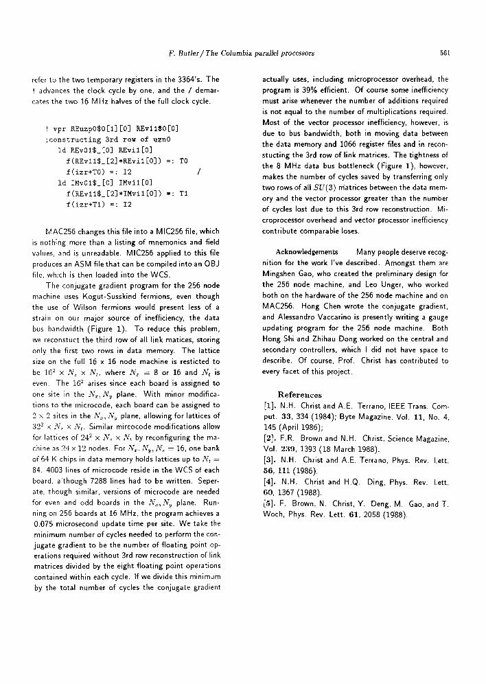
refer to the two temporary registers in the 3364's. The ! advances the clock cycle by one, and the / demar- cates the two 16 MHz halves of the full clock cycle.
! vpr KEuzp0$0 [l] [0] KEvlI$0[0]
;constructing 3rd row of uzn0
id KEv01$_[0] KEvil[0]
f(KEvll$_[2]*KEvil[0]) =: TO
f(izr+T0) =: I2
id ISv01$_[0] IMviI[0]
f(KEvll$_[2J*IMvil[0]) :: TI
f(izr+Tl) =: I2
MAC256 changes this file into a MIC256 file, which is nothing more than a listing of mnemonics and field values, and is unreadable. MIC256 applied to this file produces an ASM file that can be compiled into an OBJ file, which is then loaded into the WCS.
The conjugate gradient program for the 256 node machine uses Kogut-Susskind fermions, even though the use of Wilson fermions would present less of a strain on our major source of inefficiency, the data bus bandwidth (Figure i ) . To reduce this problem, we reconstuct the third row of all link matices, storing only the first two rows in data memory. The lattice size on the full 16 x 16 node machine is resticted to be 102 × N~ x Nt, where Nz = 8 or 16 and N~ is even. The 162 arises since each board is assigned to one site in the Nx~Ny plane. With minor modifica- tions to the microcode, each board can be assigned to 2 × 2 sites in the N~, Ny plane, allowing for lattices of 322 x N~ × Nt. Similar mircocode modifications allow for lattices of 242 x Nz × Nt by reconfiguring the ma- chine as 24x12 nodes. ForNx~Ny~Nz = 16, one bank of 64 K chips in data memory holds lattices up to .N-t = 84. 4003 lines of microcode reside in the WCS of each board, although 7288 lines had to be written. Seper- ate, though similar, versions of microcode are needed for even and odd boards in the Nx~Ny plane. Run- ning on 256 boards at 16 MHz, the program achieves a 0.075 microsecond update time per site. We take the minimum number of cycles needed to perform the con- jugate gradient to be the number of floating point op- erations required without 3rd row reconstruction of link matrices divided by the eight floating point operations contained within each cycle. If we divide this minimum by the total number of cycles the conjugate gradient
actually uses, including microprocessor overhead, the program is 39% efficient. Of course some inefficiency must arise whenever the number of additions required is not equal to the number of multiplications required. Most of the vector processor inefficiency, however, is due to bus bandwidth, both in moving data between the data memory and 1066 register files and in recon- stucting the 3rd row of link matrices. The tightness of the 8 MHz data bus bottleneck (Figure 1), however, makes the number of cycles saved by transferring only two rows of all SU(3) m'atrices between the data mem- ory and the vector processor greater than the number of cycles lost due to this 3rd row reconstruction. Mi- croprocessor overhead and vector processor inefficiency contribute comparable loses.
Acknowledgements Many people deserve recog- nition for the work I've described. Amongst them are Mingshen Gao, who created the preliminary design for the 256 node machine, and Leo Unger, who worked both on the hardware of the 256 node machine and on MAC256. Hong Chen wrote the conjugate gradient, and Alessandro Vaccarino is presently writing a gauge updating program for the 256 node machine. Both Hong Shi and Zhihau Dong worked on the central and secondary controllers, which I did not have space to describe. Of course, Prof. Christ has contributed to every facet of this project.
References [1]. N.H. Christ and A.E. Terrano, IEEE Trans. Com- put. 33, 334 (1984); Byte Magazine, Vol. 11, No. 4, 14S (April 1986); [2]. F.R. Brown and N.H. Christ, Science Magazine, Vol. 239, 1393 (18 March 1988). [3]. N.H. Christ and A.E. Terrano, Phys. Rev. Lett. 56, 111 (1986). [4]. N.H. Christ and H.Q. Ding, Phys. Rev. Lett. 60, 1367 (1988). [5]. F. Brown, N. Christ, Y. Deng, M. Gao, and T. Woch, Phys. Rev. Lett. 61, 2058 (1988).