status of the advanced virgo detector - osaka city …status_of...status of the advanced virgo...
TRANSCRIPT
Status of the Advanced Virgo detector
F. Piergiovanni
on behalf of
The Virgo Collaboration
GWPAW, Osaka, 06/17/2015

• The Advanced Virgo challenges
• Where we stand and what we are going to do
• Construction and integration highlights
• Perspectives and conclusions
Talk outline
2

The project involves: 5 countries, 20 labs and ~200 authors.
Advanced Virgo is a major upgrade of the Virgo ground based gravitational wave interferometric detector
The Advanced Virgo project
3

2003 2004 2005 2006 2007 2008 2009 2010
Virgo + Start of the Virgo commissioning
First Virgo scientific run VSR1
• 1st generation of interferometric GW detectors: LIGO, Virgo, GEO600
Unlikely detection Validation of GW ground based interferometric technologies
Likely detection Beginning of routine observation towards a GW astronomy
Start of commissioning
• 2nd generation of interferometric GW detectors : aLIGO, AdVirgo, GEOHF, KAGRA, LIGO India
2009 2010 2011 2012 2013 2014 2015 2016
Today
Joining aLIGO for O2
Start of construction
Technical Design Report released
AdVirgo founding approved
The short history
4
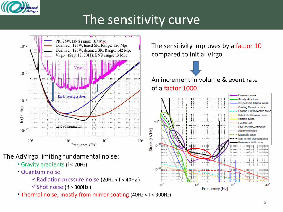
The sensitivity improves by a factor 10 compared to initial Virgo An increment in volume & event rate of a factor 1000
The AdVirgo limiting fundamental noise: • Gravity gradients (f < 20Hz)
• Quantum noise Radiation pressure noise (20Hz < f < 40Hz )
Shot noise ( f > 300Hz )
• Thermal noise, mostly from mirror coating (40Hz < f < 300Hz)
The sensitivity curve
5

• Lowering the thermal noise of suspensions and mirrors:
Doubling the mirror weight (42kg) Suspending the mirrors with fused silica fibres Enlarging the beam size on the test masses Mirror coatings engineered for low dissipations
The low and medium frequency range
• Lowering the residual gas noise: installing cryotraps
•Limiting the environmental noise: Photodiodes under vacuum on suspended benches Baffles to shield tubes, mirrors, vacuum chambers preventing scattered light diffusion
The main changes: how to gain a factor 10
6
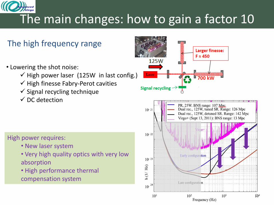
The high frequency range
• Lowering the shot noise: High power laser (125W in last config.) High finesse Fabry-Perot cavities Signal recycling technique DC detection
High power requires: • New laser system • Very high quality optics with very low absorption • High performance thermal compensation system
The main changes: how to gain a factor 10
7

The mail goal is to join aLIGO in 2016 observational runs
Reach the early configuration sensitivity : • no signal recycling • no high power laser ( up to 25W )
A step by step approach
BNS inspiral range evolution (1.4-1.4 Mo )
15 Mpc
100 Mpc 150 Mpc
Virgo+ AdVirgo early AdVirgo full
8
Reducing : • locking complexity (optics configuration similar to Virgo+) • the thermal effects and the compensation system requirements
Further steps towards the full sensitivity will be planned with the partners

Construction and integration highlights
9

The light source and injection
• High power laser (postponed) • A lot of sensing devices and electronics under vacuum • Large beam and high power new design of optical benches
Construction and integration highlights
10

• A 60W laser system (Virgo+) is already installed and in operation • The power stabilization works at 23W and all the noise spectrum is well understood
• The high power laser amplifier is under tests: the AdVirgo requirements are satisfied in terms of lifetime stability and intensity noise Full scale integration test are ongoing.
Light source and injection
11

About 90% of the hardware has been installed
Complete
Not yet integrated
Light source and injection
12

SIB1 Installed & integrated in tower
The EIB in the Laser lab
The IMC end mirror in tower SIB2 completed Minitower installed
Integration is ongoing
Light source and injection
13

• The Input Mode Cleaner commissioning has started one year ago
• Duty cycle continuously improving (99% during weekends)
• Tested up to 31W of input power
• Reference cavity locked since November 2014 • The noise has been reasonably well understood
• The noise hunting is ongoing
Light source and injection
14

Mirrors
• High power needs very high quality substrates and coatings:
Low absorption Great homogeneity
• Thermal noise reduction needs:
heavier and thicker mirrors low dissipative coatings
Construction and integration highlights
15

• All the AdVirgo large mirrors have been completed on schedule
The mirror figures are better than the specifications
Risk reduction for aberration and scattered light
Mirror “maps” are used in simulations to predict the interferometer behavior
Mirrors
16

• The “ears” have been silicate bonded to the mirror flats on 3 over 4 test masses • Each bonding strength is tested
The beam splitter has been the first large mirror integrated in tower A large beam needs a large BS: 550 mm diameter
Mirrors
17

The Suspensions Long suspension
Short suspensions A lot of changes on the last stage: • Compliant with the new mirrors • New Fused silica fibres design • Need to host many new optical and mechanical parts
Even if Virgo SAS performances already fit the AdVirgo general specifications: • New filter 7 matching the new payloads •Tilt controls • New electronics
Construction and integration highlights
18

• Completely redesigned to host the new mirrors and many other optical and mechanical components: ring heater, compensation plates, baffles, adjustment motor…
The last stage
RH vertical tilt motion
Mirror coils holder
RH shield
Front baffles
Rear baffles
CP suspension
CP vertical tilt motion
RH horizontal tilt motion
Many critical elements to be crammed into the available space and weight
Suspensions
19

• Improving the fibers production and characterization, increasing the fiber length and profile accuracy and reproducibility
The AdVirgo specification on mirror positioning and maximum tilt angle (1mrad) can be fulfilled • Better accuracy of the bending points placement
The Mirrors fused silica suspension The monolithic test mass suspension of Virgo+ has been largely upgraded: • Less dissipative fused silica-steel upper clamp • Dumbbell fiber shape to cancel thermoelastic dissipation
Suspensions
20
800 μm
400 μm
800 μm
Bending points
Rod 3000 μm

Works are ongoing to upgrade the suspension system:
The upgrades/integration table:
The electronics has been redesigned from scratch: integration foreseen in fall 2015
Suspensions
21

The thermal compensation
Construction and integration highlights
High performance system to reduce aberration due to thermal effects and cold mirror defects: • optical path length distortions • change of the mirror surface profiles • correction of the radius of curvature errors
Actuators: • CO2 laser shining compensation plates • Ring heater Sensing: • Hartmann sensor • Phase camera
22

• CO2 laser has been characterized • CO2 laser benches almost complete • Acoustic enclosure already on site
• The ring heaters production and integration will follow the payloads integration planning •The first installed RH follows the prototypes behavior
The actuators
Thermal compensation
23

Thermal compensation
The sensors
• The Hartmann wavefront sensor:
The design has been finalized
The installation is in progress
Many tests are underway on a dedicated test facility
• The phase camera:
Installation and tests on the devices are underway Integration with the compensation system is in progress
24

The signal detection
To extract AdVirgo signals: • Adjust the detection optics to the enlarged beam (new telescope design) • Separate the overlapping beams
• Rejects high order modes enhancing the dark fringe contrast • Rejects optical fields to be compliant with DC detection
Construction and integration highlights
25

Signal detection
• The detection system main optical bench has been installed • Integration is foreseen soon
A new Output Mode Cleaner has been realized: • Developed for DC detection • Two monolithic cavities in series • Filtering high order modes and optical field
26

Signal detection
• Five new minitowers have been produced to suspend in vacuum photodiodes benches •Pre-commissioning with dummy mass in progress
Mini-towers:
Installation Integration
complete in progress
to install
27

The vacuum system
Construction and integration highlights
• The residual pressure must be reduced by two orders of magnitude, a factor ten in noise contribution • Cryotraps installed to isolate towers from pipes
• Large spot size requires enlarging the vacuum links and viewports • New vacuum chambers to host PD benches
28

Vacuum system
Cryotraps & enlarged links
• Cooling-down test achieved for the two cryotraps placed at the end towers • The main vessels are installed at the inputs and the integration is quite complete
• two smaller cryostats are being installed at the short tower
• enlarged links installation is almost completed
29
Commissioning
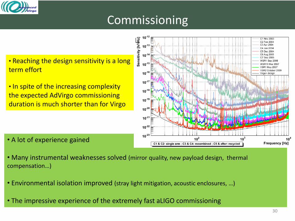
• Reaching the design sensitivity is a long term effort
• In spite of the increasing complexity the expected AdVirgo commissioning duration is much shorter than for Virgo
Virgo commissioning: 6 years / 7 order of magnitude
• A lot of experience gained • Many instrumental weaknesses solved (mirror quality, new payload design, thermal compensation…)
• Environmental isolation improved (stray light mitigation, acoustic enclosures, …)
• The impressive experience of the extremely fast aLIGO commissioning
30

Commissioning
• The commissioning is already started on light injection system and IMC • Many tests have been anticipated to save time also on other sub-systems
IMC era (now)
Central Interferometer era
Arm-Cavity era
Power Recycling era
Final steps to reach the early sensitivity curve (mid 2016)
The plan in a sketch:
31
• The step by step procedure foresees:

Conclusion
• Advanced Virgo is currently in a crucial phase of installation • A lot of parallel activities are ongoing requiring a big and constant organization effort • The schedule is very tight and all the arising issues have to be promptly faced coordinating the works of all the groups • All the groups are fully committed to end the installation/integration phase within 2015 to achieve the first lock in the first months of 2016 • The main target is to join LIGO in observational run during 2016 • The steps towards the transition to the full configuration will be decided with the partners
32

33