status of engine critical component project - digital …/67531/metadc682588/m2/1/high... · status...
TRANSCRIPT

Status of the Boeing Dish Engine Critical Component Project
Kenneth W. Stone Boeing 5301 Bolsa Ave. Huntington Beach, CA 92647 PH: 714-896-331 1 X69193 FAX: 71 4-896-391 0
Hans Nelving Kockums S-205 55 Malmo, Sweden
Dir: 46-40-34-82-75 PH: 46-40-34-80-00
FAX: 46-40973281
ABSTRACT The Boeing Company's Dish Engine Critical
Component (DECC) project started in April of 1998. It is a continuation of a solar energy program started by McDonnell Douglas (now Boeing) and United Stirling of Sweden in the mid 1980s. The overall objectives, schedule, and status of this project are presented in this paper. The hardware test configuration, hardware background, operation, and test plans are also discussed. A summary is given of the test data, which includes the daily power performance. generated energy, working-gas usage, mirror reflectivity, solar insolation, on-sun track time, generating time, and system availability. The system performance based upon the present test data is compared to test data from the 1984/88 McDonnell DouglaslUnited Stirling ABlSouthem California Edison test program. The test data shows that the present power, energy, and mirror performance is comparable to when the hardware was first manufactured 14 years ago.
I'
Harry W. Braun Terence B. Clark Stirling Energy Systems 6245 North 24th Pkwy Phoenix, AZ 8501 6 PH: 602-957-1 81 8 FAX: 602-957-1 91 9
Richard B. Diver Sandia National Laboratories P.O. Box 5800 AI buquerque, NM 871 85-0703 PH: 505-844-01 95 FAX: 505-844-7786
INTRODUCTION The Boeing Dish Engine Critical Component (DECC)
project is an instrumental part of the development of the dish Stirling system started in the 1970s (see Fig. 1). Stirling Energy Systems (SES) has initiated a commercialization program for dish Stirling that is a continuation of a McDonnell Douglas (MDC) and United Stirling AB of Sweden (USAB is a division of Kockums) program that was started over 16 years ago. SES has obtained the rights and patents for the MDC concentrator design, and has a license to manufacture the Kockums 4-95 Stirling engine.
In the early 1970s. United Stirling AB started development of the 4-95 kinematic Stirling engine (Fig. 2). In the late 1970s and early 1980s. USAB, under contract from the Jet Propulsion Laboratory (JPL) and the US. Department of Energy (DOE), designed, fabricated, and tested "solarized" versions of the USAB 4-95 Stirling engine at the Georgia Tech Advanced Component Test Facility (ACTF) and at the JPL Solar Test Facility at Edwards Air Force Base. (Livingston, 1985) Because the
lggo I 1970 1975 1980 1985
I Non Solar 4-95 bevelopme;l I I I
m I ockums/JPL Solarizing I Progr:m
KockumslMDC I Prog. d l Vanguard K o c k u m s / ; l Program
I I Kockums Stirling Marine Program I Figure 2.4-95 Solar Stirling engine development.
DISCLAIMER
This report was prepared as an account of work sponsored by an agency of the United States Government. Neither the United States Government nor any agency thereof, nor any of their employees, make any warranty, express or implied, or assumes any legal liability or responsibility for the accuracy, completeness, or usefulness of any information, apparatus, product, or process disclosed, or represents that its use would not infringe privately owned rights. Reference herein to any specific commercial product, process, or service by trade name, trademark, manufacturer, or otherwise does not necessarily constitute or imply its endorsement, recommendation, or favoring by the United States Government or any agency thereof. The views and opinions of authors expressed herein do not necessarily state or reflect those of the United States Government or any agency thereof.

DISCLAIMER
Portions of this document may be illegible in electronic image products. Images are produced from the best available original document.
system demonstrated excellent performance, a DOE program was initiated with Advanco Corp. in which a USAB 4-95 Stirling Power Conversion Unit (PCU) was integrated with the Vanguard concentrator. This system demonstrated very high efficiency and established records for conversion efficiency of direct normal solar insolation to electricity. (Washom, 1984)
In the early 1980s, the McDonnell Douglas Company (now the Boeing Company) and USAB of Sweden formed a joint venture to commercialize a dish Stirling system based on the 4-95 Power Conversion Unit and a McDonnell Douglas-designed solar concentrator. Systems were installed at the McDonnell Douglas test site in Huntington Beach, CA and several utility test sites. Testing at these sites continued through late 1988. (Lopez and Stone, 1993)
In support of the SES commercialization of the BoeinglKockums disMStirling technology, SunLab has teamed with the Boeing Company, Stirling Energy Systems, and Kockums through the DECC program. (SunLab is a virtual DOE laboratory combining the expertise of Sandia National Laboratories and the National Renewable Energy Laboratory.)
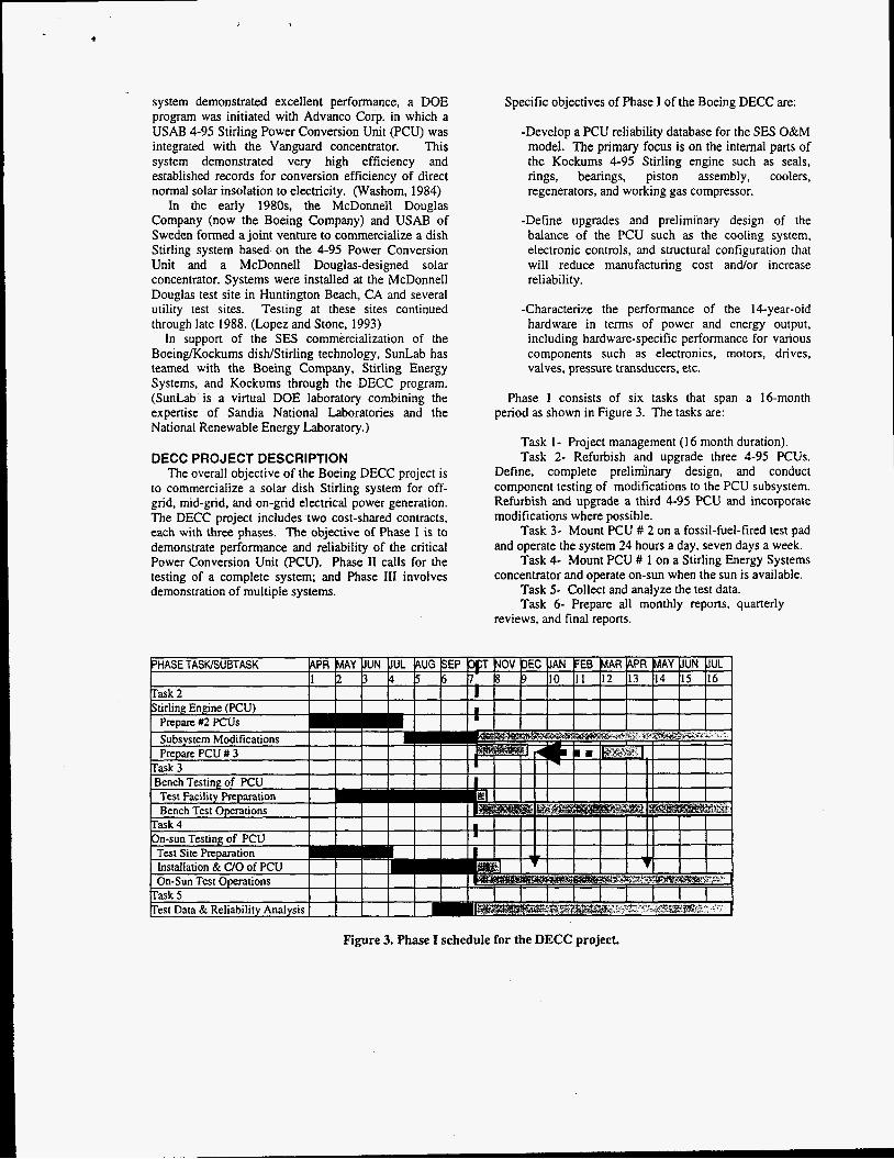
DECC PROJECT DESCRIPTION The overall objective of the Boeing DECC project is
to commercialize a solar dish Stirling system for off- grid, mid-grid, and on-grid electrical power generation. The DECC project includes two cost-shared contracts, each with three phases. The objective of Phase I is to demonstrate performance and reliability of the critical Power Conversion Unit (PCU). Phase I1 calls for the testing of a complete system; and Phase 111 involves demonstration of multiple systems.
Specific objectives of Phase I of the Boeing DECC are:
-Develop a PCU reliability database for the SES O&M model. The primary focus is on the internal parts of the Kockums 4-95 Stirling engine such as seals, rings, bearings, piston assembly, coolers, regenerators, and working gas compressor.
-Define upgrades and preliminary design of the balance of the PCU such as the cooling system, electronic controls, and structural configuration that will reduce manufacturing cost andor increase reliability.
-Characterize the performance of the 14-year-old hardware in terms of power and energy output, including hardware-specific performance for various components such as electronics, motors, drives, valves, pressure transducers, etc.
Phase I consists of six tasks that span a 16-month period as shown in Figure 3. The tasks are:
Task 1 - Project management ( 1 6 month duration). Task 2- Refurbish and upgrade three 4-95 PCUs.
Define, complete preliminary design, and conduct component testing of modifications to the PCU subsystem. Refurbish and upgrade a third 4-95 PCU and incorporate modifications where possible.
Task 3- Mount PCU # 2 on a fossil-fuel-fired test pad and operate the system 24 hours a day, seven days a week.
Task 4- Mount PCU # 1 on a Stirling Energy Systems concentrator and operate on-sun when the sun is available.
Task 5- Collect and analyze the test data. Task 6- Prepare all monthly reports, quarterly
reviews, and final reports.
Figure 3. Phase I schedule for the DECC project.

The basic program is to refurbish two 4-95 PCUs, operate the first PCU on-sun, and operate the second PCU on the bench. A third PCU was originally planned to be refurbished towards the end of the program, but this has been moved forward and testing is now planned in early 1999.
SYSTEM DESCRIPTION General characteristics of the Kockums 4-95 Stirling
engine are given in Table 1 and a cross- section view is given in Figure 4. The figure shows the engine with a directly illuminated solar receiver. The engine is a "U" shape with four pistons connected to two crankshafts. The PCU is mounted on one of the SES concentrators, which were specifically developed by McDonnell Douglas for the Kockums PCU. The concentrator has a total aperture reflective area of 87.7 m2 and concentrates over 75 kW of thermal energy on the receiver at a sun insolation of I ,OOO W/m2. (Lopez and Stone, 1993) The concentrator used for the DECC program is located at the Boeing Solar Test Site in Huntington Beach, CA.
Table 1. 4-95 Stirling engine characteristics.
Engine type Power Electrical Weight Displacement Cylinders Operating Speed Working fluid Engine temperature
Kinematic Stirling 25 kW, @ 1000 W/m2 480 V AC, 3 0 1500 Ibs. Each piston, 95 cc3 4, Double-acting pistons 1800 rpm Hydrogen 720 "C
PROJECT STATUS The project is proceeding on the schedule shown in
Figure 3. The first two PCUs were refurbished by Kockums in 1997 under a contract from SES. PCU #I was mounted on the concentrator at the Boeing Solar Test Facility in late June of 1998, went on-sun for the first time on June 26", and produced the first positive power on July 2". Through early November, the system has operated daily as weather permits, and has accumulated over 900 hours. The weekly and accumulated on-sun operating hours are shown in Figure 5. The variation in the weekly on-sun time is the result of cloudy conditions.
PCU #2 was mounted in a Kockums test cell in mid- October and has accumulated a little over 100 test hours. The testing started later than scheduled because of a shippingkustoms problem. The solar heater head was removed and replaced with a gas-fired heater head. The radiator has also been removed and the cooling system has been integrated into an exterior cooling system. The bench test PCU is scheduled to operate 24 hours per day, seven days a week. Testing will be interrupted periodically for inspection.
Figure 4. Engine cross-section.

c
PROGRAM
Through the various test programs, the Kockums 4- 95 Stirling engine has accumulated over 17,000 hours in on-sun operating time as shown in Table 2 and over 118,000 hours of bench operating time by Kockums as shown in Table 3. Many of these hours were accumulated in a simulated solar mode where the power and engine elevation angles were varied to simulate the solar insolation profile and sun elevation angle.
The weekly and accumulated net generated energy since June 26, 1998 is shown in Figure 6. The system is averaging about 700 kWh electrical output per week, and has generated over 10 MWhc to date. The main reason for the variation in the weekly generated power is due to cloudy conditions. The energy level is also considerably lower than what would be generated at a site like Barstow, CA because of the lower insolation level and coastal clouds at Huntington Beach.
TIME (h)
Table 2. Total on-sun operating time.
~~~~ ~
Boeing DECC MDC/USAB/SCE USABNanguard USABIJPL
~~
900 13,752 2,412
420
TOTAL 17,484 h
- 1000
800 700
5 600 500 400 300
g 200 5 100 $ 0
0 10 20 30 40 50 60 WEEK IN OPERATING (wks)
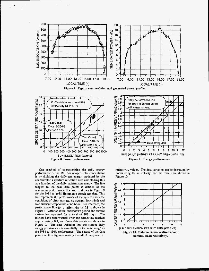
ON-SUN PERFORMANCE A typical power profile for the’system is shown in
Figure 7. The sun’s insolation is shown on the left and it follows an inverted “U” curve typical of a clear day at Huntington Beach. The generated power follows the insolation profile very closely.
The power performance of the system as a function of the sun insolation for steady state performance is shown in Figure 8. Also shown in this figure is the mean power performance line obtained from test data taken in the 1984 to 1988 MDC/USAB/SCE test program. As shown, the performance of the present system compares favorably with equivalent data recorded 14 years ago, largely due to very little change in the mirror performance.
Table 3. Total bench operating time.
PROGRAM
Boeing DECC MDCNSAB - Simulated solar - Bench
- Simulated solar - Bench USMJPL - Simulated solar - Bench
USABNanguard
TIME (h)
TBD
50,707 35,578
17,577 5,030
700 8.480
118,072 h
0 10 20 30 40 50 60 WEEK IN OPERATION (wks)
Figure 6. Weekly and accumulated generated energy.
900
800
700
600
500
400
300
200
100
0 7.00 9.00 11.00 13.00 15.00 17.00 19.00 7.00 9.00 11.00 13.00 15.00 17.00 19.00
LOCAL TIME (h) LOCAL TIME (h) Figure 7. Typical sun insolation and generated power profile.
0 100 200 300 400 500 600 700 800 900 1000 SUN INSOLATION (W/m"2)
Figure 8. Power performance.
One method of characterizing the daily energy performance of the MDC-developed solar concentrator is by dividing the daily net energy produced by the concentrator's aperture reflective area and plotting this as a function of the daily incident sun energy. The line tangent to the peak data points is defined as the maximum performance line and is shown in Figure 9 for the 1984 to 1988 Huntington Beach test data. This line represents the performance of the system under the conditions of clean mirrors, no outages, low winds and low ambient temperature conditions. For reference, the performance line for a reflectivity of 0.8 is shown in Figure 9. After an initial shakedown period, the current system has operated for a total of 101 days. The mirrors have been washed when the reflectivity reached approximately 0.8, and these data points are shown in Figure 9. The data indicates that the system daily energy performance is essentially in the same range as the 1984 to 1988 performance. The spread of the data points in this figure is mainly a result of the spread in
3 s c 2.8
2.6 g 2.4 g 2 . 2 r r 2 2 1.8
2 1.2 l - 1 g 0.8
> 1.6 h? 1.4
W
>- 0.6 ;i 0.4 * 0.2
0
1
0 1 2 3 4 5 6 7 8 9 1 0 1 1 1 2 SUN DAILY ENERGY PER UNIT AREA (kWNm"2)
Figure 9. Energy performance.
reflectivity values. The data variation can be decreased by normalizing the reflectivity, and the results are shown in Figure 10.
t
g 1 z w c 0.5 w z
2 4 6 8 10 12
SUN DAILY ENERGY PER UNIT AREA (kWrW2) Figure 10. Data points normalized about
nominal clean reflectivity.
... ,
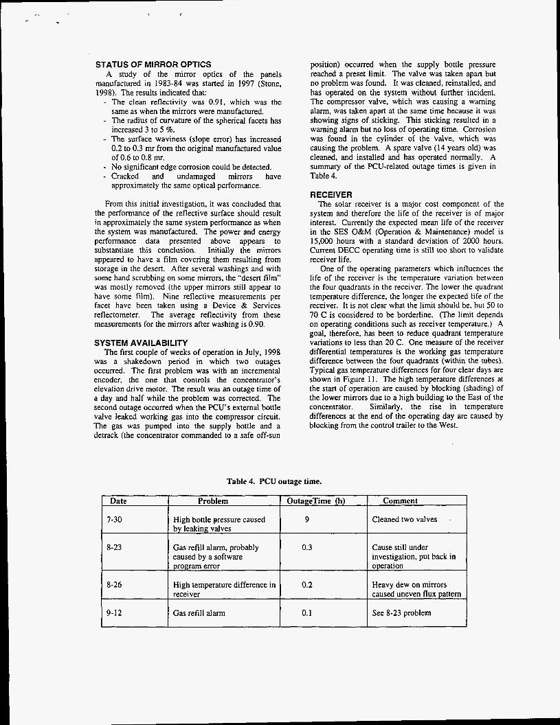
STATUS OF MIRROR OPTICS A study of the mirror optics of the panels
manufactured in 1983-84 was started in 1997 (Stone, 1998). The results indicated that:
- The clean reflectivity was 0.91, which was the same as when the mirrors were manufactured.
- The radius of curvature of the spherical facets has increased 3 to 5 %.
- The surface waviness (slope error) has increased 0.2 to 0.3 mr from the original manufactured value of 0.6 to 0.8 mr.
- No significant edge corrosion could be detected. - Cracked and undamaged mirrors have
approximately the same optical performance.
From this initial investigation, it was concluded that the performance of the reflective surface should result in approximately the same system performance as when the system was manufactured. The power and energy performance data presented above appears to substantiate this conclusion. Initially the mirrors appeared to have a film covering them resulting from storage in the desert. After several washings and with some hand scrubbing on some mirrors, the “desert film” was mostly removed (the upper mirrors still appear to have some film). Nine reflective measurements per facet have been taken using a Device & Services reflectometer. The average reflectivity from these measurements for the mirrors after washing is 0.90.
SYSTEM AVAILABILITY The first couple of weeks of operation in July, 1998
was a shakedown period in which two outages occurred. The first problem was with an incremental encoder, the one that controls the concentrator’s elevation drive motor. The result was an outage time of a day and half while the problem was corrected. The second outage occurred when the PCU’s external bottle valve leaked working gas into the compressor circuit. The gas was pumped into the supply bottle and a detrack (the concentrator commanded to a safe off-sun
position) occurred when the supply bottle pressure reached a preset limit. The valve was taken apart but no problem was found. It was cleaned, reinstalled, and has operated on the system without further incident. The compressor valve, which was causing a warning alarm, was taken apart at the same time because it was showing signs of sticking. This sticking resulted in a warning alarm but no loss of operating time. Corrosion was found in the cylinder of the Valve, which was causing the problem. A spare valve (14 years old) was cleaned, and installed and has operated normally. A summary of the PCU-related outage times is given in Table 4.
RECEIVER The solar receiver is a major cost component of the
system and therefore the life of the receiver is of major interest. Currently the expected mean life of the receiver in the SES O&M (Operation & Maintenance) model is 15,000 hours with a standard deviation of 2000 hours. Current DECC operating time is still too short to validate receiver life.
One of the operating parameters which influences the life of the receiver is the temperature variation between the four quadrants in the receiver. The lower the quadrant temperature difference, the longer the expected life of the receiver. It is not clear what the limit should be, but 50 to 70 C is considered to be borderline. (The limit depends on operating conditions such as receiver temperature.) A goal, therefore, has been to reduce quadrant temperature variations to less than 20 C. One measure of the receiver differential temperatures is the working gas temperature difference between the four quadrants (within the tubes). Typical gas temperature differences for four clear days are shown in Figure 11. The high temperature differences at the start of operation are caused by blocking (shading) of the lower mirrors due to a high building to the East of the concentrator. Similarly, the rise in temperature differences at the end of the operating day are caused by blocking from the control trailer to the West.
Table 4. PCU outage time.
Date I Problem I OutageTime (h) 1 Comment I 1
7-30 High bottle pressure caused 9 Cleaned two valves by leaking valves
8-23 Gas refill alarm, probably 0.3 Cause still under caused by a software program error operation
investigation, put back in
8-26 High temperature difference in 0.2 Heavy dew on mirrors receiver caused uneven flux pattern
I I See 8-23 problem 1 0.1 I Gas refill alarm I 9-12

90
80
70
60
E 50
40
$ 30
0, a,
W
W
LL
I- 20 (I)
4 10 I I I
, I I , ,
0.00 2.00 4.00 6.00 8.00 10.00 12.00 TIME FROM START O F OPERATION (h)
Figure 11. Receiver working gas temperature difference.
GAS ANALYSIS The life of the hydrogen seals is another component of
interest. The DECC project will obtain test data to substantiate the SES O&M model. A measure of the condition of the hydrogen seals is the relative change in engine pressure overnight. The engine shutdown and morning startup pressures are shown in Figure 12. The decrease in the pressure overnight is mainly due to the decrease in gas temperature from shutdown (680 C) to morning startup (typically 10 to 24 C). As the seals wear, the morning startup pressure will decrease. The figure indicates that in over 800 hours of operation there has not been a decrease in startup pressure, i.e.. no increase in leakage of hydrogen gas through the seals.
Shut down ltj pressure
I I
press u re
0 20 40 60 80 100 120 140 160 TIME FROM START OF PROJECT (days)
Figure 12. Engine gas pressure.
The PCU uses hydrogen gas as the heat transport medium and the gas consumption and resulting O&M
costs need to be qualified. The system has an external storage bottle, a “K’ bottle, mounted on the concentrator structure just below the PCU. When the pressure in the engine’s small (10 liter) supply bottle is lower than a preset value, gas from the external storage bottle is pumped into the supply bottle. Currently the planned O&M procedure for a power plant is either to replace the storage bottle or replenish it in the field.
An objective of the DECC project is to quantify gas consumption. Sufficient data has not yet been accumulated to develop a model, however the initial test data is shown in Figure 13. The present storage bottles are available with only 13.3 MPa (2000 psi) hydrogen, but steps are being made to obtain higher pressures. (A storage bottle pressure of around 40 MPa (6000 psi) was originally planned in order to minimize the number of times the bottles need to be replaced.) The first “ K ’ bottle was mostly consumed during the PCU initial checkout. In this period, gas was dumped from the system to check a valve or connection. A second bottle was installed, but the valve problem discussed above caused more gas to be lost. The rate of consumption for Bottle #2 was also above normal because of an undetected leak in one of the hydrogen valves. Because the pressure data was not plotted regularly at that time, the leak was not noticeable until the third bottle was installed, then the leak was detected and the loose fitting tightened. Based on preliminary data, the replacement of a 13.3 Mpa (2000 psi) “K” bottle for a nominally ”leak-free” system would be about every 60 days. If two 40 MPa (6OOO psi) “K” bottles were used (which the system was designed for), replacement would be only once a year and the hydrogen supply should not be a major O&M cost item. (This is predicated on minimizing leaks from valves and fittings. which is one of the goals in the DECC project.)
2500
.- + TANK1
w -i- TANK2
v) 2 1500 4 4 - TANK3 w IY a --F TANK4
g, 2000 v
IY
5 1000
2 2 500 c3
0 10 20 30 40 50 60 70 80 90 100
Figure 13. External bottle gas usage. TIME FROM CHANGEOUT OF TANK (days)
SUMMARY As of early November, 1998, the Boeing DECC project
has operated the SES Stirling Dish system on-sun for over 900 hours and has started operating a Kockums 4-95

Stirling PCU on the bench. After an initial checkout period, the system has generated power for essentially every hour that the sun has been available (above 200 Wlm') for 108 days.
Initial results of the reflective surface performance indicate the reflectivity has not changed and the curvature and surface waviness have only changed slightly. The system power and energy performance has been measured and appears to be approximately the same as when the system was manufactured 14 years ago. Further verification of system performance and development of a reliability data base are underway.
ACKNOWLEDGMENTS This project is partially funded by the Department of
Energy under Sandia Contract No. AV-5116B. Sandia is a multi-program laboratory operated by Sandia Corporation, a Lockheed Martin Company, for the U.S. Department of Energy under Contract DE-AC04-94-AL85000. The program manager would like to thank DOE for this
opportunity and also SunLab for their assistance and technical guidance. Thanks also to all of the dedicated people who have been working on this program.
REFERENCES: Livingston, F.R., 1985, "Activities and
Accomplishments in DisWStirling Electric Power System Development," DOWJPL-1060-82, Jet Propulsion Laboratory, Pasadena, CA.
Lopez, C.W., Stone, K.W., 1993, "Performance of the Southern California Edison Company Stirling Dish," SAND93-7098, Sandia National Laboratories, Albuquerque, NM.
Stone,K.W., Braun, H.W., Clark, T.B., "Status of the SES Solar Dish Reflective Surface," Solar 98: Renewable Energy for the Americas, Albuquerque, New Mexico, June
Washom, B., 1984, "Parabolic Dish Stirling Module Development and Test Results," Proceedings of the 19" IECEC, Paper No. 849516, San Francisco, CA.
13-18, 1998.