engine component retirement for cause v
TRANSCRIPT
T1C FuILE COPY
AFWAL-TR-87-4069Volume I -
ENGINE COMPONENTRETIREMENT FOR CAUSE V
VOLUME I - EXECUTIVE SUMMARY
John A. Harris, Jr.
United Technologies CorporationPratt & Whitney
N Engineering Division0) P.O. Box 109600Y~n West Palm Beach, Florida 33410-9600
August 1987
,i' Final Report for Period Auaust 1980 to November 1986 -.I-'
Approved for public release; distribution is unlimited
Materials LaboratoryAir Force Wright Aeronautical LaboratoriesAir Force Systems CommandWright-Pattersow Air Force Base, Ohio 45433-6533

m, ~Ew~ ~mid VK W .W wuw JV.'WfiWV11U-U I" WJVVU WU 1111`y w'.liwulr VVJ ~WWXVUV FFUN. gruuuE
UNCLASWFIEDSECURITY CLASSIFICATION OP THIS PAGE
REPORT DOCUMENTATION PAGE1g. NP1601T SECURI1TY CLASSIFICATION VLb 4PASTRICTIV11 MARKINGS
Unclassified Noneý2, Si~cuaiTY CLASSIFICATION AUTHORITY 3. OISTRIUUTION/AVAILABILITY OP REPORT
NIA Approved For Public Release,2b. OE0CLASSI PICATI ON/OOWNG RACING SCHEDULE Distribution Unlimited
a PtPFORMINO ORGANIZATION REPORT NUM§9RIUI L. (ANITORING ORGANIZATION REPORT NUMUSAISI
FIR-18301 AFWAL-Th-8-7--40-6-9 V-ol-u-me 1"
Ba A~IFRIGORGANIZATION Is. OFFICE SYMBOL. 746 NAME OF MOIORN ORGANIZATvqyUnited Technologies Corporation _Air Force Wr6ight eroniiutkil Labor-itoriesPra~tt & Whitney/Engineering Division1 ME&T Materials lAboratory (AFWALJMLLN)
6c. AOCARESS M#d,. State old ZIP Cod#) 7b. A0011R034 (City. Slatt aad ZIP Co"ej
P.O. Box 109600WestPal Beah, L 3310-600Wright-Pattereon Air Force Bas Ohio 45433-6533
110. NAMEl OF FUNDINGJSPONSORING Sb. OPPICE SYMBOL 9. PROCUREMENT INSTRUMENT IO1ENTIFICATION NUMBER
Defense Advanced RQeserc Plojti4'ncy (II PD-80iCbi5DAig Forceelright Aeronautical umortorne I AFWAL/MLLN
E& ADORISS, (city. State and ZIP Cow)D 10. 9OUCE OF rUNOING NOS. _____________
DARPA - 400 Wilson BIvd, Arlington, VA 22209 PROGRAM PROJECT TASK WORK UNIT
AFWAL -See Block 7B ELEMENT NO. No. NO. NO.
II.T TiLI (Incluide SecuitylI C~sudifeolioniv Brgine Componentfeleeit 64 0For Cause VolmeI - ecutive Summary ______ _________
12. PfE RINAL AUTI4ORIS1John A. Harris, Jr.S.P U1134. YYPI OF Rt PORT 11IL TIME COVE RO1.OATE OF REPORT (Yr.. Me.. DyA as. PAEcOUN
Fin al Report glRom. 1-O T 18987 August 6016. SUPPLIPA-6NTARY NOTA.TION .~ __
This is Volume I of the final report for this con ct. This volume is not a limited distribution. Other volumes ofthe final report ate limited acceus/disributi n.,
17. COVATI CODES 194 wd- t MS fC a.iet yogr. r --
' I IR U $ S B. o R. o c
19 21 4 05 ation, -7-1WEngine, Lie Cycle Cost, Engine Maintenance, Component
is program dveloped and integrated materials bevo hrceitccomponent life analysis,nonvi~structive evaluation and cost-risk technology to establish and demonstrate the retirement for cause
maintenanlce concept as it applies to rotating components of military gas turbine engines. As such it provides the/basis for elimination of classical time or cyclic life limits currently imposed for retirement of gas turbine rotorcomponents by substituting a life management syvstem in which each individual component is retired from servicewhen the unique, economical safe life of that component is exhausted.I
The methodology was demonstrated on and validated for the U.S. Ai, Force F100 engine's rotor componentsand has been implemented on that engine system by the USAF Air Logistics Command. Use of Retiremient forCause is projected to result in life cycle cost savings in excess of $1 bill-ion for that engine system. The Retirementfor Cause methodoleogy developed is generic, and may be applied to not only other gas turbine engines, but tocompon~ents of any life limited system.
This report prasents an overview/summary of the development activity and its results.k2( . ' .
20. OiSTPISBUTION/AVAILAGILITY OP ABSTRACT T21. ABSTRACT SECURITY CLASSIFICATION /
tUNCLAS3IF.'6OIUNLIMiTEO 2 SAME AS APT. 0 OTic usEn R0
22&. NAMIE OF NESPONSISLE1 IMPIVIOUAL I22b. TELEPHONE NUMBER 122c. OFICE SYMBOL
Dr.Joh P.Heneren I (include A r*eCade)Dr.___John___.__Henderson__ (513) -265-2498 AFWAL/MLLN
OD FOHM1473, 8 APR DITION OP I JAN 73 IS OBSOLETE. JNLS1YI1)
FOREWORD
This work was performed under the U.S. Air Force - Wright Aeronautical Laboratories, U(Materials Laboratory) Contract F33615-80-C-5160 with the Prn.ject Number assigned asDARPA 3993. This contract program was initiated in August 1980, and was completed inFebruary 1987. The Air Force Retirement for Cause Program Manager was Dr. W. H. Reimann(AFWAL/MLTC). The USAF Project Engineer for this contract was L. P. Zawada(AFWAL/MLLN). The work was performed by the Engineering Division and GovernmentProducts Division of Pratt and Whitney under the direction of the Retirement for CauseProgram Management Office of the Materials Engineering and Technology Branch, (ED-S).Program Manager of Pratt and Whitney Retirement for Cause activities is J.A. Harris, Jr.,reporting to M. C. VanWanderham, Manager, Mechanics of Materialh and Stru-tures. TechnicalProgram Managers for this effort were C.G. Annis, Jr., B.A. Cowles, and J.S. Cargill. ProjectEngineers were D.L. Sims, R. White and RIL. Shambaugh.
This program was jointly sponsored by the Materials Sciences Office, Defense AdvancedResearch Projects Agency and the Materials Laboratory, Air Force Wright AeronauticalLaborntories. The contributions, support arid cooperation of DARPA and the many U.S. AirForce participants are acknowledged as key factors in the success of the program.
The P&W Retirement for Cause Program Management Office also acknowledges thecontributions of the many Pratt and Whitney organizations to the program.
2._ S
IlU
S
TANAE OF CONTENMTSU
Section Pqe _"
ISU• [X M R Y ........................... .... .................. .........• I ........ 1o m mo•~ o , • ,ei , t
II INTRUDUCTION ..................................................................... 3
III THE F o00 ENGINE .................................................................. 16
IV RSTUSS ................................................ ........................... .23
V CONCLUSIONS ............................................................... 51
REFERENCES ..................................................................... .. 52
Accession For
NTIS GRA&IDTIC TABUnannounced
J Justification ,
ByDistribution/
Availability CodestA"'aiý:and/or
Dist Special
vI0.'t
41

UUff OF LLUSMThA1O
Figure POP.
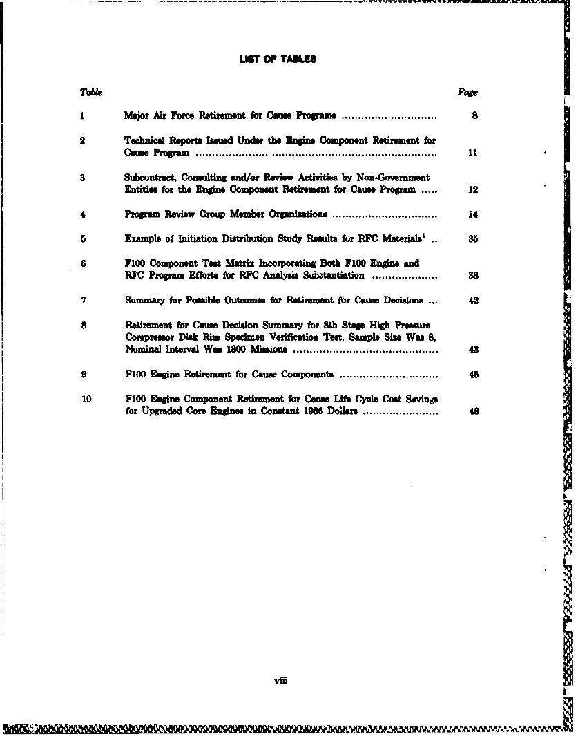
1 Total Fatigue Life Segmented Into Stages of Crack Development,Subcritical Growth and Final Fracture .......................................... 4
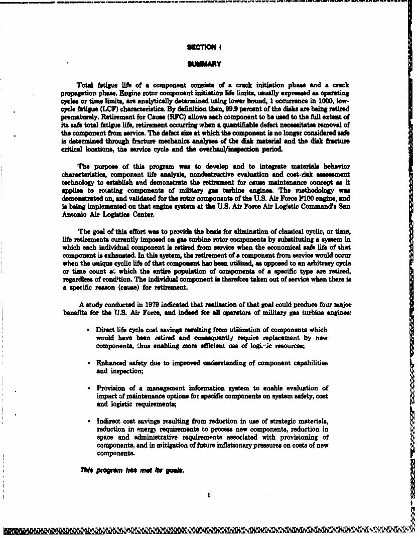
2 Historical Life Limit Methodology Precluded Use of All Available Lifein a Pop ulation of Miks ............................................................ 4
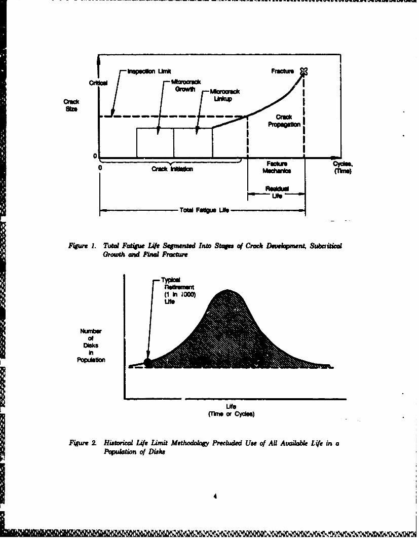
3 Many of These Disks Retired frum Service Have Usable LifeRema.........n....ng...................................................
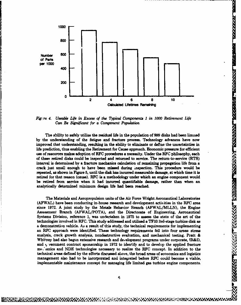
4 Useable Life in Excess of the Typical Components I in "0ORetirement Life Can Be Significant for a Component Population ....... 6
5 The Retirement for Cause Procedure Involves Inspection and Return-to-Service Until a Quantifiable Defect Is Found, Resulting inRetirement ............................................................................... 7
6 Program Phase and Major Task Structure With Summary of Resultsand Purpo es ......................................................................... 9
7 Functional Operation of the Engine Retirement for Cause Program .... 13
8 The F100 Turbofan Engine Which Powers the F-15 and F-16 Aircraft 17
9 Modular Configuration of the F100 Engine ................................... 18
10 F100-PW100/200 Force Structural Maintenance Plan Scheduled DepotVisit Rhythm ................................... 22
11 Propagation Margin, (PM), Defines the Relationship Between CwackPropagation Life and Return-to-Service Interval. This ExampleIllustrates a Propagation margin of Two ....................................... 24
12 Propagation Margin Is Determined from an Economic Balance BetweenHigh Cost of Failure and Cumulative Cost of FrequentInspection/Overhaul .................................................................. 25
13 Retirement for Cause Procedure Flow Chart .................................. 26
14 F100-PW100B/200B 7th-Stage, High-Pressure Comp.essor DiskProbabilistic Life Analysis ........................................................ 29
15 Variability In Crack Propagation Rate Is Defined By a Log NormalProbability Distribution ............................................................. 30
16 Existing Predictive Tools Adequately Predict Crack Growth from aVariety of Multiple Crack Initiations in a Typical Component StressR iser ..................................................................................... 31
vi
17 Typical Crack Growth Rate (da/dN) Stress Intensity Rang. (AK)Curve. Significat Portion of Life Is in the Formerly EtaoaeRegion ........................................... 33
18 Schematic Depicting LCF and LCF-Creep-Dweil Loading Scheame With(Lower) and Without (Upper) Sueimposed High Frequency Vibratory
*Loading .................................................................. 36
19 Predicted Crack Growth vemnu Actual Data for 7th-StageAirseu/Specer. Note Log Scale ........................... 39
20 Generic Specimen/Suboomponent Types Used to Verii* the ITJCP~rocess .......................................... 41
21 Actual Vernua Predicted Remaining Life for a Specimen VerificationTest Simulating the 8th-Stags High-Compressor Disk Rim, WaspaloyMaterial, eo00F Mission cycle ............................................ 42
22 Schematic of the F100 Life Cycle Cost Model Used to Evaluate RFC. 47
23 Propagation Margin Versus LCC for F100 Fan Drive Turbine Module . 49
vii
TOW LIST OF TAULPOP
1 Major Air Force Retirement for Cause Program s ............... a
2 Technical Reports Issued. Under the Engine Component Retirement forCasPrga u se........... .......o g r am................ 11
3 Subcontract, Consulting and/r Review Activities by Non-GovernmentEntfitie for the Engine Component Retirement for Cause Program ... 12
4 Program Review Group Member Organizations,........................... 14
5 Example of Initiation Distribution Study Results fur RFC Materials' * 35
6 F100 Component Test Matrix Incorporating Both F100 Engin andRFC Program Efforts for RFC Analysis Su~batantiation .................. 38
7 Summary for Possible Outcomes for Retirement for Cause Decisions .. 42
8 Retirment for Cause Decison Summary for 8th Stage High PressureCompressor Disk Rim Specimen Verification Test. Sample Size Was 8~,Nominal Interval Was 1800 Missions..................................... 43
9 F100 Engine Retirement for Cause Components ................... ...... 45
10 F100 Engine Component Retirement for Cause Life Cycle Cost Savinpa
for Upgraded Core Engines in Constant 1986 DoI ar ................... 48
viii
11,14,11Ki
ECTON I
IMM Y
Total fatigue life of a component consists of a crack initiation phase and a crackpropagation phase. Engine rotor component initiation life limits, usualy expressed as operatingcycles or time limits, are analytically determined using lower bound, I occurrence in 1000, low-cycle fatigue (LCF) characteristics. By definition then, 99.9 percent of the disks are being retiredprematurely. Retirement for Cause (RFC) allows each component to be used to the full extent ofits safe total fatigue life, retirement occurring when a quantifiable defect necessitates removal ofthe component from service. The defect size at which the component is no longer considered safeis determined through fracture mechanics analyses of the disk material and the disk fracturecritical locations, the service cycle and the overhaul/inspection period.
The purpose of this program was to develop and to integmte materials behaviorcharacteristics, component life analysis, nondestructive evaluation and cost-risk assessmenttechnology to establith and demonstrate the retirement for cause maintenance concept as itapplies to rotating components of military gas turbine engines. The muethodology wasdemonstrated on, and validated for the rotor components of the U.S. Air Force F100 engine, andis being implemented on that engine system at the U.S. Air Force Air Log.stic Command'. SanAntonio Air Logistics Center.
The goal of this effort was to provide the basis for elimination of classical cyclic, or time,life retirements currently imposed on gas turbine rotor components by substituting a system inwhich each individual component is retired from service when the economical safe life of thatcomponent is exhausted. In this system, the retirement of a component from service would occurwhen the unique cyclic life of that component hao been utilized, as opposed to an arbitrary cycleor time count aW which the entire population of components of a specific type are retired,regardless of cond&tion. The individual component is therefore taken out of service when there isa specific reason (cause) for retirement.
A study conducted in 1979 indicated that realization of that goal could produce four majorbenefits for the U.S. Air Force, and indeed for all operators of military gas turbine engines:
Direct life cycle cost savings resulting from utiiization of components whichwould have been retired and consequently require replacement by newcomponents, thus enabling more efficient use of logp,1c resources;
• Enhanced safety due to improved understanding of component capabilitiesand inspection;
Provision of a management information system to enable evaluation ofimpact cof maintenance options for specific components on system safety, costand logistic requirements;
Indirect cost savings rcsulting from reduction in use of strategic materials,reduction in energy requirements to process new components, reduction inspace and administrative requirements associated with provisioning ofcomponents, and in mitigation of future inflationary pressures on costs of newcomponents.
This progm ha met goas.

The Retirement for Cause maintenance concept is presently implemented on USA" F100rotor components it the San Antonio Air Losics Center in conjunction with the FI00 coreupgrade program. A total of 28 fan, compressor, and low-pressure turbine rotor components willbe managed under this philosophy. The F100 engine overhaul manuals (Techdical Orders) havebeen revised to eliminate classical time to compliance (retirement) limits for those componients,and incorporate RFC.
As a direct result of RFC, life cycle cost savings of $966 million are projected for the USAFF100-PW-100/200 engine systems over the period 1986 to 2006. An additional $656 millionsavings for which RFC is partially responebe (appi-mimately 46 percent) also accrue from laborand maintenance fuel savings due to extension of the maintenance larval for the upgradedF100 core engine. Thew savings represent the highest return-over $1.2 Billion uf any technologyeffort to date in the history of the Air Force Materials Laboratory (Air Force WrightAeronautical Laboratories).
The technology and procedures developed under this program are generic. While the USAFFIO0 engine was used as the demonstration vehicle, and the concept was validated for thatengine, the USA? TFSO engine was also reviewed. The technical basis has been established suchthat the procedure can be used on any gas turbine engine. The technical basis for probabilisticlife analyses has also been established, and has been accepted. In addition, a number of thetechnical elements of tie Engine Structua Integrity Program (ENSIP) were validated. Becauseof thsen activities, it is anticipated that Retirement for Cause will become the standard USAFprocedure for logistics management of the life limited components of all future engines.
A mejor factor in the success of this progrm in taking Retirement for Cause from a conceptto reality was the high level of coordination and teamwork maintained among the Governmentand industry orF-a--,dons involved. From the inception of the program, all USAF and otherGovernment organizations concerned with the development, operation and maintenance of gasturbine engines, and specifically the F100 engine, provided support, guidance, and managementdirection to the program. All corresponding Pratt and Whitney organizations were also involvedin the performance of this effort, as we!! as its subcontractors, consultants and other USAFcontractors. The primary vehicles for this interaction and coordination were executive, steeringand working groups which met repularly during the seven year period of the program. Thesuccess of the program validates that program management approach.
2~R~ m ~ mun~mt ai E,. m. ~ .~ . a - - - --.- - - - - - - - - - - - - - --

SECTION N
1. SAICGROWQO
Hist0rically, methods used for predicting the life of gat turbine engine rotor componentshave reulted in a conservative estimate of useful life. Most rotor components are limited by low.cycle fatigue (LCF) generully expressed in terms of mission equivalency cycles or engineoperational hours. 'Then some predetermined life lizdt is reached, components are retired fromservice.
The fatigue procoes for a typical rotor component such as a disk can be visualized asillustrated in Figure 1. Total fatigue life consists of a crack initiation phase followed by growthand linkup of microcracks. The resulting macrocrack(s) would then propagate wubcritically untilthe combination of service load (stress) and crack sie exceeded the material fracture toughness.Catastrophic failure would ultimately result had not the component been retired from service. Topreclude such cataclysmic failurs disks have been typically retired at the time where I in 1000could be expected to have actually initiated a short fatigue crack (0.03 inch). By definition then,99.9 percent of the disks are bI retired prematurely. This results from the fact that all fatiguedata have inherent scatter. When considered with ether uncertainties in any dssign system, e.g.stress analysis error, mision variability, fabrication tolerances, temperature uncertainty, thefinal life prediction is made using worst case conditions for an occurrence rate of 1 in 1000. Whenplotted on a life distribution curve as shown in Figure 2, this corresponds to approximately a -8sigma lower bound. It is at this life that all fatigue life limited disks are removed from service.This procedure has succesfully prevented catastrophic in-service failures. However, in retiring1000 disks because one may crsck, the remaining crack initiation life of the 999 theoreticallygood disks, (shaded area in distribion curve of Figure 2,) is not used It has been documentedthat many of the M99 remaining retired disks have considerable useful residual life, as shown inFigures 3 and 4.
31jy
- ,-.---- - ,' - q wig -- - - W u-~ U- WUW*U UU WE
$Pi hu lat Lknh
crewriI
I f Ppqptko
I IAOI _____ I
TOM Faugus Life
F4%mr 1. Tota Fatigue Lift Segmented Into Stoge of Crack Davekmnt, SubcaudCGGrowth and Fumd alh
NumbsrOf
Disksin
(rmo Cycles)
Figure 2. Hiatoia L14. Limit Methodolog Preckuded Use of AU Available Life in a
4
--- ---- ---IwkI
tta
5 1
1000
800
Number 8OWof Partsper 1000
400
200
O -L2 4 6 8 10
Cal~attd Uftmes Remam
FWgure 4. Useable Life in Excess of the Typical Components I in 1000 Retirement LifeCan Be Significant for a Component Population
The ability to safely utilize the residual life in the population of 999 disks had been limitedby the understanding of the fatigue and fracture process. Technology advances have nowimproved that understanding, resulting in the ability to eliminate or define the uncertainties inlife prediction, thus enabling the Retirement for Cause approach. Economic pressure for efficientuse of resources makes adoption of RFC procedures a necessity. Under the RFC philosophy, eachof these retired disks could be inspected and returned to service. The return-to-service (RTS)interval is determined by a fracture mechanics calculation of remaining propagation life from acrack just small enough to have been missed during inspection. This procedure would berepeated, as shown in Figure 5, until the disk has incurred measurable damage, at which time it isretired for that reason (cause). RFC is a methodology under which an engine component wouldbe retired from service when it had incurred quantifiable damage, rather than when ananalytically detarmined minimum design life had been reached.
The Materials and Aeropropulsion units of the Air Force Wright Aeronautical Laboratories(AFWAL) have been conducting in-house research and development activitiee in the RFC areasince 1972. A joint study by the Metals Behavior Branch (AFWAL/MLLN), the EngineAssessment Branch (AFWAL/POTA), and the Directorate of Engineering, AeronauticalSystems Division, reference 1, was undertaken in 1975 to assess the state of the art of thetechnologies involved in RFC. This study addressed and utilized a TF33 3rd-stage turbine disk asa demonstration vehicle. As a result of this study, the technical requirements for implementingan RFC approach were identified. These technology requirements fell into four areas: stressanalysis, crack growth analysis, nondestructive evaluation, and mechanical testing. Pratt &Whitney had also begun extensive research and development programs under corporate, IR&D,and v,.' vernment contract sponsorship in 1972 to identify and to develop the applied fracturemi-Cianics and NDE technologies necessary to realize the RFC concept. In addition to thetechnical areas defined by the efforts discussed above, the broad areas of economics and logisticgmanagement also had to be incorporated and integrated before RFC could become a viable,implementable maintenance concept for managing life limited gas turbine engine components.
6

Fracture -
SI , / /,' / /"Crock ~
Length 9~ 4 Retire Disk
NDE ULnit o O O O
A Safe R'etum-to-Servioe Intervalslime"
fture 5. The Retiremnt for Cause Procedure Involves Inspection and Return-to-ServiceUntil a Quantifiable Defect Is Found, Resulting in Retirement
The culmination of these preliminary activities was a study conducted by P&W in 1979 and1380 under Defense Advanced Research Projects Agency (DARPA) and AFWAL sponsorshipentitled "Concept Definition: Retirement for Cause of F100 Rotor Components," reference 2.This program was the first to consolidate and focus these disciplines on a specific engine systemand to quantify the benefits and riskL invlved. The methodology and results of the studyprogram have been discussed at many workahops and symposiums, and published in severalarticles, references 3, 4, 5, and 6.
Upon completion of the initial Concept Definimtion Study, AFWAL/Materials Laboratoryestablished a major thrust in RFC with the goal of reducing the coucept to practice with firstsystem implementation to occur in 1986 on the F100 engine at the San Antonio Air LogisticsCenter (SAALC). P&W developed the probabilistic life analyses, integrated logistics/economicmethodology, and RFC procedure to support this implementation. The RFC methodology isgeneric, and has direct applicability to fatigue life limited components of all gas turbine engines.While this program concentraced upon the F-100 engine, the USAF TF30 engine system was alsostudied. The use of Retirement for Cause for a given engine application must be technicallyfeasible. However, other factors, including economic desirability and compatibility with forcemaintenance/logistic structures must also be evaluated. Therefore, benefits of RFC must beweighed against, or in combination with, alternative procedures for each specific applicationbefore an implementation decision is made.
2. THE USAF RETIREMENT FOR CAUSE THRUST
The Air Force Wright Aeronautical Laboratories (AFWAL) had conducted a number ofprecurscr technology activities prior to the inception of this program. In 1979, a Retirement forCause Technical Thrust Area was established within AFWAL with Dr. W.H. Reimann of theMaterials Laboratory as the Thrust Manager. An integrated development plan to reduce theRetirement for Cause concept to practice was istablished. The initial application, and vehicle forthe reduction to practice, was the F100 engine. The development plan coordinated the activitiesof various units within the Air Force Systems Command, Air Force Logistics Command, AirForce 'actical Air Command and other Air Force, Department of Defense, and government
7
agencies with those of the Air Force's contractor and consulting organizations. It also providedfor independent review and consultation throughout the entire effort to assure the appropria-teness, timeliness and efficiency of the activities.
In addition to the internal Air Forco activities, the four contracted technology programslisted in Table 1 were conducted. A number of other Department of Defense contracted programswere also reviewed for application and/or incorporation of their technical results into the RFCThrust Activities.
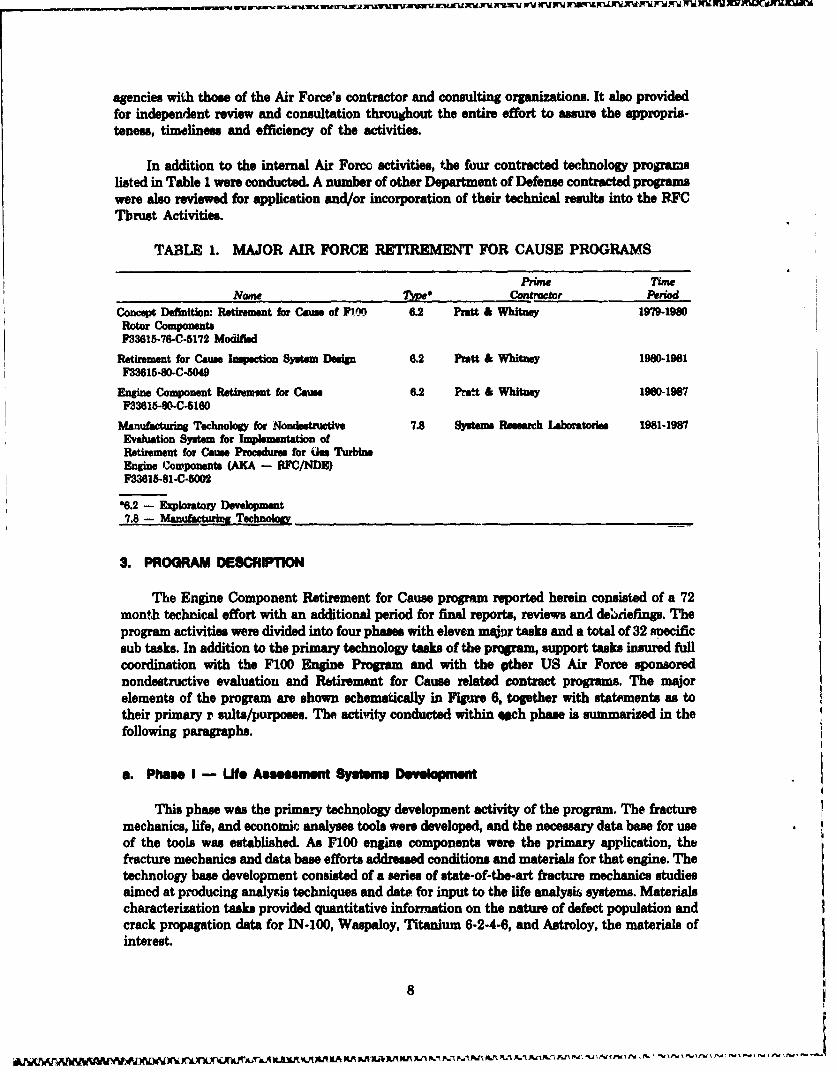
TABLE 1. MAJOR AIR FORCE RETIREMENT FOR CAUSE PROGRAMS
Prime TiowName 7Sme Contractor Period
Concept Definition: Retlrment for Cause of F1110 6.2 Pratt & Whitney 1979-1980Rotor ComponentsF33615-76-C-5172 Modified
Retirement for Cause Inspection System Design 6.2 Pratt & Whitney 1980-1981F33615-80-C-049
Engine Component Retirement for Cause 6.2 Pratt & Whitney 19W0-1987F33615-80-C-5160
Manufacturing Technology for Nondetructiv 7.8 Systems Rseasrch Laboratories 1981-1987Evaluation System for Implementation ofRetirement for Came Procedures for GOs TurbineEngine Cowponents (AKA - RFC/NDE)F33615-81-C-5002
06.2 - Exploratory Deelopment7.8 - Manufacturing Technology
3. PROGRAM DESCRIPTION
The Engine Component Retirement for Cause program reported herein consisted of a 72month technical effort with an additional period for final reports, reviews and de•defings. Theprogram activities were divided into four phases with eleven maj•r tasks and a total of 32 snecificsub tasks. In addition to the primary technology tasks of the prram, support tasks insured fullcoordination with the F100 Engine Program and with the other US Air Force sponsorednondestructive evaluation and Retirement for Cause related contract programs. The major
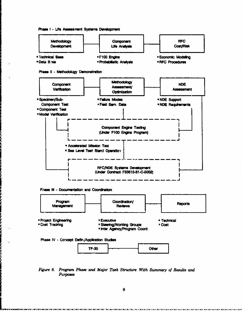
elements of the program are shown schematically in Figure 6, together with statements as totheir primary r sults/purposes. The activity conducted within ech phase is summarized in thefollowing paragraphs.
a. Phase I - Ut. Assessment System Development
This phase was the primary technology development activity of the program. The fracturemechanics, life, and economic analyses tools were developed, and the necessary data base for use "of the tools was established. As F100 engine components were the primary application, thefracture mechanics and data base efforts addressed conditions and materials for that engine. Thetechnology base development consisted of a series of state-of-the-art fracture mechanics studiesaimed at producing analysis techniques and date. for input to the life analysis systems. Materialscharacterization tasks provided quantitative information on the nature of defect population and
crack propagation data for IN-100, Waspaloy, Titanium 6-2-4-6, and Astroloy, the materials ofinterest.
8
PhM I - Life Aseessilet Systms Developrnent
MetJlodology Cornponwent RFCDevelopmen~t Ufle A yssCoot/Rlsk
0 YotwnicaI Bans *Fl00 Engine *Econani Modein* Datak B ýss a Probellstl Anelyals RFC Procechius
Phmv 11 - MeoUxMM Demonstniation
* SpeclrmsnSub- Faiure Modes *NDE SupportComnponent TMs 'Fiel Serv. Datae NDE Requiremnents
* Comnponent Test* Model Veriflcation
Component Engine Tastig(Under FiCO Engine Program)
"* Accelerted Mission Test"* Ses Leve Test 8tand Operafti [-1 ~RFC/NDE Systems DevelopmentI
(Under Contrat F33615-81-C-602L------------------------------
Phese III - Documentaton and Coordiniation
"* Project Engineerin 9 Executive * Technica"* Cost TracI~kn 0 Stesring/Workdng Groups 9 cost
9Inter AgenicyProgrern Coord.
Phms IV - Concept Defln./Appllcation Studies
Figure 6. Program Phase and Major Task Structure With Summary of Results and
9

A probabilistic life analysis technique (PLAT) had been previously defined, (Reference 2)and was developed. The information generated in the technology base studies was used to refinethis technique, or to prnvide inputs to the system. This probabilistic life analyses technique wasthen used in conjunction with thermal and stress analysis and nondestructive evaluiationinformation to perform life prediction calculations and sensitivity studies on specific F100 enginecomponents selected for Retirement-for-Cause. Results of these analyses were, in turn, employedin comparisons of cost versus risk and the life cycle cost calculations to establish strategies forimplementation of RFC, and to provide management information necessa:y for cost effectivemaintenance decisions.
b. Phsm - Methodology Doem-o sbon/Vadhtion
This phase demonstrated the tools developed in Phase I by laboratory testing of specimensand subcomponents to verify the statistical aspects of the predictive models. In addition, spin-rigtesting of turbine and compressor componeut assembies verified the fracture mechanics tools.No engine or rig testing was conducted in the program. However, an Accelerated Mission Test(AMT) of a full F100 engine with purposely flawed components was conducted in the F100Component Improvement Program. Technology activity in support of the AMT was provided,and the results were integrated into the RWV program. This test, equivalent to more than fouryears of service in the field, demonstrated fracture mechanicp/life analysis tools under realengine operating conditions, and verified the laboratory specimen and component test results.
In addition to the laboratory and engine test results, information was obtained from F-15and F-16 operating bases to confirm engine mission utilization, and from the San Antonio AirLogistic Center to assess field service performance of all F100 engine RFC CandidateComponents. This information and data was used to verify and optimize the methodology.
While no development of NDE systems was conducted under this program, NDE supportwas provided during the methodology demonstration. Requirements for inspection of thecandidate F100 RFC Components were defined, and were maintained current. This informationwas interacted with the Manufacturin& Technology for RFC/NDE Systems program conductedby Systems Research Laboratories. In turn, iWformation and results from that program wereutilized in both the Methodology Demonstration and Life Assessment System DevelopmentPhases of this program.
c. Phase III - Doumentaton and Coaedlhilon
This phase provided for program management, project engineering, program reviews, andworkshops, technical advisory services, and reports throughout the life of the program. It alsoprovided the vehicle for the intense coordination activities among the various units of theDepartment of Defense, other government agencies, and the industrial and academic organiza-tions involved. In addition to the normal contractual progress, status and final reports, specialinterim technical reports covering various aspects of the program were issued. These reports arelisted in Table 2. A very large number of informational briefings at all levels of both the UnitedStates and allied nation governments werc made, and aspects of the program presented atvarious technical conferences and symposiums.
10
ýN XIx" W%"W.w 'W v

TABLE 2. TECHNICAL REPORTS ISSUED UNDER THE ENGINE COMPONENTRETIREMENT FOR CAUSE PROGRAM
Tite Iderijicjion DatePosition PpXr. Vatdation of Retiment for Cause Mihbdo&f Via FR-149040 June 1981
Component Demmtration Testing
Application Study: Retiownt for Cause of USA" TF50 Engine AFWAL-TR-83--4020" April 1983Components
Thermal Mechianic Fatige Crack Growth AFWAL-TR44-4185 Much 1965
Engine Compmoent Rtirement for Cause Probabilistic Lif Analysis AFWAL-TR4-40750 June 1985Techni~n
Fractu Mechanies of Multipis Crck Initistions AFWAL-TR--4110 Oct 1985
*P~drt- lDistrfuion Domment
d. Phase IV - ConcepI Defdnluo SftuIes
This phase provided for studies and consultations to determine the technical and economicfeasibility of applying retirement for cause concepts to other propulsion systems. The mostextensive effort was conducted on the USAF TF30 gas turbine engine. This study also providedfor limited interaction with the Australian Department of Defense regarding the TF3O enginesoperated by the Royal Australian Air Force under the US-Australia Cooperative Research andDevelopment Arrangsement Number 79/70l.
The results of the study of application of retirement for cause to the USAF TF30 engineswere previously reported in detail and are only summarized in this report.
4. PROGRAM OPERATION
The technical and coordination activities of this program were accomplished in the timeperiod August 1980 through February 1987 by a project team assembled from the Engineeringand Government Products Divisions of Pratt and Whitney organized and directed by theRetirement for Cause Program Management Office (RFC/PMO) of the Materials Engineeringand Technology Branch, Engineering Divisio;. South. The program team also used a number ofother organizations, outside of the government and United Technologies, to provide subcontract,consulting, and/or indopendent review effort throughout the program. Major organiza-tions/individuals involved and the general area of their activities are listed in Table 3.
The program was organized and conducted using the phase-major task-subtask managerconcept wherein specific responsibilities were defined. With USAF approval, a Master Planningand Control Document was developed and maintained throughout the program, whichinterpreted the statement of work in terms of task descriptions, approaches, objectives, schedulesand resource allocations. This document was the primary tool for control and execution of theprogram.
11

TABLE 3. SUBCONTRACT, CONSULTING AND/OR REVIEW ACTIVITIES BYNON-GOVERNMENT ENTITIES FOR THE ENGINE COMPONENT RETIREMENT
FOR CAUSE PROGRAM
O • nInddJ 8 eSuht of Activ&yFailure Analysis Ameoates Probabiistic LifePalo Alto, Caifornia ethodoloy SportRockwell Internatonal Science Center 8stWtciMedologThotmande Os" CefifrniaDr. AY. Gradt, Jr. Multiple CrackPurdue University Inltllon/Growth
BehaviorDr. A.P. BAres Nondestructive EvaluationUniversity of Dayton Research Inst. Statistical AnaysiDr. J.H. Griffi Stree/Life PredictionCarnegem-•doa UniversityCenter for Nondestructive Bvuation Nondestructive EvaluationIrwa State Universty Technoloff
A major factor in the successful conduct of the program was the program review activities.These consisted of working groups, steering grou,•, and/or executive groups. Regular meetings ofthese groups were held to resolve technical problems, and to provide evaluation, critique andmanagement guidance by selected advisors from the government, industrial, (including P&Wmanagement), and academic communities. The purpose of the review activities was to focus theexpertise and attention of those organizations and individuals responsible for technologydevelopment, engine development, system operastion, and system maintenance upon thedevelopment of Retirement for Cause and its validation for, and application to, the F100 engine.Working groups addressed specific technical problem areas. The projet. group provided detailedpresentations of the work performed to the steering groups; the steering groups discussed thework and made recommendations to the executive group, comprised of senior managementpersonnel from the various organizations involved; the executive group review of the presnta-tions and recommendations resulted in and/or confirmed the technical direction, decisions andconclusions of the program. This nrathod of operation is shown in Figure 7. In addition to theprimary objective of providing technical and managerial guidance to the program, the programreview groups had four secondary objectives:
1. To ensure the program fully addressed all appropriate areas
2. To ensure continuing awareness and coordination throughout U.S. AirForce and appropriate government organizations
3. To define and assign specific responsibilities for execution of ancillaryactivities by government organizations
4. To assist in future aspixts of RFC activities as applicable.
The organizations and agencies represented on the steering and executive groups, andparticipating in the program reviews are listed in Table 4.
12

I I
Iii -t-- I J
13

TABLEI 4. P3OGRAM REVIEW GROUP MEMBER ORGANIZATIONS
Under Sucreery of Delnme forp Reseiarch and EgneIJDakm Advanced Rmeseach Pr Agecy Defts Selenose Office
United States Air Force -
Air force s e, lnB~ CenterAir Force Sydows Coummani
Aeronautical Sysdom DivisionTactical 110610 Propmm OfficFlight Sydowm Structures DivisionStructurmal Durabililty DivisionLola Hoonwring Divison
-abto Laghidim DivisonWright Aeraoautka Laboratories
Materials [iboratoryl-~qx o LaboraommFlght Dy~nodcs Laboratoy
Air Force Logistics Command:-Deput for Propulsion Mainterance (Mesmlqurtmr)San Antonio Air Lcgldice Centse
Directmrt, of Materials MaongermentDirectorate of Mainteniance
Oklahoma City Air Logitic CenterDiretorat of Materials ManagementDirectorate of Maintenanc
Tactical Air ConmmanDeputy for Maintenance/Prcpuson (Headquarter)
United States Army -
Aviation Technology DirectorateMaterials Technology Laboratry2
United States Navy -
Naval Air Systean CommandAir Vehicle Division. - ýucturesProduction Management Division/Applied Tlechnologyý
National Aeronutics and Space Administration
Liewis Research Centsr2
Federal Aviation AUthority2
Pratt & Whitney - United Technologies Corp@*stion
Engineering Division'Government Products Division
Systee Mosearch LabortOries, Inc.1
Notes I Progeram Management Responsibility
2 Coordination. Liaison or Atdvir Roie
14
5. RWlREMENT FOR CAUE A E TM BW STRUCTURAL MTERUTY PROOAM
There ia occasional conftsion regarding the relationship of Retirement for Camue (RFC)and the Engine Structural Integrity Progmrm (ENSIP). The ENSIP is defined by MilitaryStandard 1783 (USAF), and provides the bads for establishing the rquimnts, criteria, andmethods for the design of gas turbine engines and/or components. Included is the requikementfor damage tolerance in fracture critical parts, with fatigue crack initiation, (low cycle fatigue)life, and crack propagation life criteria. In addition, certain nondestructive inspection criteria arespecified.
Retirement for Cause is a component life management methodology. It may be applied toany life limited engine component, regardless of the criteria used in the design of thatcomponent. Retirement for Cause and ENSIP both draw from the same technology base, andboth involve similar component analyses. In many instances they ae Complimentar: i.e. damagetolerance concepts of ENSIP can be used in RFC, and probabilistic analysis techniquesdeveloped for RFC can be used in ENSIP. In fact, much of the technology bass of ENSIP haabeen demonstratd, and has been validated by the Air Force's RFC pogramns.
The major difference beteen the two programs is the point in time of application. TheEngine Structural Integrity Pregram is applied in the initial dsign and development phase of anengine program. Retirement for Cause is applied during the in-service, operational ,me, phase ofan engine system. The im of the ENSIP philosophy for an engine design will greatly facilitatethe use of RFC d ing its subsequent service life. As new engin systems entering the U.S. AirForce are being designed and developed under ENSIP criteria, RFC will emerge as the primarylife limited component maintenance procedure.
In summary, use of RFC naarally accrues with an ENSII designed engine; however, anENSIP engine deign is not required in order to qqy Retirement for Cause.
15
Wusn rlr tA.nar isr~a i-j. S 'nrt rsa n.~as .. S- flf. .. ~nSt fl .. -'- - - - - - - - - - -
SECTION U
THE P100 ENGINE
1. Im
The USAF F100 engine was chosen as the demonstration/validation vehicle for theRetirement for Cause (RCF) program. It is an augmented turbofan engine in the 25,000 poundthrust clas with a thrust to weight ratio approximately 8 to 1. The engine became operatonal inthe early 1970's in the F-15 aircraft at Luke Air Force Base, Arizona, and is currently in servicearound the world in the twin engine McDonnell Douglas built F-15, and the single engineGeneral Dynamics built F-16 fighter aircraft. There are in excess of 3200 of these engines in theUSAF opeational inventory.
Development and sustaining engineering activity is conducted in support of USAF F100engines under active Component Improvement Program (CIP) and Fngineering Assistance toProduction and Service (EAPS) programs managed by the San Antonio Air Logistics Center andthe Tactical Engines Program Office, ASD/YZ. The activities under the RCF program would beclosely moordinated, and in some case could be integrated, with the CIP and EAPS efforts. Theengine was chosen as the demonstration/validation vehicle to take advantage of thatrelationship. An additional reason for the selection of the F100 engine was that some of therotating components of that engine would reach their 1 in 1000 low-cycle fatigue (retirement)limits in the time period coinciding with the validation of the RFC methodology, thus facilitatingimplementation.
This has occurred the San Antonio Air Logistic Center implemented the RFC procedurefor selected F100 components in 1986 via proofing techniques and in 1986 via nondestructiveinspection techniques, and is continuing to phase additional F100 components into the process.
2. ENGIN DESCRITON
The F100 is an axial flow, low-bypas, high-compression ratio, twin-spool engine with anannular combustor and common flow augmentor. It has a three-stagse fan driven by a two-stag,low-pressure turbine, and a ten-stage high-pressure compressor driver by a two-stage, high-pressure turbine.
The engine is equipped with a variable convergent-divergent nozzle based upon thebalanced-beam concept. Nozzle area setting is a function of the engine control such that nearoptimum performance is provided at all operating conditions. The engine and its salient featuresare shown in Figure 8.
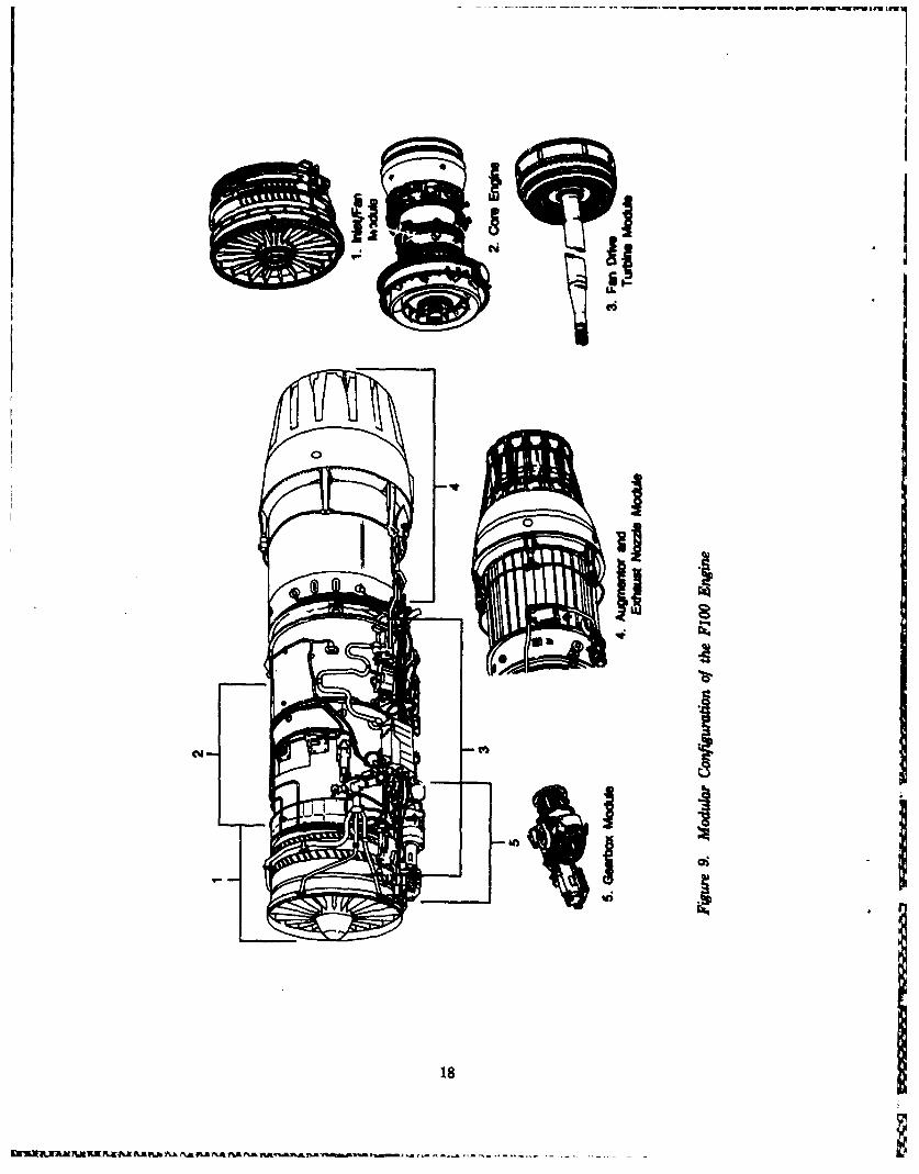
The engine consists of five major modules: fan, core (compressor, combustor, andcompressor-drive turbine), fan-drive turbine, augmentor and exhaust nozzle, and the gearbox.The modular configuration is shown in Figure 9. Each module is completely interchangeablefrom engine-to-engine at the base and intermediate maintenance level.
16

alll
17
- - - - - � �.. In,
ii1�
0 I
III
I
I
I18
�NIa&Ei�Ay�i �k #�* �* w�ANa � � --------. - - -
The modular qa•ppch was selected for the FI00 engine so parts smsociated aitherfunctionally or physically can be removed as units. Modular constcion has noultedd inincreased fledbility and reduction in the cost of maintabining the engine. Each module has itsown scheduled maintenance rhythm, and is returned to the San Antonio Air I Center foroverhaul/refutblbment independent from the other modules which constitute an engine.
The fan, coe, and fan drive turbine modules contain the disks and rim spacers/airsealsconsidered for RFC. The core consists of two major rotating assemblies, the compressor (high-pressu compressor and the compesmor drive turbine (high-pressure turbine, and emh of theseare considered separate items for the RFC maintenance concept
There are at the present time five model variations in the FI00 engine fimily, all derivedfrom the sam basic design and fitting within the sme airframe envelope. All versions aresimla in arrangement and concept, consist of the same five beas modules, and are maintainedon a modular basis. The existing model variations and a brief deserhptom are
1. FIOO-PWIO0 - Original version of the engine for twin engine applicationin F-16 aircraft
2. P100-P P120 - Original version of the engine for single engine applicationin F-16 aircraft
3. FIOO-PWI00 B/C - Engine containing an upgraded corn for F-16 aircraft.The letter suffix rofen to accessory configuration
4. F1OO-PW2WB - Engine containing an upgraded core for F-16 aircraft
5. FIOO-PW220 - Engine with an ENSIP designed core, often called anIncreased Life Core (IL) engine. Delivries of this engine began in 1986 Itis the current production engine, deliveries of F100-100/200 models havebeen phased out
6. P1OO-PWW9 - An increased performance version engine. This engine hassignificant differences in the rotor due to its different airflow. At thepresent time this engine is in the full-scale development phase withproduction anticipated in the the 1989 time hame.
The Retirement for Cause activities of this program were originally directed at the F100-PW100/200 models. When the decision was made to upgrade the core engine, Retirement forCause was incorporated as a part of the upgrade. It is anticipated that Retirement for Cause willalso be used when the F100-PW220 and PW229 versions attain sufficient operational time.
& P100 FORCE STRUCTURAL MANTENAC PLAN AD RETW NT FOR CAUSE IThe critical nature of the F100 engine to the Air Force's F-15 and F-16 weapons systems
made it important that the Air Force have the best possible visibil'ty of structural maintenanceneeds and component life limits for the engine.. Accordingly, an in-depth structural assessmentwas performed on this engine by a joint Air Force/P&W team. This effort, entitled "7100 EngineStructurl Durability and Damage Tolerance Assessment" (F.10) SAT), began in 1978, and Iconcluded in early 1962. The assessment activitin initiated by that effort ar continuing underthe F100 CIP and EAPS programs. These activiti•e were the source of many of the detailedcomponent analyses used in this program.
19
Ism. .'P %^AI %. p- i ^.-#I %JAnn P.~A &M~ &A &a &~A %-A S-M"".RkR
One of the primary objectives of durability and damage tolerance assessments is to definethe inspection requirements necessary to protect the structural safety throughout the anticipatedservice life. A second primary objective is to establish economical modification/repair andupgrade options for those components where they may be needed. This includes establishing thetechnical feasibility of the options, defining the validation requirements, estimating the probablecosts, and determining the post-mowfication/repair life limits and inspection requirements.
When the safety inspection requirements, and the repair/modification/upgrade require-ments are defined, they are incorporated into the force structural maintenance plan for theengine, assuming aircraft are flown to a specific usage/environment spectra. As usage maychange with time due to aircraft adaptation to new missions, tactics changes, or threat changes,continual review and upduting of engine usage spectra is conducted. As changes occur, thecomponent analyses and consequently the force structural maintenance plans are updated.During the time period of this program, two major revisions of the F100 force structuralmaintenance plans have occurred. The first revision resulted from a new mission analyse. for theF-16 aircraft, aka F-16 Reanalysis; the second revision resulted from the decision to upgrade thecore engine module of F100-PW100/200 engines.
The F100 structural assessment efforts are concerned with assuring that critical compo-nents safely reach their life limits, as opposed to safely exceeding the life limits, which is RFC.To assure this safety, the force structural maintenance plan defines component LCF limits andinspection intervals. Major depot maintenance actions are phased to correspond to theinspection intervals.
The maintenance actions and inspection intervals occur on a Total Accumulated Cycles(TAC) basis. Each installed engine is equipped with an events history recorder which monitorsengine rotational speed excursions and other operational parameters. These parameters are usedto calculate and count TAC's. The TAC count is applied to and tracked for each set of modulescomprising an engine. At a specified TAC count, with tolerance windows to allow foropportunistic maintenance, individual modules are removed, and are returned to the depot foroverhaul/inspection/refurbishment.
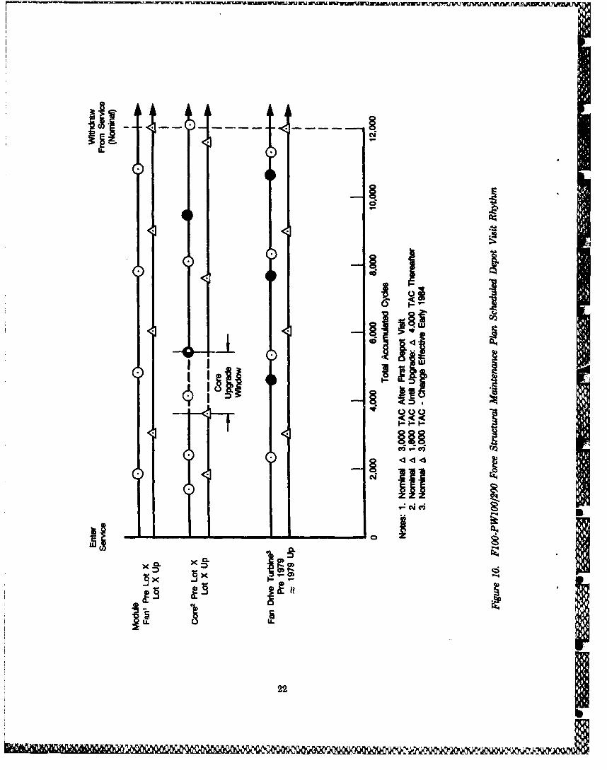
When the force structural maintenance plan was originally implemented, the fan and coremodules were on an 1800 TAC depot maintenance interval or rhythm, and the fan drive turbineon a 2300 TAC rhythm. This was equivalent to more than four years of field service. As a resultof CIP activities and the aforementioned F-16 reanalysis, ihe return-to-service interval for thefan and fan drive turbine was extended to 3000 TAC, however, the core remained on an 1800TAC interval.
In the early 1980's time frame, development activity aimed at improving durability andoperability produced a revised design of the core engine. This was an ENSIP design known as theIncreased Life Core (ILC). This core became the basis for the F100-PW220 model. It wasapparent that the benefits of the ILC were desirable for the F100-PW100/200 engine cores. Astudy conducted in 1984 indicated that retrofit of the existing F100-PW100/200 engines with anew ILC was not cost effective; however, several of the features of the ILC could be incorporatedthat would greatly enhance the existing fleet of F100-PW100/200 core engines.
The result of this activity was the definition of a core upgrade package. Major elements ofthis package include a new, damage-tolerant, high-pressure turbine, modifications to thediffuser/combustor, and modifications to the remote control variable vanes and airseals of thehigh-pressure compressor. The existing high-pressure compressor rotor is retained. The result ofthe core upgrade is an increase in the core engine module return-to-service interval from 1800 to
20

4000 TAC. The majority of core engines will be upgraded at their 3600 to 4100 TAC depot visit;the balance at the 5400 TAC depot visit.* To enable the HPC rotor to return-to-service for 4000TAC, the Retirement fok Cause procedure is utilized for many of the disks and airseals. This isbecausA many HPC components would reach their classical LCF retirement limits in the period3600 to 8100 TAC. The depot visit rhythm of the current force structural maintenance plan isshown schematically in Figure 10.
Retirement for Cause is applied to selected components at the module depot visit coincidentwith classical LCF retirement limits, or at the visit immediately prior to return-to-service for aninterval in which the limit would be reached. For the F100 engine, as for most engines, RFC is
compatible with force maintenance plan, thus requiring no revision of maintenance intervals,and in fact, presenting additional options for fleet life management decisions. The current F100force maintenance plan provides for no actions which would sustain field operations beyond12000 TAC. As this is equivalent to approximately 25 years of service, it is anticipated that FI00-PW100/200 engines would be phased out of the operational inventory by the end of that time.
Throughout the RFC program, close coordination was maintained between the RFCprogram group and the P&W and Air Force units responsible for the support of the F100 engineto assure that the development and implementation of the RFC procedure would not impact themaintenance rhythm. No adverse impact on weapon system readiness has occurred due toincorporation of RFC.
*Some early core engines-preproductionk lot X - had intermediate depot visits at 1300 and 2300 TAC. Thene core engineswere returned- to-service for 1800 TAC after the 2300 TAC depot visit. These engines would return to depot at 4100cycles, and would receive the core upgrade at that time. A similar situation exists due to extension in intervals for fan andfan drive turbine modules resulting in some irregularities in rhythm of the force structural maintenance plan.
21 ___________
rlw
Q 14 ýýIl 1-.1 6ý'Mu
Uus
22§
SECTION IV
RESUL"T
1. PROGRAM OBJECTIVE
The objective of this program was to provide a cost effective component manage-ment/maintenance methodology for fatigue life limited gas turbine engines systematized in aform that could be implemented at Air Force engine logistic centers. While generic in nature, thisprogram was directed towards the USAF F100 engine, specifically the various disks and airseals/spacers that comprise the prime rotor structure. The technical effort consists, of executinga series of tasks to obtain this objective by accomplishing the foilowing.
1. Development of a probebilistio. U6t &tnalysis system and the means of usingthat system to assess economic factors
2. Review, expansion and formatting of the fatigue and fracture mechanicstechnology base and its supporting materials characterization data toenable accurate residt al life analyses for the probibilistic le analysissystem
3. Demonstration of the validity of tho technology barn and the RFCmethodology by laboratory testing of specimens, subcomponents andcomponents, by actal engine testing of selected components, and bymonitoring the behavior of components in the USAF F1O0 operating fleet
4. Selection and analyses of specific F100 engine components
5. Economic analyses to document the benefits and risks associated with RFCof the selected F100 engine components
6. Interface and assistance in the imple~mentation of RFC for the F'iO0 engine,and for application to other engine systemE.
The results of the major activities are summarized in the following paragraphs. Detailedresults on a task by tuk basis axe documented in other Air Force Wright AeronauticalLaboratories technical reports issued under this contract.
2. MELHODOLOGY REVIEW
The general background and reasons for this program were discussed in Section U of thisreport. The methodology was originally &dimed in a precursor program conducted in 1979 to1980, Reference 2. That methodology did not change as a result of this program; some aspects ofit arc reviewed here to fix the context for reporting of the program results.
Referring to Figure 5, Section U, it can be seen that the RFC concept is based on fracturemechanics and nondestructive evaluation. Nondetrutive evaluation is used to ascertain thepresence or absence of defects in critical locations on a component. Fracture mechanics is used topredict the crack propagation life at every critical location from a defect size below the NDElimit of reliable crack detection. Given that the techiology exists to accurately do these twothings, a third factor impacts the decision making process: is RFC economically beneficial?
23

8. WSI -i Wrn
Fconomic benefits of RFC are a function of the return to service interval-crack propagetionlife relationship. If the return to service interval were short, relative to crack propagation life,high costs may be incurred due to frequent return of modules or engines for depot inspection/overhaul. If the return to service interval were long relative to crack propagation life, high costsmay be incurred due to in-ervice failure. The reýAtionahip between the return to service interval,and the crack propagation life, is defined as the propagation margin, and is illustated inFigre 11.
FAAe
Iftrva J-IT
I I
Cdes(N-
Fiure 11. Propagation Margin, (PM), Deffin the Rektionshp Between Crack PropagationLif and Return-to-Service IntevaL Thu Exanple Ilitrate a PmpagatwnMargin of Twvo
Applying a propagation margin assures safety in utilizing the remaining initiation life ineach component, recognizing that some uncertainties may still exist. This is done by determiningthe crack propagation life, Np, at every critical location on a component from a defect of a sizebarely small enough to be missed during inspection. The return to service interval, RTS, is thenestablished by conducting life cycle cost analyses to determine the most economical propagationmargin, PM, to apply to the shortest Np, thus RTS - Np/PM. In this context, propagationmargin is akin to a safety factor. Life cycle cost versus propagation margin is plotted for eachindividual component and combined to determine the most economical interval to return anengine or module for inspection. An example is shown in Figure 12.
b. The RFC Pcedre
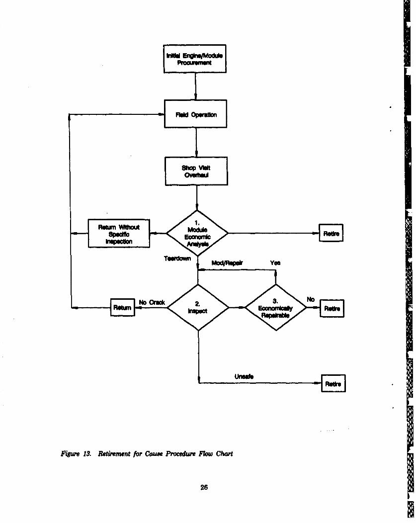
The RFC flow chart, Figur 13, illustrates a simplified view of how this maintenanceconcept is utilized. When an engine or module is scheduled for maintenance, an economicanalysis is performed on the engine or module, i.e., fan, compressor, high turbine, or low turbine,ids-itified as a participant of the RFC maintenance program. If the module has already been inservice for several inspection intervals, the probability of finding cracked parts may be great
24
MW WN

enough to mmke reinspection economically undesirable, and specific components of that moduleare retired without being inspected. This is determined by the economic analysis at decisionpoint one and is one of three possible decisions. An unscheduled engine removal, UER, may bringa module out of service that is more economical to return to service for the remainder of itsinspection interval than to inspect and release it for a new full interval, the second possibledecision at point one. The remaining choice at point one is to tear down the module and inspectthe parts. During inspection, there again are three possibilities, (decision point two). If no defectsare found, the part is returned to service. If the disk is found to be flawed, it is retired. The thirdchoice is to investigate modification or repair of a flawed part. An economically repairable partmay be repaired and returned to inspection, decision point three.
A~oo~kd94;Y*. 4.
Cost -I Op. ~Dik
L.• D- RI
Cyl . ,p...,.
' P. W . .,
- Co."
Cost~ ~ ~ ~ ~ ~ ~ ~ ~ ~~~~~s ofFiw n uuaieCs fFeun npcin o fehu
ý• I[• "'" :':'""a
c. MOO Engine Appicuilo
The RFC methodology discussed in the preceding paragrapbs presents a generic view of theprocess. In practice, return to service intervals may be based on more than inspectio~nconsiderations. In the case of the Fl00-PW-100/ 200 engines, maintenance rhythms were alreadyestablished, and propagation margin/life cycle cost evaluations were conducted corresponding tothose intervals. For future applications, however, a priori RTS analyses could be a major factorin establishing an initial force structural maintenance plan.
In following the RFC procedure shown in Figure 13, the module economic analyses, decision* point 1, was performed for the high pressure turbine unit of the core engine as part of the core
upgrade program. This analyses indicated that the probability of finding cracked parts in theHPT by M40 TAC was high, therefore, these units will be refired without inspection at thescheduled depot visit in the 3600 and 5400 TAC window. They will be replaced with the ILC(F100-PW220) HPT unit as part of the Core Upgrade Program. At the present time, fan, HPCand LPT modulesbypss point 1and godirectly topoint 2, humetion. As the USAJ F100 enginefleet ages, and engines are phased out of the inventory, the economic analysis otep will be
introduced for all modules.
25
•.;.:Frew• • .:::
mmui OPeratimma rv~m
I-
PFWM WMW .
MO"~
Tofm l yes
-- No Cro* 2.3.N
Fr13. Retirement for Cause Procedure Flow Chart
26
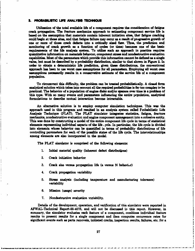
S. PROAtST�L M ANALYSM TRCHNIM
Utilization of the total available life of a component requires the consideration of fatiguecrack propagation. The fracture mechanics approach to estimating component service life isbased on the assumption that materials contain inherent initiation sites, that fatigue crackingcould begin at those sites, and that fatigue failure may occur as a result of proressive growth ofone or more of those crack defects into a critically sized fiew. Thu1, the prediction andmonitoring of crack growth as a function of cycles (or time) becomes one of the basicrequirements of the life analysis system. To utilime such an approach in practice requiresquantitative information on materials behavior, component stress and nondIstructive evaluationcapabilities. Most of the parameters which provide this information cannot be defined as a singlevalue, but must be described by a probability distribution, similar to that shown in Figure 2. Inorder to obtain a deterministic life prediction, given these distributions, the conventionalapproach has been to use worst case assumptions for all parametrs Employing all worst cseoassumptions necessarily results in a conservative estimate of the service life of a componentpopulation.
To circumvent this difficulty, the problem can be treated probablisticaly. A closed formanalytical solution which takes into account all the required probabilities is far too complex to bepractical. The behavior of a population of engine disks and/or spacers over time is a problem ofthis type. With so many events and parameters influencing the entire population, analyticalformulations to describe mutual interaction become intractable.
An alternative solution is to employ computer simulation techniques. This was theapproach used in this program and resulted in an analysis system called Probabilistic LifeAnalysis Technique (PLAT). The PLAT simulator integrates statistics, fatigue, fracture
mechanics, nondestructive evaluation and engine component management into a cohesive entity.This was done by constructing a model of the entire component life cycle in terms of statisticalelements representing individual aspecta of the life ,ycle. In particular, the life cycle is dividedinto elements whose behavior can be quantified in terms of probability distributions of lifecontrolling parameters for each of the possible states of the life cycle. The interrelationshipsamong elements are also incorporated in the model.
The PLAT simulator is comprised of the following elements:
1. Initial material quality (inherent defect distributions)
2. Crack initiation behavior
3. Crack size versus propagation life (a versus N behavivr)
4. Crack propagation variability
5. Stress analysis (including temperature and manufacturing tolerance)variability
6. Mission (usage) severity
7. Nondestructive evaluation variability.
Details of the development, operation, and verification of this simulator were reported inAFWAL-Technical Report-86-4075, and will not be discussed in this report. However, insummary, the simulator evaluates each feature of a component, combines individual featureresults to present results for a single component and then computes occurrence rates forsignificant events such as parts removals, initiated cracks, inspection results, failures, etc. for a
27
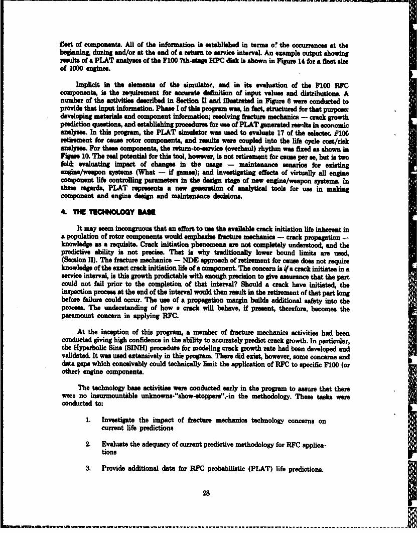
fleet of components. All of the information is established in terms of the occurrence@ at thebeginning, during and/or at the end of a return to service interval. An example output showingresults of a PLAT analyses of the F100 7th-stage HPC disk is shown in Figure 14 for a fleet sizeof 1000 engines.
Implicit in the elements of the simulator, and in its evaluation of the F100 RFCcomponents, is the reuirement for accurate definition of input values and distributions. Anumber of the activities described in Section II and illustrated in Figure 6 were conducted toprovide that input information. Phase I of this program was, in fact, structured for that purpose:developing materials and component information; resolving fracture mechanics - crack growthprediction questions, and establishing procedures for use of PLAT generated resdts in economicanalyses. In this program, the PLAT simulator was used to evaluate 17 of the selecteL P100retirement for cause rotor components, and results were coupled into the life cycle cost/riskanalyses. For these component., the return-to-service (overhaul) rhythm was fixed as shown inFigure 10. The real potential for this tool, however, is not retirement for cause per se, but is twofold. evaluating impact of changes in the usage - maintenance senarios for existingengine/weapon systems (What - if gumes); and investigating effects of virtually all enginecomponent life controlling parameters in the design stage of new engine/weapon systems. inthese regards, PLAT represents a new generation of analytical tools for use in makingcomponent and engine design and maintenance decisions.
4. THE TECHNOLOGY SAE
It may seem incongruous that an effort to use the available crack initiation life inherent ina population of rotor components would emphasize fracture mechanics - crack propagation -knowledge as a requisite. Crack initiation phenomena are not completely understood, and thepredictive ability is not precise. That is why traditionally lower bound limits are used,(Section II). The fracture mechanics - NDE approach of retirement for cause does not requireknowledge of the exact crack initiation life of a component. The concern is if a crack initiates in aservice interval, is this growth predictable with enough precision to give asurance that the partcould not fail prior to the completion of that interval? Should a crack have initiated, theinspection process at the end of the interval would then result in the retirement of that part longbefore failure could occur. The use of a propagation margin builds additional safety into theprocess. The understanding of how a crack will behave, if present, therefore, becomes theparamount concern in applying RFC.
At the inception of this program, a member of fracture mechanics activities had beenconducted giving high confidence in the ability to accurately predict crack growth. In particular,the Hyperbolic Sine (SINH) procedure for modeling crack growth rate had been developed andvalidated. It was used extensively in this program. There did exist, however, some concerns anddata gaps which conceivably could technically limit the application of RFC to specific F100 (orother) engine components.
The technology base activities were conducted early in the program to assure that therewere no insurmountAble unknowns-"show-stoppers",-in the methodology. These tasks wereconducted to:
1. Investigate the impact of fracture mechanics technology concerns oncurrent life predictions
2. Evaluate the adequacy of current predictive methodology for RFC applica-tions
3. Provide additional data for RFC probabilistic (PLAT) life predictions.
28
fl~~.. . . .. . . .. . . -~ -- -S -- - - --- - - - -- - - - -- - - - RSU nln n l.n e tb a t.f n m m m m m m m m m m m m
-Ra Solthl
L ft Foumtun ArmlyzedOkocwioMe at TAC INOWva
Evenvt I ,&*0 3,110 7,WO 111,8100
Nunderof DI~cs 4'0% 1,000 1.000 1,000N=Wumbenpected 1000 1,000 1000 1,000nspecuOn Enor 0 0.7 0.8 0.4
Replcod Disks 0 3 4 3RT8 Disks' 973 7157 540 249Rwomle DWuWa 27 243 40 1751Failkie 0 0 0 0Fibre Probelty 0 0 0.0002 0.0003
1. Returne to Servios After Inspection2. Rewoulced mud RTS. Rewos1k is Plumed Pert of a 4,000 Cycle Upgrad3. Probablty OwMInghterval Ending at Designatedl TAG4. Eng*"e Nomdwy R*ud at d* TAC. Rahits Shown for Inkomation Only
b. Remit of PLAT Aray11t - Occunuuoee we Per 1,000 Disks
Figure 14. FIOO-PW100B/200B 7th-Stage, High-Presawwe CoMpressor Disk Probabilistic LifeAnalysis
29
While generic in nature, the activities addressed the material. (IN 100, Titanium 6-2-4.6,Waspaloy and Astoloy) and conditions present in the FI00 engine, and built upon previous AirPorcm Material. Laboratories sponsored materials behavior progrm. Major results aresummarised in the following paragraphs, detailed approaches, support activities, data and resultsare included in other reports issued under this program.
a. Swdeost of IgSourM WMsh*
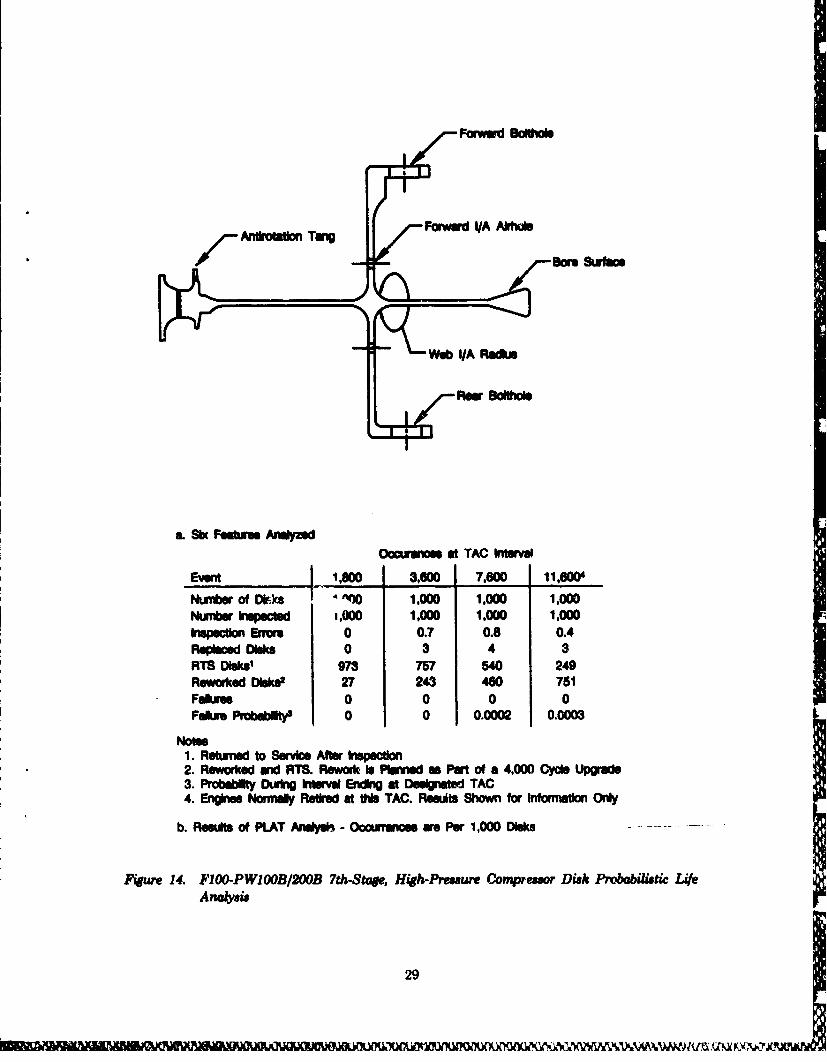
Among the variables contributing to the statistical nature of a probabilistic life analysissystem is the variability in the crack propagation rate data base. A crack growth curve (da/dN%rwsus AK) is not uniquely defined for a given set of operating conditions; rather, a statisticaldistribution describes the variability In crack growth rate about a curve representing meanbehavior.
Such inherent variability has numerous sources. Among these are variations in chemistry,%abrication, heat treatment, and microstructure. All such statistical sources are collectivelydescribed by the single distribution about the crack growth rate curve.
A methodology to define and assess the effects of this variability (scatter) in crackpropagation on residual life was developed in conjunction with work under AFWAL contractPF3615-80-C-5189, References 7 and 8.
It was found that the variability in crack propagation rate data may be described by a log-normal probability distribution. That is, for a given value of applied stress intensity range (AK),the corresponding crack growth rate (da/dN) follows a log-normal distribution about a meanvalue of da/dN, as shown in Figure 15. This variability results in a maximum/minimum crackpropagation life range of approximately 2, (as opposed to a crack initiation range of 10 orgreater), for the four materials of concern, and is accounted for by the addition of a Z(x) werm tothe Hyperbolic Sine model. This is a standard statistical technique, and is totally adequate forthis application.
Ca"g in Crack Size (da) 00Log. Increment of Cyee (M)of
Log. Strss hiteh RanW (a K)
Fiure 15. Variability In Crack Propagation Rate Is Defined By a Log Normal ProbabilityDistribution
30

b. Fnrmat M mn!e!anc of MulW* Crack a damt
Applied fr-ttire mechanics is predicated on a uni-puramnetrc relationship between thestats of the strme@ field surrowudis a crack w expressed by K, the stres intensity factor, andthe dynamic response of the crack do/dN. Currently available handbook solutions for K haveproven to be adequate for neary all singly occurring cracks. In real components, however, severalcracks may Initiate more or Is simulaesy within a stres riser, eg. bolthole, slot, thensynergistically propagate toward link-up, and subsequently behave as a single macrocrack. Onlyaftr link-up can theme be addressed in the conventional manner. The problem of multiple crackinitiation, link-up and propagation is nearly intractWe with analytical treatmevt, therefore anempirical approach was used. A variety of crack initiation confguations Figure 16, representingthe range of senarios which might occur in an engine component were tested. Existing lifeprediction tools, by modeling the resultant crack growth in two stages, were found to adequately(actually somewhat conservatively) predict the residual life of the four materials of concern forF100 component R]`C applications. This effort was completely documented in AFWALTechnical Report ('rR) 86-4110, Reference 9.
T O nr Noa CoMA m S U oMr M*i
SLNIMMmo Cru If ý
Fiue16. Existin# Predictive Tools Adequately Predict Crock Growth from a Variety ofMultiple Crock Initiations in a Typical Component Stress Riser
€. "Them l Mechanical F m CrW an)
It has been shown that thermal mechanical fatigue crack propagation is one of the primaryfailure mode. in cooled turbine airfoils, i.e. blades. This raised a concern as to the effect that thetemperature-load range conditions which exist near the rim of a turbine disk may have upon theadequacy of the crack growth predictions for potential flaws in that area of a disk. Traditiorally,these crack growth predictions are made using isothermal crack growth data at the temperaturecorresponding to the maximum loads expected to exist. In general, the predictions are accurate,or at least conservative. The purpose of this effort was to conduct an experimental program toassess the adequacy of using isothermal (constant temperature, load cycling), crack growth data at
for predictions of gas turbine disk life. This effort was not an exhaustive investigation of thermal
31

mechanical fracture mechanics, but focused upon materials and conditions typical of disks in anadvanced tactical fighter engine such as the F100.
The specific objectives were to evaluate any differences in crack growth rate in thematerials Astroloy and IN100 between isothermal and thermal mechanical cycling, and to assessthe impact these differances, if any, might have upon the implementation of the RFC concept forthese materials. Using the existing interpolative Hyperbolic Sine Model (SINH) the method ofevaluation was to compare crack growth rate (da/dN versus A) data generated under isothermalconditions with data for the same materials tested under in-phase (maximum tensile lood atmaximum temperature) and out-of-phase (maximum tensile load at minimum temperature)thermal mechanical cycling. It was found that the existing Hyperbolic Sine Model accuratelypredicted crack growth under TMF cycling when:- 1) isothermal data at the highest temperatureof the in-phase TMF cycle, and 2) isothermal data at the lowest temperature of the out-of-phaseTUF cycle, were used. Therefore, no significant difference in crack growth rate predictioncapability existed which would impect the application of RFC for the conditions found in disks orairseals/specers of the FIOD engine.
This effort was completely documented in AFWAL Technical Report, TR 84-4185,Reference 16•.
dl. Smull Crack/Stue Fiel Syneqism
Most experimental studies are made with large cracks to determine the fatigue crack growthrates and the threshold stress intensity on the basis of linear elastic fracture mechanics (LEFM)concepts. Very often, the fatigue I&e of a turbine component made of high yield strength materialis dominated by initiation and growth of very small cracks, which usually initiate at geometricstress risers such as holes and notches. Both crack-tip plasticity associated with localizedyielding and sine effects associated with the lack of a continuum at small-sise wsale may effect thecrack propagation behavior of small cracks.
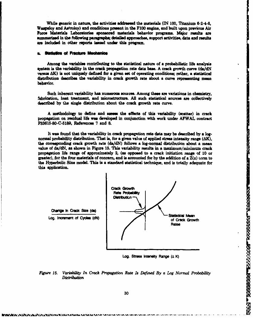
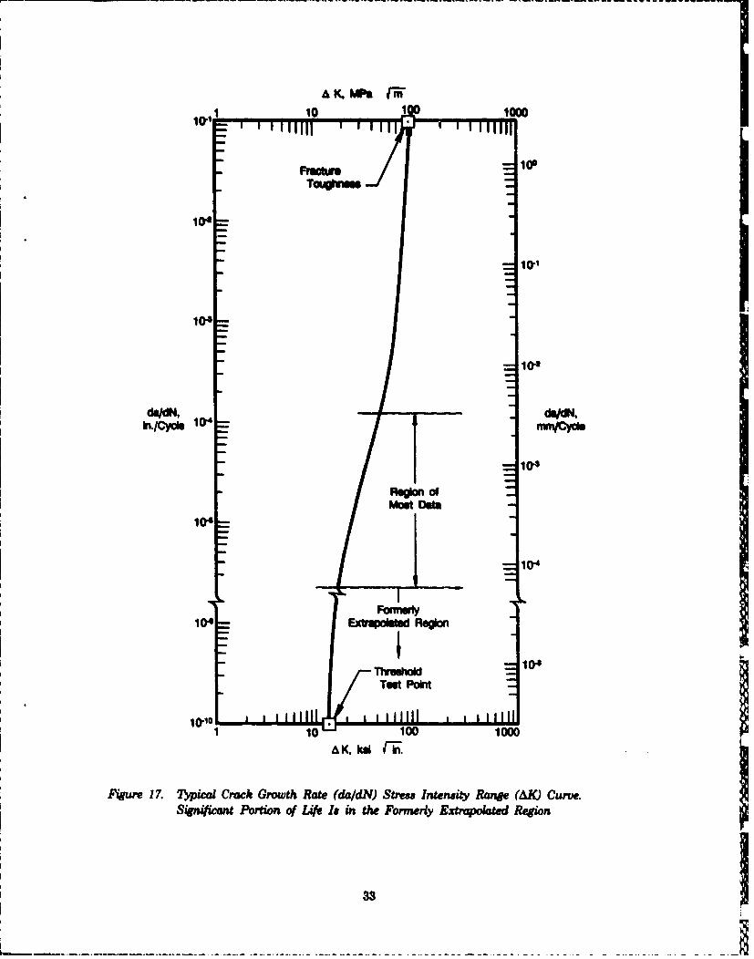
There is a unique strews intensity below which a crack will not grow. This is the thresholdstress intensity, Km. Normal procedure has been to extrapolate laree crack (>0.040 inch) datato very low growth rates to establish this point as shown in Figure 17. Some investigations havesuggested that small crack (0.006 inch) growth behavior, particularly in the near thresholdregaon, may be different, and that current linear elastic fractire mechanics methods are notapplicable in certain materials.
Testing methods were developed to enable precise determination of the threshold stressintensity and to establish crack growth rates for small cracks. This data was compared to longcrack data. Results indicate no significant differences in residual life predictions exist when usingsmall crack/threshold data as opposed to normal procedures for the materials of concern, and thebehavior of those materials in F100 components is adequately described by the LEFM techniquesused in RFC.
0. High-C le Fague/Low-C4yce Fugue (HCF/LCF) hiterctlon
Many gas turbine engine components are subjected not only to low-cycle fatigue and creep-fatigue type loading conditions, but to high-cycle or frequency, low amplitude vibratory fatigue(HFF) loads. This is particularly true in rotating components such as disk, and spacers wherethe effect of superimposed vibrational streesr associated with airfoil vibration could have anadverse influence on crack growth rate.
32
N~ V~VWWAA -Afi
10 low0
104
10.1
10-3
10.1
In./Cycle 10"IjMrjCY011
104
most Ofta
110-
1 04 E~xtrqdaimd Region
Test Point
S10 1 1000
A K, kl -in.
Fijure 17. 7ýpical Crack Growth Rate (da/dIJ) Stress Intensity Range (AK) Curve.Sijnificnt Portion a( Life Is in the Formerly Extrupokztcd Region
- - -
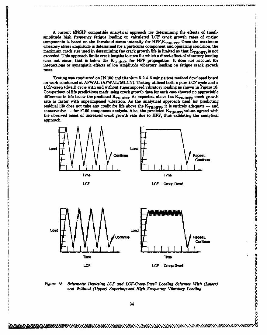
A current ENSIP compatible analytical approach for determining the effects of small-amplitude high frequency fatigue loading on calculated LCF crack growth rates of enginecomponents is based on the threshold stress intensity for HFF,KTH( I.). Once the maximumvibratory stress amplitude is determined for a particular component and operating condition, themaximum crack size used in determining the crack growth life is limited so that KTH(W) is notexceeded. This approach limits crack lengths to sizes for which a direct effect of vibratory loadingdoes not occur, that is below the KTH(14 for HFF propagation. It does not account forinteractions or synergistic effects of low amplitude vibratory loading on fatigue crack growthrates.
Testing was conducted on IN 100 and titanium 6-2-4-6 using a test method developed basedon work conducted at AFWAL (AFWAL/MLLN). Testing utilized both a pure LCF cycle and aLCF-creep (dwell) cycle with and without superimposed vibratory loading as shown in Figure 18.Cor--parison of life predictions made using crack growth data for each case showed no appreciabledifference in life below the predicted KTH(mW). As expected, above the KTH(HI, crack growthrate is faster with superimposed vibration. As the analytical approach used for predictingresidual life does not take any credit for life above the KrH(Yp), it is entirely adequate - andconservative - for F100 component analysis. Also, the predicted KTH(WI) values agreed withthe observed onset of increased crack growth rate due to HFF, thus validating the analyticalapproach.
Load LoadConti- Repeat,
Continue
LCF LCF - CreespDwel
Load LoadRpet
ConC Repeat,
LCF LCF - Creep-we
Figure 18. Schematic Depicting LCF and LCF-Creep-Dwell Loading Schemes With (Lower)and Without (Upper) Superimposed High Frequency Vibratory Loading
34
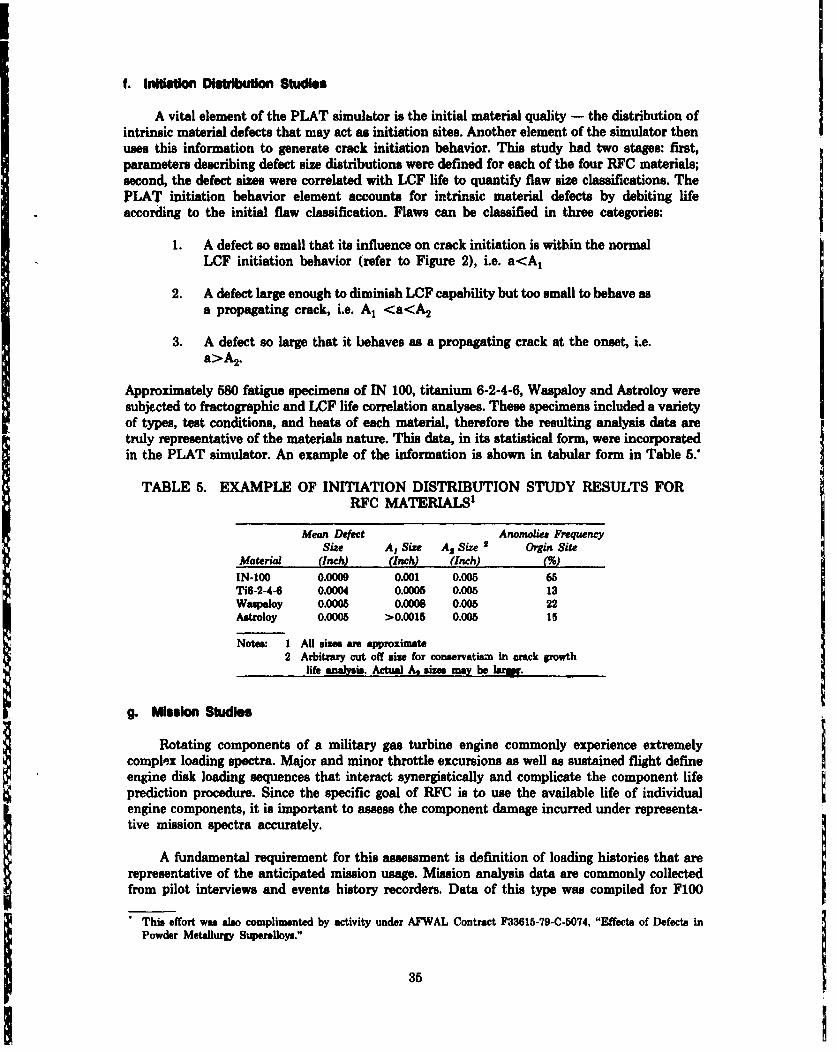
IIf. Initisuon Distribution Studies
A vital element of the PLAT simulhtor is the initial material quality - the distribution ofintrinsic material defects that may act as initiation sites. Another element of the simulator thenuses this information to generate crack initiation behavior. This study had two stages: first,parameters describing defect size distributions were defined for each of the four RFC materials;second, the defect sizes were correlated with LCF life to quantify flaw size classifications. ThePLAT initiation behavior element accounts for intrinsic material defects by debiting lifeaccording to the initial flaw classification. Flaws can be classified in three categories:
1. A defect so small that its influence on crack initiation is within the normalLCF initiation behavior (refer to Figure 2), i.e. a<A1
2. A defect large enough to diminish LCF capability but too small to behave asa propagating crack, i.e. A, <a<A2
3. A defect so large that it behaves as a propagating crack at the onset, i.e.a>A2.
Approximately 580 fatigue specimens of IN 100, titanium 6-2-4-6, Waspaloy and Astroloy weresubjected to fractographic and LCF life correlation analyses. These specimens included a varietyof types, test conditions, and heats of each material, therefore the resulting analysis data aretruly representative of the materials nature. This data, in its statistical form, were incorporatedin the PLAT simulator. An example of the information is shown in tabular form in Table 5."
TABLE 5. EXAMPLE OF INITIATION DISTRIBUTION STUDY RESULTS FORRFC MATERIALSi
Mean Defect Anomolies FrequencySize A, Size A2 Size 2 Orgin Site
Material (Inch) (Inch) (Inch) (%)
IN-100 0.0009 0.001 0.005 65Ti6-2-4-6 0.0004 0.0005 0.005 13Wapaloy 0.0005 0.0008 0.005 22Astroloy 0.0005 >0.0015 0.005 6s
Notes: 1 All sizes are approximate2 Arbitrary cut off size for conservatism in crack growth
life analysis. Actual At sizes may be humlr.
g. Mission Studies
Rotating components of a military gas turbine engine commonly experience extremely
complex loading spectra. Major and minor throttle excursions as well as sustained flight defineengine disk loading sequences that interact synergistically and complicate the component lifeprediction procedure. Since the specific goal of RFC is to use the available life of individualengine components, it is important to assess the component damage incurred under representa-tive mission spectra accurately.
A fundamental requirement for this assessment is definition of loading histories that arerepresentative of the anticipated mission usage. Mission analysis data are commonly collectedfrom pilot interviews and events history recorders. Data of this type was compiled for F100
This effort was also complimented by activity under AFWAL Contract F33615-79-C-5074, "Effects of Defects in
Powder Metallurgy Superalloys."
35

engine performance in F-15 aircraft and F-16 aircraft. While qirnilarities in usage exist for thesetwo aircraft, characterization of separate performance histories is warranted. Aside from theobvious benefits of accurately defining mission severity, recording the sequences of mission loadsis important. This is necessary to predict the effect of loading sequence on crack growth in enginecomponents that are candidates for RFC. In conjunction with F100 C( nponent ImprovementProgram activities, definition of mission profiles was obtained ar i maintained currertthroughout the program. This resulted in mission usage severity distril, t -,no development foruse in PLAT and in guidance for materials characterizations and for the development ofsynergistic crack growth models.
h. Mateftuls Chanectrzan~o
A large crack propagation data base existed for the materials used in the F100 RFCcomponents. Some conditions had not been investigated thoroughly and new conditions wereestablished as a result of the mission studies discussed previously. Approximately 90 crackgrowth rate tests and fractographic analyses were conducted to complete the data base for allconditions identified. In addition, test results from other activities in the technology base wereincorporated. Results of the materials characterizations were used to generate, or to refine thecrack growth models used for component life analyses. In total, over 200 crack growth tests wereconducted and mod~eled.
5. METHODOLOGY DEMONSTRATION AND VALIDATION
Implementation of the RFC methodology requires the systematic, coordinated applicationof several disciplines. Materials behavior, detailed and accurate component stress/strainanalyses, fracture mechanics probabilistic life analysis, and reliable NDE techniques arenecessary to evaluate the potentially critical locations of each component. Retirement for Causeintegrates these constituents to enable maximum utilization of component service life capability.However, before application to an active elugine system, the methodology must be demonstrated,qualified and validated. This was done for the RFC methodology, and for the F100 engine system.Laboratory specimen, subcomponent and component, and full-scale engine tests were conducted,and the status of components in the UJSAF F100 engine fleet was raonitored to assess and quaWi~the validity of the methodology.
The methodology demonstration and validation activities had four primary objectives:
1 . Provide component demonstration tests for selected components2. Substantiate statistical aspects of the RFC methodology3. Provide an RFC model demonstration4. Validate the process for implementation for the F100 engine system.
36
These objectives had to be accomplished within reasonable time and cost. Ideally numeroustests of each RFC component, either in an engine or under simulated engine conditions, would beubw-d for substantiation. However, the high costs associated with engine component cyclic testingprecluded performance of the required numb6r of tests for significant statistical substantiation.As specimen and subcomponent tests adequately represented critical variables, and could beeconomically tested in quantities necessary to substantiate statistical aspects of the RFC lifepredictions and methods, this approach was used. When coupled with selected laboratory andengine component tests, and the component field history from the large engine fleet, themethodology would be verified. The demonstration and validation process was based on thefollowing-
1. Selected component tests for substantiation of stress analyses, mean crackgrowth predictions, fracture path and other component geometric featurerelated vaelables
2. Specimen/subcomponent tests for evaluation of the statistical/probabilisticaspects of the RFC model, life predictions, and laboratory demonstration ofthe RFC model
3. Field data analyses for support and correlation of the above.
Nondestructive evaluttLion support was provided using the best available laboratorytechniques to minimize the uncertainty in NDE, and to provide maximum sensitivity forevaluating the accuracy of the life predictions and the contributors to life prediction uncertainty.Information obtained from the NDE evaluation was incorporated into AFWAL Contract F33615-81-C-5002, (Table 1) as were the RFC component inspection requirements.
The objectives of this effort were accomplished, thus facilitating implementation. Becauseof the successful demonstration/validation of the RFC methodology, the RFC process wasincorporated in the F100 Core Upgrade Program, resulting in accelerated implementation by theSan Antonio Air Logistic Center.
a. ComponeM Testing and Analysis
The primary purpose for component testing is to verify the component analysis and RFCmean predictions. Substantiating the component analysis includes assessment of the accuracy ofcomponent stress analyses and crack growth behavior for actual geometries. Substant' ition ofRFC mean predictions includes evaluation of stress analyses, mean predictions of crack growthrates, geometric feature cracking sequences, inspection intervals and variation in behavior fromone critical location to another within the same component. No actual engine testing wasconducted by this program. However, full support of the Aeronautical Systems Division TacticalFighter Engines Office, ASD/YZ, and the P&W F100 Organization enabled the RFC-PMO toincorporate and integrate RFC component demonstration activities with F100 ComponentImprovement Program activities, thus greatly enhancing the scope of the verification effort.
Specific RFC program sponsored component tests included laboratory spin tests undersimulated engine conditions of ten components of seven configurations. When coupled with theF100 Comrponent Improvement Program spin tests and Fracture Critical Parts EngineAccelerated Mission Test, a total of 19 RFC components were subjected to the detailedtest/analyses demonstration. In this manner, all RFC materials, generic geometries, and enginemodule/part types were represented by either engine or laboratory tests. The componentdemonAtration test matrix is shown in Table 6.
37

TABLE 6. F100 COMPONENT TEST MATRIX INCORPORATING BOTH F100ENGINE AND RFC PROGRAM EFFORT'S FOR RFC ANALYSIS SUBSTANTIATION
BnMW CIP RIYCModule Tent' Teat Tees AtWPWa Cam-polurnt
Pau 12 TiS.2-4- 2nd-Stags Disk and Hub12 WM-2-44 Srd-Sfje Disk12 T16-2-4- 2-3-Alrssa/Spseer
Compremor 1 2 Waspuloy 7th-Stag. Disk(HPC)
2 Waspaloy 8th-Stags Disk1 IN100 9th-Stags Disk
1 Walpaloy 12th-Stag. Disk1 IN100 13th-Stags Disk2 W~alpoy 7th-Stags Airasal/Spacer
I Waspaloy 10th-Stags Airaeal/Spaosr1 Astroloy 11th-Stags Airsealflpscer1 1 Astotloy 12th-Stags Airmasa/Spacsr
1 114100 13t-Stags Rotor Spacer/Cons
High-Prosaurs 1 14 IN100 1st-Stags DiskTurbine(HPT)
1 1 I100 2nd-Stags Disk1 14AeroWo 1st-Stags Blads Retainer (TOBI)1 1 INiCO 2nd-Stags Blade Retainer (1-2 Spacer)
Fan Drive 1 11N100 3rd-Stags DiskTurbine(LPT)
I 114100 4th-Stags Disk
Notes 1 1800 TAO miunium after flawing2 3600 TAO minimum after iflawing3 12,000 TAC minimum after flawing4 Continuation in laboratory of engine taut components
Except for the fan disks, the components tested had been previously used in engine service.However, all components contained multiple, nominally identical, limiting features. Through thecooperation of SAALC and P&W resident Air Force organizations, a high number of componentsobtained and tested had already exceeded their LOP retiremnent limit, and had been removed fromservice prior to use in this program.
Because RFC is concerned with component behavior if a flaw were present, all componentshad either natural or induced flaws prior to testing. Crack progression was measured duringperiodic inspections using surface replication; aspect ratios were determined from post testfractography.
The crack size observed from the testing was compared to the predicted crack size for eachfeature for at least one return to service intervaV Where more than one of each component wastested, and/or several nominally identical features, e.g. boltholes, were flawed, all data wascompared to the same prediction. An example, the 7th-stage HPC air seal/spacer, is shown inFigure 19.
Engine testing was conducted for 1800 TAC, the then RTS interval for the core module. With the upgrade, the core RTSwent to 4000 TAO. RFC sponsored spin touting was conducted to at losat 12,000 TAO.
38

II!+
1~C4
3(j
------------------------- -
More then 50 totep' features on the tested components were evaluated in this manner. Anumber of the features also had multiple examples. The actual and predicted mean crack growthwere in good agreement, and in many cams predicted growth rates were faster than actual growthrates (conservatism). This validated the fracture mechanics analysis and life predictionmethodology. In many cases, the actual cyclic life of flawed components greatly exceeded notonly the maximum return to service intervals but the total life expectancy of the F100 enginesystem! The 8th-stage high-pressure compressor disk was one example. Prior to use of RFC, thiscomponent would have been retired from service at approximately 5000 TAC. A retired 8th-stageHPC disk was obtained. This disk was subjected to an additional 6100 cycles before it waspurposely flawed. After flaws were introduced, the disk was installed into a 7th/Sth stackupwhich was spin cycled to failure, with periodic crack growth inspections. The disk accumulatedan additional 21,000 cycles before the 7th-disk in the stackup failed. This totals more than sixtimes the nominal retirment life, and almost three projected weapon system lives.
It is recognized that the limited number of component tests, .ducted does not provide fullstatistical validity. However, collectively, the results certainly bt- infidence in the analysisprocedures used for RFC of the selected FI00 engine components.
b. Speolmeis n/boom ponis Tesn ad Anelsis
The purpose of the specimen/subcomponent testing was two fold substantiation of lifeprediction and statistical methods with representative geometries and conditions, and provisionof a laboratory demonstration of the RFC process. To accomplish both of these purposes, asufficient number of tests for statistical evaluation is required.
As previously stated, the high cost and time required for engine component cyclic tests,even in a laboratory facility, precluded performing the number of tests needed for significantstatistical substantiation. Alternatively, sufficient quantities of specimens/subcomponents couldbe economically tested while adequately representing enough variables to provide substatiationfor statistical aspects. As a result, specimen/subcomponent configurations were designed,Figure 20, for the RFC component critical locations to be simulated.
The specimen/subcomponent test plan included all the relevant materials and genericgeometries. The tests also used appropriate mission cycles, with sufficient duplicate tests forstatistical evaluation, (approximately 110 total tests). The specimen/subcomponent test matrixwas sized to permit statistical evaluation of each variable at the lowest level, so that the cause ofprediction errors could be isolated to material, geometry or cyclic condition. The speci-men/subcomponent testing was carried out in accordance and simultaneously with thelaboratory demonstration of the RFC model.
Eight duplicate tests were conducted for each material, configuration and mission cycle.This number of duplicate tests was selected in conjunction with program consultants, (seeTable 3), to accomplish the objectives of the test, and was a sufficient sample size to statisticallydistinguish errors in mean life predictions for the sample if the actual results were more than33 percent too low or more then 50 percent too high (conservative) relative to the mean predictedlife. Differences in mean behavior of these magnitudes are statistically significant at a level of0.05, (95 percent). Similarly, differences in dispersion of the actual and predicted results are alsostatistically significant at the 95 percent confidence level if the observed standard deviation ofthe sample differs from the expected standard deviation by more than approximately 50 percent.
40
UW3~I ~ . mluk
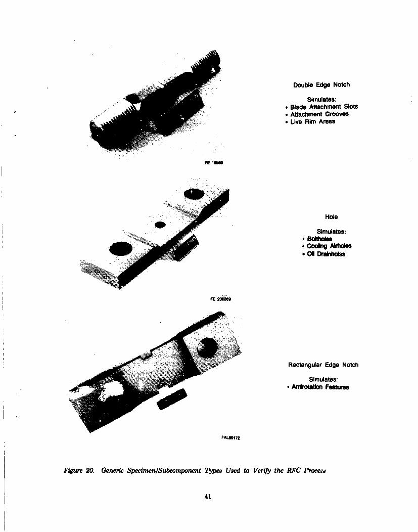
Double Edge Notch
Simulates:* Blade Attachment Slots* Attachment Grooves* Live Rim Areas
FE 1O9
Hole
Simulates:* BoltoesCoo AkO
(M Dririxo~a
FE 200iS
Rectangular Edge Notch
Simulates:*Aftiotmtion Features
F"1BS72
Figure 20. Generic Specimnen/Subcomponent Types Used to Verify the RFC Proceed
41
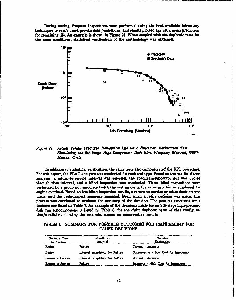
During testing, frequent inspections were performed using the best available laboratorytechniques to verify crack growth data )nredictions, and results plotted agasnst a mean predictionfor remaining life. An example is shown in Figure 21. When coupled with the duplicate tests forthe same conditions, statistical verification of the methodology was obtained.
100
0 Preoa0 Specime Data
crac
10-1OrctDepM
(Irchas)
r EM
El
r El10+ a illll * i illilll , ill
101 10 10aU 104
LWe Rm~ng (Msons)
Figure 21. Actual Venrus Predicted Remainim Li for a Specimner. Ver'ication TestSimulating the 8th-Stae High-Compreuor Disk Rim, Waipaloy Material, 600°FMission Cycle
In addition to statistical verification, the same teasts also demonstratmc! the RFC procedure.For this aspect, the PLAT ]nalyses was conducted for each test type. Based on the results of thatanalyses, a return-to-service interval was selected, the upecimen/subcomponent was cycledthrough that interval, and a blind inspection was conducted. These blind inspections wereperformed by a group not associated with the testing using the same procedures employed forengine overhaul. Based on the blind inspection results, a return-to-service or retire decision wasmade, and the cycle-inspect sequence repeated. Even when a retire decision was made, thisprocess was continued to evaluate the accuracy of the decision. The possible outcomes for adecision are listed in Table 7. An example of the decisions made for an 8th-stag high-pressuredisk rim subcomponent is listed in Table 8, for the eight duplicate tests of that configura-tion/condition, showing the accurate, somewhat conservative results.
TABLE 7. SUMMARY FOR POSSIBLE OUTCOMES FOR RE1IREMENT FORCAUSE DECISIONS
Decision Prior Resuko in Decisionto IntraaL interval Evoksation
Retd Failure Correct - Accurate
Retire Interval completed, No Failure Conservative - Low Cost for Inaccuracy
Return to Service Interval compltted, No Failure Correct - Accurate
Return to Service Failure Incorrect - Hlh Coat for Inaccura
42
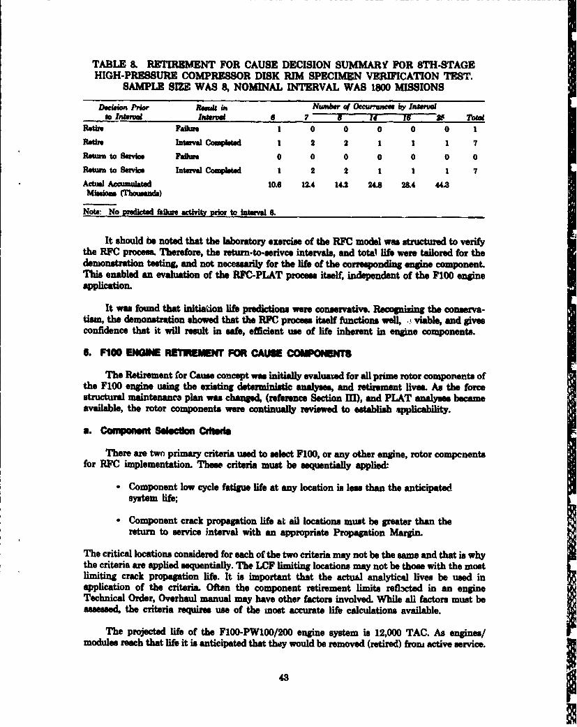
TABLE 8. RETIREMENT FOR CAUSE DECISION SUMMARY FOR 8TH-STAGEHIGH-PRESSURE COMPRESSOR DISK RIM SPECIMEN VERIFICATION TEST.
SAMPLE SIZE WAS 8, NOMINAL INTERVAL WAS 1800 MISSIONS
Dwition Prior i, ss in Number o Occurrorso by Inruai nto Intrval Intsel 6 7 8 Z4 if - Total
Retirn Failun 1 0 0 0 0 0 1tUN Intrvsal CompWtd 1 2 2 1 1 1 7
Retuv toSuvia Failure 0 0 0 0 0 0 0
Rturn to Serice InturvalComplnted 1 2 2 1 1 1 7Actual Accumulated 10.6 12.4 14.2 24.8 284 44.3
Note- No predicted Miure activity orior to interval .
It should be noted that the laboratory exercise of the RWC model was structured to verifythe RFC process. Therefore, the retumn-to-serivce intervals, and total life were tailored for thedemonstration testing, and not necessarily for the Uis of the corresponding e component.This enabled an evaluation of the RFC-PLAT process itself, independent of the F100 engineapplication.
It was found that initiation life predictions were conservative. Recognizing the conserva-tism, the demonstration showed that the RFC proces itself functions well, , viable, and givesconfidence that it will result in safe, efficient use of life inherent in engine components.
6. P100 ENOGI R EMENT FOR CAUSE COM MONET
The Retirement for Cause concept was initially evaluated for all prime rotor components ofthe F100 engine using the existing deterministic analyses, and retirement lives. As the forcestructural maintenanc. plan was changed, (reference Section III), and PLAT analyses becameavailable, the rotor components were continually reviewed to establish applicability.
a. Cmponent -I lecton Cdgsqnt
There are two primary criteria used to select F100, or any other engine, rotor compenentsfor RFC implementation. These criteria must be sequentially applied:-
- Component low cycle fatigue life at any location is leos than the anticipatedsystem life;
* Component crack propagation life at all locations must be greater than thereturn to service interval with an appropriate Propagation Margin.
The critical locations considered for each of the two criteria may not be the same and that is whythe criteria are applied sequentially. The LCF limiting locations may not be those with the mostlimiting crack propagation life. It is important that the actual analytical lives be used inapplication of the criteria. Often the component retirement limits refl3cted in an engineTechnical Order, Overhaul manual may have other factors involved. While all factors must beassessed, the criteria requires use of the most accurate life calculations available.
The projected life of the F100-PW100/200 engine system is 12,000 TAC. As engines/modules reach that life it is anticipated that they would be removed (retired) froni active service.
43

Thus in applying the first criteria any component with an LCF life, at any location, lees than12,000 TAC would be an RFC candidate.
After complete review, the Executive Group established additional guidelines for use of thePropagation Margin in the second criteria. Any component with a Propagation Margin of two orgreater would meet the criteria. If the Propagation Margin was lees than two, but greater thanone, appropriate PLAT and/or risk analyses would be conducted. Based on the risk assessment, afinal decision to include or exclude a component was made. The Propagation Margin calculationswere based on the return to service interval of the module containing the component i.e., fan,core or fan drive turbine, (reference Sections III and IV).
It is emphasized that both criteria must be applied in sequence. Failure to meet both criteriaremoves a component from consideration for RFC. For example, a component with a LCF lifegreater than 12,000 TAC would not be retired in the life of the system, therefore RFC is notapplicable and normal overhaul safety inspections would suffice. Conversely, for a componentwith a LCF life lees than 12,000 TAC, but a low propagation margin, RFC is also not applicable,assuming no change in return to service interval, and the component would be retired andreplaced at its LCF limit.
There are two additional factors that should also be considered in applying the selectioncriteria. If the cost of conducting the necessary component inspections exceeds the cost of a newreplacement component, it is not economically feasible to apply RFC. If replacement componentswere not available-at any cost-in the required time period, RFC may be neepseary regardless, inorder to maintain force readiness. These factors were also accounted for a cting F100 RFCcomponents.
b. Riresmnt for Caus Components
At the present time, 23 fan, high-pressure compressor and fan drive turbine disks and airseal/spacers are F100-PWl00BC/200B (upgraded core) RFC components. Should a core notreceive an upgrade, and be maintained on .n 1800 cycle rhythm as an F100-PW100/200 modelversion, an additional seven high-pressure compressor (HPC) and high-pressure turbine (HPT)components could be managed under the RFC process. As it is planned that all USAF F100-PW100/200 core engine modules will be upgraded, it is doubtful that RFC will ever be used forthese seven components. That option, however, exists.
The F100 Retirement for Cause Components are listed in Table 9, together with return toservice interval and material.
Currently, the upgraded core engine's 10-, 11- and 12th-stage HPC air seals and high-pressure turbine unit will not reach their life limits prior to removal of the F100-PWi00B-C/200B engines from active service, and therefore are not included in Table 9. Shouldcircumstances warrant extending the system life, RFC could be used. That option also exists. Ifsystem life extension were required, other F100 components, in addition to those discussed inthis paragraph, could also be managed with the RFC process.
c. Nondeetsic•re Evalusion Tehniques
Coupled with fracture mechanics analyses, reliable production oriented nondestructiveinspection techniques are required. The inspection requirements for each critical feature for eachRFC component were established. The appropriate NDE techniques to meet those requirementsare also listed in Table 9, and are of four types: proof test, eddy current, ultrasonic, and focusedfluorescent penetrant.
44
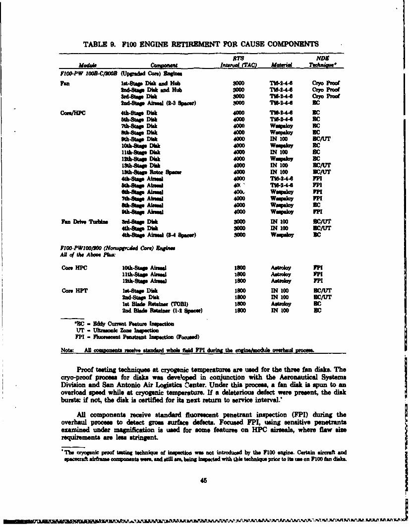
TABLE 9. F100 ENGINE RETIREMENT FOR CAUSE COMPONENTSR NDS
Module cony-wueag interva(TAC MaterWa TeehniouFIO-PW loo1.C/SOOB (Uppmdd Core) Sinu
PRO 1t-Sltp Disk and Hub 3000 T1"-&-44 Cio Proof2d-Sag Disk ad Hub 000 TW-2-44 CRYo Proobrd-Stas Disk 3000 7%-244 Cyo Proof2nd-4Sag Airse (2-3 Specs) 3000 7%2-4- BC
Com/HPC 4th•St Disk 40W0 116-244 2C8th-Stags Disk 40W TW1644 BClt.-tagS Dkk 4000 WMsIoy 1c8th-SBt Disk 4000 WaPquoy DCth-Stp Disk 4000 IN 100 BC/UT
10th-Sags Disk 40W0 eWaq"o DC11th-Stag Disk 4000 IN 100 DC12th-Stags Disk 4000 Wupaloy BC13th-Sag Disk 4000 IN 100 DC/UT1tb-Stap Rotor Spcr 40= IN 100 DC/UT4th-8Sa Aheal 4000 7W6244 FP18th-Sag Awal 40(1 IW-244 FF1Sb-ag- Aiea 400L Waqmoy VPH7th-StWs A 4000 Wavaay VP1
-thSag Aka 4000 Wow"o s DCth-Stag Aa 4000 Waqmlo FP1
Van Drie Tvunbin dSa Dik 8000 IN 100 3C/174th-Stap Disk 800 IN 1oo DC/1T74th&-Stap Aima (8-4 Opgwr) -000 Waqdor BC
F10-PWIOO/00 (Nonumvdd Core) RmlinaAU of t1e Abow Plm"
Core HPC 10th-Sts Ain@al 1300 Astoloy FPI11th-Stag Aluag 1800 Awtboby FPH12th-St AisMe 1800 Astroby FPI
CorN HPT 1st-Stae Disk 1800 IN 100 B3/UT2nd-Sta Disk 1800 IN 100 BC/UTlot Blad Retainer (TOBD) 1800 Astroly BC2nd Babs Reain (1-2 Specie) l80o IN 100 BC
•RC - 3ddy Curmt hature InMculonUT - tftrwmnik Zone Inqc•MuFP1 - Fwuoest Patrant ection (Focused)
Note. AM components reeive stmdard whole fl&d FP1 during the endiM6modul overhaul proom.
Proof testing techniques at cryogenic temperatures are used for the three fan disks. Thecryo-proof process for disks was developed in conjunction with the Aeronautical SystemsDivision and San Antonio Air Logisfics C:enter. Under this process, a fan disk is spun to anoverload speed while at cryogenic temperature. If a deleterious defect were present, the diskbursts if not, the disk is certified for its next return to service interval.
All components receive standard fluorescent penetrant inspection (FPI) during theoverhaul process to detect gross surface defects. Focused FPI, using sensitive penetrantsezamined under magnification is used for some features on HPC airseals, where flaw sizerequirements are less stringent.
"*The cryoanic proof ten technqu of inpection was not introduced by the F100 enginve. Certain aircraft andsacecraft airtmae cosponeat were, and stil are, ben in ctsd with this technique pror to it ue on FIOO fan disks
45
AAAJILA AfLA JA

Eddy current and ultrasonic technique. are used where critical surface and/or subsurface(internal volumetric defect) inspections m required. Specific inspection requirements wereestablished by this proaram for each component location or sons and interacted with SystemsResearch Laboratories Inc. (SRL), the developer and producer of the automated eddycurrent/ultraonic inspection system for RFC under USAF Contract F3615-81-C-5002.Continuous coordination between the P&W RFC group and SRL was maintained. The resultingadvanced state-of-the-art NDB system has been installed and is now operational doing RFCinspections at the San Antonio Air Logistics Center.
With RFC, (a with any safty oriented inspection), it is not the smallest flaw that can befound that may cause a problem, but the largest flaw that can be missed. To ensure adequacy ofthe RFC inspection processes, extensive reliability analyses were conducted. Results of themeanalyses, in the form of Probability of Detection (POD) distributions were then incorporated inthe PLAT component analyme. The RFC/NIDE system produced by SRL ham the highest in-production reliability of any inspection system produced yet. It is totally adequate forimplementation of RFC for F100 engine components. When coupled with Propagation Margin,this high POD minimies the effect of inspection uncertainty on component lMfe.
7. ECONOWMI ANALYSES
The underlying fracture mecaic/ife prediction and nondestructive evaluation technolo-g basis of RFC has been demonstrated/validated. There are no technical reasons why RFC cannot be used as a priori intention, as opposed to an after-the-fact necessity, for enginemaintenance. However, there must be a reason to use RFC. The primary premise for using RFCis that it will significantly reduce the cost of ownership of a engine system. Life Cycle Cost (LCC)savings are the means of measuring the reduction in cost of ownership.
A number of LCC models were evaluated for use in assesing RFC for the F100 enginesystem. In conjunction with the USAF Tactical Engines Programs Office, (ASD/YZ), a LCCmodel had been developed under the F100 Component Improvement Program called, appropri-ately, the F100 LCC Model. This model simulates fleet build-up/retirement/annualized costs andaccounts for all elements in the Joint Air Force/Industry Standard LCC Model criteria. Thismodel was selected for use in the RFC program. A major element of the model is the SupportCost Model. It is this aspect of LCC of a system that RFC impacts. The F100 LCC Model isshown schematically in Figure 22.
Initially, integration of the probabilistic life assessment (PLAT) and LCC models wasenvisioned. This approach was abandoned due to prohibitive computer size and computationaltime requirements. Consequently, slight modifications of the LCC program were made to acceptrequired information from PLAT and other sources as data sets. For the RFC componentsreceiving a probabilistic analyses, PLAT results were used. Conventional analysis data were usedfor the balance.
a. Ute Cydle Cost Swi~ngs
Life Cycle Cost analyses were conducted for two scenarios for the F100 upgraded core fleet:baseline, with components retired and replaced with new components at their LCF limits; and IRFC of the 23 components. The difference in the two analyses results is the LCC savings forRFC. In addition, as RFC makes possible a cost effective core engine upgrade, the cost savingsfor ths reduced number of core engine overhauls was also established.
46
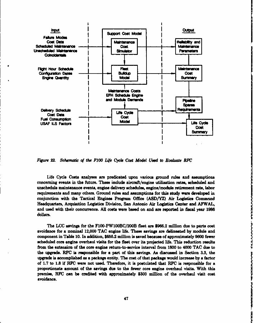
! I
I I
F pA Madecot odl ,_ II -odd
cost Do" MinhnwumR~ i
C - I
Figure 22. Schematic co the P00 Lfe Cl Cost Model Used to Evle RFC
Life Cycle t analyss are predicated upon various pound rule and assmptions
concerning events in the fuzture. These include aircraft/engine utilization rates, scheduled andunachedule maintenance events, engine delivery schedules, engine/modul, retirement rate, laborrequirements and many others. Ground rules and assumptions for this study were developed inconjunction with the Tactical Engine Program Office (ASD/YZ) Air Logistics Command
Headquarters, Acquisition Logistics Division, San Antonio Air Logistics Center and AFWAL,and used with their concurrence. All costs were based on and are reported in fiscal year 1986doilars.
The LCC savings for the F100-PW100BC/200B fleet are $966.2 million due to parts costavoidance for a nominal 12,000 TAC engine life. These savings are delineated by module andcomponent in Table 10. In addition, $666.2 million is saved because of approximately 9600 fewerscheduled core engine overhaul visits for the fleet over its projected life. This reduction resultsfrom the extension of the core engine return-to-service interval from 1800 to 4000 TAC due tothe upgre. RFC is responsible for a part of this sving . As disued in Section 3.3, the
upgrade is accomplished as a package entity. The cost of that package would increase by a factorof 1.7 to 1.8 if RFC were not used. Therefore, it is postulated that RFC is responsible for aproportionate amount of the saving. due to the fewer core engine overhaul visits. With thispremise, RFC can be credited with approximately $303 million of the overhaul visit costavoidance.
47
mW Mo"DwfwI
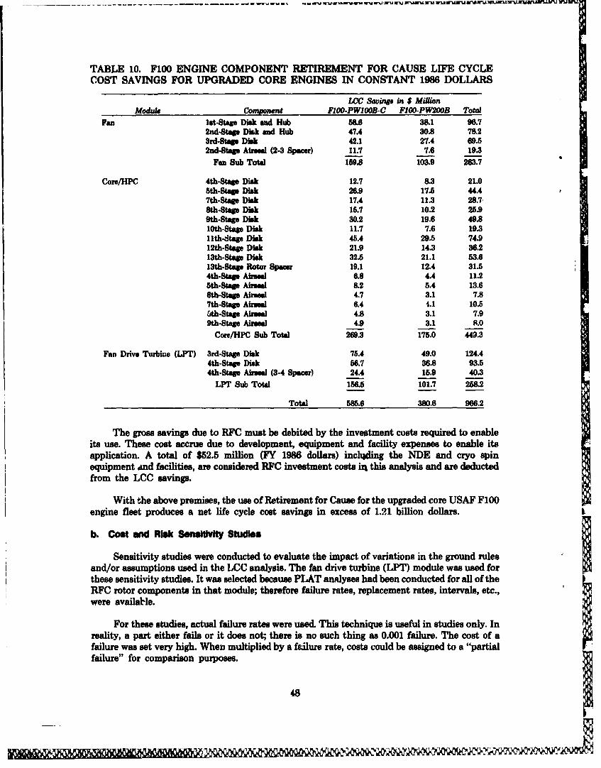
TABLE 10. F100 ENGINE COMPONENT RETIREMENT FOR CAUSE LIFE CYCLECOST SAVINGS FOR UPGRADED CORE ENGINES IN CONSTANT 1986 DOLLARS
C Swvings in $ MillionModule Coginnent FIOO-PWIOOB-C FIOO-PW200B Total
Fan let-Stap Disk and Hub 586 38.1 96.72nd-Stap Disk and Hub 47.4 30.8 78&23rd-Stap Disk 42.1 27.4 69.52nd-Sta Mrsl (2-3 Spacer) 11.7 7.6 19.3
Fan Sub Total 159.8 103.9 263.7
Core/HPC 4th-Stae Disk 12.7 8.3 21.05th-Stag Disk 26.9 17.5 44.47th-Stag Disk 17.4 11.3 28.7,8th-Stags Disk 15.7 10.2 25.99th-Stage Disk 30.2 19.6 49.810th-Stap Disk 11.7 7.6 19.3llth-Stage Disk 45.4 29.5 74.912th-Stagp Disk 21.9 14.3 36.213th-Stap Disk 32.5 21.1 53.613th-Stagp Rotor Spaew 19.1 12.4 31.54th-Stagp Mrseal 6.8 4.4 11.25th-Stag Airual 8.2 5.4 13.66th-Stap Airseal 4.7 3.1 7.87th-Stag Ainsal 6.4 4.1 10.5&th-Stags Ainseal 4.8 3.1 7.99th-Stags Airmal 4.9 3.1 8.0
Core/HPC Sub Total 269.3 175.0 449.3
Fan Drive Turbine (LPT) 3rd-Stage Disk 75.4 49.0 124.44th-Stasp Disk 56.7 36.8 93.54th-Stap Airmal (3-4 Spacer) 24.4 15.9 40.3
LPT Sub Total 156.5 101.7 258.2
Total 585.6 380.6 966.2
The gross savings due to RFC must be debited by the investment costs required to enableits use. These cost accrue due to development, equipment and facility expenses to enable itsapplication. A total of $52.5 million (FY 1986 dollars) inclhding the NDE and cryo spinequipment and facilities, are considered RFC investment costs in this analysis and are deductedfrom the LCC savings.
With the above premises, the use of Retirement for Cause for the upgraded core USAF F100engine fleet produces a net life cycle cost savings in excess of 1.21 billion dollars.
b. Cost and Risk Sensitivity Studies
Sensitivity studies were conducted to evaluate the impact of variations in the ground rulesand/or assumptions used in the LCC analysis. The fan drive turbine (LPT) module was used forthese sensitivity studies. It was selected because PLAT analyses had been conducted for all of theRFC rotor components in that module; therefore failure rates, replacement rates, intervals, etc.,were available.
For these studies, actual failure rates were used. This technique is useful in studies only. Inreality, a part either fails or it does not; there is no such thing as 0.001 failure. The cost of afailure was set very high. When multiplied by a f•alure rate, costs could be assigned to a "partialfailure" for comparison purposes.
48
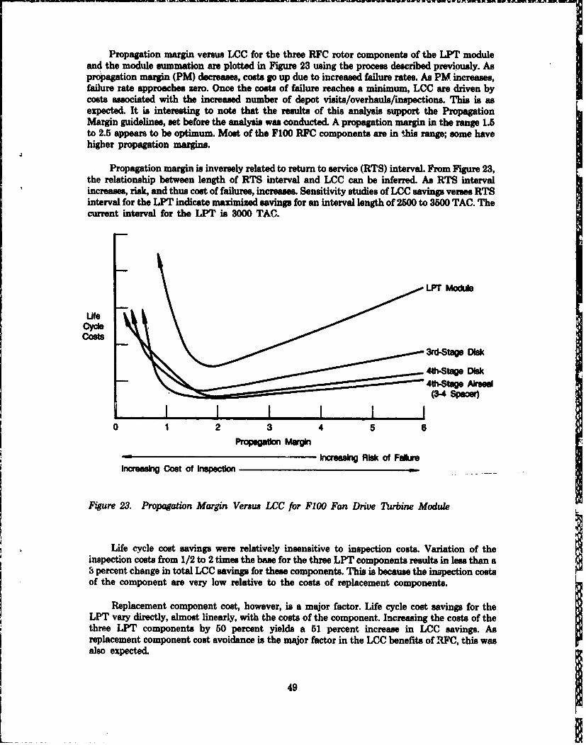
Propagation margin versus LCC for the three RFC rotor components of the LPT moduleand the module summation are plotted in Figure 23 using the process described previously. Aspropagation margin (PM) decreases, costs go up due to increased failure rates. As PM increases,failure rate approaches zero. Once the costs of failure reaches a minimum, LCC are driven bycosts associated with the increased number of depot visits/overhauls/imnpections. This is asexpected. It is interesting to note that the results of this analysis support the PropagationMargin guidelines, set before the analysis was conducted. A propagation margin in the range 1.5to 2.5 appears to be optimum. Most of the F100 RFC components are in this range; some havehigher propagation margins.
Propagation margin is inversely related to return to service (RTS) interval. From Figure 23,the relationship between length of RTS interval and LCC can be inferred. As RTS intervalincreases, risk, and thus cost of failures, increases. Sensitivity studies of LCC savings verses RTSinterval for the LPT indicate maximized savings for an interval length of 2500 to 3500 TAC. Thecurrent interval for the LPT is 3000 TAC.
LPT Mod~
Ufe
costs3rd-Stags DMk
4th-Stage k4th-tage Airusea
(3-4 -pas
0 1 2 3 4 5 6Propagaio Magi
Inoreasng Risk of Fab"Increasing Cost of Inspection
Figure 23. Propagation Margin Versus LCC for F100 Fan Drive Turbine Module
Life cycle cost savings were relatively insensitive to inspection costs. Variation of theinspection costs from 1/2 to 2 times the base for the three LPT components results in less than a3 percent change in total LCC savings for these components. This is because the inspection costsof the component are very low relative to the costs of replacement components.
Replacement component cost, however, is a major factor. Life cycle cost savings for theLPT vary directly, almost linearly, with the costs of the component. Increasing the costs of thethree LPT components by 50 percent yields a 51 percent increase in LCC savings. Asreplacement component cost avoidance is the major factor in the LCC benefits of ,FC, this wasalso expected.
49
A similar relationship exists between LCC savings and the number of LPT modulesmanaged undur RFC. Should the LPT modules of the FIOO-PW220 engines be included,(approximately 1500 additional) the savings increase from $258 million to $377 million.
Life cycle cost savings are sensitive to many factors. Only a few parameters were evaluatedherein, and then within the ground rules and asumptions initially established. Other weaponsystem factors, not directly related to the specific components evaluated, may have influencesthat mitigate these results.
8. APPUCATION TO OTHER ENGIES - THE TF30
The feasibility of applying a RFC maintenance approach to the rotor components of theUSAF TF30 engines was evaluated. Unlike the F100 engine, the TF30 is significantly advancedin life cycle. Therefore, in addition to determining the technical feasibility, the economicdesirability of performing RFC was asesmed in conjunction with other maintenance options. TheTF30-P3 and P100 engine models were shtdied in detail. Because of simularities in the rotorcomponents, the P7 and P9 models were included by extrapolation of P3 data and results.
Three scenaeioe were eialuated:.
1. Perform RFC on current engine components
2. Incorporate "full life" redesigned components in engines
3. Incorporate redesigned components and perform RFC on remaining eligiblecomponents.
The basis for comparison was the effect on projected life cycle costs of the engine. Thebaseline situation consisted of the current engines with continuation of the existing enginedesign and maintenance proceduis throughout the engine system projected service life. Theimpact of each senario on LCC was compared to the baseline to evaluate benefits. In addition tothese comparisons, sensitivities to fleet size, fleet uitilization life, and propagation margin weredetermined. It was found that applying RFC resulted in LCC savings for all TF30 engine models,but incorporation of redesigned components produced higher LCC savingp than use of RFC. Asexpected, LCC savings were maximized when RFC was applied to the redesigned engines.Extension of the weapon system retirement life also favored incorporation of redesignedcomponents.
This effort was completely documented in AFWAL Technical Report, TR 83-4020,Reference 11.
50
LlJ

WECiON V
CONCw-ON
Engine Component Retirement for Cause is technically valid and economically desirable.The benefits are so eifnificant that RFC was implemented for cGmponents of the F100 engine asthis technology contract program was being completed. It is anticipated that RFC will becomethe standard procedure for maintenance management of life-limited components of all utureUSAF gas turbine engiues, and potentially for any fatigue life-limited system.
In addition to the LCC savings, there are other, less tangible benefits. For the F100 enginealone, it is estimated that more than 3500 tons of strategic material use is avoided over the totalengine system life by not producing the quantities of spare parts that would have been requiredprior to RFC. In this regard, while not the primary objective, RFC evolves as one of the largest ofthe strategic material conservation efforts.
Another intangible benefit is the change in perception of and attitudes toward damagetolerance and probabilistic concepts that occurred over this programs duration. This, too, speakswell for future engine systems.
This program demonstrated that RFC is viable for the F100 engine. It is stronglyemphasized, however, that to use RFC for other engines, thorough knowledge and understandingof the materials behavior, component operating conditions, engine use, and logistics/maintenance system involved are required to avoid undesirable consequences.
51
REFMRENCES
1. Hill, R., W. Reimann, J. Ogg, A Retirement for Cause Study of an EngineTurbine Disk, AFWAL-TR-81-2094, November 1981.
2. Harris, J.A., Jr., D. L. Sims, C. G. Annis, Jr., Concept Definition:Retirement for Cause of FI00 Rotor Components, AFWAL-TR-80-4188,September 1980.
3. Annis, C. G., Jr., M. C. VanWanderham, J. A. Harris, Jr., D. Sims, "GasTurbine Engine Disk Retirement for Cause: An Application of FractureMechanics and NDE," Journal of Engineering for Power, Volume 103, No.1, January 1981.
4. Annis, C. G., Jr., J. S. Cargill, J. A. Harris, Jr., M. VanWanderham,"Engine Component Retirement for Cause: A NDE and Fracture Mechan-ics-Based Maintenance, Concept," Journal of Metals, July 1981.
5. Proceedings of the DARPA/AFWAL Review of Progress in QuantitativeNDE, AFWAL-TR-81-4080 pp 12-20, September, 1981.
6. Harris, J. A., Jr., C. Annis, Jr., M. VanWanderham, D. Sims, EngineComponent Retirement for Cause, AGARD-CP-317 "Maintenance in Ser-vice of High Temperature Parts" January 1982.
7. Yang, J. N., G. Salivar, C. G. Annis, Jr., Statistics of Crack Growth inEngine Materials, Vol 1 AFWAL-TR-82-4040.
7. Yang, J. N., G. Salivar, C. G. Annis, Jr. Statistics of Crack Growth in EngineMaterials, Vol U AFWAL-TR-82-4040.
9. Cowles, B. A., A. B. Thakker, G. E. King, Fracture Mechanics of MultipleCrack Initiations - An Application for Analysis of Gas Turbine EngineDisks, AFWAL-TR-85-4110, B. A. Cowles, A. B. Thakker, G. E. King,October 1985.
10. Wilson, D. A., J. R. Warren, Thermal Mechanical Fatigue Crack Growth -An Application for Fracture Mechanics Analysis of Gas Turbine EngineDiskxAFWAL-TR-84-4185, March 1985.
11. Harris, J. A., Jr., R. White, Application Study: Retirement for Cause ofUSAF TF3O Engine Components, AFWAL-TR-83-4020, April 1983.
52
amC