stationary integrated systems - bauer high pressure ... · bauer shall not be liable for...
TRANSCRIPT

Instruction Manual and Replacement Parts List
BAUER Compressors, Inc. Phone: (757) 855-60061328 Azalea Garden Road Fax: (757) 855-6224Norfolk, Virginia 23502-1944 www.bauercomp.com
October 22, 2009 1st Edition, Rev. 2 Chg. 2 MNL-0375© 2004 - 2009 Bauer Compressors, Inc.
Stationary Integrated SystemsHigh Pressure Breathing Air Compressor UnitsUNICUS III 20UNICUS III 26

UNICUS III
Page i 1st Edition, Rev. 2 Chg. 2
This information is believed to be accurate by Bauer Compressors, Inc., as of it’s date of publication, but Bauer offers NO WARRANTY regarding the accuracy, or continuing accuracy, of the information set forth herein. Bauer shall not be liable for inaccuracies in, or consequences resulting from, your use of this information. All information supplied is in connection with sales of Bauer’s products, and is thus subject to Bauer’s standard terms and conditions of sale. Bauer reserves the right to change this infor-mation and has no obligation to update these materials. This information is © 2004 - 2009 Bauer Com-pressors, Inc., and Bauer reserves to itself all rights to this publication. Bauer’s customers have no right to reproduce, rewrite, modify, license or permit anyone else’s use of this information, without the express written permission of Bauer Compressors, Inc.
^ WARNING
This Instruction Manual and Replacement Parts List contains safety information and instructions forthe UNICUS III High Pressure Breathing Air Compressor Units.You must read, understand and follow all safety precautions and instructions.
1st Edition
Rev Chg Date Notes Auth
0 0 Nov. 15, 2004 JD
0 1 Feb. 22, 2005 Added Idler Wrench and Leveling Feet JD
0 2 Mar. 8, 2005 Added Air Filter Indicator & Overrun Time JD
0 3 Sept. 22, 2005 Changed 3rd Stage Intermediate Separator to P/N 081798 JD
0 4 Nov. 3, 2006 Added CFSII Bottle Riser JD
0 5 Nov. 30, 2006 Changed P/N of Oil Pressure Gauge GAG-0006W to GAG-0042W JD
0 6 Mar. 29, 2007 Change to Separator P/N 079416 Life Span JD
0 7 Oct. 30, 2007 Update ACD Solenoid P/N AC DC JD
0 8 July 18, 2008 Added “After Cylinder Failure” Warning CLA
0 9 Sept. 9, 2008 Converted to Securus II SS
1 0 Nov. 18, 2008 Changed Drive Chapter and P5 Securus II section SS
2 0 July 29, 2009 Converted to Maple System & Siemens electric SS
2 1 Sept. 28, 2009 Fill Hose P/N’s SS
2 2 Oct. 22, 2009 Corrected Dryer Cartridge P/N SS

MNL-0375
October 22, 2009 Page ii
Table of Contents
CHAPTER 1: - - - - - - - - - - - - - - - - - - - - - INTRODUCTION
1.1 HOW TO USE THIS MANUAL......................................................................................................................................... 11.1.1 Manual Safety Notices ....................................................................................................................................................... 11.2 HOW TO USE THE REPLACEMENT PARTS LIST .................................................................................................... 21.3 HOW TO USE THE APPENDIX....................................................................................................................................... 31.4 UNIT DESCRIPTION......................................................................................................................................................... 41.5 UNIT SPECIFICATIONS .................................................................................................................................................. 51.5.1 UNICUS III 20 ................................................................................................................................................................... 51.5.1.1 Compressor Block, IK 150 II.......................................................................................................................................... 51.5.1.2 Compressor Drive........................................................................................................................................................... 51.5.1.3 Purification System Applicability .................................................................................................................................. 51.5.2 UNICUS III 26 .................................................................................................................................................................. 61.5.2.1 Compressor Block, IK180II............................................................................................................................................ 61.5.2.2 Compressor Drive........................................................................................................................................................... 61.5.2.3 Purification System Applicability .................................................................................................................................. 61.6 COMPONENT LOCATIONS ............................................................................................................................................ 7
CHAPTER 2: - - - -OPERATING INSTRUCTIONS; MAPLE SYSTEM
2.1 DESCRIPTION.................................................................................................................................................................... 92.1.1 Emergency Stop Button ..................................................................................................................................................... 92.1.2 Operator Interface .............................................................................................................................................................. 92.1.2.1 Run Screen.................................................................................................................................................................... 102.1.2.2 Home Screen................................................................................................................................................................. 112.1.2.2.1 Run................................................................................................................................................................................ 112.1.2.2.2 Alarms........................................................................................................................................................................... 112.1.2.2.3 Login............................................................................................................................................................................. 112.1.2.2.4 Language Choice .......................................................................................................................................................... 112.1.2.2.5 Adjust............................................................................................................................................................................ 112.1.2.2.6 Maintenance.................................................................................................................................................................. 122.1.2.2.7 Setup ............................................................................................................................................................................. 122.1.2.2.8 Tools ............................................................................................................................................................................. 122.1.2.2.9 Contact.......................................................................................................................................................................... 132.2 STARTING AND STOPPING UNIT ............................................................................................................................... 132.2.1 Before Starting. ................................................................................................................................................................ 132.2.2 To Start Unit..................................................................................................................................................................... 132.2.3 To Stop Unit. .................................................................................................................................................................... 132.3 SCREEN FLOW ................................................................................................................................................................ 17
CHAPTER 3: - - - - - IK150 II AND IK180 II COMPRESSOR BLOCK
3.1 MAINTENANCE AND PARTS ....................................................................................................................................... 183.1.1 Description ....................................................................................................................................................................... 183.1.1.1 Air Flow Diagram......................................................................................................................................................... 183.1.1.2 Component Location .................................................................................................................................................... 193.1.2 Lubrication System .......................................................................................................................................................... 213.1.2.1 Description.................................................................................................................................................................... 21

UNICUS III
Page iii 1st Edition, Rev. 2 Chg. 2
3.1.2.2 Oil Level Check ............................................................................................................................................................213.1.2.3 Oil Change Interval.......................................................................................................................................................223.1.2.4 Oil Capacity ..................................................................................................................................................................223.1.2.5 Oil Change ....................................................................................................................................................................223.1.2.6 Venting the Oil Pump ...................................................................................................................................................233.1.3 Intake Filter ......................................................................................................................................................................243.1.3.1 Service Indicator ...........................................................................................................................................................243.1.3.2 Replacing the Filter Element ........................................................................................................................................243.1.4 Intermediate Separators ....................................................................................................................................................263.1.4.1 Description....................................................................................................................................................................263.1.4.2 Maintenance..................................................................................................................................................................263.1.5 Compressor Valves and Valve Heads ..............................................................................................................................263.1.5.1 Functional Description..................................................................................................................................................263.1.5.2 Initial Operational Check of the Valves .......................................................................................................................263.1.5.3 General Instructions for Changing the Valves..............................................................................................................273.1.5.4 Changing the 1st Stage Valves. ...................................................................................................................................273.1.5.4.1 Removal Procedure.......................................................................................................................................................283.1.5.4.2 Installation Procedure ...................................................................................................................................................283.1.5.5 Changing the 2nd and 3rd Stage Valves .......................................................................................................................283.1.5.5.1 Removal Procedure.......................................................................................................................................................283.1.5.5.2 Installation Procedure ...................................................................................................................................................283.1.5.6 Changing the 4th Stage Valves .....................................................................................................................................293.1.5.6.1 Discharge Valve Removal Procedure ..........................................................................................................................303.1.5.6.2 Discharge Valve Installation Procedure ......................................................................................................................303.1.5.6.3 Inlet Valve Removal and Installation ..........................................................................................................................313.1.6 Repair and Troubleshooting .............................................................................................................................................313.1.6.1 Repair............................................................................................................................................................................313.1.6.2 Troubleshooting ............................................................................................................................................................323.1.7 Replacement Parts List ....................................................................................................................................................343.2 AUTOMATIC CONDENSATE DRAIN SYSTEM ........................................................................................................653.2.1 Description .......................................................................................................................................................................653.2.1.1 Compressor Operating ..................................................................................................................................................663.2.1.2 Condensate Draining.....................................................................................................................................................663.2.1.3 Start Unloading .............................................................................................................................................................663.2.1.4 Standstill Drainage........................................................................................................................................................663.2.1.5 Condensate Drain Piping ..............................................................................................................................................663.2.1.6 Condensate Collection ..................................................................................................................................................673.2.2 ACD Maintenance ............................................................................................................................................................673.2.3 Replacement Parts List .....................................................................................................................................................683.2.4 Condensate Collector Replacement Parts List .................................................................................................................733.2.5 Trouble shooting...............................................................................................................................................................74
CHAPTER 4:- - - - - - - - - - - - - - - - -PURIFICATION SYSTEM
4.1 INTRODUCTION..............................................................................................................................................................754.1.1 General Purification System Procedures ..........................................................................................................................754.1.2 Chamber Safety Bore .......................................................................................................................................................754.1.3 Manual Condensate Drainage...........................................................................................................................................764.1.4 Model, Serial Number and Part Number Identification ...................................................................................................764.1.4.1 Compressor Dataplate...................................................................................................................................................764.1.4.2 Purification System Dataplate ......................................................................................................................................774.1.4.3 Cartridge Installation Dataplate ....................................................................................................................................774.1.5 Breathing Air Purification System Configurations ..........................................................................................................774.1.6 Industrial Purification System Configurations .................................................................................................................78

MNL-0375
October 22, 2009 Page iv
4.1.7 Cartridge Operating Life .................................................................................................................................................. 784.1.7.1 Calculating the Maximum Cartridge Operating Hours ................................................................................................ 794.1.7.2 Calculating the Adjusted Cartridge Operating Hours................................................................................................... 794.1.7.3 Air Purification Cartridge Operating Hours Form........................................................................................................ 814.2 P5S SECURUS II® PURIFICATION SYSTEM ............................................................................................................ 824.2.1 P5S Securus II® Purification System Major Components .............................................................................................. 824.3 COMPONENT DESCRIPTION ...................................................................................................................................... 834.3.1 Oil and Water Separator ................................................................................................................................................... 834.3.2 Chamber ........................................................................................................................................................................... 834.3.3 Cartridge........................................................................................................................................................................... 834.3.3.1 Cartridge Construction.................................................................................................................................................. 834.3.3.2 Cartridge Handling ....................................................................................................................................................... 844.3.4 Condensate Drain Valve................................................................................................................................................... 844.3.5 Check Valves.................................................................................................................................................................... 844.3.6 Bleed Valve ...................................................................................................................................................................... 844.3.7 Pressure Maintaining Valve ............................................................................................................................................. 844.3.8 Safety Valve ..................................................................................................................................................................... 844.3.9 Securus II® Electronic Moisture Monitor System ............................................................................................................ 844.3.9.1 Securus® Cartridge ...................................................................................................................................................... 844.3.9.2 Securus II® Transmitter................................................................................................................................................. 854.4 MAINTENANCE ............................................................................................................................................................... 854.4.1 Oil and Water Separator ................................................................................................................................................... 854.4.1.1 Removal of the Securus II® Transmitter..................................................................................................................... 874.4.2 Cartridge Replacement..................................................................................................................................................... 884.4.2.1 Leaking at the Safety Bore ........................................................................................................................................... 884.5 REPLACEMENT PARTS LIST ..................................................................................................................................... 90
CHAPTER 5: - - - - - - - - - - - COMPRESSOR DRIVE; UNICUS III
5.1 VERTICAL COMPRESSOR DRIVE.............................................................................................................................. 965.2 MAINTENANCE OF THE V-BELT AND SHEAVES .................................................................................................. 965.2.1 Check The Sheaves. ......................................................................................................................................................... 965.2.2 Check the V-belt............................................................................................................................................................... 975.2.3 Replacing the Belt ............................................................................................................................................................ 975.2.4 Replacing the Sheave ....................................................................................................................................................... 975.3 REPLACEMENT PART LIST ........................................................................................................................................ 98
CHAPTER 6: - - - - - - - - - - - - ELECTRICAL PANEL, ASY-1058
6.1 OVERVIEW ..................................................................................................................................................................... 1006.2 ELECTRICAL PANEL .................................................................................................................................................. 1006.2.1 Wiring Diagram.............................................................................................................................................................. 1016.2.2 Electrical Panel Interior Access ..................................................................................................................................... 1016.2.3 Optional Equipment ....................................................................................................................................................... 1016.3 AC POWER REQUIREMENTS.................................................................................................................................... 1016.4 ELECTRICAL PANEL COMPONENTS ..................................................................................................................... 1026.4.1 Programable Logic Controller (PLC)............................................................................................................................. 1026.4.2 Replacing the PLC ......................................................................................................................................................... 1036.4.3 Installing a New Program............................................................................................................................................... 1036.4.4 Installing an EEPROM................................................................................................................................................... 1036.4.5 Hourmeter....................................................................................................................................................................... 104

UNICUS III
Page v 1st Edition, Rev. 2 Chg. 2
6.4.6 Transformer and Fuses ...................................................................................................................................................1046.4.7 Motor Starter. .................................................................................................................................................................1046.4.8 Overload Relay...............................................................................................................................................................1056.4.9 Starter Reset....................................................................................................................................................................1056.4.10 Optional Communication Modules ................................................................................................................................1056.4.11 Power Supply..................................................................................................................................................................1076.5 ALARMS ..........................................................................................................................................................................1076.5.1 Final Separator Warning.................................................................................................................................................1076.5.2 Securus® Electronic Moisture Monitor System..............................................................................................................1086.5.2.1 Securus® Cartridge.....................................................................................................................................................1086.5.2.2 Securus II® Transmitter...............................................................................................................................................1086.5.3 Compressor High Temperature ......................................................................................................................................1096.5.4 Compressor Low Oil Pressure........................................................................................................................................1096.5.5 Compressor Overrun Timer............................................................................................................................................1096.5.6 Carbon Monoxide Monitor Alarm..................................................................................................................................1096.5.7 Condensate Fault ............................................................................................................................................................1106.5.8 Motor Starter Overload Trip...........................................................................................................................................1116.6 PLC INPUTS AND OUTPUTS ......................................................................................................................................1116.6.1 Analog Inputs to the PLC. ..............................................................................................................................................1116.7 WIRING HARNESS LAYOUT .....................................................................................................................................1126.8 REPLACEMENT PARTS LIST ....................................................................................................................................1146.9 PARTS LIST FOR MODELS WITH A 5 HORSEPOWER MOTOR.......................................................................1206.10 PARTS LIST FOR MODELS WITH A 7½ HORSEPOWER MOTOR ....................................................................1216.11 PARTS LIST FOR MODELS WITH A 10 HORSEPOWER MOTOR.....................................................................1226.12 PARTS LIST FOR MODELS WITH A 15 HORSEPOWER MOTOR.....................................................................1236.13 PARTS LIST FOR MODELS WITH A 20 HORSEPOWER MOTOR.....................................................................1246.14 TYPICAL WIRING DIAGRAM ....................................................................................................................................125
CHAPTER 7:- - - - - - - - - - - - CARBON MONOXIDE MONITOR
7.1 DESCRIPTION ................................................................................................................................................................1267.1.1 Component Description..................................................................................................................................................1277.1.1.1 Isolation Valve ............................................................................................................................................................1277.1.1.2 High Pressure to Low Pressure Regulator ..................................................................................................................1277.1.1.3 Relief Valve ................................................................................................................................................................1277.1.1.4 Solenoid Valve............................................................................................................................................................1277.1.1.5 Inlet Regulator ............................................................................................................................................................1277.1.1.6 Carbon Monoxide Monitor .........................................................................................................................................1277.1.1.6.1 Carbon Monoxide Sensor Cell....................................................................................................................................1277.1.1.7 Test Gas Storage .........................................................................................................................................................1277.2 CARBON MONOXIDE MONITOR SETUP................................................................................................................1277.3 OPERATION ...................................................................................................................................................................1287.4 MAINTENANCE .............................................................................................................................................................1287.4.1 Calibrating Carbon Monoxide Monitor..........................................................................................................................1287.4.2 Troubleshooting a Calibration Failure............................................................................................................................1297.4.3 Carbon Monoxide Sensor Cell Replacement .................................................................................................................1297.4.4 Carbon Monoxide Monitor Initialization .......................................................................................................................1307.4.4.1 Setting the LP Regulator.............................................................................................................................................1317.4.4.2 Initialization Calibration .............................................................................................................................................1317.4.5 Carbon Monoxide Monitor Test Mode Buttons .............................................................................................................134
MNL-0375
October 22, 2009 Page vi
7.5 REMOTE DISPLAY SETUP ........................................................................................................................................ 1357.6 REPLACEMENT PARTS LIST .................................................................................................................................... 137
CHAPTER 8: - - - - - - - - - - - - - - - - - -CFS II MAINTENANCE
8.1 DESCRIPTION................................................................................................................................................................ 1398.2 FILL STATION AIR FLOW .......................................................................................................................................... 1398.3 MAINTENANCE ............................................................................................................................................................. 1398.3.1 General Maintenance...................................................................................................................................................... 1398.3.2 Nonadjustable Valves..................................................................................................................................................... 1408.3.3 Pressure Gauges ............................................................................................................................................................. 1408.3.4 Safety Valves.................................................................................................................................................................. 1408.3.5 Pneumatic Connections .................................................................................................................................................. 1408.3.6 Bearings for Bottle Door Pivot....................................................................................................................................... 1418.3.7 Pressure Hoses................................................................................................................................................................ 1418.3.8 Door Gas Spring............................................................................................................................................................. 1418.4 REPLACEMENT PARTS LIST .................................................................................................................................... 1428.4.1 CFS II Assemblies.......................................................................................................................................................... 1428.4.2 Fill Hose Assemblies...................................................................................................................................................... 148
CHAPTER 9: - - - - - - - - - - - - - -UNICUS III HP AIR STORAGE
9.1 BOTTLE SPECIFICATIONS ........................................................................................................................................ 1509.1.1 D.O.T. Department of Transportation............................................................................................................................ 1509.1.2 A.S.M.E. American Society of Mechanical Engineers .................................................................................................. 1509.2 DESCRIPTION AND MAINTENANCE ...................................................................................................................... 1519.2.1 Description ..................................................................................................................................................................... 1519.2.2 Maintenance ................................................................................................................................................................... 1529.2.2.1 Storage Bottles............................................................................................................................................................ 1529.2.2.2 Pressure Gauges.......................................................................................................................................................... 1529.2.2.3 Tube Connections ....................................................................................................................................................... 1529.2.2.4 Safety Valve ............................................................................................................................................................... 1539.2.2.5 Pressure Hoses ............................................................................................................................................................ 153
CHAPTER 10: - - - - - - - - - - - - CONTROLS AND INDICATORS
10.1 COMPONENT LOCATIONS ........................................................................................................................................ 154
CHAPTER 11: - - - - - - - - - - - - - - - - - - - - - - - APPENDIX
11.1 SAFETY............................................................................................................................................................................ 16011.1.1 General Safety Precautions ............................................................................................................................................ 16011.1.2 Safety Warning Labels ................................................................................................................................................... 16211.2 UNPACKING, HANDLING AND INSTALLATION ................................................................................................. 16311.2.1 Unpacking and Handling................................................................................................................................................ 16311.2.2 Installation of the Compressor Unit ............................................................................................................................... 16411.2.2.1 Securing and Leveling the UNICUS III .................................................................................................................... 16511.2.2.2 Ventilation .................................................................................................................................................................. 16511.2.2.2.1 Outdoor Installation .................................................................................................................................................... 16511.2.2.2.2 Indoor Installation....................................................................................................................................................... 16511.2.2.2.3 Natural Ventilation ..................................................................................................................................................... 166
UNICUS III
Page vii 1st Edition, Rev. 2 Chg. 2
11.2.2.2.4 Forced Ventilation ......................................................................................................................................................16611.2.2.3 Electrical Installation ..................................................................................................................................................16711.2.2.3.1 Electric Drive ..............................................................................................................................................................16711.2.2.3.2 Electrical Supply.........................................................................................................................................................16711.3 LONG TERM STORAGE ...............................................................................................................................................17011.3.1 General ...........................................................................................................................................................................17011.3.2 Preparations ....................................................................................................................................................................17011.3.2.1 Units Equipped with a Filter System ..........................................................................................................................17011.3.3 Preserving the Compressor.............................................................................................................................................17011.3.4 Preventive Maintenance During Storage........................................................................................................................17011.3.5 Lubrication Oils for Preservation ...................................................................................................................................17111.3.6 Reactivating the Compressor Unit..................................................................................................................................17111.4 REPRODUCIBLE FORMS ............................................................................................................................................17211.4.1 Scheduled Maintenance Form .......................................................................................................................................17211.4.2 Record of Operating Hours ...........................................................................................................................................17511.5 REFERENCE DATA.......................................................................................................................................................17611.5.1 Tightening Torque Values..............................................................................................................................................17611.5.2 Torque Sequence Diagrams............................................................................................................................................17611.5.3 Conversion Formulas......................................................................................................................................................17611.5.4 Approved Lubricants Chart ............................................................................................................................................17711.5.5 Glossary of Abbreviations and Acronyms .....................................................................................................................17711.6 ADDITIONAL DOCUMENTS.......................................................................................................................................17811.6.1 Diagrams and Drawings .................................................................................................................................................17811.6.2 Other Documents............................................................................................................................................................178

MNL-0375
October 22, 2009 Page viii
List of Figures
CHAPTER 1: - - - - - - - - - - - - - - - - - - - - - INTRODUCTIONFigure 1-1 Compressor Identification Plate .............................................................................................................................. 2Figure 1-2 UNICUS III ............................................................................................................................................................. 7Figure 1-3 UNICUS III Front Panel.......................................................................................................................................... 8
CHAPTER 2: - - - -OPERATING INSTRUCTIONS; MAPLE SYSTEMFigure 2-1 MNR-0049............................................................................................................................................................... 9Figure 2-2 Maple System; Run Screen ................................................................................................................................... 10Figure 2-3 Maple System; Home Screen ................................................................................................................................ 11Figure 2-4 Parameter Adjustment Screen ............................................................................................................................... 12Figure 2-5 Adjustment Keypad ............................................................................................................................................... 12Figure 2-6 Table of Parameter Values .................................................................................................................................... 14Figure 2-7 Operator Interface Screen Flow............................................................................................................................. 17
CHAPTER 3: - - - - - IK150 II AND IK180 II COMPRESSOR BLOCKFigure 3-1 Four Stage Compressor Air Flow.......................................................................................................................... 18Figure 3-2 IK150 II Compressor Block (Front View) ............................................................................................................ 19Figure 3-3 IK180 II Compressor Block (Front View) ............................................................................................................ 20Figure 3-4 Lubrication Oil System.......................................................................................................................................... 21Figure 3-5 Oil Filler Sight Gauge ........................................................................................................................................... 22Figure 3-6 Removing the Oil Filter Cover .............................................................................................................................. 23Figure 3-7 Replacing the Oil Filter ......................................................................................................................................... 23Figure 3-8 Intake Filter ........................................................................................................................................................... 24Figure 3-9 2nd Stage Intermediate Separator.......................................................................................................................... 25Figure 3-10 3rd Stage Intermediate Separator .......................................................................................................................... 25Figure 3-11 Valve Function ...................................................................................................................................................... 26Figure 3-12 1st Stage Valve and Head...................................................................................................................................... 27Figure 3-13 2nd and 3rd Stages Valve Heads and Valves ........................................................................................................ 28Figure 3-14 4th Stage Valve and Head ..................................................................................................................................... 29Figure 3-15 4th Stage Discharge Valve Removal..................................................................................................................... 30Figure 3-16 Assembly Tool....................................................................................................................................................... 31Figure 3-17 Using Special Tool ................................................................................................................................................ 31Figure 3-18 Crankcase Assembly ............................................................................................................................................. 34Figure 3-19 Complete Crankshaft Assembly ............................................................................................................................ 36Figure 3-20 K150II 1st Stage Piston and Cylinder ................................................................................................................... 37Figure 3-21 K180II 1st Stage Piston and Cylinder ................................................................................................................... 38Figure 3-22 2nd Stage Piston and Cylinder Assembly ............................................................................................................. 40Figure 3-23 3rd Stage Piston and Cylinder ............................................................................................................................... 42Figure 3-24 4th Stage Piston and Cylinder Assembly .............................................................................................................. 44Figure 3-25 1st Stage Valve Head Assembly............................................................................................................................ 46Figure 3-26 2nd Stage Valve Head ........................................................................................................................................... 47Figure 3-27 3rd Stage Valve Head Assembly........................................................................................................................... 48
UNICUS III
Page ix 1st Edition, Rev. 2 Chg. 2
Figure 3-28 4th Stage Valve Head Assembly ...........................................................................................................................49Figure 3-29 Flywheel Drive Assembly .....................................................................................................................................50Figure 3-30 Intake Filter Assembly...........................................................................................................................................51Figure 3-31 2nd Stage Interfilter Assembly ..............................................................................................................................52Figure 3-32 3rd Stage Interfilter Assembly...............................................................................................................................53Figure 3-33 IK150 II Cooling System Assembly......................................................................................................................54Figure 3-34 IK180 II Cooling System Assembly......................................................................................................................58Figure 3-35 2nd Stage Intercooler.............................................................................................................................................61Figure 3-36 3rd Stage Intercooler..............................................................................................................................................62Figure 3-37 Lubricating System Assembly...............................................................................................................................63Figure 3-38 Lubricating System................................................................................................................................................64Figure 3-39 Automatic Condensate Drain System....................................................................................................................65Figure 3-40 ACD Operation......................................................................................................................................................66Figure 3-41 ACD System ..........................................................................................................................................................68Figure 3-42 Final Separator Condensate Drain Valve ..............................................................................................................69Figure 3-43 1st Stage Separators Condensate Drain Valves .....................................................................................................70Figure 3-44 Manual Condensate Drain Valve...........................................................................................................................72Figure 3-45 Condensate Collector.............................................................................................................................................73
CHAPTER 4:- - - - - - - - - - - - - - - - -PURIFICATION SYSTEMFigure 4-1 Cartridge Safety Venting .......................................................................................................................................76Figure 4-2 Purification System Dataplates (typical) ...............................................................................................................76Figure 4-3 Correction Factor for Cartridge Operating Hours .................................................................................................80Figure 4-4 Example Record of Adjusted Operating Hours .....................................................................................................80Figure 4-5 P5S Securus II® Purification System....................................................................................................................82Figure 4-6 Oil and Water Separator Labels.............................................................................................................................83Figure 4-7 Cartridge ................................................................................................................................................................84Figure 4-8 Oil and Water Separator ........................................................................................................................................86Figure 4-9 Sintered Metal Filter Assembly .............................................................................................................................86Figure 4-10 Removal of the Securus II® Transmitter...............................................................................................................87Figure 4-11 Cartridge Replacement ..........................................................................................................................................88Figure 4-12 P5 Purification System Parts List ..........................................................................................................................90Figure 4-13 Oil and Water Separator Parts List ........................................................................................................................91Figure 4-14 27” Chamber Assembly Parts List.........................................................................................................................92Figure 4-15 Securus® Electronic Moisture Monitor System Parts List....................................................................................94
CHAPTER 5:- - - - - - - - - - - COMPRESSOR DRIVE; UNICUS IIIFigure 5-1 Vertical Drive with Idler (typical) .........................................................................................................................96Figure 5-2 UNICUS III, Vertical Drive with Idler..................................................................................................................98
CHAPTER 6:- - - - - - - - - - - - -ELECTRICAL PANEL, ASY-1058Figure 6-1 ASY-1058 and MNR-0049..................................................................................................................................100Figure 6-2 Electrical Panel Label ..........................................................................................................................................101Figure 6-3 PLC, CNT-0078...................................................................................................................................................102Figure 6-4 Connector Block Removal...................................................................................................................................102

MNL-0375
October 22, 2009 Page x
Figure 6-5 Hourmeter............................................................................................................................................................ 104Figure 6-6 Transformer and Fuses ........................................................................................................................................ 104Figure 6-7 Motor Starter (typical)......................................................................................................................................... 105Figure 6-8 Overload Relay (typical) ..................................................................................................................................... 105Figure 6-9 Optional Communications Modules.................................................................................................................... 106Figure 6-10 Power Supply....................................................................................................................................................... 107Figure 6-11 Securus II® Transmitter ....................................................................................................................................... 108Figure 6-12 High Temperature Switch.................................................................................................................................... 109Figure 6-13 Pressure Sensor (Typical).................................................................................................................................... 109Figure 6-14 Carbon Monoxide Monitor.................................................................................................................................. 110Figure 6-15 Condensate Level Float Switch ........................................................................................................................... 110Figure 6-16 Control Pane ........................................................................................................................................................ 114Figure 6-17 Electrical Panel, Front View................................................................................................................................ 115Figure 6-18 Electrical Panel, Bottom View ............................................................................................................................ 116Figure 6-19 Electrical Panel, Interior ...................................................................................................................................... 118
CHAPTER 7: - - - - - - - - - - - - CARBON MONOXIDE MONITORFigure 7-1 CO Monitor, MNR-0029 ..................................................................................................................................... 126Figure 7-2 Remote Display ................................................................................................................................................... 126Figure 7-3 Carbon Monoxide Monitor Flow Diagram.......................................................................................................... 127Figure 7-4 Basic Calibration Kit ........................................................................................................................................... 129Figure 7-5 Carbon Monoxide Monitor Initialization ............................................................................................................ 131Figure 7-6 Carbon Monoxide Monitor Internal Components ............................................................................................... 133Figure 7-7 Carbon Monoxide Sensor Cell Removal............................................................................................................. 134Figure 7-8 Mode Buttons Close-up....................................................................................................................................... 135Figure 7-9 Remote Display ................................................................................................................................................... 136Figure 7-10 Carbon Monoxide Monitor Assembly - Standard ............................................................................................... 137Figure 7-11 Carbon Monoxide Monitor Schematic ................................................................................................................ 138
CHAPTER 8: - - - - - - - - - - - - - - - - - -CFS II MAINTENANCEFigure 8-1 Safety Valves....................................................................................................................................................... 140Figure 8-2 Special Tool, TOO-0020 ..................................................................................................................................... 141Figure 8-3 CFS II Assembly ................................................................................................................................................. 142Figure 8-4 CFS II Door Lock Assembly............................................................................................................................... 143Figure 8-5 Door Handle, Pivot and Bracket.......................................................................................................................... 144Figure 8-6 CFS II Door Lock Latch...................................................................................................................................... 146Figure 8-7 CFS II Door Interlock.......................................................................................................................................... 147Figure 8-8 Standard Fill Hose Assembly .............................................................................................................................. 148Figure 8-9 Multi Fill Hose Assembly ................................................................................................................................... 149
CHAPTER 9: - - - - - - - - - - - - - -UNICUS III HP AIR STORAGEFigure 9-1 UNICUS III Storage System ............................................................................................................................... 151Figure 9-2 Safety Valve ........................................................................................................................................................ 153

UNICUS III
Page xi 1st Edition, Rev. 2 Chg. 2
CHAPTER 10: - - - - - - - - - - - - CONTROLS AND INDICATORSFigure 10-1 Front Panel...........................................................................................................................................................154Figure 10-2 Gauge Panel .........................................................................................................................................................155Figure 10-3 Components for Remote Fill Option ...................................................................................................................156Figure 10-4 Front Panel Parts..................................................................................................................................................157Figure 10-5 Gauge Panel Parts ................................................................................................................................................158Figure 10-6 Remote Fill Option Parts .....................................................................................................................................159
CHAPTER 11: - - - - - - - - - - - - - - - - - - - - - - - -APPENDIXFigure 11-1 Lifting Devices ....................................................................................................................................................163Figure 11-2 Securing and Leveling the UNICUS III ..............................................................................................................165Figure 11-3 Incoming Power Wiring Label ............................................................................................................................167Figure 11-4 6 Bolt and 4 Bolt Torque Sequence.....................................................................................................................176

MNL-0375
October 22, 2009 Page 1
CHAPTER 1: INTRODUCTION1.1 How To Use This Manual
This manual contains the operating and maintenance instructions for the Bauer Compressors, Inc. prod-ucts listed on the front cover.
All instructions in this manual should be observed and carried out as written to prevent damage or pre-mature wear to the product or the equipment served by it.
If your unit is equipped with nonstandard accessories and or options, supplemental information is nor-mally included in other documentation; i.e. OEM Manuals or additional Bauer Manuals.
While every effort is made to ensure the accuracy of the information contained in this manual, Bauer Compressors, Inc. will not, under any circumstances be held accountable for any inaccuracies or the consequences thereof.
1.1.1 Manual Safety NoticesImportant instructions concerning the endangerment of personnel, technical safety or operator safety will be specially emphasized in this manual by placing the information in the following types of safety notices.
^ DANGER
DANGER indicates an imminently hazardous situation which, if not avoided, will result in death or seri-ous injury. This is limited to the most extreme situations.
^ WARNING
WARNING indicates a potentially hazardous situation which, if not avoided, could result in death or injury.
^ CAUTION
CAUTION indicates a potentially hazardous situation which, if not avoided, may result in minor or mod-erate injury. It may also be used to alert against unsafe practices.
NOTICE
NOTE advise of technical requirements that require particular attention by the operator or the mainte-nance technician for proper maintenance and utilization of the equipment.

UNICUS III
Page 2 1st Edition, Rev. 2 Chg. 2
1.2 How to Use the Replacement Parts List• A lozenge ♦ in the Item Number column indicates the part number for a complete assembly.
• a dagger (†) in the Qty column with or without an ellipse (…) in the Part Number column means the part is illustrated for assembly purposes only and is not available for sale as an individual component. This part can be obtained by ordering the complete assembly.
• AR in the Qty column means that the item is cut or manufactured to the size which the customer spec-ifies.
• A dash (—) in the Item Number column indicates that there is more than one part number applicable to the preceding Item Number.
• The letters in the columns labeled Kit indicate the number of operating hours when the part is to be replaced; a = replaced every 1,000 hours, b = replaced every 2,000 hours and c= replaced every 4,000 hours.
• NS in the Item Number column indicates the part is not illustrated but is available.
When placing an order for spare parts, please provide the following information to ensure delivery of the correct parts. The model number, date of manufacture and serial number can be found of the com-pressor unit identification plate on the compressor unit frame.
Information Example
Model Number TCom-25
Serial Number 32165
Date of Manufacture 02/2005
Quantity required 2
Part Number N04860
Part Description Valve
Figure 1-1 Compressor Identification Plate
BAUERCOMPRESSORS
BAUER COMPRESSORS, INC.NORFOLK, VIRGINIA U.S.A
LBL-004
MODEL NO. BLOCK NO.
CAPACITY CFM CHG. RATE CFM
MOTOR HP SPEED RPM
SERIAL NO. PRESSURE PSIG
VOLTS PH HZ AMPS
DATE OF MANUFACTUREDATE OF MANUFACTURE

MNL-0375
October 22, 2009 Page 3
1.3 How to Use the AppendixInformation contained in the Appendix to this manual includes the following.
• The safety instructions applicable to this product. They must be read, understood and complied with prior to operating the product.
• The instructions for installing this product. They must be read, understood and complied with prior to operating the product.
• The instructions for long term storage (over 90 days) of this product.
• Reproducible Forms
• Reference Data• Torque Values• Torque Sequence• Conversion Formulas• Approved Lubricants• Glossary of Abbreviations & Acronyms
• Additional Documents
^ WARNING
The use of repair parts other than those included in the Bauer Replacement Parts Lists may create unsafe conditions over which Bauer has no control. Such unsafe conditions can lead to accidents that may be life-threatening, cause substantial bodily injury, and/or result in damage to the equipment. Therefore, Bauer Compressors, Inc. can bear no responsibility for equipment in which unapproved repair parts are installed.

UNICUS III
Page 4 1st Edition, Rev. 2 Chg. 2
1.4 Unit DescriptionThe BAUER UNICUS III 20 and UNICUS III 26 capacities are 20.4 and 26.4 SCFM charging rate with discharge pressures up to 5,000 PSIG.
Standard Features:
• BAUER Breathing Air Purification System
• Securus® Electronic Moisture Monitoring System
• Air-cooled Interstage Coolers and Aftercooler
• Interstage and Final Separator with Manual Drains
• Interstage and Final Relief Valves
• Belt Guard designed to meet OSHA guidelines
• Inlet Filter
• High Temperature Switch
• Hourmeter
• Low Oil Pressure Switch
• Oil Pressure Gauge
• Final Pressure Switch
• Final Pressure Gauge
• Automatic Condensate Drain
Factory Installed Optional Features:
The following optional items may have been added if ordered at time of manufacture.
• Two additional ASME receivers
• Storage system with DOT cylinders
• Carbon Monoxide Monitor with Calibration Kit
• Maintenance Timer
• Remote Outlet
• Cabinet Enclosed Hose Reel

MNL-0375
October 22, 2009 Page 5
1.5 Unit SpecificationsAll specifications are subject to change without prior notice.
1.5.1 UNICUS III 20Medium airCharging Rate 20.4 scfm1
Free Air Delivery 17.0 scfm2
Inlet pressure atmosphericOperating pressure, max. 5,000 psig Ambient temperature range 43 to 113 °F (5 - 45 °C)Weight approx. 3,350 lbs. (1,508 kgs)
1.5.1.1 Compressor Block, IK 150 IINo. of stages 4No. of cylinders 4Cylinder bore, 1st stage 4.72 in. (120mm)Cylinder bore, 2nd stage 2.367 in. (60mm)Cylinder bore, 3rd stage 1.26 in. (32mm)Cylinder bore, 4th stage 0.55 in. (14mm)Piston Stroke 1.97 in.(50mm)Intermediate pressure, 1st stage 29 - 44 psig (2 - 3 bar)Safety valve setting, 1st stage 73 psig (5 bar)Intermediate pressure, 2nd stage 196 - 225 psig (13.5 -15.5 bar)Safety valve setting, 2nd stage 348 psig (24 bar)Intermediate pressure, 3rd stage 928 - 1,015 psig (64 - 70 bar)Safety valve setting, 3rd stage 1,160 psig (80 bar)Direction of rotation when facing flywheel CCWCompressor speed 900 - 1350 RPMOil capacity 6.36 qts.(6 ltrs)Oil Pressure 58 - 87 psig (4 - 6 bar)Recommended oil BAUER OIL-0024Maximum Inclination 20° in all directions
1.5.1.2 Compressor Drive
1.5.1.3 Purification System ApplicabilityThe Bauer P5 Purification System with Securus II® Electronic Moisture Monitoring is the standard purifi-cation system supplied.
1. Based on recharging an 80 cubic foot tank from 500 to 3000 PSIG
2. Referenced to standard inlet conditions of 68°F and 36% humidity at 14.70 psia.
Voltage Freq. Phase Power RPM Type
-E3 208 - 460 VAC 60 Hz 3Φ 15 Hp 3,600 ODP

UNICUS III
Page 6 1st Edition, Rev. 2 Chg. 2
1.5.2 UNICUS III 26 Medium airCharging Rate 26.4 scfm1
Free Air Delivery 22.0 scfm2
Inlet pressure atmosphericOperating pressure, max. 5,000 psig Ambient temperature range 43 to 113 °F (5 - 45 °C)Weight approx. 3,625 lbs. (1,631 kgs)
1.5.2.1 Compressor Block, IK180IINo. of stages 4No. of cylinders 4Cylinder bore, 1st stage 5.07 in. (130mm)Cylinder bore, 2nd stage 2.367 in. (60mm)Cylinder bore, 3rd stage 1.26 in. (32mm)Cylinder bore, 4th stage 0.55 in. (14mm)Piston Stroke 1.97 in.(50mm)Intermediate pressure, 1st stage 44 - 58 psig (3 - 4 bar)Safety valve setting, 1st stage 73 psig (5 bar)Intermediate pressure, 2nd stage 232 - 261 psig (16 -18 bar)Safety valve setting, 2nd stage 348 psig (24 bar)Intermediate pressure, 3rd stage 1,015 - 1,088 psig (70 - 75 bar)Safety valve setting, 3rd stage 1378 psig (95 bar)Direction of rotation when facing flywheel CCWCompressor speed 900 - 1350 RPMOil capacity 6.36 qts.(6 ltrs)Oil Pressure 58 - 87 psig (4 - 6 bar)Recommended oil BAUER OIL-0024Maximum Inclination 20° in all directions
1.5.2.2 Compressor Drive
1.5.2.3 Purification System ApplicabilityThe Bauer P5 Purification System with Securus II® Electronic Moisture Monitoring is the standard purifi-cation system supplied.
1. Based on recharging an 80 cubic foot tank from 500 to 3000 PSIG
2. Referenced to standard inlet conditions of 68°F and 36% humidity at 14.70 psia.
Voltage Frequency Phase Power RPM Type
-E3 208 - 460 VAC 60 Hz 3Φ 20 Hp 3,600 ODP

MNL-0375
October 22, 2009 Page 7
1.6 Component Locations
Figure 1-2 UNICUS III
1. Remote Fill Panel (Option)2. Remote Fill Hose (Option)3. Cascade Panel4. Compressor Control Panel
5. Emergency Stop Switch6. Fill Station Controls7. Maintenance Access8. Fill Station
1
2
3 4 5
6
7
8

UNICUS III
Page 8 1st Edition, Rev. 2 Chg. 2
Figure 1-3 UNICUS III Front Panel
1. Cascade Storage Pressure Gauges2. Cascade Valves 3. Fill Select Valve4. Inlet Pressure Gauge5. Fill Regulator
6. Final Pressure Gauge7. Compressor Control Panel8. Emergency Stop Switch9. Fill Valves10. Bottle Fill Pressure Gauges
1
2
3
4 5 6
78
9
10

MNL-0375
October 22, 2009 Page 9
CHAPTER 2: OPERATING INSTRUCTIONS; MAPLE SYSTEM2.1 Description
The following instructions apply to units that use the Maple System touchscreen Operator Interface, MNR-0049.
The Electrical Panel Assembly will provide logical control and safety shutdowns for the compressor equipment. All necessary time delays, counters, shutdowns, sequencing and safety features are incorpo-rated into a proprietary software program permanently saved into PLC memory using EEPROM technol-ogy. The software program is based on the pressure and use of the compressor. The operator uses the Operator Interface to communicate with the PLC in the Electrical Panel Assembly Controls
2.1.1 Emergency Stop ButtonA Normally Closed switch when pulled out, when the E-Stop Button is pressed in, it disconnects the main power source, turning off the compressor, draining the ACD system and stopping air delivery to the consuming devices. This button is to be used in case of emergency. Normal operational stops should be accomplished using the operator interface.
2.1.2 Operator InterfaceThe Operator Interface is a 4.3 inch, 256 color, 8 bit LCD with touchscreen operation. The Operator Interface is the input/output device for normal operation of the compressor unit. The compressor system is ready and able to operate after the Emergency Stop Switch is pulled out and the Operator Interface sta-tus lights and screen illuminates.
Figure 2-1 MNR-0049

UNICUS III
Page 10 1st Edition, Rev. 2 Chg. 2
2.1.2.1 Run ScreenThe inital screen after startup allows control and monitoring of the compressor unit.
1. Tells weather the compressor is turned ON or OFF
2. Gives a continuous pressure reading for the compressor. This reading is taken from the oil pressure sensor on the compressor block.
3. The START and STOP buttons control the compressor. These buttons should be used for normal starting and stopping of the compressor. In an emergency the Emergency Stop button should be used.
4. This reading tells when the next maintenance is due on the compressor.
5. This X button closes the Run Screen and goes to the Home Screen. The compressor may still be operating when returning to the Home Screen.
6. In this space a continuous inlet pressure reading is provided if the unit is equipped with an inlet pressure sensor.
7. Alarms and warnings are shown if this button is pressed.
8. If the unit is equipped with a Securus monitor, the status of the Securus sensor shows here.
9. If the unit is equipped with a CO monitor, the status of the CO monitor is shown here.
Figure 2-2 Maple System; Run Screen
1. Compressor Status Indicator2. Oil Pressure Reading3. START Button4. OFF Button5. Closes Window (goes to HOME Screen)
6. Inlet Pressure (optional)7. Alarm Indicator8. Securus Status (optional)9. CO Monitor Status (optional)10. Outlet Air pressure
1
2
3 4 5
6 7 8 9 10

MNL-0375
October 22, 2009 Page 11
10. This figure shows the present output pressure.
2.1.2.2 Home Screen
The home screen is the main screen used to navigate to any of 10 options. To enter any of the critical options (Adjust, Setup, & Tools) which change the functions of the compressor, a login number must be entered. This feature is added to prevent unintentional changes to the unit’s functions.
2.1.2.2.1 RunThis button returns the user to the RUN screen, See Paragraph 2.1.2.1 for further information.
2.1.2.2.2 AlarmsThis button displays the present alarms and allows the user to silence the alarm or reset the alarm once the fault condition has been rectified.
2.1.2.2.3 LoginThe login button allows the user to enter the access code. Only after the access code is entered can the fol-lowing areas within the program be viewed or changed: Adjust Parameters Screen, Setup Screen, or Tools Screen.
2.1.2.2.4 Language ChoiceThe two language buttons let the user select English or Spanish. The screens and functions remain the same, the only difference is the language displayed on the screen.
2.1.2.2.5 Adjust This button can only be accessed after using the login code. If not logged in this button will not function. The ADJUST button takes the user to the parameter adjustment pages. To change a parameter just touch the number which needs to be changed and a keypad will pop up. Punch in the new number and press the ENT key. Pressing the X button will return to the Home screen.
Figure 2-3 Maple System; Home Screen
1. Run Button2. Alarms Button3. Login Button
4. Language Options5. Adjustment Button6. Maintenance Button
7. Setup Button8. Tools Button9. Contact Information
1
2
3
4
5
6
7
8
9
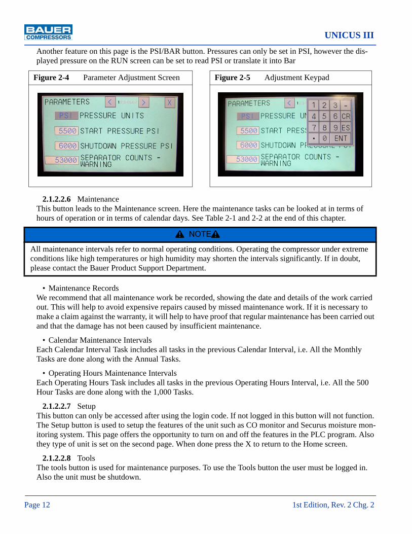
UNICUS III
Page 12 1st Edition, Rev. 2 Chg. 2
Another feature on this page is the PSI/BAR button. Pressures can only be set in PSI, however the dis-played pressure on the RUN screen can be set to read PSI or translate it into Bar
2.1.2.2.6 Maintenance This button leads to the Maintenance screen. Here the maintenance tasks can be looked at in terms of hours of operation or in terms of calendar days. See Table 2-1 and 2-2 at the end of this chapter.
• Maintenance RecordsWe recommend that all maintenance work be recorded, showing the date and details of the work carried out. This will help to avoid expensive repairs caused by missed maintenance work. If it is necessary to make a claim against the warranty, it will help to have proof that regular maintenance has been carried out and that the damage has not been caused by insufficient maintenance.
• Calendar Maintenance IntervalsEach Calendar Interval Task includes all tasks in the previous Calendar Interval, i.e. All the Monthly Tasks are done along with the Annual Tasks.
• Operating Hours Maintenance IntervalsEach Operating Hours Task includes all tasks in the previous Operating Hours Interval, i.e. All the 500 Hour Tasks are done along with the 1,000 Tasks.
2.1.2.2.7 SetupThis button can only be accessed after using the login code. If not logged in this button will not function. The Setup button is used to setup the features of the unit such as CO monitor and Securus moisture mon-itoring system. This page offers the opportunity to turn on and off the features in the PLC program. Also they type of unit is set on the second page. When done press the X to return to the Home screen.
2.1.2.2.8 ToolsThe tools button is used for maintenance purposes. To use the Tools button the user must be logged in. Also the unit must be shutdown.
Figure 2-4 Parameter Adjustment Screen Figure 2-5 Adjustment Keypad
^ NOTE ^
All maintenance intervals refer to normal operating conditions. Operating the compressor under extreme conditions like high temperatures or high humidity may shorten the intervals significantly. If in doubt, please contact the Bauer Product Support Department.

MNL-0375
October 22, 2009 Page 13
2.1.2.2.9 ContactPressing the contact button displays contact information for Bauer Compressors, Inc.
2.2 Starting and Stopping Unit
2.2.1 Before Starting.
1. Check the compressor oil level, See Chapter 3.
2. Ensure that all panels and guards are properly installed.
3. Ensure that all doors are closed.
4. Ensure that the E-Stop Button is pulled out.
2.2.2 To Start Unit.Press the START Button on the Run Screen. (See Figure 2-2)
If the pressure in the system is lower than the Start Pressure, the compressor will start. If the System pres-sure is higher or when the air pressure has increased to operating pressure, the compressor will automati-cally shutdown. The Compressor will automatically restart when the pressure drops below the Start Pressure.
2.2.3 To Stop Unit.Press the STOP Button on the Run screen.
^ WARNING
Once started the compressor and drive motor will start and stop automatically. Stay clear of all moving parts whenever unit has power.
^ NOTE ^
In an emergency the compressor is shutdown by pressing in the E-Stop Button.

UNICUS III
Page 14 1st Edition, Rev. 2 Chg. 2
.
Figure 2-6 Table of Parameter Values
Parameter Default Low High UnitsPASSWORD access #’s supplied by distributor 1,328 9,999 0000
START PRESS lower pressure limit which starts com-pressor 5,800a
a. 15% of Shutdown Press
800 5,700 PSI
SHUTDOWN PRESS upper pressure limit which stops com-pressor
6,000 850 6,000 PSI
SEPCNTWARNING # of cycles till final separator replace-ment warning given
53,000 1,800 900,000
SEPCNTALARM # of cycles till final separator replace-ment alarm shutdown
53,000 2,000 1,000,000
OVERRUNTIMER amount of time before unit shuts down if left unattended
3 2 100 HRS
SHUTDOWNDELAY delaye from when command is given till shtudown occurs
4 0 10 SEC
ACDF TEST TIME amount of time on button held to per-form ACD test
2 2 10 SEC
CO ALARM DELAY time between alarm level reached and alarm gien
0 0 125 SEC
OIL ALARM psi at which low oil press. alarm given 23 3 100 PSISEPCNT RESET current # of cycles for final separator 0 1,000,000ACD1 DELAY ON dely till ACD1 closes 3 1 10 SECACD1 DRAIN TIME length of time ACD1 drains 3 1 10 SEC
ACD1 CYCLE TIME length of time between ACD1 drain cycles
15 3 60 MIN
ACD2 DELAY ON dely till ACD2 closes 3 1 10 SECACD2 DRAIN TIME length of time ACD2 drains 3 1 10 SEC
ACD2 CYCLE TIME length of time between ACD2 drain cycles
15 3 60 MIN
ACD3 DELAY ON dely till ACD3 closes 3 1 10 SECACD3 DRAIN TIME length of time ACD3 drains 3 1 10 SEC
ACD3 CYCLE TIME length of time between ACD3 drain cycles
15 3 60 MIN
ACDF DELAY ON delay till final ACD closes 3 1 10 SECACDF DRAIN TIME length of time final ACD drains 3 1 10 SEC
ACDF CYCLE TIME length of time between final ACD drain cycles
15 3 60 MIN
BACKLIGHT ON Panel light option 10 10 60 MINOIL PRESS TIME DELY (TD)
time delay from startup till oil press. sensor is used 30 4 60 SEC

MNL-0375
October 22, 2009 Page 15
Table 2-1: Calendar Maintenance Interval Tasks
Task Monthly Annually Every Two Years
Calibrate CO Monitor X
Check Oil Level X
Check Final Pressure Shutdown X
Check Automatic Condensate Drain X
Check V-belt X
Service Intake Filter X
Check all connections for leaks X
Inspect Compressor Valves X
Check all fasteners for tightness X
Change Synthetic Oil X
Replace Compressor Oil Filter X
Replace Compressor Valves X
Replace CO Monitor Sensor X

UNICUS III
Page 16 1st Edition, Rev. 2 Chg. 2
Table 2-2: Operating Hours Maintenance Interval Tasks
Task 500 Hours 1,000 Hours 2,000 Hours 3,000 Hours
Check Oil Level X
Check Final Pressure Shutdown X
Check Automatic Condensate Drain X
Check V-belt X
Service Intake Filter X
Check all connections for leaks X
Check fasteners for tightness X
Inspect Compressor Valves X
Change Synthetic Oil X
Replace Oil Filter X
Replace Compressor Valves X
Inspect Pistons and Pistons Rings X

MNL-0375
October 22, 2009 Page 17
2.3 Screen Flow
Figure 2-7 Operator Interface Screen Flow
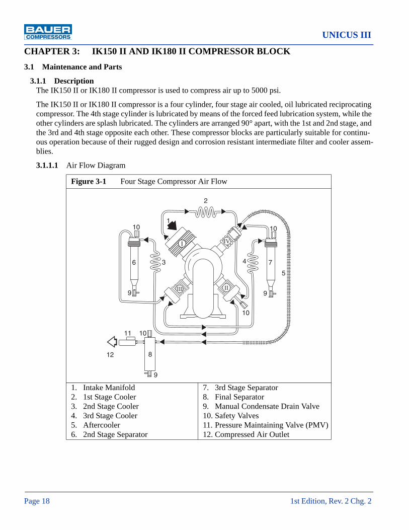
UNICUS III
Page 18 1st Edition, Rev. 2 Chg. 2
CHAPTER 3: IK150 II AND IK180 II COMPRESSOR BLOCK3.1 Maintenance and Parts
3.1.1 DescriptionThe IK150 II or IK180 II compressor is used to compress air up to 5000 psi.
The IK150 II or IK180 II compressor is a four cylinder, four stage air cooled, oil lubricated reciprocating compressor. The 4th stage cylinder is lubricated by means of the forced feed lubrication system, while the other cylinders are splash lubricated. The cylinders are arranged 90° apart, with the 1st and 2nd stage, and the 3rd and 4th stage opposite each other. These compressor blocks are particularly suitable for continu-ous operation because of their rugged design and corrosion resistant intermediate filter and cooler assem-blies.
3.1.1.1 Air Flow Diagram
Figure 3-1 Four Stage Compressor Air Flow
1. Intake Manifold2. 1st Stage Cooler3. 2nd Stage Cooler4. 3rd Stage Cooler5. Aftercooler6. 2nd Stage Separator
7. 3rd Stage Separator8. Final Separator9. Manual Condensate Drain Valve10. Safety Valves11. Pressure Maintaining Valve (PMV)12. Compressed Air Outlet
I
III
IV
II
1
2
3 4
10
6
9
1011
12 8
9
5
7
10
9
10

MNL-0375
October 22, 2009 Page 19
3.1.1.2 Component Location
Figure 3-2 IK150 II Compressor Block (Front View)
1. Service Indicator2. Intake Filter3. Crankcase Vent Feedback Line4. 1st Stage Cylinder5. 2nd/3rd Inter Stage Pressure Valve6. 2nd Stage Separator7. 2nd Stage Cooler8. Oil Pump Housing9. 3rd Stage Cylinder10. Compressed Air Outlet11. Lifting Eyebolt
12. 1st Stage Inter Cooler13. 4th Stage Cylinder14. 4th Stage After Cooler15. Oil Pressure Regulating Valve16. 3rd/4th Inter Stage Pressure Valve17. 3rd Stage Separator18. 1st/2nd Inter Stage Pressure Valve19. 3rd Stage Cooler20. 2nd Stage Cylinder21. Oil Filler with Sight Glass22. Condensate Outlet
1
2
3
4
5
6
7
8
9
10
11
12
13
14
1516
17
1819
20
21
22

UNICUS III
Page 20 1st Edition, Rev. 2 Chg. 2
Figure 3-3 IK180 II Compressor Block (Front View)
1. Service Indicator2. Intake Filter3. Crankcase Vent Feedback Line4. 1st Stage Cylinder5. 2nd/3rd Inter Stage Pressure Valve6. 2nd Stage Separator7. 2nd Stage Cooler8. Oil Pump Housing9. 3rd Stage Cylinder10. Compressed Air Outlet11. Oil Drain Plug12. Lifting Eyebolt
13. 1st Stage Auxiliary Cooler14. 1st Stage Inter Cooler15. 4th Stage Cylinder16. 4th Stage After Cooler17. Oil Pressure Regulating Valve18. 3rd/4th Inter Stage Pressure Valve19. 3rd Stage Separator20. 1st/2nd Inter Stage Pressure Valve21. 3rd Stage Cooler22. 2nd Stage Cylinder23. Oil Filler with Sight Glass24. Condensate Outlet
1
2
3
4
5
6
7
8
9
10
12
11
13
14
15
16
1718
19
20
21
22
23
24

MNL-0375
October 22, 2009 Page 21
3.1.2 Lubrication System
3.1.2.1 Description.The compressor is provided with forced-feed lubrication. The oil pressure is produced by a low revving gear pump. The oil pressure is between 44 psi and 87 psi (3 to 6 bar).
(See Figure 3-4) The oil pump (1) is coupled to and driven by the crankshaft. It pumps oil from the crank-case through an oil filter (2) and the oil pressure regulating valve (3) to the 4th stage cylinder. The oil is then distributed by the guide piston of the 4th stage and lubricates all the moving parts of the compressor block. The oil pressure sensor (5) allows mounting for an optional oil pressure gauge or electronic pres-sure monitoring.
3.1.2.2 Oil Level Check(See Figure 3-5). Check the oil level at the oil filler sight gauge on the compressor block every day before putting the compressor into operation. Oil level must never be below the minimum mark molded into the sight gauge as this will cause severe damage due to lack of lubrication. Overfilling is prevented by the design of the filler neck; i.e. oil should be filled right to the edge of the opening.
^ CAUTION
This oil pump must be operated in the correct direction of rotation, other wise no oil pressure will be built up and the compressor may be damaged.
Figure 3-4 Lubrication Oil System
1. Oil Pump2. Oil Filter3. Oil Pressure Regulating Valve
4. Injection Line to 4th Stage5. Oil Pressure Sensor
1
2
3
4
5

UNICUS III
Page 22 1st Edition, Rev. 2 Chg. 2
3.1.2.3 Oil Change IntervalThe synthetic oil should be changed every 2,000 operating hours or biennially, whichever is reached first.
3.1.2.4 Oil CapacityThe oil capacity is approximately 6.5 quarts (6.0 liters). The amount of oil between the minimum and maximum marks is approximately 1.7 quarts (1.6 liters).
3.1.2.5 Oil Change
1. Run the compressor until it is warm.
2. Remove cap from Oil Filler Sight Gauge.
3. Open the Oil Drain Plug.
4. (See Figure 3-6) Remove two bolts (1) with a 13 mm wrench. Remove cover (2).
5. (See Figure 3-7) Remove the Oil Filter (1) from the rubber gasket at the cover.
6. Mount a new filter element and replace and fasten cover.
7. Fill new oil through filler neck to the Maximum mark on the Oil Fill Sight Gauge.
8. Pour oil in slowly, wait a few minutes until the level settles then replace cap in the Oil Fill Sight Gauge.
9. Return the unit to operation.
Figure 3-5 Oil Filler Sight Gauge
^ CAUTION
Replace the oil filter at every oil change, otherwise when the filter becomes clogged a bypass valve opens and the oil circulates without being filtered.
Max
Min

MNL-0375
October 22, 2009 Page 23
3.1.2.6 Venting the Oil Pump
(See Figure 3-7). If after the start of the compressor no oil pressure builds up, venting the oil pump may be necessary, especially after maintenance and repair work. It may also be necessary if the unit has been operated in the wrong direction of rotation.
1. With the unit running, open the condensate drain valves.
2. Open Oil Pump Vent Plug (2) and wait until oil comes out bubble free.
3. Replace Oil Vent Plug.
Figure 3-6 Removing the Oil Filter Cover Figure 3-7 Replacing the Oil Filter
^ CAUTION
To avoid damage after maintenance the following measures should be strictly adhered to.

UNICUS III
Page 24 1st Edition, Rev. 2 Chg. 2
3.1.3 Intake Filter
A dry micronic filter is used to filter intake air.
3.1.3.1 Service IndicatorThe vacuum in the intake filter is monitored by the Service Indicator (1). When the preset vacuum pres-sure is reached the indicator changes to red and the Filter Element (3) should be replaced
3.1.3.2 Replacing the Filter ElementSee Figure 3-8 and proceed as follows.
1. Open clips on Filter Housing (4) and remove Cover (2).
2. Remove the Filter Element (3).
3. Clean the inside of the Filter Housing with a damp cloth. Take care to prevent any dust from enter-ing the intake manifold.
4. Replace the Filter Element (3).
5. Mount the Cover (1) and fasten with the clips.
6. Reset the Service Indicator (1) by pressing the button.
Figure 3-8 Intake Filter
1. Service Indicator2. Cover
3. Filter Element4. Filter Housing
1
2
3
4

MNL-0375
October 22, 2009 Page 25
Figure 3-9 2nd Stage Intermediate Separator Figure 3-10 3rd Stage Intermediate Separator
1. Separator Body2. Separator Head3. Knurled Nut4. O-ring
5. Center Insert6. Gasket7. Fitting8. Safety Valve
1. Plate2. Hollow Screw3. Center Insert4. O-ring
5. Knurled Nut6. Gasket7. Fitting8. Safety Valve
^ WARNING
Dynamic LoadingThe rapid depressurizing and repressurizing of an intermediate separator during condensate draining sub-jects it to metallurgical stresses. To prevent catastrophic failure with the possibility of damage, injury or
death the intermediate separator must be replaced after 85,000 load cycles. A load cycle equals one depres-surization- repressurization. The Bauer recommended frequency of condensate draining is every fifteen
minutes and is a balance between maximizing the life of the separator chamber and maintaining the quality of the delivered air.
2
8
4
5
1
3
6
7
9
1
2
3
4
5
6
7
8

UNICUS III
Page 26 1st Edition, Rev. 2 Chg. 2
3.1.4 Intermediate Separators
3.1.4.1 DescriptionTwo intermediate separators are mounted on the compressor, one after the 2nd stage and another after 3rd stage. These separators are designed to remove oil and water which accumulates due to the cooling of the air after the compression process. Separation is achieved by means of centrifugal action. In the 2nd stage separator the design of the filter head provides this action. In the 3rd stage separator the centrifugal action is provided by a vortex plate additionally a sintered metal filter is provided to remove dirt contamination.
3.1.4.2 Maintenance The Intermediate Separators require no maintenance.
3.1.5 Compressor Valves and Valve Heads
3.1.5.1 Functional DescriptionThe valve heads of the individual stages form the upper part of the cylinders. The inlet and pressure valves are fitted inside the valve heads.
When the piston moves downwards, the resultant vacuum in the piston cylinder opens the inlet valve. When the piston moves upwards, the inlet valve is closed and the pressure valve opened by the pressure created in the compression process. See Figure 3-11.
3.1.5.2 Initial Operational Check of the ValvesAfter roughly half an hour of operation, the valves should be checked. The outlet piping should be hot if the valves are operating properly. Note that the inlet line to the valve heads should be warm to the touch.
Figure 3-11 Valve Function
^ WARNING
Do not touch the outlet piping with bare hands, use a thermometer.
Intake Discharge
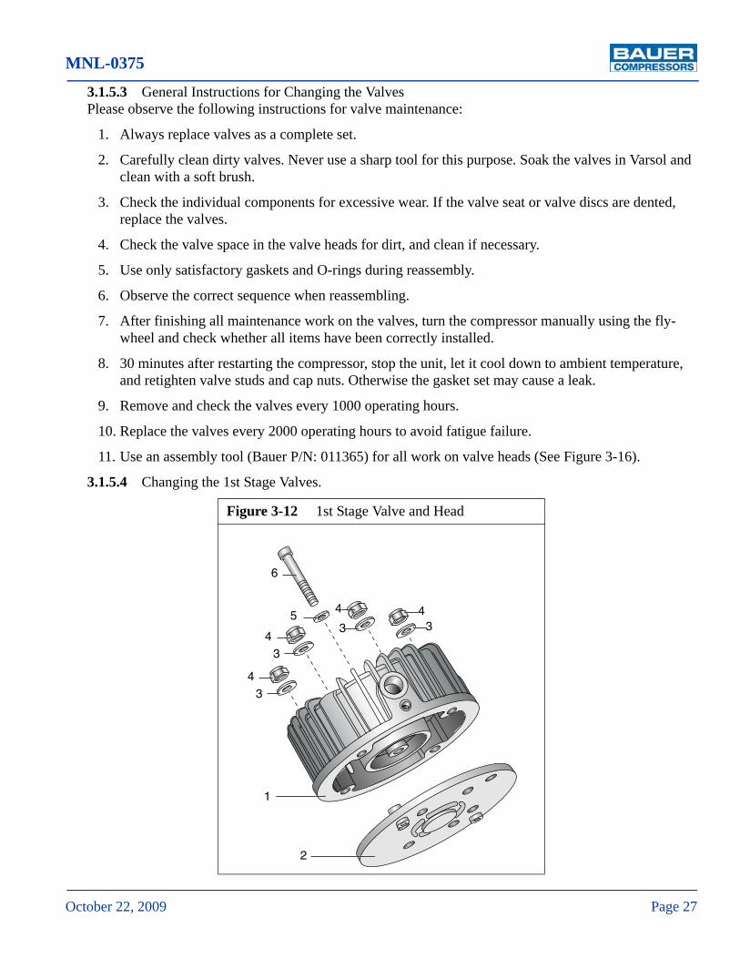
MNL-0375
October 22, 2009 Page 27
3.1.5.3 General Instructions for Changing the ValvesPlease observe the following instructions for valve maintenance:
1. Always replace valves as a complete set.
2. Carefully clean dirty valves. Never use a sharp tool for this purpose. Soak the valves in Varsol and clean with a soft brush.
3. Check the individual components for excessive wear. If the valve seat or valve discs are dented, replace the valves.
4. Check the valve space in the valve heads for dirt, and clean if necessary.
5. Use only satisfactory gaskets and O-rings during reassembly.
6. Observe the correct sequence when reassembling.
7. After finishing all maintenance work on the valves, turn the compressor manually using the fly-wheel and check whether all items have been correctly installed.
8. 30 minutes after restarting the compressor, stop the unit, let it cool down to ambient temperature, and retighten valve studs and cap nuts. Otherwise the gasket set may cause a leak.
9. Remove and check the valves every 1000 operating hours.
10. Replace the valves every 2000 operating hours to avoid fatigue failure.
11. Use an assembly tool (Bauer P/N: 011365) for all work on valve heads (See Figure 3-16).
3.1.5.4 Changing the 1st Stage Valves.
Figure 3-12 1st Stage Valve and Head
1
2
34
5
6
34
3
4
34

UNICUS III
Page 28 1st Edition, Rev. 2 Chg. 2
3.1.5.4.1 Removal Procedure.
1. See Figure 3-12. Unscrew and remove cap nuts (4) and washers (3).
2. Remove Valve Head Assembly (1) from studs in cylinder.
3. Remove Valve (2) and unscrew and remove center screw (6) and washer (5).
3.1.5.4.2 Installation Procedure
1. Fasten new Valve (2) with center screw (6) and washer (5).
2. Place assembled Valve Head (1) on studs in the cylinder.
3. Install washers (3) and cap nuts (4) and tighten to the torque value listed in the Appendix.
3.1.5.5 Changing the 2nd and 3rd Stage ValvesSee Figure 3-13
3.1.5.5.1 Removal Procedure
1. Unscrew and remove hex nut (1).
2. Remove cap holder (2).
3. Insert two screwdrivers into the extraction grooves (4) of the valve caps (3) and lift out the valve caps with O-Rings (5).
4. Check and replace O-Rings if required.
5. Take out valves (6 & 9).
6. Check the valve gaskets (7) and replace if required.
3.1.5.5.2 Installation Procedure
Figure 3-13 2nd and 3rd Stages Valve Heads and Valves
1. Hex Nut2. Cap Holder3. Valve Caps
4. Extraction Groove5. O-Rings6. Inlet Valve
7. Valve Gaskets8. Valve Head9. Discharge Valve
9
7
8
1234
5
6
7
34

MNL-0375
October 22, 2009 Page 29
1. Fit valves(6 & 9) with gaskets (7) and replace.
2. Fit valve caps (3) with O-Rings (5) and replace.
3. Replace cap holder (2) in the proper position.
4. Screw on hex nut (1) and tighten with a torque wrench to the torque value listed in the Appendix.
3.1.5.6 Changing the 4th Stage ValvesSee Figure 3-14
^ CAUTION
The valve cap for the inlet valve protrudes 0.98 in (2.5 mm) out of the valve head more than the valve cap for the discharge valve. The cap holder is designed accordingly.
^ CAUTION
Always change the intake and discharge valves of the 4th stage at the same time.
Figure 3-14 4th Stage Valve and Head1. Inlet Valve2. Valve Head3. Discharge Valve4. O-ring5. Valve Cover6. Gasket7. Socket Head Screw8. Stud9. Gasket10. Acorn Nut
1
2
3
4
5
6
7
8
910

UNICUS III
Page 30 1st Edition, Rev. 2 Chg. 2
3.1.5.6.1 Discharge Valve Removal Procedure
1. Remove piping connected to the 4th Stage Valve Head.
2. Remove Acorn Nut (1) and unscrew Stud (3) three or four turns.
3. Remove the Socket Head Screws (9) and remove the Valve Cover (8).
4. Loosen the Discharge Valve (5) first by turning it with a 13 mm wrench on the flat surfaces.
5. Put two screwdrivers into the groove of the Discharge Valve body. See Figure 3-15.
6. Lift out Discharge Valve together with the O-ring (4)
3.1.5.6.2 Discharge Valve Installation Procedure
1. Check condition of O-ring (4) and replace if necessary
2. Put O-ring (4) into Valve Head (7).
3. Insert Discharge Valve (5) into Valve Head (7).
4. Put on Valve Cover (8).
5. Screw in Socket Head Screws (9) and tighten to the torque value listed in the Appendix
6. Tighten Stud (3) and replace Gasket (2).
7. Tighten Acorn Nut (1) with a torque wrench to the value listed in the Appendix.
Figure 3-15 4th Stage Discharge Valve Removal

MNL-0375
October 22, 2009 Page 31
3.1.5.6.3 Inlet Valve Removal and Installation
1. If the assembly tool shown in Figure 3-16 is unavailable, place two 8 mm diameter metal pins of any length in the holes of the Valve Head (7) and secure them in a vise with the Inlet Valve (6) fac-ing up.
2. Unscrew the Inlet Valve (6) from the Valve Head (7) using the special tool (Bauer P/N 4555-645) supplied with your unit. See Figure 3-17.
3.1.6 Repair and Troubleshooting
3.1.6.1 RepairRepair work can be carried out on the compressor block to a certain extent but a certain level of experi-ence and skill is necessary. It should be noted however that no repair should be carried out on the crank-shaft nor on the bearings and safety valves are not repaired but always replaced
Figure 3-16 Assembly Tool Figure 3-17 Using Special Tool
^ CAUTION
Avoid damaging the special tool or the valve when using the tool, ensure that it is pushed firmly and prop-erly into the sockets in the valve so that it will not tilt when it is turned.

UNICUS III
Page 32 1st Edition, Rev. 2 Chg. 2
3.1.6.2 Troubleshooting
Trouble Cause Remedy
No oil pressure11. Low oil level12. Air trapped in oil pump.
1. Check oil level 2. Vent Oil Pump
Oil foam in crankcase
1. Last stage piston worn2. Last stage pressure valve
defective
1. Operate compressor with final stage valve head removed. If oil flows con-tinuously out of cylinder, replace piston and sleeve.
2. Replace last stage valves.
Compressor output insufficient
1. Condensate drain valves or fittings leaking.
2. Premature opening of final safety valve.
3. Piston rings worn4. Excessive piston clearance5. Pipes leaking
1. Tighten and reseal.2. Clean and adjust final
safety valve.3. Replace4. Replace5. Tighten
Safety valves between stages releasing pressure
1. Intermediate pressure too high
2. Valves not closing properly
1. Service and clean valves.2. Service and clean valves.
Compressor running too hot.
1. Insufficient supply of cool-ing air
2. Intake or outlet valve not closing properly
3. Wrong direction of rotation.
1. Check location for adequate ventilation
2. Check and clean valves, replace as necessary
3. Check arrow on compressor and correct accordingly.
Oil residue in delivered air 1. Improper maintenance of
filters, purifier cartridge saturated.
2. Wrong oil type
1. Service filters, change puri-fier cartridge.
2. Change to proper oil and clean valves.
Compressor rotates in the wrong direction
Electrical phases not connected properly
Reverse two of the three phase leads at the switch box. Do NOT change the leads at the motor ter-minal.

1 2
34
598
6
10
7
This page is inserted to provide proper page sequencing

UNICUS III
Page 34 1st Edition, Rev. 2 Chg. 2
3.1.7 Replacement Parts List
# KIT Qty Part No. Description Notes♦ 1 78577 Crankcase Assembly1 … 1 N20649 Screw2 … 1 68586 Cover Plate3 … 1 N15093 O-ring4 … 1 N26281 Shaft Seal5 … 1 N370 Self Locking Hex Nut6 … 6 N58 Washer7 … 6 78897 Bearing Cover8 … 6 N3138 Stud9 … 1 N18303 Roller Bearing10 … 1 N3810 Circlip11 … 1 N18304 Roller Bearing12 … 1 N18432 Circlip13 … 1 N2635 Circlip
Figure 3-18 Crankcase Assembly
1 2 3 4
5 6
7
8
910
11
12
13
14
15
16
17
18
19 20
2141 22
2324
25
2324
25
3326
2627
27
41
282930
31 32
34
35
36
3738
39 40

MNL-0375
October 22, 2009 Page 35
Figure 3-18 (cont.) Crankcase Assembly
# KIT Qty Part No. Description Notes14 … 1 3177 Gasket15 … 1 N2638 Roller Bearing16 … 1 N4467 Eye Bolt17 … 1 1492 Washer18 … 1 79225 Hexagonal Spacer19 … 1 N4150 Stud20 … 1 80197 Reducer21 … 1 N293 Gasket22 … 1 N204 Plug23 … 12 N16 Washer24 … 12 N312 Hex Head Screw25 … 2 78571 Bracket26 … 2 N4261 Gasket27 … 2 N2796 Plug28 … 1 N25638 Ball Valve29 … 1 N1316 Gasket30 … 1 N4570 Plug31 … 8 N102 Washer32 … 8 N19497 Hex Screw33 … 1 78578 Crankcase34 … 1 78810 Oil Sight Gauge Assembly Items 35 - 3935 … 1 N15412 O-ring36 … 1 80225 Plug37 … 1 78808 Gasket38 … 1 78569 Oil Fill39 … 1 80647 Steel Plate40 … 1 78570 Steel Plate41 … 1 N1314 Gasket

UNICUS III
Page 36 1st Edition, Rev. 2 Chg. 2
# KIT Qty Part No. Description Notes♦ 1 78934 Crankshaft Assembly IK150 II Only1 … 1 79442 Crankshaft Assembly IK180 II Only2 … 1 68587 Bushing3 … 1 N4366 Dowel Screw4 … 1 N108 Spring Washer5 … 1 N2765 Hex Nut6 … 3 4220 Spacers7 … 1 N18310 Circlip8 … 1 N423 Circlip
Figure 3-19 Complete Crankshaft Assembly
75
3
4
1
6
2

MNL-0375
October 22, 2009 Page 37
# KIT Qty Part No. Description Notes♦ 1 79420 1st Stage Piston & Cylinder Asy 120 mm Diameter1 … 1 79017 Cylinder 120 mm Diameter2 … 1 N2621 O-ring3 … 4 N26036 Stud4 … 1 79720 Piston Assembly 120 mm Diameter5 … 1 79719 Piston6 … 1 N2930 Pin, Piston7 … 2 N484 Ring, Retaining8 … 1 N2963 Piston Ring Set 120 mm Diameter
Figure 3-20 K150II 1st Stage Piston and Cylinder
1
2
8
4
67
5
7
3

UNICUS III
Page 38 1st Edition, Rev. 2 Chg. 2
# KIT Qty Part No. Description Notes♦ 1 79704 1st Stage Piston & Cylinder Asy 130 mm Diameter1 … 1 79703 Cylinder 130 mm Diameter2 … 1 N2621 O-ring3 … 4 N26036 Stud4 … 1 79717 Piston Assembly 130 mm Diameter5 … 1 79718 Piston6 … 1 N4109 Pin, Piston7 … 2 N484 Ring, Retaining8 … 1 N4642 Piston Ring Set 130 mm Diameter
Figure 3-21 K180II 1st Stage Piston and Cylinder
1
2
8
4
67
5
7
3

1 2
34
598
6
10
7
This page is inserted to provide proper page sequencing

UNICUS III
Page 40 1st Edition, Rev. 2 Chg. 2
Figure 3-22 2nd Stage Piston and Cylinder Assembly
6
9
8
7
9
10
2
1
54
3

MNL-0375
October 22, 2009 Page 41
# KIT Qty Part No. Description Notes♦ 1 061048 2nd Stage Piston and Cylinder Assembly1 … 1 60572 Cylinder2 ..c 1 N3731 O-ring3 … 4 N215 Stud4 … 4 N58 Washer, Flat5 ..c 4 N370 Nut, Hex, Lock6 … 1 070010 Compressor Piston Assembly7 … 1 N2907 Piston8 … 1 N1429 Pin, Piston9 … 2 N484 Circlip10 … 1 N1461 Piston Ring Set

UNICUS III
Page 42 1st Edition, Rev. 2 Chg. 2
# KIT Qty Part No. Description Notes♦ 1 060107 Piston and Cylinder Assembly1 … 1 82295 Cylinder Guide 60 mm Diameter2 ..c 1 N3731 O-ring 3 … 1 67061 Cylinder 32 mm Diameter4 ..c 1 N7063 O-ring5 … 4 N17462 Stud M8 x 80
Figure 3-23 3rd Stage Piston and Cylinder
8
11109
11
13
1412
2
1
4
3
7 6
5

MNL-0375
October 22, 2009 Page 43
Figure 3-23 (cont.) 3rd Stage Piston and Cylinder
# KIT Qty Part No. Description Notes6 … 4 N58 Washer, Flat 8 mm7 ..c 4 N370 Nut, Hex, Lock M88 … 1 070012 Piston, Guide Assembly 60 mm Diameter9 … 1 60087 Piston, Guide10 … 1 N15409 Pin, Piston11 … 2 N1665 Circlip12 … 1 070013 Piston, Floating Assembly13 … 1 N4378 Piston, Floating14 … 1 N16313 Piston Ring Set 32 mm Diameter

UNICUS III
Page 44 1st Edition, Rev. 2 Chg. 2
# KIT Qty Part No. Description Notes♦ 1 84380 4th Stage Cylinder Assembly1 … 1 070012 Piston Assembly2 … 1 N3731 O-ring3 … 1 82295 Guide Cylinder4 … 1 N7063 O-ring5 … 1 82480 Cylinder6 … 1 N4868 O-ring7 … 1 078043 Piston and Sleeve Assembly 8 … 1 N23755 O-ring9 … 1 N25376 Piston Ring Set
Figure 3-24 4th Stage Piston and Cylinder Assembly
1
2
3
4
5
6
7
8
9
1011
12

MNL-0375
October 22, 2009 Page 45
Figure 3-24 (cont.) 4th Stage Piston and Cylinder Assembly
# KIT Qty Part No. Description Notes10 … 4 N370 Self Locking Hex Nut11 … 4 N58 Washer12 … 4 N17462 Stud

UNICUS III
Page 46 1st Edition, Rev. 2 Chg. 2
# KIT Qty Part No. Description Notes♦ 1 79680 1st Stage Valve Head Assembly1 … † — 1st Stage Valve Head2 … 1 N26029 Plate Valve3 … 4 N16 Washer4 … 4 N644 Self Locking Hex Nut5 … 1 N58 Washer6 … 1 N150 Allen Screw M8 x 60
Figure 3-25 1st Stage Valve Head Assembly
1
2
34
5
6
34
3
4
34

MNL-0375
October 22, 2009 Page 47
# KIT Qty Part No. Description Notes♦ 1 070026 2nd Stage Valve Head Assembly1 … 1 60583 2nd Stage Valve Head2 … 6 N503 Socket Head Cap Screw3 .b. 1 N4067 Valve, Inlet4 .b. 1 N4068 Valve, Discharge5 a.. 2 56668 Gasket, Valve6 … 2 56183 Cap, Valve7 a.. 2 N3997 O-ring8 … 1 62924 Press Pad9 … 2 N4190 Stud10 … 2 N16 Washer, Flat11 a.. 2 N3474 Nut, Hex Lock
Figure 3-26 2nd Stage Valve Head
AU
S
EIN
1
254
6
78
103
11
9

UNICUS III
Page 48 1st Edition, Rev. 2 Chg. 2
# KIT Qty Part No. Description Notes♦ 1 068602 3rd Stage Valve Head Assembly1 … 1 60583 3rd Stage Valve Head2 … 6 N503 Socket Head Cap Screw3 .b. 1 N15273 Valve, Inlet4 .b. 1 N15274 Valve, Discharge5 a.. 2 56668 Gasket, Valve6 … 2 56183 Cap, Valve7 a.. 2 N3997 O-ring8 … 1 62924 Press Pad9 … 2 N4190 Stud10 … 2 N16 Washer, Flat11 a.. 2 N3474 Nut, Hex Lock
Figure 3-27 3rd Stage Valve Head Assembly
AU
S
EIN
1
254
6
78
103
11
9

MNL-0375
October 22, 2009 Page 49
# KIT Qty Part No. Description Notes♦ 1 82096 4th Stage Valve Head Assembly1 .b. 1 081409 Intake Valve2 … 1 82087 Valve Head3 … 1 014121 Discharge Valve4 .b. 1 N2789 O-ring5 … 1 82086 Valve Head Cover6 … 6 N58 Washer7 … 6 N17730 Allen Screw8 … 1 N2738 Stud9 a.. 1 N3625 Gasket10 … 1 N3589 Acorn Nut
Figure 3-28 4th Stage Valve Head Assembly
1
2
3
4
5
6
7
8
910

UNICUS III
Page 50 1st Edition, Rev. 2 Chg. 2
# KIT Qty Part No. Description Notes♦ 1 79240 Flywheel Drive Assembly1 … 1 68623 V-belt Pulley2 … 6 55425 Fan Blade Support3 … 18 79239 Blade, Fan CCW4 … 12 N19495 Hex Head Screw M6 x16 5 … 12 N100 Washer, Split Lock 6 mm6 … 1 68646 Washer7 … 1 N280 Washer, Split Lock8 … 1 N15667 Hex Head Cap Screw M12 x 45
Figure 3-29 Flywheel Drive Assembly
678
1
3
2 45
9

MNL-0375
October 22, 2009 Page 51
# KIT Qty Part No. Description Notes♦ 1 079706 Intake Filter Assembly1 … 1 79679 Manifold, Air Intake2 … 3 N171 Socket Head Cap Screw3 … 1 73036 Housing, Intake Filter4 … 1 79464 Flange5 … 3 N19535 Allen Screw6 a.. 1 N25886 Element, Intake Filter7 … 1 79465 Cover, Filter Housing8 … 1 N2221 Indicator, Maintenance
Figure 3-30 Intake Filter Assembly
12
3 45
6
7
8

UNICUS III
Page 52 1st Edition, Rev. 2 Chg. 2
# KIT Qty Part No. Description Notes♦ 1 077387 Interfilter Assembly1 … † — Filter Housing Available only with 0773872 … † — Filter Head Available only with 0773873 … 1 13937 Collar, Threaded Knurled4 … 1 N3556 O-ring5 … 1 76613 Tube and Baffle6 … 1 N1316 Gasket, Copper7 … 1 N20215 Fitting8 … 1 81807 Safety Valve
Figure 3-31 2nd Stage Interfilter Assembly
2
8
4
5
1
3
6
7
9

MNL-0375
October 22, 2009 Page 53
# KIT Qty Part No. Description Notes♦ 1 081798 3rd Stage Interfilter Assembly♦ 1 81148 Plate1 … 1 81643 Hollow Screw2 … 1 76613 Inset Assembly3 a.. 1 N3556 O-ring4 … 1 13937 Knurled Ring5 … 1 N1316 Gasket6 … 1 N20215 Fitting7 … 1 78706 Safety Valve
Figure 3-32 3rd Stage Interfilter Assembly
1
2
3
4
5
6
7
8

UNICUS III
Page 54 1st Edition, Rev. 2 Chg. 2
# KIT Qty Part No. Description Notes♦ 1 079626 Cooling System Assembly1 … 1 079885 1st Stage Intercooler2 … 1 079927 2nd Stage Intercooler3 … 1 079929 3rd Stage Intercooler4 … 1 079925 Aftercooler5 … 4 79637 Mount6 … 12 6069-M Clamp7 … 12 N15414 Countersunk Screw8 … 16 N58 Washer9 … 14 N108 Lock Washer10 … 12 N370 Self Locking Hex Nut11 … 2 75496 Bushing12 … 4 N503 Allen Screw
Figure 3-33 IK150 II Cooling System Assembly
222
4929
2729
555
37
46
27
3522
36
8
3116
21
2927
28
33
3032
15
16
15930
51
9
13
502927
14
1
4
5552
1
4
5552
1
4
5552
6
7
9
111111
13
12
58
10
4847
15
2740
2740
2740
203940
27
2920
3940
27
2920
3940
27
29
242527
158
23
34
27
29
28
3332
31 15
30
33
54
16
3115
17 45
4128
53
56
28
3338
3230
44
4342
18
35
36
34
19
28

MNL-0375
October 22, 2009 Page 55
Figure 3-33 (cont.) Cooling System Assembly
# KIT Qty Part No. Description Notes13 … 8 N57 Hex Nut14 … 2 60751 Mount15 … 8 N109 Allen Screw16 … 2 57070 Tube Clamp17 … 1 076425 Connecting Tubing18 … 1 070043 Connecting Tubing19 … 1 079923 Connecting Tubing20 … 1 078918 Connecting Tubing21 … 1 070045 Connecting Tubing22 … 1 079919 Connecting Tubing23 … 4 55799 Spacer24 … 8 N1042 Self Locking Hex Nut25 … 8 N102 Washer26 … 8 N3494 Stud27 … 8 N293 Gasket28 … 8 N1316 Gasket29 … 5 N20231 Connector30 … 4 N4530 Plug31 … 4 N2144 Lock Washer32 … 3 N3610 Cap Screw33 … 3 N20195 Connector34 … 2 N20059 Connector35 … 2 N20312 Fitting36 … 2 N20060 Connector37 … 2 N20260 Elbow38 … 2 N724 Allen Screw39 … 1 N20012 Connector40 … 1 N842 Gasket41 … 1 N20201 Connector42 … 1 N1049 Cap Screw43 … 1 N16309 Plug44 … 1 N20155 Adjustable Coupling45 … 1 N20014 Connector46 … 1 79812 Bracket47 … 1 56983 Gasket48 … 1 71148 Connector49 … 1 N20044 Connector50 … 1 N7430 Cap Screw51 … 1 N20003 Elbow Coupling52 … 1 060709 Fan Screen

UNICUS III
Page 56 1st Edition, Rev. 2 Chg. 2
Figure 3-33 (cont.) Cooling System Assembly
# KIT Qty Part No. Description Notes53 … 1 60717 Support54 … 1 60716 Bracket55 … 4 N542 Hex Screw

1 2
34
598
6
10
7
This page is inserted to provide proper page sequencing

UNICUS III
Page 58 1st Edition, Rev. 2 Chg. 2
# KIT Qty Part No. Description Notes♦ 1 080227 Cooling System Assembly1 … 1 079885 1st Stage Intercooler2 … 1 079927 2nd Stage Intercooler3 … 1 079929 3rd Stage Intercooler4 … 1 079925 Aftercooler5 … 4 079637 Mount6 … 12 60694-M Clamp7 … 12 N15414 Countersunk Screw8 … 16 N58 Washer9 … 14 N108 Lock Washer10 … 12 N370 Self Locking Hex Nut
Figure 3-34 IK180 II Cooling System Assembly
5
6
78
10
9
1
2
3
45
5552
11
2740
20
39
27
291
2
3
45
5552
11
2740
2040
27
291
2
45
5552
11
2740
20
27
29
4847
2213
12
54
16
3115
17
4128
53 28
45 3338
3230
44
4342
18
35
3428
19
34
27
29
28
3332
30
31 15
16
23
242526
158
9
13
229
50
14
2927 30
51
28
33
3032
1531
16
21
2927
37
46
4929
2729
27
35
36
8
56
36

MNL-0375
October 22, 2009 Page 59
Figure 3-34 (cont.) IK180 II Cooling System Assembly
# KIT Qty Part No. Description Notes11 … 2 75496 Bushing12 … 4 N503 Allen Screw13 … 8 N57 Hex Nut14 … 2 60751 Mount15 … 8 N109 Allen Screw16 … 2 57070 Tube Clamp17 … 1 076425 Connecting Tubing18 … 1 070043 Connecting Tubing19 … 1 079923 Connecting Tubing20 … 1 078918 Connecting Tubing21 … 1 070045 Connecting Tubing22 … 2 N61 Allen Screw23 … 4 55799 Spacer Disc24 … 8 N1042 Self Locking Hex Nut25 … 8 N102 Washer26 … 8 N3494 Stud27 … 8 N293 Gasket28 … 8 N1316 Gasket29 … 5 N20231 Connector30 … 4 N4530 Plug31 … 4 N2144 Lock Washer32 … 3 N3610 Cap Screw33 … 3 N20195 Connector34 … 2 N20059 Connector35 … 1 080248 Auxiliary Cooler36 … 1 N20060 Connector37 … 2 N20260 Elbow38 … 2 N724 Allen Screw39 … 1 N842 Gasket40 … 1 N20118 Connector41 … 1 N20201 Connector42 … 1 N1049 Cap Screw43 … 1 N16309 Plug44 … 1 N20155 Adjustable Coupling45 … 1 N20014 Connector46 … 1 79812 Bracket47 … 1 56983 Gasket48 … 1 71148 Connector49 … 1 N20044 Connector50 … 1 N7430 Cap Screw

UNICUS III
Page 60 1st Edition, Rev. 2 Chg. 2
Figure 3-34 (cont.) IK180 II Cooling System Assembly
# KIT Qty Part No. Description Notes51 … 1 N20003 Elbow Coupling52 … 1 060709 Fan Screen53 … 1 60717 Support54 … 1 60716 Bracket55 … 4 N542 Hex Screw56 … 1 081801 Safety Valve

MNL-0375
October 22, 2009 Page 61
# KIT Qty Part No. Description Notes♦ 1 079927 2nd Stage Inter-cooler Assembly1 … 2 FER-0012 Ferrule2 … 2 NUT-0057 Nut, Tube3 … 2 N16310 Insert, Tube4 … 6 60738 Clamp, Tube5 … 7 N724 Socket Head Cap Screw6 … 14 N102 Washer, Flat7 … 7 N1042 Nut, Hex Lock 8 … 2 N57 Nut, Hex9 … 4 60694-M Clamp10 … 2 N15119 Countersunk Screw
Figure 3-35 2nd Stage Intercooler
1,2,3
76
4
76
5
4
5
5
4
76
1,2,3
8
9
10
9

UNICUS III
Page 62 1st Edition, Rev. 2 Chg. 2
# KIT Qty Part No. Description Notes♦ 1 79929 3rd Stage Intercooler1 … 6 60738 Clamp, Tube2 … 7 N724 Socket Head Cap Screw3 … 14 N102 Washer, Flat 4 … 7 N1042 Nut, Hex Lock
Figure 3-36 3rd Stage Intercooler
1
2
3
4
1
23
3
4
1 4

MNL-0375
October 22, 2009 Page 63
# KIT Qty Part No. Description Notes♦ 1 084381 Lubricating System Assembly1 … 1 080345 Lubricating System See next Figure2 … 1 78421 Gasket3 … 4 N123 Socket Head Screw4 … 1 84382 Connecting Tube Assembly5 … 1 N20002 Connector6 … 1 N4501 Gasket
Figure 3-37 Lubricating System Assembly
1
2
3
456

UNICUS III
Page 64 1st Edition, Rev. 2 Chg. 2
# KIT Qty Part No. Description Notes♦ 1 080345 Lubricating System1 … 1 N24585 Gear Pump2 … 2 N58 Washer3 … 2 N19506 Hex Head Screw4 … 1 77885 Oil Filter Cover5 … 1 N4058 O-ring6 … 1 N25327 O-ring7 … 1 77774 Rubber Gasket8 a.. 1 N25326 Filter Element9 … 4 N1316 Gasket10 … 1 81050 Regulating Valve11 … 1 N20065 Straight Male Connector12 … 1 N16309 Plug13 … 1 N1049 Screw Cap14 … 3 N52 Plug15 … 2 N2889 Gasket16 … 2 N25328 Socket Head Screw17 … 1 77878 Oil Pump Case18 … 2 N3489 O-ring
Figure 3-38 Lubricating System
1
2
3
18
4
5
67
89
10
11
121314
9
15
16
914
17
914

MNL-0375
October 22, 2009 Page 65
3.2 Automatic Condensate Drain System
3.2.1 DescriptionThe automatic condensate drain system operates electropneumatically and is comprised of the following:
A condensate manifold Two pneumatically operated condensate drain valvesAn electrically controlled solenoid valve A condensate separator/silencerA condensate collector bottle Electronically controlled by the PLC
The automatic condensate drain system drains the intermediate separators and the oil and water separator every 15 minutes during operation. Additionally the automatic condensate drain system unloads the com-pressor during the starting phase and drains these separators at shutdown of the compressor unit.
Figure 3-39 Automatic Condensate Drain System
1. Final Separator Condensate Drain Valve 2. 1st Stage Separator Drain Valves3. Electrical Solenoid Valve4. Condensate Drain Manifold5. Blank Off Plate
6. Manual Condensate Drain Valves7. Separator Condensate Connections8. Control Pressure Connection9. DIN Electrical Connector
1
23
45
6
7
8
9
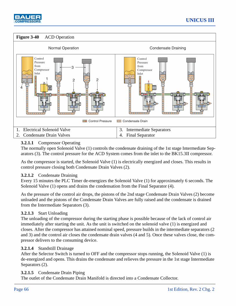
UNICUS III
Page 66 1st Edition, Rev. 2 Chg. 2
3.2.1.1 Compressor OperatingThe normally open Solenoid Valve (1) controls the condensate draining of the 1st stage Intermediate Sep-arators (3). The control pressure for the ACD System comes from the inlet to the BK15.3II compressor.
As the compressor is started, the Solenoid Valve (1) is electrically energized and closes. This results in control pressure closing both Condensate Drain Valves (2).
3.2.1.2 Condensate DrainingEvery 15 minutes the PLC Timer de-energizes the Solenoid Valve (1) for approximately 6 seconds. The Solenoid Valve (1) opens and drains the condensation from the Final Separator (4).
As the pressure of the control air drops, the pistons of the 2nd stage Condensate Drain Valves (2) become unloaded and the pistons of the Condensate Drain Valves are fully raised and the condensate is drained from the Intermediate Separators (3).
3.2.1.3 Start UnloadingThe unloading of the compressor during the starting phase is possible because of the lack of control air immediately after starting the unit. As the unit is switched on the solenoid valve (1) is energized and closes. After the compressor has attained nominal speed, pressure builds in the intermediate separators (2 and 3) and the control air closes the condensate drain valves (4 and 5). Once these valves close, the com-pressor delivers to the consuming device.
3.2.1.4 Standstill DrainageAfter the Selector Switch is turned to OFF and the compressor stops running, the Solenoid Valve (1) is de-energized and opens. This drains the condensate and relieves the pressure in the 1st stage Intermediate Separators (2).
3.2.1.5 Condensate Drain PipingThe outlet of the Condensate Drain Manifold is directed into a Condensate Collector.
Figure 3-40 ACD Operation
1. Electrical Solenoid Valve2. Condensate Drain Valves
3. Intermediate Separators4. Final Separator
Control Pressure Condensate Drain
ControlPressurefromCompressorInlet
Normal Operation
ControlPressurefromCompressorInlet
Condensate Draining
1 2 2
3
4

MNL-0375
October 22, 2009 Page 67
3.2.1.6 Condensate CollectionThe condensate drainage is a mixture of oil, water and air. The Condensate Collection Tank is where the oil and water mixture is stored until it can be disposed of properly.
3.2.2 ACD MaintenanceThe condensate drain valves are provided with manual drain valves to verify correct operation of the automatic system.
The automatic condensate drain system must be serviced once a week as follows:
1. Open all manual drain valves one after the other.
2. Observe the drainage of condensation.
3. If the system drains more than 2 ounces of liquid per stage, either the system or the corresponding condensate drain valve is not working properly.
4. Find the fault and remedy accordingly.
5. If little or no condensation emerges, the automatic system is operating properly.
6. The Condensate Collection Tank should be emptied regularly. Due care must be taken to ensure that any oil which is drained with the condensate is disposed of properly. Check local, state and federal regulations.

UNICUS III
Page 68 1st Edition, Rev. 2 Chg. 2
3.2.3 Replacement Parts List
Item Qty Part No. Description Notes♦ 1 DGM-2348 Automatic Condensate Drain Sub Assembly1 1 MFD-0036 Manifold2 4 N04333 O-ring3 1 N4182 Electrical Solenoid4 1 062523 Condensate Drain Valve See Figure 3-425 2 061010 Condensate Drain Valve See Figure 3-436 3 011430 Manual Condensate Drain Valve See Figure 3-447 1 PLT-0311 Blank Off Plate
Figure 3-41 ACD System
12
3
4
5
6
7
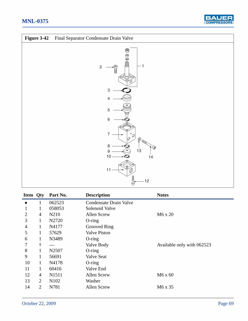
MNL-0375
October 22, 2009 Page 69
Item Qty Part No. Description Notes♦ 1 062523 Condensate Drain Valve1 1 058053 Solenoid Valve2 4 N210 Allen Screw M6 x 203 1 N2720 O-ring4 1 N4177 Grooved Ring5 1 57629 Valve Piston6 1 N3489 O-ring7 † — Valve Body Available only with 0625238 1 N2507 O-ring9 1 56691 Valve Seat10 1 N4178 O-ring11 1 60416 Valve End12 4 N1511 Allen Screw M6 x 6013 2 N102 Washer14 2 N781 Allen Screw M6 x 35
Figure 3-42 Final Separator Condensate Drain Valve
12
3
4
5
6
7
89
10
11
12
13
14

UNICUS III
Page 70 1st Edition, Rev. 2 Chg. 2
Item Qty Part No. Description Notes♦ 1 061010 Condensate Drain Valve Assembly1 4 N796 Socket Head Cap Screw2 1 N3764 Hex Nut3 1 61007 Top Flange4 1 57353 Adjusting Screw5 1 N7091 O-ring6 1 N2720 O-ring7 1 N04177 Sealing Ring
Figure 3-43 1st Stage Separators Condensate Drain Valves
12
3
4
5
6
7
8
9
10
11
1213
14
15
1617
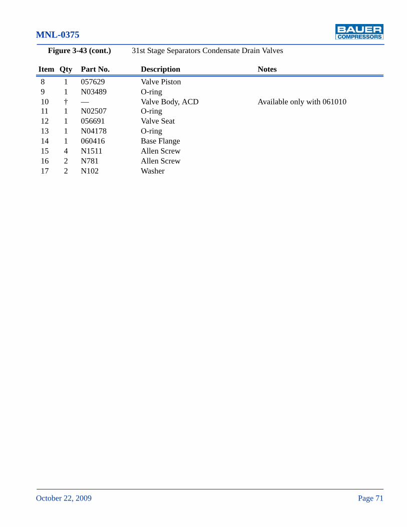
MNL-0375
October 22, 2009 Page 71
Figure 3-43 (cont.) 31st Stage Separators Condensate Drain Valves
Item Qty Part No. Description Notes8 1 057629 Valve Piston9 1 N03489 O-ring10 † — Valve Body, ACD Available only with 06101011 1 N02507 O-ring12 1 056691 Valve Seat13 1 N04178 O-ring14 1 060416 Base Flange15 4 N1511 Allen Screw16 2 N781 Allen Screw17 2 N102 Washer
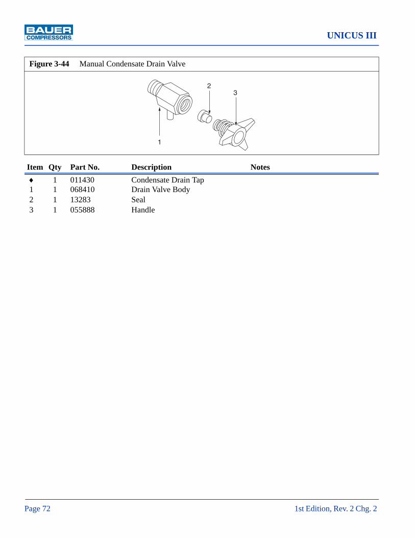
UNICUS III
Page 72 1st Edition, Rev. 2 Chg. 2
Item Qty Part No. Description Notes♦ 1 011430 Condensate Drain Tap1 1 068410 Drain Valve Body2 1 13283 Seal3 1 055888 Handle
Figure 3-44 Manual Condensate Drain Valve
1
23

MNL-0375
October 22, 2009 Page 73
3.2.4 Condensate Collector Replacement Parts List
Item Qty Part No. Description Notes1 1 CAP-0056 Condensate Collector Cover2 1 GKT-0050 Gasket3 2 ELM-0160 Fine Filter Element4 2 ELM-0161 Coarse Filter Element5 1 HUS-0050 Condensate Collector6 1 SWT-0265 Float Switch7 1 TNK-0092 Condensate Collection Tank8 1 VAL-0386 Manual Drain Valve9 1 PLU-0011 Plug10 1 MFD-0036 ACD Manifold
Figure 3-45 Condensate Collector
1
2
3
4
5
6
7
8
9
10

UNICUS III
Page 74 1st Edition, Rev. 2 Chg. 2
3.2.5 Trouble shooting
Trouble Cause Remedy
Solenoid Valve does not drain.1. Solenoid valve receives no
electrical signal2. Plunger of drain valve
sticking
1. Check connections, Timer. Replace if necessary.
2. Clean or replace valve.
Condensate Drain Valve does not drain.
1. Solenoid valve does not depressurize drain valve.
2. No control medium avail-able.
3. Solenoid valve sticking.4. Drain valve sticking in open
position
1. Check solenoid valve, replace if necessary
2. Check supply lines3. Clean or replace4. Clean or replace

MNL-0375
October 22, 2009 Page 75
CHAPTER 4: PURIFICATION SYSTEM4.1 Introduction
The purpose of all Bauer breathing air purification systems is to remove Carbon Monoxide, oil, water, taste and odor from the compressed air stream before final delivery.
The purpose of all Bauer industrial air purification systems is to remove oil and water from the com-pressed air stream before final delivery.
4.1.1 General Purification System Procedures
1. Keep an accurate record of operating hours to ensure exact attention to maintenance intervals
2. Change all cartridges before reactivating a compressor unit that has been out of service more than three months. Leave cartridges in the unit as long as it is out of service.
3. While out of service keep all condensate drain valves closed. Maintain a pressure of 700 to 1,100 psi (50 to 80 bar) within the system to prevent moisture from entering the compressor and purifica-tion system.
4.1.2 Chamber Safety BoreThe chambers in all Bauer purification systems are designed to prevent pressurization if the cartridge is missing, not seated properly or damaged (See Figure 4-1). Without a cartridge properly in place the safety bore is not sealed, the air escapes into the atmosphere, no pressure can be built up and thus it is ensured that unfiltered air is not supplied to the consuming device. If air is escaping from the safety bore remove and check cartridge. If necessary replace the cartridge or O-rings.
^ WARNING
Industrial Air Purification System cartridges do not remove Carbon Monoxide and must not be used in breathing air applications.

UNICUS III
Page 76 1st Edition, Rev. 2 Chg. 2
4.1.3 Manual Condensate DrainageThe condensate must be drained from the oil and water separator before changing any cartridge, before beginning each filling procedure and in the absence of an Automatic Condensate Drain System, every fifteen minutes during the filling procedure. This is done by slowly opening the condensate drain valves. They are opened approximately 1/3 of a turn to the left and held open until the condensate is completely drained. The condensate drain valves close by spring pressure but if necessary may be tight-ened by hand to ensure they are completely air tight.
4.1.4 Model, Serial Number and Part Number Identification
4.1.4.1 Compressor DataplateThe model number, date of manufacture and serial number can be found on the compressor unit identi-fication plate in the main electrical enclosure and frame.
Figure 4-1 Cartridge Safety Venting
Figure 4-2 Purification System Dataplates (typical)
Purification System Cartridge Installation
SafetyVent
Cartridge Installed
SafetyVent
No Cartridge Installed
CARTRIDGE FOR
CARTRIDGE NO.
LBL-
CARTRIDGE TO BEINSTALLED
1328 Azalea Garden Road - Norfolk Virginia 23502-1944Phone: (757) 855-6006 Fax: (757) 855-8224
MODEL NO.
MAX. PRESSURE
AIR PROCESSED
O-RING
BACK-UP RING
psig
cu. ft.
LBL-
PURIFICATIONSYSTEM

MNL-0375
October 22, 2009 Page 77
4.1.4.2 Purification System DataplateRefer to the compressor unit purification system data plate (See Figure 4-2) on the compressor front to determine your purification system model and specifications.
4.1.4.3 Cartridge Installation DataplateThe function performed by each chamber in the purification system is determined by the type of car-tridge installed in that chamber. Refer to the cartridge installation data plate on the chamber to deter-mine the purpose and part number of the cartridge installed in that chamber. (See Figure 4-2).
4.1.5 Breathing Air Purification System Configurations
Purification System Number and Type of Cartridges Processing Capacity
Dryer Purification Securus® cubic ft (ft)3
P0 Combined 3,200
P1 … 1 … 15,000
P2 … 1 … 40,000
P2 with Securus® … … 1 67,000
P4 1 1 … 60,000
P5 1 1 … 90,000
P5 with Securus® 1 … 1 150,000
P10 2 1 140,000
P10 with Securus® 2 … 1 230,000
P12a
a. P12 and P14 have the Securus® Electronic Moisture Monitor System as standard equipment.
1 1 420,000
P14 a 2 1 650,000
P31 Combined 11,760
P41 … 1 28,700
P41 with Securus® … … 1 47,000
P42 1 1 … 64,000
P42 with Securus® 1 … 1 107,000
P43 2 1 … 100,000
P43 with Securus® 2 … 1 164,000

UNICUS III
Page 78 1st Edition, Rev. 2 Chg. 2
4.1.6 Industrial Purification System Configurations
4.1.7 Cartridge Operating LifeEvery Bauer Purification System is designed to process a certain volume of air before the cartridges require replacement. By using special test equipment that measures the quality of air at the outlet any quality reduction may be detected. However as most compressor owners do not have this test equip-ment the recommended method of determining cartridge operating life is to maintain a written record of the volume of air processed by the purification system.
Each Bauer compressor block is rated to produce a standard volume of air per minute and by using this number and the air processing capability of the purification system it is possible to calculate the maxi-mum operating hours before the cartridges need to be replaced. See Paragraph 4.1.7.1 for the method of determining this figure.
The ambient air temperature and its ability to cool the compressor will effect the operating life of the cartridge. See Paragraph 4.1.7.2 for the method of calculating this adjustment factor.
The optimum place to measure the temperature is at the inlet to the final separator as this best reflects the temperature of the air as it enters the chambers. Experience has shown that this temperature is
Purification System Number and Type of Cartridges Processing Capacity
Dryer Purification Securus® cubic ft (ft)3
P0 Combined 3,200
P1 … 1 … 15,000
P2 … 1 … 40,000
IP2 with Securus® … … 1 67,000
P4 1 1 … 60,000
P5 1 1 … 90,000
IP5 with Securus® 1 … 1 150,000
P10 2 1 140,000
IP10 with Securus® 2 … 1 230,000
P31 Combined 11,760
IP41 with Securus® … … 1 47,000
IP42 with Securus® 1 … 1 107,000
IP43 with Securus® 2 … 1 164,000

MNL-0375
October 22, 2009 Page 79
approximately 10 °F above the ambient temperature. Therefore for the purpose of calculating cartridge operating life use the Ambient Air Temperature plus 10 °F.
A form titled Air Purification Cartridge Operating Hours is found in Paragraph 4.1.7.3 and in the Appendices. It is used for recording the ambient temperature, operating time and adjustment factor. It is suggested that it be copied, placed in a protective folder and kept with the unit to record the adjusted operating hours. An example of how this form is used is shown in Figure 1-5.
4.1.7.1 Calculating the Maximum Cartridge Operating Hours
1. From the purification system data plate (See Figure 4-2) on the purification chamber determine the Air Processed (cu.ft.)
2. From the paragraph titled Compressor Specifications in the instruction manual for your compressor unit determine the Charging Rate in SCFM of your compressor.
3. Divide the Air Processed by the Charging Rate to obtain the Maximum Operating Time in minutes
4. Divide the Maximum Operating Time in minutes by 60 to obtain the Maximum Operating Hours.
5. Record the answer on the Air Purification Cartridge Operating Hours form.
4.1.7.2 Calculating the Adjusted Cartridge Operating Hours
1. Using the Air Purification Cartridge Operating Hours form (FORM-0018) record the Date, Operat-ing Hours and Ambient Air Temperature plus 10 °F.
2. Using either the graph or the chart in Figure 1-4 determine the Correction Factor.
3. Divide the Operating Hours by the Correction Factor and record it under the column labeled Today.
4. Add the hours recorded in Today to the previous Total and record it as the current Total.
5. When the Total approaches the Maximum Operating Hours replace the Cartridges.

UNICUS III
Page 80 1st Edition, Rev. 2 Chg. 2
Figure 4-3 Correction Factor for Cartridge Operating Hours
Figure 4-4 Example Record of Adjusted Operating Hours
°F [°C x 9/5 +32]
°C [(°F - 32) x 5/9]
Cartridge Op. Hrs. Correction factor
50 122 0.21
40 104 0.34
30 86 0.58
20 68 1.00
10 50 1.81
0 32 3.44
0.0
0.5
1.0
1.5
2.0
2.5
3.0
3.5
0 10 20 30 40 50Ambient Temperature in °C
Car
trid
ge O
p. H
rs.
Con
vers
ion
Fact
or
Date OperatingHours
Ambient Temp.during Compression
CorrectionFactor
Adjusted Cartridge HoursToday Total
10/19/04 8 92°F (33 °C) 0.48 16.66 16.66
11/01/04 4 45°F (7.2 °C) 2.25 1.78 18.44

MNL-0375
October 22, 2009 Page 81
4.1.7.3 Air Purification Cartridge Operating Hours Form
Date Operating hours
Ambient temp.during compression
Correction factor
Adjusted cartridge hours
Today Total

UNICUS III
Page 82 1st Edition, Rev. 2 Chg. 2
4.2 P5S Securus II® Purification System
4.2.1 P5S Securus II® Purification System Major ComponentsThe P5S Securus II® Purification System major components are an Oil and Water Separator, a Dryer Chamber and a Securus II® Purification Chamber. Figure 4-5 shows the functional interconnection of all the components.
Figure 4-5 P5S Securus II® Purification System
1. Oil and Water Separator2. Condensate Drain Valve3. Check Valves
4. Dryer Chamber5. Securus® Chamber6. Bleed Valve
7. Pressure Maintaining Valve8. Safety Valve9. Securus® Transmitter
OUT
IN
7
3
8
1
2
3
4
5
6
9

MNL-0375
October 22, 2009 Page 83
4.3 Component Description
4.3.1 Oil and Water Separator
The air leaving the final stage is cooled in the aftercooler to approximately 18 - 27° F (10 -15° C) above ambient temperature and then enters the oil and water separator. The oil and water separator works by means of a sintered metal filter which separates liquid oil and water particles from the compressed air
4.3.2 ChamberEach chamber is made up of an anodized aluminum housing and a filtering cartridge. There are two gen-eral types of filtering cartridges, drying or purifying. The cartridge type is determined by the ingredients packed in the cartridge. The chamber is named after the type of cartridge it contains, i.e. dryer chamber or purification chamber.
4.3.3 Cartridge
4.3.3.1 Cartridge ConstructionThe cartridge casing, top and bottom are aluminum and are packed with one or more of the following.
1. A catalyst to convert carbon monoxide to carbon dioxide.
2. Activated carbon which absorbs oil vapors effecting taste and odor.
3. Molecular sieve to absorb oil and water.
^ WARNING
The rapid depressurizing and repressurizing of the oil and water separator during condensate draining sub-jects it to metallurgical stresses. To prevent catastrophic failure with the possibility of damage, injury or death the oil and water separator (P/N 079416) must be replaced after a predetermined number of cycles. One load cycle equals one pressurization plus one depressurization. Units operating between 3,000 and 5,000 psi = 130,000 load cycles (32,500 hours of operation)Units operating between 5,000 and 6,000 psi = 22,000 load cycles (13,750 hours of operation)
The Bauer recommended frequency of condensate draining is every fifteen minutes and is a balance between maximizing the life of the separator chamber and maintaining the quality of the delivered air.
Figure 4-6 Oil and Water Separator Labels
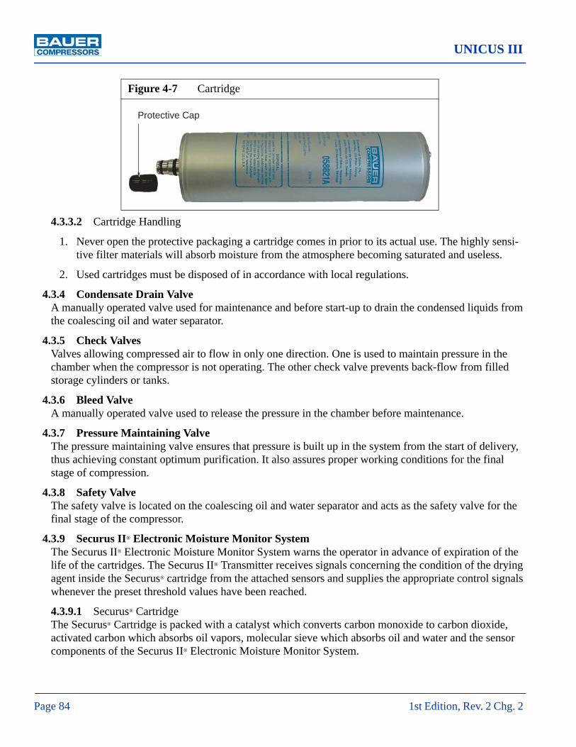
UNICUS III
Page 84 1st Edition, Rev. 2 Chg. 2
4.3.3.2 Cartridge Handling
1. Never open the protective packaging a cartridge comes in prior to its actual use. The highly sensi-tive filter materials will absorb moisture from the atmosphere becoming saturated and useless.
2. Used cartridges must be disposed of in accordance with local regulations.
4.3.4 Condensate Drain ValveA manually operated valve used for maintenance and before start-up to drain the condensed liquids from the coalescing oil and water separator.
4.3.5 Check ValvesValves allowing compressed air to flow in only one direction. One is used to maintain pressure in the chamber when the compressor is not operating. The other check valve prevents back-flow from filled storage cylinders or tanks.
4.3.6 Bleed ValveA manually operated valve used to release the pressure in the chamber before maintenance.
4.3.7 Pressure Maintaining ValveThe pressure maintaining valve ensures that pressure is built up in the system from the start of delivery, thus achieving constant optimum purification. It also assures proper working conditions for the final stage of compression.
4.3.8 Safety ValveThe safety valve is located on the coalescing oil and water separator and acts as the safety valve for the final stage of the compressor.
4.3.9 Securus II® Electronic Moisture Monitor SystemThe Securus II® Electronic Moisture Monitor System warns the operator in advance of expiration of the life of the cartridges. The Securus II® Transmitter receives signals concerning the condition of the drying agent inside the Securus® cartridge from the attached sensors and supplies the appropriate control signals whenever the preset threshold values have been reached.
4.3.9.1 Securus® CartridgeThe Securus® Cartridge is packed with a catalyst which converts carbon monoxide to carbon dioxide, activated carbon which absorbs oil vapors, molecular sieve which absorbs oil and water and the sensor components of the Securus II® Electronic Moisture Monitor System.
Figure 4-7 Cartridge
Protective Cap

MNL-0375
October 22, 2009 Page 85
4.3.9.2 Securus II® TransmitterThe Securus II® Transmitter relays the operating condition of the Securus II® Electronic Moisture Monitor System to the operator control interface. The Securus II® issues a warning when the Securus® cartridge is approaching saturation, to warn the user to prepare to change the Securus® cartridge. Once the Securus® cartridge has reached total saturation the Securus II® monitor will issue an alarm condition to the operator interface and shut down the unit. Once the Securus® cartridge is replaced the compressor unit can be restarted.
4.4 Maintenance
4.4.1 Oil and Water SeparatorTo remove the sintered metal filter proceed as follows: (See Figure 4-8). Disconnect the power and shut off the inlet supply line if applicable.
1. Depressurize the system by means of the bleed valve.
2. Remove the tubes connected to the side of the filter head (1).
3. Unscrew and remove the filter head.
4. Unscrew the sintered metal filter (2) from the filter head.
5. Remove the center screw (3) to remove the sintered metal filter.
6. Clean the sintered metal filter using hot soapy water. Blow dry with compressed air.
7. After cleaning the element, record the number of operating hours to ensure exact attention to the maintenance intervals.
8. Lubricate the threads and O-rings as well as the threaded part of the sintered metal filter with petro-leum jelly. Apply sparingly.
9. Dry the inside of the filter housing with a clean cloth and check for corrosion before reinstalling the sintered metal filter.
10. In the event you discover corrosion, replace the corroded parts with new Bauer parts.
11. Reinstall the sintered metal filter assembly and filter head.
12. Replace all removed tubes, close all valves and check for leaks

UNICUS III
Page 86 1st Edition, Rev. 2 Chg. 2
Figure 4-8 Oil and Water Separator Figure 4-9 Sintered Metal Filter Assembly
1. Filter Head2. Sintered Metal Filter
3. Center Screw4. O -rings
1. Threaded Insert2. Filter Bottom3. Inner Filter
4. Outer Filter5. Filter Head
1
2
3
4

MNL-0375
October 22, 2009 Page 87
4.4.1.1 Removal of the Securus II® Transmitter.
The Securus II® Transmitter is removed and replaced by rotating the blue plastic Securus II® Transmitter approximately ½ turn. It is not necessary to disconnect or remove the DIN Connector.
Figure 4-10 Removal of the Securus II® Transmitter
1. Securus II® Transmitter 2. DIN Connector
NOTICE
If the DIN Connector is removed, ensure that it is replaced in exactly the same position,otherwise electrical damage to the unit may occur.
12

UNICUS III
Page 88 1st Edition, Rev. 2 Chg. 2
4.4.2 Cartridge ReplacementTo change the purification cartridge, proceed as follows. (See Figure 4-11)
1. Disconnect the power and shut off the inlet supply line, if applicable.
2. Depressurize the system by means of the bleed valve.
3. If the chamber is part of the Securus II® Moisture Monitor System, remove the Securus II® Trans-mitter. See Paragraph 4.4.1.1.
4. Unscrew the chamber head using the special wrench supplied.
5. Pull out the cartridge using the lifting ring on top of the cartridge.
6. Dry the inside of the chamber with a clean cloth and check for corrosion.
7. Replace all corroded parts with new Bauer parts.
8. Remove the shipping covering and the protective cap from the bottom of the cartridge.
9. Lubricate the O-rings with white petroleum jelly. Apply sparingly.
10. Install the new cartridge. Be sure the cartridge snaps into place.
11. Reinstall the chamber head.
12. Close the bleed valve, restore the power and reconnect the inlet supply line, if applicable.
4.4.2.1 Leaking at the Safety Bore
1. Remove the cartridge following the steps in Paragraph 4.4.2.
2. Install cartridge if missing.
Figure 4-11 Cartridge Replacement
NOTICE
If air is detected bleeding out from the bottom of the chamber, the cartridge has not been installed properly or is missing. Follow the instructions in Paragraph 4.4.2.1

MNL-0375
October 22, 2009 Page 89
3. Remove cartridge and inspect O-rings.
4. Replace O-rings if necessary.
5. Ensure protective caps and devices have all been removed.
6. Replace cartridge following steps 8. to 11. in Paragraph 4.4.2

UNICUS III
Page 90 1st Edition, Rev. 2 Chg. 2
4.5 Replacement Parts List
Item Qty Part No. Description Notes1 1 079416 Oil and Water Separator See Figure 4-132 1 011430 Condensate Drain Valve3 2 VAL-0007 Check Valves4 1 080144 27” Dryer Chamber See Figure 4-145 1 080145 Securus® Chamber See Figure 4-156 1 VAL-0377 Bleed Valve7 1 VAL-0053 Pressure Maintaining Valve8 1 VAL-0169 Safety Valve9 1 MNR-0042 Securus II® Transmitter 24 VDC
Figure 4-12 P5 Purification System Parts List
OUT
IN
7
3
8
1
2
3
4
5
6
9

MNL-0375
October 22, 2009 Page 91
Item Qty Part No. Description Notes♦ 1 079416 Oil and Water Separator Assembly1 † — Separator Head Available only with 0794162 2 N04586 O-Ring3 1 061860 Sintered Metal Filter 3a 1 N15133 O-Ring 3b 2 N04496 O-Ring, small 3c 2 N04385 O-Ring, large 3d 1 061858 Sleeve Element, large 3e 1 061859 Sleeve Element, small 3f 1 N07091 O-Ring 3g 1 061857 Screw4 † — Separator Housing Available only with 0794165 † — Bottom Plug Available only with 079416
Figure 4-13 Oil and Water Separator Parts List
1
2
3
4
5
2
a
bc
b
c
d
e
f g

UNICUS III
Page 92 1st Edition, Rev. 2 Chg. 2
Item Qty Part No. Description Notes♦ 2 80144 Chamber Assembly 27”1 2 012293 Tool Post Screw2 1 061237 Cover Plate3 † — Filter Head Available only with 801444 2 N04736 Back-up Ring5 2 N04735 O-ring6 † — Filter Housing Available only with 801447 † — Filter Bottom Available only with 801448 1 058825A Dryer Cartridge MS
Figure 4-14 27” Chamber Assembly Parts List
1
2
3
4
4
5
5
6
7
8

1 2
34
598
6
10
7
This page is inserted to provide proper page sequencing

UNICUS III
Page 94 1st Edition, Rev. 2 Chg. 2
Item Qty Part No. Description Notes♦ 1 80145 Securus® Chamber Assembly Replaces 1 P/N 80144 in P5S1 † — Bottom Plug Available only with 801452 2 N04736 Backup Ring3 2 N04735 O-ring4 1 060037A Securus® Cartridge5 † — Filter Body Available only with 801456 1 059855 Nut7 1 059852 Drawback Screw8 1 059854 Loose Pin9 1 060062 Compression Spring10 1 059853 Fixed Pin
Figure 4-15 Securus® Electronic Moisture Monitor System Parts List
1
2
3
4
5
3
2
9
67
8
10
11
12
13
14
15
16
17
18

MNL-0375
October 22, 2009 Page 95
Figure 4-15 (cont.) Securus® Electronic Moisture Monitor System Parts List
Item Qty Part No. Description Notes11 1 059851 Bolt12 1 002181 Compression Spring13 † — Filter Head Available only with 8014514 1 06135 Cover Plate15 2 012293 Tool Post Screw16 1 059850 Socket, RF type17 1 MNR-0042 Securus II® Transmitter 24 VDC18 1 CON-0319 Securus II® Connector
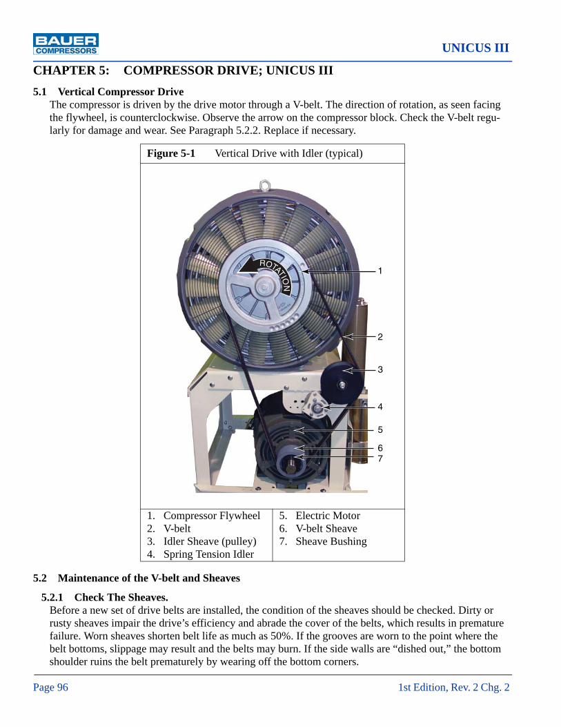
UNICUS III
Page 96 1st Edition, Rev. 2 Chg. 2
CHAPTER 5: COMPRESSOR DRIVE; UNICUS III5.1 Vertical Compressor Drive
The compressor is driven by the drive motor through a V-belt. The direction of rotation, as seen facing the flywheel, is counterclockwise. Observe the arrow on the compressor block. Check the V-belt regu-larly for damage and wear. See Paragraph 5.2.2. Replace if necessary.
5.2 Maintenance of the V-belt and Sheaves
5.2.1 Check The Sheaves. Before a new set of drive belts are installed, the condition of the sheaves should be checked. Dirty or rusty sheaves impair the drive’s efficiency and abrade the cover of the belts, which results in premature failure. Worn sheaves shorten belt life as much as 50%. If the grooves are worn to the point where the belt bottoms, slippage may result and the belts may burn. If the side walls are “dished out,” the bottom shoulder ruins the belt prematurely by wearing off the bottom corners.
Figure 5-1 Vertical Drive with Idler (typical)
1. Compressor Flywheel2. V-belt3. Idler Sheave (pulley)4. Spring Tension Idler
5. Electric Motor6. V-belt Sheave7. Sheave Bushing
1
2
3
4
5
67
ROTATION

MNL-0375
October 22, 2009 Page 97
5.2.2 Check the V-beltCheck the V-belt regularly for damage and wear. Replace if necessary. V-belt tension is adjusted auto-matically by the spring tension idler.
5.2.3 Replacing the BeltTo replace the belt use a spanner wrench or special tool if provided to pull idler pulley away from belt. The belt should be slack enough to pull off of the flywheel and motor’s sheave. Replace with the correct replacement belt and let the idler slowly engage the belt, making it tight.
5.2.4 Replacing the SheaveA gear puller can be used to remove the sheave and sheave bushing from the motor’s drive shaft. Ensure the drive shaft is clean then slide the new sheave onto the drive shaft. Bolt the sheave bushing onto the sheave then tap the feathered key into the key slot. Ensure the feathered key is snug with both the shaft and sheave. There should no play once the key is in place. The feathered key should run the entire length of the bushing and sheave keyslots.
NOTICE
Do Not let the idler return until new belt is in place. If the idler does return to its neutral position it is extremely hard to get it back to the proper spring position.

UNICUS III
Page 98 1st Edition, Rev. 2 Chg. 2
5.3 Replacement Part List
Item Qty Part No. Description Notes♦ UNICUS III 201 1 IK 150 II Compressor Block2 2 BET-0049 V-belt3 1 SHE-0266 Idler Sheave4 1 IDL-0009 Idler— 1 BRK-0512 Idler Bracket5 1 MTR-0024 Electric Motor 15 Hp, 3 Phase6 1 SHE-0030 V-belt Sheave7 1 BUS-0001 Sheave Bushing
Figure 5-2 UNICUS III, Vertical Drive with Idler
1
2
3
4
5
67
ROTATION

MNL-0375
October 22, 2009 Page 99
Figure 5-2 (cont.) UNICUS III, Vertical Drive with Idler
Item Qty Part No. Description Notes♦ UNICUS III 26 1 1 IK 150 II Compressor Block2 2 BET-0102 V-belt3 1 SHE0266 Idler Sheave4 1 IDL-0009 Idler— 1 BRK-0512 Idler Bracket5 1 MTR-0065 Electric Motor 20 Hp, 3 Phase6 1 SHE-0241 Sheave7 1 BUS-0020 Sheave Bushing

UNICUS III
Page 100 1st Edition, Rev. 2 Chg. 2
CHAPTER 6: ELECTRICAL PANEL, ASY-10586.1 Overview
The following instructions apply to units that use Electrical Panel, ASY-1058 and Operator Interface, MNR-0049.
The Electrical Panel, ASY-1058, provides logical control and safety shutdowns for the compressor equipment. All necessary time delays, counters, shutdowns, sequencing and safety features are incorpo-rated into a proprietary software program permanently saved into PLC memory using EEPROM tech-nology. The software program used in this Electrical Panel is based on the pressure and use of the compressor.
The input/output device for normal operation of the compressor unit is the Operator Interface, MNR-0049. In an emergency the compressor is shutdown with the E-Stop Button.
6.2 Electrical PanelThis Electrical Panel is designed for use with 5, 7½, 10, 15 or 20 horsepower electric motors. It is also designed for supply voltages from 208 VAC to 460 VAC, single or three phase and 50Hz or 60 Hz. All supply voltage options are not available with each horsepower rating.
The basic panel components consist of a Programmable Logic Controller (PLC), Motor Starter, Over-load Relay, Power Transformer, Fuses, Overload Reset Button, Hourmeter, terminal strips for internal
Figure 6-1 ASY-1058 and MNR-0049

MNL-0375
October 22, 2009 Page 101
wiring and connectors for attachment to wire harnesses. The panel is built to match the horsepower, voltage, phase and frequency of the customer’s requirements.
6.2.1 Wiring DiagramThe wiring diagram for your specific Compressor Unit is stored inside the Electrical Panel. If a wiring diagram for your machine is not found inside the Electrical Panel, then please call Bauer Compressors Product Support Group for a replacement. Please have the serial number of the compressor available; it is written on a label (See Figure 6-2) inside the Electrical Panel door.
6.2.2 Electrical Panel Interior AccessThe interior of the Electrical Panel is accessed by using a coin or screwdriver to turn the latch on the front of the Electrical Panel.
6.2.3 Optional Equipment Optional equipment which may also be housed in the Electrical Panel is any of five Communication Modules. An EEPROM Memory Module may also be an option in the Electrical Panel.
6.3 AC Power RequirementsThe Electrical Panel must be supplied with electricity of the correct voltage, phase, and frequency to ensure proper operation. Wiring and conduit selection must be in accordance with all national, state and local codes. The customer is responsible for providing a means of disconnection from the power source and protection from instantaneous short circuit. The Electrical Panel voltage and phase are displayed on the exterior of the Electrical Panel as well as being written on a label (See Figure 6-2) on the inside of the Electrical Panel door. In this example shown, the panel is wired for 230 volt, single phase, serial number 43857.
Figure 6-2 Electrical Panel Label
MFG DATE:UL File No. E141433
MAXIMUM RATING (AC3)
MODEL:SERIAL:BLOCK:
230V1 Ph 60 Hz
46 FLA10 HP
Norfolk, VA 23502 USA757-855-6006 www.bauercomp.com
PANEL:
Short Circuit Current:
CONTROL FUSE LEGEND3FU
ATQR - TRM - 1FU 2FU
ATQR -
Use 600 VAC and 60 Degree Celsius Copper Wire Only
GroundLine
Terminal Wire Rangeawg 10-3 45 in-lb
Torque
awg 14-2 35 in-lb
KA
VE-13-E1/230V100210
P0808762/062/2009
ASY-1058
2A3A3A
xx,xxx

UNICUS III
Page 102 1st Edition, Rev. 2 Chg. 2
6.4 Electrical Panel Components
6.4.1 Programable Logic Controller (PLC)The PLC is 24 I/O and 120 VAC. The data stored in RAM is protected for 100 hours, in event of a power loss.
Figure 6-3 PLC, CNT-0078
1. Status LEDs2. Output LEDs3. Output Connections Cover4. Expansion Access Door5. Input Connections Cover
6. Input LEDs7. DIN Rail Clip8. Communications Ports9. Optional EEPROM
Figure 6-4 Connector Block Removal
1. Notch in the Terminal Block
1 2
3
4
5
6
78
9
1

MNL-0375
October 22, 2009 Page 103
6.4.2 Replacing the PLC Replacing the PLC does not require removal of any wiring as the connections are made with push in Con-nector Blocks. To replace the PLC proceed as follows.
1. Turn off unit and disconnect from main power supply.
2. Lift the Input Connections Cover. See Figure 6-3, Item 5.
3. Insert a small flat bladed screwdriver in the notch in the back center of the Connector Block. Gently pry the Connector Block loose. See Figure 6-4.
4. Repeat Steps 2 and 3 for the to the Connector Block on the Output side of the PLC.
5. The Power Connector on the side opposite side from the DIN Rail Clip, Figure 6-3, Item 7, is removed by pulling it straight out from the PLC.
6. Unclip the PLC from the DIN Rail by using a small flat bladed screwdriver to pull the DIN Rail Clip out until the PLC is free.
7. Replace the PLC and slide the DIN Rail Clip in with the screwdriver until it is secure.
8. Replace the Power Connector by pushing it into the socket in the side of the PLC.
9. The Connector Blocks are replaced by pushing them gently down onto corresponding pins until they click into place.
10. Restore power and operate the unit.
6.4.3 Installing a New ProgramThe PLC program can be updated in two ways. If a Bauer technician is on-site, they will connect directly to the PLC using a notebook computer. Another method to install a new program is to use an External EEPROM cartridge. The EEPROM would be programmed at the Bauer factory and shipped either to the customer or to a authorized distributor.
6.4.4 Installing an EEPROMTo install or replace an EEPROM Cartridge proceed as follows:
1. Turn off unit and disconnect from main power supply.
2. Lift straight up to remove the EEPROM cover. Keep the cover. See Figure 6-3, Item 9.
3. The EEPROM is keyed to fit only one way and requires minimal force to insert it.
4. Push the EEPROM down until it snaps into place.
5. If the EEPROM is being retained in the PLC, restore power to the unit and operate as normal.
6. If the EEPROM is for a software update and is to be returned to Bauer or a distributor continue as follows.
7. Restore power to the unit.
8. After the software has initialized and the Home Screen is displayed, shutdown the unit and discon-nect from the main power source.
9. Remove the EEPROM and replace the EEPROM protective cover.
10. Restore power and operate the unit.

UNICUS III
Page 104 1st Edition, Rev. 2 Chg. 2
6.4.5 HourmeterThe panel is equipped with an Hourmeter. The Hourmeter is not resettable and used to monitor the run hours of the compressor. It is powered by 120 VAC.
6.4.6 Transformer and FusesThe Transformer is fitted with three fuses. The primary coil of the transformer has two fuses. The sec-ondary coil of the transformer has one fuse. See Paragraph 6.9 to Paragraph 6.13 for the proper Bauer Part Numbers.
6.4.7 Motor Starter.See Figure 6-7. This application will require an across the line IEC starter with thermal overloads and its size will be based on the voltage and motor horsepower. Control voltage is 120 VAC. See Paragraph 6.9 to Paragraph 6.13 for the proper Bauer Part Number.
Figure 6-5 Hourmeter
Figure 6-6 Transformer and Fuses
1. Transformer2. Secondary Fuse
3. Primary Fuses
1
2
3

MNL-0375
October 22, 2009 Page 105
6.4.8 Overload RelaySee Figure 6-8.The overload relay provides thermal overload protection and its size will be based on the voltage and motor horsepower. The dial is set to the Full Load Amperage (FLA) of the electric motor at the factory. If the Overload Relay is replaced set the dial to the FLA listed on the motor name-plate or the label inside the Electrical Panel. The Overload Relay plugs into the Motor Starter. See Para-graph 6.9 to Paragraph 6.13 for the proper Bauer Part Number.
6.4.9 Starter ResetThere is a starter reset push button on the front of the Electrical Panel. Should the electric motor have overloaded and tripped out during normal operation, then depressing this button after giving the motor some time to cool, will reset the overload relay.
6.4.10 Optional Communication ModulesASI Bus Module CNT-0072Profi Bus Module CNT-0073Analog Phone Module CNT-0074Ethernet Module CNT-0075IT- Ethernet Module CNT-0076
Figure 6-7 Motor Starter (typical) Figure 6-8 Overload Relay (typical)
SRT-0233 shown RLY-0186 shown

UNICUS III
Page 106 1st Edition, Rev. 2 Chg. 2
Figure 6-9 Optional Communications Modules
CNT-0076CNT-0075
CNT-0072 CNT-0073 CNT-0074

MNL-0375
October 22, 2009 Page 107
6.4.11 Power SupplyThe Power Supply is a 24 Volt 1.3 Amp Power Supply used to provide power to the optional Commu-nications Modules and Operator Interface, MNR-0049. It is not standard in all models.
6.5 AlarmsThe following paragraphs describe the warning and alarm conditions that are monitored and controlled by the Electrical Panel.
6.5.1 Final Separator WarningThe high pressure-breathing compressor is equipped with a final separator. This is a stainless steel ves-sel, approximately 3¾ inch diameter, located on the purification panel. To prevent fatigue failure of this vessel, the PLC program monitors the pressurization and depressurization cycles of this separator and will first issue a Warning, and then later an Alarm function.
The program is set up for a 90% warning and a 100% shutdown alarm for this counter feature. The pro-gram would be configured to reflect the following values when it is built.
When the warning is displayed, the unit will still continue to function properly, but will prompt the operator to contact Bauer Compressors to make arrangements to replace the separator. When the Alarm level has been achieved, the compressor will no longer function, and will require the replacement of the separator. When this is accomplished, the unit can be reactivated by making adjustments to the PLC software. Please contact Bauer Product Support for detailed instructions.
Figure 6-10 Power Supply
Table 6-1: Final Separator Warning and Shutdown Cycle Count
Maximum Compressor Pressure Warning Shutdown
5,000 psi 117,000 cycles 130,000 cycles
6,000 psi 49,500 cycles 55,000 cycles

UNICUS III
Page 108 1st Edition, Rev. 2 Chg. 2
6.5.2 Securus® Electronic Moisture Monitor SystemThe compressor purification system may be equipped with an optional Securus II® Electronic Moisture Monitor System. The Securus II® Electronic Moisture Monitor System warns the operator in advance of expiration of the life of the cartridges. The Securus II® Transmitter receives signals concerning the con-dition of the drying agent inside the Securus® cartridge from the attached sensors and supplies the appropriate control signals whenever the preset threshold values have been reached.
6.5.2.1 Securus® CartridgeThe Securus® Cartridge is packed with a catalyst which converts carbon monoxide to carbon dioxide, activated carbon which absorbs oil vapors, molecular sieve which absorbs oil and water and the sensor components of the Securus II® Electronic Moisture Monitor System.
6.5.2.2 Securus II® TransmitterSee Figure 6-11. The Securus II® Transmitter relays the operating condition of the Securus II® Elec-tronic Moisture Monitor System to the Operator Interface. The Securus II® issues a warning when the Securus® cartridge is approaching saturation, to warn the user to prepare to change the Securus® car-tridge. On a Securus® Warning condition, the compressor will run normally and the warning will be shown on the Operator Interface. Once the Securus® cartridge has reached total saturation the Securus II® Transmitter will issue an alarm condition to the Operator Interface and shut down the unit. Once the Securus II® cartridge is replaced it is possible to restart the compressor. The Securus II® Transmitter is removed and replaced by rotating the blue plastic Securus II® Transmitter approximately ½ turn. It is not necessary to disconnect or remove the DIN Connector.
^ WARNING
Do not attempt to override this Separator Shutdown. This feature is provided to protect operating personnel from injury or death.
Figure 6-11 Securus II® Transmitter
MNR-0042 Shown

MNL-0375
October 22, 2009 Page 109
6.5.3 Compressor High TemperatureSee Figure 6-12. The compressor high temperature switch is mounted on the high pressure compressor block, on the third, fourth or fifth stage head, depending on model. Under normal operating conditions, the switch is closed. On a high temperature condition, the compressor will shutdown and the alarm will be displayed on the Operator Interface.
6.5.4 Compressor Low Oil PressureSee Figure 6-13. The compressor Oil Pressure Sensor is located on the back of the compressor block, mounted with the oil pressure gauge. During start-up of the compressor, the oil pressure sensor is bypassed for a time period set in the program by OIL PRESS TD parameter. This allows the oil pressure to stabilize at operating pressure before the an alarm is sensed. After this initial time period, should the compressor lose oil pressure, the Oil Pressure Sensor will cause the alarm to be displayed on the Operator Interface.
6.5.5 Compressor Overrun TimerThe compressor has an timer, where if the compressor runs continuously for a number of hours set by the OVERRUNTIMER parameter, the compressor will shutdown, and the alarm will be displayed on the Operator Interface. This is done to secure the equipment if it were to be started and left unat-tended.
6.5.6 Carbon Monoxide Monitor AlarmSee Figure 6-14. The compressor system may be equipped with an optional Carbon Monoxide Monitor. This consists of an electronic module that samples the compressed air supply. The unit will provide a continuous display of the Carbon Monoxide level in ppm, parts per million.The unit should be cali-brated with a test gas monthly. Refer to the manual section on the Carbon Monoxide Monitor. If the Carbon Monoxide level becomes excessively high, then the monitor will alarm with a red light. The alarm relay in the Carbon Monoxide Monitor is connected to the PLC. Refer to Wiring Diagram for
NOTICE
If the DIN Connector is removed, ensure that it is replaced in exactly the same position, otherwise electri-cal damage to the unit may occur.
Figure 6-12 High Temperature Switch Figure 6-13 Pressure Sensor (Typical)

UNICUS III
Page 110 1st Edition, Rev. 2 Chg. 2
additional information. On a Carbon Monoxide Alarm condition, the compressor will shutdown, and the alarm will be displayed on the Operator Interface.
6.5.7 Condensate FaultSee Figure 6-15. The compressor condensate level switch is located in the condensate collection tank, below the Automatic Condensate Drain separator. The switch is N.O., Normally Open, and is con-nected to the PLC. Refer to wiring diagram for additional information. As the condensate tank fills up the Condensate Level Float Switch rises until it closes. At this time the compressor will shutdown and the alarm will be displayed on the Operator Interface. The operator should drain the condensate from the tank and resume operation of the equipment.
Figure 6-14 Carbon Monoxide Monitor
Figure 6-15 Condensate Level Float Switch
NOTICE
The compressor condensate contains some oil, and accordingly, should be disposed of in accordance with state and local regulations.

MNL-0375
October 22, 2009 Page 111
6.5.8 Motor Starter Overload TripThe compressor overload relay is located in the Electrical Panel, See Figure 6-8. Under normal operat-ing conditions, the switch is open. On an Overload Trip of the motor, the compressor will shutdown, and the Alarm will be displayed on the Operator Interface.
6.6 PLC Inputs and OutputsAll PLC inputs are 24 VDC. The power supply physically exists inside the PLC. All PLC outputs are of a relay type, and are powered through the control transformer supplying 120 VAC single phase to the various loads. Please refer to Wiring Diagram for the as built specifications.
6.6.1 Analog Inputs to the PLC.The Air Pressure Switch and the Oil Pressure Switch are connected in parallel and provide their input to the PLC through PLC Input Terminal M.
Table 6-2: PLC Inputs Table 6-3: PLC Outputs
I0.0 Securus II® Monitor Alarm Q0.0 Motor Contactor
I0.1 Overload Relay Q0.1 ACD 1
I0.2 Temperature Switch Q0.2 ACD Final
I0.3 CO Monitor Alarm Q0.3 Audible Alarm
I0.4 Condensate Alarm Q0.4 ACD 2
I0.5 Q0.5 Inlet Solenoid Valve or ACD 3
I0.6 Q0.6
I0.7 Seccant Monitor Alarm Q0.7
I1.0 High Inlet Pressure Switcha
a. Applies only to compressors for mediums other than air
Q1.0 Unloader Solenoid Valve
I1.1 Low Inlet Pressure Switcha Q1.1 Panel Light
I1.2
I1.3
I1.4
I1.5

UNICUS III
Page 112 1st Edition, Rev. 2 Chg. 2
6.7 Wiring Harness Layout
Table 6-4: Wiring Harness, HNS-0116
Description Legend Wire Colors Pin PLC IN PLC Out
CO Monitor (Optional) CO Brown/White 1
CO SV Black/Yellow 2
CO Common Gray/White 22
E-Stop Pushbutton 1PB Black 3
White/Red 9
ACD 1 ACD1 Blue/White 4 Q0.1
ACD Final ACDF Yellow/Black 5 Q0.2
ACD Common ACD Com-mon
Orange/White 21
Violet/White 6
Inlet Solenoid Valve or ACD 3
1SV Pink/White 7Q0.5
White/Yellow 12
Panel Light 1LT White/Brown 8Q1.1
Red/Orange 11
Unloader Solenoid Valve 3SV White/Violet 10Q1.0
Red/Blue 14
Audible Alarm 1AA Blue/Yellow 13Q0.3
White 15
Seccant Monitor Alarm SA Brown/Yel-low
16I0.7
Black/Brown 17
Low Inlet Pressure Switcha 5PS Violet/Black 18I1.1
White/Blue 19
Spare Blue/Orange 20

MNL-0375
October 22, 2009 Page 113
Temperature Switch 1TS Yellow 23I0.2
Violet 24
Not Assigned Blue 25I0.6
Orange 26
High Inlet Pressure Switcha 3PS White/Orange 27I1.0
Red/Yellow 28
Condensate Alarm CA Gray 31I0.4
Pink 32
CO Monitor Alarm COA White/Black 33I0.3
Red/White 34
Securus II SEC II Black/White 35
I0.0Violet/Orange 36
Black/Orange 37
a. Applies only to compressors for mediums other than air
Table 6-4: Wiring Harness, HNS-0116
Description Legend Wire Colors Pin PLC IN PLC Out

UNICUS III
Page 114 1st Edition, Rev. 2 Chg. 2
6.8 Replacement Parts List
Item Qty Part No. Description Notes1 1 MNR-0049 Maple System, Touch Panel2 1 SWT-0308 Emergency Stop Switch
Figure 6-16 Control Pane
1 2

MNL-0375
October 22, 2009 Page 115
Item Qty Part No. Description Notes♦ 1 ASY-1058 Electrical Panel Front View1 1 LBL-0167 Warning Label, Disconnect Power2 1 — Voltage Label3 1 HMR-0036 Hourmeter— 1 GKT-0069 Gasket, Hourmeter4 1 OPR-0020 Overload Reset Button5 1 IND-0005 Audible Alarm optional
Figure 6-17 Electrical Panel, Front View
1
2
3
4
5

UNICUS III
Page 116 1st Edition, Rev. 2 Chg. 2
Item Qty Part No. Description Notes♦ 1 ASY-1058 Electrical Panel Bottom View1 1 CAB-0081 Cable, PLC to ENC MNR-00502 2 CAB-0075 Cable, 4 Receptacle Connector Connects to Air Pressure Sensor3 2 CAB-0075 Cable, 4 Receptacle Connector Connects to Oil Pressure Sensor4 3 HNS-0116 Wiring Harness, 37 Receptacle
Figure 6-18 Electrical Panel, Bottom View
1
2
3
4

1 2
34
598
6
10
7
This page is inserted to provide proper page sequencing

UNICUS III
Page 118 1st Edition, Rev. 2 Chg. 2
Item Qty Part No. Description Notes♦ 1 ASY-1058 Electrical Panel Interior View1 1 CNT-0078 PLC Controller2 1 SPL-0077 Power Supply, 24 VDC, 1.3 A3 1 — Terminal See Figure 6-19.a to Figure 6-19.j4 1 — Motor Starter See Figure 6-19.a to Figure 6-19.j5 1 — Overload Relay See Figure 6-19.a to Figure 6-19.j6 1 SUR-0005 Suppressor (installed when required)
Figure 6-19 Electrical Panel, Interior
12
3
4
5
6
7
8
9

MNL-0375
October 22, 2009 Page 119
Figure 6-19 (cont.) Electrical Panel, Interior
Item Qty Part No. Description Notes7 1 — Transformer See Figure 6-19.a to Figure 6-19.j8 2 — Fuse, Primary See Figure 6-19.a to Figure 6-19.j9 1 — Fuse, Secondary See Figure 6-19.a to Figure 6-19.jN.S. 1 CNT-0072 ASI-Bus Comm Module Optional, Not Shown— 1 CNT-0073 PROFI-Bus Comm Module Optional, Not Shown— 1 CNT-0074 Analog Phone Comm Module Optional, Not Shown— 1 CNT-0075 Ethernet Comm Module Optional, Not Shown— 1 CNT-0076 IT-Ethernet Comm Module Optional, Not Shown
♦ See the proper Figure for Qty and Part No. applicable to the Horsepower and Power Frequency supplied with your unit.

UNICUS III
Page 120 1st Edition, Rev. 2 Chg. 2
6.9 Parts List for Models with a 5 Horsepower Motor
Figure 6-19.a 5 HP, 60 Hz
VAC/PH Transformer Pri. Fuses Sec. Fuse Starter Relay Term.
208/1 TRR-0089 FUS-0092 FUS-0018 SRT-0233 RLY-0177 TER-0175
208/3 TRR-0089 FUS-0092 FUS-0018 SRT-0233 RLY-0174 TER-0175
230/1 TRR-0089 FUS-0090 FUS-0018 SRT-0233 RLY-0177 TER-0175
230/3 TRR-0089 FUS-0090 FUS-0018 SRT-0233 RLY-0174 TER-0175
460/3 TRR-0089 FUS-0075 FUS-0018 SRT-0233 RLY-0171 TER-0175
Figure 6-19.b 5 HP, 50 HZ
VAC/PH Transformer Pri. Fuses Sec. Fuse Starter Relay Term.
220/3 TRR-0089 FUS-0092 FUS-0018 SRT-0233 RLY-0174 TER-0175
380/3 TRR-0095 FUS-0077 FUS-0018 SRT-0233 RLY-0171 TER-0175
400/3 TRR-0095 FUS-0077 FUS-0018 SRT-0233 RLY-0171 TER-0175
415/3 TRR-0095 FUS-0077 FUS-0018 SRT-0233 RLY-0171 TER-0175

MNL-0375
October 22, 2009 Page 121
6.10 Parts List for Models with a 7½ Horsepower Motor
Figure 6-19.c 7½ HP, 60 Hz
VAC/PH Transformer Pri. Fuses Sec. Fuse Starter Relay Term.
208/1 TRR-0089 FUS-0092 FUS-0018 SRT-0241 RLY-0186 TER-0175
208/3 TRR-0089 FUS-0092 FUS-0018 SRT-0233 RLY-0176 TER-0175
230/1 TRR-0089 FUS-0090 FUS-0018 SRT-0241 RLY-0183 TER-0175
230/3 TRR-0089 FUS-0090 FUS-00118 SRT-0233 RLY-0175 TER-0175
460/3 TRR-0089 FUS-0075 FUS-0018 SRT-0233 RLY-0172 TER-0175
Figure 6-19.d 7½ HP, 50 Hz
VAC/PH Transformer Pri. Fuses Sec. Fuse Starter Relay Term.
220/3 TRR-0089 FUS-0092 FUS-0070 SRT-0233 RLY-0175 TER-0175
380/3 TRR-0095 FUS-0077 FUS-0018 SRT-0233 RLY-0173 TER-0175
400/3 TRR-0095 FUS-0077 FUS-0018 SRT-0233 RLY-0173 TER-0175
415/3 TRR-0095 FUS-0077 FUS-0018 SRT-0233 RLY-0173 TER-0175

UNICUS III
Page 122 1st Edition, Rev. 2 Chg. 2
6.11 Parts List for Models with a 10 Horsepower Motor
Figure 6-19.e 10 HP, 60 Hz
VAC/PH Transformer Pri. Fuses Sec. Fuse Starter Relay Term.
208/1 TRR-0090 FUS-0095 FUS-0019 SRT-0234 RLY-0180 TER-0174
208/3 TRR-0090 FUS-0095 FUS-0019 SRT-0233 RLY-0177 TER-0175
230/1 TRR-0090 FUS-0095 FUS-0019 SRT-0241 RLY-0185 TER-0175
230/3 TRR-0090 FUS-0095 FUS-0019 SRT-0233 RLY-0177 TER-0175
460/3 TRR-0090 FUS-0077 FUS-0019 SRT-0233 RLY-0174 TER-0175
Figure 6-19.f 10 HP, 50 Hz
VAC/PH Transformer Pri. Fuses Sec. Fuse Starter Relay Term.
220/3 TRR-0090 FUS-0095 FUS-0019 SRT-0241 RLY-0183 TER-0175
380/3 TRR-0096 FUS-0090 FUS-0018 SRT-0233 RLY-0175 TER-0175
400/3 TRR-0096 FUS-0090 FUS-0019 SRT-0233 RLY-0175 TER-0175
415/3 TRR-0096 FUS-0077 FUS-0019 SRT-0233 RLY-0175 TER-0175

MNL-0375
October 22, 2009 Page 123
6.12 Parts List for Models with a 15 Horsepower Motor
Figure 6-19.g 15 HP, 60Hz
VAC/PH Transformer Pri. Fuses Sec. Fuse Starter Relay Term.
208/3 TRR-0090 FUS-0095 FUS-0019 SRT-0241 RLY-0185 TER-0175
230/3 TRR-0090 FUS-0095 FUS-0019 SRT-0241 RLY-0183 TER-0175
460/3 TRR-0090 FUS-0077 FUS-0019 SRT-0233 RLY-0175 TER-0175
Figure 6-19.h 15HP, 50 Hz
VAC/PH Transformer Pri. Fuses Sec. Fuse Starter Relay Term.
220/3 TRR-0090 FUS-0095 FUS-0019 SRT-0241 RLY-0186 TER-0175
380/3 TRR-0096 FUS-0090 FUS-0019 SRT-0233 RLY-0177 TER-0175
400/3 TRR-0096 FUS-0090 FUS-0019 SRT-0233 RLY-0177 TER-0175
415/3 TRR-0096 FUS-0077 FUS-0019 SRT-0233 RLY-0176 TER-0175
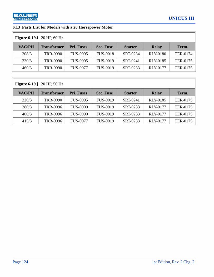
UNICUS III
Page 124 1st Edition, Rev. 2 Chg. 2
6.13 Parts List for Models with a 20 Horsepower Motor
Figure 6-19.i 20 HP, 60 Hz
VAC/PH Transformer Pri. Fuses Sec. Fuse Starter Relay Term.
208/3 TRR-0090 FUS-0095 FUS-0018 SRT-0234 RLY-0180 TER-0174
230/3 TRR-0090 FUS-0095 FUS-0019 SRT-0241 RLY-0185 TER-0175
460/3 TRR-0090 FUS-0077 FUS-0019 SRT-0233 RLY-0177 TER-0175
Figure 6-19.j 20 HP, 50 Hz
VAC/PH Transformer Pri. Fuses Sec. Fuse Starter Relay Term.
220/3 TRR-0090 FUS-0095 FUS-0019 SRT-0241 RLY-0185 TER-0175
380/3 TRR-0096 FUS-0090 FUS-0019 SRT-0233 RLY-0177 TER-0175
400/3 TRR-0096 FUS-0090 FUS-0019 SRT-0233 RLY-0177 TER-0175
415/3 TRR-0096 FUS-0077 FUS-0019 SRT-0233 RLY-0177 TER-0175

MNL-0375
October 22, 2009 Page 125
6.14 Typical Wiring Diagram
For Reference Only

UNICUS III
Page 126 1st Edition, Rev. 2 Chg. 2
CHAPTER 7: CARBON MONOXIDE MONITOR7.1 Description
The Carbon Monoxide (CO) Monitor is a factory installed option which may have been ordered with your unit.
The Carbon Monoxide Monitor, Bauer P/N; MNR-0029, is a standalone assembly, which may be installed on a compressor unit or trailer.(See Figure 7-1).
The Carbon Monoxide Monitor, Bauer P/N; MNR-0033 (See Figure 7-2) appears outwardly identical to MNR-0029 but is designed for use with a remote display, which can be located up to 100 feet from the compressor unit. The Remote Display, Bauer P/N; MNR-0034, is powered by the Carbon Monoxide Monitor, MNR-0033.
• The Carbon Monoxide (CO) Monitor is designed to provide continuous monitoring of the carbon monoxide levels in breathing air.
• The Carbon Monoxide Monitor is enclosed in a NEMA-4X case and operates on 12 VDC or 120 VAC.
Figure 7-1 CO Monitor, MNR-0029 Figure 7-2 Remote Display
1. LCD Display2. Flow Indicator3. Electrical Power Connection4. Front Cover Screw
5. Air Inlet Connection6. Zero Cal Set Switch7. Calibration Port
1. CO Monitor, MNR-00332. Remote Display, MNR-0034
1 2 3
4
5
6
7

MNL-0375
October 22, 2009 Page 127
• Calibration adjustment is performed automatically by the internal microprocessor.
• The Carbon Monoxide Sensor Cell has a life expectancy of one and a half to three years if the calibra-tion check is done every 30 days as recommended.
7.1.1 Component DescriptionThe following are the major components for the standard and trailer Carbon Monoxide Monitor Assem-bly installations. See Figure 7-3.
7.1.1.1 Isolation ValveControls the input of air from the compressor to the Carbon Monoxide Monitor.
7.1.1.2 High Pressure to Low Pressure RegulatorTypically set for 50 psi out with 5,000 psi in.
7.1.1.3 Relief ValveA relief valve which is factory set to 165 psi to prevent over-pressurization of the Carbon Monoxide Monitor.
7.1.1.4 Solenoid ValveAllows air to flow to the Carbon Monoxide Monitor when the compressor is running.
7.1.1.5 Inlet RegulatorA regulator the operator uses to set the appropriate rate of flow (0.5 to 0.8 SCFH) to the Carbon Mon-oxide Monitor.
7.1.1.6 Carbon Monoxide MonitorThe Carbon Monoxide Monitor contains the LCD Display, Flowmeter, Microprocessor, Carbon Mon-oxide Sensor Cell, Air Inlet Connection and the Calibration Port.
7.1.1.6.1 Carbon Monoxide Sensor Cell.The Carbon Monoxide Sensor Cell is an electrochemical element inside the Carbon Monoxide Monitor which senses the amount of Carbon Monoxide in the airstream and produces an analog electrical signal for the control and display functions of the Carbon Monoxide Monitor.
7.1.1.7 Test Gas StorageThis provides a place to keep Calibration Gas bottles so that the Carbon Monoxide Monitor can be cal-ibrated in all situations. Normally these are only found only in trailer installations.
7.2 Carbon Monoxide Monitor SetupThe initial setup of the Carbon Monoxide Monitor is done prior to shipping the unit.
Figure 7-3 Carbon Monoxide Monitor Flow Diagram

UNICUS III
Page 128 1st Edition, Rev. 2 Chg. 2
7.3 Operation
1. Start the compressor unit.
2. The LCD Display will show introductory messages and a warm up countdown (WARM XX).
3. After the warm up countdown of 120 seconds, the instrument will display Carbon Monoxide level readings.
4. The Inlet Regulator may be adjusted at any time to set the flow level from 0.5 to 0.8 SCFH on the Flow Indicator.
5. If the compressor is not running then a LOW FLOW indication will show on the display.
6. If carbon monoxide readings remain high or below zero calibration may be needed.
7.4 Maintenance7.4.1 Calibrating Carbon Monoxide Monitor.
1. Before calibration, be sure that the test gas bottles in the calibration kit have an adequate amount of gas in the them. Attach the fixed flow regulator to the gas bottle and then detach it. You should hear a slight popping sound.
2. Turn on the compressor unit. The compressor itself does not have to run, because the test gas is being substituted for the air supply from the compressor.
3. The compressor unit power needs to be applied to the unit for 15 minutes so the unit can stabilize. If you attempt to calibrate before the end of this 15 minute period, TO SOON will appear on the LCD Display.
4. Lift the cap of Inlet Regulator and turn counterclockwise until it stops. This will ensure that the air flow from the compressor unit is shut off.
5. If the gas flow from the compressor unit was not shut off, a message SUPPLY OFF will appear. If this message appears, shut off the supply air and then begin the calibration process again.
6. Connect the 20 ppm Carbon Monoxide Test Gas to the fixed flow regulator and connect it to the Calibration Port of the Carbon Monoxide Monitor.
7. Turn the value on the Fixed Flow Regulator counterclockwise until the Carbon Monoxide Monitor Flow Indicator shows between 0.5 and 0.8 SCFH.
8. The Display will count down from 60 seconds. At the conclusion, the display will prompt Car-bon Monoxide G SET or CAL FAILED
9. The the display will prompt REMOVE Carbon Monoxide GAS.
10. Turn the valve on the Fixed Flow Regulator clockwise until it is closed and disconnect it from the Calibration Port and disconnect the 20 ppm Carbon Monoxide Test Gas bottle from the fixed flow regulator.
NOTICE
Calibration is recommended every thirty days.
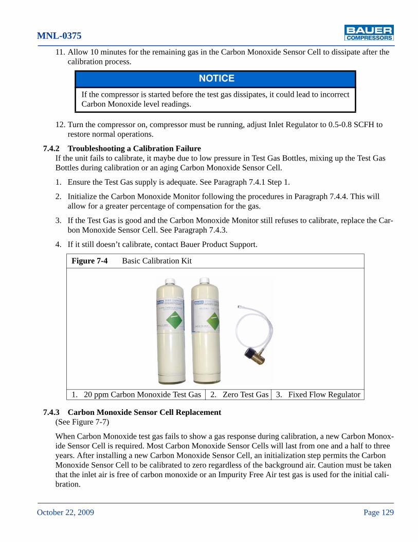
MNL-0375
October 22, 2009 Page 129
11. Allow 10 minutes for the remaining gas in the Carbon Monoxide Sensor Cell to dissipate after the calibration process.
12. Turn the compressor on, compressor must be running, adjust Inlet Regulator to 0.5-0.8 SCFH to restore normal operations.
7.4.2 Troubleshooting a Calibration FailureIf the unit fails to calibrate, it maybe due to low pressure in Test Gas Bottles, mixing up the Test Gas Bottles during calibration or an aging Carbon Monoxide Sensor Cell.
1. Ensure the Test Gas supply is adequate. See Paragraph 7.4.1 Step 1.
2. Initialize the Carbon Monoxide Monitor following the procedures in Paragraph 7.4.4. This will allow for a greater percentage of compensation for the gas.
3. If the Test Gas is good and the Carbon Monoxide Monitor still refuses to calibrate, replace the Car-bon Monoxide Sensor Cell. See Paragraph 7.4.3.
4. If it still doesn’t calibrate, contact Bauer Product Support.
7.4.3 Carbon Monoxide Sensor Cell Replacement(See Figure 7-7)
When Carbon Monoxide test gas fails to show a gas response during calibration, a new Carbon Monox-ide Sensor Cell is required. Most Carbon Monoxide Sensor Cells will last from one and a half to three years. After installing a new Carbon Monoxide Sensor Cell, an initialization step permits the Carbon Monoxide Sensor Cell to be calibrated to zero regardless of the background air. Caution must be taken that the inlet air is free of carbon monoxide or an Impurity Free Air test gas is used for the initial cali-bration.
NOTICE
If the compressor is started before the test gas dissipates, it could lead to incorrect Carbon Monoxide level readings.
Figure 7-4 Basic Calibration Kit
1. 20 ppm Carbon Monoxide Test Gas 2. Zero Test Gas 3. Fixed Flow Regulator

UNICUS III
Page 130 1st Edition, Rev. 2 Chg. 2
1. Disconnect the power from the unit.
2. Remove the four corner screws and open the Carbon Monoxide Monitor front cover.
3. Remove the screws that hold the Carbon Monoxide Sensor Cell cover.
4. Remove the Carbon Monoxide Sensor Cell from its socket by pulling it up from the circuit board.
5. Install a new Carbon Monoxide Sensor Cell.
6. Replace the Carbon Monoxide Sensor Cell Cover, ensuring the longer screw is in its indicated hole.
7. Reassemble the Carbon Monoxide Monitor and reconnect to power.
8. Let the new Carbon Monoxide Sensor Cell warm-up for an hour before doing the Initialization.
9. See Paragraph 7.4.4 for Carbon Monoxide Monitor Initialization procedures.
7.4.4 Carbon Monoxide Monitor InitializationInitialization of the Carbon Monoxide Monitor will need to be done if a calibration fails, the Carbon Monoxide Sensor is replaced or any other maintenance on the internal components of the Carbon Mon-oxide Monitor System was performed.
^ CAUTION
Be sure the power is disconnected from the unit.
^ CAUTION
Be sure the shorting wire is removed from the new Carbon Monoxide Sensor Cell.

MNL-0375
October 22, 2009 Page 131
7.4.4.1 Setting the LP Regulator
See Figure 7-5
1. Attach a Pressure Gauge (0 -100 psi) to the Outlet (1) of the Regulator (3).
2. Apply 5,000 psi to the Regulator (3) using Isolation Valve (2).
3. Loosen Jam Nut (4).
4. Using an Allen wrench turn the regulator adjusting screw (5) until the Pressure Gauge reads 50 psi with an input pressure of 5,00 psi.
5. Tighten Jam Nut (4), Remove Pressure Gauge and reattach Outlet Connection.
7.4.4.2 Initialization Calibration
1. Before calibration, be sure that the test gas bottles in the Calibration Kit (See Figure 7-4) have an adequate amount of gas in the them. Attach the Fixed Flow Regulator to the gas bottle and then detach it. You should hear a slight popping sound.
2. Turn on the compressor unit. The compressor itself does not have to run, because the test gas is being substituted for the air supply from the compressor.
3. The compressor unit power needs to be applied to the unit for 15 minutes so the unit can stabilize. If you attempt to calibrate before the end of this 15 minute period, TO SOON will appear on the LCD Display.
4. Lift the cap of Inlet Regulator (6) and turn counterclockwise until it stops. This will ensure that the air flow from the compressor unit is shut off.
Figure 7-5 Carbon Monoxide Monitor Initialization
1
2
3 4 5

UNICUS III
Page 132 1st Edition, Rev. 2 Chg. 2
5. If the gas flow from the compressor unit was not shut off, a message SUPPLY OFF will appear. If this message appears, shut off the supply air and then begin the calibration process again.
6. Depress the Zero Cal Set Switch on the front of the Carbon Monoxide Monitor with a paper clip for approximately 30 seconds.
7. Connect the Zero Gas bottle to the Fixed Flow Regulator and connect it to the Calibration Port of the Carbon Monoxide Monitor.
8. Turn the valve on the Fixed Flow Regulator counterclockwise until the Carbon Monoxide Monitor Flow Indicator shows between 0.5 and 0.8 SCFH.
9. The Display should read ZERO CAL and will count down from 60 seconds. At the conclusion, the display prompts, REMOVE ZERO GAS.
10. Turn the valve on the Fixed Flow Regulator clockwise until it is closed and disconnect it from the Calibration Port.
11. Disconnect the Zero Gas Bottle and the display will indicate 20 ppm CAL GAS REQUIRED
12. Connect the 20 ppm Carbon Monoxide Test Gas to the Fixed Flow Regulator and connect it to the Calibration Port of the Carbon Monoxide Monitor.
13. Turn the valve on the Fixed Flow Regulator counterclockwise until the Carbon Monoxide Monitor Flow Indicator shows between 0.5 and 0.8 SCFH.
14. The Display will count down from 60 seconds. At the conclusion, the display will prompt to REMOVE Carbon Monoxide GAS.
15. Turn the valve on the Fixed Flow Regulator clockwise until it is closed and disconnect it from the Calibration Port and disconnect the 20 ppm Carbon Monoxide Test Gas Bottle from the Fixed Flow Regulator.
16. Allow 10 minutes for the remaining gas in the Carbon Monoxide Sensor Cell to dissipate after the calibration process.
17. Turn the compressor on, the compressor must be running, adjust Inlet Regulator to 0.5-0.8 SCFH to restore normal operations.
NOTICE
If the compressor is started before the test gas dissipates, it could lead to incorrect Carbon Monoxide level readings.

MNL-0375
October 22, 2009 Page 133
Figure 7-6 Carbon Monoxide Monitor Internal Components
1. Power Connection2. Gas Inlet3. Audible Alarm (not used)4. Remote Display Connection (only MNR-0033)
5. Carbon Monoxide Sensor Cell Cover6. Alarm Connections7. Carbon Monoxide Sensor Cell
1 2 3 4 5 6
7

UNICUS III
Page 134 1st Edition, Rev. 2 Chg. 2
7.4.5 Carbon Monoxide Monitor Test Mode Buttons
Do not adjust factory settings with the setup menu Mode Buttons unless absolutely necessary and by a trained technician. The only reason to access the setup information is to test the alarm relay interface of the control system which simulates the compressor going into an alarm state. The following describes how to access the TEST MODE.
Figure 7-7 Carbon Monoxide Sensor Cell Removal
^ CAUTION
Except for the Carbon Monoxide Sensor Cell, all internal Carbon Monoxide monitor parts are to be serviced only by the manufacturer.
^ CAUTION
Except for testing the Display LCD, adjusting the parameters set at factory incorrectly could be dangerous.Adjustment, if necessary, must be done by a trained technician.

MNL-0375
October 22, 2009 Page 135
1. Unscrew the four large screws on all corners of the Front Cover (See Figure 7-3).
2. Lift the Front Cover carefully, to not harm any of the attached wires inside the Carbon Monoxide monitor.
3. Find the two white mode buttons on the left side of the motherboard (See Figure 7-8). By briefly depressing the top button six times it is possible to cycle through the set up parameters to access the TEST MODE.
4. When TEST MODE is displayed simply depress the bottom Value Change Button. Depressing the Value Change Button sends an input signal to the PLC, shutting down the compressor system and annunciating a high Carbon Monoxide alarm (reference the electrical section of this manual for more information). TEST MODE also sounds the auxiliary horn (if installed) and activates the solid squares on Front Cover LED Readout.
5. The top mode button must be depressed again to return to Normal Mode.
6. Replace Front Cover and screw in place.
7.5 Remote Display Setup
(See Figure 7-9) To calibrate the Remote Display, adjust the internal potentiometer with the compressor system control switched on, so the Carbon Monoxide Monitor will be energized. However do not have
Figure 7-8 Mode Buttons Close-up
1. Mode Scroll Button 2. Value Change Button
NOTICE
The Remote Display must not be installed more than 100 feet from the Carbon Monoxide Monitor.
1
2

UNICUS III
Page 136 1st Edition, Rev. 2 Chg. 2
the compressor running, because the air supply from the compressor is unnecessary for the Remote Dis-play setup.
1. To calibrate the Remote Display unit during normal operation of the compressor unit, make sure the that both the compressor and Carbon Monoxide Monitor units are on.
2. Open the Remote Display (See Figure 7-9). Find the top potentiometer and adjust it to match the Carbon Monoxide Monitor Carbon Monoxide display reading. Notice that the Carbon Monoxide Monitor rounds off to whole numbers while the Remote Relay displays decimal places, so adjust as close as possible.
3. When the display readings match, reassemble the Remote Relay. Realign readings if necessary.
Figure 7-9 Remote Display
1. Remote Display Calibration Screw

MNL-0375
October 22, 2009 Page 137
7.6 Replacement Parts List
Item Qty Part No. Description Notes♦ ASY-0890 Carbon Monoxide Monitor Assembly1 1 MNR-0029 Carbon Monoxide Monitor2 1 VAL-0076 Isolation Valve3 1 REG-0043 High - Low Pressure Regulator4 1 VAL-0432 Safety Valve 145 psi5 1 VAL-0348 Solenoid Valve 115 VAC— 1 VAL-0349 Solenoid Valve 12 VDC6 1 REG-0060 Inlet Regulator N.S. 1 SEN-0025 Carbon Monoxide Sensor CellN.S. 1 CYL-0020 Zero Gas Cylinder 0 ppmN.S. 1 CYL-0016 Carbon Monoxide Test Gas Cylinder 20 ppm
Figure 7-10 Carbon Monoxide Monitor Assembly - Standard
1
2
3 4 5
6

UNICUS III
Page 138 1st Edition, Rev. 2 Chg. 2
Figure 7-11 Carbon Monoxide Monitor Schematic
RED
RED
No
Con
nect
ion.
No Connection
No
Con
nect
ion.
+– 1
1
1
RECORDEROUTPUT
120
VA
C
CONNECTS TOCOMPRESSORCONTROLS
INCOMINGPOWER
DP
+.
DP
-.
NO
.
CO
M.
NC
.
NO
.N
ot U
sed.
Not
Use
d.N
ot U
sed.
CO
M.
NC
.
REDRELAY
YELLOWRELAY
CONNECTS TOCOMPRESSORCONTROLS
TOREMOTEDISPLAY BOARD
WHT/BLK
CO MonitorMNR-0029/MNR-0033
Jumper
1702
-113
BP
OW
ER
BO
AR
D
GN
D.
AC
1.
AC
2.
INT
PW
R.
+24
VD
C.
EXT. 12V OPER.
TRANSFORMER
MAX 18 AWG WIRE
+ – + – + –PWR SIG B/L
N/AN/ADisplay Adjustment Pot.
Remote Display BoardMNR-0034
REMOVE JUMPER12V OPERATION
GND.
12V
INT. 24V OPER
No
Con
nect
ion.
DP
+.
DP
-.
A
A
MNL-0375
October 22, 2009 Page 139
CHAPTER 8: CFS II MAINTENANCE8.1 Description
The UNICUS III containment fill stations are designed and have been tested to offer the operator protec-tion against the explosive force and resulting shrapnel should a cylinder fail during the filling operation.
The fill station features fill hoses complete with bleed valves and SCBA fill adapters of choice, mechani-cal door interlock, and a fill control panel with individual pressure gauges.
8.2 Fill Station Air Flow Refer to the Pneumatic Diagram DGM-1137, after the Appendix.
From the air inlet, compressed air flows to the Fill Pressure Regulator (R1) where the desired bottle fill pressure is set and maintained. The Regulator Inlet Pressure Gauge (P1) indicates the supply pressure to the Regulator (R1). The Regulator Outlet Pressure Gauge (P2) indicates this regulated pressure. The Fill Pressure Relief Valve (RV1) ensures against overfilling the bottle if the Fill Pressure Regulator (R1) fails.
The Door Interlock Valves (V1) are operated when the door is closed and the lock bar is in the down and locked position. This prevents the filling of bottles until the door is properly closed and locked.
When the Mechanical Door Interlock Valves (V1) are operated it allows compressed air to flow from the outlet of the Fill Pressure Regulator (R1) to the Fill Hoses (H1) via the Fill Hose Shut Off Valve (V2).
Fill Pressure Gauge (P3) is used to monitor the progress of the recharging operation.
The operator closes the Fill Hose Shut Off Valve (V2) when the bottle reaches the desired pressure, stop-ping the flow of air to the bottle.
The optional Fill Pressure Relief Valves (RV2) can be used to allow multiple fill pressures in the same CFS II.
Should the operator not close the Fill Hose Shut Off Valve (V2) when the bottle is full, the Relief Valve (RV2) will open, venting excess pressure.
When the recharging operation is complete the operator presses down on the Door Handle and opens the door which disengages the Mechanical Door Interlock Valves (V1) eliminating the possibility of the flow of compressed air to the bottles.
Before the bottles can be removed from the fill station the bottle valve must be closed and the pressure remaining in the Fill Hoses (H1) bled off by opening the Drain/Bleed Valve (V3).
8.3 Maintenance
8.3.1 General MaintenanceDevelop a regular program of visual inspection, looking for clogged drains and broken or missing parts.
^ WARNING
If a cylinder fails during a filling operation, the Containment Fill Station must be considered damaged beyond repair and destroyed to prevent its ever being used again.

UNICUS III
Page 140 1st Edition, Rev. 2 Chg. 2
8.3.2 Nonadjustable ValvesThe condensate drain valve, bleed valve and check valves are not adjustable. The condensate drain valve and bleed valve have seats and seals which should be replaced if the valve leaks. Check valves are not adjustable or repairable and must be replaced if they malfunction.
8.3.3 Pressure GaugesObserve the pressure gauges daily. If the readings of any of the gauges seem to be incorrect, bleed off all system pressure. Check that the gauges correctly read zero then reapply pressure to the system. If the reading is still incorrect contact Bauer Compressors for service. All broken or damaged gauges must be replaced immediately.
8.3.4 Safety Valves
The safety valve must be checked periodically for proper functioning.
1. Operate the compressor with the shut-off valve closed until the safety valve vents.
2. Note the pressure registered on the pressure gauge.The safety valve is adjusted at the factory to the required pressure and does not normally require mainte-nance or readjustment. In case readjustment does become necessary, have the safety valve adjusted by a Bauer qualified technician (contact the Bauer service department for details) or return the valve to the factory.
8.3.5 Pneumatic Connections
After determining that a pneumatic connection is leaking. Relieve compressed air pressure and tighten just firmly enough so that leakage is stopped (finger tight plus up to an additional ½ turn as necessary). Please note that the compression type coupling fittings are capable of exerting extreme force on the tub-ing and should not be tightened more than is required to seal the joint. To improve the sealing of the pipe connections and to facilitate installation, the following should be observed:
Figure 8-1 Safety Valves
^ WARNING
Maintenance of pipe and tubing connections should not be attempted while the unit is under pressure. Serious injury or equipment damage will result if the connection fails or is loosened.

MNL-0375
October 22, 2009 Page 141
Apply a thin layer of Never-Seez® NSWT or equivalent on the outside of the ferrule during assembly.
Lubricate the threads of the connector with Never-Seez® NSWT or a similar PFTE base lubricant to facil-itate future disassembly.
8.3.6 Bearings for Bottle Door PivotThere is no need for relubrication under normal conditions.
If the setscrews should become loose, tighten as follows:
8.3.7 Pressure HosesThe hoses should be inspected periodically for wear and damage. If a hose is worn or damaged, remove and replace it.
8.3.8 Door Gas SpringA special tool, Spring Holder, TOO-0020 is required.
To remove and install a Door Gas Spring proceed as follows:
1. Place a piece of cardboard in the bottom of the door opening to protect the finish of the Door and Enclosure.
2. Remove the Door Stop and Mount from the inside rear of the Enclosure.
3. Lower the Door until it touches the cardboard.
4. Install the Spring Holder, TOO-0020 and raise the Door until the Holder is holding the Door Gas Spring.
5. Remove the nut on the lower mounting stud and remove the Door Gas Spring from the Door.
6. Lower the Door and allow it to rest on the cardboard.
7. Remove the nut on the upper spring mounting stud and remove the Door Gas Spring.
8. Install the replacement Door Gas Spring in the reverse order.
Setscrew diameter Hex size Recommended torque (inch lbs)
5/16” 5/32” 165
Figure 8-2 Special Tool, TOO-0020

UNICUS III
Page 142 1st Edition, Rev. 2 Chg. 2
8.4 Replacement Parts List
8.4.1 CFS II Assemblies
Item Qty Part No. Description Notes1 3 HOL-0076 Bottle Holder2 1 DOR-0002 Door3 3 HOS-0145 Fill Whip4 1 HAN-0057 HandleN.S. 1 SPC-0008 Bottle Riser 1 per Fill Position
Figure 8-3 CFS II Assembly
1
2
3
4

MNL-0375
October 22, 2009 Page 143
Item Qty Part No. Description Notes1 1 LCH-0049 Door Lock 3 Fill Positions2 3 BUS-0120 Bushing3 2 CYL-0059 Damper4 1 BRK-0487 Cylinder Bracket Right— 1 BRK-0486 Cylinder Bracket Left
Figure 8-4 CFS II Door Lock Assembly
12
23
4

UNICUS III
Page 144 1st Edition, Rev. 2 Chg. 2
Item Qty Part No. Description Notes1 1 MTS-0314 Mount2 1 VIB-0035 Bumper3 2 PIN-0047 Pin4 2 BUS-0121 Bushing5 2 CLR-0001 Collar
Figure 8-5 Door Handle, Pivot and Bracket
1
2
3
4
5
6
7
8
9
1011

MNL-0375
October 22, 2009 Page 145
Figure 8-5 (cont.) Door Handle, Pivot and Bracket
Item Qty Part No. Description Notes6 2 … Flat Head Socket Cap Screw 5/16 x 18 x ¾” UNC7 2 … Socket Head Cap Screw 3/8-16 x 1” UNC8 2 … Socket Head Cap Screw 3/8-16 x 2” UNC9 2 … Washer, Nylon 5/8”10 2 BUS-0122 Bushing11 1 SPG-0054 Spring Right Side— 1 SPG-0053 Spring Left Side

UNICUS III
Page 146 1st Edition, Rev. 2 Chg. 2
Item Qty Part No. Description Notes1 2 LCH-0048 Latch2 2 SPG-0052 Torsion Spring3 2 … Socket Head Shoulder Screw 3/8” x 7/8”4 6 … Nylon Flat Washer 3/8”
Figure 8-6 CFS II Door Lock Latch
1
2
3
4

MNL-0375
October 22, 2009 Page 147
Item Qty Part No. Description Notes1 2 VAL-0130 Interlock Valve2 1 BRK-0488 Bracket3 2 LEV-0018 Lever4 1 HOS-0147 Hose 1st Fill Position5 2 HOS-0146 Hose 2nd and 3rd Fill Positions6 1 SCR-0078 Hex Head Cap Screw ¼-20 x 4” UNC7 1 SPG-0056 Gas Spring8 2 LCH-0048 Latch See Figure 8-69 1 LCH-0049 Latch See Figure 8-410 2 CYL-0059 Damper See Figure 8-411 1 … Hex Head Cap Screw ¼-20 x 4½” UNC
Figure 8-7 CFS II Door Interlock

UNICUS III
Page 148 1st Edition, Rev. 2 Chg. 2
8.4.2 Fill Hose Assemblies
Item Qty Part No. Description Notes1 1 HOS-0145 Fill Hose2 1 065126 Bleed Valve3 2 ELL-0018 Elbow4 1 ADP-0112 Adapter 4,500 / 2,216 psi Cylinder— 1 ADP-0113 Adapter 4,500 psi Cylinder5 1 YOK-0001 Fill Yoke6 1 TEE-0012 Tee7 1 VAL-0169 Safety Valve8 1 N04483 O-ring
Figure 8-8 Standard Fill Hose Assembly
Relief OptionRelief Option
6
7 1
2
3
4
5
3
8

MNL-0375
October 22, 2009 Page 149
Item Qty Part No. Description Notes1 1 YOK-0001 Fill Yoke2 3 ELL-0018 Elbow3 1 ADP-0112 Adapter 4,500 / 2,216 psi Cylinder— 1 ADP-0113 Adapter 4,500 psi Cylinder4 1 065126 Bleed Valve5 1 HOS-0145 Fill Hose6 2 CON-0223 Quick Disconnect Plug7 1 TEE-0014 Tee8 1 VAL-0169 Safety Valve9 1 N04483 O-ring
Figure 8-9 Multi Fill Hose Assembly
Relief OptionRelief Option
4
2
3
9
2
1
5
6
78
6
2

UNICUS III
Page 150 1st Edition, Rev. 2 Chg. 2
CHAPTER 9: UNICUS III HP AIR STORAGE9.1 Bottle Specifications
Storage systems are available to meet the code requirements of either the Department of Transportation or the American Society of Mechanical Engineers. Operating temperature range for storage systems is - 20° F to 150° F. To - 40° F is an available option.
9.1.1 D.O.T. Department of TransportationThese vessels are approved by the Department of Transportation. The cylinders must be equipped with the proper cylinder valve and CGA recommended outlet. Retest period for D.O.T. 5000 and 6000 psig cylinders is mandatory every five (5) years in accordance with 49/CFR173.34.
Bauer can supply 5000 psig and 6000 psig D.O.T. systems complete with interpiping, pressure gauges, cylinder valves and check valve. Optional mounting racks are available.
9.1.2 A.S.M.E. American Society of Mechanical EngineersEach vessel should have a shut-off valve and an A.S.M.E. approved safety valve. Vessels with working pressures of 5000 psig, have a safety factor of 4 to 1. Vessels with working pressures of 6000 psig, have a safety factor of 3 to 1. Bauer can supply 5000 psig and 6000 psig A.S.M.E. storage systems complete with interpiping, pressure gauges, safety valves, cylinder valves and check valves. Optional mounting racks are available.
VesselD.O.T AMSE
5,000 psig 6,000 psig 5250 psig 6,600 psig
Material Lightweight Steel Alloy Steel ASME SA 372 Class V Type A AISI 4130
Volume 471 cf @ 5000 psig 509 cf @ 6000 psig 424 cf @ 5,000 psig 481 cf @ 6,000 psig
WorkingPressure 5,000 psig 6,000 psig 5,000 psig 6,000 psig
TestPressure 7,500 psig 9,000 psig 7,875 psig 10,500 psig
Diameter 9 3/8” 9 9/32” 9 5/8” 9 5/8”
Height 55” with Valve 55” without Valve
Weight 158 lbs 188 lbs 400 lbs
Cylinder CGA 347 CGA 702 Standard Valve Supplied
Finish Primer and Topcoat Primer and Topcoat

MNL-0375
October 22, 2009 Page 151
9.2 Description and Maintenance
9.2.1 DescriptionThe air storage system consists of one (or more) D.O.T. or A.S.M.E. storage vessels with line valves, safety valves, interconnecting tubing, pressure gauges, check valves and mounting clamps.
D.O.T. vessels are approved by the Department of Transportation for portable usage. D.O.T. systems are available at 5,000 psi and 6000 psi.
A.S.M.E. vessels conform to the American Society of Mechanical Engineers codes for permanent instal-lation. These vessels have working pressures of 5000 psig, with a safety factor of 4 to 1; and 6000 psig, with a safety factor of 3 to 1. A safety device is provided on each vessel to protect against excess pres-sure. It is preset at the factory and sealed. It should not be adjusted.
Figure 9-1 UNICUS III Storage System

UNICUS III
Page 152 1st Edition, Rev. 2 Chg. 2
9.2.2 Maintenance
9.2.2.1 Storage BottlesAll storage bottles should be visually inspected internally every year. Every five (5) years, D.O.T. bottles must be hydrotested.
Check local and state regulations regarding testing of ASME or D.O.T. bottles. Some states require an annual visual inspection, and hydrotesting requirements also differ from state to state.
9.2.2.2 Pressure Gauges
1. Observe the pressure gauges daily.
2. If the readings of any of the gauges seem to be incorrect, bleed off all system pressure.
3. Then, remove the gauge and check for wear and tear, accuracy and proper functioning by compar-ing it to a precision test gauge or a dead weight tester.
4. Replace all broken or damaged gauges immediately.
9.2.2.3 Tube ConnectionsPipe connections (swivel nuts): Tighten just firmly enough so that leakage is stopped (finger tight plus up to an additional ½ turn as necessary). Please note that the compression type coupling fittings are capable of exerting extreme force on the tubing and should not be tightened more than is required to seal the joint.
To improve the sealing of the pipe connections and to facilitate installation apply a thin layer of Never-Seez® NSWT or a similar PFTE base lubricant to the ferrule and the threads of the connector to facilitate future disassembly.

MNL-0375
October 22, 2009 Page 153
9.2.2.4 Safety Valve
• Develop a regular program of visual inspection, looking for clogged drains and discharge pipe, dirt build-up in and around the valve seat, and broken or missing parts.
• Avoid excessive operation of the safety valve, as even one opening can provide a means for leakage. Safety valves should be operated only often enough to assure that they are in good working order.
• Do not paint, oil or otherwise cover any interior or working parts of any safety valve. They do not require any lubrication or protective coating to work properly.
9.2.2.5 Pressure HosesThe hoses should be inspected periodically for wear and damage. If a hose is worn or damaged, remove and replace it.
Figure 9-2 Safety Valve

UNICUS III
Page 154 1st Edition, Rev. 2 Chg. 2
CHAPTER 10: CONTROLS AND INDICATORS10.1 Component Locations
Figure 10-1 Front Panel
1. Cascade Panel Pressure Gauges2. Cascade Panel Valves3. Fill Selector Valve4. Fill Pressure Gauge5. Regulator Valve
6. Compressor Final Pressure Gauge7. Compressor Control Panel8. Emergency Stop Switch9. Bottle Fill Valves10. Bottle Fill Pressure Gauges
1
2
3
4 5 6
78
9
10

MNL-0375
October 22, 2009 Page 155
Figure 10-2 Gauge Panel
1. Compressor Oil Pressure Gauge2. 1st Stage Pressure
3. 2nd Stage Pressure4. 3rd Stage Pressure
1
2
3
4

UNICUS III
Page 156 1st Edition, Rev. 2 Chg. 2
Figure 10-3 Components for Remote Fill Option
1. Remote Fill Regulator2. Remote Fill Pressure Gauge3. Remote Fill Valve
4. Storage Drain Valves5. Hose Guide6. Hose Stop
7. Hose8. Bleed Valve9. Hose Reel
1
2
3
4
5
6
7
8
9

MNL-0375
October 22, 2009 Page 157
10. Replacement Parts List
Item Qty Part No. Description Notes1 6 VAL-0076 Needle Valve2 9 GAG-0009W Pressure Gauge 7,500 psi3 1 VAL-0067 3-way Ball Valve4 1 REG-0039 Air Pressure Regulator 6,000 psi5 1 MNR-0049 Compressor Control Panel Maple System, Touch Screen6 1 SWT-0244 E-stop Switch
Figure 10-4 Front Panel Parts
1 2 3
4 5 6

UNICUS III
Page 158 1st Edition, Rev. 2 Chg. 2
Item Qty Part No. Description Notes1 1 GAG-0042W 2.5” Indicator 0 - 100 psi2 1 GAG-0006W 2.5” Indicator 0 - 200 psi3 1 GAG-0007W 2.5” Indicator 0 - 600 psi4 2 GAG-0008W 2.5” Indicator 0 - 1500 psi
Figure 10-5 Gauge Panel Parts
1
2
3
4

MNL-0375
October 22, 2009 Page 159
Item Qty Part No. Description Notes1 1 REG-0039 Air Pressure Regulator 6,000 psi2 1 GAG-0009W Pressure Gauge 7,500 psi3 5 VAL-0076 Needle Valve4 1 GDE-0003 Hose Guide5 1 STP-0008 Hose Stop6 1 HOS-0164 Air Hose 75 feet7 1 VAL -0140 Bleed Valve8 1 REL-0009 Hose Reel 75 feet maximum
Figure 10-6 Remote Fill Option Parts
1
2
3
4

UNICUS III
Page 160 1st Edition, Rev. 2 Chg. 2
CHAPTER 11: APPENDIX11.1 Safety
11.1.1 General Safety Precautions• Read the operating manual before installing or operating this compressor unit. Follow appropriate
handling, operation and maintenance procedures from the very beginning. The maintenance schedule contains measures required to keep this compressor unit in good condition. Maintenance is simple, but must be executed regularly to achieve safe operation, maximum efficiency and long service life.
• We recommend that all maintenance work be recorded in a service book, showing the date and details of the work carried out. This will help to avoid expensive repairs caused by missed maintenance work. If it is necessary to make a claim against the warranty, it will help to have proof that regular maintenance has been carried out and that the damage has not been caused by insufficient mainte-nance.
• This compressor unit must be installed, operated, maintained and repaired only by authorized, trained and qualified personnel.
• Consult and follow all OSHA, NEMA, ASME and local regulations, laws and codes covering the installation and operation of this compressor and accessories before operating the unit.
• Do not operate this unit in excess of its rated capacity, speed, pressure, temperature, or otherwise than in accordance with the instructions contained in this manual. Operation of this unit in excess of the conditions set forth in this manual will subject the unit to limits which it may not be designed to with-stand.
• Keep safety guards in place.
• Do not modify the compressor or its systems.
• Do not wear loose clothing around machinery. Loose clothing, neckties, rings, wrists watches, brace-lets, hand rags, etc. are potential hazards.
• Provide adequate fire protection. Make sure fire extinguishers are accessible. Select alternate routes of escape and post such routes.
• Make sure you are equipped with all required safety equipment; hearing protection, safety glasses, hard hats, safety shoes and fire extinguisher.
• Visually inspect the unit before starting. Remove and/or replace any loose or broken components, tools, valves, missing equipment, etc.
• Do not tamper with, modify, or bypass safety and shutdown equipment.
• Do not tighten or adjust fitting or connections under pressure.
• The use of plastic pipe or rubber hose in place of steel tube or iron pipe, soldered joints or failure to ensure system compatibility of flex joints and flexible hose can result in mechanical failure, property damage, and serious injury or death.
• The use of plastic or nonmetallic bowls on line filters without metal guards can be dangerous.
• Replace damaged fan blades promptly. Fan assemblies must remain in proper balance. An unbalanced fan can fly apart and create an extremely dangerous condition.

MNL-0375
October 22, 2009 Page 161
• Allow the compressor to cool before servicing. Whenever the compressor is shut down and over-heating is suspected, a minimum period of 15 minutes must elapse before opening the crankcase. Premature opening of the crankcase of an overheated unit can result in an explosion.
• Incorrect placement of the inlet and pressure valves in a compressor cylinder head can cause an extremely dangerous condition. Refer to the appropriate section of this manual before installing or replacing valves.
• Before doing any work involving maintenance or adjustment, be sure the electrical supply has been disconnected, and the complete compressor system has been vented of all internal pressure. Failure to follow these warnings may result in an accident causing personal injury and/or property damage.
• Before working on the electrical system, be sure to disconnect the electrical supply from the system at the circuit breaker or other manual disconnect. Do not rely on the ON/OFF switch to disconnect the electrical supply.
• Installer must provide an earth ground and maintain proper clearance for all electrical components.
• All electrical installation must be in accordance with recognized national, state, and local electrical codes.
• Do not use gasoline, diesel fuel or other flammable products as a cleaning solution.
• A compressor which has been used for gas service is unsuitable for air applications. Should the purchaser and/or user proceed to use the compressor for air service after it has been used for gas, the purchaser and/or user assumes all liability resulting therefrom without any responsibility being assumed by Bauer Compressors, Inc. The purchaser is urged to include the above provision in any agreement for resale of this compressor.
• The use of repair parts other than those listed in this manual or purchased from Bauer Compressors, Inc. may create unsafe conditions over which Bauer has no control. Such unsafe conditions can lead to accidents that may be life-threatening, cause substantial bodily injury, and/or result in damage to the equipment. Therefore, Bauer Compressors, Inc. can bear no responsibility for equipment in which non-approved repair parts are installed

UNICUS III
Page 162 1st Edition, Rev. 2 Chg. 2
11.1.2 Safety Warning LabelsNotes, labels and warning signs are displayed on the compressor unit according to model, application or equipment and may include any of the following.
HOT SURFACES DO NOT TOUCH!Danger of burning if cylinders, cylinder heads, or pressure lines of individual
compressor stages are touched.
HIGH VOLTAGE!Life threatening danger of electrical shock. Maintenance work on electric units or operating equipment should be carried out by a qualified electrician or by a person supervised by a qualified electrician according to electrical regulations.
AUTOMATIC COMPRESSOR CONTROLUNIT MAY START WITHOUT WARNING!
Before carrying out maintenance and repair work, switch off at the main switch and ensure the unit will not restart.
THE INSTRUCTIONS MUST BE READ BEFORE OPERATING UNIT!The instruction manual and all other applicable instructions, regulations, etc.
must be read and understood by the operating personnel before using the machine.
HEARING PROTECTION MUST BE WORN!Hearing protectors must be worn when working on a machine which is running.
DIRECTION OF ROTATION!When switching on the machine, check the arrow to ensure correct direction of
rotation by the drive motor.

MNL-0375
October 22, 2009 Page 163
11.2 Unpacking, Handling and Installation
11.2.1 Unpacking and HandlingThis compressor unit is packaged according to the requirements for shipping via the requested type of carrier service. It is possible that the compressor unit could have been damaged during shipping. For this reason, we urge you to thoroughly examine the unit for possible damage and report any such damage to the shipping company immediately.
Care must be taken in unpacking the compressor unit. Serious damage could result by not checking for clearance between the item being unpacked and the packaging to be removed.
Handling of the unpacked unit should be performed using only the following devices. See Figure 11-1.
The compressor unit may be furnished with one or more shipping braces for shipping and handling only. After installation and before operation, these braces must be removed entirely. Under no circumstances should the braces remain installed during operation or the manufacturer’s warranty for the compressor unit will be voided. The braces are all tagged and labeled.
Figure 11-1 Lifting Devices
1. Forklift 2. Chain Hoist 3. Hand Truck
^ WARNING
Be sure the lifting devices are capable of handling the weight of the unit (see Paragraph 1.4 for the weight of the unit). Before lifting the unit, secure all loose or swinging parts to keep them from moving.
Stay clear of lifted load.
Fork Lift Hand Truck
Chain Hoist

UNICUS III
Page 164 1st Edition, Rev. 2 Chg. 2
11.2.2 Installation of the Compressor UnitThe floor of the site must be capable of supporting the weight of the unit. Position the unit so that it is level. The maximum permissible inclination of the compressor unit is listed in Paragraph 1.4.
Ensure that the compressor air intake is supplied with fresh air. The intake air must not contain any exhaust fumes or flammable vapors such as paint solvents, which may cause an internal fire. Make sure that the intake air is unobstructed and moisture in the intake air is kept to a minimum. It is important that units draw in clean air. The quality of the incoming air determines the quality of the compressed air. This is important even for industrial air, as any incoming fumes will also be compressed and will increase the toxicity to anyone working with the compressed air.
If a remote control is provided, the unit must be equipped with a clearly visible plate warning the possi-bility of the unit starting. As an additional measure, anyone starting the unit by remote control must make sure that no one is checking or operating the unit. For this purpose, a second warning plate should be pro-vided at the remote control unit.
Observe and maintain an ambient temperature range of 43° to 113° F.
The area in which the compressor unit is installed should be well lit and easily accessible to facilitate ser-vicing and routine maintenance.
^ CAUTION
The inclination values listed in Paragraph 1.4 are valid only if the oil level of the compressor is level with but does not exceed the upper mark of the oil dipstick or oil level sight glass
AUTOMATIC COMPRESSOR CONTROLUNIT MAY START WITHOUT WARNING!
Before carrying out maintenance and repair work, switch off at the main switch and ensure the unit will not restart.

MNL-0375
October 22, 2009 Page 165
11.2.2.1 Securing and Leveling the UNICUS III
Secure the UNICUS III to the floor using ½” bolts. The feet at the ends of the unit are used for leveling and securing the UNICUS III, the middle feet are for leveling only. Install the Adjusting Bolts (1) and Locking Nuts (2) until the Leveling Foot (3) can be attached. Adjust the all of the Adjusting Bolts until the Leveling Foot touches the ground and the UNICUS III is level. The Anchor Foot is then positioned as desired and the appropriate anchor hardware installed. The Locking Nuts are then tightened to prevent the Leveling Foot from moving.
11.2.2.2 VentilationDuring normal compression, heat is generated by the compressor and by the drive motor or engine. For air-cooled compressor units, this heat needs to be vented away by sufficient ventilation.
11.2.2.2.1Outdoor InstallationIt is recommended that all gasoline and diesel engine driven compressor units be installed outdoors. Additionally, electrically driven compressor units may be installed outdoors only if enclosed with weath-erproof enclosure panels.
11.2.2.2.2Indoor InstallationThe best location to install the compressor unit indoors is against an outside wall with a suitably large air vent in front of the cooling fan. Additionally, it is necessary to position an exhaust opening in the oppo-site wall, close to the ceiling or in the ceiling.
As a basic rule of thumb, the room should be ventilated sufficiently so as to prevent the ambient room temperature from exceeding 105° F. Additional heat generating equipment or piping should be avoided or must be well insulated.
Figure 11-2 Securing and Leveling the UNICUS III
1. Adjusting Bolt2. Locking Nut
3. Leveling Foot4. Anchoring Foot
1
2
3
4

UNICUS III
Page 166 1st Edition, Rev. 2 Chg. 2
11.2.2.2.3Natural VentilationNatural ventilation should only be used up to a maximum drive power of 20 hp. To determine the size of the required intake and exhaust openings, refer to the following table: .
11.2.2.2.4Forced VentilationTo determine the required intake opening and exhaust flow refer to the following table:
Drive Hp
Intake and Exhaust Openings Dependent on Room Volume (V) and Height (h)
V = 1750 ft³ h = 6.5 ft V = 3500 ft³ h = 10 ft V = 7000 ft³ h = 13 ft
Intake (ft²) Exhaust (ft²) Intake (ft²) Exhaust (ft²) Intake (ft²) Exhaust (ft²)
3 1.3 1.1 --- --- --- ---
5 3.2 2.7 1.3 1.1 --- ---
7.5 4.5 3.8 2.6 2.2 1.3 1.1
10 9.7 8.1 6.5 5.4 2.6 2.2
15 14.5 12.4 9.7 8.1 5.8 4.8
20 20.6 17.2 15.6 12.9 9.7 8.1
Drive Hp
Dependence on Room Size (V) and Height of Exhaust Opening (h)a
a. The intake sizes given in the above table are for a cooling air velocity of 1000 ft./min. Bauer recommends that the cooling air velocity be in the range of 600 ft./min. to 2000 ft./min.
V = 1750 ft³ h = 8 ft V = 3500 ft³ h = 10 ft V = 7000 ft³ h = 13 ft
Intake (ft²)
Exhaust cfm
Intake (ft²)
Exhaust cfm
Intake (ft²)
Exhaust cfm
25 3.3 3300 3.2 3200 3.0 3000
30 4.0 3960 3.8 3840 3.6 3600
40 5.3 5280 5.1 5120 4.8 4800
50 6.6 6600 6.4 6400 6.0 6000
60 7.9 7920 7.7 7680 7.2 7200
75 9.9 9900 9.6 9600 9.0 9000
100 13.2 13200 12.8 12800 12.0 12000
125 16.5 16500 16.0 16000 15.0 15000
150 19.8 19800 19.2 19200 18.0 18000

MNL-0375
October 22, 2009 Page 167
11.2.2.3 Electrical Installation11.2.2.3.1Electric Drive
When making the electrical connections to the system, the following instructions are mandatory:
• Comply with all local, state and federal regulations concerning electrical installation.
• Arrange for the electrical connections to be made by a certified electrician only.
• Ensure that the motor voltage, control unit voltage, and frequency conform with the main voltage and frequency. Do not connect the compressor unit to a voltage other than the one specified on the name-plate.
• Provide all necessary cables and main fuses and a master disconnect switch. The fuse protection for the compressor must be carried out in compliance with local, state and national electrical regulations.
11.2.2.3.2Electrical SupplyThe machine is factory wired according to order. If the voltage is to be changed, consult the factory for instructions and necessary parts.
For standard models the only customer wiring necessary is from the customer supplied disconnect switch to the compressor unit electrical enclosures All wiring should be done by a licensed electrician familiar with national, state and local electrical codes.
The label shown in Figure 11-3 indicates the where the incoming power is connected to the compressor unit electrical enclosure. This label must be removed before using the equipment.
Figure 11-3 Incoming Power Wiring Label

UNICUS III
Page 168 1st Edition, Rev. 2 Chg. 2
The use of improperly sized wire can result in sluggish operation, unnecessary tripping of overload relays and/or blowing of fuses. The following tables are provided as a guide for proper wire size.
1 PHASE
MotorHp
Full Load Amps Fuse Ampsa
a. Dual element time delay fuse Amps.
Minimum Wire Sizeb
b. Normal Copper wire with THW, THWN, or XHHW insulation.
120 V 208 V 230 V 120 V 208 V 230 V 120 V 208 V 230 V
2 24 13.2 12 30 20 17.5 10 --- 14
3 34 18.7 17 50 30 25 8 10 10
5 56 30.8 28 80 50 40 4 8 8
7.5 80 44 40 100 70 60 3 8 8
10 --- 55 50 --- 90 60 --- 6 6

MNL-0375
October 22, 2009 Page 169
In the above tables, all values are based on 1996 NEC articles 430 and 310 (NFPA 70). These values are provided as a general guide; however, the information given on the motor nameplate supersedes the above information.
3 PHASE
MotorHp
Full Load Amps Fuse Ampsa
a. Dual element time delay fuse Amps.
Minimum Wire Sizeb
b. Normal Copper wire with THW, THWN or XHHW insulation.
208 V 230 V 460V 208 V 230 V 460V 208 V 230 V 460V
2 7.5 6.8 3.4 12 10 5.6 14 14 14
3 10.6 9.6 4.8 17.5 15 8 14 14 14
5 16.7 15.2 7.6 25 25 12 10 12 14
7.5 24.2 22 11 40 30 17.5 8 10 14
10 30.8 28 14 50 40 20 8 8 12
15 46.2 42 21 60 60 30 6 6 10
20 59.4 54 27 90 80 40 4 4 8
25 74.8 68 34 100 100 50 3 4 8
30 88 80 40 125 100 60 2 3 8
40 114 104 52 175 150 80 0 1 6
50 143 130 65 200 200 100 3/0 2/0 4
60 169 154 77 250 200 100 4/0 3/0 3
75 211.2 192 96 300 300 150 300 250 1
100 273 248 124 400 350 175 500 350 2/0
125 343.2 312 156 500 400 200 2-4/0 2-3/0 3/0
150 396 360 180 600 500 250 2-300 2-4/0 4/0

UNICUS III
Page 170 1st Edition, Rev. 2 Chg. 2
11.3 Long Term Storage
11.3.1 GeneralIf the compressor unit will be out of service for more than six months, it should be preserved in accor-dance with the following instructions:
1. Make sure that the compressor is kept indoors in a dry, dust-free room.
2. Cover the compressor with plastic sheets only if no condensation will form under the sheet.
3. Remove the sheet from time to time and clean the outside of the unit.
4. If this procedure cannot be followed, or if the compressor will be out of service for more than 24 months, please contact the Bauer Service Department for special instructions.
11.3.2 PreparationsPrior to preserving the compressor unit, it must be run until warm, i.e., up to the specified service pres-sure. Operate the unit for approximately 10 minutes, then carry out the following checks.
1. Check all pipes, filters and valves (including safety valves) for leakage.
2. Tighten all couplings, as required.
3. After 10 minutes, open the outlet valve and operate the compressor at adjusted minimum pressure using the pressure maintaining valve for approximately 5 minutes.
4. After the 5 minutes, shut the compressor unit down and completely drain all separators and filters. Close all valves.
5. Remove filter heads and lubricate the threads with petroleum jelly.
11.3.2.1 Units Equipped with a Filter System
1. Ensure that cartridges remain in the purification system chambers. This will prevent oil from enter-ing the outlet lines as a result of preservation procedures.
2. Remove the intake filter/intake pipe completely.
11.3.3 Preserving the Compressor
1. Operate the compressor again and slowly spray approximately 0.35 oz. (10 cc) of oil into the inlet port while the compressor is running. Keep the shut-off valve open and the condensate drain valves closed.
2. After spraying the oil into the inlet port, run the compressor unit for an additional 5 minutes before shutting the compressor unit down.
3. Close the shut-off valve.
4. Close the inlet port with a dust cap and/or tape.
11.3.4 Preventive Maintenance During StorageOperate the compressor once every six months as follows:
1. Remove the dust cap from the inlet port and install the inlet filter.

MNL-0375
October 22, 2009 Page 171
2. Open the outlet valve and allow the system to run approximately 5 minutes until there is outflow from the valve and oil is visible in the sight glass of the oil regulating valve.
3. Shut down the compressor.
4. Open the condensate drain valves, depressurize the unit, then close the drain valves again.
5. Remove the intake filter and replace the dust cap on the inlet port.
11.3.5 Lubrication Oils for Preservation
1. After prolonged storage periods, the oil will age in the compressor crankcase. The oil must be drained at least every 24 months and replaced with fresh oil.
2. The stated period can only be attained when the crankcase is sealed during the preservation period in accordance with the preservation requirements.
3. After changing the oil, the compressor must be operated according to the instructions above.
4. Check the lubrication of the compressor during the every-six-month brief operation.
5. The oil pump is functioning properly when oil can be seen flowing through the sight glass of the oil pressure regulator or if the oil pressure gauge indicates the prescribed pressure.
11.3.6 Reactivating the Compressor Unit
1. Remove the dust cap from the inlet port and install the intake filter.
2. Check the oil level of the compressor. If necessary, change the oil.
3. The motor must be thoroughly dry before applying power.
4. For units with a purification system, change all cartridges.
5. Run the compressor with open outlet valve for approximately 10 minutes. Check for proper opera-tion of the lubricating system.
6. After 10 minutes, close the shut-off valve and run the system up to final pressure until the final pressure safety valve vents. On compressor units with a compressor control system, raise the pres-sure switch setting the switch above normal limits to override the pressure switch. Be sure to reset the switch after checking.
7. Check the interstage safety valves for leakage.
8. Establish the cause of any faults and remedy.
9. Stop the unit when it is running properly. The compressor is then ready for operation.

UNICUS III
Page 172 1st Edition, Rev. 2 Chg. 2
11.4 Reproducible Forms
11.4.1 Scheduled Maintenance Form
Daily Para. Date Signature

MNL-0375
October 22, 2009 Page 173
Weekly or as required. Para. Date Signature
500 Operating Hours. Para. Date Signature
1,000 Operating Hours. Para. Date Signature
2,000 Operating Hours. Para. Date Signature
UNICUS III
Page 174 1st Edition, Rev. 2 Chg. 2
3,000 Operating Hours. Para. Date Signature
Annually. Para. Date Signature
Biennially. (Every two years) Para. Date Signature
MNL-0375
October 22, 2009 Page 175
11.4.2 Record of Operating Hours
Date Minutes Total Date Minutes Total
Subtotal: Subtotal:

UNICUS III
Page 176 1st Edition, Rev. 2 Chg. 2
11.5 Reference Data
11.5.1 Tightening Torque Values
1. Unless otherwise specified in text, the torque values in Table 1 apply.
2. The indicated torque values are valid for bolts in greased condition.
3. Self locking nuts must be replaced on reassembly
4. Pipe connections (swivel nuts) should be tightened just enough so that leakage is stopped. Not more than finger tight plus up to an additional ½ turn.
11.5.2 Torque Sequence Diagrams
11.5.3 Conversion Formulas°F = 9/5 °C + 32 °C = 5/9 x (°F-32)psi = bar x 14.5 bar =psi x 0.0689
Table 11-1: Torque Values
Bolt or Screw Size Max. Torque
Hex and socket head ¼” (M 6) 7 ft. lbs. (10 Nm)
Hex and socket head 5/16” (M 8) 18 ft. lbs. (25 Nm)
Hex and socket head 3/8” (M 10) 32 ft. lbs. (45 Nm)
Hex and socket head ½” (M 12) 53 ft. lbs. (75 Nm)
Hex and socket head 9/16” (M 14) 85 ft. lbs. (120 Nm)
Hex and socket head 5/8” (M 16) 141 ft.-lbs (200 Nm)
Figure 11-4 6 Bolt and 4 Bolt Torque Sequence
12
3
4
5
6
12
4
3

MNL-0375
October 22, 2009 Page 177
11.5.4 Approved Lubricants ChartUnless otherwise specified in text, use the lubricants in Table 2.
11.5.5 Glossary of Abbreviations and Acronyms† Available Only as Part of a Complete AssemblyAC Activated Charcoal, removes odor and tasteACD automatic condensate drainASME American Society of Mechanical EngineersCW clockwiseCCW counterclockwiseCGA Compressed Gas AssociationDIN Deutsches Institut für NormungDOT Department of TransportationE1 single phase electrical supplyE3 three phase electrical supplyHP Chemical Catalyst, converts carbon monoxide to carbon dioxideIAW In Accordance WithMS Molecular Sieve, removes moistureNEC National Electrical CodeNEMA National Electrical Manufacturers AssociationNFPA National Fire Protection AssociationOSHA Occupational Safety & Health AdministrationODP open drip-proof (motor)OEM Original Equipment ManufacturerPLC Programmable Logic ControllerPMV pressure maintaining valveSC Securus® Moisture Sensing Device
Table 11-2: Lubricant Chart
Usage Lubricants
O-rings, rubber and plastic parts; filter housing threads, sealing rings Parker Super “O” Lube
Bolts, nuts, studs, valve parts, Copper gaskets and tube connection parts (threads, cap nut and com-pression rings)
Never-Seez® NSWT, Pipe Dope or teflon tape
Paper gaskets DOW Corning 732 or equivalent silicone com-pound applied on both sides before assembly,
High temperature connections DOW Corning 732 or equivalent temperature resis-tant compound,
Tube connection ferrules, Never-Seez® NSWT

UNICUS III
Page 178 1st Edition, Rev. 2 Chg. 2
11.6 Additional Documents11.6.1 Diagrams and Drawings
Any included drawings, wiring diagrams, pneumatic flow diagrams, etc., will be bound next to the back cover in a hardcopy manual or included as a separate file on a CD.
11.6.2 Other DocumentsOEM Manuals and other Bauer manuals may be included in the documentation shipping package.