standard test method for shear properties of composite ... · standard test method for shear...
TRANSCRIPT

Designation: D 7078/D 7078M – 05
Standard Test Method forShear Properties of Composite Materials by V-Notched RailShear Method1
This standard is issued under the fixed designation D 7078/D 7078M; the number immediately following the designation indicates theyear of original adoption or, in the case of revision, the year of last revision. A number in parentheses indicates the year of lastreapproval. A superscript epsilon (e) indicates an editorial change since the last revision or reapproval.
1. Scope
1.1 This test method covers the determination of the shearproperties of high-modulus fiber-reinforced composite materi-als by clamping the ends of a V-notched specimen between twopairs of loading rails. When loaded in tension, the railsintroduce shear forces into the specimen through the specimenfaces. In comparison, the specimen of Test Method D 5379/D 5379M is loaded through its top and bottom edges. Faceloading allows higher shear forces to be applied to thespecimen, if required. Additionally, the present test methodutilizes a specimen with a larger gage section than theV-notched specimen of Test Method D 5379/D 5379M. In bothtest methods, the use of a V-notched specimen increases thegage section shear stresses in relation to the shear stresses inthe vicinity of the grips, thus localizing the failure within thegage section while causing the shear stress distribution to bemore uniform than in a specimen without notches. In compari-son, Test Method D 4255/D 4255M utilizes an unnotchedspecimen clamped between two pairs of loading rails that areloaded in tension. Also in contrast to Test Method D 4255/D 4255M, the present test method provides specimen grippingwithout the need for holes in the specimen.
The composite materials are limited to continuous-fiber ordiscontinuous-fiber-reinforced composites in the following ma-terial forms:
1.1.1 Laminates composed only of unidirectional fibrouslaminae, with the fiber direction oriented either parallel orperpendicular to the fixture rails.
1.1.2 Laminates of balanced and symmetric construction,with the 0° direction oriented either parallel or perpendicular tothe fixture rails.
1.1.3 Laminates composed of woven, braided, or knittedfabric filamentary laminae.
1.1.4 Short-fiber-reinforced composites with a majority ofthe fibers being randomly distributed.
1.2 The values stated in either SI units or inch-pound unitsare to be regarded separately as standard. Within the text theinch-pound units are shown in brackets. The values stated in
each system are not exact equivalents; therefore, each systemmust be used independently of the other. Combining valuesfrom the two systems may result in nonconformance with thestandard.
1.3 This standard does not purport to address all of thesafety concerns, if any, associated with its use. It is theresponsibility of the user of this standard to establish appro-priate safety and health practices and determine the applica-bility of regulatory limitations prior to use.
2. Referenced Documents
2.1 ASTM Standards: 2
D 792 Test Methods for Density and Specific Gravity (Rela-tive Density) of Plastics by Displacement
D 883 Terminology Relating to PlasticsD 2584 Test Method for Ignition Loss of Cured Reinforced
ResinsD 2734 Test Methods for Void Content of Reinforced Plas-
ticsD 3171 Test Methods for Constituent Content of Composite
MaterialsD 3878 Terminology for Composite MaterialsD 4255/D 4255M Test Method for In-Plane Shear Proper-
ties of Polymer Matrix Composite Materials by the RailShear Method
D 5229/D 5229M Test Method for Moisture AbsorptionProperties and Equilibrium Conditioning of Polymer Ma-trix Composite Materials
D 5379/D 5379M Test Method for Shear Properties ofComposite Materials by the V-Notched Beam Method
D 6856 Guide for Testing Fabric-Reinforced Textile Com-posite Materials
E 4 Practices for Force Verification of Testing MachinesE 6 Terminology Relating to Methods of Mechanical Test-
ingE 111 Test Method for Young’s Modulus, Tangent Modulus,
and Chord ModulusE 122 Practice for Calculating of Sample Size to Estimate,
1 This test method is under the jurisdiction of ASTM Committee D30 onComposite Materials and is the direct responsibility of Subcommittee D30.04 onLamina and Laminate Test Methods.
Current edition approved May 15, 2005. Published August 2005.
2 For referenced ASTM standards, visit the ASTM website, www.astm.org, orcontact ASTM Customer Service at [email protected]. For Annual Book of ASTMStandards volume information, refer to the standard’s Document Summary page onthe ASTM website.
1
Copyright © ASTM International, 100 Barr Harbor Drive, PO Box C700, West Conshohocken, PA 19428-2959, United States.

With a Specified Tolerable Error, the Average for Charac-teristic of a Lot or Process
E 177 Practice for Use of the Terms Precision and Bias inASTM Test Methods
E 251 Test Methods for Performance Characteristics ofMetallic Bonded Resistance Strain Gages
E 456 Terminology Relating to Quality and StatisticsE 1237 Guide for Installing Bonded Resistance Strain
GagesE 1309 Guide for Identification of Fiber-Reinforced Poly-
mer Matrix Composite Materials in DatabasesE 1434 Guide for Mechanical Test Data of Fiber-Reinforced
Composite Materials in Databases2.2 Other Documents:ANSI Y14.5M-1982 Geometric Dimensioning and Toler-
ancing3
ANSI/ASME B 46.1-1985 Surface Texture (Surface Rough-ness, Waviness, and Lay)3
2.3 ASTM Adjuncts:V-Notched Rail Shear Fixture Machining Drawings4
3. Terminology
3.1 Definitions—Terminology D 3878 defines terms relatingto high-modulus fibers and their composites. TerminologyD 883 defines terms relating to plastics. Terminology E 6defines terms relating to mechanical testing. TerminologyE 456 and Practice E 177 define terms relating to statistics. Inthe event of a conflict between terms, Terminology D 3878shall have precedence over the other terminology standards.
NOTE 1—If the term represents a physical quantity, its analyticaldimensions are stated immediately following the term (or letter symbol) infundamental dimension form, using the following ASTM standard sym-bology for fundamental dimensions, shown within square brackets: [M]for mass, [L] for length, [T] for time, [Q] for thermodynamic temperature,and [nd] for nondimensional quantities. Use of these symbols is restrictedto analytical dimensions when used with square brackets, as the symbolsmay have other definitions when used without the brackets.
3.2 Definitions of Terms Specific to This Standard:3.2.1 in-plane shear, n—shear associated with shear forces
or deformation applied to the 1-2 material plane such that theresulting shear deformations occur in the plane of the laminate.(See also material coordinate system).
3.2.2 interlaminar shear, n—any of the shear propertiesdescribing the response resulting from a shear load or defor-mation applied to the 1-3 or 2-3 material planes. (See alsomaterial coordinate system).
3.2.3 material coordinate system, n—a Cartesian coordinatesystem describing the principal material coordinate systemusing 1, 2, and 3 for the axes, as shown in Fig. 1.
3.2.4 offset shear strength [M/(LT2)], n—the shear stress amaterial sustains at the intersection of the shear stress versusengineering shear strain curve with a line parallel to a definedmodulus and translated from the origin by a specified strain.
3.2.4.1 Discussion—The offset shear strength is a measureof the extent of material stress/strain linearity. (The materialnon-linearity in this definition neither assumes nor prohibits thepresence of damage.) When comparing material offsetstrengths the same offset strain and modulus definition shouldbe used. For material comparison in the absence of evidencesuggesting the use of more appropriate values, an offset strainof 0.2 % should be used with the standard chord modulus. Agraphical example of offset shear strength is shown in Fig. 2.For design, other offset strain and modulus definition combi-nations may be more suitable for specific materials andapplications.
3.2.5 shear strength [M/(LT2)], n—the shear stress carriedby a material at failure under a pure shear condition.
3 Available from American National Standards Institute (ANSI), 25 W. 43rd St.,4th Floor, New York, NY 10036.
4 Available from ASTM Headquarters, 100 Barr Harbor Dr., PO Box C700, WestConshohocken, PA 19428-2959. Order Adjunct ADJD7078.
FIG. 1 Material Coordinate System
D 7078/D 7078M – 05
2

3.3 Symbols:
A = cross-sectional area of a specimenCV = coefficient of variation statistic of a sample
population for a given property (in percent)d1 = coupon width between notchesd2 = notch depthFsu = ultimate shear strength in the test directionFu = ultimate strength in the test directionF° (offset) = the value of the shear stress at the intersection
of the shear chord modulus of elasticity andthe stress strain curve, when the modulus isoffset along the shear strain axis from theorigin by the reported strain offset value
G = shear modulus of elasticity in the test directionh = overall coupon thicknessL = overall coupon lengthn = number of coupons per sample populationP = load carried by test couponPf = load carried by test coupon at failurePmax = maximum load carried by test coupon before
failurer = notch radiusSn-1 = standard deviation statistic of a sample popu-
lation for a given propertyw = overall coupon widthxi = test result for an individual specimen from the
sample population for a given propertyX̄ = mean or average (estimate of mean) of a
sample population for a given propertyg = engineering shear straine = indicated normal strain from strain transducer
or extensometer
s = normal stresst = shear stressu = ply orientation angle
4. Summary of Test Method
4.1 A material coupon in the form of a flat rectangle withsymmetrical centrally located V-notches, shown schematicallyin Fig. 3, is clamped to two fixture halves (pictured in Fig. 4,and shown schematically in Fig. 5 and in more detail in themachining drawings of ASTM Adjunct ADJD7078).5 Whenloaded in tension using a mechanical testing machine, thisfixture introduces shear forces in the specimen that producefailures across the notched specimen.
4.2 The specimen is inserted into the two fixture halves withthe notches located along the line of the applied load. The twohalves of the assembled fixture are extended by a testingmachine while monitoring load. The relative displacementbetween the two fixture halves produces shear stresses in thenotched specimen. By placing two strain gage elements,oriented at 645º to the loading axis, in the middle of thespecimen and along the loading axis, the shear strain responseof the material can be measured.
4.3 The notches influence the shear strain distribution in thecentral region of the coupon, producing a more uniformdistribution than without notches. As a result of the reducedspecimen width due to the notches, the average shear stress isincreased relative to the unnotched width.
5. Significance and Use
5.1 This shear test is designed to produce shear propertydata for material specifications, research and development,quality assurance, and structural design and analysis. Eitherin-plane or interlaminar shear properties may be evaluated,depending upon the orientation of the material coordinatesystem relative to the loading axis. Factors that influence theshear response and should therefore be reported include:material, methods of material preparation and lay-up, specimenstacking sequence, specimen preparation, specimen condition-ing, environment of testing, specimen alignment and gripping,speed of testing, time at temperature, void content, and volumepercent reinforcement.
5.2 In anisotropic materials, properties may be obtained inany of the six possible shear planes by orienting the testingplane of the specimen with the desired material plane (1-2 or2-1, 1-3 or 3-1, 2-3 or 3-2). Only a single shear plane may beevaluated for any given specimen. Properties, in the testdirection, which may be obtained from this test method,include the following:
5 The fixture and specimen were developed at the University of Utah (1-3). Thiswork followed an earlier investigation on an improved rail shear test method at theUniversity of Wyoming Composite Materials Research Group (4 and 5). Thenumbers in parentheses refer to the references listed at the end of the standard.
FIG. 2 Illustration of Modulus and Offset Strength Determination
D 7078/D 7078M – 05
3

5.2.1 Shear stress versus engineering shear strain response,
5.2.2 Ultimate shear strength,
5.2.3 Ultimate engineering shear strain,
5.2.4 Shear chord modulus of elasticity,
5.2.5 Transition strain.
Nominal Specimen Dimensions
d1 = 31.0 mm [1.20 in.]d2 = 12.7 mm [0.50 in.]h = as requiredL = 76.0 mm [3.0 in.]r = 1.3 mm [0.05 in.]w = 56.0 mm [2.20 in.]
FIG. 3 V-Notched Rail Shear Test Specimen Schematic
FIG. 4 Partially Assembled Fixture with Specimen and Spacer Blocks
D 7078/D 7078M – 05
4

6. Interferences
6.1 Material and Specimen Preparation—Poor materialfabrication practices, lack of control of fiber alignment, anddamage induced by improper specimen machining are knowncauses of high material data scatter in composites.
6.2 Elastic Modulus Measurement—Shear modulus calcu-lations in this test method assume a uniform distribution ofshear stress and shear strain in the region of the specimenbetween the notch tips. The actual uniformity is dependent onthe material orthotropy, the direction of loading, and the notchgeometry (notch angle, notch depth, and notch radius). Refer-ring to the fiber orientations in Fig. 6, detailed stress analysis(1)6 has shown that [0]n specimens produce an elastic modulusmeasurement that is too high (5-10 % too high for carbon/epoxy), whereas [0/90]ns specimens produce a relatively accu-rate elastic modulus measurement. Further, stress analysis hasshown that specimens with between 25 % and 100 % 645ºplies produce relatively accurate elastic laminate modulusmeasurements.
6.3 Specimen Geometry Modifications—Variations in thenotch geometry (notch angle, notch depth, and notch radius)affect the degree of nonuniformity of shear stress and shearstrain in the region of the specimen between the notches.Recommendations for notch dimensions versus the degree ofmaterial orthotropy have not been fully developed. Thus, asingle notch geometry has been adopted. Variations to thenotch angle, notch depth, and notch radius for the purpose ofincreasing the uniformity of the shear stress/shear straindistributions for a particular material and laminate are accept-able when the variations are clearly noted in the report.
6.4 Load Eccentricity—Twisting of the specimen duringloading can occur, affecting strength results, and especiallyelastic modulus measurement. Twisting may occur due to an
out-of-tolerance fixture, an out-of-tolerance specimen, or froma specimen that is improperly installed in the fixture. It isrecommended that at least one specimen of each sample betested with back-to-back two-element strain gages to evaluatethe degree of twist. Evaluate the percent twist for the specimenby substituting the shear modulus from each side, Ga and Gb,into | (Ga– Gb)/(Ga+ Gb) | 3 100, evaluated at 0.004 engineer-ing shear strain. If the amount of twist is greater than 3 %, thespecimens should be examined for cause of the twisting, andcorrected, if possible. If no cause is apparent or correctionpossible, and the twisting persists, the shear modulus measure-ment should be made using the average response of back-to-back two-element strain gages.
6.5 Determination of Failure—Referring to the fiber orien-tations in Fig. 6:
6.5.1 [0]n Unidirectional Specimens—The use of [0]n uni-directional specimens is not recommended, since they produceshear modulus measurements that are too high (5-10 % toohigh for carbon/epoxy). A visible crack typically develops in[0]n unidirectional specimens at the notch root, causing a smalldrop in load (5 to 10 % of ultimate load) before ultimatefailure. The small load drop accompanying the notch root crack
6 The boldface numbers in parentheses refer to the list of references at the end ofthis standard.
FIG. 5 Assembled V-Notched Rail Shear Apparatus
FIG. 6 Fiber Orientations in V-Notched Shear Specimen
D 7078/D 7078M – 05
5

is not considered the failure load; rather the load that accom-panies failure in the test section shall be used as the failureload.
6.5.2 [90]n Unidirectional Specimens—The use of [90]n
unidirectional specimens is not recommended, since no rein-forcing fibers span the width of the specimen between thefixture halves. Therefore, the specimen is subject to damage orfailure when loading into the test fixture.
6.5.3 [0/90]ns Tape and Fabric Specimens—The shear fail-ure load may be lower than the maximum load attainableduring the test. For such laminates, the fibers may rotatefollowing shear failure, subsequently allowing the fibers tocarry a major portion of the load. In such cases, the shearfailure load can often be determined by correlating visualobservation of failure in the test section with a load drop or bya sustained increase in the slope of the load-displacement plot.
6.5.4 Tape and Fabric Specimens with at Least 25 % 645ºPlies—High shear strength rail shear specimens, especiallythin ones, can buckle during load application. Buckling can bedetected by strain gage readings from opposite faces of thespecimens diverging by more than 10 % during loading. Datameasured with the specimen in a buckled state are notrepresentative of the material shear properties. Modulus datamust be checked to confirm that buckling has not occurred inthe modulus measurement range. Strength measurements mustbe checked to confirm that shear strength has not beeninfluenced by specimen buckling. Failure by buckling shouldnot be interpreted as indicating the maximum shear strength.
6.5.5 Ply delamination is another possible failure mode fortape and fabric laminates containing a large number of 645°plies. This failure reflects instability of 645° plies withcompressive stresses in the fiber direction as contrasted to theoverall specimen buckling failure previously described. Addi-tionally, ply delamination may result from interlaminar stressesproduced in multidirectional laminates under shear loading.Differences in strain gage readings due to ply delaminationmay not be noticeable, but the failure can be identified bydelaminated plies in contrast to fiber breakage.
7. Apparatus
7.1 Micrometers—A micrometer with a 4- to 5-mm [0.16-to 0.20-in.] nominal diameter double-ball interface shall beused to measure the thickness of the specimen. A micrometerwith a flat anvil interface shall be used to measure the width ofthe specimen. The accuracy of the instruments shall be suitablefor reading to within 1 % of the sample width and thickness.For typical specimen geometries, an instrument with an accu-racy of 62.5 µm [60.0001 in.] is adequate for thicknessmeasurement, while an instrument with an accuracy of 625µm [60.001 in.] is adequate for width measurement.
7.2 Torque Wrench—For measuring bolt torque of clampingbolts. Required to be calibrated within the torque range used.
7.3 Angle Measuring Device—For measuring the specimennotch angle, accurate to within 61°.
7.4 Radius Measuring Device—For measuring the speci-men notch radius, accurate to within 60.25 mm [60.01 in.].
7.5 Testing Machine—The testing machine shall be inconformance with Practices E 4 and shall satisfy the followingrequirements:
7.5.1 Testing Machine Heads—The testing machine shallhave both an essentially stationary head and a movable head.
7.5.2 Drive Mechanism—The testing machine drive mecha-nism shall be capable of imparting to the movable head acontrolled velocity with respect to the stationary head. Thevelocity of the movable head shall be capable of beingregulated as specified in 11.3.
7.5.3 Load Indicator—The testing machine load-sensingdevice shall be capable of indicating the total load beingcarried by the test specimen. This device shall be essentiallyfree from inertia lag at the specified rate of testing and shallindicate the load with an accuracy over the load range(s) ofinterest of within 61 % of the indicated value. The loadrange(s) of interest may be fairly low for modulus evaluation,much higher for strength evaluation, or both, as required.
NOTE 2—Obtaining precision load data over a large range of interest inthe same test, such as when both elastic modulus and ultimate load arebeing determined, place extreme requirements on the load cell and itscalibration. For some equipment a special calibration may be required. Forsome combinations of material and load cell, simultaneous precisionmeasurement of both elastic modulus and ultimate strength may not bepossible, and measurement of modulus and strength may have to beperformed in separate tests using a different load cell range for each test.
7.5.4 Fixturing—The fixture used shall be a two-rail fixtureshown schematically in Fig. 5, and in more detail in themachining drawings of ASTM Adjunct ADJD7078. Each halfof the fixture contains a side rail and two gripping plates thathave a high coefficient of friction thermal spray coating on thegripping surface. Three bolts apply pressure to each grippingplate to secure the specimen during loading. The fixture shownis loaded in tension. Optional spacer blocks, used to maintainspecimen alignment when installing in the fixture halves, areshown in Fig. 4.
7.5.5 Attachments to Testing Machine—Both of the testingmachine heads shall be capable of being attached to one half ofthe V-notched rail shear fixture. If required, one of theinterfaces may be capable of relieving minor misalignmentsbetween the heads, such as a universal joint.
7.6 Strain Indicating Device—Bonded resistance straingages shall be used to measure strain. A minimum of two gageelements are required, centered between the notch tips in thegage section of the specimen. The gage elements shall bemounted at the +45° and -45° orientations shown in Fig. 6. Ifspecimen twisting is a concern, then two gage elements oneach side of the specimen should be measured simultaneouslyto allow for a correction as a result of any twisting of thespecimen, as discussed in Section 6. The output from each pairof gage elements may be monitored individually and theoutputs summed following the test. Additionally, each pair ofgage elements may be wired as a half-bridge such that therecorded strain is the sum of the absolute value of the responseof each gage element, thus yielding the engineering shear strainresponse directly.
7.6.1 Bonded Resistance Strain Gage Selection—Straingage selection is based on the type of material to be tested. Anactive gage length of 1.5 mm [0.062 in.] is recommended forcomposite laminates fabricated from unidirectional layers.Larger strain gage sizes may be more suitable for some textilefabric laminates. When the strain gage elements are mounted at
D 7078/D 7078M – 05
6
+45° and -45° to the loading axis, the width of the gageelements should not be so large as to extend significantlybeyond the area in which shear strain is relatively uniform (seeNote 3). Gage calibration certification shall comply with TestMethod E 251. Strain gages with a minimum normal strainrange of approximately 3 % (yielding 6 % engineering shearstrain) are recommended. When testing textile fabric laminates,gage selection should consider the use of an active gage lengththat is at least as great as the characteristic repeating unit of thefabric. Some guidelines on the use of strain gages on compos-ites follow. A general reference on the subject is Tuttle andBrinson (6). Specific guidelines on the selection of strain gagesize for use on textile fabric laminates is provided in GuideD 6856.
NOTE 3—A typical gage would have a 0.062- to 0.125-in. active gagelength, 350-V resistance, a strain rating of 3 % or higher, and theappropriate environmental resistance and thermal coefficient.
7.6.1.1 Surface preparation of fiber-reinforced compositesin accordance with Guide E 1237 can penetrate the matrixmaterial and cause damage to the reinforcing fibers, resultingin improper coupon failures. Reinforcing fibers should not beexposed or damaged during the surface preparation process.The strain gage manufacturer should be consulted regardingsurface preparation guidelines and recommended bondingagents for composites, pending the development of a set ofstandard practices for strain gage installation surface prepara-tion of fiber-reinforced composite materials.
7.6.1.2 Consideration should be given to the selection ofgages having larger resistances to reduce heating effects onlow-conductivity materials. Resistances of 350 V or higher arepreferred. Additional consideration should be given to the useof the minimum possible gage excitation voltage consistentwith the desired accuracy (1 to 2 V is recommended) to reducethe power consumed by the gage. Heating of the coupon by thegage may affect the performance of the material directly or itmay affect the indicated strain as a result of a differencebetween the gage temperature compensation factor and thecoefficient of thermal expansion of the coupon material.
7.6.1.3 Consideration of some form of temperature compen-sation is recommended, even when testing at standard labora-tory atmosphere. Temperature compensation is required whentesting in nonambient temperature environments.
7.6.1.4 Consideration should be given to the transversesensitivity of the selected strain gage. The strain gage manu-facturer should be consulted for recommendations on trans-verse sensitivity corrections and effects on composites.
7.7 Conditioning Chamber—When conditioning materialsat nonlaboratory environments, a temperature-vapor-level-controlled environmental conditioning chamber is required thatshall be capable of maintaining the required temperature towithin 63°C [65°F] and the required relative vapor level towithin 63 %. Chamber conditions shall be monitored either onan automated continuous basis or on a manual basis at regularintervals.
7.8 Environmental Test Chamber—An environmental testchamber is required for test environments other than ambienttesting laboratory conditions. This chamber shall be capable of
maintaining the gage section of the test specimen at therequired test environment during the mechanical test.
8. Sampling and Test Specimens
8.1 Sampling—Test at least five specimens per test condi-tion unless valid results can be gained through the use of fewerspecimens, such as in the case of a designed experiment. Forstatistically significant data, consult the procedure outlined inPractice E 122. Report the method of sampling.
NOTE 4—If specimens are to undergo environmental conditioning toequilibrium, and are of such type or geometry that the weight change ofthe material cannot be properly measured by weighing the specimen itself(such as a tabbed mechanical coupon), then another traveler coupon of thesame nominal thickness and appropriate size (but without tabs) shall beused to determine when equilibrium has been reached for the specimensbeing conditioned.
8.2 Geometry—The special coupon is a flat rectangle withsymmetrical centrally located V-notches. It is recommendedthat laminates be at least 1.3 mm [0.050 in.] thick, since thinlaminates may buckle prior to shear failure. Significantlythicker specimens, particularly those with a significant numberof 645º plies, may have shear strengths exceeding the rail-clamping capacity of the test fixture. The mandatory require-ments are described in 8.2.1. Recommendations on parametersthat are not required are discussed in 8.2.2.
8.2.1 Specimen Requirements:8.2.1.1 Shape, Dimensions, Tolerances, and
Configuration—The required specimen shape, dimensions, andtolerances are described in Fig. 7 (SI) and Fig. 8 (inch-pound).If required, adjust the standard notch angle of 90°, notch depthof 12.5 mm [0.50 in.], and notch radius of 1.3 mm [0.050 in.]to meet special material requirements, but any deviation fromthese values must be recorded with the test results, and thestandard tolerances on these features still apply. As discussedin Section 6, the [0/90]ns specimen has been found to providea more accurate elastic modulus determination, shows lessvariation in the strength results, and is generally preferred overeither the [0]n or the (not recommended) [90]n specimens.
8.2.2 Specific Recommendations:8.2.2.1 Specimen Thickness—A wide range is allowed in the
requirement for specimen thickness to allow the user someflexibility in unusual cases. When possible, however, thespecimen thickness should be kept in the range from 2 to 5 mm[0.080 to 0.200 in.].
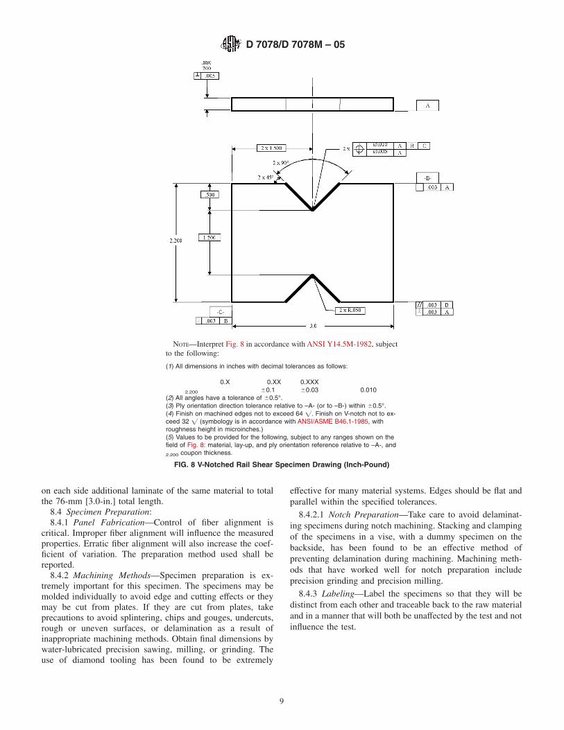
8.3 Material Orientation—Perform shear tests in any of thesix material shear planes, as defined by Fig. 1 and by properorientation of the laminate when fabricating and machining thespecimen as illustrated by Fig. 9.
NOTE 5—For example: the 1-2 plane is located in the plane formed bythe 1 and 2 axes and is oriented on the specimen so that the 1-direction(the first digit of the plane) is along the length of the specimen (X-directionin Fig. 9).
8.3.1 1-2 and 2-1 Shear Properties—The material proper-ties in the 1-2 and 2-1 planes are in-plane properties forlaminated composites. Prepare specimens for evaluation ofthese properties by cutting coupons from a [0]n, [90]n, or[0/90]ns laminate, so that the 0° direction is either along thelength of the specimen (X-direction in Fig. 9) or in the direction
D 7078/D 7078M – 05
7

of the loading axis, as appropriate. As discussed in sections 6.2and 6.5, the use of [0]n and [90]n unidirectional laminates is notrecommended.
8.3.2 1-3 and 2-3 Shear Properties—The material proper-ties in the 1-3 and 2-3 planes are interlaminar properties forlaminated composites. Prepare specimens for evaluation ofthese properties by cutting coupons from a thick (56-mm[2.20-in.]) [0]n or [90]n laminate. The thick laminate may bemanufactured several ways. The procedures in 8.3.2.1 or8.3.2.2 are equally acceptable. The procedure in 8.3.2.3 shouldbe used only if neither of the first two are possible, as thebondlines can influence the results.
8.3.2.1 Cocure the laminate to the final panel thickness in asingle operation.
8.3.2.2 Bond or co-bond in two or more operations toachieve the final panel thickness, using for the test section aprecured laminate that is greater than 31 mm [1.20 in.] thick towhich has been symmetrically bonded on each side additionallaminate to total the 56-mm [2.20-in.] total panel thickness.
8.3.2.3 Bond together in two or more operations, usinguniformly thin layers of adhesive, a minimum number ofprecured laminates to achieve the 56-mm [2.20-in.] total panelthickness.
NOTE 6—The number of bondlines traversing the notched section andthe thickness of the bondlines should be minimized to prevent theadhesive from influenceing the test results. The cumulative thickness of alladhesive bondlines traversing the notched section should be less than 5 %of the coupon width between notches.
8.3.3 3-1 and 3-2 Shear Properties—The material proper-ties in the 3-1 and 3-2 planes are interlaminar properties forlaminated composites. Prepare specimens for evaluation ofthese properties by cutting coupons from a [0]n or [90]n
laminate that is prepared as follows: Bond or co-bond in two ormore operations a number of precured layers, using for the testsection a precured laminate which is as thick as possible(preferably greater than the width of the test section; at least 6mm [0.25 in.] thick), to which has been symmetrically bonded
NOTE—Interpret Fig. 7 in accordance with ANSI Y14.5M-1982, subject to the following:
(1) All dimensions in millimetres with decimal tolerances as follows:
No decimal 0.X 0.XX63 61 60.3
(2) All angles have a tolerance of 60.5°.(3) Ply orientation direction tolerance relative to –A- (or to –B-) within 60.5°.(4) Finish on machined edges not to exceed 1.6 =. Finish on V-notch not to exceed 0.8 = (symbology is in accordance with ANSI/ASMEB46.1-1985, with roughness height in micrometers.)(5) Values to be provided for the following, subject to any ranges shown on the field of Fig. 7: material, lay-up, and ply orientation refer-ence relative to –A-, and coupon thickness.
FIG. 7 V-Notched Rail Shear Specimen Drawing (SI)
D 7078/D 7078M – 05
8
on each side additional laminate of the same material to totalthe 76-mm [3.0-in.] total length.
8.4 Specimen Preparation:8.4.1 Panel Fabrication—Control of fiber alignment is
critical. Improper fiber alignment will influence the measuredproperties. Erratic fiber alignment will also increase the coef-ficient of variation. The preparation method used shall bereported.
8.4.2 Machining Methods—Specimen preparation is ex-tremely important for this specimen. The specimens may bemolded individually to avoid edge and cutting effects or theymay be cut from plates. If they are cut from plates, takeprecautions to avoid splintering, chips and gouges, undercuts,rough or uneven surfaces, or delamination as a result ofinappropriate machining methods. Obtain final dimensions bywater-lubricated precision sawing, milling, or grinding. Theuse of diamond tooling has been found to be extremely
effective for many material systems. Edges should be flat andparallel within the specified tolerances.
8.4.2.1 Notch Preparation—Take care to avoid delaminat-ing specimens during notch machining. Stacking and clampingof the specimens in a vise, with a dummy specimen on thebackside, has been found to be an effective method ofpreventing delamination during machining. Machining meth-ods that have worked well for notch preparation includeprecision grinding and precision milling.
8.4.3 Labeling—Label the specimens so that they will bedistinct from each other and traceable back to the raw materialand in a manner that will both be unaffected by the test and notinfluence the test.
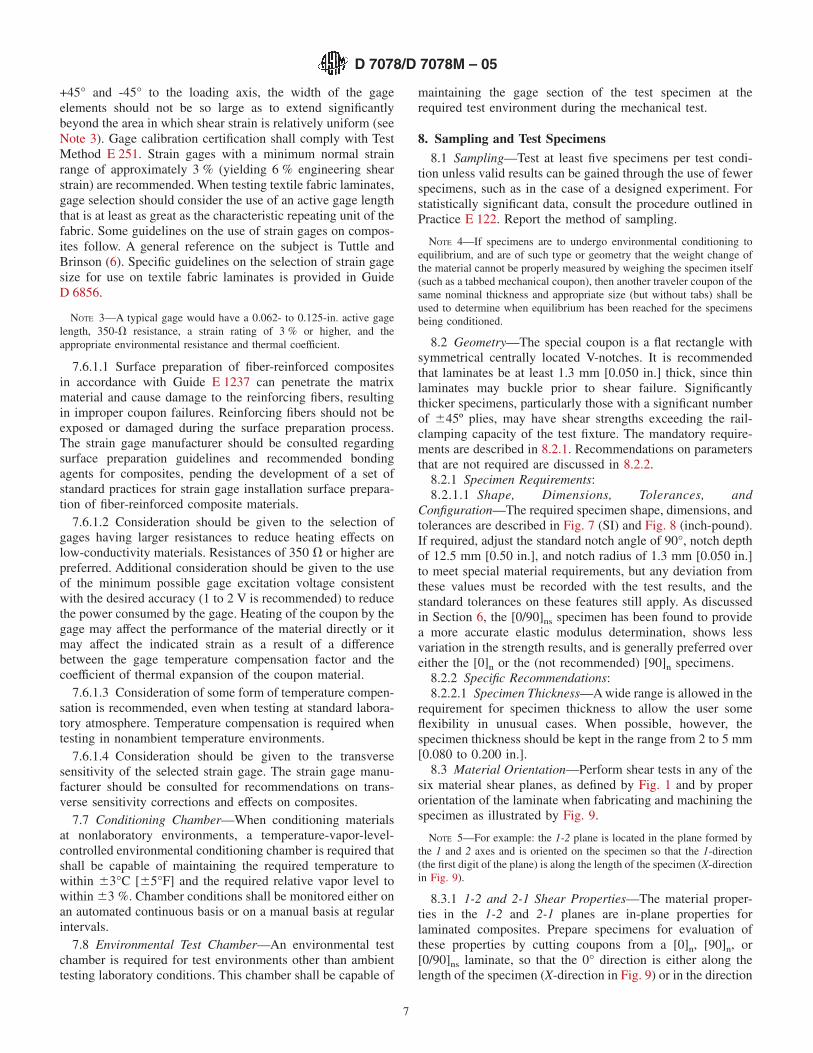
NOTE—Interpret Fig. 8 in accordance with ANSI Y14.5M-1982, subjectto the following:
(1) All dimensions in inches with decimal tolerances as follows:
0.X 0.XX 0.XXX2.200 60.1 60.03 0.010
(2) All angles have a tolerance of 60.5°.(3) Ply orientation direction tolerance relative to –A- (or to –B-) within 60.5°.(4) Finish on machined edges not to exceed 64 =. Finish on V-notch not to ex-ceed 32 = (symbology is in accordance with ANSI/ASME B46.1-1985, withroughness height in microinches.)(5) Values to be provided for the following, subject to any ranges shown on thefield of Fig. 8: material, lay-up, and ply orientation reference relative to –A-, and2.200 coupon thickness.
FIG. 8 V-Notched Rail Shear Specimen Drawing (Inch-Pound)
D 7078/D 7078M – 05
9
9. Calibration
9.1 The accuracy of all measuring equipment shall havecertified calibrations that are current at the time of use of theequipment.
10. Conditioning
10.1 Polymer Matrix Composites—Unless a different envi-ronment is specified as part of the experiment, condition thetest specimens in accordance with Procedure C of Test MethodD 5229/D 5229M and store and test at standard laboratoryatmosphere (23 6 2°C [73.4 6 3.6°F] and 50 6 10 % relativehumidity).
10.2 Nonpolymeric Materials—No conditioning environ-ment is required.
11. Procedure
11.1 Parameters to Be Specified Before Test:11.1.1 The shear specimen sampling method, coupon type
and geometry, and conditioning travelers (if required).11.1.2 The shear properties and data reporting format de-
sired.
NOTE 7—Specific material property, accuracy, and data reporting re-quirements should be determined before test for proper selection ofinstrumentation and data recording equipment. Estimates of operating
FIG. 9 Orientation of Material Planes
D 7078/D 7078M – 05
10

stress and strain levels should also be made to aid in strain gage selection,calibration of equipment, and determination of equipment settings.
11.1.3 The environmental conditioning test parameters.11.1.4 If performed, the sampling method, specimen geom-
etry, and test parameters used to determine density andreinforcement volume.
11.2 General Instructions:11.2.1 Report any deviations from this test method, whether
intentional or inadvertent.11.2.2 If specific gravity, density, reinforcement volume, or
void volume are to be reported, obtain these samples from thesame panels being shear tested. Specific gravity and densitymay be evaluated by means of Test Method D 792. Volumepercent of the constituents may be evaluated by one of thematrix digestion procedures of Test Method D 3171 or, forcertain reinforcement materials such as glass and ceramics, bythe matrix burn-off technique of Test Method D 2584. The voidcontent equations of Test Methods D 2734 are applicable toboth Test Method D 2584 and the matrix digestion procedures.
11.2.3 Following any conditioning, but before the sheartesting, measure and report the specimen width across thenotch, d1, to the nearest 25 µm [0.001 in.] and the specimenthickness at the notch, h, to the nearest 2.5 µm [0.0001 in.].Calculate the cross-sectional area as follows:
A 5 d1 3 h (1)
Record the area so obtained as the cross-sectional area forthe specimen, A, in units of mm2 [in.2]. Verify that the notchangle, depth, and radius satisfy the required tolerances.
11.2.4 Mount the strain gages such that the gage elementsare oriented at +45° and -45° to the loading axis and centeredbetween the notches.
11.3 Speed of Testing—Set the speed of testing to produce anearly constant strain rate in the gage section. If strain controlis not available on the testing machine, this may be approxi-mated by repeated monitoring and adjusting of the rate of loadapplication to maintain a nearly constant strain rate, as mea-sured by strain gage response versus time. Select the strain rateso as to produce failure within 1 to 10 min. If the ultimatestrain of the material cannot be reasonably estimated, conductinitial trials using standard speeds until the ultimate strain ofthe material and the compliance of the system are known, andthe strain rate can be adjusted. The suggested standard speedsare as follows:
11.3.1 Strain-Controlled Tests—A standard engineeringshear strain rate of 0.01 min–1.
11.3.2 Constant Head-Speed Tests—A standard head dis-placement rate of 2 mm/min [0.05 in./min].
NOTE 8—Use of a fixed head speed in testing machine systems with ahigh compliance will result in a strain rate that is much lower thanrequired.
11.4 Test Environment—Condition the specimen to the de-sired moisture profile and, if possible, test under the sameconditioning fluid exposure level. However, cases such aselevated temperature testing of a moist specimen place unre-alistic requirements on the capabilities of common testingmachine environmental chambers. In such cases, the mechani-cal test environment may need to be modified, for example, by
testing at elevated temperature with no fluid exposure control,but with a specified limit on time to failure from withdrawalfrom the conditioning chamber. Modifications to the testenvironment shall be recorded.
11.4.1 Store the specimen in the conditioned environmentuntil test time, if the testing area environment is different thanthe conditioning environment.
11.5 Specimen Insertion and Strain Gage Connection:11.5.1 Connect Gages—Connect the specimen strain gages
into the data acquisition circuitry and perform any necessarypreliminary calibrations.
NOTE 9—It is highly desirable, though not required, to be able to watchstrain-gage response during specimen installation as an aid to minimizeundesirable preloading of the specimen.
11.5.2 Zero Load—Verify load-cell calibration and zero theload display. The load shall be able to be observed duringspecimen installation to minimize undesirable preload on thespecimen.
11.5.3 Inspect the Fixture—Examine the fixture for signs ofwear in the grip area, clamping bolts, and connecting pins.Correct any deficiencies in the fixture. All bolt threads andfixture threads shall be clean and lubricated. A powderedgraphite lubricant is suggested; oils can spread onto thesurfaces of the fixture, promoting the accumulation of debrison them during subsequent testing. Inspect the gripping sur-faces to ensure that they are not damaged and are free offoreign matter. Examine the gripping surfaces for residue fromprevious test specimens. If necessary, clean the grippingsurfaces. A brass wire brush is suggested for removing residuefrom the gripping surfaces.
11.5.4 Loosen Gripping Bolts—Loosen the gripping bolts ofeach fixture half sufficiently to allow the specimen thickness tobe freely inserted into the cavity between the gripping plateswith clearance.
11.5.5 Insert Specimen into First Fixture Half—Place thespecimen loosely into one fixture half with the spacer block(optional) in place and adjust the strain gage lead wires. Theend blocks of the spacer should be tightened so that the spacerattaches securely to the fixture half. Adjust the three clampingbolts in one side of the fixture half such that the specimen isaligned with centering scribe marks on the spacer. Hand-tighten the three clamping bolts on the other side of the fixturehalf to lightly grip the specimen. Ensure that the notches on thespecimen are aligned with the spacer blocks, as shown in Fig.10. Tighten each clamping bolt to a value 1⁄2 of the maximumclamping torque. Finally tighten each bolt to the requiredclamping torque. A bolt torque of 55 N-m [40 ft-lb] isrecommended.
NOTE 10—The required bolt torque may vary depending on the type ofmaterial and the thickness of the specimen being tested. A torque of 45 to55 N-m [35 to 40 ft-lb] has been found to be sufficient for most materialsof typical specimen thicknesses. If the torque is too low for a givenconfiguration, the specimen may slip relative to the gripping surfaces. Ifthe torque is excessive, the high clamping force will induce detrimentalstress concentrations in the specimen at the sides of the gage section andmay lead to premature failures. Thus, a minimal value of bolt torquesufficient to prevent specimen slippage should be used. This may requireseveral trials when testing an unfamiliar material. However, it has beenshown that the acceptable range of bolt torques is very broad (1).
D 7078/D 7078M – 05
11

11.5.6 Zero Strain Gages—Zero the strain gage outputswith the specimen inserted into one fixture half.
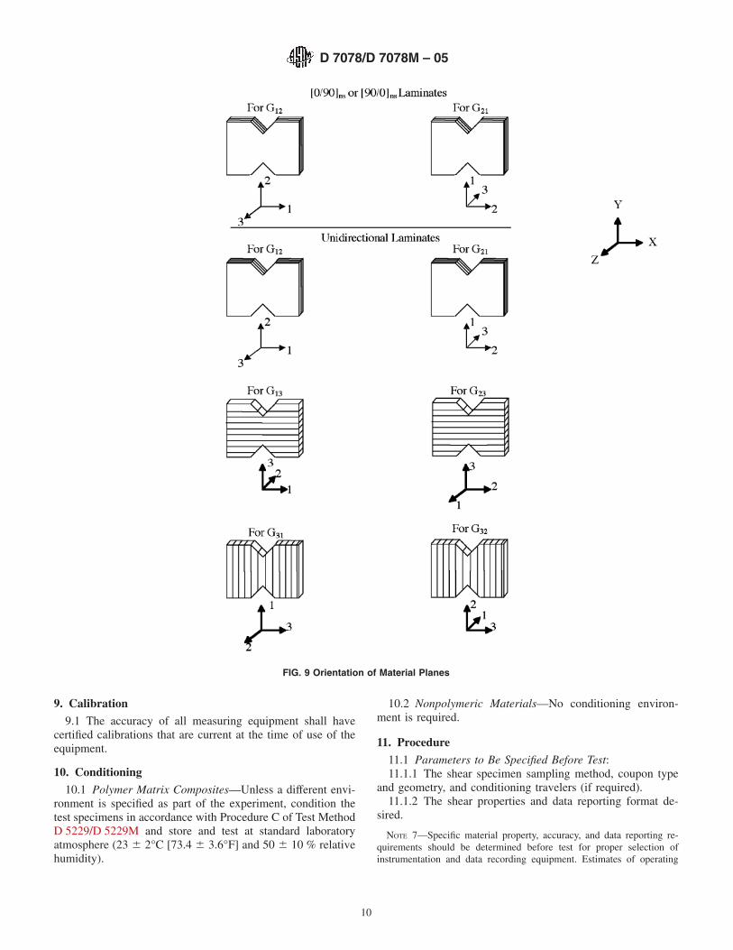
11.5.7 Insert Specimen into Second Fixture Half—Place thesecond fixture half onto the specimen. The two spacer blocks(optional) used for orienting the specimen in the first fixturehalf are used to orient the second fixture half and obtain theproper spacing between fixture halves. It may be necessary toloosen the spacer end blocks to attach the second fixture half.The spacer end blocks should be retightened to secure thespacers to the fixture. The clamping bolts are tightened in thesame manner of the first rail. This assembly is shown in Fig.11.
11.6 Fixture Installation—Attach the test fixture halves tothe upper and lower test machine heads. The adapters that areshown in the test fixture drawings are optional and are testmachine dependent.
NOTE 11—This test is run in tension in a testing machine with astationary head and a moving head. While a vertical testing machine is nota requirement of this test method, for ease of description the instructionsthat follow assume the use of a vertical testing machine. The location ofthe moving head relative to the stationary head, as long as they createtension, or to which head the load transducer is attached are not important.
11.7 Remove Spacer—Remove the screws holding thespacer end blocks. Each spacer should now freely slide out ofthe assembled fixture.
11.8 Loading—Apply the load to the specimen at thespecified rate until failure, while recording data.
11.9 Data Recording—Record load versus strain and loadversus head displacement continuously, or at frequent regularintervals. If a load-strain or load-displacement discontinuityoccurs or initial ply failures are observed, record the load,strain, and mode of damage at such points. If the specimen isto be failed, record the maximum load before failure and thestrain at, or as near as possible to, the moment of rupture. Ifultimate failure does not occur within 5 % strain, the data shallbe truncated to this value. Guidance on interpretation of failureload is given in Section 6.
11.10 Failure Mode—Record the mode and location offailure of the specimen.
12. Calculation
12.1 Shear Stress/Ultimate Strength—Calculate the ultimatestrength using Eq 2 and report the results to three significantfigures. If the shear modulus is to be calculated, determine theshear stress at each required data point using Eq 3.
Fu5 Pu/A (2)
ti 5 Pi/A (3)
where:Fu = ultimate strength, MPa [psi];Pu = the lower of ultimate or load at 5 % engineering shear
strain, N [lbf];ti = shear stress at ith data point, MPa [psi];Pi = load at ith data point, N [lbf]; andA = cross-sectional area from 11.2.3, mm2 [in.2].
12.2 Shear Strain/Ultimate Strain—If shear modulus orultimate strain is to be calculated, determine the engineeringshear strain from the indicated normal strains at +45° and -45°at each required data point using Eq 4. The ultimate engineer-ing shear strain is determined from Eq 5. Report the results tothree significant figures.
gi 5 | e 145 | 1 | e–45 | (4)
gu
5 min of 5 % or g at ultimate load (5)
where:gi = engineering shear strain at ith data point, µe;e +45 = + 45° normal strain at ith data point, µe;e-45 = –45° normal strain at ith data point, µe; andgu = ultimate engineering shear strain, µe.
12.3 Shear Modulus of Elasticity:
NOTE 12—To minimize potential effects of twisting, it is recommendedthat the strain data used for modulus of elasticity determination be theaverage of the indicated strains from each side of the specimen, asdiscussed in Section 6.
12.3.1 Shear Chord Modulus of Elasticity—Calculate theshear chord modulus of elasticity using Eq 6, applied over a
FIG. 10 Use of Spacers for Specimen Alignment
D 7078/D 7078M – 05
12
4000 6 200-µe engineering shear strain range, starting with thelower strain point in the range of 1500 to 2500 µe inclusive. Ifdata are not available at the exact strain range end points (asoften occurs with digital data), use the closest available datapoint. Report the shear chord modulus of elasticity to threesignificant figures. Also report the strain range used in thecalculation. A graphical example of shear chord modulus isshown in Fig. 2.
Gchord5 Dt/Dg (6)
where:Gchord = shear chord modulus of elasticity, GPa [psi];Dt = difference in applied shear stress between the two
strain points; andDg = difference between the two engineering shear
strain points (nominally 4000 µe).12.3.2 Shear Modulus of Elasticity (Other Definitions)—
Other definitions of elastic modulus may be evaluated andreported at the user’s discretion. If such data is generated andreported, report also the definition used, the strain range used,and the results to three significant figures. Test Method E 111provides additional guidance in the determination of modulusof elasticity.
NOTE 13—An example of another modulus definition is the secondarychord modulus of elasticity for materials that exhibit essentially bilinearstress-strain behavior.
12.4 Offset Shear Strength—Determine the offset shearstrength by translating the shear chord modulus of elasticityline along the strain axis from the origin by a fixed strain valueand extend this line until it intersects the stress-strain curve.Determine the shear stress that corresponds to the intersectionpoint and report this value, to three significant digits, as theoffset shear strength, along with the value of the offset strain,as in:
F° ~0.2 % offset! 5 28 MPa (7)
12.5 Statistics—For each series of tests calculate the aver-age value, standard deviation, and coefficient of variation (inpercent) for each property determined:
x̄ 5
(i 5 1
n
xi
n (8)
sn21 5Œ(i 5 1
n
xi2
2 nx̄2
n 2 1 (9)
CV 5 100 3sn21
x̄ (10)
where:x̄ = sample mean (average);sn-1 = sample standard deviation;CV = sample coefficient of variation, %;n = number of specimens; andxi = measured or derived property.
13. Report
13.1 The data reported with this test method include me-chanical testing data and material identification data and shallbe in accordance with Guides E 1434 and E 1309, respectively.Report the following information, or references pointing toother documentation containing this information, to the maxi-mum extent applicable. (Reporting of items beyond the controlof a given testing laboratory, such as might occur with materialdetails of panel fabrication parameters, shall be the responsi-bility of the requestor):
13.1.1 The revision level or date of issue of this test method.13.1.2 The date(s) and location(s) of the test.13.1.3 The name(s) of the test operator(s).13.1.4 Any variations to this test method, anomalies noticed
during testing, or equipment problems occurring during testing.13.1.5 Identification of the material tested including: mate-
rial specification, material type, material designation, manufac-turer, manufacturer’s lot or batch number, source (if not frommanufacturer), date of certification, expiration of certification,filament diameter, sizing, tow or yarn filament counts andtwist, yarn spacings, fabric type, fiber areal weight, matrixtype, prepreg matrix content, and prepreg volatiles content.
FIG. 11 Use of Spacers For Final Fixture Alignment
D 7078/D 7078M – 05
13
13.1.6 Description of the fabrication steps used to preparethe laminate including: fabrication start date, fabrication enddate, process specification, cure cycle, consolidation method,and a description of the equipment used.
13.1.7 Ply orientation stacking sequence of the laminate.13.1.8 If requested, report density, volume percent rein-
forcement, and void content test methods, specimen samplingmethod and geometries, test parameters, and test results.
13.1.9 Average ply thickness of the material.13.1.10 Results of any nondestructive evaluation tests.13.1.11 Method of preparing the test specimens, including
specimen labeling scheme and method, specimen geometry,sampling method, specimen cutting method, identification oftab geometry, tab material, and tab adhesive used.
13.1.12 Calibration dates and methods for all measurementand test equipment.
13.1.13 Type of test machine, alignment results, and dataacquisition sampling rate and equipment type.
13.1.14 Dimensions of each test specimen.13.1.15 Conditioning parameters and results, use of travel-
ers and traveler geometry, and the procedure used if other thanthat specified in the test method.
13.1.16 Relative humidity and temperature of the testinglaboratory.
13.1.17 Environment of the test machine environmentalchamber (if used) and soak time at environment.
13.1.18 Number of specimens tested.13.1.19 Speed of testing.13.1.20 The strain-gage type, resistance, size, gage factor,
temperature compensation method, transverse sensitivity, lead-wire resistance, and any correction factors used.
13.1.21 Load-displacement and stress-strain curves for eachspecimen.
13.1.22 Tabulated data of stress versus strain for eachspecimen.
13.1.23 Percent twisting results for each specimen so evalu-ated.
13.1.24 Individual strengths and average value, standarddeviation, and coefficient of variation (in percent) for thepopulation. Note if the failure load was less than the maximumload prior to failure.
13.1.25 Individual ultimate engineering shear strains andthe average value, standard deviation, and coefficient of varia-tion (in percent) for the population. Note any test that wastruncated to 5 % strain.
13.1.26 Strain range used for chord shear modulus determi-nation.
13.1.27 If another definition of modulus of elasticity is usedin addition to chord modulus, describe the method used, theresulting correlation coefficient (if applicable), and the strainrange used for the evaluation.
13.1.28 Individual values of shear chord modulus of elas-ticity, and the average value, standard deviation, and coefficientof variation (in percent) for the population.
13.1.29 Individual values of offset shear strength with thevalue of the offset strain, along with the average, standarddeviation, and coefficient of variation (in percent) values forthe population.
13.1.30 Failure mode and location of failure for eachspecimen.
14. Precision and Bias14.1 Precision—The data required for the development of a
precision statement is not available for this test method.14.2 Bias—Bias cannot be determined for this test method
as no acceptable reference standard exists.
15. Keywords15.1 composite materials; in-plane shear; interlaminar
shear; shear modulus; shear properties; shear strength; sheartesting
REFERENCES
(1) Adams, D. O., Moriarty, J. M., Gallegos, A. M., and Adams, D. F.,“Development and Evaluation of the V-Notched Rail Shear Test forComposite Laminates,” Federal Aviation Administration Report DOT/FAA/AR-03/63, FAA Office of Aviation Research, Washington, D.C.,September, 2003.
(2) Adams, D. O., Moriarty, J. M., Gallegos, A. M., and Adams, D. F.,“Development and Evaluation of a V-Notched Rail Shear Test,”proceedings of the 2002 SAMPE Technical Conference, Baltimore,MD, November 5-8, 2002.
(3) Adams, D. O., Gallegos, A. M., Moriarty, J. M., and Adams, D. F., “AV-Notched Rail Shear Test for Composite Laminates,” proceedings ofthe 2002 SEM Annual Conference, Milwaukee, WI, June 10-12, 2002.
(4) Hussain, A. K. and Adams, D. F., “The Wyoming-Modified Two-RailShear Test Fixture for Composite Materials,” Journal of CompositesTechnology and Research, JCTRER, Vol 21, October 1999, pp.215-223.
(5) Hussain, A. K. and Adams, D. F., “An Analytical and ExperimentalEvaluation of the Two-Rail Shear Test for Composite Materials,”University of Wyoming Composite Materials Research Group ReportUW-CMRG-R-98-105, February 1998.
(6) Tuttle, M. E., and Brinson, H. F., “Resistance-Foil Strain-GageTechnology as Applied to Composite Materials,” Experimental Me-chanics, Vol 24, No. 1, March 1984, pp. 54–65; errata noted in Vol 26,No. 2, June 1986, pp. 153–154.
D 7078/D 7078M – 05
14

ASTM International takes no position respecting the validity of any patent rights asserted in connection with any item mentionedin this standard. Users of this standard are expressly advised that determination of the validity of any such patent rights, and the riskof infringement of such rights, are entirely their own responsibility.
This standard is subject to revision at any time by the responsible technical committee and must be reviewed every five years andif not revised, either reapproved or withdrawn. Your comments are invited either for revision of this standard or for additional standardsand should be addressed to ASTM International Headquarters. Your comments will receive careful consideration at a meeting of theresponsible technical committee, which you may attend. If you feel that your comments have not received a fair hearing you shouldmake your views known to the ASTM Committee on Standards, at the address shown below.
This standard is copyrighted by ASTM International, 100 Barr Harbor Drive, PO Box C700, West Conshohocken, PA 19428-2959,United States. Individual reprints (single or multiple copies) of this standard may be obtained by contacting ASTM at the aboveaddress or at 610-832-9585 (phone), 610-832-9555 (fax), or [email protected] (e-mail); or through the ASTM website(www.astm.org).
D 7078/D 7078M – 05
15