standard owner’s manual - microcutsystems.com€¦ · standard owner’s manual c&p...
TRANSCRIPT
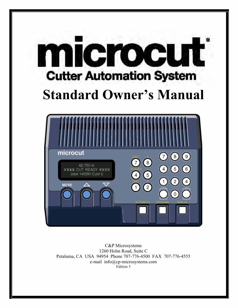
Standard Owner’s Manual
C&P Microsystems 1260 Holm Road, Suite C
Petaluma, CA USA 94954 Phone 707-776-4500 FAX 707-776-4555 e-mail [email protected]
Edition 3

Thank you for purchasing a microcut control system for your paper cutter. Having done so, you have joined over 15,000 microcut users worldwide who are enjoying the benefits of computer-controlled cutting. microcut is a state of the art system for controlling backgauge movement, with an intuitive, easy to use operator interface. microcut features room for over 4,000 cuts, divided into as many jobs. There are four basic operating methods—
• Turning the power on and getting started. • Manual operation. • Programming and reviewing jobs. • Automatic operation.
Many of the features you will find in microcut have resulted from operator's ideas throughout the world. If you have any suggestions, we encourage your input. Where possible, we will make the revisions and update your unit. Our special thanks to all who have helped make microcut the world leader in cutter automation.
microcut can be installed on any type of guillotine paper cutter that uses a leadscrew for backgauge movement. Other methods of backgauge movement, such as chain or cable drive, cannot assure the accuracy or positioning speed. In these cases it is suggested that either a leadscrew kit be installed or that the machine be replaced.
microcut is not intended to control the knife or the clamp on the paper cutter. Anything dealing with the clamp or knife is not to be tampered with or adjusted during the installation or operation of microcut. Any alteration to the knife or clamp safeties, circuits, or operation, or any installation technique that compromises the safety of anyone working on or around the machine is STRICTLY FORBIDDEN. Guarding may need to be altered or added to offer proper protection when microcut parts and assemblies are added to the machine. Never operate the machine until all guarding is complete. All moving parts and hazards must be covered in such a way as to prevent accidental contact of any sort. Any nip, draw-in, crush, or shearing hazard must be evaluated and eliminated.
microcut® is a registered trademark of C&P Microsystems LLC
THIS DOCUMENT CONTAINS PROPRIETARY INFORMATION THAT IS PROTECTED BY COPYRIGHT. ALL RIGHTS ARE RESERVED. NO PART OF THIS DOCUMENT MAY BE PHOTOCOPIED, REPRODUCED, OR TRANSLATED TO ANOTHER LANGUAGE WITHOUT THE PRIOR WRITTEN CONSENT OF GMS. ALL SPECIFICATIONS ARE SUBJECT TO CHANGE
WITHOUT NOTIFICATION. C&P MICROSYSTEMS ASSUMES NO LIABILITY FOR OMISSIONS IN THIS DOCUMENT OR FROM THE USE OR MISUSE RESULTING FROM INFORMATION CONTAINED WITHIN.
Introduction


1
The microcut installation is basically mechanical. It involves mounting the display console; the H-drive box; the DC motor to drive the backgauge; the shaft encoder to signal backgauge movement to the computer; and four sensing switches to inform the computer of the machine status (clamp, knife, clamp shoe, and position). All low voltage cables are plug-in type. Wiring is required for the power and motor.
The following text gives a conceptual approach toward the installation. Use this manual to learn what each component must do. Mount each component in the fashion best suited to fulfill its purpose.
microcut is a retrofit system so every installation is unique. Install the components for function as well as fit. The brackets are designed with extra holes and slots. They are easily modified, and can be adapted for almost any requirement. Installation variables include the encoder sprockets, pulley (Schneider cutters have a flat belt drive), and motor size. If the leadscrew diameter is known at the time of shipment, the leadscrew sprocket will be bored to the proper dimension. Otherwise, it may be necessary to have the sprocket bored to size. Check the sprocket before beginning the installation. If it must be bored, take care of this NOW to avoid unnecessary delays later. Cut the sprocket in half to allow easier installation.
Every display console is identical regardless of machine type. A setup routine is resident in the computer to allow simple adaptation to any machine. This routine must be completed on every installation in order for microcut to know the machine it is installed on and to operate safely and correctly.
Hints— 1. Inspect the machine to insure all operations are correct. Fix problems now, not later. 2. The boxes are packed to facilitate the installation. The installation will be easier if the parts are
not mixed up. • Box 1 contains the backgauge drive motor. • Box 2 contains the motor drive, encoder, sensors, and various brackets. • Box 3 contains the encoder sprockets, manual, display, and mounting bracket.
3. Use the thinnest drive belt possible to minimize belt flex around the pulley. 4. Do not over-tighten the backgauge. If there are nylon gliders supporting the backgauge keep
them loose to minimize leadscrew flex. 5. Use only one belt per pulley. Multiple belts on any pulley will cause slower settling. 6. The H-drive servo control unit works best when the belt is fairly tight. This is in contrast with the
older SCR drives that preferred a very loose belt. 7. Wire the display to the H-Drive, the H-Drive to line power, and hold the MANUAL key at power
on to access demonstration mode. Let the operator learn the system while the installation is occurring.
Installation Basics
2
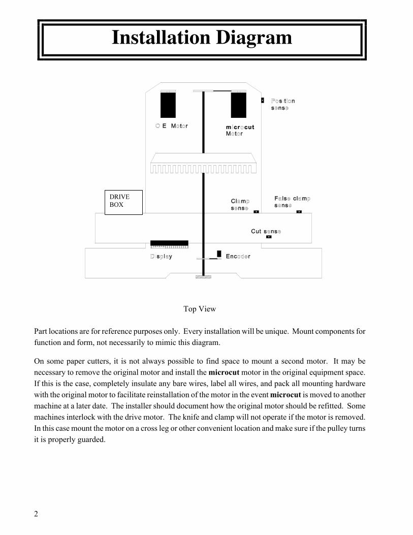
Top View Part locations are for reference purposes only. Every installation will be unique. Mount components for function and form, not necessarily to mimic this diagram.
On some paper cutters, it is not always possible to find space to mount a second motor. It may be necessary to remove the original motor and install the microcut motor in the original equipment space. If this is the case, completely insulate any bare wires, label all wires, and pack all mounting hardware with the original motor to facilitate reinstallation of the motor in the event microcut is moved to another machine at a later date. The installer should document how the original motor should be refitted. Some machines interlock with the drive motor. The knife and clamp will not operate if the motor is removed. In this case mount the motor on a cross leg or other convenient location and make sure if the pulley turns it is properly guarded.
Installation Diagram

3
You may want to adapt this list. The procedures are listed in their order of execution, as well as the tools required to proceed. An installation will be faster if all tasks in a given section are completed before starting the next.
DETERMINE ALL DRILLING LOCATIONS—Mark all holes that will be drilled to complete mounting of ALL components, including holes to secure ty strap brackets, at the same time.
• Slide T square with level • Pencil
DRILL ALL HOLES—Protect the machine from drill shavings, then drill all holes necessary to mount all components. Use the pilot drill for all holes before increasing drill size to save time. Be careful not to drill any hole too large as the drill size is increased.
• Paper and rags to cover machine surfaces • Pilot, #7, 5/16" high speed drill bits • Electric hand drill • Extension cord
TAP ALL HOLES—Complete all threads for all of the components. • 1/4-20, 3/8-16 taps • Tap handle (ratchet type is convenient) • Tapping fluid
CLEAN THE MACHINE—Clean the machine to prevent future damage. • Brush • Rags • Magnet
BOLT AND SECURE ALL PARTS TO THE MACHINE-- • 7/16, 9/16 wrenches and sockets • Phillips screw driver • Hacksaw to saw off excess threaded rod
ROUTE THE CABLES—Complete wiring of all components. Use ty straps to secure the wiring. • Side cut pliers • Wire strippers • Screwdrivers
Guide and Tool List
4
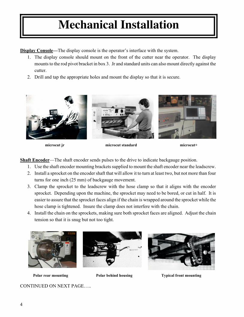
Display Console—The display console is the operator’s interface with the system. 1. The display console should mount on the front of the cutter near the operator. The display
mounts to the rod pivot bracket in box 3. Jr and standard units can also mount directly against the cutter.
2. Drill and tap the appropriate holes and mount the display so that it is secure. microcut jr microcut standard microcut+
Shaft Encoder—The shaft encoder sends pulses to the drive to indicate backgauge position. 1. Use the shaft encoder mounting brackets supplied to mount the shaft encoder near the leadscrew. 2. Install a sprocket on the encoder shaft that will allow it to turn at least two, but not more than four
turns for one inch (25 mm) of backgauge movement. 3. Clamp the sprocket to the leadscrew with the hose clamp so that it aligns with the encoder
sprocket. Depending upon the machine, the sprocket may need to be bored, or cut in half. It is easier to assure that the sprocket faces align if the chain is wrapped around the sprocket while the hose clamp is tightened. Insure the clamp does not interfere with the chain.
4. Install the chain on the sprockets, making sure both sprocket faces are aligned. Adjust the chain tension so that it is snug but not too tight.
Polar rear mounting Polar behind housing Typical front mounting
CONTINUED ON NEXT PAGE…..
Mechanical Installation
5
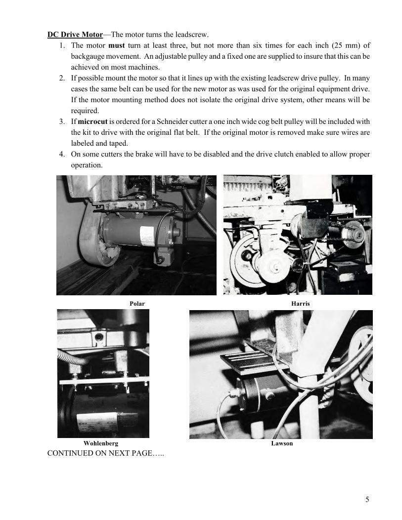
DC Drive Motor—The motor turns the leadscrew.
1. The motor must turn at least three, but not more than six times for each inch (25 mm) of backgauge movement. An adjustable pulley and a fixed one are supplied to insure that this can be achieved on most machines.
2. If possible mount the motor so that it lines up with the existing leadscrew drive pulley. In many cases the same belt can be used for the new motor as was used for the original equipment drive. If the motor mounting method does not isolate the original drive system, other means will be required.
3. If microcut is ordered for a Schneider cutter a one inch wide cog belt pulley will be included with the kit to drive with the original flat belt. If the original motor is removed make sure wires are labeled and taped.
4. On some cutters the brake will have to be disabled and the drive clutch enabled to allow proper operation.
Polar Harris Wohlenberg Lawson CONTINUED ON NEXT PAGE…..
6
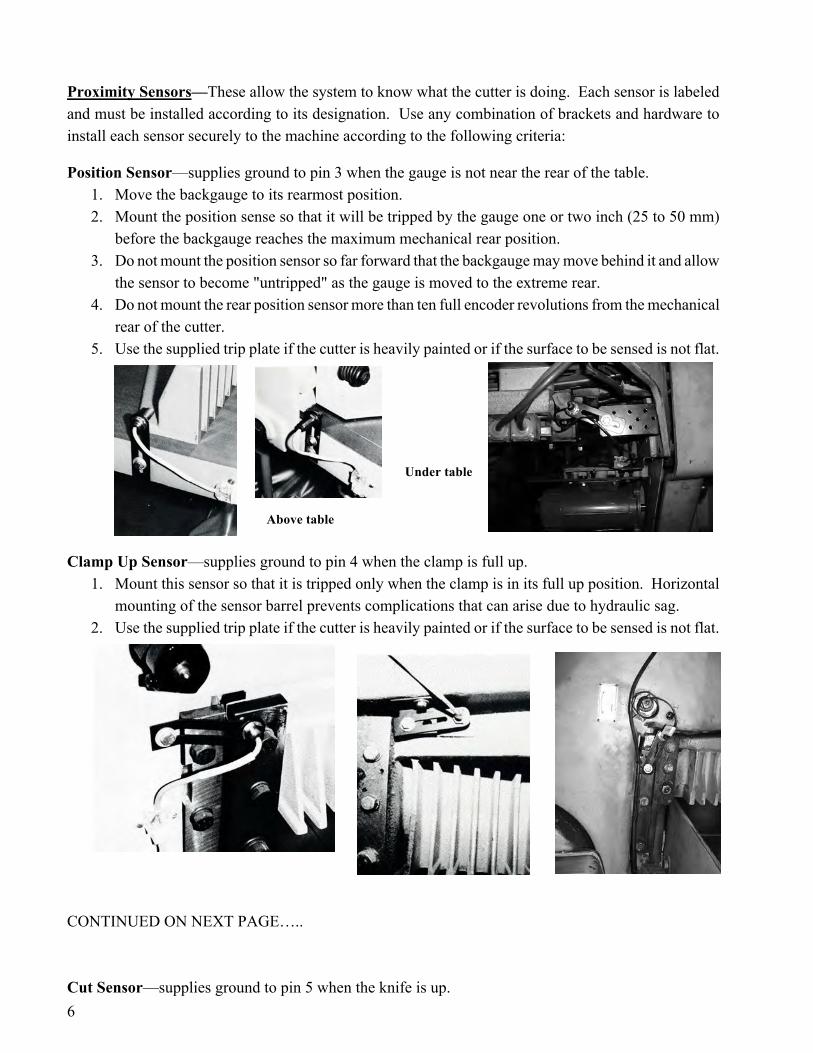
Proximity Sensors—These allow the system to know what the cutter is doing. Each sensor is labeled and must be installed according to its designation. Use any combination of brackets and hardware to install each sensor securely to the machine according to the following criteria:
Position Sensor—supplies ground to pin 3 when the gauge is not near the rear of the table. 1. Move the backgauge to its rearmost position. 2. Mount the position sense so that it will be tripped by the gauge one or two inch (25 to 50 mm)
before the backgauge reaches the maximum mechanical rear position. 3. Do not mount the position sensor so far forward that the backgauge may move behind it and allow
the sensor to become "untripped" as the gauge is moved to the extreme rear. 4. Do not mount the rear position sensor more than ten full encoder revolutions from the mechanical
rear of the cutter. 5. Use the supplied trip plate if the cutter is heavily painted or if the surface to be sensed is not flat.
Under table Above table Clamp Up Sensor—supplies ground to pin 4 when the clamp is full up.
1. Mount this sensor so that it is tripped only when the clamp is in its full up position. Horizontal mounting of the sensor barrel prevents complications that can arise due to hydraulic sag.
2. Use the supplied trip plate if the cutter is heavily painted or if the surface to be sensed is not flat.
CONTINUED ON NEXT PAGE….. Cut Sensor—supplies ground to pin 5 when the knife is up.

7
1. Mount this sensor to the side of the opening in front of the knife bar so that it is tripped near the bottom of the knife stroke.
2. This sensor must be tripped for at least 1/4 second during the knife cycle to register a cut. 3. This sensor must only be tripped once per knife stroke. Beware the double-tripping effect that
holes, lips, and bolt heads can cause.
Clamp Shoe Sensor—supplies ground to pin 6 when the clamp shoe is in the holder.
1. Mount this sensor so that it is tripped when the clamp shoe (false clamp or sole plate) is resting in its holder. If there is no clamp shoe holder, use the multi-angled brackets supplied to create one.
NOTE: The electrical purpose of each sensor is supplied in case the sensor is replaced with a different type of a switch. When the sensor is not supplying
ground it presents an open circuit. With the cable pointing up and the tab facing you, pin 1 is to the left. The wiring at pin 1 is 12VDC and pin 2 is ground. Pins 3 to 6 are the signal lines from each sensor as defined in the installation instructions.
Drive Box—The drive box drives the gauge motor and acts as a junction box for the wiring. 1. Install this in a central location to all of the other parts. Make sure the cables will reach all of the
components. Avoid mounting this box on a moving panel. Keep this box in the open to allow maximum cooling. Ideally the fins will be vertical to insure optimal cooling.

8
Be sure that the original equipment backgauge motor cannot drive the leadscrew. Be certain that the original equipment backgauge brake will not energize during motor drive. If a clutch needs to be locked on (electrically or mechanically) to allow the microcut motor to drive, do this now. If any modifications are made completely insulate any bare wires, label all wires, and pack all original parts that were removed. To facilitate reinstallation of the original drive system in the event microcut is moved to another machine at a later date, the installer should document how the original motor should be refitted. Check the machine for operation in case any of the above modifications may have affected operation.
Use the ty straps and ty strap mounting bases to secure all cables appropriately.
Four 6 pin cables are supplied in various lengths for the proximity sensors. In-line connectors are supplied for larger machines that may require longer runs using multiple cables. Plug a cable into a sensor. Route the cable along the desired route and plug it into the drive box. The four sensors may be plugged into the four receptacles in any order. Repeat the procedure for each sensor.
Two 8 pin cables are supplied in different lengths. Select the desired length cable. An in-line connector is supplied for larger machines that may require a longer run using both cables. Plug the cable into the encoder. Route the cable along the desired route and plug it into the drive box.
Plug the round cable into the display console. Route the cable along the desired route and plug it into the drive box.
Connect the motor cable (male terminal plug) to the motor using the connectors supplied. The earth (frame) wire should only be connected if the motor is not electrically attached to the machine. Route the cable along the desired route and plug it into the drive box.
microcut is equipped with an air table control line (relay not supplied). Refer to the schematic pages at the back of this manual for details.
Connect the power cable (female terminal plug) to any 85 to 250 VAC source. The center of the plug (yellow wire with green tracer) is the earth connection. The other two lines are for the power. Check the plug to make sure this is correct. Plug the cable into the drive box.
Wiring and Power

9
Insure that— • The machine is fully cleaned from the installation. • All parts are securely mounted to the machine. • The motor pulley is secure. • The motor drive belt is correctly aligned. • The encoder chain is aligned. • The encoder sprocket clamp does not interfere with the chain or machine. • All cables are secure and clear of all machine operations. • All machine operations are functioning properly.
Review the machine for any areas that could create hazards such as pinch points or exposed parts. Guard as appropriate. Remember microcut is not intended to control the knife or the clamp on the paper cutter. Anything dealing with the clamp or knife is not to be tampered with or adjusted during the installation or operation of microcut. Any alteration to the knife or clamp safeties, circuits, or operation, or any installation technique that compromises the safety of anyone working on or around the machine is STRICTLY FORBIDDEN. Guarding may need to be altered or added to offer proper protection when microcut parts and assemblies are added to the machine. Never operate the machine until all guarding is complete. All moving parts and hazards must be covered in such a way as to prevent accidental contact of any sort. Any nip, draw-in, crush, or shearing hazard must be evaluated and eliminated.
Show the operator the installation, making sure he is comfortable with all mounting locations. The set up routine (next page) must be completed to allow correct operation. It is a good idea to go through this routine with the operator so that he is familiar with the approach and can select the correct machine sizes and operating parameters.
Final Check
10
All microcut units must be told what type of machine they have been installed on before they can operate properly. A resident setup routine exists to allow this to be done easily. At initial power on follow through to the Press Automatic to Start screen and press OPTIONS. An entry screen will appear and you will—
1. Be asked which languages you wish to install. 2. Wait for the memory test to complete. 3. Select the units of measurement. 4. Verify the motor turns ratio by having someone turn the hand wheel so that the gauge moves the
specified distance while you count the turns the motor pulley makes. Make adjustments if necessary.
5. Wait for the data down load to the drive panel. 6. Test the motor direction (if incorrect, then remove the power and switch the wires at the motor). 7. Let the system calibrate to the rear and then move the gauge and enter a precise rear reference
position. 8. Bring the back gauge to the front and enter a precise front reference position. 9. Key in the table sizes for max rear, clamp shoe, and minimum front. 10. Select the desired backgauge speed. 11. Enter the tolerance*. 12. Select the desired units of measurement to be enabled or disabled. 13. Enable or disable the auto push out feature (forced push out in auto mode after a cut if the next
target requires reverse drive). The unit will restart automatically. NOTE: for OEM applications where the leadscrew pitch is already known the reference position steps will be skipped. At the end of the setup routine the gauge will move back to calibrate and ask you to enter a calibration value at that time. * The tolerance allows the display to settle on a position. Almost all mechanical systems contain a certain amount of flex or vibration. If the tolerance is too small, any flex or vibration will cause the current position display to flutter between numbers. Generally the tolerance is set to .003 inches (.007 cm), although tighter tolerances can be selected. To insure the display is stable, the drive control will re-correct the gauge anytime that the error is more than half of the tolerance setting. A .003 setting will yield actual accuracy to .0015 inches (.004 cm). Larger tolerances allow faster positioning and faster cutting.
Setup Routine

11
If this is a new installation, go through the SETUP routine before continuing (see the previous page).
Supply power to the system. The software versions will appear on the screen and certain tests will be
performed. The display will ask what language you would like to use (if more than one language was
installed in the set up routine) and then ask you to verify the guards, daily lubrication, and that everyone
is clear of the machine. Answer YES when each has been verified. You will then be asked to press
AUTOMATIC to start. At that time the system will--
1. Check the circuits and if everything is OK continue automatically. If there are any errors
microcut will display the problems with an error message so that they can be corrected. If there
are errors in the memory the SETUP routine will be forced. Refer to the previous page of this
manual.
2. The backgauge direction will be tested and then be driven slowly to the rear of the cutter to
calibrate. NOTE: If microcut is already at the rear of the table it will move the backgauge
forward before going back.
microcut is now ready to use.
microcut has been designed with four basic key groups for operator control. These groups are--
NUMBERS—used for entering position information and for moving the backgauge.
MODE—used for selecting manual, program, review, or automatic operation.
LAST , UNITS , OPTIONS—used back up a step, change units of measurement, or select options.
DRIVE—used for moving the backgauge.
Getting Started

12
In normal operation the top line of the screen shows the current backgauge position. The second line will show the operating mode or selected feature. The left side of the third line will show the selected job (dashes if no job is selected) with the cut number on the right side. The bottom line will show the keyed in position value. Any time a buzzer pulses, the display will show a message that you should read. Press ANY KEY to continue. Some screens will offer options which you can select by pressing the NO key or ARROWS to point to a line and YES to accept it, or the 1, 2, or 3 keys to choose the line directly.
The Screen
Operator’s console
Current position
Status or operating mode
Job number Cut number
Keyed in value
Backgauge DRIVE keys
Operating mode keys—MANUAL, PROGRAM
(and review), and AUTOMATIC
NUMBER keypad

13
OPERATING MODES: Four basic operating modes are available: MANUAL for basic drive operations, PROGRAM to create
new jobs, REVIEW to look up old jobs, and AUTOMATIC to sequence position to position as described
by a selected job.
BACKGAUGE MOVEMENT:
Press FORWARD or REVERSE to move the backgauge slowly at first, faster with time. To move to a specific
position, use NUMBERS and + , - , / to display the target value and press MOVE. In the case of the FORWARD or
REVERSE keys, auto correction will remain off allowing the hand wheel to be used for fine adjustment.
Auto correction will engage after any move to a specific location (automatic operation or with the MOVE
key).
The UNITS key can be pressed at any time to change from inches to centimeters to millimeters and back to inches. For a unit to be selected it must be enabled. Refer to the MANUAL MODE options for enabling or disabling the units.
The LAST key can be pressed in program, review, or automatic operation to back up a step. AIR CONTROL:
Press + and then YES to enable the air. Press - and then YES to disable the air. If this is done in PROGRAM, REVIEW, or AUTOMATIC modes the air status will be saved with the cut. The air table will then switch on and off automatically when using the job. It is also possible to program the air status for after the cut while the clamp is still in the down position. To do this in automatic mode, hold the clamp down with the foot treadle, cycle the knife, and then press + or - followed by the YES key. The air after cut status defaults to the off position during programming to prevent small labels from being displaced after the cut. If a larger sheet is in front of the knife after the cut, and the air table is needed to move it, then turn the air after cut on. NOTE: In auto mode the air will be forced on for any reverse or push out drive request. Note: Actual control of the air table requires optional hardware.
Features

14
MANUAL is the basic operating mode. The backgauge can be moved by pressing the FORWARD or REVERSE or use NUMBERS and + , - , / to display the target value and press MOVE. In the case of the FORWARD or REVERSE keys, auto correction will remain off allowing the hand wheel to be used for fine adjustment. Auto correction will engage after any move to a specific location with the MOVE key.
Press OPTIONS to access the features that can be adjusted from the manual mode. Use the ARROW, NUMBER,
YES , or NO keys to make selections. You can exit at any time by pressing the MANUAL key. The system
will return to manual mode automatically when the last feature is completed. The screens in order are—
1. Select your language (if more than one language is installed).
2. Calibrate the gauge if selected.
3. View and adjust the knife status (strokes since the last knife change date).
4. View the job memory usage details.
5. View the programmed machine sizes (maximum rear, clamp shoe size, and minimum cut).
6. Allow (or not) decimal entry or start number values to the left of the decimal place.
7. Enable (or disable) the UNITS key to select (in order) inches, cm, and mm.
8. Enable (or disable) the power meter indicating the amount of power required to drive the gauge.
The power meter will be shown in the lower right corner of the display as a series of *’s. If these
start to increase in quantity beyond normal it may indicate a need to oil the leadscrew.
9. Enable (or disable) the auto push out feature—in auto mode if the next cut requires reverse drive the
gauge will be driven forward first. NOTE: The next two options are available only if a service
code (3, 1, 7, 5) is entered before responding to the auto push feature.
10. Select the desired speed. Too high a speed on some machines will cause binding and force the
circuit breaker on the drive box to pop open.
11. Set the settling tolerances. Tighter tolerances require more cautious (slower) settling routines.
Manual Mode

15
Program and review modes are used to define or select a series of targets so microcut can operate in automatic mode. These stops (and pushes) can proceed without limitations of direction or motion. Press PROGRAM to pull up the selection menu. Use the NUMBERS , YES, or NO keys to select a new job by lowest number or keying in or pull up an old job by scrolling through all of the jobs or keying in the lowest number. During the scroll the NO key will forward to the next job, the LAST key will back up to the previous job, and the YES key will select the viewed job.
Programming can be done by pressing NUMBERS to display the desired position and YES to record it, or by moving the backgauge and cycling the knife. The + , - , / keys can be used to enter fractions or blind
program from the previously programmed position. Press YES or LAST to scroll up and down the job to make adjustments or corrections. Press the OPTIONS key for selections such as push out, load point, change cut, insert cut, label programming, or sheet divide. In REVIEW mode you will also be offered change job number and delete job options. Once programming is completed, press AUTOMATIC and microcut will drive the backgauge to the displayed position. Once in automatic mode, the backgauge will move to the next position after each cut, or whenever MOVE is pressed. FEATURES IN PROGRAM MODE (press OPTIONS to access)
Push out: Will move the gauge to this position and automatically advance to the next target. Load point: Will move the gauge to this position and wait for the MOVE key. Insert cut: Opens a space in memory to add a cut. Delete cut: Will delete the cut shown on the screen. Change cut: Will allow an already programmed cut to be modified. Label mode: Programs cut values for a step and repeat sequence. If sheet size is left blank, it will be
calculated automatically. If the sheet size is entered, the gutter trim will be calculated automatically but can be changed or deleted (enter 0) if desired.
Sheet divide: Calculates target values that will cut the sheet into equal sizes.
Program/Review Mode

16
While in automatic operation microcut will read programmed locations from job memory and position the backgauge sequentially from one value to the next as the knife is cycled, MOVE is pressed, or the location is reached (push out). Program a new job or select a previously programmed number. Press AUTOMATIC. microcut will move to the displayed value. Press YES or LAST to move the display to a previous or future value. After one second of stable display the backgauge will move to the displayed position. Press MANUAL to exit automatic mode. Press AUTOMATIC to go back to automatic mode at the same place you exited. FEATURES IN AUTOMATIC MODE (press OPTIONS to access) The same features available in program mode are available in automatic mode with the addition of--
Lay compensate: Move the gauge with the drive keys to disable auto-correction. Fine position the gauge with the hand wheel to the correct location. Make the cut. All forward moving cuts will be adjusted by the same amount to adjust for errors in layout or stretch during printing. The adjustment can also be entered with the keyboard.
The lay comp feature allows an operator to program a label job with the convenience of the label mode regardless of the quality of the layout. On the first lift use the lay comp feature to adjust each trim out. All finished label sizes will be maintained but each trim will be adjusted.
Automatic Mode

17
There are two types of error messages in the microcut. Minor errors are those that can be recovered from without turning the power off. Major errors require power off to correct.
MINOR ERRORS FROM THE DISPLAY Cut stroke occurred during drive to position Keyed-in number cannot be zero Keyed-in number is too small Keyed-in number is too big Target value is too far back Target value is too far forward Position sensor is tripped (set up routine after memory test when sensors are checked) Memory failure in set up routine (duplicated data does not match) There is not enough space to insert a cut Memory is too full to add this label (or sheet divide) routine Duplicated memory error at start up Memory retention error at start up (by passed by pressing any key but not fixed)
MINOR ERRORS FROM THE H-DRIVE Check the D37 and 5 pin connectors on the drive box for looseness
AC power sense not operating for motor drive Too many drive motor overcurrents; speed is being lowered Overcurrent on drive motor; check for binding in back gauge No motion seen during motor drive Target lost at H-Drive; requested target is beyond the limits of the table
MAJOR ERRORS FROM THE DISPLAY Watchdog reset at the display due to power problems Pressed key during start up calibration drive has caused immediate shut down
MAJOR ERRORS FROM THE H-DRIVE Too many shaft encoder counts without a zero set Duplicated shaft encoder zero set value has been lost Impaired drive at forward test during start up No motion at start up on the forward drive test Impaired drive at reverse test during start up No motion at start up on the reverse drive test Reverse drive is forward during the start up drive test Shaft encoder zero set missing after position sense tripped on start up No motion at start up preset reverse drive Position sense error No motion at start up (preset) forward drive test Watchdog reset at the H-drive due to power problems
Error Messages

18
CONTINUED ON NEXT PAGE…..

19

20

21
DECLARATION BY THE MANUFACTURER (Directive 89/392/EEC, Art. 4.2 and Annex II, sub B)
C&P Microsystems, 1320 Industrial Drive Unit C, Petaluma, CA 94952 USA herewith declares that the product covered by this instruction manual is intended to be incorporated into machinery or to be assembled with other machinery to constitute machinery covered by Directive 89/392/EEC, as amended and that the following (parts/clauses of) harmonized standards and national technical standards have been applied:
EN 50082-2: 1995 “Electromagnetic Compatibility – Generic Immunity Standard, Part 2:
Industrial Environment” CISPR 22: “Limits and Methods of Measurement of Radio Interference Characteristics of
Information Technology Equipment” FCC Part 15 stating: “This device complies with Part 15 of the FCC Rules. Operation is
subject to the following two conditions: (1) this device may not cause harmful interference, and (2) this device must accept any interference received, including interference that may cause undesired operation.”
FCC warning stating: “Changes or modification not expressly approved by the party
responsible for compliance could void the user’s authority to operate this equipment.”
ISO/IEC Guide 25 in the category of “Electrical (EMC)”, including in its scope the EMC
standard AS/NZ 3548 under the authority of the A2LA and NATA laboratory accreditation agreement.
Class A warning requirement that “This is a class A product. In a domestic environment
this product may cause radio interference in which case the user may be required to take adequate measures.
The Japanese standard for “Voluntary Control Council for Interference (VCCI) by Data
Processing Equipment and Electronic Office Machines, Technical Requirements” which is technically equivalent to CISPR 22 (1993).