sbc-776 - newdata.aaeon.com.tw
TRANSCRIPT

SBC-776
Full-sized Intel FC-370 Pentium III CPUCard with Intel 815E chipset, Dual LAN,Audio, SCSI, LCD & 4 USB.

Copyright NoticeThis document is copyrighted, 2001. All rights are reserved. Theoriginal manufacturer reserves the right to make improvements tothe products described in this manual at any time without notice.
No part of this manual may be reproduced, copied, translated, ortransmitted in any form or by any means without the prior writtenpermission of the original manufacturer. Information provided inthis manual is intended to be accurate and reliable. However, theoriginal manufacturer assumes no responsibility for its use, nor forany infringements upon the rights of third parties which may resultfrom its use.
The material is this document is for product information only and issubject to change without notice. While reasonable efforts havebeen made in the preparation of this document to assure itsaccuracy, AAEON, assumes no liabilities resulting from errors oromissions in this document, or from the use of the informationcontained herein.
AAEON reserves the right to make changes in the product designwithout notice to its users.
Part No. 2047776000 SBC-776 1st. EditionPrinted in Taiwan May., 2001

AcknowledgmentsAll other product names or trademarks are properties of theirrespective owners.
AMD is a trademark of Advanced Micro Devices, Inc.AMI is a trademark of American Megatrends, Inc.Award is a trademark of Award Software International, Inc.IBM, PC/AT, PS/2, and VGA are trademarks of InternationalBusiness Machines Corporation.Intel and Pentium III are trademarks of Intel Corporation.Microsoft Windows® is a registered trademark of Microsoft Corp.SMC is a trademark of Standard Microsystems Corporation.RTL isa trademark of Realtek Semi-Conductor Co., Ltd.C&T is a trademark of Chips and Technologies, Inc.UMC is a trademark of United Microelectronics Corporation.ITE is a trademark of Integrated Technology Express, Inc.SiS is a trademark of Silicon Integrated Systems Corp.VIA is a trademark of VIA Technology, Inc.

A Message to the Customer
AAEON Customer Services
Each and every AAEON product is built to the most exactingspecifications to ensure reliable performance in the harsh anddemanding conditions typical of industrial environments. Whetheryour new AAEON equipment is destined for the laboratory or thefactory floor, you can be assured that your product will provide thereliability and ease of operation for which the name AAEON hascome to be known.
Your satisfaction is our primary concern. Here is a guide toAAEON's customer services. To ensure you get the full benefit ofour services, please follow the instructions below carefully.
Technical Support
We want you to get the maximum performance from your products.So if you run into technical difficulties, we are here to help. For themost frequently asked questions, you can easily find answers inyour product documentation. These answers are normally a lotmore detailed than the ones we can give over the phone.
So please consult this manual first. If you still cannot find theanswer, gather all the information or questions that apply to yourproblem, and with the product close at hand, call your dealer. Ourdealers are well trained and ready to give you the support you needto get the most from your AAEON products. In fact, most problemsreported are minor and are able to be easily solved over the phone.
In addition, free technical support is available from AAEONengineers every business day. We are always ready to give adviceon application requirements or specific information on the installa-tion and operation of any of our products.

Product Warranty
AAEON warrants to you, the original purchaser, that each of itsproducts will be free from defects in materials and workmanship fortwo years from the date of shipment.
This warranty does not apply to any products which have beenrepaired or altered by persons other than repair personnel autho-rized by AAEON, or which have been subject to misuse, abuse,accident or improper installation. AAEON assumes no liabilityunder the terms of this warranty as a consequence of such events.
Because of AAEON's high quality-control standards and rigoroustesting, most of our customers never need to use our repair service.If an AAEON product is defective, it will be repaired or replaced atno charge during the warranty period. For out-of-warranty repairs,you will be billed according to the cost of replacement materials,service time, and freight. Please consult your dealer for moredetails.
If you think you have a defective product, follow these steps:
1. Collect all the information about the problem encountered. (Forexample, CPU type and speed, AAEON products used, otherhardware and software used, etc.) Note anything abnormal andlist any on-screen messages you get when the problem occurs.
2. Call your dealer and describe the problem. Please have yourmanual, product, and any helpful information readily available.
3. If your product is diagnosed as defective, obtain an RMA(return material authorization) number from your dealer. Thisallows us to process your return more quickly.
4. Carefully pack the defective product, a fully-completed Repairand Replacement Order Card and a photocopy proof of pur-chase date (such as your sales receipt) in a shippable container.A product returned without proof of the purchase date is noteligible for warranty service.
5. Write the RMA number visibly on the outside of the packageand ship it prepaid to your dealer.

• 1 floppy disk drive interface cable (34-pin, pitch 2.0mm)
• 1 IDE hard disk drive cable (40-pin, pitch 2.54mm)
• 1 parallel port (26-25-pin, pitch 2.0mm) and serial port (10-9 pin,pitch 2.0mm) adapter kit.
• 1 bag of screws and miscellaneous parts
If any of these items are missing or damaged, contact your distribu-tor or sales representative immediately.
Packing listBefore you begin installing your card, please make sure that thefollowing materials have been shipped:
• 1 SBC-776 Half- size Single Board Computer Card
• 1 Quick Installation Guide
• 1 Support CD contains the followings:
-- User's Manual (this manual in PDF file)
-- Ethernet driver and utilities
-- VGA driver and utilities
-- Audio driver and utilities

http://www.aaeon.com
NoticeDear Customer,
Thank you for purchasing the SBC-776 board. This user'smanual is designed to help you to get the most out of the SBC-776,please read it thoroughly before you install and use the board. Theproduct that you have purchased comes with an two-year limitedwarranty, but AAEON will not be responsible for misuse of theproduct. Therefore, we strongly urge you to first read the manualbefore using the product.
To receive the latest version of the user manual, please visit ourWeb site at:
Http:\\WWW.AAEON.COM

Contents
Chapter 1: General Information.........................................1Introduct ion.. . . . . . . . . . . . . . . . . . . . . . . . . . . . . . . . . . . . . . . . . . . . . . . . . . . . . .2Features.................................................................................... 3Specifications........................................................................... 4Board layout ............................................................................. 7Board dimensions ..................................................................... 8
Chapter 2: Installation .......................................................... 9Safety Precautions...........................................................10Removing the CPU..................................................10Installing the CPU............................................................... 11Installing SDRAM...................................................12Jumpers..............................................................13Connectors ..............................................................................14Locating Jumpers and Connectors............................................15Mechanical Drawing................................................17VGA or AGP VGA Header Select (JP1).................................19Clear CMOS (JP2) .................................................................19Watchdog Timer (JP3) ............................................................20COM2 RS-232/422/485 Setting (JP4)......................................21DiskOnChip Address Select (JP5).................................... ..22Function Select Header (JP6) .................................................24CPU/DIMM Speed Select Header (JP7) ...............................25LCD Panel's Voltage Setting (JP8) ....................................... 27COM2 RS-232/422/485 Setting (JP4) .....................................28LCD or VGA Enable Header (JP10) .....................................29VGA Connector (CN6) ...........................................................29IDE Hard Drive Connector (CN7) .........................................30USB Connector (CN9, CN10)...............................31Audio Connector (CN11) ........................................................32Floppy Drive Connector (CN12).........................................33PS/2 Keyboard and Mouse Connector(CN13) .......................33Parallel Port Connector (CN14)..............................................34

COM1 & COM2 Serial Port (CN15, CN16)..........................35SCSI Connector (CN21) .........................................................36100Base-Tx Fast Ethernet Connector (CN22, CN20) ............37ATX Power Connector (CN23)..............................38Speaker/BuzzerConnector (CN24)..........................38Fan Power Connector (CN25, CN26, CN27)...........................39LCD Backlight Power Connector (CN28)...............40TFT LCD Panel Connector (CN29)......................40PS/2 Keyboard Header (CN31)............................41PS/2 Mouse Header (CN32)................................41
Chapter 3: Award BIOS Setup...........................................42Starting setup..................................................................43Setup keys.......................................................................44Getting help ......................................................................... 45Main setup menu .....................................................................46Standard CMOS setup ............................................................48Advanced BIOS features ........................................................53Advanced CHIPSET features ................................................58Integrated Peripherals...............................................61Power management setup .......................................................67PNP/PCI congfiguration setup ................................................72PC Health Status......................................................74Frequency/Voltage Control........................................75Load Fail-Safe Defaults............................................76Load Optimized Defaults..........................................77Set Supervisor Password.......................................78Set User Password...............................................79Save and Exit Setup............................................80Exit & Save......................................................81

Chapter 4: Drivers and Utilities .......................................82
Installing Drivers Attention Notice....................................83
Software Installation Utilities........................................85
Intel 82562ET LAN Driver............................................86
Advansys 38C0800 SCSI Driver............................................89
Intel 82559ER LAN Driver...........................................91
VGA Driver...............................................................93
Ultra ATA Storage Driver................................................94
Audio Driver............................................................95

Chapter 1 General Information 1
1GeneralInformation
This chapter gives backgroundinformation of the mainboard.
Sections Include:
• Board Specifications
• Layout and Dimensions
CH
AP
TE
R

2 SBC-776 User Manual
Introduction
The SBC-776 is an all-in-one Single Board Computer (SBC) capableof handling the Intel Celeron 300~766MHz (with system busfrequencies of 66MHz) and Pentium III 500~850 MHz (with systembus frequencies of 100MHz). Reliability, performance, flexibility areessential qualities for SBC's and SBC-776 offers all of these.
Onboard is the versatile Intel 815E chipset, controlling LAN, LCD,and AUDIO. The VGA has a display memory size of 4 MB, withresolutions up to 1024 x 768 at 256K. Ethernet connections can beeasily carried out through two RJ-45 connectors.
This full-sized SBC supports M-Systems DiskOnChip 2000 familyof flash disk products that are small, plug and play, solid state disksin a standard 32-pin DIP package with capabilities ranging from8MB to 288MB. There are also three 168-pin DIMM socketsproviding a maximum of 512MB. A compact flash connector isprovided on the solder side of the board.
The additional Advansys ASC38C0800, Ultra II Wide SCSI coordi-nates up to 15 devices that are simultaneously connected to yourmainboard. Connection with the onboard chipset is made througha 68-pin SCSI connector.
SBC-776 supports two IDE devices, two floppy disks, four USBports, two serial ports that can be configured as COM1, COM2,COM3 and COM4. The single bidirectional parallel port cansupport SPP, ECP and EPP modes. The standard ATX powerconnector enables this full-sized SBC to be operated without anybackplane if necessary.

Chapter 1 General Information 3
Features• Supports Intel Celeron /Pentium III FC-370 CPUs
• High Speed AGP 2X for VGA function onboard (Intel 815E built in)
• Two 10/100 Base-T Fast Ethernet (Intel 815 E built in and Intel 82559ER)
• Supports H/W status monitoring
• Integrated AC-97 2.1 SoundBlaster compatible PCI 3D Audio
• Onboard Intel 815E controller supports 18/36-bit TFT panel
• Supports Compact Flash Memory
• Four USB ports onboard
• Two COM ports onboard
• Ultra II Wide SCSI interface onboard
• Supports DiskOnChip
4 SBC-776 User Manual
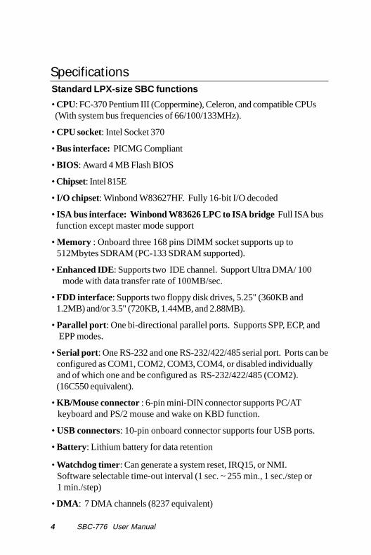
Standard LPX-size SBC functions
• CPU: FC-370 Pentium III (Coppermine), Celeron, and compatible CPUs (With system bus frequencies of 66/100/133MHz).
• CPU socket: Intel Socket 370
• Bus interface: PICMG Compliant
• BIOS: Award 4 MB Flash BIOS
• Chipset: Intel 815E
• I/O chipset: Winbond W83627HF. Fully 16-bit I/O decoded
• ISA bus interface: Winbond W83626 LPC to ISA bridge Full ISA bus function except master mode support
• Memory : Onboard three 168 pins DIMM socket supports up to 512Mbytes SDRAM (PC-133 SDRAM supported).
• Enhanced IDE: Supports two IDE channel. Support Ultra DMA/ 100 mode with data transfer rate of 100MB/sec.
• FDD interface: Supports two floppy disk drives, 5.25" (360KB and 1.2MB) and/or 3.5" (720KB, 1.44MB, and 2.88MB).
• Parallel port : One bi-directional parallel ports. Supports SPP, ECP, and EPP modes.
• Serial port: One RS-232 and one RS-232/422/485 serial port. Ports can be configured as COM1, COM2, COM3, COM4, or disabled individually and of which one and be configured as RS-232/422/485 (COM2). (16C550 equivalent).
• KB/Mouse connector : 6-pin mini-DIN connector supports PC/AT keyboard and PS/2 mouse and wake on KBD function.
• USB connectors: 10-pin onboard connector supports four USB ports.
• Battery: Lithium battery for data retention
• Watchdog timer: Can generate a system reset, IRQ15, or NMI. Software selectable time-out interval (1 sec. ~ 255 min., 1 sec./step or 1 min./step)
• DMA : 7 DMA channels (8237 equivalent)
Specifications

Chapter 1 General Information 5
• Interrupt : 15 interrupt levels (8259 equivalent)
• Power management: Supports ATX power supply. I/O peripheral support power saving and doze/standby/suspend modes. APM 1.2 compliant.
• H/W status monitoring: Embedded in W83267HF supports power, supply voltages, and temperature monitoring.
Flat Panel/CRT Interface
• Chipset: embedded In Intel 815E
• Chipset output VGA signal: AGP 4X
• Display memory: Share system memory 4MB SDRAM (Max)
• Display type: Supports non-interlaced CRT and up to 18/36 bit LCD (TFT, LCD, only). Can display both CRT and Flat Panel simultaneously.
• Resolution: Up to 1024 x 768 @ 256 K colors
Audio Interface
• Chipset: Intel 815E
• Audio interface: One 14 pin header (2.00mm)
• Codec: ALC 200
Ethernet Interface
• Chipset: Intel 815E embedded in ICH2 and Intel 82559ER
• Ethernet interface : 82559ER does not support WOL and AOL
82562ET support WOL and do not support AOL
82562EM support WOL and AOL. 776 offers 82559ER and 82562 ET onboard.
Compact Flash socket onboard
• Compact flash connector onboard support type 2 CFD

6 SBC-776 User Manual
Ultra Wide II SCSI Interface
• Chipset: AdvanSys ASC38C0800
• Connector: 68-pin internal
• Termination: Auto termination
SSD Interface
• One 32-pin DIP socket supports M-Systems DiskOnChip 2000 series
Mechanical and environmental
• Power supply voltage: ATX power supply
• Operating temperature: 32 to 140o F (0 to 60o C)
• Board size: 13.3"(L) x 4.8"(W) (338mm x 122mm)
• Weight: 1.2 lb. (0.3 Kg)
Chapter 1 General Information 7
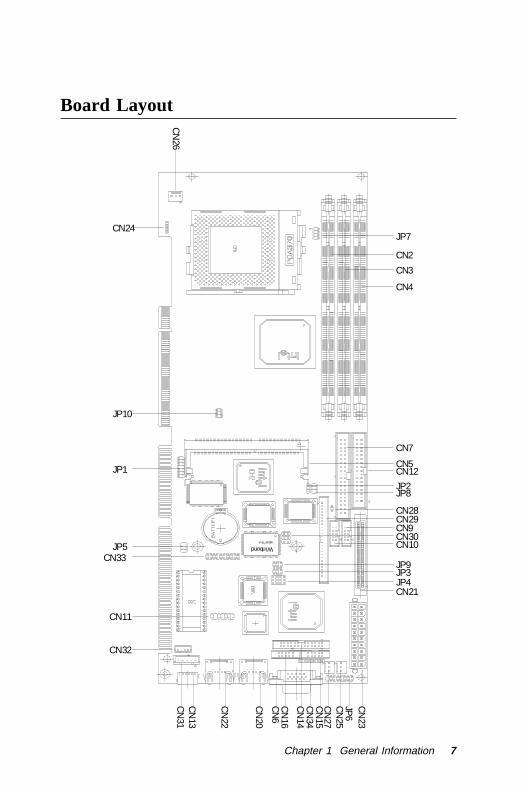
Board Layout
WW83977F-A
CN
26
CN33
CN11
CN32
CN
34C
N15
JP6
CN
25C
N27
CN
23
CN
14
CN
16C
N6
CN
20
JP9
CN21JP4JP3
CN10CN30CN9CN29CN28
JP8JP2
CN12CN5
CN7
CN
22
CN
13C
N31
JP5
JP1
JP10
JP7
CN4
CN3
CN2
CN24inbond

8 SBC-776 User Manual
Board Dimensions
WW83977F-A
inbond

SBC-776 Chapter 2 9
2Installation
This chapter describes how to set up themain board hardware, including instruc-tions on setting jumpers and connectingperipherals, switches, and indicators. Besure to read all the safety precautionsbefore you begin the installation proce-dure.
CH
AP
TE
R

SBC-776
1 0 SBC-776 ManualBC-599/596
Safety precautions
Warning! Always completely disconnect the power cord fromyour chassis whenever you are working on it. Donot make connections while the power is onbecause sensitive electronic components can bedamaged by the sudden rush of power. Onlyexperienced electronics personnel should open thePC chassis.
Caution! Always ground yourself to remove any static charge before touching the CPU card. Modern electronic devices are very sensitive to static electric charges. Use a grounding wrist strap at all times. Place all electronic components on a static-dissipative surface or in a static-shielded bag when they are not in the chassis.
Removing the CPUThe SBC-776 all-in-one CPU module supports most Pentium III/Celeron or 586 CPUs. The system's performance depends on theCPU you choose. You can install or upgrade the CPU in the board'sPGA socket by following the procedures outlined below. If yoursystem has an existing CPU, you need to remove it before installingthe new CPU.
Removing a CPU
1. Disconnect power from the chassis, and unplug all connectionsto the CPU card. Then, remove the CPU card from the chassisby following the instructions in the user's manual for yourchassis.
2. Lift the CPU out of the PGA socket. The old chip may bedifficult to remove. You may find spray chip lubricant, designedfor pin-grid-array (PGA) devices, and a chip puller helpful.These are available at electronics hobbyists' supply stores.

SBC-776 Chapter 2 11
Installing A CPUTo install the CPU, follow the instructions that came with it. If nodocumentation was provided, the general procedures for installinga CPU are outlined below:
1. Lubricate the pins on the CPU with lubricant for PGA devices.This makes the CPU slide in much easier and greatly reducesthe chance of damaging the pins and other components.
2. Carefully align the CPU so that it is parallel to the socket. Makesure that the notch on the corner of the CPU matches the notchon the inside of the socket.
3. Gently push the CPU into the socket. There will probably be asmall gap between the CPU and the socket even when it is fullyseated. DO NOT USE EXCESSIVE FORCE!
When you install a new CPU, you may have to adjust othersettings on the board, such as CPU type, CPU clock, and PCIspeed, to accommodate it. Make sure that the settings are correctfor your CPU. Improper settings may damage the CPU.

SBC-776
1 2 SBC-776 ManualBC-599/596
Installing DRAM (DIMMs)
System Memory
The SBC-776 contains three sockets for 168-pin dual inline memorymodule (DIMM). The socket uses 3.3 V unbuffered synchronousDRAM (SDRAM). DIMM is available in capacities of 16, 32, 64, 128or 256 MB. The socket can be filled in the DIMM of any size,giving your SBC-776 single board computer between 16 and 512MB of memory.
Supplementary information about DIMM
SBC-776 can accept PC-133 SDRAM DIMM Module(with orwithout parity).
Single-sided modules are typically 16 or 64 MB; double-sidedmodules are usually 32, 128 or 256 MB.
Memory Installation Procedures
To install DIMM, first make sure the two handles of the DIMMsocket are in the "open" position. i.e. The handles remain outward.Slowly slide the DIMM module along the plastic guides on bothends of the socket. Then press the DIMM module right down intothe socket, until you hear a click. This is when the two handleshave automatically locked the memory module into the correctposition of the DIMM socket. (See Figure below) To take away thememory module, just push both handles outward, and the memorymodule will be ejected by the mechanism in the socket.

SBC-776 Chapter 2 13
Jumpers
Jumpers Function
JP1 VGA or AGP VGA Select Header
JP2 Clear CMOS Selection
JP3 Watchdog Function Select
JP4 RS-232/422/485 COM 2 Setting
JP5 DiskOnChip Address Selection
JP6 Function Select
JP7 CPU/DIMM Speed Select
JP8 LCD Panel's Voltage Setting
JP9 RS-232/422/485 COM2 Setting
JP10 LCD or VGA Enable Header
SBC-776
1 4 SBC-776 ManualBC-599/596
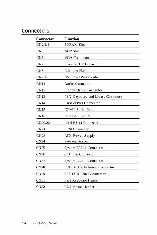
ConnectorsConnector FunctionCN2,3,4 SDRAM Slot
CN5 AGP Slot
CN6 VGA Connector
CN7 Primary IDE Connector
CN8 Compact Flash
CN9,10 USB Dual Port Header
CN11 Audio Connector
CN12 Floppy Drive Connector
CN13 PS/2 Keyboard and Mouse Connector
CN14 Parallel Port Connector
CN15 COM 1 Serial Port
CN16 COM 2 Serial Port
CN20,22 LAN RJ-45 Connector
CN21 SCSI Connector
CN23 ATX Power Supply
CN24 Speaker/Buzzer
CN25 System FAN 1 Connector
CN26 CPU Fan Connector
CN27 System FAN 2 Connector
CN28 LCD Backlight Power Connector
CN29 TFT LCD Panel Connector
CN31 PS/2 Keyboard Header
CN32 PS/2 Mouse Header

SBC-776 Chapter 2 15
Locating Jumpers and Connectors
WW83977F-A
CN
26
CN33
CN11
CN32
CN
34C
N15
JP6
CN
25C
N27
CN
23
CN
14
CN
16C
N6
CN
20
JP9
CN21JP4JP3
CN10CN30CN9CN29CN28
JP8JP2
CN12CN5
CN7
CN
22
CN
13C
N31
JP5
JP1
JP10
JP7
CN4
CN3
CN2
CN24
inbond

SBC-776
1 6 SBC-776 ManualBC-599/596
Locating Jumpers and Connectors
CN8

SBC-776 Chapter 2 17
Mechanical Drawing
WW83977F-A
inbond

SBC-776
1 8 SBC-776 ManualBC-599/596
Mechanical Drawing

SBC-776 Chapter 2 19
VGA or AGP VGA Header Select (JP 1)
Select AGP VGA
1 2 3 4 5 6 7 8 9 10 11 12 13 14
Select on board VGA
1 2 3 4 5 6 7 8 9 10 11 12 13 14
Clear CMOS (JP2)You can use JP2 to clear the CMOS data if necessary. To reset theCMOS data, place a jumper on JP2 for just a few seconds, thenremove the jumper.
Clear CMOS (J2P)
Clear CMOS Protect *
JP2
*default
1 2 3 1 2 3

SBC-776
2 0 SBC-776 ManualBC-599/596
Watchdog Timer Function Select (JP3) The mainboard is equipped with a watchdog timer that resets the CPUor generates an interrupt if processing comes to a standstill for whateverreason. This feature ensures system reliability in industrial stand-aloneand unmanned environments.
Reset
NMI
IRQ15
1 2
1 2
1 2
3 4
3 4
3 4
5 6
5 6
5 6

SBC-776 Chapter 2 21
RS-232/422/485 COM 2 (JP4 & JP9) Setting
*RS-232
1 4 7 10
3 6 9 12
*RS-485
*RS-422
1 4 7 10
3 6 9 12
1 4 7 10
3 6 9 12
The SBC-776 COM 2 serial port can be selected as RS-232/422/485 by setting JP4.
2 4 6
1 3 5
1 3 5
1 3 5
2 4 6
2 4 6

SBC-776
2 2 SBC-776 ManualBC-599/596
DiskOnChip Address Selection (JP5)The DiskOnChip 2000 occupies an 8 Kbyte window in the uppermemory address range of C800 to D400. You should ensure thisdoes not conflict with any other device's memory address. JP5controls the memory address of the Flash Disk.
*D400H
1 3 5
2 4 6*DC00H
1 3 5
2 4 6
*CE00H
1 3 5
2 4 6*D000H
1 3 5
2 4 6

SBC-776 Chapter 2 23
*E000H
1 3 5
2 4 6
*DOC Disable
2 4 6
1 3 5
*D800H
1 3 5
2 4 6
*C800H
1 3 5
2 4 6
These addresses might conflict with the ROM BIOS of otherperipheral boards, Please select the appropriate memoryaddress to avoid memory conflicts.

SBC-776
2 4 SBC-776 ManualBC-599/596
Function Select Header (JP 6)
1 2 Power Button3 4 Reset Switch5 6 Suspend Switch
9 10 Power LED 7 8 Hard Disk LED
11 12 Supend LED 13 14 SCSI LED
15 16 Chassis Open Detected
Speaker
The mainboard can drive an 8Ω external speaker at 0.5 watts. Ifthere is no external speaker, the SBC-776 provides an onboardbuzzer as an alternative.
LED interface
The front panel LED indicator for hard disk access is an active lowsignal (24 mA sink rate).
Next you may want to install external switches to monitor andcontrol the mainboard. These features are completely optional —install them only if you need them. The front panel connector (JP6)is an 16-pin male, dual in-line header and provides connections fora speaker, hard disk access indicator and an input switch forresetting the card.

SBC-776 Chapter 2 25
CPU/DIMM Speed Select Header (JP 7)
CPU/133 DIMM/133
1 2 3 4 5 6 7 8
CPU/133 DIMM/100
1 2 3 4 5 6 7 8
CPU/100 DIMM/100
1 2 3 4 5 6 7 8
CPU/66 DIMM/100
1 2 3 4 5 6 7 8

SBC-776
2 6 SBC-776 ManualBC-599/596
Auto Detect Default
1 2 3 4 5 6 7 8

SBC-776 Chapter 2 27
LCD Panel’s Voltage Setting (JP 8)*LCD Panel power: +5V; Backlight power: +5V
1 3 5
2 4 6
*LCD Panel power: +5V; Backlight power: +12V
1 3 5
2 4 6
*LCD Panel power: +3.3V; Backlight power: +5V
1 3 5
2 4 6
*LCD Panel power: +3.3V; Backlight power: +12V
1 3 5
2 4 6

SBC-776
2 8 SBC-776 ManualBC-599/596
LCD or VGA Enable Header (JP10)
* Default VGA Dual Display
1 3 51 3 5
2 4 6 2 4 6
VGA/LCD Enable
LCD 2PIXS/CLK
VGA Enable
LCD 1PIXS/CLK
VGA connector (CN6)The mainboard's PCI SVGA interface can drive conventional CRTdisplays and is capable of driving a wide range of flat paneldisplays, including electroluminescent (EL), gas plasma, passiveLCD, and active LCD displays. The board has two connectors tosupport these displays, one for standard CRT VGA monitors andone for flat panel displays.
VGA display connector (CN6)
CN6 is a 15-pin, dual-in-line header used for conventional CRTdisplays. A simple one-to-one adapter can be used to match CN6 toa standard 15-pin D-SUB connector commonly used for VGA.
VGA display connector (CN6)
Pin Signal Pin Signal1 RED 9 VCC
2 GREEN 10 GND
3 BLUE 11 N/C
4 N/C 12 DDDA
5 GND 13 H-SYNC
6 GND 14 V-SYNC
7 GND 15 DDCK
8 GND 16 N/C

SBC-776 Chapter 2 29
IDE Hard Drive Connector (CN7)
IDE hard drive connector (CN7)
Pin Signal Pin Signal1 IDE RESET 2 GND
3 DATA 7 4 DATA 8
5 DATA 6 6 DATA 9
7 DATA 5 8 DATA 10
9 DATA 4 10 DATA 11
11 DATA 3 12 DATA 12
13 DATA 2 14 DATA 13
15 DATA 1 16 DATA 14
17 DATA 0 18 DATA 15
19 SIGNAL GND 20 N/C
21 IDEPDREQR 22 GND
23 IO WRITE 24 GND
25 IO READ 26 GND
27 IO CHANNEL READY 28 GND
29 IDEPDACKX 30 GND
31 IRQ14 32 IOCS16
33 ADDR 1 34 P66DET
35 ADDR 0 36 ADDR 2
37 HARD DISK SELECT 0 38 HARD DISK SELECT 1
39 IDE ACTIVE 40 MGND
41 VCC 42 VCC
43 GND 44 N/C

SBC-776
3 0 SBC-776 ManualBC-599/596
USB connector (CN9, CN10)The SBC-776 provides two USB (Universal Serial Bus) interfaces,which give complete plug and play, hot attach/detach for up to 127external devices. The USB interfaces comply with USB specifica-tion Rev. 1.0, and can be disabled in the system BIOS setup.
USB connector (CN9)
Pin Function Pin Function1 VCC 2 GND
3 USBD0- 4 GND
5 UDBD0+ 6 USBD1+
7 GND 8 USBD1-
9 GND 10 VCC
USB connector (CN10)
Pin Function Pin Function1 VCC 2 GND
3 USBD2- 4 GND
5 USBD2+ 6 USBD3+
7 GND 8 USBD3-
9 GND 10 VCC

SBC-776 Chapter 2 31
Audio Connector (CN11)On board SBC-776, there is a 14-pin header for audio capability.The pin definition is provided below.
Audio connector (CN 11)
Pin Signal Pin Signal1 MIC IN 2 MIC VCC3 GND 4 CD IN GND
5 LINE IN L 6 CD IN L I/P
7 LINE IN R 8 CD N GND
9 GND 10 CD IN R I/P
11 LINE OUT L 12 LINE OUT R
13 GND 14 GND

SBC-776
3 2 SBC-776 ManualBC-599/596
Floppy Drive Connector (CN12)
Floppy drive connector (CN12)
Pin Signal Pin Signal 1 GND 2 DENSITY SELECT
3 GND 4 N/C
5 GND 6 DRIVE TYPE
7 GND 8 INDEX
9 GND 10 MOTOR 0
11 GND 12 DRIVE SELECT 1
13 GND 14 DRIVE SELECT 2
15 GND 16 MOTOR 1
17 GND 18 DIRECTION
19 GND 20 STEP
21 GND 22 WRITE DATA
23 GND 24 WRITE GATE
25 GND 26 TRACK 0
27 GND 28 WRITE PROTECT
29 GND 30 READ DATA
31 GND 32 HEAD DELECT
33 GND 34 DISK CHANGE
PS/2 Keyboard and Mouse Connector (CN13)On board SBC-776, there is a standard 6-pin header for PS/2keyboard and mouse connector. The pin definition is providedbelow.
Keyboard and mouse connector (CN 13)
Pin Signal Pin Signal1 KB DATA 2 MS DATA3 GND 4 VCC
5 KB CLOCK 6 MS CLOCK

SBC-776 Chapter 2 33
Parallel port connector (CN14)Normally, the parallel port is used to connect the board to a printer.The SBC-776 includes an onboard parallel port, accessed throughCN14, a 26-pin flat-cable connector. A traditional DB-25 connectorcable is needed to install the printer to the board. The cable has a26-pin connector on one end and a DB-25 connector on the other.
Parallel port IRQ
The onboard parallel port is designated as LPT1 and can bedisabled or changed to LPT2 or LPT3 in the system BIOS setup.
Parallel port connector table (CN14)
Parallel port connector (CN14)
Pin Signal Pin Signal1 /STB 2 D03 D1 4 D25 D3 6 D47 D5 8 D69 D7 10 /ACK
11 BUSY 12 PE
13 SLCT 14 /AUTOFD
15 /ERR 16 /INIT
17 /SLCTINI 18 GND
19 GND 20 GND
21 GND 22 GND
23 GND 24 GND
25 GND 26 N/C

SBC-776
3 4 SBC-776 ManualBC-599/596
COM 1 RS-232 (CN15)
Pin Signal Pin Signal1 SDCDB1X 6 SDSRB1X2 SRXDB1 7 SRTSB1X
3 STXDB1 8 SCTSB1X
4 SDTRB1X 9 SRIB1X
5 GND 10 NC
COM 1 RS-232 (CN16)
Pin Signal Pin Signal1 SDCDB2X 6 SDSRB2X2 SRXDB2 7 SRTSB2X
3 STXDB2 8 SCTSB2X
4 SDTRB2X 9 SRIB2X
5 GND 10 NC
COM 1 (CN 15) & COM 2 (CN 16) Serial Ports
On board offer four set serial ports for serial devices connection.Two of them are the D-Sub type, pin definition show as below, foranother two, please refer to page ?.

SBC-776 Chapter 2 35
SCSI-2 68-PinConnector (CN 21)SBC-776 has a 68 pin connector for the Ultra 2 SCSI connection.Please pay attention when connecting the SCSI device, becauseyou must determine the last device on the SCSI chain.
PIN FUNCTION PIN FUNCTION1 SD+12 35 SD-122 SD+13 36 SD-133 SD+14 37 SD-144 SD+15 38 SD-155 SDP+1 39 SDP-16 SD+0 40 SD-07 SD+1 41 SD-18 SD+2 42 SD-29 SD+3 43 SD-310 SD+4 44 SD-411 SD+5 45 SD-512 SD+6 46 SD-613 SD+7 47 SD-714 SDP + 0 48 SDP - 015 GND 49 GND16 DIFS 50 SENIN17 TPWEX 51 TPWEX18 TPWEX 52 TPWEX19 NC 53 NC20 GND 54 GND21 SATN+ 55 SATN-22 GND 56 GND23 SBSY+ 57 SBSY-24 SACK+ 58 SACK-25 SRST+ 59 SRST-26 SMSG+ 60 SMSG-27 SSEL+ 61 SSEL-28 SCD + 62 SCD-29 SREQ+ 63 SREQ-30 SIO+ 64 SIO-31 SD+8 65 SD-832 SD+9 66 SD-933 SD+10 67 SD-1034 SD+11 68 SD-11

SBC-776
3 6 SBC-776 ManualBC-599/596
100Base-Tx LAN connector (CN22,20)
Green LED: 100M LAN speed
Yellow LED: 10M LAN speed
100Base-Tx Ethernet connector (CN22)
Pin Signal Pin Sig1 Tx+ 5 N/C2 TX- 6 RX-
3 RX+ 7 N/C
4 N/C 8 N/C
Green LED: 100M LAN speed
Yellow LED: 10M LAN speed
100Base-Tx Ethernet connector (CN20)
Pin Signal Pin Sig1 Tx+ 5 N/C2 TX- 6 RX-
3 RX+ 7 N/C
4 N/C 8 N/C
On board supports one standard RJ-45 connector for enthernetconnection. The RJ-45 connector has two LED indicators. BothLED displays indicate the speed of information being processed,however the Lan speed does vary.
* The on board Intel 82559XX fast ethernet controller supports10Mb/s and 100Mb/s N-way auto-negotiation operation.
SBC-776 Chapter 2 37
1 2 3 4
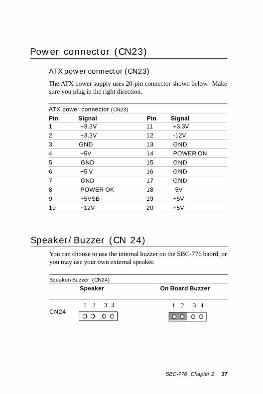
Power connector (CN23)
ATX power connector (CN23)
The ATX power supply uses 20-pin connector shown below. Makesure you plug in the right direction.
ATX power connector (CN23)
Pin Signal Pin Signal1 +3.3V 11 +3.3V
2 +3.3V 12 -12V
3 GND 13 GND
4 +5V 14 POWER ON
5 GND 15 GND
6 +5 V 16 GND
7 GND 17 GND
8 POWER OK 18 -5V
9 +5VSB 19 +5V
10 +12V 20 +5V
Speaker/Buzzer (CN 24)You can choose to use the internal buzzer on the SBC-776 baord, oryou may use your own external speaker.
Speaker/Buzzer (CN24)
Speaker On Board Buzzer
CN241 2 3 4

SBC-776
3 8 SBC-776 ManualBC-599/596
Fan power connectors (CN25, 26, 27)
CPU fan power connector (CN 26)
Plug in the fan cable to the 3-pin fan connector onboard. The fanconnector is marked CN26.
CPU fan power connector (CN26)
Pin Signal1 GND
2 +12V
3 Fan speed sensor
System fan 1 connector (CN 25)
Pin Signal1 GND
2 +12V
3 Fan speed sensor
System fan 2 connector (CN27)
Pin Signal1 GND
2 +12V
3 Fan speed sensor

SBC-776 Chapter 2 39
TFT LCD panel connector (CN 29)LCD panel connector (CN 29)
Pin Signal Pin Signal1 BLKVCC 2 BLKVCC3 GND 4 GND5 LDCVCC 6 LCDVCC7 ENAVEE 8 GND9 P0 10 P111 P2 12 P313 P4 14 P515 P6 16 P717 P8 18 P919 P10 20 P1121 P12 22 P1323 P14 24 P1525 P16 26 P1727 P18 28 P1929 P20 30 P2131 P22 32 P2333 P24 34 P2535 SHF CLK 36 VSYNC37 DE 38 HSYNC39 GND 40 FPBLEN41 P26 42 P2743 P28 44 P2945 P30 46 P3147 P32 48 P3349 P34 50 P35
LCD Backlight Power Connector (CN 28) LCD Backlight Power Connector (CN 28) Pin Signal 1 BLKVCC 2 GND

SBC-776
4 0 SBC-776 ManualBC-599/596
PS/2 Keyboard Header (CN31)Onboard there is a 5-pin header for keybaord connection, the pindefinition is provided below.
PS/2 Keyboard Header (CN 31)
Pin Signal Pin Signal1 KB CLOCK 2 KB DATA3 NC 4 GND
5 VCC
PS/2 Mouse Header (CN 32)Onboard there is a 4-pin header for keyboard connection, the pindefinition is provided below.
PS/2 Mouse Header (CN 32)
Pin Signal Pin Signal1 MS CLOCK 2 MS DATA3 GND 4 VCC

42 SBC-776 User Manual
3Award BIOS Setup
This chapter describes how to configurethe BIOS for the system.
CH
AP
TE
R

Chapter 3 Award BIOS Setup 43
Starting setupThe Award BIOS is immediately activated when you first turn onthe computer. The BIOS reads system configuration information inCMOS RAM and begins the process of checking out the systemand configuring it through the power-on self test (POST).
When these preliminaries are finished, the BIOS seeks an operatingsystem on one of the data storage devices (hard drive, floppy drive,etc.). The BIOS launches the operating system and hands control ofsystem operations to it.
During POST, you can start the Setup program in one of two ways:1.By pressing Del immediately after switching the system on, or2.By pressing Del or pressing Ctrl-Alt-Esc when the followingmessage appears briefly at the bottom of the screen during POST:
TO ENTER SETUP BEFORE BOOT PRESS DEL KEY
If the message disappears before you respond and you still wish toenter Setup, restart the system to try again by turning it OFF thenON or pressing the RESET button on the system case. You mayalso restart by simultaneously pressing Ctr-Alt-Del. If you do notpress the keys at the correct time and the system does not boot, anerror message appears and you are again asked to
PRESS F1 TO CONTINUE, DEL TO ENTER SETUP

44 SBC-776 User Manual
Setup keysThese keys helps you navigate in Award BIOS:
Up arrow Move to previous itemDown arrow Move to next itemLeft arrow Move to the item in the left handRight arrow Move to the item in the right handEsc Main Menu: Quit and not save changes into CMOS RAM
Other pages: Exit current page and return to Main MenuPgUP/+ Increase the numeric value or make
changesPgDn/- Decrease the numeric value or make
changesF1 General help, only for Status Page Setup
Menu and Option Page Setup MenuF2 Item HelpF3 ReservedF4 ReservedF5 Restore the previous CMOS value from
CMOS, only for Option Page Setup MenuF6 Load the default CMOS RAM value from
BIOS default table, only for Option PageSetup Menu
F7 Load the defaultF8 ReservedF9 ReservedF10 Save all the CMOS changes, only for Main
Menu

Chapter 3 Award BIOS Setup 45
Getting helpPress F1 to pop up a small help window that describes the appro-priate keys to use and the possible selections for the highlighteditem. To exit the Help Window press Esc or the F1 key again.
In Case of Problems
If, after making and saving system changes with Setup, youdiscover that your computer no longer is able to boot, the AwardBIOS supports an override to the CMOS settings that resets yoursystem to its default configuration.
You can invoke this override by immediately pressing Insert; whenyou restart your computer. You can restart by either using the ON/OFF switch, the RESET button or by pressing Ctrl-Alt-Delete.
The best advice is to alter only settings that you thoroughlyunderstand. In particular, do not change settings in the Chipsetscreen without a good reason. The Chipset defaults have beencarefully chosen by Award Software or your system manufacturerfor the best performance and reliability. Even a seemingly smallchange to the Chipset setup may cause the system to becomeunstable.

46 SBC-776 User Manual
Main Setup Menu
Standard CMOS FeaturesUse this menu for basic system configuration. (Date, time, IDE,
etc.)
Advanced BIOS FeaturesUse this menu to set the advanced features available on your
system.
Advanced Chipset FeaturesUse this menu to change the values in the chipset registers and
optimize your system’s performance.
Integrated PeripheralsUse this menu to specify your settings for integrated peripherals.
(Primary slave, secondary slave, keyboard, mouse etc.)
Power Management SetupUse this menu to specify your settings for power management.
(HDD power down, power on by ring, KB wake up, etc.)

Chapter 3 Award BIOS Setup 47
PnP/PCI ConfigurationThis entry appears is your system supports PnP/PCI.
PC Health StatusThis menu allows you to set the shutdown temperature for yoursystem.
Frequency/Voltage ControlUse this menu to specify your settings for frequency/ voltagecontrol.
Load Fail-Safe DefaultsUse this menu to load the BIOS default values for the minimal/stable performance for your system to operate.
Load Optimized DefaultsUse this menu to load the BIOS default values that are factorysettings for optimal performance system operations. WhileAWARD has designated the custom BIOS to maximize perfor-mance, the factory has the right to change these defaults to meettheir needs.
Set Supervisor/User PasswordUse this menu to set User and Supervisor Passwords.
Save and Exit SetupSave CMOS value changes to CMOS and exit setup.
Exit Without SavingAbandon all CMOS value changes and exit setup.

48 SBC-776 User Manual
Standard CMOS Features
This standard setup menu allows users to configure systemcomponents such as the date, time, hard disk drive, floppy drive,display, and memory. Online help for each field can be accessedby pressing F1.
Date and Time ConfigurationThe BIOS determines the day of the week from the other dateinformation. This field is for information only.
Press the left or right arrow key to move to the desired field (date,month, year). Press the PgUp/- or PgDn/+ key to increment thesetting, or type the desired value into the field.
The time format is based on the 24-hour military-time clock. Forexample, 1 p.m. is 13:00:00 hours. Press the left or right arrow keyto move to the desired field. Press the PgUp/- or PgDn/+ key toincrement the setting, or type the desired value into the field.
HARD DISKSThe BIOS supports up to four IDE drives. This section does notshow information about other IDE devices, such as a CD-ROMdrive, or about other hard drive types, such as SCSI drives.
NOTE: We recommend that you select type AUTO for all drives.

Chapter 3 Award BIOS Setup 49
If you do not want to select drive type AUTO, other methods ofselecting the drive type are available:
1.Match the specifications of your installed IDE hard drive(s) with the preprogrammed values for drive types 1 through 45.
2.Select USER and enter values into each drive parameter field.
3.Use the IDE HDD AUTO DETECTION function in Setup.
Here is a brief explanation of drive specifications:
Type: The BIOS contains a table of predefined drive types. Each defined drive type has a specified number of cylinders,
number of heads, write precompensation factor, landing zone, and number of sectors. Drives whose specifications do not accommodate any predefined type are classified as type USER.
Size: Disk drive capacity (approximate). Note that this size is usually slightly greater than the size of a formatted disk given by a disk-checking program.
Cyls: Number of cylinders
Head: Number of heads
Precomp: Write precompensation cylinder
Landz: Landing zone
Sector: Number of sectors
Mode: Auto, Normal, Large, or LBA
- Auto: The BIOS automatically determines the optimal mode.
- Normal: Maximum number of cylinders, heads, and sectors supported are 1024, 16, and 63.
- Large: For drives that do not support LBA and have more than 1024 cylinders.
The BIOS can automatically detect the specifications and optimaloperating mode of almost all IDE hard drives. When you selecttype AUTO for a hard drive, the BIOS detects its specifications

50 SBC-776 User Manual
- LBA (Logical Block Addressing): During drive access, theIDE controller transforms the data address described bysector, head, and cylinder number into a physical block address,significantly improving data transfer rates. For drives with greaterthan 1024 cylinders.
Drive ADrive BSelect the correct specifications for the diskette drive(s) installed inthe computer.
None No diskette drive installed360K, 5.25 in 5-1/4 inch PC-type standard drive;
360 kilobyte capacity1.2M, 5.25 in 5-1/4 inch AT-type high-density
drive; 1.2 megabyte capacity720K, 3.5 in 3-1/2 inch double-sided drive;
720 kilobyte capacity1.44M, 3.5 in 3-1/2 inch double-sided drive;
1.44 mega byte capacity2.88M, 3.5 in 3-1/2 inch double-sided drive;
2.88 mega byte capacity
VideoSelect the type of primary video subsystem in your computer. TheBIOS usually detects the correct video type automatically. TheBIOS supports a secondary video subsystem, but you do not selectit in Setup.
EGA/VGA Enhanced Graphics Adapter/Video Graphics Array.For EGA, VGA, SEGA, SVGA, or PGA monitor adapters.
CGA 40 Color Graphics Adapter, power up in 40 column mode
CGA 80 Color Graphics Adapter, power up in 80 column mode
MONO Monochromoe adapter, includes high resolution monochrome adapters

Chapter 3 Award BIOS Setup 51
Halt OnDuring the power-on-self-test (POST), the computer stops if theBIOS detects a hardware error. You can tell the BIOS to ignorecertain errors during POST and continue the boot-up process.These are the selections:
No errors: POST does not stop for any errors.
All errors If : the BIOS detects any nonfatal error, POSTstops and prompts you to take corrective action.
All, But Keyboard : POST does not stop for a keyboarderror, but stops for all other errors
All, But Diskette: POST does not stop for diskette driveerrors, but stops for all other errors.
All, But Disk/Key : POST does not stop for a keyboard ordisk error, but stops for all other errors.
MemoryYou cannot change any values in the Memory fields; they are onlyfor your information. The fields show the total installed randomaccess memory (RAM) and amounts allocated to base memory,extended memory, and other (high) memory. RAM is counted inkilobytes (KB: approximately one thousand bytes) and megabytes(MB: approximately one million bytes).
RAM is the computer's working memory, where the computerstores programs and data currently being used, so they are accessi-ble to the CPU. Modern personal computers may contain up to 64MB, 128 MB, or more.
Base MemoryTypically 640 KB. Also called conventional memory. The DOSoperating system and conventional applications use this area.

52 SBC-776 User Manual
Extended MemoryAbove the 1-MB boundary. Early IBM personal computers couldnot use memory above 1 MB, but current PCs and their softwarecan use extended memory.
Other MemoryBetween 640 KB and 1 MB; often called High memory. DOS mayload, terminate-and-stay-resident (TSR) programs, such as devicedrivers, in this area, to free as much conventional memory aspossible for applications. Lines in your CONFIG.SYS file that startwith LOADHIGH, load programs into high memory.

Chapter 3 Award BIOS Setup 53
Advanced BIOS Features
The displayed configuration is based on the manufacturer's SETUPDEFAULTS settings.
Virus WarningWhen enabled, you receive a warning message if a program(specifically, a virus) attempts to write to the boot sector or thepartition table of the hard disk drive. You should then run an anti-virus program. Keep in mind that this feature protects only the bootsector, not the entire hard drive.
NOTE: Many disk diagnostic programs that access the boot sectortable can trigger the virus warning message. If you plan to runsuch a program, we recommend that you first disable the viruswarning.

54 SBC-776 User Manual
CPU Internal Cache/External CacheCache memory is additional memory that is much faster thanconventional DRAM (system memory). CPUs from 486-type on upcontain internal cache memory, and most, but not all, modern PCshave additional (external) cache memory. When the CPU requestsdata, the system transfers the requested data from the main DRAMinto cache memory, for even faster access by the CPU.
The External Cache field may not appear if your system does nothave external cache memory.
CPU L2 Cache ECC CheckingWhen you select Enabled, memory checking is enable when theexternal cache contains ECC SRAMs.
Processor Number FeatureThis option is for Pentium III processor. During Enabled, this willcheck the CPU Serial number. Disabled this option if you don'twant the system to know the serial number.
Quick Power On Self TestSelect Enabled to reduce the amount of time required to run thepower-on-self-test (POST). A quick POST skips certain steps. Werecommend that you normally disable quick POST. Better to find aproblem during POST than lose data during your work.
First/Second/Third/Fourth Boot DeviceThe BIOS attempts to load the operating system from the devicesin the sequence selected in these items.
The choices: Floppy, LS/ZIP, HDD, SCSI, CDROM, Disable.

Chapter 3 Award BIOS Setup 55
Swap Floppy DriveThis field is effective only in systems with two floppy drives.Selecting enabled assigns physical drive B to logical drive A, andphysical drive A to logical drive B.
Boot Up Floppy SeekWhen Enabled, the BIOS tests (seeks) floppy drives to determinewhether they have 40 or 80 tracks. Only 360-KB floppy driveshave 40 tracks; drives with 720 KB, 1.2 MB, and 1.44 MBcapacity all have 80 tracks. Because very few modern PCs have40-track floppy drives, we recommend that you set this field toDisabled to save time.
Boot Up NumLock StatusToggle between On or Off to control the state of the NumLock keywhen the system boots. When toggled On, the numeric keypadgenerates numbers instead of controlling cursor operations.
Gate A20 OptionGate A20 refers to the way the system addresses memory above 1MB (extended memory). When set to Fast, the system chipsetcontrols Gate A20. When set to Normal, a pin in the keyboardcontroller controls Gate A20. Setting Gate A20 to Fast improvessystem speed, particularly with OS/2 and Windows.
56 SBC-776 User Manual
Typematic Rate Setting- Key strokes repeat at arate determined by the keyboard controller. Whenenabled, the typematic rate and typematic delay can beselected.
The choice: Enabled/Disabled
Security Option If you have set a password, select whether the password is required every time the System boots, or only when you enter
Setup.
OS Select For DRAM>64MB-Select theoperating system that is running with greater than 64MBor RAM on the system.
The choice: Non-OS2, OS2

Chapter 3 Award BIOS Setup 57
HDD S.M.A.R.T CapabilityHard disk drives have built in problem detectioncapability (Self-Monitoring Analysis and Reporting Technology).If a foreseen problem is about to take place, the computer will
give a you a warning signal. The choice: Enable, Disable
Report No FDD For WIN 95- Reportno FDD for Win 95 or not. The choice: Yes, no

58 SBC-776 User Manual
Advanced Chipset Features
SDRAM CAS Latency TimeWhen synchronous DRAM is installed, the number of clock cycles ofCAS latency depends on the DRAM timing. Do not reset this field from
the default value specified by the system designer.
SDRAM Cycle Time Tras/TrcSelect the number of SCLKs for an access cycle.The choices: 5/7, 7/9 disable.
SDRAM RAS-to-CAS DelayThis field lets you insert a timing delay between the CAS and RAS strobesignals, used when DRAM is written to, read from, or refreshed. Fastgives faster performance; slow gives more stable performance. This fieldapplies only when synchronous DRAM is installed in the system.

Chapter 3 Award BIOS Setup 59
SDRAM RAS Precharge TimeIf an insufficient number of cycles is allowed for the RAS to accumulateits charge before DRAM refresh, the refresh may be incomplete and theDRAM may fail to retain date. Fast gives faster performance; slow givesmore stable performance. This field applies only when synchronous
DRAM is installed in the system.
System BIOS CacheableSelecting Enabled allows caching of the system BIOS ROM at F0000h-FFFFFh, resulting in better system performance. However, if any programwrites to this memory area, a system error may result. The choices:
Enabled, Disabled
Video BIOS CacheableSelecting Enabled allows caching of the video BIOS ROM at C0000h toC7FFFh, resulting in better video performance. However, if any programwrites to this memory area, a system error may result. The choices:Enabled, Disabled Memory
Hole At 15-16mIn order to improve performance, certain space in memory is reserved forISA cards. This memory must be mapped into the memory. The choices:
15-16 M, disabled
CPU Latency TimerDuring enable, a deferrable CPU cycle will only be Deferred after it hasbeen in Snoop Stall for 31 clocks and another ADS# has arrived. Duringdisable, a deferrable CPU cycle will be deferred immediately after the
GMCH receives another ADS#.
Delayed TransactionThe chipset has an embedded 32-bit posted write buffer to support delaytransactions cycles. Select Enabled to support compliance with PCIspecification version 2.1.
60 SBC-776 User Manual
AGP Graphics Aperture SizeSelect the size of Accelerated Graphics Port (AGP) aperture. Theaperture is a portion of the PCI memory address range dedicated forgraphics memory address space. Host cycles that hit the aperture rangeare forwarded to the AGP without any translation. The choices: 32M,64M.
Display Cache FrequencyDisplay cache frequency will allow for the level the of the share memoryprovided by the Intel 815E chipset to be adjusted.
The settings are 100MHz and 133 MHz.
System Memory FrequencySelect the onboard display cache frequency. The settings are auto,
100MHz and 133MHz.
On-Chip Video Window SizeSelect the on-chip video window size for VGA drive use.The choices: 32MB, 64MB, Disabled
Initial Display CacheCas# LatencySelect the local memory clock period. The number ofclock cycles of CAS# Latency depends on the OnboardDisplay Cache timing. The choice: 2,3Paging Mode ControlSelect the paging mode control. The choice: open,closeRAS-to-CAS OverrideThis item allows you to insert a timing delay between theCAS and RAS strobe signals, used when Onboarddisplay cache is written to, read from, or refreshed.During by CAS#LT, this will depend on the OnboardDisplay Cache CAS# Latency setting. During Override(2), RAS-to-CAS time = 2Ras# TimingThis item controls RAS# active to Precharge, and refreshto RAS# active delay ( in local memory clock ). Thechoices: Fast, SlowRas# Precharge TimingThis item controls RAS# precharge ( in loca memoryclocks). The choices: Fast, slow
Chapter 3 Award BIOS Setup 61
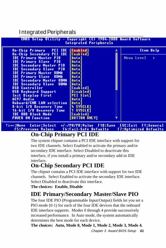
Integrated Peripherals
On-Chip Primary PCI IDEThe system chipset contains a PCI IDE interface with support fortwo IDE channels. Select Enabled to activate the primary and/orsecondary IDE interface. Select Disabled to deactivate thisinterface, if you install a primary and/or secondary add-in IDEinterface.On-Chip Secondary PCI IDEThe chipset contains a PCI IDE interface with support for two IDEchannels. Select Enabled to activate the secondary IDE interface.Select Disabled to deactivate this interface.The choices: Enable, Disable
IDE Primary/Secondary Master/Slave PIOThe four IDE PIO (Programmable Input/Output) fields let you set aPIO mode (0-1) for each of the four IDE devices that the onboardIDE interface supports. Modes 0 through 4 provide successivelyincreased performance. In Auto mode, the system automaticallydetermines the best mode for each device.The choices: Auto, Mode 0, Mode 1, Mode 2, Mode 3, Mode 4.

62 SBC-776 User Manual
IDE Primary/Secondary Master/Slave UDMAUltra DMA/33 implementation is possible only if your IDE harddrive supports it and the operating environment includes a DMAdriver (Windows 95 OSR2 or a third-party IDE bus master driver).If your hard drive and your system software both support UltraDMA/33, select Auto to enable BIOS support.
The choices: Auto, disable
USB ControllerSelect Enabled if your system contains a Universal Serial Buscontroller and you have USB peripherals.
USB Keyboard SupportSelect Enabled if your system contains a Universal Serial Bus
controller and you have a USB keyboard.
Init Display FirstThis item allows you to active PCI slot or onboard first.
The choice: PCI slot, onboard
AC97 AudioThe default setting of Auto enables the AC97 audio if it is detectedonboard
Onboard/CRN LAN selection
Testing purposes only. Leave this function in the AUTO setting.
8-bit I/O Recovery TimeThe I/O recovery mechanism adds bus clock cycles between PCI-originated I/O cycles to the ISA bus. This delay takes placebecause the PCI bus is much faster than the ISA bus. This fieldlets you add recovery time (in bus clock cycles) for 8-bit I/O.
The choice: 0-7 SYSCLK

Chapter 3 Award BIOS Setup 63
16-bit I/O Recovery TimeThe I/O recovery mechanism adds bus clock cycles between PCI-originated I/O cycles to the ISA bus. This delay takes placebecause the PCI bus is much faster than the ISA bus. This fieldlets you add recovery time (in bus clock cycles) for 16-bit I/O.
The choice: 1 SYSCLK, 2SYSCLK, 3SYSCLK, 4 SYSCLK
IDE HDD Block ModeBlock mode is also called block transfer, multiple commands, ormultiple sector read/write. If your IDE hard drive supports blockmode (most new drives do), select Enabled for automatic detectionof the optimal number of block read/write per sector the drive cansupport.
Power on FunctionSelect the different manners for powering on the system.The choices: Keyboard 98, password, any key, hot key, button
only, mouse click, mouse move.
KB Power on PasswordThe system will ask for a password, after entering the correct
password the keyboard can then be used.
Ir Transmission DelayThe system IR component transmits and retrieves data from itsworking environment, if enabled the IR system will detect ortransmit information. If disabled the IR system will be unable to
operate.
Use IR PinsConsult your IR peripheral documentation to select the correctsetting of the TxD and RxD signals.

64 SBC-776 User Manual
Onboard FDC ControllerSelect Enabled if your system has a floppy disk controller (FDC)installed on the system board and you wish to use it. If you installan add-in FDC or the system has no floppy drive, select Disabledin this field.
UART Mode SelectSelect an operating mode for the second serial port:
Normal RS-232C serial port
IrDA 1.0 Infrared port compliant with IrDA 1.0
specification
IrDA SIR IrDA-compliant serial infrared port
IrDA MIR 1 MB/sec infrared port
IrDA FIR Fast infrared standard
ASK IR Amplitude shift keyed infrared port
SCR
Hot Key Power OnSimply pressing on the pre-selected keyboard key the system willpower on.
RxD, TxD ActiveConsult your IR peripheral documention to select the correct
setting of the TxD and RxD signals
UR2 Duplex ModeSelect the value required by the IR device connected to the IR prot.Full-duplex mode permits simultaneous two-direction transmission.Half-duplex mode permits transmission in one direction only at a
time. If no infrared port is present in the system, select disabled.
Use IR PinsConsult your IR peripheral documentation to select the correctsetting of the TxD and RxD signals.

Chapter 3 Award BIOS Setup 65
Onboard Serial Ports (1, 2)Normally, the main board’s I/O chips will occupy a certain portionof memory space. For each I/O device the computer provides anI/O address. The more devices attached the more address neededto organize the memory storage areas. If all the I/O devices wererun through the same address, your devices would come to a nearhalt. By providing the end user with four serial ports this allowsdevices to run more efficiently if needed. Also the correspondinginterrupt needs to be selected.
Selections of logical COM port addresses are as follows. ( 3F8/IRQ4, 3E8/IRQ4, 2F8/IRQ3, 2E8/IRQ3)
Onboard Parallel PortSelect a logical LPT port address and corresponding interrupt forthe physical parallel port
The Choice: 378/IRQ7, 278/IRQ5, 3BC/IRQ7, disabled
Parallel Port ModeTwo bidirectional parallel ports. Supports SPP, ECP, EPP,ECP + EPP.
EPP Mode SelectSelect the EPP port type 1.7 or 1.9
ECP Mode Use DMASelect a DMA channel for the port.
PWRON After PWR-FailThis option will determine how the system will power on after apower failure.
The choice: off, on , former status

66 SBC-776 User Manual
Watch Dog TimerYou can enable the system watchdog timer, a hardware timer thatgenerates either an NMI or a reset when the software that itmonitors does not respond as expected each time the watch dogpolls it ( select the time period in a separate field ) The choice:Disabled, 20 sec, 30 sec, 40 sec, 50 sec, 1 min, 2 min, 4 min.

Chapter 3 Award BIOS Setup 67
Power Management Setup
ACPI FunctionThis item allows you to enable/disable the Advanced Configuration
and Power Management (ACPI). The Choices: Enable/Disable
ACPI Suspend TypeThis item will set which ACPI suspend type will be used.
S1 (POS) The S1 sleeping state is low wake-up latency sleepingstate. In this state, no system context is lost (CPU or chip set) andhardware maintains all system context.
S3 (STR) The S3 state is a low wake-up latency sleeping statewhere all system context is lost expect system memory. CPU,cache and chipset context are lost in this state. Hardware maintainsmemory context and restores some CPU and L2 configurationcontext.
68 SBC-776 User Manual
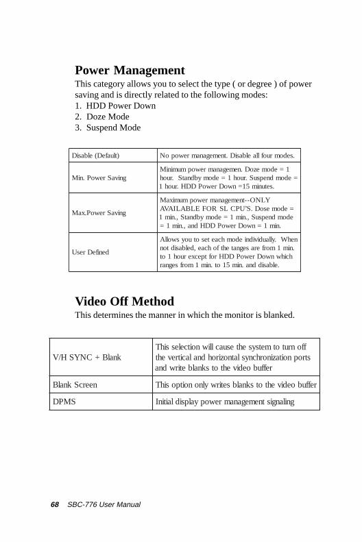
Power ManagementThis category allows you to select the type ( or degree ) of powersaving and is directly related to the following modes:1. HDD Power Down2. Doze Mode3. Suspend Mode
)tluafeD(elbasiD .sedomruofllaelbasiD.tnemeganamrewopoN
gnivaSrewoP.niM1=edomezoD.nemeganamrewopmuminiM
=edomdnepsuS.ruoh1=edomybdnatS.ruoh.setunim51=nwoDrewoPDDH.ruoh1
gnivaSrewoP.xaM
--tnemeganamrewopmumixaM YLNO.S’UPCLSROFELBALIAVA =edomesoD
edomdnepsuS,.nim1=edomybdnatS,.nim1.nim1=nwoDrewoPDDHdna,.nim1=
denifeDresU
nehW.yllaudividniedomhcaetesotuoyswollA.nim1morferasegnatehtfohcae,delbasidton
hcihwnwoDrewoPDDHroftpecxeruoh1ot.elbasiddna.nim51ot.nim1morfsegnar
Video Off MethodThis determines the manner in which the monitor is blanked.
knalB+CNYSH/VffonrutotmetsysehtesuaclliwnoitcelessihTstropnoitazinorhcnyslatnozirohdnalacitreveht
reffuboedivehtotsknalbetirwdna
neercSknalB reffuboedivehtotsknalbsetirwylnonoitposihT
SMPD gnilangistnemeganamrewopyalpsidlaitinI

Chapter 3 Award BIOS Setup 69
Video Off In SuspendAfter the selected period of system inactivity, the chipset enters ahardware suspend mode, stopping the CPU clock and possiblycausing other system devices to enter power management modes.In this case the video hardware can be selected to shut off after aperiod of system inactivity. This determines the manner in which
the monitor is blanked.
Suspend TypeSelect the suspend type. The choice: PWRON suspend, Stop
Grant
MODEM use IRQThis determines the IRQ in which the MODEM can use.
The choices: 3, 4, 5, 7, 9, 10, 11, NA
Suspend ModeAfter the selected period of system inactivity, the chipset enters ahardware suspend mode, stopping the CPU clock and possiblycausing other system devices to enter power management modes.
Soft-Off by PWR-BTTNPressing the power button for more than 4 seconds forces thesystem to enter the Soft-Off state when the system has hung. The
choice: Delay 4 seconds, Instant-Off.
Wake Up On PCI CardThis will enable the system to wake up through PCI cardperipheral. The choice: Enable/Disable
Power On By RingAn input signal on the serial Ring Indicator (RI) line (in otherwords, an incoming call on the modem) boots the system from asoft off state.

70 SBC-776 User Manual
USB KB Wake-up From S3This option is used to Enabled/Disabled USB keyboard wake up
with suspend to RAM. The Choice: Enabled/Disabled
Power On after Power FailAfter initial power failure, the system will attempt to power upagain in the setting that the end user has selected.
The Choice: ON/OFF/Former status
CPU Thermal-ThrottlingSelect the CPU Thermal-Throttling rate for your system.The choice: 12.5%, 25%, 37.5%, 50%, 62.5% 75%, 87.5%
Resume By AlarmThis option is used to Enable/Disable USB keyboard wake up withsuspend to RAM.The choices: Enable, disable
Date AlarmYou can choose which month the system will boot up. Set to 0 toboot everyday.Time AlarmYou can choose what hour, minute and second the system will bootup.

Chapter 3 Award BIOS Setup 71
<Reload Global Timer Events> PM events are I/O events whose occurrence can prevent
the system from entering a power saving mode or canawaken the system from such a mode. In effect, thesystem remains alert for anything which occurs to a devicewhich is configured as Enabled, even when the system isin a power down mode.
Primary IDE 0Primary IDE 1Secondary IDE 0Secondary IDE 1FDD, COM, LPT PortPCI PIRQ (A-D)#

72 SBC-776 User Manual
PnP/PCI Configurations
Reset Configuration DataNormally, you leave this field disabled. Select enabled to resetExtended System Configuration Data (ESCD) when you exit Setupif you have installed a new add-on and the system reconfigurationhas caused such a serious conflict that the operating system can notboot. The choices: Enabled, Disabled
PNP OS InstalledThis item allows you to determine whether the PnP OS is installedor not. Select Yes if the system operating environment is Plug andPlay aware. The settings are Yes or No.

Chapter 3 Award BIOS Setup 73
Resources Controlled ByThe Award Plug and Play BIOS has the capacity to automaticallyconfigure all of the boot and Plug and Play compatible devices.However, this capability means absolutely nothing unless you areusing a Plug and Play operating system such as Windows ® 95. Ifyou set this field to “manual” choose specific resources by goinginto each of the sub menu that follows this field ( a sub menu isproceeded by a “>”. The choices: Auto, Manual.
PCI/VGA Palette SnoopLeave this field at Disabled. Choices: Enabled, Disabled.

74 SBC-776 User Manual
PC Health Status
CPU Warning TemperatureDuring enabled, this will warn the user when the CPU temperaturereach a certain temperature.
Options: Disabled, 75°C/167°F, 70°C/158°F, 65°C/149°F, 60°C/140°F
Shutdown TemperatureYour system can be configured to shutdown once reaching a certaintemperature. To protect your system from overheating or damage,select a certain temperature level in the PC Health Status menu.
Options: Disabled, 75°C/167°F, 70°C/158°F, 65°C/149°F, 60°C/140°F

Chapter 3 Award BIOS Setup 75
Frequency/Voltage Control
Auto Detect DIMM/PCI CLKThis item allows you to enable/disable auto detect DIMM/PCI
clock. The choices: Enable/Disable
Spread SpectrumThis allows you to enable/disable the spread spectrum modulate.When the system clock generator pulses, the extreme values of thepulse generate excess EMI. Enabling pulse spectrum spreadmodulation changes the extreme pulse spikes to flat curves thusreducing EMI.
The choices: Enable, Disable
Clock By Slight AdjustThis item allows you to select the CPU clock from 166 MHz to100 MHz or 99 MHz to 66 MHz depending on the CPU host
clock.
CPU Clock RatioThis item allows you to select the CPU ratio. When using an IntelCPU this item will be hidden.

76 SBC-776 User Manual
Load Fail-Safe Defaults
Load Fail-Safe DefaultsWhen you press <Enter> on this item you get a confirmation dialogbox with a message similar to:
Load Fail-Safe Default (Y/N)?
Pressing “Y” loads the BIOS default values for the most stable,minimal performance system operations.

Chapter 3 Award BIOS Setup 77
Load Optimized Default
Load Optimized DefaultWhen you press <Enter> on this item you get a confirmation dialogbox with a message similar to:
Load Optimized Defaults (Y/N)?
Pressing “Y” loads the default values that are factory settings foroptimal performance system operations

78 SBC-776 User Manual
Set Supervisor Password
When you select this function, a message appears at the center ofthe screen:
ENTER PASSWORD:
Type the password, up to eight characters, and press Enter. Typinga password clears any previously entered password from CMOSmemory.
Now the message changes:
CONFIRM PASSWORD:
Again, type the password and press Enter.
To abort the process at any time, press Esc.
In the Security Option item in the BIOS Features Setup screen,select System or Setup:
System Enter a password each time the system boots and when ever you enter Setup.
Setup Enter a password when ever you enter Setup.
NOTE: To clear the password, simply press Enter when asked toenter a password. Then the password function is disabled.

Chapter 3 Award BIOS Setup 79
Set User Password
When you select this function, a message appears at the center ofthe screen:
ENTER PASSWORD:
Type the password, up to eight characters, and press Enter. Typinga password clears any previously entered password from CMOSmemory.
Now the message changes:
CONFIRM PASSWORD:
Again, type the password and press Enter.
To abort the process at any time, press Esc.
In the Security Option item in the BIOS Features Setup screen,select System or Setup:
System Enter a password each time the system boots and when ever you enter Setup.
Setup Enter a password when ever you enter Setup.
NOTE: To clear the password, simply press Enter when asked toenter a password. Then the password function is disabled.

80 SBC-776 User Manual
Save to CMOS and EXIT
Save to CMOS and EXITPressing <Enter> on this item asks for confirmation:
Save to CMOS and Exit (Y/N)?
Pressing “Y” stores the selections made in the menus in CMOS, aspecial section of memory that stays on after you turn your systemoff. The next time you boot your computer, the BIOS configuresyour system according to the Setup selections stored in CMOS.After saving the values the system is restarted again.

Chapter 3 Award BIOS Setup 81
Quit without Saving
Exit Without SavingPressing <Enter> on this item asks for confirmation:
Quit Without Saving (Y/N)?
This allows you to exit Setup without storing in CMOS any change.The previous selections remain in effect. This exits the Setuputility and restarts your computer.

SBC-776 User Manual
CH
AP
TE
R
This SBC-776 is equipped with an audio, VGA and Dual LAN interface. This chapter provides instructions for installing the softwaredrivers on these pheripherals.
DRIVERS INSTALLATION
4

Chapter 4 Drivers
Installing Drivers
Notice: Attention
Please follow this “order of installation” for stableand efficient operations.
1. Software installation utility1.1 For WIN95/98/2000/MeP.S WIN NT4.0 does not need this driver because it can’t support Plug and Play.
2. Intel 82562ET LAN Driver2.1 For WIN98/Me: Intel did not release 82562ET driver
for WIN95.2.2 For WIN20002.3 For WIN NT4.0
3. Advansys 38C0800 SCSI Driver3.1 For WIN95/98/Me3.2 For WIN20003.3 For WIN NT4.0
4. Intel 82559ER:4.1 For WIN95/98/2000/Me4.2 For WIN NT 4.0
5. Intel 815E VGA Driver5.1 For WIN95/98/Me5.2 For WIN20005.3 For WIN NT4.0
6. Ultra ATA Storage Driver6.1 For WIN98/2000/NT4.0PS For WIN95: Intel did not release an Ultra ATA storage driver for WIN95.
Notice: Attention

SBC-776 User Manual
7. Advance Logic ALC200 Sound Driver7.1 For WIN957.2 For WIN987.3 For WIN Me7.4 For WIN20007.5 For Win NT 4.0
Notice: Attention
Notice: Attention
Chapter 4 Drivers
Software Installation Utility
1.1 For WIN95/98/2000/Me
~~>Install the CDROM Driver into the CD disk drive.~~>Find the Software Installation Utility Folder~~>Find the WIN95/95/2000/Me folder~~>Find the infinst_enu folder~~>Find the disk 1 folder~~>Find the setup icon and then double click~~>Click on Next~~>Click on Yes~~>Click on Next, install the utility~~>Click on Yes to restart computer now~~>Click finish to restart

SBC-776 User Manual
Intel 82562ET LAN Driver
2.1 & 2.2 Installation Procedures are the same.
~~>Click on Start button~~>Click on Settings button~~>Click on Control Panel button~~>Click on Systems button~~>Click on Device Manager button~~>Click on Secondary PCI Ethernet Controller~~>Click on Reinstall Driver~~>Click on Next~~>Select Display a list of the known drivers for this device so that I can choose a specific driver~~>Click on Next~~>Select Network Adapters~~>Click on Next~~>Click on Have Disk~~>Find the 82562ET folder~~>Select your OS folder (WIN98/Me or WIN2000 folder)~~>Click on Next~~>Appear net82557.inf, click on Open~~>Click on OK~~>Find Intel PRO/100 VE Network Connection~~>Click on Next~~>Click on Next, install the driver~~>Click on Finish~~>Click on Close to finish the 82562ET driver
installation

Chapter 4 Drivers
2.3 Installation Procedures for WIN NT4.0
*Please copy the 82562ET driver from the CDROMonto Floppy Disks and insert into floppy drive*
~~>Click on Start button~~>Click on Settings button~~>Click on Control Panel button~~>Double click on Network~~>Click on Yes~~>Click on Next~~>Click on Select from List........~~>Click on Have Disk~~>Click on OK~~>Click on OK~~>Appear Intel Pro Adapter~~>Click on OK~~>Click on Next~~>Select TCP/IP Protocol, NWlink IPX/SPX Compatible Transport, NetBEUI Protocol (PS: This depends on your system)~~>Click on Next~~>Click on Next~~>Click on Next~~>Type the WIN NT4.0 CDROM path (such as E:) and then click on continue, setup will continue.~~>Appear Do You want to use DHCP? (PS:Depends on your system). Click on No.~~>Setup your TCP/IP Properties~~>Click on Next~~>Click on Next

SBC-776 User Manual
~~>Type the Workgroup name, click on Next~~>Click on Yes~~>Appear Do you want to restart your computer now? Click on Yes.

Chapter 4 Drivers
Advansys 38C0800 SCSI Driver
3.1 & 3.2 Installation Procedures are identical.~~>Place CDROM into CD disk drive~~>Click on Start button~~>Click on Settings button~~>Click on Control Panel button~~>Click on Systems button~~>Click on Device Manager button~~>Click on SCSI Controller~~>Click on Reinstall Driver~~>Click on Next~~>Select Display a list of know drivers for this........~~>Select Network Adapters~~>Click on Next~~>Click on Have Disk~~>Find the Advansys folder~~>Select your O.S. folder (WIN95/98/ME/2000
folder)~~>Click on Next~~>Appear w2kadv.inf, click on open~~>Click on OK~~>Find Win2k Advansys Ultra 2 Wide SCSI Adapter, click on next~~>Shows the Update driver warning, click on yes~~>Click on Next~~>Click on Next~~>Click on Finish~~>Click on Close to finish the Advansys driver
installation

SBC-776 User Manual
3.3 Installation procedures for WIN NT 4.0
~~>Place CDROM into CD disk drive~~>Click on Start button~~>Click on Settings button~~>Click on Control Panel~~>Double Click on SCSI Adapter~~>Click on Drives~~>Click on ADD~~>Click on Have Disk~~>Click on Browse, find the advansys folder~~>Find the WIN NT 4.0 folder, under the name of
nt4adv.inf~~>Click on Open~~>Click on OK~~>Click on Next~~>Select WIN NT 4.0 Advansys Ultra 2 Wide SCSI Adapter~~>Appear Do you want to restart your computer now? Click on yes.

Chapter 4 Drivers
Intel 82559ER LAN Driver
4.1 Installation Direction for Intel 82559ER LAN Driver~~>Place CDROM into CD disk drive~~>Click on Start button~~>Click Settings button~~>Click on Control Panel button~~>Click on System button~~>Click on Device Manager button~~>Click on PCI Ethernet Controller~~>Click on Reinstall Driver~~>Click on Next~~>Select Display a list of the known drivers for this......~~>Click on Next~~>Select Network Adapter~~>Click on Next~~>Click on Have Disk~~>Find the 82559ER folder~~>Find the Drivers folder~~>Find the 82559er drivers 17 folder~~>Find the net 82559er.inf, click on Open~~>Click on OK~~>Find Intel GD82559ER PCI Adapter~~>Click on Next~~>Click on Next, install the driver~~>Click on Yes~~>Click on Finish~~>Click on Close to finish the 82559ER driver installation

SBC-776 User Manual
4.2 Installation procedures for WIN NT 4.0
*Please copy the 82559ER driver from the CDROMonto floppy disk and insert into the floppy drive*
~~>Place CDROM into CD disk drive~~>Click on Start button~~>Click on Setting button~~>Click on Control Panel button~~>Double click on Network~~>Click on Adapters~~>Click on ADD~~>Click on Have Disk~~>Click on OK~~>Appear Intel 82559ER fast ethernet adapter~~>Click on OK to install driver~~>Click on Close~~>Setup your TCP/IP Properties~~>Appear Do you want to restart your computer now?
Click on Yes.

Chapter 4 Drivers
Intel 815E VGA Driver
5.1, 5.2 & 5.3 Installation Procedures
~~>Place the CDROM into the CD disk drive~~>Find the VGA folder~~>Select your OS folder (WIN95/98/2000/NT)~~>Select Graphic folder~~>Select Setup icon, double click~~>Click on Next~~>Click on Yes, install VGA driver~~>Click on finish, restart my computer now

SBC-776 User Manual
Intel Ultra ATA Storage Driver
6.1 Installation procedures
~~>Place the CDROM into the CD disk drive~~>Find the Ultra ATA driver folder~~>Find the intel ATA603_enu icon, double click select graphic folder~~>Click on Next~~>Click on Yes~~>Click on Next~~>Click on Next~~>Select Yes, I want to restart my computer now~~>Click on Finish, restart my computer now

Chapter 4 Drivers
Advance Logic ALC200 Sound Driver
7.1-7.5 Installation procedures
~~>Place the CDROM into the CD disk drive~~>Click on Advance ALC200 folder~~>Select your OS folder (WIN95/98/2000/Me/NT)~~>Double click on Setup icon~~>You will see an optional language window, select English~~>Click on Next~~>Click on go~~>Click on Yes~~>Restart my computer now