standard item - naval sea systems command€¦ · loose or delaminating paint must be prepared to...
TRANSCRIPT
1 of 112 ITEM NO: 009-32 FY-21
NAVSEA STANDARD ITEM
FY-21 ITEM NO: 009-32 DATE: 08 APR 2019 CATEGORY: II_ 1. SCOPE: 1.1 Title: Cleaning and Painting Requirements; accomplish 2. REFERENCES: 2.1 Standard Items 2.2 S9086-VD-STM-010/CH-631, Preservation of Ships in Service - General 2.3 29 CFR 1915, Occupational Safety and Health Standards for Shipyard Employment,
Subparts C and Z 2.4 S9510-AB-ATM-010/(U), Nuclear Powered Submarine Atmosphere Control Manual 2.5 Systems and Specifications, SSPC Painting Manual, Volume 2 2.6 MS6310-081-015, Submarine Preservation 2.7 S6360-AG-MAN-010, Camouflage Manual, Surface Ship Concealment 2.8 S9086-VG-STM-010/CH-634, Deck Coverings 2.9 ASTM D4417, Standard Test Methods for Field Measurement of Surface Profile of
Blast Cleaned Steel 2.10 NACE International Standards 2.11 ISO 8502-3, Assessment of Dust on Steel Surfaces Prepared for Painting (Pressure
Sensitive Tape Method) 2.12 S9086-CN-STM-020/CH-079, Damage Control - Practical Damage Control 2.13 S9086-RK-STM-010/CH-505, Piping Systems 3. REQUIREMENTS: 3.1 General Preservation Requirements: 3.1.1 Consider marine coatings, decking systems, and abrasive blasting media to contain heavy metals (e.g., beryllium, cadmium, chromium, or lead), hexavalent chromium, crystalline silica and/or other toxic or hazardous substances.

2 of 112 ITEM NO: 009-32 FY-21
3.1.2 Accomplish safety precautions as specified in 2.2, 2.3, and the Work Item or task order during surface preparation and the application or removal of marine coatings. 3.1.2.1 Excluding underwater hull coatings that will contain heavy metals, plan for the removal of marine coatings that contains heavy metals up to the specified amount:
Marine Coating Removal Per Ship Class Ship Class Square Foot of Removal Aircraft Carriers (CVN) 200 Amphibious Assault Ships (LHD, LHA) 150 Amphibious Command Ships (LCC) 150 Guided Missile Cruisers (CG) 150 Amphibious Transport Docks (LPD) 100 Amphibious Dock Landing Ships (LSD) 100 Guided Missile Destroyers (DDG) 100 Submarines (SSGN, SSBN, SSN) 50 Littoral Combat Ships (LCS) 50 Mine Counter Measures Ships (MCM) 50 Coastal Patrol Ships (PC) 50 Repair and Berthing Barge (YRB, YRBM) 50 3.1.2.2 If the total costs are less than the cost to remove the authorized square footage, remaining funds will be subject to recoupment. The contractor is not authorized to exceed these limits. 3.1.2.3 For deck coverings installed onboard submarines, NAVSEA-approved deck covering systems must comply with the requirements of 2.4. 3.1.3 Blast Media: 3.1.3.1 Maintain a current copy of material certification of abrasive blast media conforming to MIL-A-22262, A-A-1722, A-A-59316, SSPC-AB 3, or SSPC-AB 4 for reference by the SUPERVISOR. Copy must be available prior to blasting. MIL-A-22262 abrasives must be listed on the Qualified Products List (QPL), or the repair activity must have written notification from NAVSEA indicating pending listing on the QPL. Submit one legible copy, in hard copy or approved transferrable media, to the SUPERVISOR upon request. For A-A-1722, A-A-59316, SSPC-AB 3, or SSPC-AB 4 abrasives, a complete data package demonstrating compliance with the requirements must be provided by the supplier to the procuring activity. Exceptions are listed in 3.1.3.2 and 3.1.3.3. 3.1.3.2 Recyclable Encapsulated Abrasive Media material conforming to SSPC-AB 4 may be used as an alternative to obtain NACE 2/SSPC-SP 10 or SSPC-SP 11 cleanliness. 3.1.3.3 Recyclable ferrous metallic abrasive materials conforming to SSPC-AB 3 of 2.5 may be used as an abrasive blast media for steel substrates. Cleanliness of recyclable ferrous metallic abrasive materials must be measured and maintained in accordance with the requirements of SSPC-AB 2 of 2.5. 3.1.3.4 For requirements specified in 3.1.3.3, maintain a current copy of the results of the quality control requirements of Paragraph 6 of SSPC-AB 2 and quality

3 of 112 ITEM NO: 009-32 FY-21
assurance test required by Paragraph 5 of SSPC-AB 3 of 2.5 for reference by the SUPERVISOR. Submit one legible copy, in hard copy or approved transferrable media, to the SUPERVISOR upon request. 3.1.3.5 Steel media, defined as steel shot, steel grit, stainless steel media,
and SSPC-AB 4 media containing steel abrasive MUST NOT be used for surface preparation on
LHA, LHD, LPD, LSD and ESB Class ship flight deck, hangar, vertical replenishment deck,
elevators, catwalk, and superstructure above the flight deck. Steel media may be used on tanks
and voids below the flight, hangar, and vehicle storage decks and associated ramps with
containment that prevents release of the steel media onto the flight deck, hangar, vertical
replenishment deck, elevators, catwalk, and superstructure above the flight deck. SSPC-AB 4
media that does not contain steel abrasive or MIL-A-22262 abrasive may be used on flight decks
and other areas of LHA, LHD, LPD, and LSD Class ships. The following checkpoints apply
ONLY when steel media is being used on an LHA, LHD, LPD, or LSD Class ship on tanks and
voids below the flight, hangar, and vehicle storage decks and associated ramps.
(V)(G)”STEEL MEDIA BLASTING PROCESS AND MEDIA CONTAINMENT
INSPECTION”
3.1.3.6 Steel media may be used on tanks and voids below the flight, hangar,
and vehicle storage decks and associated ramps with containment that prevents release of the
steel media onto the flight deck, hangar, vertical replenishment deck, elevators, catwalk, and
superstructure above the flight deck.
3.1.3.7 Accomplish a start of blasting media containment inspection to
ensure blast media is contained within the confines of the work area. Any media detected outside
of the containment must be reported to the SUPERVISOR.
(V)(G)”FINAL BLASTING MEDIA VISUAL INSPECTION”
3.1.3.8 Accomplish a visual inspection to ensure all media, wastes from steel
media blasting, and steel media blasting equipment is completely removed from the ship. Any
media detected outside of the containment or left on the ship must be reported to the
SUPERVISOR. 3.1.4 Abrasive blast steel and aluminum plates, shapes, and ferrous piping, equal to NACE 2/SSPC-SP 10 of 2.5 and 2.10, establishing a surface profile that meets the requirements of 3.10.5, and coat, prior to shipboard installations except in the areas where weld joints remain to be accomplished, or unless specified otherwise in the invoking Work Item or task order. Material for fuel oil storage, fuel oil service, and diesel service tanks must not be painted. If these materials are to be installed in potable water, reserve feedwater, or freshwater drain collection tanks, they must be blasted and coated at a maximum 50 percent relative humidity from surface preparation checkpoint acceptance until cure to recoat time of final touch-up of the topcoat; for materials to be installed in all other areas, they must be blasted and coated at a maximum 85 percent relative humidity; this requirement supersedes Notes (26) and (29A). 3.1.4.1 For tanks, when masking is removed from the open ends of piping, the piping may retain tightly-adherent paint or remain bare up to 6 inches above the open end. Loose or delaminating paint must be prepared to SSPC-SP 2.

4 of 112 ITEM NO: 009-32 FY-21
3.1.4.2 For non-ferrous piping which penetrates bulkheads, extend paint one to 2 inches (onto the pipe) beyond the bulkhead penetration pipe-weld. 3.1.4.3 Non-ferrous piping and cable pans, which are to be preserved shipboard, must be prepared in accordance with SSPC-SP 2 or SSPC-SP 16 of 2.5. For painted non-ferrous piping and cable pans in tanks of nuclear powered ships, surface preparation must be in accordance with SSPC-SP 16 of 2.5. The SSPC-SP 16 cleaning of non-ferrous piping may be accomplished utilizing ferrous abrasive media. Non-ferrous piping one inch in diameter or less must not be prepared or painted; do not remove intact adherent coating from piping. Surface profile is not required. 3.1.4.4 Diffusers in reserve feedwater dump tanks must not be painted. 3.1.5 For steel substrates on surface ships, with the exception of potable water, reserve feedwater, and freshwater drain collecting tanks, nonskid system applications (MIL-PRF-24667), and single coat applications (MIL-PRF-23236 Type VII Class x/18), preconstruction primer may be retained and overcoated with applicable coating systems specified in Tables One through 5, if the preconstruction primer application process meets the following: 3.1.5.1 The preconstruction primer must be a zinc silicate material. Compatibility with the coating systems specified in Tables One through 5 must be confirmed by the coating manufacturer. 3.1.5.2 The preconstruction primer must be applied in a process which is certified to ISO 9001, SSPC-QP 1, or SSPC-QP 3. The surface must meet the requirements of NACE 2/SSPC-SP 10 of 2.5 and 2.10, and the process must be verified to meet the technical requirements of 3.10.2, 3.10.5, and 3.10.6 a minimum of once per shift. 3.1.5.3 The maximum relative humidity requirement of 3.10.1 must be 85 percent. 3.1.5.4 The secondary surface preparation, once the steel is installed shipboard, must be accomplished in accordance with 3.1.5.5 through 3.1.5.8. 3.1.5.5 Accomplish degreasing/cleaning prior to surface preparation to ensure that the surface is free of contaminants in accordance with SSPC-SP 1 of 2.5. 3.1.5.6 Brush-off blast clean the preconstruction primer-coated surface to NACE 4/SSPC-SP 7 of 2.5 and 2.10 to remove contaminants and loose paint. A thorough pressure wash of the area with fresh water at 3,000 to 5,000 pounds per square inch (PSI) may be substituted for the degreasing/cleaning to SSPC-SP 1 and the brush-off blast to NACE 4/SSPC-SP 7. For cumulative surface areas less than 10 percent of the total area, with no individual area greater than 10 square feet, an SSPC-SP 3 cleaning followed by a fresh water wipe may be substituted for NACE 4/SSPC-SP 7. 3.1.5.7 For weld joints where the preconstruction primer was burned away, and for any other areas of visible rust where the preconstruction primer had been previously damaged, clean the affected areas to the level required by applicable Line in Tables One through 5. 3.1.5.8 Upon completion of secondary surface preparation, the surface must meet the requirements of SSPC-SP 1 of 2.5. A visual water break test (ASTM F-21 or F-22) on the surface may be used to validate SSPC-SP 1.

5 of 112 ITEM NO: 009-32 FY-21
3.1.6 For touch-up, disturbed (terms are clarified in 3.6), and/or inaccessible areas, the minimum surface preparation must be that shown in Tables One through 8, except that an SSPC-SP 11 is acceptable for areas originally requiring a NACE 2/SSPC-SP 10 or NACE/SSPC-SP WJ-2. The decision that an area is inaccessible must be determined by inspection and agreed to by the SUPERVISOR prior to surface preparation. The degree of surface preparation required would be the maximum possible for that area, but could include retention of existing tightly adherent paint in inaccessible areas not to exceed 0.02 percent of the total surface area, with no individual areas larger than 2 square inches. 3.1.7 Excluding potable water and reserve feedwater tanks in submarines and aircraft carriers, freshwater drain collecting tanks in aircraft carriers, and the reactor auxiliary room bilges in aircraft carriers, feathering is not required in tanks, voids, machinery spaces, or bilges. Feathering is required on the underwater hull and other areas as directed by the SUPERVISOR. Feathering is explained in more detail in 3.6.4. 3.1.8 Clean insulation and lagging prior to painting; ensure such areas are free of foreign matter and contaminants that would prevent adherence of paint. 3.1.9 Clean and dry all prepared and previously coated surfaces; ensure such surfaces are free of foreign matter that will affect adherence of coatings. Inclusions such as dust and debris in the coating film must be removed prior to the application of the next coat. 3.1.10 Record and restore existing painted labels, compartment designations, hull markings, interior photoluminescent tape/markings and other painted information which will be removed or covered during cleaning and coating operations, except for Visual Landing Aid (VLA) markings. VLA marking installation is addressed in 3.11.13. 3.1.11 Install masking material for protection of equipment and items not to be coated during preservation. Shipboard items not to be coated are listed in 2.2 and 2.6 and include bolted-crossbar aircraft securing fittings installed on aluminum flight decks. Remove masking material upon completion of final coating. 3.1.12 Clean shoe coverings must be worn when walking on prepared or coated surfaces. Shoe coverings must be selected that do not degrade and contaminate surfaces. 3.1.13 The requirements stated herein take precedence over all referenced documents if there is a conflict. 3.1.13.1 Unless otherwise specified herein, coatings listed on the QPL must be applied. All coatings are to be applied in accordance with the manufacturer’s NAVSEA-reviewed ASTM F718 product data sheet. The requirements stated herein take precedence over the NAVSEA-reviewed ASTM F718 data sheets if there is a conflict. The NAVSEA-reviewed ASTM F718 data sheets must supersede any other manufacturer’s ASTM F718 data sheets for that product, even if it is newer (more recent) than the NAVSEA-reviewed ASTM F718 data sheets. Copies of the NAVSEA-reviewed ASTM F718 data sheets are available from the Naval Surface Treatment Center (NST Center) website: http://www.nstcenter.biz. 3.1.14 Store coating system components in a cool, dry place. Do not expose to freezing temperatures or direct sunlight. For all coatings, storage ambient temperature must be maintained between 50 and 90 degrees Fahrenheit, or within the manufacturer’s recommended storage temperature range with written authorization from the SUPERVISOR. Low temperature

6 of 112 ITEM NO: 009-32 FY-21
nonskid systems (nonskid and primer) must be stored between 65 and 85 degrees Fahrenheit with the optimal storage temperature being between 70 and 80 degrees Fahrenheit. 3.1.14.1 Monitor the storage temperature over the 24-hour period prior to initiation of the application process and document the minimum and maximum temperatures. If recorded manually, temperature must be recorded once per shift (not to exceed 12 hours) during the 24-hour period. Manual readings are not necessary if monitoring equipment is used that tracks minimum and maximum temperature for the 24-hour period. 3.1.14.2 When approved by the SUPERVISOR, as an alternative to the storage monitoring requirement for coatings in 3.1.14.1, a maximum of 1 hour before application of products, measure individual components (after each is mixed, but before components are combined together) with a coating thermometer to confirm that each component of the system is within the required range. 3.1.14.3 When MIL-PRF-23236 Type VII coatings are applied using a plural component spray pump with recirculation and preheating, the 24-hour storage temperature requirement is waived. 3.1.15 All coating containers must be free of leaks and ill-fitting lids and manufacturer labels must be legible at time of application. 3.1.16 When applying paint, multiple coats must be of contrasting colors, unless specifically stated otherwise in Tables One through 8. 3.1.17 When using multiple component (such as 2-part) coating systems (e.g., epoxies and polyurethanes), use of "partial kits" is prohibited unless using verified proportioning equipment or other verified measuring equipment (gravimetric). 3.1.18 Use of partial kits is prohibited for nonskid. 3.1.19 For surface ships, for commercial underwater hull coating systems including anti-corrosive paints and antifouling paints, the manufacturer's primer must be used with its antifouling paint. No substitution is allowed. Successive coats of anti-corrosive paints must be of a contrasting color. Coats of antifouling paints must be of the colors stated in Tables One through 5. 3.1.19.1 For all ships, antifouling paint may be repaired, touched-up, and/or overcoated as defined in 4.3 with any other approved ablative antifouling system, and approved antifouling paints may be applied over any approved exterior anti-corrosive system. Antifouling paints must be Type I or II; this does not apply to foul release (Type III) coatings. 3.1.20 Apply the first coat of MIL-PRF-24647 antifouling paint when the last coat of epoxy paint is still tacky (as defined in 3.6.3) and in accordance with applicable NAVSEA-reviewed ASTM F718. If the maximum recoat time for the epoxy is exceeded, accomplish the overcoat window requirements of 3.5, then apply a tack coat of epoxy paint one to 2 milli-inches (mils) wet film thickness (WFT) over previously painted surfaces. The epoxy tack coat must be allowed to cure until tacky, and then the first full coat of antifouling paint must be applied. 3.1.21 Mix and apply all coatings in accordance with the product’s NAVSEA-reviewed ASTM F718, except for invoked requirements for surface preparation and DFT as specified in Tables One through 8.
7 of 112 ITEM NO: 009-32 FY-21
3.1.21.1 Coatings that are past their shelf life / expiration date must not be applied without written authorization from the SUPERVISOR. 3.1.22 Boats and small craft that are embarked on surface ships or otherwise deployed should meet the camouflage requirements of 2.7. 3.1.23 Utilize water-based latex fire retardant paints in preference to chlorinated alkyd-based fire retardant paints in areas where condensation, high humidity, and temperatures below 50 degrees Fahrenheit are not expected during application and cure. Such paints are available under MIL-PRF-24596. 3.1.24 Mix and apply the Navy Polyamide Epoxy MIL-DTL-24441 paints in accordance with the following, except the DFT must be as specified in Tables One through 8. The MIL-DTL-24441 paints’ mixing ratio is one-to-one by volume. The components of the various formulas are not interchangeable. Blend each component thoroughly prior to mixing the components. After mixing equal volumes of the 2 components, the mixture must be thoroughly stirred. For Type III only, the stand-in times listed below must be observed. There is no induction time for Type IV. 3.1.24.1 Stand-in time (induction time) for MIL-DTL-24441 Type III is considered to be the time immediately following the mixing of components A and B, during which the critical reaction period of these components is initiated and is essential to the complete curing of the paint. During stand-in time, the mixture must be thoroughly stirred at least once every 20 minutes to avoid hot spots caused by localized overheating from the chemical reaction. Surface Temperature at Worksite _ (Degrees Fahrenheit) _ Stand-In Time in Hours_____ 35 to 50 2 hours at 70 degrees Fahrenheit (paint
temperature) 50 to 60 2 hours at worksite temperature
60 to 70 One hour to 1-1/2 hours at worksite
temperature 70 to 90 1/2 to one hour at worksite temperature 3.1.25 For proper curing, the maximum application and cure temperature for MIL-DTL-24441 products must be 90 degrees Fahrenheit (ambient and surface temperature). 3.1.26 Powder coating application may be used if approved by the SUPERVISOR; otherwise use applicable Lines in Tables One through 8. Powder coatings may be overcoated with liquid paints. Powder coated items require near white metal blast, NACE 2/SSPC-SP 10 surface preparation. Any use of a chemical pretreatment (e.g., phosphate conversion coatings) requires approval by NAVSEA. For areas listed in 3.7, quality assurance (QA) checkpoints are still required for items that are powder coated.
3.1.26.1 Powder coatings are not practical for use on large components or ship structure. Any large-scale applications to ship structure require approval by NAVSEA. 3.1.26.2 Powder coating is not authorized for use on components, covers, or any parts to be installed in potable, reserve feed water, or freshwater drain collecting tanks aboard nuclear powered ships.
8 of 112 ITEM NO: 009-32 FY-21
3.1.26.3 For surface ships, SUPERVISOR approval must denote specific items or classes of items and applications. 3.1.26.4 For submarines, powder coating may be used if approved by the SUPERVISOR. Thermoplastic powder coatings (such as vinyls, nylons, polyethylenes, and polypropylenes) are not authorized for interior submarine applications and powder coatings are prohibited for use on those components and coating applications governed by reactor plant paint schedules. Application of thermoset powder coatings to approved components using the electrostatic spray method are to be accomplished in accordance with Uniform Industrial Process Instruction 0631-901, “Electrostatic Powder Coating” or equivalent as approved by the SUPERVISOR. Interior and exterior miscellaneous metal components to be powder coated must be non-reactor plant miscellaneous components. 3.1.26.5 Air flasks may be powder coated as approved by the SUPERVISOR. 3.1.27 Accomplishment of installation of peel and stick nonskid (MIL-PRF-24667 Type XI, Composition PS) in interior and exterior applications on surface ships must be in accordance with NAVSEA Standard Items (see Note 4.10). Exterior applications require material designated as coarse on NAVSEA-reviewed manufacturer’s instructions. 3.1.27.1 For submarines, peel and stick nonskid are approved for limited interior application during Chief of Naval Operations availabilities in dry dock only. 3.1.27.2 Peel and stick nonskid must not be painted or color-topped for cosmetic purposes. MIL-PRF-24667 color topping is authorized as required for safety or VLA markings. 3.1.27.3 Peel and stick nonskids are mandatory for use on masts, antenna platforms, and yardarms receiving nonskid. Peel and stick nonskids are mandatory for use on all superstructure walking surfaces, ladders and platforms leading to the flight deck, missile platforms, and antenna platforms on LHA/LHD Class ships. 3.1.27.4 Do not install peel and stick nonskid on diamond plate. 3.1.28 Paints used on interior spaces of submarines are approved under the Submarine Atmosphere Control Program and listed on the Submarine Material Control List. For interior use on submarines, only those MIL-PRF-23236 Type VII paints listed in Note (8A) may be used. For use in tanks, voids, and freefloods on submarines, only use paints listed in Table 8. 3.1.29 For submarines, inspections and repairs required by the SUPERVISOR must be accomplished before the prime coat is applied if using high solids paints. Upon completion of structural repairs, the affected areas must be abrasive blasted to NACE 2/SSPC-SP 10 prior to paint application unless otherwise specified. 3.1.30 Restrictions on repair activity personnel (which includes Contractors) working in propulsion plant spaces aboard nuclear powered ships must be in accordance with NAVSEAINST 4350.2 (Series) (Contract Work Onboard Nuclear-Powered Ships). 3.1.31 For nuclear powered ships, surfaces covered by a reactor plant paint schedule must use that schedule for all preservation and painting requirements for those surfaces. 3.1.32 For areas that require 100 percent preservation or structural repairs or modification, coating removal may be accomplished prior to starting the repairs without the

9 of 112 ITEM NO: 009-32 FY-21
requirements of 009-32 applying until full surface preparation can be accomplished in accordance with the applicable Table and Line. (I) "CLEANING" 3.1.32.1 Accomplish the requirements of SSPC-SP 1 of 2.5 prior to coating removal. For areas prepared to NACE/SSPC-SP WJ-2 of 2.5 and 2.10 with ultra high pressure waterjetting (UHP WJ) equipment, the requirement of initial degreasing/cleaning is waived. A visual water break test (ASTM F-21 or F-22) on the surface may be used to validate SSPC-SP 1 and NACE/SSPC-SP WJ-2 of 2.5 and 2.10. 3.1.33 For tank, void, and vent plenum bolting rings, accomplish the requirements of SSPC-SP 15 of 2.5. Then apply one coat of appropriate MIL-PRF-23236 primer or tank system coating at 6-8 mils, or 2 coats of appropriate MIL-DTL-24441 tank system coating at 2-4 mils/coat. 3.2 Stripe Coat Requirements: 3.2.1 For all areas where stripe coating is required, as denoted in Tables One through 8, apply stripe coat in accordance with applicable NAVSEA-reviewed ASTM F718 data sheet to edges, weld seams, welds of attachments and appendages, cutouts, corners, butts, foot/handholds (including inaccessible areas such as back side of piping, underside of I-beams), and other mounting hardware (non-flat surface). Stripe coat these areas after the previous coat has dried and inspections in accordance with 3.10.9 have been completed. The stripe coat must encompass all edges as well as at least a one inch border outside each edge and weld. For submarines, solvent-based paints must have the stripe coat applied by brush. 3.2.1.1 Each stripe coat must be of the specified paint system and must be a different color from both the paint over which it is being applied and the next coat in the system (if a product only comes in 2 colors, the stripe coat must contrast with the color of the previous coat). Full coat inspection must be conducted prior to stripe coat application. 3.2.2 A stripe coat is no longer specified for MIL-PRF-23236 Type VII paints. 3.2.3 For MIL-PRF-23236 Type VII coatings, runs, drips and sags may appear. In areas where DFTs of runs, drips, and sags are 50 mils or less, no action is required; areas with DFTs in excess of 50 mils must be assessed by the SUPERVISOR. 3.3 Cure time is dependent on temperature; products applied at lower temperature will need more time to cure. This includes low temperature coatings. Cure time of each coat must be in accordance with NAVSEA-reviewed ASTM F718 unless otherwise specified in the following requirements: 3.3.1 Drying time between coats of a specified paint for potable, reserve feedwater, and freshwater drain collecting tanks must be a minimum of 36 hours (for paint applied to more than 2 percent of the tank surface area) or 12 hours (for paint applied to 2 percent or less of the tank surface area) at a minimum temperature of 70 degrees Fahrenheit (substrate and ambient), using heated air if necessary to maintain temperature. Ventilation must be sufficient to ensure continuous flow of air through the tanks with at least one complete air change every 4 hours. For potable water tanks coated with MIL-PRF-23236 Type VII Class 9 paints and reserve feedwater tanks on non-nuclear ships coated with MIL-PRF-23236 Type VII Class 11 and 11/18 paints, see Note (55) for surface ships and Note (39A) for submarines.

10 of 112 ITEM NO: 009-32 FY-21
3.3.2 Following paint application, potable, reserve feedwater, and freshwater drain collecting tanks must be continuously ventilated with a minimum of one complete air change every 4 hours for at least 5 consecutive days prior to filling with water. During the ventilation period, maintain a minimum tank temperature of 70 degrees Fahrenheit (substrate and ambient). Verify and document daily that ventilation is properly installed and operating (document on QA Checklist Form Appendix 1). For potable water tanks coated with MIL-PRF-23236 Type VII Class 9 paints and reserve feedwater tanks on non-nuclear ships coated with MIL-PRF-23236 Type VII Class 11 and 11/18 paints, see Note (55) for surface ships and Note (39A) for submarines. 3.3.2.1 For potable water tanks, once the final topcoat is fully cured (as defined in the product's NAVSEA-reviewed ASTM F-718 data sheet), inspect the surface for cleanliness. Verify that the surface meets the requirements of SP 1 by wiping all tank surfaces with potable water applied to clean, light-colored rags. When wiping, the surface must, when viewed without magnification, be free of all visible oil, grease, dust, dirt, and other foreign matter. Any surfaces producing visible contamination on a rag must be re-cleaned until both rag and surface are visually free of contamination. As an option to wiping the tank, the tank must be completely filled with potable water and drained at least twice to ensure tank cleanliness. 3.3.3 Prior to application of any MIL-PRF-24635 over an epoxy paint, the epoxy must be dry to the touch but not fully cured (as defined on the epoxy paint’s NAVSEA-reviewed ASTM F-718 as cure to service) before overcoating. The epoxy must be overcoated with MIL-PRF-24635 within 7 days of the epoxy application. Dry to the touch is defined in ASTM D1640. 3.3.4 Prior to application of any water-based paint, such as MIL-PRF-24596, over an epoxy paint, allow the epoxy to dry for at least 16 hours. 3.4 Overcoating of MIL-DTL-24441 with MIL-DTL-24441: 3.4.1 If less than 7 days has elapsed since the application of the prior coat, the next coat may be applied after visual inspection to confirm the absence of grease, dirt, salts, or other surface contaminants. If surface contamination is suspected as a result of visual inspection or for other reasons, the entire surface must be cleaned in accordance with SSPC-SP 1 of 2.5. The next coat of MIL-DTL-24441 must be applied after surfaces are completely dried. 3.4.2 If more than 7 days but less than 30 days has elapsed since the application of the prior coat, the entire surface must be cleaned in accordance with SSPC-SP 1 of 2.5. Ensure the surface has fully dried, and then apply a mist coat (one to 2 mils WFT) of the last coat applied or Formula 150. The mist coat must be allowed to cure (dry) for 4-8 hours; then apply the next full coat of the system. This condition can only be met one time during the painting system application. 3.4.3 If more than 30 days has elapsed since the application of the prior coat, the entire surface must be cleaned in accordance with SSPC-SP 1 of 2.5. After allowing the surface to dry, the surface must be lightly abraded to degloss the epoxy, using a brush-off abrasive blast (preferred), power sanding, or hand sanding using 80-120 grit, then apply the next full coat of the system. 3.5 Overcoating of Non-MIL-DTL-24441 Epoxy Paints: 3.5.1 Follow the manufacturer's NAVSEA-reviewed ASTM F718 instructions for the allowable overcoat window, not to exceed 30 days. The 30-day maximum may be extended beyond 30 days if specifically approved in writing by NAVSEA. Where the base coat and topcoat are provided from different manufacturers, the term "manufacturer" refers to the
11 of 112 ITEM NO: 009-32 FY-21
manufacturer of the base coat. Application of a mist or tack coat must not restart the 30-day window. 3.5.1.1 If either the manufacturer's NAVSEA-reviewed ASTM F718 instructions or the 30-day window (or a specific extension approved by NAVSEA) has been exceeded, the paint must be reactivated by following the instructions of the manufacturer’s NAVSEA-reviewed ASTM F718 for reactivating the surface, as approved by the SUPERVISOR. 3.6 Clarification of Terms: 3.6.1 Touch-up of in-service coatings (i.e., not newly-installed coatings) is defined differently within this Standard Item for surface ships and submarines. 3.6.1.1 Touch-up is defined within this Standard Item for submarines as preservation operations on cumulative surface areas less than one percent of the total area being preserved, with no individual area greater than 4 square feet. Included under touch-up operations are new and disturbed surfaces of less than 4 square feet. Except for potable, reserve feedwater, or freshwater drain collecting tanks, the documentation requirements of 3.7 and 3.8.1 are replaced with Appendix 9 or Naval Shipyard QA Checklist Form Appendix 6 for touch-up of in-service coatings (3.8.1.1 is still required), and the requirements of 3.10.2, 3.10.5, 3.10.6, 3.10.7, and 3.10.9 must be verified by the accomplishing activity as (I) inspections prior to coating applications. 3.6.1.2 For potable, reserve feedwater, or freshwater drain collecting tanks on nuclear powered surface ships, touch-up is defined within this Standard Item as preservation operations on cumulative surface areas less than one percent of the total area being preserved, with no individual area greater than 10 square feet. Included under touch-up operations are new and disturbed surfaces of less than 10 square feet. 3.6.1.3 For surface ship areas, except for potable, reserve feedwater, or freshwater drain collecting tanks on nuclear powered surface ships, touch-up is defined within this Standard Item as preservation operations on cumulative surface areas less than 10 percent of the total area (e.g., bilge, tank, space, etc.) being preserved, with no individual area greater than 10 square feet. Included under touch-up operations are new and disturbed surfaces of less than 10 square feet. The documentation requirements of 3.7 and 3.8 are waived for touch-up of in-service coatings, and the requirements of 3.10.2/3.11.3, 3.10.5/3.11.4, 3.10.6/3.11.5, 3.10.7/3.11.6, and 3.10.9/3.11.10 must be verified by the accomplishing activity as (I) inspections prior to coating applications. 3.6.1.4 Except for potable, reserve feedwater, and freshwater drain collecting tanks on nuclear powered ships touch-up of in-service MIL-DTL-24441 Type IV and MIL-PRF-23236 paint systems may be performed interchangeably using any of these paints. 3.6.1.5 On surface ships and submarines, for new and disturbed areas of individual areas 2 square feet or less totaling less than 0.03 percent of the total surface area, the requirements of Notes (26) and (29A) do not apply. Except for potable, reserve feedwater, fresh water drain collecting tanks, and flight deck nonskid, the requirements to perform and document the following paragraphs are waived: 3.10.1/3.11.2, 3.10.2/3.11.3, 3.10.5/3.11.4, 3.10.6/3.11.5, 3.10.7/3.11.6, and 3.10.9/3.11.10; the documentation requirements of 3.7 and 3.8 are also waived. The requirement of 3.10.1.1 must be accomplished, but not documented. For paint application, apply paints in accordance with Tables One through 8 with the following exception: apply only one coat of primer on prepared substrate, followed by topcoat product applied to overlap intact paint by a minimum of one inch around primer.

12 of 112 ITEM NO: 009-32 FY-21
3.6.2 Disturbed surfaces are defined as any surface that requires cleaning and/or coating due to existing coating finish being damaged in the accomplishment of work specified by the Work Item or task order. 3.6.2.1 Exterior surfaces of underwater hull closure plates/hull accesses and their associated welds will not be considered disturbed surfaces and must be cleaned, prepared, painted, and documented in accordance with the applicable area. For surface ships, deviations from the requirements may be authorized by the SUPERVISOR based on size, location, application, or severity of condition of the paint system being applied. 3.6.2.2 Interior surfaces of underwater hull closure plates/hull access-associated welds must have surface preparation in accordance with 3.1.6. 3.6.2.3 The word "new" in "new and disturbed surfaces" refers to all material installed on the ship by the repair activity regardless of source. 3.6.3 Tacky is defined as that curing (drying) timeframe when a fingertip pressed lightly, without twisting, against the paint film leaves no residue on the finger, until the time when the finger leaves only a slight impression on the surface of the paint film. 3.6.4 Accomplish feathering of adherent paint remaining after the required surface preparation by creating a smooth, 1 to 2 inch wide transition area between the prepared surface and the adherent paint using hand or power tool sanding or grinding. 3.6.5 Solvent wipe is defined as cleaning a surface by pouring solvent on a clean, light colored rag and subsequently wiping the surface. 3.6.6 Initiation of the application process is defined as the time when a coating is removed from storage for staging at the worksite, but is not the start date/time for applying the coating. 3.6.7 Creditable Cure Time (CCT) is defined as the accrued time for which data shows compliance with environmental requirements collected in accordance with 3.10.1. CCT is accrued based on established environmental data collection intervals (e.g., 4 hours, 12 hours, 24 hours) when consecutive environmental readings are shown to satisfy the requirements of 3.10.1. Regardless of elapsed overall time between consecutive acceptable environmental readings, CCT equivalent to a single data collection interval (e.g., 4 hours, 12 hours, 24 hours) is accrued. 3.7 The following ship structural surfaces are defined as critical coated areas:
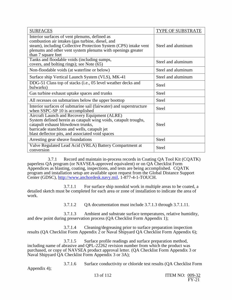
SURFACES TYPE OF SUBSTRATE
Underwater hull, including appendages and surfaces below the waterline up to and including the boottopping
All
Cofferdams Steel and aluminum
Hangar, flight, vertical replenishment, and aircraft elevator platform decks
Steel and aluminum
Recovery, Assist, Securing and Traversing (RAST) track trough (including sumps)
Steel and aluminum
Well deck overheads and enclosed boat handling areas Steel and aluminum
Surface ship bilges (including sumps) Steel and aluminum
13 of 112 ITEM NO: 009-32 FY-21
SURFACES TYPE OF SUBSTRATE
Interior surfaces of vent plenums, defined as combustion air intakes (gas turbine, diesel, and steam), including Collective Protection System (CPS) intake vent plenums and other vent system plenums with openings greater than 7 square feet
Steel and aluminum
Tanks and floodable voids (including sumps, covers, and bolting rings); see Note (65)
Steel and aluminum
Non-floodable voids (at waterline or below) Steel and aluminum
Surface ship Vertical Launch System (VLS), MK-41 Steel and aluminum
DDG-51 Class top of stacks (i.e., 05 level weather decks and bulwarks)
Steel
Gas turbine exhaust uptake spaces and trunks Steel
All recesses on submarines below the upper boottop Steel
Interior surfaces of submarine sail (fairwater) and superstructure when SSPC-SP 10 is accomplished
Steel
Aircraft Launch and Recovery Equipment (ALRE) System defined herein as catapult wing voids, catapult troughs, catapult exhaust blowdown trunks, barricade stanchions and wells, catapult jet blast deflector pits, and associated void spaces
Steel
Arresting gear sheave foundations Steel
Valve Regulated Lead Acid (VRLA) Battery Compartment at conversion
Steel
3.7.1 Record and maintain in-process records in Coating QA Tool Kit (CQATK) paperless QA program (or NAVSEA-approved equivalent) or on QA Checklist Form Appendices as blasting, coating, inspections, and tests are being accomplished. CQATK program and installation setup are available upon request from the Global Distance Support Center (GDSC), http://www.anchordesk.navy.mil, 1-877-4-1-TOUCH. 3.7.1.1 For surface ship nonskid work in multiple areas to be coated, a detailed sketch must be completed for each area or zone of installation to indicate the area of work. 3.7.1.2 QA documentation must include 3.7.1.3 through 3.7.1.11. 3.7.1.3 Ambient and substrate surface temperatures, relative humidity, and dew point during preservation process (QA Checklist Form Appendix 1); 3.7.1.4 Cleaning/degreasing prior to surface preparation inspection results (QA Checklist Form Appendix 2 or Naval Shipyard QA Checklist Form Appendix 6); 3.7.1.5 Surface profile readings and surface preparation method, including name of abrasive and QPL-22262 revision number from which the product was purchased, or copy of NAVSEA product approval letter. (QA Checklist Form Appendix 3 or Naval Shipyard QA Checklist Form Appendix 3 or 3A); 3.7.1.6 Surface conductivity or chloride test results (QA Checklist Form Appendix 4);

14 of 112 ITEM NO: 009-32 FY-21
3.7.1.7 Surface cleanliness test results for dust (QA Checklist Form Appendix 5); 3.7.1.8 Name of coating, manufacturer, batch number, and date of expiration (QA Checklist Form Appendix 6); 3.7.1.9 Elapsed time between coats (QA Checklist Form Appendix 6); 3.7.1.10 DFT measurements (QA Checklist Form Appendix 7) and/or WFT measurements (QA Checklist Form Appendix 7A or Naval Shipyard QA Checklist Form Appendix 7); 3.7.1.11 Minimum and maximum storage temperatures of the coating over the 24-hour period prior to use (QA Checklist Form Appendix 1). 3.7.2 If using QA Appendices, submit one legible copy, in hard copy or approved transferrable media, of recorded in-process information on QA Checklist Forms to the SUPERVISOR within 72 hours of completion of preservation of each separate location listed in the invoking Work Item or task order. 3.8 Determine the type of surface preparation required and coating system options that are available for use in accomplishing the work. 3.8.1 Accomplish receipt inspection for coatings applied on aircraft carriers and submarines to areas listed in 3.7 (excluding underwater hull and nonskid systems) upon receipt from the manufacturer. Accomplish testing of the following properties in accordance with the requirement of the applicable specification and the manufacturer’s certificate of compliance or conformance test data form. Receipt inspect coating components for density, fineness of grind, viscosity, and condition in container. Receipt inspect mixed coating for dry hard time, sag resistance, and color of dry film. Receipt inspection testing is not required for those characteristics that have satisfactory test data provided on the manufacturer's certificate of compliance or conformance test data forms, or another shipyard's receipt inspection test data forms that meet the applicable coating specification requirements. Submit one legible copy, in hard copy or approved transferrable media to the SUPERVISOR upon request. 3.8.1.1 On all ships for coatings applied to areas listed in 3.7, maintain on file the original manufacturer's certificate of compliance and material conformance test data in accordance with Section 11 of 2.2. Submit one legible copy, in hard copy or approved transferrable media to the SUPERVISOR upon request. 3.8.1.2 For areas listed in 3.7, if requested by the SUPERVISOR, prepare and submit one legible copy, in hard copy or approved transferrable media, of Coatings Application Product Summary (CAPS) sheet (QA Checklist Form Appendix 8). 3.9 Maintain the following certifications for accomplishing preservation operations to areas as listed in 3.7. Information for these certifications can be found at www.sspc.org and www.naceinstitute.org/Certification. 3.9.1 Coating inspectors must be certified in accordance with the NAVSEA Basic Paint Inspector (NBPI) course, NACE International Coating Inspector Program (CIP) Level 1 or higher, or SSPC Protective Coating Inspector Program (PCI) Level 2. Coating inspectors must also have a minimum of 2 years of marine coatings related work experience.
15 of 112 ITEM NO: 009-32 FY-21
3.9.2 Organizations performing blasting operations (abrasive and waterjetting) or coating application must be certified in accordance with QP 1 of 2.5 (with the exception of the Coating Application Specialist (CAS) requirement) or NAVSEA-approved equivalent. 3.9.2.1 For components that are removed from the ship and preserved, ISO 9001 may be substituted for QP 1. 3.9.3 Spray painters must be certified in accordance with SSPC C-12, SSPC C-14, SSPC CAS Level 2, or NAVSEA-approved equivalent. For equivalent certifications, a copy of the NAVSEA approval letter must be maintained by the repair activity. 3.9.4 Plural Component Pump Tenders and Applicators must be certified in accordance with SSPC C-14 or NAVSEA-approved equivalent certifications. For equivalent certifications, a copy of the NAVSEA approval letter must be maintained by the repair activity. 3.9.5 Blasters must be certified in accordance with SSPC C-7, SSPC CAS Level 2, or NAVSEA-approved equivalent. For equivalent certifications, a copy of the NAVSEA approval letter must be maintained by the repair activity. 3.9.6 Blasters performing UHP WJ must be certified in accordance with SSPC C-13 or NAVSEA-approved equivalent. For equivalent certifications, a copy of the NAVSEA approval letter must be maintained by the repair activity. 3.10 For all coating systems except surface ship nonskid, accomplish preservation operations in accordance with the following. For surface ship nonskid system application, refer to 3.11. (V) "ENVIRONMENTAL READINGS" 3.10.1 For coatings, take ambient and substrate surface temperatures, relative humidity, and dew point from conditions on-site, in close proximity to the structure being coated, for all areas listed in Tables One through 8. 3.10.1.1 Unless otherwise stated within the Notes of Tables One through 8, and as noted in 3.10.1.2, 3.10.1.3, and 3.11.2.3, coatings must be applied only when the ambient temperature and the temperature of the prepared substrate are 50 degrees Fahrenheit or greater and a minimum of 5 degrees Fahrenheit above the dew point. The maximum relative humidity must be 85 percent. For areas listed in 3.7, readings must be documented on QA checklist Form Appendix 1. 3.10.1.2 In areas where MIL-PRF-23236 Type VII Class 15B products are specified, these products are exempt from dew point and relative humidity requirements. 3.10.1.3 The only products that may be applied below 50 degrees Fahrenheit are those specified in the Tables and Notes for use below 50 degrees Fahrenheit. 3.10.1.4 These environmental readings must be taken from the surface preparation acceptance checkpoint to 48 hours of creditable cure time after the application of a coat. Creditable cure time is defined in 3.6.7. For areas preserved under 3.6.1.1/3.6.1.3, environmental readings must be taken at the surface preparation acceptance checkpoint to 24 hours after application of a coat. If a final coat fully cures to immersion/service in less than 48 hours (24 hours for 3.6.1.1/3.6.1.3), as defined in its NAVSEA-reviewed ASTM F718, environmental readings for that final coat must be taken until the product's cure to immersion/service time is reached. For potable, reserve feedwater, and freshwater drain

16 of 112 ITEM NO: 009-32 FY-21
collecting tanks on submarines and aircraft carriers, during inspection of each coat, the (G) point inspection must validate that the environmental readings during application and curing of that coat comply with applicable environmental requirements. All components blasted and primed in accordance with 3.1.4 must have environmental readings taken until the cure to recoat time is reached. 3.10.1.5 For potable, reserve feedwater, and freshwater drain collecting tanks, environmental readings must be taken from the surface preparation acceptance checkpoint to 5 days of creditable cure time after application of the final coat, unless otherwise stated in Tables One through 8. 3.10.1.6 The preferred method of measurement is use of a data logger. If a data logger is used, it must collect data at a minimum of every one hour. A manual reading must be taken once every 24 hours and at every evolution involving (G)-points with a separate calibrated device independent of the data logger. For areas listed in 3.7, manual readings must be documented on QA Checklist Form Appendix 1. Maintain all data logger recorded data for the requirements of 3.10.1 with the QA appendices. 3.10.1.7 For areas where a data logger is not used, environmental readings must be manually taken every 4 hours and at every evolution involving (G)-points except as modified below. For areas listed in 3.7, readings must be documented on QA Checklist Form Appendix 1. 3.10.1.8 For areas where relative humidity is maintained (through the use of dehumidification equipment or forced hot air) below 50 percent and the surface temperature is greater than 5 degrees above the dew point, manual readings where a data logger is not used are required once every 12 hours and at every evolution involving a (G)-point. This requirement also applies to coatings covered under 3.10.1.2. 3.10.1.9 Environmental readings at (G)-points are only required within the timeframes given in 3.10.1.4 and 3.10.1.5. 3.10.1.10 Environmental readings must be monitored during application of powder coating products, but they do not need to be recorded. (I) or (I)(G) "CLEANLINESS" (See 4.4) 3.10.2 Accomplish degreasing/cleaning prior to surface preparation to ensure that the surface is free of contaminants in accordance with SSPC-SP 1 of 2.5. For areas prepared to NACE/SSPC-SP WJ-2 of 2.5 and 2.10 with UHP WJ equipment, the requirement of initial degreasing/cleaning is waived. A visual water break test (ASTM F-21 or F-22) on the surface may be used to validate SSPC-SP 1 and NACE/SSPC-SP WJ-2 of 2.5 and 2.10. For areas listed in 3.7, document on QA Checklist Form Appendix 2 or Naval Shipyard QA Checklist Form Appendix 6. 3.10.2.1 Inspect the surface a maximum of 4 hours prior to start of coating removal to ensure accomplishment of SSPC-SP 1. For areas listed in 3.7, document on QA Checklist Form Appendix 2 or Naval Shipyard QA Checklist Form Appendix 6. 3.10.3 Except for tanks, surface preparation by abrasive blasting is prohibited on submarine interior surfaces, with the exception that use of self-contained Recyclable Encapsulated Abrasive Media material conforming to SSPC-AB 4 is permissible in submarine machinery spaces.

17 of 112 ITEM NO: 009-32 FY-21
3.10.4 Limit the square footage of surfaces being prepared for preservation to an area that can be coated prior to the occurrence of flash rusting and/or oxidation. Remove any flash rust prior to coating, except as follows: 3.10.4.1 Surfaces cleaned by waterjetting must meet the applicable NACE/SSPC Standard for flash rust. For submarines, the first coat of epoxy primer must be applied within 24 hours of coating removal if removal is by non-automated waterjetting. 3.10.4.2 The water used in waterjetting must not include detergents or inhibitors without written approval from the coating manufacturer and the SUPERVISOR. (I) or (I)(G) "SURFACE PROFILE" (See 4.4) 3.10.5 One profile measurement must be recorded for every 200 square feet for the first 1,000 square feet; for each additional 500 square feet or less, one profile measurement must be taken. Profile measurements must be taken in accordance with Method B or Method C of 2.9. For Method B of 2.9, one profile measurement must be the average (mean) of 10 individual readings. For profile measurements taken in accordance with Method C of 2.9, use profile tape suitable to read subject profile (i.e., coarse to extra-coarse plus). For Method C of 2.9, one profile measurement must be the average (mean) of 2 individual readings. If any individual reading is found to be greater than or equal to 5 mils, use Method B of 2.9 in those areas to determine existing profile. The retention of profile tape is not required. For areas listed in 3.7, document surface profile on QA Checklist Form Appendix 3 or Naval Shipyard QA Checklist Form Appendix 3 or 3A. 3.10.5.1 Following blasting or waterjetting operations, surface peak-to-valley profile must be checked. Surface profile must be validated on areas without visible pitting. For Method B of 2.9, each profile measurement must be between 2 and 4 mils. For Method C of 2.9, each profile measurement must be between 2 and 4 mils, with no individual tape reading less than one mil or greater than or equal to 5 mils. If such profile is not present, repair activity must establish the proper profile. 3.10.5.2 Following power tool cleaning to SSPC-SP 11 of 2.5, surface profile must be checked. Profile measurements must be 2 mils minimum for areas listed in 3.7 and one mil minimum for all other areas where accessible (inaccessible areas must be determined by inspection and agreed to by the SUPERVISOR). 3.10.5.3 For products without a NAVSEA-reviewed F718, manufacturer’s instructions may be substituted. 3.10.5.4 Conversely, excessive use of mechanical tools (grinders, sanders, chippers, etc.) must be minimized to avoid metal loss. Overly aggressive blasting which causes metal thickness loss over the amount required for surface profile must also be avoided. Excessive depth of profile can cause problems with poor coating performance. A greater than recommended surface profile requires a paint film be applied to totally cover the profile to prevent pinpoint or flash rust. The increase in paint film thickness also increases the susceptibility of solvent entrapment, causing blistering and premature failure of the coating. 3.10.5.5 Due to the potential for excessive metal loss, for LCS 2 Class ships and SSN-21 and SSN-774 Class submarines, only the following power tools may be used to obtain an SSPC-SP 11 surface: needle guns, bristle blasters, and rotary peening tools. On LCS 2 Class ships and submarines, any areas of potential metal loss by corrosion or mechanical means must be documented and reported to the SUPERVISOR.
18 of 112 ITEM NO: 009-32 FY-21
3.10.5.6 Recyclable Encapsulated Abrasive Media material conforming to SSPC-AB 4 may not establish a sufficient surface profile. If this method is employed and the profile is insufficient to meet the requirements, the repair activity must establish a sufficient surface profile. 3.10.5.7 Waterjetting will not establish a surface profile. If this method is selected by the repair activity and a surface profile does not exist or is insufficient to meet the requirements, the repair activity must establish a sufficient surface profile. (I)(G) "CONDUCTIVITY OR CHLORIDE MEASUREMENT" 3.10.6 For surfaces listed in 3.7 (excluding potable water and reserve feedwater tanks on submarines, and freshwater drain collecting tanks on aircraft carriers), accomplish the requirements for conductivity or chloride measurements as follows: 3.10.6.1 Following coating removal, accomplish conductivity or chloride measurements in accordance with the requirements of 3.10.6.3. 3.10.6.2 Additionally, accomplish a visual inspection within 4 hours prior to application of each coat. If evidence of contamination of the surface exists, accomplish the requirements of 3.10.6.3. 3.10.6.3 Accomplish surface conductivity or chloride checks using available field or laboratory test equipment on the freshly prepared surface. One reading must be taken for every 200 square feet for the first 1,000 square feet. One determination must be conducted for every additional 500 square feet or less. For immersed applications, such as tanks and bilges, chloride measurements must not exceed 3 µg/cm2 (30 mg/m2); conductivity measurements must not exceed 30 micro-siemens/cm. For non-immersed applications, chloride measurements must not exceed 5 µg/cm2 (50 mg/m2); conductivity measurements must not exceed 70 micro-siemens/cm. Conductivity samples must be collected using a product that meets the requirements of ANSI/NACE SP0508 of 2.10, “Methods of Validating Equivalence to ISO 8502-9 on Measurement of the Levels of Soluble Salts.” Document on QA Checklist Form Appendix 4. 3.10.6.4 Because conductivity testing measures more than just chlorides, for any conductivity check that fails, a confirmatory chloride check may be conducted to confirm chloride levels. If the chloride levels do not exceed the requirements in 3.10.6.3, the measurement passes the conductivity/chloride check. 3.10.6.5 If a conductivity check fails and the confirmatory chloride check is not conducted, or if chloride measurements exceed the respective values, water wash (3,000–5,000 PSI) the affected areas with potable water. Dry the affected areas and remove all standing water. Accomplish surface conductivity or chloride checks on affected areas in accordance with 3.10.6.3. Repeat step until satisfactory levels are obtained. 3.10.6.6 If, after a freshwater wash, the measurements exceed required levels, a salt remover may be used; however, the only salt remover products that may be used for a coating system are those specified on that coating's NAVSEA-reviewed ASTM F718. (I) or (I)(G) "SURFACE PREPARATION" (See 4.4) 3.10.7 Verify surface preparation for the coating systems specified in the Work Item or task order and Tables One through 8 are in accordance with 2.5 and 2.10. For areas listed in
19 of 112 ITEM NO: 009-32 FY-21
3.7, document on QA Checklist Form Appendix 3 or Naval Shipyard QA Checklist Form Appendix 6. 3.10.7.1 For surface ships, surface cleanliness for dust must be accomplished for the underwater hull and documented on QA Checklist Form Appendix 5. Surface cleanliness for dust must meet Rating 2, Class 2, of 2.11. One dust tape reading must be taken for every 200 square feet for the first 1,000 square feet; for each additional 500 square feet or less, one tape reading must be taken. The tape reading requirement is waived if the final stage of surface preparation for the entire surface is UHP WJ. 3.10.7.2 When waterjetting has been performed to a specified WJ level of cleanliness on a steel surface, and the level of flash rust (low, moderate, or high) cannot be agreed upon between the authorized coating inspector and the Contractor through the use of the written NACE/SSPC WJ standard or the SSPC-VIS 4 visual reference standard, the procedure in Attachment B must be used to resolve the dispute. 3.10.7.3 The checkpoints of 3.10.5, 3.10.6, and 3.10.7 can be accomplished concurrently. 3.10.8 Coating systems must be applied and cured in accordance with this NAVSEA Standard Item and applicable NAVSEA-reviewed ASTM F718s as defined in 3.1.13. 3.10.8.1 For surface ship preservation of areas not listed in Tables One through 5, see the Tables in Section 1 of 2.2. For submarine preservation of areas not listed in Tables 6 through 8, see the Tables in 2.6. 3.10.8.2 Coatings must not be thinned. 3.10.8.3 Unless fully enclosed, (i.e., with containment), do not perform exterior paint application when sustained winds exceed 15 miles per hour (MPH). (I) or (I)(G) "COATING INSPECTION FOR EACH COAT" (Consists of Coating Thickness,
Holidays, and Cleanliness) (See 4.4) 3.10.9 Inspect each Prime, Intermediate, Stripe, Tack, and Top Coat (including Capastic) as follows: 3.10.9.1 Accomplish DFT measurements of each coat applied for the coating systems listed in Tables One through 8. This excludes any stripe coats and draft marks. For areas listed in 3.7, document on QA Checklist Form Appendix 7. 3.10.9.2 Accomplish a visual holiday check on each coat of the system. For areas listed in 3.7, document on QA Checklist Form Appendix 7. Any holiday found must be identified and touched-up. These touched-up holidays do not constitute a new coat. Paint containing Optically Active Pigment (OAP) must be visually inspected using violet light. Where an OAP primer is used, each primer and topcoat must be visually checked using violet light. When this occurs, the inspector must use a violet-light flashlight conforming to ASTM E2501 to enhance the normal visual inspection process. An ASTM E2501 flashlight produces violet light that activates the fluorescent OAP. The inspector must wear yellow or amber-tinted glasses that block ultraviolet and violet light to accomplish the inspection. See ASTM E2501 for the light transmittance specification for tinted glasses and http://www.nstcenter.biz for a list of safety eyewear models that meet the specification. Guidance regarding OAP inspection practices is available in SSPC-TU 11.

20 of 112 ITEM NO: 009-32 FY-21
3.10.9.3 Accomplish a visual inspection for surface cleanliness. If evidence of contamination exists, accomplish degreasing/cleaning a maximum of 4 hours prior to application of next coat to ensure removal of surface contaminants. For areas listed in 3.7, document on QA Checklist Form Appendix 7 or 7A or Naval Shipyard QA Checklist Form Appendix 6 or 7. If condition is UNSAT, then also use Appendix 2 or Naval Shipyard QA Checklist Form Appendix 6. 3.10.9.4 Accomplish a visual inspection for chloride contamination for areas listed in 3.7 (excluding potable water and reserve feedwater tanks on submarines, and freshwater drain collecting tanks on aircraft carriers). If evidence of chloride contamination exists, accomplish requirement of 3.10.6.5 on the affected area(s) approved by the SUPERVISOR, a maximum of 4 hours prior to application of next coat to ensure removal of surface contaminants. Document on QA Checklist Form Appendix 7 or 7A or Naval Shipyard QA Checklist Form Appendix 6 or 7. If condition is UNSAT, then also use Appendix 4 as required in 3.10.6.3 to 3.10.6.5. 3.10.10 For DFT readings required in 3.10.9.1, DFT readings for each coat must be taken in accordance with Method PA 2 of 2.5. When measuring full coats to determine total system thicknesses denoted in Tables One through 8, DFT readings must not be taken in areas where stripe coatings have been applied. When scanning technology is used in SSPC-PA 2 fixed batch mode (average of three readings), the average DFT displayed in each batch will be recorded in Appendix 7. 3.10.10.1 WFT readings are required in lieu of DFT readings for any coat that must be in a tacky state (as defined in 3.6.3) when the next coat is applied, for non-metallic surfaces, for anti-corrosive and antifouling paint applied over Capastic and sprayable shields, and when applied over existing coatings. For metallic surfaces, the number of WFT spot readings must be 2 readings per 1,000 square feet. For non-metallic surfaces, the number of WFT spot readings must equal the number of DFT readings that would have been taken. When WFT readings are used in this manner, the sampling frequency, distribution, and acceptance criteria must be the same as described in SSPC-PA 2 of 2.5, except that only one WFT reading is required to represent a “spot measurement” instead of the three “gauge readings” defined in SSPC-PA 2. WFT equals DFT divided by percent solids by volume (when percent solids by volume is expressed as a decimal, i.e., 60 percent equals 0.60). For areas listed in 3.7, document on QA Checklist Form Appendix 7A or Naval Shipyard QA Checklist Form Appendix 7. 3.10.10.2 If any coat measures less than its specified DFT, apply an additional coat of that product. The total DFT of these 2 coats must not exceed the specified maximum thickness for the original coat as specified in Tables One through 8. If an additional coat is required, accomplish a cleanliness checkpoint in accordance with 3.10.9.3 prior to application of the additional coat. 3.10.10.3 During paint application, a WFT gauge must be used to verify the application of proper paint thickness for each coat of all coating systems listed in Tables One through 8. WFT readings must be taken to confirm this, but need not be recorded. 3.10.10.4 Except to remediate small, localized drips or sags totaling less than 0.03 percent of the coated area, excessive DFT must not be sanded to reduce DFT without approval of the SUPERVISOR. 3.10.10.5 MIL-PRF-23236 Type VII paints require additional DFT readings to be performed in accordance with Attachment A. These readings must be performed following the last coat of MIL-PRF-23236 Type VII paint on the areas where the stripe coat would have been applied.
21 of 112 ITEM NO: 009-32 FY-21
3.10.11 With the exception of potable water, reserve feedwater, and freshwater drain collecting tanks, when performing QA inspections for holidays and DFT readings, for all areas where aesthetics are not an issue, permanent markers, as approved by the SUPERVISOR, are acceptable. These markings may be directly overcoated with the next coat of paint (or remain exposed if used on the final coat in an area where aesthetics are not an issue). 3.11 NONSKID. Except for peel and stick nonskid, which must have preservation operations as specified in 3.10, accomplish preservation operations for surface ship nonskid systems in accordance with the following: 3.11.1 When installing nonskid systems to critical coated areas (listed in 3.7) within enclosed spaces, including exterior temporary structures for environmental control, the following conditions must be maintained for a minimum of 48 hours after application of each coat of the nonskid system: 3.11.1.1 Maintain sufficient volumetric air changes to satisfy 2.3 requirements that ventilation be provided in sufficient quantities to keep the concentration of coating solvent vapors below ten percent of their lower explosive limit. 3.11.1.2 Continuously maintain airflow into and out of the enclosed space to satisfy the requirements of 2.3. Fully open hangar doors satisfy 2.3 requirements. 3.11.1.3 Orient input air such that airflow is directed towards or across the deck and in the direction of the exhaust ventilation ports. Locate exhaust ventilation ports such that the bottom of the exhaust duct/opening is less than one foot from the deck surface to ensure that “heavier than air” coating solvent vapor is effectively removed from the enclosed space. 3.11.1.4 Evenly distribute input and exhaust ports such that uniform air movement throughout the enclosed space and across deck surface is maintained. Ensure airflow is not “short circuited” from input to exhaust by maximizing distance between input and exhaust ports. 3.11.1.5 Ensure the ventilation system remains operational and powered throughout application of the nonskid system regardless of whether personnel are in the enclosed space. (V) "ENVIRONMENTAL READINGS" 3.11.2 Accomplish the requirements of 3.10.1 (environmental) with the following additions: 3.11.2.1 Record ambient and substrate surface temperatures, relative humidity, and dew point readings at one-hour intervals during nonskid system application. 3.11.2.2 Unless fully enclosed (i.e., with a tent), do not apply nonskid primer when sustained winds exceed 15 MPH. 3.11.2.3 Unless the applicable NAVSEA-reviewed ASTM F718 is more stringent, ambient air temperature must be 55-100 degrees Fahrenheit, deck temperature for primer application must be 40-120 degrees Fahrenheit, and deck temperature for nonskid application must be 40-110 degrees Fahrenheit. Deck temperature must be a minimum of 5 degrees Fahrenheit above the dew point for nonskid system application. For application of Type

22 of 112 ITEM NO: 009-32 FY-21
VIII (low temperature) nonskid systems, ambient air and deck temperatures must be between 35 degrees Fahrenheit and the upper limit specified by the NAVSEA-reviewed ASTM F718. 3.11.3 Accomplish the requirements of 3.10.2 through 3.10.4 with the following additions: 3.11.3.1 If cleaning is performed via solvent wiping, after solvent wiping, the deck must be allowed to dry before application of any coating. No visible solvent must be present on deck surfaces prior to proceeding with the next process step. Solvent wiping is defined in 3.6.5. 3.11.3.2 When a solvent wipe is performed, annotate Appendix 2 or Naval Shipyard QA Checklist Form Appendix 6 with type of solvent and time allowed to dry. 3.11.3.3 When cleaning exterior nonskid decks with High Pressure Water Cleaning (HP WC), cleanliness must meet the requirements of SSPC-SP WJ-4/NACE WJ-4 instead of SSPC-SP 1. 3.11.3.4 For tie-downs prepared to SSPC-SP 2, 3, or 15 of 2.5, the initial SSPC-SP 1 is waived if the final stage of surface preparation is UHP WJ in accordance with NACE/SSPC-SP WJ-2 of 2.5 and 2.10. (I) or (I)(G) “SURFACE PROFILE” (See 4.4) 3.11.4 Following blasting or waterjetting operations, surface peak-to-valley profile
must be checked. Surface profile must be validated on areas without visible pitting. For each
area of preparation, one profile measurement must be taken every 100 square feet for the first
500 square feet. Only one profile measurement must be taken for every 1,000 square feet
remaining. Profile measurements must be taken in accordance with Method B or Method C of
2.9; For Method B of 2.9, one profile measurement must be the average (mean) of 10 individual
readings. For Method B of 2.9, each profile measurement must be between 3 and 6 mils. For
profile measurements taken in accordance with Method C of 2.9, use profile tape suitable to read
subject profile (i.e., coarse to extra-coarse plus). For Method C of 2.9, one profile measurement
must be the average (mean) of 2 individual tapes. For Method C of 2.9, each profile
measurement must be between 3 and 6 mils, with no individual tape reading less than 2.5 mils or
greater than, or equal to 5 mils. If any individual tape reading is found to be greater than, or
equal to, 5 mils, use Method B of 2.9 in those areas to determine existing profile. If such profile
is not present on decks and aircraft elevators, repair activity must establish proper profile. The
maximum profile requirement is waived for carrier aircraft elevators prepared via waterjetting.
The maximum profile requirement is 7 mils on aluminum aircraft elevators and CG-47 class
flight decks when prepared by abrasive blasting. The retention of profile tape is not required. For
areas listed in 3.7, document on QA Checklist Form Appendix 3 or Naval Shipyard QA
Checklist Form Appendix 3 or 3A.
3.11.4.1 For nonskid areas that abrasive blast equipment or waterjet equipment cannot access, substrate must be prepared to SSPC-SP 11, except that minimum profile must be 2 mils where accessible. Underside of tie-downs must be prepared to SSPC-SP 2 or SSPC-SP 3 of 2.5; however, feathering requirements of 3.6.4 are waived, while remainder of tie-down must be prepared to SSPC-SP 15 of 2.5.

23 of 112 ITEM NO: 009-32 FY-21
3.11.4.2 The requirements of 3.10.5.4 through 3.10.5.6 apply to nonskid systems. 3.11.5 Accomplish the requirements of 3.10.6 for conductivity/ chloride measurements with one reading to be taken for every 200 square feet for the first 1,000 square feet and one reading for every additional 1,000 square feet or less. 3.11.6 Accomplish the requirements of 3.10.7 for surface preparation. 3.11.6.1 Surface cleanliness for dust must be accomplished for nonskid flight decks and documented on QA Checklist Form Appendix 5. Surface cleanliness for dust must meet Rating 2, Class 2, of 2.11. Three individual readings must be taken every 100 square feet for the first 500 square feet. If the tape readings are consistent, only one tape reading must be taken for every 1,000 square feet remaining. The tape reading requirement is waived if the final stage of surface preparation for the entire surface is UHP WJ and the primer is applied within 6 hours of completion of surface preparation. 3.11.6.2 For flight deck areas, not to include aircraft elevator platform decks, receiving a nonskid system and prepared to NACE/SSPC-SP WJ-2, a minimum of 20 percent of the total area receiving a nonskid system must be abrasively blasted to an NACE 2/SSPC-SP 10 level of cleanliness. The areas to be prepared to NACE 2/SSPC-SP 10 must be as directed by the SUPERVISOR. 3.11.7 Nonskid systems must be applied in accordance with the applicable Tables. A new nonskid system must overlap existing nonskid system to the minimum extent necessary to create a continuous film as agreed upon by the SUPERVISOR. 3.11.7.1 Nonskid must be rolled parallel to ship's main axis. Welds parallel with the direction of peaks and valleys must be cross-rolled. Cross-rolling must extend 3 to 6 inches on each side of the weld. The requirement to roll nonskid parallel to the ship's main axis is waived on LCS 2 class flight decks and any other areas with extruded aluminum plank decks as approved by the SUPERVISOR. In these areas, nonskid must be rolled perpendicular to the ship's main axis. 3.11.7.2 Nonskid material remaining in the can after nonskid is poured onto primed deck surface must not be removed from the can. 3.11.7.3 If probing the nonskid surface with a dull putty knife results in penetration of the putty knife into the nonskid, neither foot nor vehicular traffic must be permitted. 3.11.7.4 DFT measurements of nonskid primer in overlap areas must be no more than 15 mils. 3.11.8 Accomplish the requirements of 3.2 for stripe coat with the exception that stripe coat may precede prime coat. 3.11.8.1 For overcoating of stripe coat or stripe coating of the primer coat, refer to the applicable NAVSEA-reviewed ASTM F718. When the stripe coat is applied prior to overcoating with a full coat of primer, the stripe coat must be dry to touch in accordance with ASTM D1640.

24 of 112 ITEM NO: 009-32 FY-21
3.11.8.2 A second full coat of proprietary nonskid primer listed on the QPL for MIL-PRF-24667 may be applied if approved by the SUPERVISOR. The second full coat satisfies the stripe coat requirement. 3.11.9 Nonskid application must begin within 36 hours of completion of final full primer coat application. For areas not listed in 3.7, nonskid overcoating application must be in accordance with NAVSEA-reviewed ASTM F718. For areas listed in 3.7, use the following: 3.11.9.1 If nonskid application begins within 36 to 72 hours after completion of final full primer coat application, the primer coat must be solvent wiped with solvent required by the NAVSEA-reviewed ASTM F718. 3.11.9.2 If nonskid application begins within 3 to 7 days after completion of final full primer coat application, the primer coat must be solvent wiped with solvent required by the NAVSEA-reviewed ASTM F718, then lightly abraded, solvent wiped again, and a mist coat (one to 2 mils) of primer must be applied and allowed to cure to recoat. 3.11.9.3 If the primer coat is not overcoated with nonskid within 7 days of final full primer coat application, the primer must be removed and the surface preparation repeated. For zone tie-in areas where the primer is to be overcoated with itself (up to 12 inches of overlap), the recoat window must be in accordance with the NAVSEA-reviewed ASTM F718; the primer must be solvent wiped with solvent required by the NAVSEA-reviewed ASTM F718, then lightly abraded, then solvent wiped again. 3.11.9.4 Aircraft carrier landing areas not overcoated with nonskid within 72 hours of primer application completion must have surface preparation repeated. 3.11.10 Accomplish the requirements of 3.10.9 through 3.10.11 for inspection of nonskid primer (full and stripe coats). (I) or (I) (G) "NONSKID MIXING AND APPLICATION" (See 4.4) 3.11.11 Accomplish the following requirements during initiation of the mixing and application process: 3.11.11.1 Verify that nonskid mixing blade is free of previously cured coatings. 3.11.11.2 Verify that applicator meets NAVSEA-reviewed ASTM F718 mixing and application requirements, including: specified mixing equipment, pre-mix time, mix time, induction time, pot-life and any product specific application requirements. (I) or (I) (G) “NONSKID SPREAD RATE AND HOLIDAY INSPECTION” (See 4.4) 3.11.12 Verify that nonskid spread rate meets the following requirement: Types I, V, VI, VII, and VIII - 18 square feet/gallon minimum and 30 square feet/gallon maximum; Types II, III, IX and X - 23 square feet/gallon minimum and 35 square feet/gallon maximum; and, Types IV and IX (sprayed) - 60 square feet/gallon maximum. Perform visual holiday inspection of nonskid and document on QA Checklist Form Appendix 7. Spread rate must be determined by the following formula: [(square feet coated) / ((gallons per kit) x (number of kits))]. 3.11.12.1 Holidays less than 4 square inches must be touched-up as follows: 1) solvent clean primer with solvent required in product NAVSEA-reviewed ASTM F718, 2) lightly sand exposed primer, 3) solvent clean sanded surface with solvent required in product

25 of 112 ITEM NO: 009-32 FY-21
NAVSEA-reviewed ASTM F718, and 4) apply nonskid to primer to approximate texture of surrounding nonskid. Overcoat window restrictions do not apply to touch-up of holidays in non-landing areas. Holidays less than 1/8 of a square inch must be exempt from touch-up. 3.11.13 Inspect the location and color of required VLA markings in accordance with Naval Air Warfare Center Aircraft Division (NAWCAD) Class Guidance Drawings, Air Capable Ship Aviation Facilities Bulletin, Amphibious Assault Ship Aviation Facilities Bulletin, Shipboard Aviation Resume (NAEC-ENG-7576), VLA General Service Bulletin No. 8 (latest revision) or by contacting the local NAWC (CAFSU/ASIR) Field Office. 3.12 For submarines, accomplish preservation of damping and acoustic tiles and surfaces in way of these tiles in accordance with the following. All exterior tiles and tiles inside tanks must be installed over a surface prepared to NACE 2/SSPC-SP 10 and painted with the preservation system indicated in Table 8. Surfaces beneath exterior tiles and tiles inside tanks are considered critically coated. Care must be taken to ensure blasting does not damage tiles. Surface preparation and preservation of steel restrained tiles must be as listed in Table 8. Paint only steel portions of SSBN/SSGN-726 Class acoustic baffles. Before overcoating tile that is currently coated, sweep blast the surface to roughen the existing paint. Non-steel restraining covers are not required to be painted except for antifouling purposes. Overspray of otherwise unpainted covers is acceptable. Full paint out of non-steel damping restraining covers, unrestrained damping, and acoustic tile (including Gradual Transition Coating) and covers is not intended. In interior spaces, exposed surfaces of acoustical absorptive treatments that are painted must be prepared to SSPC-SP 1 and must be painted with 1-2 mils of paint (avoid filling perforations) to match surroundings. 4. NOTES: 4.1 Wet space decks include sanitary spaces (washrooms, water closets, and showers), food service spaces (galley, scullery, butcher shop, bakery, meat prep rooms, and food service line), and trash compactor rooms. 4.2 Total DFT encountered during removal may exceed specified Table thicknesses. 4.3 Total removal of ablative coating is not required. An ablative copper antifoulant (AF) coating system must not be removed by blasting prior to its specified service life unless it is blistered, peeling, or otherwise damaged beyond repair. Stable and intact ablative AF coatings must be retained and overcoated. The total film thickness of the combined retained and freshly applied paint must comply with Table One/Table 6. When the Work Item or task order calls for overcoating of retained intact ablative copper AF coating, AF surfaces must be washed down with fresh water. For all ships except submarines and aircraft carriers, this fresh water washdown must be performed at 2,000 PSI as the vessel comes out of the water, in order to prevent slime and oxidized paint from drying on the hull and inhibiting leaching of the paint when the ship is returned to the water. For submarines and aircraft carriers, instead, within 24 hours of the hull being released by cognizant shipyard authorities, pressure wash with fresh water between 2,000 and 5,000 PSI. The surface must be cleaned and dried before new paint is applied. Apply any anti-corrosive (AC) paint to areas in need of repairs. Overcoat the AC paint with the approved AF paint of the same MIL-PRF-24647 Type. The Work Item or task order will specify the degree of removal. 4.4 The paragraphs referencing this note are considered an (I)(G) if the inspection/test is on a critical surface as listed in 3.7. If the inspection/test is not on a surface listed in 3.7, then the paragraph is considered an (I).

26 of 112 ITEM NO: 009-32 FY-21
4.5 Refer to 009-03 of 2.1 as appropriate for requirements concerning potential exposure to toxic or hazardous substances and hazardous operations. 4.6 The repair activity may use environmental enclosures to control environmental conditions. 4.7 Preservation system repairs are an Unrestricted Operations (URO) Maintenance Requirement Cards (MRC) program attribute. 4.7.1 The Unrestricted Operations (URO) Maintenance Requirement Cards (MRC) program was developed by NAVSEA to monitor specific areas of interest to determine if the conditions of these areas are suitable for continued unrestricted operations. Maintaining the protective capability of the coating system is critical to maintaining structural integrity during the periods between inspections. For this reason, complying with requirements for coating system application for all aspects of the preservation process is essential. Other systems that impact the URO MRC program are Special Hull Treatment (SHT) application process, including Mold-In-Place (MIP), maintenance of cathodic protection systems (Impressed Current Cathodic Protection (ICCP) and anodes) and installation of various types of tiles (acoustic, damping, etc.). 4.7.1.1 Substrate preparation and preservation are not authorized/covered in this Standard Item for vertical launch system (VLS) bathtub area, thin line towed array (TLTA) interior, surfaces covered by SHT, propulsor, and retractable bow plane recesses on submarines. 4.7.2 Preservation work in submarine tanks and enclosed spaces is usually scheduled to occur when the tanks and spaces are opened and entered to perform URO MRC structural inspections. Any time a tank or other enclosed space is entered, if a URO MRC 003 structural inspection is not authorized, an inspector qualified in accordance with URO MRC 003 will perform a structural visual examination. 4.7.3 Any URO MRC item being blasted and painted will have a URO MRC hull survey inspection performed by an inspector qualified in accordance with URO MRC 003 prior to blasting and again prior to repainting. 4.8 Painting of rubber piece parts of pipe hangers is permitted in the following areas: Main Ballast Tanks (MBTs), freeflood areas, and internal tanks which are normally painted. The rubber piece parts include the liners, grommets, and inserts found in steel strap and steel block type pipe hangers; also included is the block rubber type pipe hangers. Prior to painting rubber piece parts in surface ship potable water and reserve feedwater tanks, existing paint must be removed to an SSPC-SP 2 level of cleanliness as approved by the SUPERVISOR. Do not paint rubber piece parts in surface ship FWDCTs, submarine RFTs, and hangers on nuclear piping that traverses other non-nuclear tanks. 4.9 Inspections such as URO inspections and inspection periodicities are addressed in 2.2 and 2.6. 4.10 For peel and stick nonskid, interior and exterior applications on surface ships in 3.1.26; Category II Standard Item 009-26 “Deck Covering Requirements; accomplish”, including Attachment G will be specified in the work item. 4.11 Unless otherwise noted, aircraft carriers are considered surface ships throughout this document. The tables are split up between surface ships and submarines. Table One is for surface ship underwater hull areas. Table 2 is for surface ship exterior areas. Table 3 is for surface ship interior spaces. Table 4 is for surface ship tanks and voids. Table 5 is for surface

27 of 112 ITEM NO: 009-32 FY-21
ship miscellaneous areas. Table 6 is for submarine exterior hull areas. Table 7 is for submarine interior areas. Table 8 is for submarine tanks and voids. 4.12 The repair activity must not coat reactor plant items cited in the ship’s reactor plant paint schedule in accordance with this Standard Item.

28 of 112 ITEM NO: 009-32 FY-21
Attachment A Edge DFT Measurement In addition to the required DFTs per SSPC-PA 2, a separate set of “edge” DFT readings must be taken in close proximity to corners and edges of area structural elements including, but not limited to stiffeners, “rat holes,” cut-outs, and frames. This data must be taken in accordance with SSPC-PA 2 and reported separately from those required by 3.10.9.1, with the following modifications: 1) The “edge” gauge readings must be taken approximately ¼ inch (i.e., 0.5 cm) from edges using micro-probe gauges with a probe less than or equal to ½-inch in diameter. For “edge” readings taken on substrates less than ½ inch thick, readings must be taken from the “middle” of the substrate. Microprobe gauges must be calibrated, in accordance with manufacturer’s direction, to measure paint thicknesses expected during application. 2) Welds not associated with corners or edges (i.e., a butt weld joining 2 flat plates) must be inspected using standard visual techniques. The inherent roughness of the weld precludes the collection of reproducible data from these areas. Inspectors may, if they choose, take a spot reading within ¼ inch (i.e., 0.5 cm) from a butt weld. 3) An "edge" spot measurement must consist of 3 gauge readings taken within a 1.5 inch (i.e., 4 cm) diameter circle. Accomplish front, back, and edge DFT gauge readings as shown in Figure A-1 (see attached). For each data set required for the flat surface data set the equivalent is required for the edge or corner data set. For example, if 20 spot DFT measurements are required for an area, then 20 DFT measurements are required using the front, back, edge method set and 20 for the flat surface set.
Figure A-1

29 of 112 ITEM NO: 009-32 FY-21
Attachment B NAVSEA Flash Rust Adjudication Procedure: When waterjetting has been performed to a specified WJ level of cleanliness on a steel surface, and the level of flash rust (low, moderate, or high) cannot be agreed upon between the authorized coating inspector and the Contractor through the use of the written NACE/SSPC WJ standard or the SSPC-VIS 4 visual reference standard, the following procedure must be used to resolve the dispute. Note that this procedure is not a substitute for the definitions contained in the NACE/SSPC standard, but rather is intended to provide objective quality evidence (OQE) that a disputed zone, surface, or area has a low, moderate or high level of flash rust. 1. Ensure Surface Condition. The zone, surface, or area must have been cleaned to the required waterjetting level of cleanliness in accordance with 2.5 and 2.10 and possess a level of flash rust that cannot be readily gauged or appraised with certitude using the guidelines of 2.5, 2.10, and SSPC-VIS 4 alone. 2. Determine Minimum Number of Samples. One flash rust reading (consisting of one test measurement and one control measurement) must be taken for every 200 square feet for the first 1,000 square feet of a zone, surface, or area. For each additional 500 square feet or increment thereof, one additional flash rust reading must be taken.
CAUTION Excessive pressure applied to the tape can crack the slide and create a dangerous, sharp surface.
3. Prepare Test Sample and Control Sample. Both the test and control samples are prepared by applying a 4-5 inch long piece of ISO 8502-3 dust tape to a 1.2 mm thick clean, clear microscope slide which is 50mm by 75mm or larger. The tapes for the test and control samples must be prepared as described in the sub-paragraphs below. Fully adhere the adhesive side of the tape to the slide, centering the tape’s length over the 75mm dimension of the glass. To help secure the tape to the slide, not more than 1/4 inch of the tape end may be wrapped under the slide. Additional tape may interfere with the measuring devices. Any sample with air bubbles larger than 1/4 inch in diameter must be rejected. Using a permanent marker to write on a non-test portion of the slide, date and uniquely identify each sample. 3.1 Test Sample Tape Preparation. For each test sample, the dust tape is applied to a representative area of the flash rusted surface before being applied to the microscope slide. The inspector must rub the tape onto the flash rusted surface with his/her thumb or other finger, pressing as hard as possible over the central 3 inches of the tape without damaging it. Remove the tape from the steel in a manner that retains as much of the adherent rust as possible; do not shake the tape or try to dislodge the rust.
30 of 112 ITEM NO: 009-32 FY-21
Attachment B (Con’t)
3.2 Control Sample Tape Preparation. While avoiding transferring fingerprints to the central 3 inches of tape, apply a control piece of tape from the same roll as that used for the test sample to a separate clean, clear microscope slide. 4. Measure Transmittance. For each test and control tape/microscope-slide assembly, measure the transmittance using a Laser Labs Model LM100, Monroe PMP Model PD2.1, Monroe PMP Model PD3.0, or NAVSEA-approved equivalent transmittance measurement meter. Transmittance measurements must not be made in direct sunlight or in an area where the ambient light level exceeds 100 foot candles. Insert the slide into the instrument with the tape facing the meter's light source. Record two measurements from different locations on the test sample. Record 2 measurements from the control tape, taking one measurement from each end. Subtract the average of the 2 test readings from the average of the two control readings. The difference in average transmittance of the test sample (i.e., sample with flash rust) and the average transmittance of the control sample must constitute one transmittance reading. 5. Adjudicate Flash Rust Level. A difference in transmittance reading (i.e., control minus test sample) must be applied to the entire zone, surface, or area which the measurement is intended to represent. The percentage difference between the average control and test sample values, as compared to the control sample, must be used to establish the following flash rust levels:
WJ "High" level of flash rust: greater than 20 percent difference in transmittance readings. WJ “Moderate” level of flash rust: 10 percent to 20 percent difference in transmittance readings. WJ “Low” level of flash rust: less than 10 percent difference in transmittance readings.
If the adjudicated flash rust level is determined to be greater than the requirements for the area allow, then the area must be re-cleaned until the specification is met. 6. Retain Samples. All test transmittance samples and control transmittance samples must be retained as objective quality evidence that the required level of surface cleanliness was obtained.

31 of 112 ITEM NO: 009-32 FY-21
Attachment C Process for Spot and Sweep Blast of the Underwater Hull and Freeboard 1. The “Spot and Sweep” method must only be used if authorized by the SUPERVISOR prior to the start of work in these areas. The use of this Spot and Sweep process must only apply to the underwater hull and freeboard areas of the ship and may only be considered for use on surface ships. 2. The spot and sweep blast process must be performed by a robotic crawler unit that uses UHP WJ. For areas not accessible by the robotic crawlers, UHP lances and/or abrasive blasting may be used to create either a NACE/SSPC-SP WJ-4/M surface or an SSPC-SP 7 surface, respectively. SSPC-SP 3 power tool cleaning may be used for feathering in the spot and sweep-prepared surfaces. 3. Examine the existing coating on the ship’s hull and determine the color sequence of the current epoxy coating system prior to blasting. The anticipated sequence is red epoxy primer followed by gray epoxy tie coat. The examiner must note these colors for use during inspection of the hull prior to application of the first coat of epoxy primer. 4. The UHP robotic crawler unit must be set up to accomplish the following:
(a) Remove all loose and degraded coating, rust and fouling from areas of bare metal to create a NACE/SSPC-SP WJ-2/M surface. (b) For the underwater hull: Remove all antifouling coating and remove approximately 1/2 of the thickness of the current MIL-PRF-24647 epoxy tie coat from the underwater hull area. (c) For the freeboard portion of the hull: Remove all of the MIL-PRF-24635 coating, regardless of thickness, and remove approximately 1/2 of the thickness of the top MIL-PRF-24647 or MIL-PRF-23236 epoxy coat from the freeboard area. (d) Smoothly feather or transition from areas of bare metal to the retained epoxy coating. Areas of sharp or "step" transition between bare metal and paint must be noted on the applicable QA appendix form in the comments section. Also, feather edges as needed where the UHP robotic crawler leaves behind markings in the existing paint (concentric circles).
5. The use of the Spot and Sweep method does not waive any surface preparation QA steps. Conduct all QA inspections on bare metal areas and record QA data. Areas of retained paint must be visually inspected and must satisfy the following:
(a) There must be no more than two colors of paint visible in any area of retained coating. Inspectors must observe the red primer adjacent to any bare metal areas and then continue observations into the bulk of the retained epoxy. Gray epoxy may be retained on top of the red primer, but any visual evidence of additional coats of red or black paint (indicating antifouling coating retention) or haze gray MIL-PRF-24635 (indicating silicon alkyd/polysiloxane coating retention) on top of the gray epoxy must be cause for closer inspection. Closer inspection must be conducted from a minimum distance of 3 feet. Upon closer inspection, a solvent-wipe test with a white rag must be conducted using an antifouling coating clean-up solvent. If the solvent wipe test shows color transfer onto the

32 of 112 ITEM NO: 009-32 FY-21
rag, the area must be rejected. Rejected areas must be cleaned again until no color transfers to the rag. (b) Minimize areas of sharp transition or steps between bare metal and paint. Any such areas must be inspected and tested with a dull putty knife to determine adhesion. If the paint flakes or can be dislodged, the area must be rejected and cleaned again to remove the loose paint. (c) Feather the transition areas where partial blasted areas occur next to bare steel blasted areas. Sharp edges must be removed in accordance with SSPC-SP 3 and the areas feathered for a smooth transition.
6. The first step of the coating application process must be as follows: Apply one coat of epoxy primer in accordance with Tables One and 2 to all areas in the zone or work area (i.e., both bare metal and retained epoxy primer) to achieve the specified epoxy coating thickness. Do not apply a thin or varied primer thickness when traversing areas between bare metal and retained epoxy.
7. Coating inspections must be performed for each coat of paint in accordance with 3.10.9. In bare metal areas, DFT readings must be measured and recorded. In areas of retained paint, however, WFT readings must be measured and recorded in place of DFT readings for determining proper coating thickness for each coat. (Follow the requirement for taking WFT readings in place of DFT readings for accept/reject criteria). In areas of retained paint, DFT readings must still be measured and recorded. However, high DFT readings must not be cause for rejection; such readings must only be measured for documentation purposes. 8. Once the primer has reached the cure to overcoat state, the surface area must be inspected for edge lifting of the remaining epoxy that was overcoated. This inspection must be conducted at a maximum distance of 15 feet. As it cures, the epoxy primer may lift any loose edges of the existing coating that may not have been visible during the initial surface preparation inspection. Any areas where the paint has lifted must be prepared in accordance with SSPC-SP 3 and primed. This inspection may be included as part of the DFT/WFT and visual holiday inspection. 9. For underwater hull areas:
(a) Apply second / tie coat of epoxy and first coat of antifouling in accordance with Table One. (b) Apply remaining antifouling system in accordance with Table One.
10. For freeboard areas, apply second coat of epoxy then the topcoat in accordance with applicable Line in Table 2.

33 of 112 ITEM NO: 009-32 FY-21
Attachment D
ICCP Sprayable Dielectric Shields Application Instructions For Removed/New Anode
Installation
1.Prior to surface preparation, remove existing anode. If new installation, install gland body and
anode mounting studs.
2.Install plug or masking material for the protection of areas not to be painted.
3.Prepare surface in accordance with requirements listed in the Table and Line for “Dielectric
Shields” and QA checkpoints are conducted in accordance with 3.7.
a. For 8 foot anode, prepare area 15 feet by 22 feet in accordance with Figure D-1.
b. For 4 foot anode, prepare area 15 feet by 18 feet in accordance with Figure D-1.
c. For 2 foot anode, prepare area 15 feet by 16 feet in accordance with Figure D-1.
NOTE: All coatings must be listed in the Table and Line for “Dielectric Shields” and be applied
in accordance with their NAVSEA-reviewed ASTM F718. All QA checkpoints must be
conducted in accordance with 3.7.
4.Apply primer to the DFT required by the manufacturer’s NAVSEA-reviewed ASTM F718.
NOTE: Intermediate and topcoat cannot be applied at required thickness in single pass without
significant runs and sags. To prevent application defects, apply coatings in two passes as
instructed below.
5.Within the primer’s specified overcoat window, apply the first pass of the intermediate coat at
a thickness between 13 and 18 mils. The intermediate coat must be applied to the anode area
within 5 to 7 inches of the primer boundary, leaving a 5 to 7 inch band of primer along the
perimeter.
a. For 8 foot anode, coat area 14 feet by 21 feet in accordance with Figure D-1.
b. For 4 foot anode, coat area 14 feet by 17 feet in accordance with Figure D-1.
c. For 2 foot anode, coat area 14 feet by 15 feet in accordance with Figure D-1.
6.Within 5 minutes of completion of the first pass, begin applying the second pass of
intermediate coat to acquire the required minimum DFT of 30 mils.
7.Within the intermediate coat’s specified overcoat window, apply the first pass of topcoat coat
at a thickness between 13 and 18 mils in a contrasting color. The topcoat must be applied to the
anode area within 5 to 7 inches of the intermediate coat boundary, leaving a 5 to 7 inch band of
intermediate coat along the 5 to 7 inch band of primer.
a. For 8 foot anode, coat area 13 feet by 20 feet in accordance with Figure D-1.
b. For 4 foot anode, coat area 13 feet by 16 feet in accordance with Figure D-1.
c. For 2 foot anode, coat area 13 feet by 14 feet in accordance with Figure D-1.

34 of 112 ITEM NO: 009-32 FY-21
8.Within 5 minutes of completion of the first pass, begin applying the second pass of topcoat to
acquire the required minimum DFT of 30 mils.
9.Allow topcoat to cure for minimum recoat time and ensure the total coating system meets the
required 70 mils minimum DFT and does not exceed 100 mils within the footprint of the anode.
10. Remove plugs and masking material from step 2.
11. Apply a 1/8 inch bead of MIL-A-46106 room-temperature volcanizing (RTV) silicone
adhesive-sealant to neoprene mat around each stud holes leaving 1/2 inch clearance from the
edge of the hole and around the edge of the entire mat, again leaving 1/2 inch clearance from the
edge.
12. Place neoprene mat on hull (RTV silicone adhesive-sealant side towards the hull),
leaving equal clearance around all studs and the gland socket.
13. Insert anode into the socket.
14. While holding the anode in place, apply RTV silicone adhesive-sealant around each stud
up to the bottom of the counterbore.
15. Install the nuts handtight, then from the center out, torque the nuts to between 8 and 10
foot-pounds.
16. Apply RTV silicone adhesive-sealant up to the top of the counterbore and insert anode
cap. Allow the RTV silicone adhesive-sealant to cure to service.
17. Protect the face of the anode, ensuring all of the platinum surfaces are covered to prevent
damage.
18. Within the topcoat’s specified overcoat window, apply the underwater hull coating
system over the entire dielectric shield area.
19. Remove masking from step 17.
Note: If any overcoat windows are breached, standard recovery methods apply – hand sand with
80 grit sandpaper to degloss, then solvent wipe to SSPC-SP 1 cleanliness and continue painting.

35 of 112 ITEM NO: 009-32 FY-21
22 ft (8ft anode)
18 ft (4ft anode)
15 ft
16 ft (2ft anode)
14 ft 13 ft
21 ft (8ft anode)
17 ft (4ft anode)
15 ft (2ft anode)
20 ft (8ft anode)
16 ft (4ft anode)
14 ft (2ft anode)
Figure D-1: Area to abrasive blast
DS or Standard
Anode
- Neoprene Mat
- UHS Topcoat
- UHS Intermediate Coat
- UHS Primer
- U/W Hull Coating System (AC/AF)
RTV/Anode Cap
Figure D-2: Cross section of coating system and anode

36 of 112 ITEM NO: 009-32 FY-21
Attachment E
ICCP Sprayable Dielectric Shields Application Instructions Without Removal of Existing
Anodes
1. If anode is determined to be in good condition, install a fitted metal covering to prevent
damage during surface preparation and coating application.
2.Low pressure water wash the existing Capastic shield.
3.Abrasive blast the shield area to SSPC-SP 5, leaving a 10 inch diameter ring of Capastic
around the anode. Feather the transition between bare steel and the anode, gradually tapering the
Capastic from the height of the anode to the bare steel in one smooth transition. QA checkpoints
are conducted in accordance with 3.7.
4.Inspect remaining Capastic to ensure it is tightly adherent, intact, and has no visible cracking.
If the Capastic is in good condition, move to step 6.
5.If any unsound Capastic is found within the 10 inch ring, blast the area to SSPC-SP 5 and
apply Capastic. If for any reason the Capastic is not able to be repaired, or damage to the anode
is found, the anode must be removed and the shield preserved in accordance with Standard Item
009-32.
6.Hand sand the remaining Capastic with 80 grit sandpaper and solvent wipe to SSPC-SP 1
cleanliness.
NOTE: All coatings must be listed in the Table and Line for “Dielectric Shields” and be applied
in accordance with their NAVSEA-reviewed ASTM F718. All QA checkpoints must be
conducted in accordance with 3.7.
7.Apply primer to the DFT required by the manufacturer’s NAVSEA-reviewed ASTM F718.
a. For 8 foot anode, prepare area 15 feet by 22 feet in accordance with Figure E-1.
b. For 4 foot anode, prepare area 15 feet by 18 feet in accordance with Figure E-1.
c. For 2 foot anode, prepare area 15 feet by 16 feet in accordance with Figure E-1.
NOTE: Intermediate and topcoat cannot be applied at required thickness in single pass without
significant runs and sags. To prevent application defects, apply coatings in two passes as
instructed below.
8.Within the primer’s specified overcoat window, apply the first pass of the intermediate coat at
a thickness between 13 and 18 mils. The intermediate coat must be applied to the anode area
within 5 to 7 inches of the primer boundary, leaving a 5 to 7 inch band of primer along the
perimeter.
a. For 8 foot anode, coat area 14 feet by 21 feet in accordance with Figure E-1.

37 of 112 ITEM NO: 009-32 FY-21
b. For 4 foot anode, coat area 14 feet by 17 feet in accordance with Figure E-1.
c. For 2 foot anode, coat area 14 feet by 15 feet in accordance with Figure E-1.
9.Within 5 minutes of completion of the first pass, begin applying the second pass of
intermediate coat to acquire the required minimum DFT of 30 mils.
10. Within the intermediate coat’s specified overcoat window, apply the first pass of topcoat
coat at a thickness between 13 and 18 mils in a contrasting color. The topcoat must be applied to
the anode area within 5 to 7 inches of the intermediate coat boundary, leaving a 5 to 7 inch band
of intermediate coat along the 5 to 7 inch band of primer.
a. For 8 foot anode, coat area 13 feet by 20 feet in accordance with Figure E-1.
b. For 4 foot anode, coat area 13 feet by 16 feet in accordance with Figure E-1.
c. For 2 foot anode, coat area 13 feet by 14 feet in accordance with Figure E-1.
11. Within 5 minutes of completion of the first pass, begin applying the second pass of
topcoat to acquire the required minimum DFT of 30 mils.
12. Allow topcoat to cure for minimum recoat time and ensure the total coating system meets
the required 70 mils minimum DFT.
13. Within the topcoat’s specified overcoat window, apply the underwater hull coating
system over the entire dielectric shield area.
14. Remove masking from step 1.
Note: If any overcoat windows are breached, standard recovery methods apply – hand sand with
80 grit sandpaper to degloss, then solvent wipe to SSPC-SP 1 cleanliness and continue painting.

38 of 112 ITEM NO: 009-32 FY-21
22 ft (8ft anode)
18 ft (4ft anode)
15 ft
16 ft (2ft anode)
14 ft 13 ft
21 ft (8ft anode)
17 ft (4ft anode)
15 ft (2ft anode)
20 ft (8ft anode)
16 ft (4ft anode)
14 ft (2ft anode)
Figure E-1: Area to abrasive blast
Standard Anode
- Capastic
- UHS Primer
- UHS Intermediate Coat
- UHS Topcoat
- U/W Hull Coating System (AC/AF)
Figure E-2: Cross section of coating system and anode

40 of 112 ITEM NO: 009-32 FY-21
NOTES OF TABLES ONE THROUGH 5 FOR SURFACE SHIPS (1) Draft marks are applied directly over the complete antifouling system. (2) Boottop - The boottopping is defined as the black area from minimum load waterline at
which the ship is expected to operate to 12 inches above the maximum load waterline. The black paint is an antifouling paint conforming to MIL-PRF-24647. The haze gray MIL-PRF-24635 must not overlap onto the black MIL-PRF-24647 antifouling topcoat.
(3) This area includes DDG-51 Class top of stacks (i.e., 05 level weather decks and
bulwarks). (4) For the structural decks within the machinery spaces above the bilge line, use the Table
Lines for “INTERIOR DECK PASSAGEWAYS NOT RECEIVING DECK COVERINGS.”
(5) Applicable to mast and yardarm surfaces as approved by the SUPERVISOR. (6) A minimum of 24 hours drying time must be allowed after last coat prior to undocking. (7) Within a zone or work area, a proprietary nonskid system listed on the QPL for
MIL-PRF-24667 must be used. (8) For applications below 50 degrees Fahrenheit, MIL-PRF-24647 coatings must be used in
accordance with the NAVSEA-reviewed ASTM F-718 to determine lower application temperature limit. Do not apply these coatings below 35 degrees Fahrenheit.
(9) MIL-PRF-24596, Grade C, Classes 1 and 2 or MIL-DTL-24607 must be used if surface
and ambient temperatures are less than 50 degrees Fahrenheit. (10) The "inner shield" is defined as the portion of the dielectric shield that extends 3 ft. from
the anode in all directions. The "outer shield" is defined as the portion of the dielectric shield from the inner shield to a distance of 6 ft. from the anode. Repair of the inner shield area is required when total deteriorated inner shield surface area is from 0 to 2 percent, and no single spot is greater than one square foot. Repair of the outer shield area is required when total deteriorated outer shield surface area is from 0 to 10 percent, and no single spot is greater than one square foot. Replacement (new installation) of the entire dielectric shield is required when either of the above criteria is exceeded (damage to the inner shield is greater than 2 percent, OR damage to the outer shield is greater than 10 percent, OR any single spot damage is greater than one square foot). Repair of this system must be performed with EVOQUA Water Technologies LLC part number Capastic™ 35524 (W3T106410).
(11) Attachments D must be used for sprayable dielectric shield application for removed and
new anode installations. Attachment E must be used for sprayable dielectric shield application without removal of existing anodes.
a. During visual inspection, ensure anode surfaces are undamaged and free of paint and
dielectric shield material. b. The anode should remain covered with heavy cardboard or plywood to prevent
damage or contamination by the ship’s underwater hull coating system until just before undocking.

41 of 112 ITEM NO: 009-32 FY-21
(12) These systems may also be invoked for preservation of decks in spaces that are prone to wear and do not receive deck covering.
(13) Anchors below lower boottopping limit must be painted in accordance with normal
underwater hull anti-corrosion/antifouling system. (14) For MCM class ships, use walnut shells, garnet, or crushed glass for abrasive blast media.
Waterjetting to NACE/SSPC-SP WJ-2/L may be used in place of NACE 2/SSPC-SP 10. Waterjetting to NACE/SSPC-SP WJ-3/L may be used in place of NACE 3/SSPC-SP 6.
(15) Anchor chain and detachable links must be marked and color-coded in accordance with
NSTM Chapter 581 unless otherwise directed by the Work Item or task order. Stern gate chain must be haze gray.
(16) Apply polysulfide compound conforming to MIL-PRF-81733, Type II, Class 2, after
primer application, prior to topcoat application. (17) Colors shown in Tables 631-8-10 and 631-8-11 of 2.2 must be specified by TYCOM or
ship's Commanding Officer in accordance with Paragraph 631-8.18.3.2 of 2.2. (18) Restore each compartment marking in accordance with 2.12 and 2.13. (19) MIL-PRF-24667 nonskid systems must be applied as a complete system from the same
manufacturer. The use of any manufacturer’s MIL-PRF-24667 color topping is authorized over any MIL-PRF-24667 nonskid including type XI nonskid.
(20) Prior to accomplishing painting of wooden underwater hulls, allow the hull to dry to a
moisture content of 15 percent. Readings must be taken with an electronic moisture meter, Sovereign Moisture Master or equal. Cover grounding plates and zincs prior to painting.
(21) Blasted surface metal must be degreased following walnut shell blasting. Even traces of
residual oil will degrade paint adhesion. Appropriate safety precautions for working with flammable solvents must be enforced. Alternate procedure is a vigorous soap and water wash followed by pressurized fresh water rinse. Do not use a detergent and fresh water washdown when using aluminum oxide as an abrasive blast medium.
(22) Peripheral deck edging and areas not receiving nonskid may use either the manufacturer's
MIL-PRF-24667 color topping or MIL-PRF-24635 Type V. Aircraft tie-downs may be coated with MIL-DTL-24441 F-155 in lieu of nonskid color topping.
(23) For DDG Flight II class ships where troughs are installed, topcoat using Deck Gray for
trough covers and troughs. (24) This product must be spray applied where possible. All references to “brush coat” or
“brush application” may be accomplished using a paint brush or a paint roller or cartridge unit. Multiple coats applied by brush/roller/cartridge unit must be substituted for one coat of the spray application of 20-30 mils total in areas where plural-component spray application is not feasible or for paint touch-up. For brush application, the spray version of each product may be brush-applied or the brush coat version of the product may be used.
For application of the "single coat" products (by brush, roller, or spray), the product must
be applied all at one time, meaning during a continuous spray and touch-up operation.

42 of 112 ITEM NO: 009-32 FY-21
Specifically, a “single-coat” system involves one color of paint, applied during one work evolution (i.e., no time is required to wait for the paint to dry), with a single pass or double pass. Because the spray application is one work evolution, coating inspection QA checkpoint 3.10.9 need only be conducted after completion of application of the full coat. Completing a single work evolution may involve actions over numerous days, but it is still one evolution, requiring one QA checkpoint. If a tank or void is touched-up with a contrasting color, it is acceptable for the area to have a multi-color appearance.
(25) Power impact tool cleaning using power-driven needle guns, chipping or scaling
hammers, rotary scalers, single or multiple-piston scalers, or other similar impact cleaning tools must not be utilized in the cleaning methods.
(26) For coating repair or replacement, maintain the relative humidity in the tank or void
space at a maximum of 50 percent from surface preparation checkpoint acceptance until cure to recoat time of final touch-up of the topcoat; relative humidity must be maintained at a maximum of 85 percent from cure to recoat for the final touch-up of the topcoat through cure to service. For in-service coating touch-up until cure to immersion of topcoat, maintain relative humidity at a maximum of 85 percent.
(27) Finish coats for boats and craft must be as specified in Paragraph 631-9.3.2 through 631-
9.3.3 of 2.2 unless otherwise specified in the invoking Work Item or task order. (28) Thermal insulation must be soap and water cleaned and hand sanded. (29) Three coats of MIL-DTL-24441, Type III at 3-4 mils per coat can be substituted for 2
coats of MIL-DTL-24441, Type IV at 4-6 mils per coat, for total system DFT of 8-12 mils. Three full coats and 2 stripe coats of MIL-DTL-24441, Type III at 3-4 mils per coat can be substituted for 2 full coats and one stripe coat of MIL-DTL-24441, Type IV at 4-6 mils per coat, for total system DFT of 8-12 mils.
(30) Grit blasting to near white metal is the preferred method of surface preparation. Only
where grit blasting is not possible should power tool cleaning be used with prior authorization by the SUPERVISOR. Power tool cleaning should not be used for well deck areas frequently exposed to LCAC exhaust.
(31) A low-pressure (3,000 to 5,000 PSI) fresh water washdown of the well deck area must be
performed before either grit blasting or power tool cleaning to remove dirt, oil, grease, salts, and loosely adherent paint.
(32) Upon completion of the 3.10.7 surface preparation, pH measurements will be
documented on QA Checklist Form Appendix 3 in the comments section or Naval Shipyard General Comment Sheet. The pH must be in the range of 6.5 to 7.5. If the pH is not within this range, wash the surface with potable water until the required pH is obtained.
(33) If approved by the SUPERVISOR, the surface preparation method of Spot and Sweep,
described in Attachment C may be used in place of the surface preparation SSPC/NACE standard required in the Table Line.
(34) These systems may also be invoked for preservation of well deck bulkheads and decks. (35) Topcoat jet blast deflector (JBD) pits and barricade stanchions with one coat MIL-DTL-
24441 or MIL-PRF-23236 Type VI, white, at 2-4 mils.

43 of 112 ITEM NO: 009-32 FY-21
(36) SSPC-SP 11 must be the surface preparation standard used, even if the applicable NAVSEA-reviewed ASTM F718 has a more stringent requirement.
(37) Total DFT specified for potable water tanks must not be exceeded except in isolated areas
adjacent to shapes and stiffeners. In no case must the maximum DFT be exceeded by 2 mils. The isolated areas must be less than 2 percent of the total area.
(38) Maintain the relative humidity in the tank at a maximum of 85 percent from the start of
abrasive blasting to cure of the topcoat. By allowing 85 percent vice 50 percent relative humidity, this will reduce the service life of the tank from 15-20 years to 10-12 years.
(39) PPG Industries PSX 892HS must not be used for surfaces that exceed 700 degrees
Fahrenheit. (40) Do not stripe coat inside surfaces of the Sonar Trunk Guide Rail angles. (41) Apply 3 coats of a vapor barrier-coating compound, MIL-PRF-19565, in contrasting
colors (final coat white), to thermal insulation within laundries, sculleries, galleys, drying rooms, and to thermal insulation on the warm side of refrigerated stores spaces.
(42) High temperature areas of exhaust pipe exteriors include BLISS caps, air eductors, and
exhaust stacks. (43) In lieu of white, use Light Gray, Color No. 26373 (Low Solar Absorption only). In lieu
of black, use Ocean Gray, Color No. 26173 (Low Solar Absorption only). (44) These systems must also be invoked for Aircraft Electrical Servicing Stations (AESS)
trunks. (45) Passive Counter-measure System (PCMS) tile on the bow flares must be painted with the
same topcoat as the freeboard. (46) For heavily pitted areas, substitute Sherwin-Williams Fast Clad primer or International
THA787/785 for the prime coat; apply at 4-8 mils. Then apply the topcoat at 16-22 mils if spray applying or 2 coats at 8-11 mils each if applied by brush/roller/cartridge unit. The primer application constitutes a separate QA checkpoint from the topcoat; however, the checkpoint for the primer must be (I) instead of (I) (G).
(47) The topcoats for ordnance/non-ordnance pyrotechnic locker sun shields must be painted
white or as directed by NAVSEA. (48) All of the AC and AF coats in the product system must be from the same manufacturer. (49) For touch-up of Sherwin-Williams Fast Clad ER, Fast Clad Brush Grade may be used.
Fast Clad Brush Grade is applied at 8-10 mils/coat. For touch up of Interline 783, Interline 624 can be used. Interline 624 is applied at 4-8 mils/coat.
(50) "Cosmetic" color topping is not to be applied on top of nonskid on vertical replenishment
or aviation decks. (51) Inorganic zinc silicate coatings must be applied in accordance with the manufacturer’s
instruction.

44 of 112 ITEM NO: 009-32 FY-21
(52) Do not blast fin stabilizers to near white metal. As-received fin stabilizers must be brush-off blasted to NACE 4/SSPC-SP 7 (Brush-Off Blast Cleaning) in lieu of near white metal blast to ensure polymer fairing compound is not removed prior to application of paint. Blank, wrap, cover, or mask equipment, shafts and openings to preclude damage and prevent entry of contaminants prior to cleaning operation. Remove protective covering upon completion of preservation operations.
(53) “Total System” value is only listed when it is more stringent than the sum of the
individual coats of the system. (54) This Table Line does not apply to propulsion plant water tanks aboard nuclear-powered
ships. (55) For MIL-PRF-23236 Type VII Class 9, 9/18, 11, and 11/18 paints, follow the NAVSEA-
reviewed ASTM F718 for temperatures, cure and recoat times. This supersedes the 70 degree Fahrenheit, 36/12-hour/5 day requirement.
(56) Do not apply nonskid to 7 inch wide strip of deck surface in way of the hangar door seal
interface on DDG-51 Class Flight II-A ships. (57) Painting PCMS tile on paint-allowed PCMS ships will be to match surrounding surfaces
and as designated by the SUPERVISOR. Painting is prohibited on no-paint PCMS ships. (58) Products used for the primer or single coat must contain OAP. Touch-up coating is not
required to contain OAP. (59) Composition L nonskid may be used in Composition G areas with TYCOM approval. (60) MIL-PRF-24667 Composition L material must be applied in areas designated by the
VLA General Services Bulletin Number 8. (61) For flight decks equipped with RAST tracks, see Figure One for guidance on RAST track
plates.

45 of 112 ITEM NO: 009-32 FY-21
Figure One
NOTES: 1. APPLY NONSKID ONLY TO CROSS-HATCHED AREAS. 2. NO NONSKID ON 2-3/4 to 3-1/4 INCH DIAMETER CIRCLES CENTERED ON HOLES. (62) Once the old nonskid system is removed, or if it is a new deck being prepared for nonskid
system installation, the surface of the GRP fiberglass must be lightly hand-sanded with 80-grit paper to roughen the surface.
(63) Nonskid must be applied to within 2-3 inches of deck fittings and protrusions. Nonskid
must be applied to within 4-6 inches from coamings and deck edges. Areas underneath protrusions, such as stowage racks or fire stations that are normally found on hangar
½ INCH
½ INCH 4 ½ INCH
SEE NOTE 2
SEE NOTE 1
RAST TRACK
4 ½ INCH
½ INCH
½ INCH
½ INCH
SEE NOTE 2

46 of 112 ITEM NO: 009-32 FY-21
decks, or coaming areas of decks not subject to vehicle or aircraft movement, need not comply with the 4-6 inch rule for applying nonskid near deck edges.
(64) Primer coat(s) must be from the same manufacturer as the other coats in the system. (65) Fuel oil storage, fuel oil service, and diesel service tanks are not required to be painted
unless specifically addressed in the tables. For existing paints, when flaking occurs, SSPC-SP 3 surface preparation must be accomplished and a light coat of system fluid must be wiped over the surface prior to closing. If preconstruction primer was applied in accordance with 3.1.5, it may be retained, but it must be overcoated with one coat MIL-PRF-23236, Type V, VI, or VII Class 5 at 4-8 mils.
(66) Do not apply primer to bulkheads and overheads. (67) Intentionally left blank. (68) For interior surfaces of stern tubes and extensions, strut barrels, fairwater interiors, shaft
flanges (not exposed to seawater) and coupling covers, do not apply antifouling topcoat. (69) Intentionally left blank. (70) MIL-PRF-24635, Type III, Class 2, Grade B or C is permitted for touch-up repairs of
existing MIL-PRF-24635, Type III, Class 2, Grade B or C. (71) Hand sand or use orbital sander with 80-120 grit sandpaper. (72) MIL-PRF-24667 Type I spray-applied products are not authorized for application to
critical coated areas on CVNs. (73) Runs, drips, and sags may appear in application of MIL-PRF-23236, Type VII paint.
When wet, runs, drips, and sags must be brushed out to form a smooth, uniform film. When cured, runs, drips, and sags must be evaluated by the SUPERVISOR and if found to be detrimental to the coating system, must be repaired.
(74) Painting over PCMS tile is not allowed, except tiles that are installed to the hull. (75) The entire deck surface (i.e. forecastle, fantail, flight, etc.) containing a Vertical
Replenishment Deck area must be considered a critical coated area as addressed in 3.7. (76) For aircraft carriers, substitute 1 stripe coat of primer for the 2nd primer full coat. (77) Bilge drain wells are to be coated with the coating systems for machinery spaces, bilges
& distilling unit pans. The coating system for AFFF decks (i.e., under AFFF Proportioning Units) may be applied to bilge drain wells.
(78) SSPC-SP 3 of tightly adherent paint may be used for locations located 12 inches and
above the inner bottom tank top for the bilge area, with the exception that the exterior structure of stand-alone tanks on aircraft carriers will require a minimum of SSPC-SP 11.
(79) These areas must be considered heavily pitted. (80) Maximum water pressure must be such that 30 seconds of stationary operation of the
vacuum self-contained equipment produces no visible degradation of the nonskid surface.

47 of 112 ITEM NO: 009-32 FY-21
Vacuum self-contained equipment must be capable of cleaning within 4 inches of bulkheads, coamings, and other deck appurtenances.
(81) Abrade sides of dielectric shield anode bars by hand with 80 grit sandpaper to SSPC-SP 2
and verify SSPC-SP 1 cleanliness prior to first application of dielectric shield to the bar. (82) Each cell hatch lip must be prepared to SSPC-SP 2. (83) Intentionally left blank. (84) Use only when substrate temperature cannot be maintained above 50 degrees Fahrenheit. (85) For DDG 1000 class ships, use one coat light gray MIL-PRF-24635 Type V or VI, Class
2, Grade B or C, 5-8 mils. (86) For aircraft carriers only, MIL-PRF-24635, Type III, Class 2, Grade B or C may be
substituted where MIL-PRF-24635, Type V and VI, Class 2, Grade B or C is specified. (87) Coat the prepared surface one foot beyond the prepared surfaces, cut back areas of 1 1/2
inches from cutouts, exposed edges, high wear areas, and label plates and 2 inches from the deck with MIL-PRF-24635, Type V of VI, Class 2, Grade B or C.
(88) If no products are listed on QPL-32584, utilize the legacy QPLs as listed below,
a. MIL-PRF-32584, Type I: MIL-PRF-32171, Type I b. MIL-PRF-32584, Type II: MIL-PRF-32171, Type III c. MIL-PRF-32584, Type III: MIL-PRF-32171, Type IV
(89) When abrasive blasting aluminum surfaces to SSPC-SP 10/NACE No. 2 Near-White
Blast Cleaning, the surface cleanliness requirements must be the same as that stated in the
standard, except that the words “corrosion products” must be substituted for the word
“rust”.
(90) When hand tool or power tool aluminum cleaning to SSPC-SP 2 Hand Tool Cleaning,
SSPC-SP 3 Power Tool Cleaning, SSPC-SP 11 Bare Metal Power Tool Cleaning, and
SSPC-SP 15 Commercial Power Tool Cleaning only stainless steel needles, stainless steel
bristle impact belts, stainless steel wire brushes, stainless steel scouring pads, or
aluminum oxide abrasive sanding pads must be used. None of these materials must have
been previously used on other metal, or for the removal of copper pigmented paint, prior
to being used on aluminum. Rotary sanders or grinders fitted with abrasive discs or flap
wheels, and rotary impact tools fitted with cutter or hammer bundle assemblies are not
authorized on aluminum substrates. Rotary impact tools may only be fitted with tungsten
carbide tipped, rubber impregnated woven nylon cloth flaps.
(91) When waterjetting an aluminum surface to SSPC-SP WJ-2/NACE WJ-2, the surface
cleanliness requirements must be the same as that stated in the standard, except that the words “corrosion products” must be substituted for the word “rust”; and the flash rusting requirement does not apply.

48 of 112 ITEM NO: 009-32 FY-21
(92) For nonskid removal using waterjetting on LCS 2 Class ships, the pressure must not exceed 30,000 PSI.
(93) After nonskid installation, remove masking from bolted-crossbar aircraft securing
fittings. Unless directed by the SUPERVISOR, do not conduct surface preparation or apply coatings to bolted-crossbar aircraft securing fittings.

49 of 112 ITEM NO: 009-32 FY-21
NOTES OF TABLES 6 THROUGH 8 FOR SUBMARINES (1A) Hull inserts must be coated with the preservation system applied to adjacent surfaces.
Extend paint system a minimum 1/2 inch on to non-ferrous liner or cladding. For MBT vent valves, preserve weld radius of the clad sealing surface and the vertical surface mating with the MBT vent valve gasket retainer; the only surface which is not painted is the horizontal clad sealing surface which mates with the MBT vent valve disc gasket.
(2A) Alternating AF colors may be used. Final coat can be red or black. (3A) The upper boottop limit is extended to 12” above the maximum condition diving trim
waterline. For all surfaces above max beam that are to receive AF, all coats must be black. The final coat of all exterior paint systems above the upper boottop must also be black.
(4A) A minimum of 24 hours drying time must be allowed after last coat prior to undocking. (5A) Products used for the primer or single coat must contain OAP. Touch-up coating is not
required to contain OAP. (6A) Blasting is not allowed in machinery spaces. (7A) Topcoat color must match surrounding paint on visible surfaces. (8A) MIL-PRF-23236 Type VII Class 17 NAVSEA-reviewed paints for interior submarine use
under the Submarine Atmosphere Control Manual are International Interbond 998 and Sherwin-Williams Euronavy ES301.
(9A) To minimize premature yellowing, chlorinated alkyd-based paints (MIL-DTL-24607)
must not be applied within 4 weeks before and after the application of amine-cured epoxy paints formulated to MIL-PRF-23236.
(10A) When using paints qualified to MIL-DTL-24607, use Table 631-8-10 of 2.2 to select
approved colors. (11A) MIL-PRF-24596 Class 2, Grade A, and Formula 25A may be substituted for MIL-DTL-
24607 chlorinated alkyd enamels. Color must match the existing surroundings. (12A) The SSBN/SSGN-726 Class logistics escape trunk (LET) fasteners and bubble skirt knife
edge in way of gaskets and fasteners for LET upper hatch fairings are to be left unpainted.
(13A) The Environmental Protection Agency (EPA) has found that samples of vermiculite ore
contain asbestos fibers. Vermiculite was used as an anti-sweat treatment on the upper hatch covers on submarines. All facilities and workers must assume vermiculite contains asbestos fibers until it has been tested. All facilities are to test new vermiculite or vermiculite in use prior to working with the material. Workers who are doing work with or near vermiculite should be aware that it may contain asbestos and proper precautions must be used.
(14A) The requirements of SSPC-SP 1 must be met via a HP or UHP fresh water washdown of
the tank prior to blasting the tank to NACE 2/SSPC-SP 10.

50 of 112 ITEM NO: 009-32 FY-21
(15A) Motor generators require protection from paints conforming to MIL-DTL-24441 or MIL-PRF-23236 during application and curing of the paint. When these paints are being applied or cured while venting in a space containing motor generators, the motor generators must be protected using a NAVSEA-approved procedure. For 300 kilo-watt (kW) and 500 kW motor generators, a positive pressure unit according to Appendix A of the motor generator technical manual must be used. Maintenance on motor generators must not be performed for a minimum of 5 days after painting with MIL-DTL-24441 and MIL-PRF-23236 paints or any application of silicones (e.g., TT-P-28, MIL-PRF-24635 silicone enamels) in the engine room.
(16A) When lead is removed from lead bins, the structure must be blasted to NACE 2/SSPC-SP
10 and preserved with an ultra-high solids paint, (even if the surrounding structure is being touch-up painted) prior to installing lead.
(17A) Immersed non-ferrous and corrosion-resistant steel piping and cable pans must be
completely coated with the specified tank or bilge paint system with the following exceptions: non-ferrous and corrosion-resistant steel piping and CRES torpedo system components in torpedo impulse tanks must not be painted; non-ferrous and CRES piping above residual waterline in MBTs is not required to be painted; in all tanks, closed system piping one inch diameter and less is to be protected from blast and is not required to be painted.
(18A) Succeeding coats of the coating system must be of contrasting color, and the top coat
must be white or a very light pastel shade. (19A) CRES fasteners (studs, nuts, washers) used to secure Type II vibration damping and
acoustic tiles may be left unpainted. (20A) Unpainted upper portions of Normal Fuel Oil (NFO) and all areas of hydraulic oil,
hydrophone, and Clean Fuel Oil (CFO) tanks must not be painted unless required in Table 8. Surface preparation and URO MRC 003 inspections are to be performed as required and bare steel must be coated with applicable system fluid or preservative as approved by the SUPERVISOR. Lube oil sludge tanks on SSBN/SSGN-726 Class submarines must not be painted.
(21A) Reduced touch-up paint curing procedures of Section 7 of 2.2 do not apply to these
surfaces. Also, note accelerated touch-up times authorized by 2.2 are for non-reactor potable water tanks only, and therefore are not to be used for potable water, reserve feedwater, and freshwater drain collecting tanks unless specifically approved by NAVSEA.
(22A) Total DFT specified in Table 8 for potable water tanks must not be exceeded except in
isolated areas adjacent to shapes and stiffeners. In no case must the maximum DFT be exceeded by more than 2 mils. The isolated areas must be less than 2 percent of the total area. For touch-up or overcoating intact aged paint in good condition, the same requirements for each coat apply, and the total film thickness maximum requirement may be corrected to allow for thickness of underlying aged paint.
(23A) Prior to surface preparation, flasks must be depressurized. Barrier protection must be in
accordance with NAVSEA S0400-AD-URM-010/TUM, Tag-Out User’s Manual (TUM), Appendix G.
(24A) Welds and area above welds will be coated with MIL-DTL-24441 primer (at 4-6
mils/coat) and 2 coats MIL-PRF-24635 (at 5 - 8 mils/coat). Tek-Haz paint system must

51 of 112 ITEM NO: 009-32 FY-21
be applied in accordance with EB Specification 4277 and will extend to a line even with the underside of the ventilation plenum welds, but not including the welds.
(25A) Bilge and Drain Collection Tanks includes the following: Bilge Collecting Tanks, Bilge
Collecting Sump Tanks, Non-Oily Drain Collecting Tanks (other than Fresh Water), Oily Drain Collecting Tanks, Bilge Water Processing Tank, Drain Water Collecting Tanks, VLS Drain Collecting Tank, Oil Collection Tanks.
(26A) For Moored Training Ships (MTS), the antifoulant coating is not required, because the
tanks are blanked off and filled with fresh water. (27A) Conduct low voltage holiday detection on 100 percent of potable water tanks when MIL-
DTL-24441 Type III paint is being applied. Holiday detection must also be performed on any repaired (touch-up) areas of an existing paint system. The holiday checks are to be performed after application of the topcoat using a low voltage wet sponge holiday detector. Any holidays (defects to bare metal) found must be marked by the inspector and the area touched-up. Holiday checks must be performed again on these areas after repair.
(28A) All painting with organic solvent-based paints (alkyd, epoxy, oil based) that exceeds 1
quart per day for the entire ship must be completed 5 days prior to the date of departure as determined by the Commanding Officer. Date of departure, as it relates to painting, is the date of first dive after departure for a period of operation.
(29A) For coating repair or replacement, maintain the relative humidity in the tank or void
space at a maximum of 50 percent from surface preparation checkpoint acceptance until cure to recoat time of final touch-up of the topcoat; relative humidity must be maintained at a maximum of 85 percent from cure to recoat for the final touch-up of the topcoat through cure to service. For in-service coating touch-up until cure to immersion of topcoat, maintain relative humidity at a maximum of 85 percent.
(30A) If no products are listed on QPL-32584, utilize the legacy QPLs as listed below, a. MIL-PRF-32584, Type I: MIL-PRF-32171, Type I b. MIL-PRF-32584, Type II: MIL-PRF-32171, Type III (31A) Tank manhole covers are critical coated areas. Solvent-based paint systems may be used
to paint manhole covers of tanks painted with high solids paint systems due to fit-up issues associated with high solids paint systems. Powder coatings must not be applied to reserve feedwater, potable water, freshwater drain collecting, and steam surge tank manhole covers.
(32A) Areas visible from above must be topcoated either gray or black. (33A) Total number of coats and total DFT specified in Table 7 for all interior spaces must not
be exceeded. Maximum system total DFT must not exceed 17 mils for surfaces topcoated with MIL-DTL-24607, 21 mils for surfaces topcoated with MIL-PRF-24596, or 24 mils for surfaces topcoated with Formula 25A.
(34A) Naval Shipyards are allowed to work on these items. All other activities are to be
approved by NAVSEA. (35A) The David Taylor Research Center paint system (DTRC 2844-1110 and 2844-1109) may
be used on other exterior hull areas. This is to allow areas adjacent to areas covered by
52 of 112 ITEM NO: 009-32 FY-21
MIP or SHT to be re-preserved the same as MIP or SHT areas. For areas requiring stripe coat, refer to 3.2.
(36A) Areas within the HOSUB Deep Submergence System/Scope of Certification (DSS-SOC)
boundary are not covered by this Standard Item but are covered by the applicable DSS-SOC preservation maintenance standard. The SUPERVISOR should be contacted to specify the areas that are outside the DSS-SOC boundary.
(37A) Runs, drips, and sags may appear in application of MIL-PRF-23236, Type VII paint.
When wet, runs, drips, and sags must be brushed out to form a smooth, uniform film. When cured, runs, drips, and sags must be evaluated by the SUPERVISOR and if found to be detrimental to the coating system, must be repaired.
(38A) Final grooming of bow domes and chin arrays must be performed by qualified shipyard
personnel. Final surface finish of bow domes must be 180 microinches Ra or smoother. Measure and record surface roughness in accordance with ASME B46.1-2009 Surface Texture (Surface Roughness, Waviness, and Lay.) If necessary, groom the surface of the dome to attain a maximum surface roughness of 180 microinches Ra. This additional grooming can be accomplished by wet sanding the surface by hand using 120 grit paper and fresh water. Refer to the appropriate bow dome manual for the class for more specific guidance on surface roughness, grooming and paint application.
(39A) For MIL-PRF-23236, Type VII, Class 9 and 9/18 paints, follow the NAVSEA-reviewed
ASTM F718 for temperatures, cure, and recoat times. This supersedes the 70 degree Fahrenheit, 36/12-hour/5-day requirement.
(40A) This product must be spray applied where possible. All references to “brush coat” or
“brush application” may be accomplished using a paint brush or a paint roller or cartridge unit. Multiple coats applied by brush/roller/cartridge unit must be substituted for one coat of the spray application of 20-30 mils total in areas where plural-component spray application is not feasible or for paint touch-up. For brush application, the spray version of each product may be brush-applied or the brush coat version of the product may be used.
For application of the "single coat" products (by brush, roller, or spray), the product must
be applied all at one time, meaning during a continuous spray and touch-up operation. Specifically, a “single-coat” system involves one color of paint, applied during one work evolution (i.e., no time is required to wait for the paint to dry), with a single pass or double pass. Because the spray application is one work evolution, coating inspection QA checkpoint 3.10.9 need only be conducted after completion of application of the full coat. Completing a single work evolution may involve actions over numerous days, but it is still one evolution, requiring one QA checkpoint. If a tank or void is touched-up with a contrasting color, it is acceptable for the area to have a multi-color appearance.
(41A) Powder coatings approved for use on submarines are listed in 2.6. (42A) Low Pressure Water Clean (LP WC) with a fan spray starting at a pressure of 1,000 PSI.
Keep the cleaning lance nozzle tip perpendicular to and at least 4” from the surface. Increase pressure, if needed, in increments of 500 PSI up to a maximum of 5,000 PSI. Remove all paints down to sound gray or green anti-corrosive paint (F-151 or F-150) or bare GRP. Remove any remaining barnacle particles or other foreign objects with wood or plastic scrapers, or by sanding. Do not use wire brushes or other abrasive instruments.

53 of 112 ITEM NO: 009-32 FY-21
(43A) Remove all marine growth and existing paint from the boot surface by LP WC or sanding with soft back dual action or soft back random orbital sanders and 60 grit paper. Observe extreme caution when LP WC. Measure stand-off distance and control nozzle pressure to assure that the boot is not damaged during the cleaning process. LP WC must be performed using fresh water with a starting pressure of 1000 PSI. Pressure must be increased in 500 PSI increments until the desired results are obtained. Scuff the entire boot surface using 60 grit paper or equivalent coarseness Scotch-Brite pad to remove any remaining paint and provide an adequately prepared surface for paint application. Clean the bare boot surface with PF-145HP degreaser (NSN 6850-01-378-0044) or degreasing solvent per MIL-PRF-680, Type I.
(44A) Do not apply nonskid to Fairwater Planes or Retractable Bow Planes. (45A) MIL-PRF-24647 coatings may be used for cold weather applications below 50 degrees
Fahrenheit. For cold weather applications of MIL-PRF-24647 coatings, the NAVSEA-reviewed ASTM F718 must be used to determine lower application temperature limit. Do not apply these coatings below 35 degrees Fahrenheit.
(46A) Navy Formula F-187 cannot be applied over F-184. (47A) If performing touch-up of paint in Steam Plant Surge Tanks, one coat Dampney
Company ENDCOR 450 (no DFT required) must be applied prior to application of the coats of Apexior No. 1.
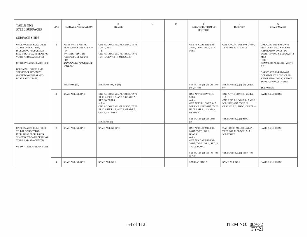
54 of 112 ITEM NO: 009-32 FY-21
TABLE ONE
STEEL SURFACES
SURFACE SHIPS
LINE
A
SURFACE PREPARATION
B
PRIMER
C
D
E
KEEL TO BOTTOM OF
BOOTTOP
F
BOOTTOP
G
DRAFT MARKS
UNDERWATER HULL (KEEL
TO TOP OF BOOTTOP,
INCLUDING PROPULSION
SHAFT OUTBOARD BEARING
VOIDS AND SEA CHESTS)
UP TO 3 YEARS SERVICE LIFE
FOR SMALL BOATS AND
SERVICE CRAFT ONLY
(INCLUDING EMBARKED
BOATS AND CRAFT)
1
NEAR WHITE METAL
BLAST, NACE 2/SSPC-SP 10
- OR -
WATERJETTING TO
NACE/SSPC-SP WJ-2/M
- OR -
SSPC-SP 10/M (WAB)/NACE
WAB-2/M
SEE NOTE (33)
ONE AC COAT MIL-PRF-24647, TYPE
I OR II, RED
-- & --
ONE AC COAT MIL-PRF-24647, TYPE
I OR II, GRAY, 5 - 7 MILS/COAT
SEE NOTES (8) & (48)
ONE AF COAT MIL-PRF-
24647, TYPE I OR II, 5 - 7
MILS
SEE NOTES (2), (6), (8), (27),
(48), & (68)
ONE AF COAT MIL-PRF-24647,
TYPE I OR II, 5 - 7 MILS
SEE NOTES (2), (6), (8), (27) &
(48)
ONE COAT MIL-PRF-24635
LIGHT GRAY (LOW SOLAR
ABSORPTION ONLY) TO
BOOTTOPPING & BELOW, 5 - 8
MILS
--OR--
COMMERCIAL GRADE WHITE
AF
ONE COAT MIL-PRF-24635
OCEAN GRAY (LOW SOLAR
ABSORPTION ONLY) ABOVE
BOOTTOPPING, 5 - 8 MILS
SEE NOTE (1)
2
SAME AS LINE ONE
ONE AC COAT MIL-PRF-24647, TYPE
III, CLASSES 1, 2, AND 3, GRADE A,
RED, 5 - 7 MILS
-- & --
ONE AC COAT MIL-PRF-24647, TYPE
III, CLASSES 1, 2, AND 3, GRADE A,
GRAY, 5 - 7 MILS
SEE NOTE (8)
ONE AF TIE COAT 3 - 5
MILS
-- & --
ONE AF FULL COAT 5 - 7
MILS MIL-PRF-24647, TYPE
III, CLASSES 1, 2, AND 3,
GRADE A
SEE NOTES (2), (6), (8) &
(68)
ONE AF TIE COAT 3 - 5 MILS
-- & --
ONE AF FULL COAT 5 - 7 MILS
MIL-PRF-24647, TYPE III,
CLASSES 1, 2, AND 3, GRADE A
SEE NOTES (2), (6), & (8)
SAME AS LINE ONE
UNDERWATER HULL (KEEL
TO TOP OF BOOTTOP,
INCLUDING PROPULSION
SHAFT OUTBOARD BEARING
VOIDS AND SEA CHESTS)
UP TO 7 YEARS SERVICE LIFE
3
SAME AS LINE ONE
SAME AS LINE ONE
ONE AF COAT MIL-PRF-
24647, TYPE I OR II,
BLACK
-- & --
ONE AF COAT MIL-PRF-
24647, TYPE I OR II, RED, 5
- 7 MILS/COAT
SEE NOTES (2), (6), (8), (48)
& (68)
2 AF COATS MIL-PRF-24647,
TYPE I OR II, BLACK, 5 - 7
MILS/COAT
SEE NOTES (2), (6), (8) & (48)
SAME AS LINE ONE
4
SAME AS LINE ONE
SAME AS LINE 2
SAME AS LINE 2
SAME AS LINE 2
SAME AS LINE ONE

55 of 112 ITEM NO: 009-32 FY-21
TABLE ONE
STEEL SURFACES
SURFACE SHIPS
LINE
A
SURFACE PREPARATION
B
PRIMER
C
D
E
KEEL TO BOTTOM OF
BOOTTOP
F
BOOTTOP
G
DRAFT MARKS
UNDERWATER HULL (KEEL
TO TOP OF BOOTTOP,
INCLUDING PROPULSION
SHAFT OUTBOARD BEARING
VOIDS AND SEA CHESTS)
UP TO 12 YEARS SERVICE
LIFE
5
SAME AS LINE ONE
SAME AS LINE ONE
ONE AF COAT MIL-PRF-
24647, TYPE II, RED
-- & --
ONE AF COAT MIL-PRF-
24647, TYPE II, BLACK
-- & --
ONE AF COAT MIL-PRF-
24647, TYPE II, RED, 5 - 7
MILS/COAT
SEE NOTES (2), (6), (8), (48)
& (68)
ONE AF COAT MIL-PRF-24647,
TYPE II, RED AND 2 AF COATS
MIL-PRF-24647, TYPE II,
BLACK, 5 - 7 MILS/COAT
SEE NOTES (2), (6), (8) & (48)
SAME AS LINE ONE
RR
EXISTING FIN STABILIZERS
SEE NOTES (48) & (52)
6
BRUSH-OFF BLAST TO
NACE 4/SSPC-SP 7
SAME AS LINE ONE
SAME AS LINE 5
REFURBISHED FIN
STABILIZERS
SEE NOTE (48)
7
HAND TOOL CLEAN TO
SSPC-SP 2
SAME AS LINE ONE
SAME AS LINE 5
UNDERWATER HULL
(DIELECTRIC SHIELDS)
8
WHITE METAL BLAST,
NACE 1/SSPC-SP 5
TROWELABLE DIELECTRIC SHIELD
INNER SHIELD:
ONE COAT EVOQUA WATER
TECHNOLOGIES LLC CAPASTICTM,
PART NO. 35524 (W3T106410), 100
MILS MIN
OUTER SHIELD:
ONE COAT EVOQUA WATER
TECHNOLOGIES LLC, CAPASTICTM,
PART NO. 35524 (W3T106410), 22
MILS MIN
SEE NOTES (10), (11), & (81)
ANTI-
CORROSIVE
PAINT SAME AS
SURROUNDING
HULL EXCEPT
ONE COAT
ANTIFOULING PAINT
SAME AS SURROUNDING
HULL
SEE NOTES (2), (6) & (8)

56 of 112 ITEM NO: 009-32 FY-21
TABLE ONE
STEEL SURFACES
SURFACE SHIPS
LINE
A
SURFACE PREPARATION
B
PRIMER
C
D
E
KEEL TO BOTTOM OF
BOOTTOP
F
BOOTTOP
G
DRAFT MARKS
9
SAME AS LINE 8
SPRAYABLE DIELECTRIC SHIELD:
ONE COAT INTERNATIONAL
INTERLINE 624 BUFF --OR--
SHERWIN-WILLIAMS NOVAPLATE
UHS PRIMER AT 10 MILS MINIMUM
DFT (OUT TO 7 FEET).
SEE NOTES (11) & (81)
ONE COAT
INTERNATIONAL
INTERLINE 624 --
OR-- SHERWIN-
WILLIAMS
NOVAPLATE UHS
AT 30 MILS
MINIMUM DFT
(OUT TO 6.5 FEET).
--&--
ONE COAT
INTERNATIONAL
INTERLINE 624 --
OR-- SHERWIN-
WILLIAMS
NOVAPLATE UHS
AT 30 MILS
MINIMUM DFT
(OUT TO 6 FEET
WITH A TOTAL
MINIMUM DFT OF
70 MILS).
SEE NOTES (11) &
(81)
SAME AS LINE 8
SAME AS LINE 8
EXPOSED AREAS OF
OUTBOARD SHAFTING
COVERED BY GLASS-
REINFORCED PLASTIC (GRP)
AND SHAFT FLANGES
10
SAME AS LINE 7
ONE AC COAT MIL-PRF-24647, TYPE
I OR II, 5 - 7 MILS
SEE NOTES (8) & (48)
ANTIFOULING PAINT
SAME AS SURROUNDING
HULL
SEE NOTES (6), (8) & (68)

57 of 112 ITEM NO: 009-32 FY-21
TABLE ONE
ALUMINUM
SURFACES
SURFACE SHIPS
LINE
A
SURFACE PREPARATION
B
PRIMER
C
D
E
KEEL TO BOTTOM OF BOOTTOP
F
BOOTTOP
G
DRAFT MARKS
UNDERWATER HULL (KEEL
TO TOP OF BOOTTOP,
INCLUDING PROPULSION
SHAFT OUTBOARD BEARING
VOIDS AND SEA CHESTS)
11
NEAR WHITE METAL
BLAST, NACE 2/SSPC-SP 10
USING GARNET OR
ALUMINUM OXIDE OR
CRUSHED GLASS
- OR -
WATERJETTING TO
NACE/SSPC-SP WJ-2
SEE NOTES (89) & (91)
ONE AC COAT RED, WITHIN 6
HOURS AFTER SURFACE
PREPARATION
--&--
ONE AC COAT GRAY MIL-PRF-
24647, TYPE III, CLASSES 1, 2, AND 3,
GRADE A, APPLICATION I, 5 - 7
MILS
SEE NOTES (8) & (48)
ONE AF TIE COAT MIL-PRF-
24647, TYPE III, CLASSES 1, 2,
AND 3, GRADE A, APPLICATION
I, 3 - 5 MILS
--&--
ONE AF FULL COAT MIL-PRF-
24647, TYPE III, CLASSES 1, 2,
AND 3, GRADE A, APPLICATION
I,
5 - 7 MILS, HAZE GRAY
SEE NOTES (2), (6), (8), (48) & (68)
ONE AF TIE COAT MIL-PRF-
24647, TYPE III, CLASSES 1, 2,
AND 3, GRADE A,
APPLICATION I, 3 - 5 MILS
--&--
ONE AF FULL COAT MIL-PRF-
24647, TYPE III, CLASSES 1, 2,
AND 3, GRADE A,
APPLICATION I,
5 - 7 MILS, HAZE GRAY
SEE NOTES (2), (6), (8), & (48)
ONE AF TIE COAT MIL-PRF-
24647, TYPE III, CLASSES 1, 2,
AND 3, GRADE A,
APPLICATION I, 3 - 5 MILS
--&--
ONE AF FULL COAT MIL-PRF-
24647, TYPE III, CLASSES 1, 2,
AND 3, GRADE A,
APPLICATION I,
5 - 7 MILS, BLACK
SEE NOTES (1) & (48)
12
SAME AS LINE 11
ONE AC COAT MIL-PRF-24647,
TYPE I, RED WITHIN 6 HOURS
AFTER SURFACE PREPARATION
-- & --
ONE AC COAT MIL-PRF-24647, TYPE
I, GRAY, 5 - 7 MILS/COAT
SEE NOTES (8) & (48)
ONE AF COAT MIL-PRF-24647,
TYPE I, BLACK
-- & --
ONE AF COAT MIL-PRF-24647,
TYPE I, RED, 5 - 7 MILS/COAT
SEE NOTES (2), (6), (8), (48) & (68)
2 AF COATS MIL-PRF-24647,
TYPE I, BLACK, 5 - 7
MILS/COAT
SEE NOTES (2), (6), (8), & (48)
2 AF COATS MIL-PRF-24647,
TYPE I, BLACK, 5 - 7
MILS/COAT
SEE NOTES (1) & (48)
UNDERWATER HULL
APPLIES TO EMBARKED
BOATS AND CRAFT ONLY
13
SAME AS LINE 11
SAME AS LINE 12
SAME AS LINE 12
SAME AS LINE 12
SAME AS LINE 12

58 of 112 ITEM NO: 009-32 FY-21
TABLE ONE
GRP SURFACES
SURFACE SHIPS
LINE
A
SURFACE PREPARATION
B
PRIMER
C
D
E
KEEL TO BOTTOM OF BOOTTOP
F
BOOTTOP
G
DRAFT MARKS
UNDERWATER HULL (KEEL
TO TOP OF BOOTTOP,
INCLUDING PROPULSION
SHAFT OUTBOARD
BEARING VOIDS AND SEA
CHESTS)
UP TO 3 YEARS SERVICE
LIFE
14
HIGH PRESSURE WASH TO
REMOVE MARINE GROWTH
& LOOSE PAINT
- OR -
TOUCH-UP OR REMOVAL
OF PAINT SYSTEM TO
SOUND AC COAT BY LIGHT
ABRASIVE BLASTING WITH
WALNUT SHELLS
-- & --
SPOT CLEAN, CHAP 631,
PARA 631-5.2.6
SEE NOTE (21)
ONE AC COAT MIL-PRF-24647,
TYPE III, CLASSES 1, 2, AND 3,
GRADE A,
5 - 7 MILS
SEE NOTE (8)
ONE AF TIE COAT 3 - 5 MILS
-- & --
ONE AF FULL COAT 5 - 7 MILS
MIL-PRF-24647, TYPE III,
CLASSES 1, 2, AND 3, GRADE A
SEE NOTES (2), (6), (8) & (68)
ONE AF TIE COAT 3 - 5 MILS
-- & --
ONE AF FULL COAT 5 - 7 MILS
MIL-PRF-24647, TYPE III,
CLASSES 1, 2, AND 3, GRADE A
SEE NOTES (2), (6) & (8)
ONE COAT MIL-PRF-24635
LIGHT GRAY (LOW SOLAR
ABSORPTION ONLY) TO
BOOTTOPPING & BELOW, 5
- 8 MILS
ONE COAT MIL-PRF-24635
OCEAN GRAY (LOW SOLAR
ABSORPTION ONLY)
ABOVE BOOTTOPPING,
5 - 8 MILS
SEE NOTE (1)
15
SAME AS LINE 14
ONE AC COAT MIL-PRF-24647,
TYPE I OR II, –5 - 7 MILS
SEE NOTES (8) & (48)
ONE AF COAT MIL-PRF-24647,
TYPE I OR II, RED, 5 - 7 MILS
SEE NOTES (2), (6), (8), (48) & (68)
ONE AF COAT MIL-PRF-24647,
TYPE I OR II, BLACK, 5 - 7 MILS
SEE NOTES (2), (6), (8) & (48)
SAME AS LINE 14
UNDERWATER HULL (KEEL
TO TOP OF BOOTTOP,
INCLUDING PROPULSION
SHAFT OUTBOARD
BEARING VOIDS AND SEA
CHESTS)
UP TO 7 YEARS SERVICE
LIFE
16
SAME AS LINE 14
SAME AS LINE 15
ONE AF COAT MIL-PRF-24647,
TYPE I OR II, BLACK
-- & --
ONE AF COAT MIL-PRF-24647,
TYPE I OR II, RED,5 - 7
MILS/COAT
SEE NOTES (2), (6), (8), (48) & (68)
2 AF COATS
MIL-PRF-24647, TYPE I OR II,
BLACK, 5 - 7 MILS/COAT
SEE NOTES (2), (6), (8) & (48)
SAME AS LINE 14
17
SAME AS LINE 14
SAME AS LINE 14
SAME AS LINE 14
SAME AS LINE 14
SAME AS LINE 14
UNDERWATER HULL (KEEL
TO TOP OF BOOTTOP,
INCLUDING PROPULSION
SHAFT OUTBOARD
BEARING VOIDS AND SEA
CHESTS)
UP TO 12 YEARS SERVICE
LIFE
18
SAME AS LINE 14
SAME AS LINE 16
ONE AF COAT MIL-PRF-24647,
TYPE II, RED
-- & --
ONE AF COAT MIL-PRF-24647,
TYPE II, BLACK
-- & --
ONE COAT MIL-PRF-24647, TYPE
II, RED, 5 - 7 MILS/COAT
SEE NOTES (2), (6), (8), (48) & (68)
1 AF COAT RED AND 2 AF
COATS BLACK
MIL-PRF-24647, TYPE II, 5 - 7
MILS/COAT
SEE NOTES (2), (6), (8) & (48)
SAME AS LINE 14
UNDERWATER HULL
19
SAME AS LINE 14
SAME AS LINE 15
SAME AS LINE 15
SAME AS LINE 15
SAME AS LINE 14
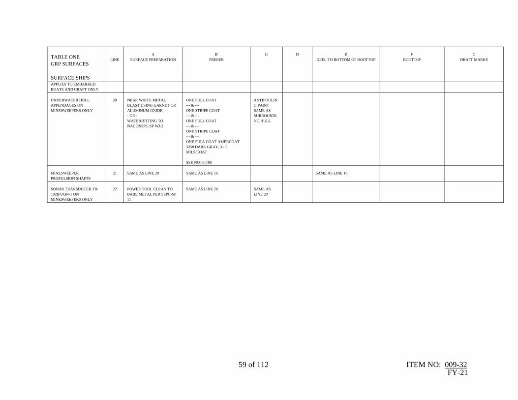
59 of 112 ITEM NO: 009-32 FY-21
TABLE ONE
GRP SURFACES
SURFACE SHIPS
LINE
A
SURFACE PREPARATION
B
PRIMER
C
D
E
KEEL TO BOTTOM OF BOOTTOP
F
BOOTTOP
G
DRAFT MARKS
APPLIES TO EMBARKED
BOATS AND CRAFT ONLY
UNDERWATER HULL
APPENDAGES ON
MINESWEEPERS ONLY
20
NEAR WHITE METAL
BLAST USING GARNET OR
ALUMINUM OXIDE
- OR -
WATERJETTING TO
NACE/SSPC-SP WJ-2
ONE FULL COAT
--- & ---
ONE STRIPE COAT
--- & ---
ONE FULL COAT
--- & ---
ONE STRIPE COAT
--- & ---
ONE FULL COAT AMERCOAT
3258 DARK GRAY, 3 - 5
MILS/COAT
SEE NOTE (40)
ANTIFOULIN
G PAINT
SAME AS
SURROUNDI
NG HULL
MINESWEEPER
PROPULSION SHAFTS
21
SAME AS LINE 20
SAME AS LINE 16
SAME AS LINE 18
SONAR TRANSDUCER TR-
192B/UQN-1 ON
MINESWEEPERS ONLY
22
POWER TOOL CLEAN TO
BARE METAL PER SSPC-SP
11
SAME AS LINE 20
SAME AS
LINE 20
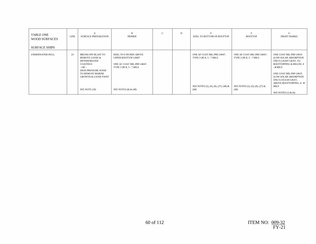
60 of 112 ITEM NO: 009-32 FY-21
TABLE ONE
WOOD SURFACES
SURFACE SHIPS
LINE
A
SURFACE PREPARATION
B
PRIMER
C
D
E
KEEL TO BOTTOM OF BOOTTOP
F
BOOTTOP
G
DRAFT MARKS
UNDERWATER HULL
23
BRUSH-OFF BLAST TO
REMOVE LOOSE &
DETERIORATED
COATINGS
- OR -
HIGH PRESSURE WASH
TO REMOVE MARINE
GROWTH & LOOSE PAINT
SEE NOTE (20)
KEEL TO 6 INCHES ABOVE
UPPER BOOTTOP LIMIT
ONE AC COAT MIL-PRF-24647,
TYPE I OR II, 5 - 7 MILS
SEE NOTES (8) & (48)
ONE AF COAT MIL-PRF-24647,
TYPE I OR II, 5 - 7 MILS
SEE NOTES (2), (6), (8), (27), (48) &
(68)
ONE AF COAT MIL-PRF-24647,
TYPE I OR II, 5 - 7 MILS
SEE NOTES (2), (6), (8), (27) &
(48)
ONE COAT MIL-PRF-24635
(LOW SOLAR ABSORPTION
ONLY) LIGHT GRAY, TO
BOOTTOPPING & BELOW, 5
- 8 MILS
ONE COAT MIL-PRF-24635
(LOW SOLAR ABSORPTION
ONLY) OCEAN GRAY,
ABOVE BOOTTOPPING, 5 - 8
MILS
SEE NOTES (1) & (6)

61 of 112 ITEM NO: 009-32
FY-21
TABLE 2
STEEL SURFACES
SURFACE SHIPS
LINE
A
SURFACE
PREPARATION
B
PRIMER
C
D
E
HORIZONTAL SURFACES
DECKS & FITTINGS
F
MASTS & STACKS
EXPOSED TO GASES
G
VERTICAL SURFACES
EXTERIOR SURFACES ABOVE BOOTTOP
WITH EXCEPTION OF AREAS RECEIVING
NONSKID & WELL DECK OVERHEAD
AREAS
SEE NOTES (2), (3), (33) & (70)
1
NEAR WHITE METAL
BLAST, NACE 2/SSPC-SP
10
- OR -
WATERJETTING TO
NACE/SSPC-SP WJ-2/M
- OR -
SSPC-SP 10/M
(WAB)/NACE WAB-2/M
ONE COAT MIL-PRF-
23236, TYPE V OR VI,
CLASS 5 OR 7, 4 - 8 MILS
ONE STRIPE COAT
-- & --
ONE FULL COAT
MIL-PRF-23236, TYPE
V OR VI, CLASS 5 OR 7,
4 - 8 MILS/COAT
ONE COAT DECK GRAY MIL-
PRF-24635 TYPE V OR VI,
CLASS 2, GRADE B OR C, 5 -8
MILS
SEE NOTES (47), (64), & (86)
ONE COAT HAZE GRAY
MIL-PRF-24635 TYPE V OR
VI, CLASS 2, GRADE B OR C,
5 - 8 MILS
- OR -
MIL-PRF-24763, TYPE II OR
III, CLASS 2, GRADE B, 2 - 4
MILS
SEE NOTES (42), (64), (85), &
(86)
ONE COAT HAZE
GRAY MIL-PRF-24635
TYPE V OR VI, CLASS
2, GRADE B OR C, 5 – 8
MILS
- OR -
MIL-PRF-24763, TYPE
II OR III, CLASS 2,
GRADE B, 2 - 4 MILS
PAINT
DESIGNATIONS &
MARKINGS MIL-PRF-
24635, 5 - 8 MILS
SEE NOTES (43), (47),
(64), (85), & (86)
2
SAME AS LINE ONE
ONE FULL COAT MIL-
PRF-23236, TYPE VII,
CLASS 5 OR 7, 4 - 8 MILS
ONE FULL COAT
MIL-PRF-23236, TYPE
VII, CLASS 5 OR 7,10 -
12 MILS
SAME AS LINE ONE
SAME AS LINE ONE
SAME AS LINE ONE
3
SAME AS LINE ONE
"SINGLE COAT"
ONE COAT MIL-PRF-
23236 TYPE VII CLASS
5/18 OR 7/18, 20 - 30 MILS
SEE NOTES (24) & (46)
SAME AS LINE ONE
SAME AS LINE ONE
SAME AS LINE ONE
4
SAME AS LINE ONE
ONE FULL COAT
ANTI-CORROSIVE MIL-
PRF-24647, TYPE I OR II,
5 - 7 MILS
SEE NOTE (8)
ONE STRIPE COAT
-- & --
ONE FULL COAT
ANTI-CORROSIVE MIL-
PRF-24647, TYPE I OR
II, 5 - 7 MILS
SEE NOTE (8)
SAME AS LINE ONE
SAME AS LINE ONE
SAME AS LINE ONE

62 of 112 ITEM NO: 009-32
FY-21
TABLE 2
STEEL SURFACES
SURFACE SHIPS
LINE
A
SURFACE
PREPARATION
B
PRIMER
C
D
E
HORIZONTAL SURFACES
DECKS & FITTINGS
F
MASTS & STACKS
EXPOSED TO GASES
G
VERTICAL SURFACES
EXTERIOR SURFACES TO BE INSULATED
5
SAME AS LINE ONE
SAME AS LINE ONE
SAME AS LINE ONE
ONE COAT MIL-PRF-23236,
TYPE V OR VI, CLASS 5 OR
7, 4 - 8 MILS
--OR--
ONE COAT MIL-PRF-24635,
TYPE V OR VI, CLASS 2,
GRADE B OR C, 5 - 8 MILS
FOLLOWED BY
INSULATION
SEE NOTES (64), & (86)
ONE COAT HAZE GRAY, MIL-
PRF-24635, TYPE V, CLASS 2
GRADE B, 5 - 8 MILS
ONE COAT HAZE
GRAY, MIL-PRF-
24635, TYPE V, CLASS
2, GRADE B, 5 - 8 MILS
6
SAME AS LINE ONE
SAME AS LINE 2
ONE COAT MIL-PRF-23236,
TYPE VII, CLASS 5 OR 7, 4 -
8 MILS
--OR--
ONE COAT MIL-PRF-24635,
TYPE V OR VI, CLASS 2,
GRADE B OR C, 5 - 8 MILS
FOLLOWED BY
INSULATION
SEE NOTES (64), & (86)
SAME AS LINE 5
SAME AS LINE 5
7
SAME AS LINE ONE
SAME AS LINE 3
ONE COAT MIL-PRF-23236,
TYPE VII, CLASS 5/18 OR
7/18, 4 - 8 MILS
--OR--
ONE COAT MIL-PRF-24635,
TYPE V OR VI, CLASS 2,
GRADE B OR C, 5 - 8 MILS
FOLLOWED BY
INSULATION
SEE NOTES (64), & (86)
SAME AS LINE 5
SAME AS LINE 5

63 of 112 ITEM NO: 009-32
FY-21
TABLE 2
STEEL SURFACES
SURFACE SHIPS
LINE
A
SURFACE
PREPARATION
B
PRIMER
C
D
E
HORIZONTAL SURFACES
DECKS & FITTINGS
F
MASTS & STACKS
EXPOSED TO GASES
G
VERTICAL SURFACES
8
SAME AS LINE ONE
SAME AS LINE 4
SAME AS LINE 4
ONE COAT ANTI-
CORROSIVE MIL-PRF-24647,
5 - 7 MILS
--OR--
ONE COAT MIL-PRF-24635,
TYPE V OR VI, CLASS 2,
GRADE B OR C, 5 - 8 MILS
FOLLOWED BY
INSULATION
SEE NOTES (8), (64), & (86)
SAME AS LINE 5
SAME AS LINE 5
HANGAR DECKS, FLIGHT DECKS &
VERTICAL REPLENISHMENT DECK AREAS
MINIMUM 3 YEARS SERVICE LIFE
SEE NOTE (75)
9
NEAR WHITE METAL
BLAST, NACE 2/SSPC-SP
10
- OR -
WATERJETTING TO
NACE/SSPC-SP WJ-2/L
- OR -
SSPC-SP
10/L(WAB)/NACE WAB-
2/L
ONE COAT
PROPRIETARY NONSKID
PRIMER LISTED ON THE
QPL FOR MIL-PRF-24667
(OF TYPE TO MATCH
COLUMN E)
SEE NOTE (7)
STRIPE COAT OF
PROPRIETARY
NONSKID PRIMER
LISTED ON THE QPL
FOR MIL-PRF-24667
SEE NOTE (7)
ONE COAT DARK GRAY, MIL-
PRF-24667, TYPE V, COMP G
SEE NOTES (19), (22), (50),
(56), (59), (61), & (63)
HANGAR DECKS, FLIGHT DECKS &
VERTICAL REPLENISHMENT DECK AREAS
MINIMUM 12 MONTHS SERVICE LIFE
10
SAME AS LINE 9
SAME AS LINE 9
SAME AS LINE 9
ONE COAT DARK GRAY, MIL-
PRF-24667, TYPE VI, OR VIII,
COMP G
SEE NOTES (19), (22), (50),
(56), (59), (61), (63), & (72)
SEE NOTE (75)
11
SAME AS LINE 9
SAME AS LINE 9
ONE FULL COAT OF
PROPRIETARY
NONSKID PRIMER
LISTED ON THE QPL
FOR MIL-PRF-24667
SEE NOTES (7) & (76)
ONE COAT DARK GRAY, MIL-
PRF-24667, TYPE I, COMP G
SEE NOTES (19), (22), (50),
(56), (59), (61), & (63)
HANGAR DECKS, FLIGHT DECKS &
VERTICAL REPLENISHMENT DECK AREAS
MINIMUM 6 MONTHS SERVICE LIFE
SEE NOTE (75)
12
SAME AS LINE 9
SAME AS LINE 9
SAME AS LINE 9
ONE COAT DARK GRAY, MIL-
PRF-24667, TYPE II, COMP G
SEE NOTES (19), (22), (50),
(56), (59), (61), & (63)

64 of 112 ITEM NO: 009-32
FY-21
TABLE 2
STEEL SURFACES
SURFACE SHIPS
LINE
A
SURFACE
PREPARATION
B
PRIMER
C
D
E
HORIZONTAL SURFACES
DECKS & FITTINGS
F
MASTS & STACKS
EXPOSED TO GASES
G
VERTICAL SURFACES
HANGAR DECKS, FLIGHT DECKS,
VERTICAL REPLENISHMENT DECK
AREAS, CVN FLIGHT DECK LANDING
AREAS, WALK AREAS AND ALL OTHER
DECK AREAS
13
POWER TOOL
CLEANING TO BARE
METAL, SSPC-SP 11
SAME AS LINE 9
SAME AS LINE 9
ONE COAT DARK GRAY,
MIL-PRF-24667, TYPE VII,
COMP G OR L
SEE NOTES (19), (22), (50),
(56), (60), (61), & (63)
MINIMUM 30 DAYS SERVICE LIFE
SEE NOTE (75)
14
SAME AS LINE 13
ONE COAT DARK GRAY,
MIL-PRF-24667, TYPE VII,
COMP G OR L
SEE NOTES (19), (22), (50),
(56), (60), (61), & (63)
CVN FLIGHT
DECK LANDING AREAS
SERVICE LIFE MINIMUM 15,000 LANDINGS
15
SAME AS LINE 9
SAME AS LINE 9
ONE COAT DARK GRAY,
MIL-PRF-24667, TYPE V,
COMP L
SEE NOTES (19), (22), (50),
(60), & (63)
CVN FLIGHT
DECK LANDING AREAS
SERVICE LIFE MINIMUM 10,000 LANDINGS
16
SAME AS LINE 9
SAME AS LINE 9
ONE COAT DARK GRAY,
MIL-PRF-24667, TYPE I, VI, OR
VIII COMP L
SEE NOTES (19), (22), (50),
(60), (63), & (72)
LHA, LHD, LPD, AND LSD FLIGHT DECK
AREAS
MINIMUM 3 YEAR SERVICE LIFE
16A
SAME AS LINE 9
SAME AS LINE 9
SAME AS LINE 9
ONE COAT DARK GRAY, MIL-
PRF-24667, TYPE V, COMP D
SEE NOTES (19), (22), (50), &
(63)
LHA, LHD, LPD, AND LSD FLIGHT DECK
AREAS
MINIMUM 12 MONTH SERVICE LIFE
16B
SAME AS LINE 9
SAME AS LINE 9
SAME AS LINE 9
ONE COAT DARK GRAY, MIL-
PRF-24667, TYPE I, COMP D
SEE NOTES (19), (22), (50),
(63), & (72)
16C
SAME AS LINE 9
SAME AS LINE 9
SAME AS LINE 11
ONE COAT DARK GRAY, MIL-
PRF-24667, TYPE I, COMP D
SEE NOTES (19), (22), (50),
(63), & (72)

65 of 112 ITEM NO: 009-32
FY-21
TABLE 2
STEEL SURFACES
SURFACE SHIPS
LINE
A
SURFACE
PREPARATION
B
PRIMER
C
D
E
HORIZONTAL SURFACES
DECKS & FITTINGS
F
MASTS & STACKS
EXPOSED TO GASES
G
VERTICAL SURFACES
LHA, LHD, LPD, AND LSD FLIGHT DECK
AREAS
MINIMUM 30 DAY SERVICE LIFE
16D
SAME AS LINE 9
SAME AS LINE 9
SAME AS LINE 9
ONE COAT DARK GRAY, MIL-
PRF-24667, TYPE VII, COMP D
SEE NOTES (19), (22), (50), &
(63)
EXTERIOR WALK AREAS (ALL DECK
AREAS OTHER THAN HANGAR DECK,
FLIGHT DECK, & VERTICAL
REPLENISHMENT DECK AREAS)
SEE NOTE (75)
17
SAME AS LINE 9
SAME AS LINE 9
SAME AS LINE 9
ONE COAT MIL-PRF-24667,
TYPE I, V, VI, OR VIII, COMP
G
-OR-
ONE COAT DARK GRAY,
MIL-PRF-24667, TYPE II, III,
IV, COMP G
SEE NOTES (19), (22), (59), &
(63)
18
SAME AS LINE 9
ONE COAT
PROPRIETARY NONSKID
PRIMER LISTED ON THE
QPL FOR MIL-PRF-24667
TYPE I, V, VI, OR VIII,
COMP G, 4-6 MILS
SEE NOTE (7)
ONE STRIPE COAT
PROPRIETARY
NONSKID PRIMER
LISTED ON THE QPL
FOR MIL-PRF-24667
TYPE I, V, VI, OR VIII,
COMP G, 4-6 MILS
SEE NOTE (7)
ONE COAT DECK GRAY MIL-
PRF-24635 TYPE V, CLASS 2,
GRADE B OR C, 5 - 8 MILS
--&--
APPLICATION OF MIL-PRF-
24667, TYPE XI, COMP PS
SEE NOTES (19), (22),(63), (70)
& (86)
19
SAME AS LINE 9
ONE COAT MIL-PRF-
23236, TYPE V OR VI
CLASS 5, 4-6 MILS
ONE STRIPE COAT
MIL-PRF-23236, TYPE V
OR VI CLASS 5, 4-6
MILS
SAME AS LINE 18
20
SAME AS LINE 9
ONE COAT MIL-PRF-
23236, TYPE VII CLASS 5,
15B, OR 17, 6-8 MILS
SAME AS LINE 18
21
SAME AS LINE 13
ONE COAT MIL-PRF-
23236, TYPE V OR VI
CLASS 5, 4-6 MILS
ONE STRIPE COAT
MIL-PRF-23236, TYPE V
OR VI CLASS 5, 4-6
MILS
SAME AS LINE 18
22
SAME AS LINE 13
ONE COAT MIL-PRF-
23236, TYPE VII CLASS
15B OR 17, 6-8 MILS
SAME AS LINE 18

66 of 112 ITEM NO: 009-32
FY-21
TABLE 2
STEEL SURFACES
SURFACE SHIPS
LINE
A
SURFACE
PREPARATION
B
PRIMER
C
D
E
HORIZONTAL SURFACES
DECKS & FITTINGS
F
MASTS & STACKS
EXPOSED TO GASES
G
VERTICAL SURFACES
RAST TRACK TROUGHS WHERE PAINTED
(WHERE NONSKID NOT APPLIED)
23
NEAR WHITE METAL
BLAST, NACE 2/SSPC-SP
10
- OR -
WATERJETTING TO
NACE/SSPC-SP WJ-2/L
-OR-
POWER TOOL CLEAN TO
BARE METAL, SSPC-SP
11
- OR -
SSPC-SP 10/L
(WAB)/NACE WAB-2/L
ONE COAT MIL-PRF-
23236, TYPE VII, CLASS
17, 6 - 8 MILS
--OR--
ONE COAT MIL-PRF-
23236, TYPE VII, CLASS
15B, 6 - 8 MILS
ONE COAT MIL-PRF-23236,
TYPE VII, CLASS 17, 6 - 8
MILS
--OR--
ONE COAT MIL-PRF-23236,
TYPE VII, CLASS 15B, 6 - 8
MILS
24
SAME AS LINE ONE
"SINGLE COAT"
ONE COAT MIL-PRF-
23236 TYPE VII CLASS
17/18, 20-30 MILS
SEE NOTES (24) & (46)
25
SAME AS LINE ONE
ONE COAT MIL-PRF-
23236, TYPE VII, CLASS
5, 4-8 MILS
ONE COAT MIL-PRF-23236,
TYPE VII, CLASS 5, 10-12
MILS
CVN CATAPULT TROUGHS
25A
NEAR WHITE METAL
BLAST, NACE 2/SSPC-SP
10
SEE NOTE (30)
“SINGLE COAT”
ONE COAT MIL-PRF-
23236, TYPE VII, CLASS
19/18, 20-30 MILS
WELL DECK OVERHEADS, BOTH EXPOSED
& NON-EXPOSED TO LCAC EXHAUST,
AND ENCLOSED BOAT HANDLING AREA
OVERHEADS
SEE NOTE (34)
26
NEAR WHITE METAL
BLAST, NACE 2/SSPC-SP
10
SEE NOTES (30) & (31)
ONE COAT MIL-PRF-
23236, TYPE VII, CLASS
19,
4 - 8 MILS
SEE NOTE (49)
ONE COAT MIL-PRF-23236,
TYPE VII, CLASS 19, 10 - 12
MILS
SEE NOTE (49)
27
SAME AS LINE 26
"SINGLE COAT"
ONE COAT MIL-PRF-
23236 TYPE VII CLASS
19/18, 20-30 MILS
SEE NOTES (24) & (46)
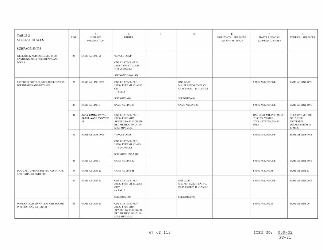
67 of 112 ITEM NO: 009-32
FY-21
TABLE 2
STEEL SURFACES
SURFACE SHIPS
LINE
A
SURFACE
PREPARATION
B
PRIMER
C
D
E
HORIZONTAL SURFACES
DECKS & FITTINGS
F
MASTS & STACKS
EXPOSED TO GASES
G
VERTICAL SURFACES
WELL DECK AND ENCLOSED BOAT
HANDLING AREA BULKHEADS AND
DECKS
28
SAME AS LINE 26
"SINGLE COAT"
ONE COAT MIL-PRF-
23236 TYPE VII CLASS
7/18, 20-30 MILS
SEE NOTE (24) & (46)
EXTERIOR PORTABLE/BOLTED LOUVERS
FOR INTAKES AND UPTAKES
29
SAME AS LINE ONE
ONE COAT MIL-PRF-
23236, TYPE VII, CLASS 5
OR 7,
4 - 8 MILS
SEE NOTE (49)
ONE COAT
MIL-PRF-23236, TYPE VII,
CLASS 5 OR 7, 10 - 12 MILS
SEE NOTE (49)
SAME AS LINE ONE
SAME AS LINE ONE
30
SAME AS LINE 9
SAME AS LINE 29
SAME AS LINE 29
SAME AS LINE ONE
SAME AS LINE ONE
31
NEAR WHITE METAL
BLAST, NACE 2/SSPC-SP
10
ONE COAT MIL-PRF-
23236, TYPE VIIIA
APPLIED BY FLUIDIZED
BED METHOD ONLY, 10
MILS MINIMUM
ONE COAT MIL-PRF-24712,
TGIC POLYESTER,
TOTAL SYSTEM 15 - 30
MILS
ONE COAT MIL-PRF-
24712, TGIC
POLYESTER,
TOTAL SYSTEM 15 -
30 MILS
32
SAME AS LINE ONE
"SINGLE COAT"
ONE COAT MIL-PRF-
23236, TYPE VII, CLASS
7/18, 20-30 MILS
SEE NOTES (24) & (46)
SAME AS LINE ONE
SAME AS LINE ONE
33
SAME AS LINE 9
SAME AS LINE 32
SAME AS LINE ONE
SAME AS LINE ONE
DDG GAS TURBINE BOLTED AIR INTAKE
AND EXHAUST LOUVERS
34
SAME AS LINE 31
SAME AS LINE 31
SAME AS LINE 31
SAME AS LINE 31
35
SAME AS LINE 31
ONE COAT MIL-PRF-
23236, TYPE VII, CLASS 5
OR 7,
4 - 8 MILS
SEE NOTE (49)
ONE COAT
MIL-PRF-23236, TYPE VII,
CLASS 5 OR 7, 10 - 12 MILS
SEE NOTE (49)
SAME AS LINE ONE
SAME AS LINE ONE
POWDER COATED WATERTIGHT DOORS:
INTERIOR AND EXTERIOR
36
SAME AS LINE 31
ONE COAT MIL-PRF-
23236, TYPE VIIIA
APPLIED BY FLUIDIZED
BED METHOD ONLY, 10
MILS MINIMUM
SAME AS LINE 26
SAME AS LINE 26
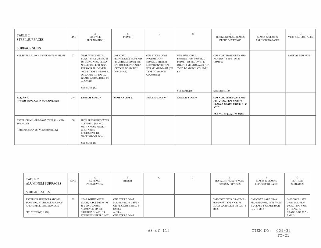
68 of 112 ITEM NO: 009-32
FY-21
TABLE 2
STEEL SURFACES
SURFACE SHIPS
LINE
A
SURFACE
PREPARATION
B
PRIMER
C
D
E
HORIZONTAL SURFACES
DECKS & FITTINGS
F
MASTS & STACKS
EXPOSED TO GASES
G
VERTICAL SURFACES
VERTICAL LAUNCH SYSTEM (VLS), MK-41
37
NEAR WHITE METAL
BLAST, NACE 2/SSPC-SP
10, USING NEW, CLEAN,
NON-RECYCLED, NON-
FERROUS ALUMINUM
OXIDE TYPE I, GRADE A
OR GARNET, TYPE IV,
GRADE A QUALIFIED TO
A-A-59316
SEE NOTE (82)
ONE COAT
PROPRIETARY NONSKID
PRIMER LISTED ON THE
QPL FOR MIL-PRF-24667
(OF TYPE TO MATCH
COLUMN E)
ONE STRIPE COAT
PROPRIETARY
NONSKID PRIMER
LISTED ON THE QPL
FOR MIL-PRF-24667 (OF
TYPE TO MATCH
COLUMN E)
ONE FULL COAT
PROPRIETARY NONSKID
PRIMER LISTED ON THE
QPL FOR MIL-PRF-24667 (OF
TYPE TO MATCH COLUMN
E)
SEE NOTE (16)
ONE COAT HAZE GRAY MIL-
PRF-24667, TYPE I OR II,
COMP G
SEE NOTE (19)
SAME AS LINE ONE
VLS, MK-41
(WHERE NONSKID IN NOT APPLIED)
37A
SAME AS LINE 37
SAME AS LINE 37
SAME AS LINE 37
SAME AS LINE 37
ONE COAT HAZE GRAY MIL-
PRF-24635, TYPE V OR VI,
CLASS 2, GRADE B OR C, 5 - 8
MILS
SEE NOTES (23), (70), & (85)
EXTERIOR MIL-PRF-24667 (TYPES I – VIII)
SURFACES
(GREEN CLEAN OF NONSKID DECK)
38
HIGH PRESSURE WATER
CLEANING (HP WC)
WITH VACUUM SELF-
CONTAINED
EQUIPMENT TO
NACE/SSPC-SP WJ-4
SEE NOTE (80)
TABLE 2
ALUMINUM SURFACES
SURFACE SHIPS
LINE
A
SURFACE
PREPARATION
B
PRIMER
C
D
E
HORIZONTAL SURFACES
DECKS & FITTINGS
F
MASTS & STACKS
EXPOSED TO GASES
G
VERTICAL
SURFACES
EXTERIOR SURFACES ABOVE
BOOTTOP, WITH EXCEPTION OF
AREAS RECEIVING NONSKID
SEE NOTES (2) & (70)
39
NEAR WHITE METAL
BLAST, NACE 2/SSPC-SP
10 USING GARNET,
ALUMINUM OXIDE,
CRUSHED GLASS, OR
STAINLESS STEEL SHOT
ONE STRIPE COAT
MIL-PRF-23236, TYPE V
OR VI, CLASS 5 OR 7, 4 -
8 MILS
-- OR --
ONE STRIPE COAT
ONE COAT DECK GRAY MIL-
PRF-24635, TYPE V OR VI,
CLASS 2, GRADE B OR C, 5 - 8
MILS
ONE COAT HAZE GRAY
MIL-PRF-24635, TYPE V OR
VI, CLASS 2, GRADE B OR
C, 5 - 8 MILS
ONE COAT HAZE
GRAY MIL-PRF-
24635, TYPE V OR
VI, CLASS 2,
GRADE B OR C, 5 -
8 MILS

69 of 112 ITEM NO: 009-32
FY-21
TABLE 2
ALUMINUM SURFACES
SURFACE SHIPS
LINE
A
SURFACE
PREPARATION
B
PRIMER
C
D
E
HORIZONTAL SURFACES
DECKS & FITTINGS
F
MASTS & STACKS
EXPOSED TO GASES
G
VERTICAL
SURFACES
- OR -
WATERJETTING TO
NACE/SSPC-SP WJ-2
SEE NOTES (89) & (91)
MIL-PRF-23236, TYPE
VII, CLASS 5 OR 7, 6 - 10
MILS
--OR—
ONE STRIPE COAT
MIL-PRF-23236, TYPE
VII, CLASS 5/18 OR 7/18,
10 - 15 MILS
--OR—
ONE STRIPE COAT
MIL-PRF-24635, TYPE V
OR VI, CLASS 2, 5 - 8
MILS
SEE NOTE (86)
SEE NOTE (86)
SEE NOTE (86)
IDENTIFICATION
MARKINGS:
PAINT
DESIGNATIONS &
MARKINGS MIL-
PRF-24635, 5 - 8
MILS
SEE NOTE (86)
HANGAR DECKS, FLIGHT DECKS,
AIRCRAFT ELEVATOR PLATFORM
DECKS & VERTICAL
REPLENISHMENT DECK AREAS
MINIMUM 3 YEARS SERVICE LIFE
SEE NOTE (75) & (93)
40
SAME AS LINE 39
SEE NOTE (92)
ONE COAT
PROPRIETARY
NONSKID PRIMER
LISTED ON THE QPL
FOR MIL-PRF-24667 (OF
TYPE TO MATCH
COLUMN E) WILL BE
APPLIED WITHIN 6
HOURS AFTER SURFACE
PREPARATION
SEE NOTES (5) & (7)
ONE COAT DARK GRAY,
MIL-PRF-24667, TYPE V,
COMP G
SEE NOTES (19), (22), (50),
(56), (59), (61), & (63)
HANGAR DECKS, FLIGHT DECKS,
AIRCRAFT ELEVATOR PLATFORM
DECKS & VERTICAL
REPLENISHMENT DECK AREAS
MINIMUM 12 MONTHS SERVICE
LIFE
SEE NOTE (75) & (93)
41
SAME AS LINE 39
SEE NOTE (92)
SAME AS LINE 40
ONE COAT DARK GRAY MIL-
PRF-24667, TYPE I, VI, OR
VIII, COMP G
SEE NOTES (19), (22), (50),
(56), (59), (61), (63), & (72)

70 of 112 ITEM NO: 009-32
FY-21
TABLE 2
ALUMINUM SURFACES
SURFACE SHIPS
LINE
A
SURFACE
PREPARATION
B
PRIMER
C
D
E
HORIZONTAL SURFACES
DECKS & FITTINGS
F
MASTS & STACKS
EXPOSED TO GASES
G
VERTICAL
SURFACES
HANGAR DECKS, FLIGHT DECKS,
AIRCRAFT ELEVATOR PLATFORM
DECKS & VERTICAL
REPLENISHMENT DECK AREAS
MINIMUM 6 MONTHS SERVICE
LIFE
SEE NOTE (75) & (93)
42
SAME AS LINE 39
SEE NOTE (92)
SAME AS LINE 40
ONE COAT DARK GRAY MIL-
PRF-24667 TYPE II, COMP G
SEE NOTES (19), (22), (50),
(56), (59), (61), & (63)
HANGAR DECKS, FLIGHT DECKS,
AIRCRAFT ELEVATOR PLATFORM
DECKS, VERTICAL
REPLENISHMENT DECK AREAS,
CVN FLIGHT DECK LANDING
AREAS, WALK AREAS AND ALL
OTHER DECK AREAS
MINIMUM 30 DAYS SERVICE LIFE
SEE NOTE (75)
43
POWER TOOL CLEAN
TO BARE METAL, SSPC-
SP 11
SEE NOTE (90)
SAME AS LINE 40
ONE COAT DARK GRAY,
MIL-PRF-24667, TYPE VII,
COMP G OR L
SEE NOTES (19), (22), (50),
(56), (60), (61), & (63)
44
SAME AS LINE 43
ONE COAT DARK GRAY,
MIL-PRF-24667, TYPE VII,
COMP G OR L
SEE NOTES (19), (22), (50),
(56), (60), (61), & (63)

71 of 112 ITEM NO: 009-32
FY-21
TABLE 2
ALUMINUM SURFACES
SURFACE SHIPS
LINE
A
SURFACE
PREPARATION
B
PRIMER
C
D
E
HORIZONTAL SURFACES
DECKS & FITTINGS
F
MASTS & STACKS
EXPOSED TO GASES
G
VERTICAL
SURFACES
EXTERIOR WALK AREAS (ALL
DECK AREAS OTHER
THAN HANGAR DECK, FLIGHT
DECK,
& VERTICAL REPLENISHMENT
DECK AREAS)
SEE NOTE (75)
45
SAME AS LINE 39
SAME AS LINE 40
ONE COAT MIL-PRF-24667,
TYPE I, V, VI, OR VIII, COMP
G
-OR-
ONE COAT DARK GRAY,
MIL-PRF-24667, TYPE II, III,
IV, COMP G
SEE NOTES (19), (22), (59), &
(63)
46
SAME AS LINE 39
ONE STRIPE COAT
PROPRIETARY
NONSKID PRIMER
LISTED ON THE QPL
FOR MIL-PRF-24667
TYPE I, V, OR VI COMP
G, 4-6 MILS
SEE NOTE (7)
ONE COAT DECK GRAY MIL-
PRF-24635, TYPE V OR VI,
CLASS 2, GRADE B OR C, 2 - 3
MILS, OR TYPE V, 5 - 8 MILS
-- & --
APPLICATION OF MIL-PRF-
24667, TYPE XI, COMP PS
SEE NOTES (19), (22), (63) &
(86)
47
SAME AS LINE 39
ONE COAT MIL-PRF-
23236, TYPE V, VI, OR VII
CLASS 5, 15B, OR 17, 4-6
MILS
SAME AS LINE 46
48
SAME AS LINE 43
SEE NOTE (5)
ONE COAT MIL-PRF-
23236, TYPE V, VI, OR VII
CLASS 15B OR 17, 6 - 8
MILS
SAME AS LINE 46
RAST TRACK TROUGHS WHERE
PAINTED (WHERE NONSKID NOT
APPLIED
49
NEAR WHITE METAL
BLAST, NACE 2/SSPC-SP
10 USING GARNET,
ALUMINUM OXIDE, OR
CRUSHED GLASS
- OR -
WATERJETTING TO
NACE/SSPC-SP WJ-2/L
-OR-
POWER TOOL CLEAN
TO BARE METAL, SSPC-
SP 11
SEE NOTES (89), (90), &
(91)
ONE COAT MIL-PRF-
23236, TYPE VII, CLASS
15B OR 17, 6 - 8 MILS
ONE COAT MIL-PRF-23236,
TYPE VII, CLASS 15B OR 17,
6 - 8 MILS

72 of 112 ITEM NO: 009-32
FY-21
TABLE 2
ALUMINUM SURFACES
SURFACE SHIPS
LINE
A
SURFACE
PREPARATION
B
PRIMER
C
D
E
HORIZONTAL SURFACES
DECKS & FITTINGS
F
MASTS & STACKS
EXPOSED TO GASES
G
VERTICAL
SURFACES
50
SAME AS LINE 39
"SINGLE COAT"
ONE COAT MIL-PRF-
23236 TYPE VII CLASS
17/18, 20-30 MILS
SEE NOTES (24) & (46)
51
SAME AS LINE 39
ONE COAT MIL-PRF-
23236, TYPE VII, CLASS
5, 4-8 MILS
ONE COAT MIL-PRF-23236,
TYPE VII, CLASS 5, 10-12
MILS
EXTERIOR PORTABLE/BOLTED
LOUVERS FOR INTAKES AND
UPTAKES
52
SAME AS LINE 39
ONE COAT
MIL-PRF-23236, TYPE
VII, CLASS 5 OR 7, 4 - 8
MILS
SEE NOTE (49)
ONE COAT MIL-PRF-23236,
TYPE VII, CLASS 5 OR 7, 10 -
12 MILS
SEE NOTE (49)
SAME AS LINE 39
SAME AS LINE 39
53
SAME AS LINE 39
SAME AS LINE 52
SAME AS LINE 52
SAME AS LINE 39
SAME AS LINE 39
54
SAME AS LINE 43
ONE COAT MIL-PRF-
23236, TYPE VIIIA
APPLIED BY FLUIDIZED
BED METHOD ONLY, 10
MILS MINIMUM
ONE COAT MIL-PRF-24712,
TGIC POLYESTER,
TOTAL SYSTEM 15 - 30
MILS
ONE COAT MIL-
PRF-24712, TGIC
POLYESTER,
TOTAL SYSTEM
15 - 30 MILS
55
SAME AS LINE 39
"SINGLE COAT"
ONE COAT MIL-PRF-
23236, TYPE VII, CLASS
7/18, 20-30 MILS
SEE NOTES (24) & (46)
SAME AS LINE 39
SAME AS LINE 39
56
SAME AS LINE 39
SAME AS LINE 55
SAME AS LINE 39
SAME AS LINE 39

73 of 112 ITEM NO: 009-32
FY-21
TABLE 2
ALUMINUM SURFACES
SURFACE SHIPS
LINE
A
SURFACE
PREPARATION
B
PRIMER
C
D
E
HORIZONTAL SURFACES
DECKS & FITTINGS
F
MASTS & STACKS
EXPOSED TO GASES
G
VERTICAL
SURFACES
VERTICAL LAUNCH SYSTEM
(VLS), MK-41
57
NEAR WHITE METAL
BLAST, NACE 2/SSPC-SP
10, USING NEW, CLEAN,
NON-RECYCLED, NON-
FERROUS ALUMINUM
OXIDE TYPE I, GRADE A
OR GARNET, TYPE IV,
GRADE A QUALIFIED
TO A-A-59316
SEE NOTES (82) & (89)
ONE COAT
PROPRIETARY
NONSKID PRIMER
LISTED ON THE QPL
FOR MIL-PRF-24667 (OF
TYPE TO MATCH
COLUMN E)
ONE FULL COAT
PROPRIETARY NONSKID
PRIMER LISTED ON THE
QPL FOR MIL-PRF-24667 (OF
TYPE TO MATCH COLUMN
E)
SEE NOTE (16)
ONE COAT HAZE GRAY MIL-
PRF-24667, TYPE I OR II,
COMP G
SEE NOTE (19)
VLS, MK-41
(WHERE NONSKID IS NOT
APPLIED)
57A
SAME AS LINE 39
SAME AS LINE 40
SAME AS LINE 40
ONE COAT HAZE GRAY MIL-
PRF-24635, TYPE V OR VI,
CLASS 2, GRADE B OR C, 5 – 8
MILS
SEE NOTES (23), (70) & (85)
EXTERIOR MIL-PRF-24667 (TYPES I
– VIII) SURFACES
(GREEN CLEAN OF NONSKID
DECKS INCLUDING FLIGHT DECK)
58
HIGH PRESSURE WATER
CLEANING (HP WC)
WITH VACUUM SELF-
CONTAINED
EQUIPMENT TO
NACE/SSPC-SP WJ-4
SEE NOTE (80)

74 of 112 ITEM NO: 009-32
FY-21
TABLE 2
GRP FIBERGLASS
SURFACES
SURFACE SHIPS
LINE
A
SURFACE PREPARATION
B
PRIMER
C
D
E
HORIZONTAL SURFACES
DECKS & FITTINGS
F
MASTS & STACKS EXPOSED
TO GASES
G
VERTICAL SURFACES
EXTERIOR SURFACES ABOVE
BOOTTOP
SEE NOTES (2) & (70)
59
HIGH PRESSURE WASH
TO REMOVE MARINE
GROWTH & LOOSE
PAINT
- OR -
TOUCH-UP OR
REMOVAL OF PAINT
SYSTEM TO SOUND
PRIMER BY LIGHT
ABRASIVE BLASTING
WITH WALNUT SHELLS
-- & --
SPOT CLEAN, CHAP 631,
PARA 631-5.2.6
SEE NOTE (21)
ONE COAT F-150,
MIL-DTL-24441, TYPE IV,
4 - 6 MILS
SEE NOTE (29)
ONE STRIPE COAT
MIL-DTL-24441, TYPE IV,
4 - 6 MILS
-- & --
ONE COAT MIL-DTL-24441,
TYPE IV, 4 - 6 MILS
SEE NOTE (29)
ONE COAT DECK GRAY MIL-
PRF-24635 TYPE V, CLASS 2,
GRADE B OR C, 5 - 8 MILS
ONE COAT HAZE GRAY
MIL-PRF-24635 TYPE V,
GRADE B, 5 - 8 MILS
- OR -
MIL-PRF-24763, TYPE II OR
III, CLASS 2, GRADE B, 2 - 4
MILS
SEE NOTES (42) & (85)
ONE COAT HAZE GRAY
MIL-PRF-24635 TYPE V,
GRADE B, 5 - 8 MILS
- OR -
MIL-PRF-24763, TYPE II OR
III, CLASS 2, GRADE B, 2 - 4
MILS
IDENTIFICATION
MARKINGS:
PAINT DESIGNATIONS &
MARKINGS MIL-PRF-24635,
5 - 8 MILS
SEE NOTES (43) & (85)
EXTERIOR WALK AREAS
ALL EXTERIOR DECK AREAS
60
POWER TOOL CLEAN TO
CLEAN FIBERGLASS
(DISC SANDER, ETC.)
- OR -
POWER TOOL CLEAN TO
POLYURETHANE
OVERLAY SUBSTRATE
(DISC SANDER, ETC.)
- OR -
HYDROBLAST TO
CLEAN FIBERGLASS
SEE NOTES (25) & (62)
PROPRIETARY NONSKID
PRIMER LISTED ON THE
QPL FOR MIL-PRF-24667
SEE NOTE (7)
ONE COAT
MIL-PRF-24667, TYPE I, II, OR
III, COMP G
- OR -
MIL-PRF-24667 TYPE IV
SEE NOTES (19) & (22)
61
SAME AS LINE 60
ONE COAT F-150,
MIL-DTL-24441, TYPE IV,
4 - 6 MILS
ONE COAT DECK GRAY MIL-
PRF-24635 TYPE V, GRADE B,
5 - 8 MILS
--&--
APPLICATION OF MIL-PRF-
24667, TYPE XI,
COMPOSITION PS
SEE NOTE (19)

75 of 112 ITEM NO: 009-32
FY-21
TABLE 2
WOOD SURFACES
SURFACE SHIPS
LINE
A
SURFACE PREPARATION
B
PRIMER
C
D
E
HORIZONTAL SURFACES
DECKS & FITTINGS
F
MASTS & STACKS EXPOSED
TO GASES
G
VERTICAL SURFACES
EXTERIOR ABOVE
BOOTTOPPING
62
HAND TOOL CLEAN
- OR -
POWER TOOL CLEAN TO
REMOVE
DETERIORATED
COATINGS
ONE COAT F-150,
MIL-DTL-24441, TYPE IV,
4 - 6 MILS
DECKS, MASTS &
SPARS:
ONE COAT DECK
GRAY MIL-PRF-24635
TYPE V, GRADE B, 5 - 8
MILS
- OR -
ONE COAT BLACK
MIL-PRF-24635, TYPE
V, GRADE B, 5 - 8 MILS
ALL OTHER SURFACES:
ONE COAT HAZE GRAY
MIL-PRF-24635 TYPE V,
GRADE B, 5 - 8 MILS
IDENTIFICATION
MARKINGS:
PAINT DESIGNATIONS &
MARKINGS MIL-PRF-24635,
5 - 8 MILS
SEE NOTE (43)

76 of 112 ITEM NO: 009-32
FY-21
TABLE 3
STEEL SURFACES
SURFACE SHIPS
LINE
A
SURFACE PREPARATION
B
PRIMER
C
D
BULKHEADS &
OVERHEADS
E
DECKS
F
INSULATION
G
MARKINGS
INTERIOR COMPARTMENTS
SEE NOTE (17)
1
HAND TOOL CLEANING,
SSPC-SP 2
SEE NOTE (28)
2 COATS FORMULA 84, TT-P-
645, ALKYD, 2 - 4 MILS/COAT
- OR -
ONE COAT MIL-PRF-23236,
TYPE V, VI, OR VII, CLASS 5 OR
7, 4 - 8 MILS
--OR--
ONE COAT MIL-PRF-32584,
TYPE I OR II, 10 – 12 MILS
SEE NOTE (88)
2 COATS MIL-PRF-24596,
WATER-BASED INTERIOR
LATEX, 2 - 4 MILS/COAT
- OR -
2 COATS MIL-DTL-24607,
2 - 4 MILS/COAT
SEE NOTE (9)
TO DECKS NOT RECEIVING
COVERING:
ONE COAT MIL-PRF-32584,
TYPE I OR II, 10 – 12 MILS
SEE NOTE (88)
HULL, VENTILATION & PIPING
INSULATION
ONE COAT MIL-PRF-24596,
WATER-BASED INTERIOR LATEX,
2 - 4 MILS
- OR -
ONE COAT MIL-DTL-24607,
2 - 4 MILS
IF REQUIRED FOR HIDING, ONE
ADDITIONAL COAT MUST BE
APPLIED.
SEE NOTES (9), (28) & (41)
FOR COMPARTMENT
PIPING &
VENTILATION
SEE NOTE (18)
INTERIOR COMPARTMENTS
(OVERCOAT)
SEE NOTE (17)
2
SAME AS LINE ONE
SAME AS LINE ONE FOR BARE
METAL AREAS
SAME AS LINE ONE EXCEPT
ONE COAT
SAME AS LINE ONE
SAME AS LINE ONE
SAME AS LINE ONE
WELDING BAYS AND LIGHT
TRAPS
3
SAME AS LINE ONE
SAME AS LINE ONE
ONE COAT BLACK, LOW
GLOSS, MIL-PRF-23236,
TYPE V VI, OR VII, 4 - 8
MILS
ONE COAT BLACK, SEMI-
GLOSS, MIL-PRF-23236, TYPE V
VI, OR VII, 4 - 8 MILS
- OR -
ONE COAT MIL-PRF-32584,
TYPES I OR II, 10 – 12 MILS
SEE NOTE (88)
WET SPACES (WASH ROOMS,
WATER CLOSETS, SHOWER
STALLS, GALLEYS, SCULLERIES,
& STOREROOMS WHERE HEAVY
CONDENSATION IS COMMON)
4
POWER TOOL CLEAN TO
BARE METAL, SSPC-SP 11
(DECKS)
POWER TOOL CLEANING,
SSPC-SP 3 (BULKHEADS/
OVERHEADS)
SEE NOTE (28)
"SINGLE COAT"
ONE COAT MIL-PRF-23236,
TYPE VII, CLASS 17/18,
20-30 MILS
SEE NOTES (24) & (46)
SAME AS LINE ONE
SAME AS LINE ONE
5
SAME AS LINE 4
ONE COAT MIL-PRF-23236,
TYPE VII, CLASS 15B OR 17, 6 -
8 MILS
--OR--
ONE COAT MIL-PRF-32584,
TYPE II, 10 – 12 MILS
SEE NOTE (88)
ONE COAT MIL-PRF-23236,
TYPE VII, CLASS 15B or 17, 6
- 8 MILS
TO DECKS NOT RECEIVING
COVERING:
ONE COAT MIL-PRF-32584,
TYPE II, 10 – 12 MILS
SEE NOTE (88)
SAME AS LINE ONE
SAME AS LINE ONE
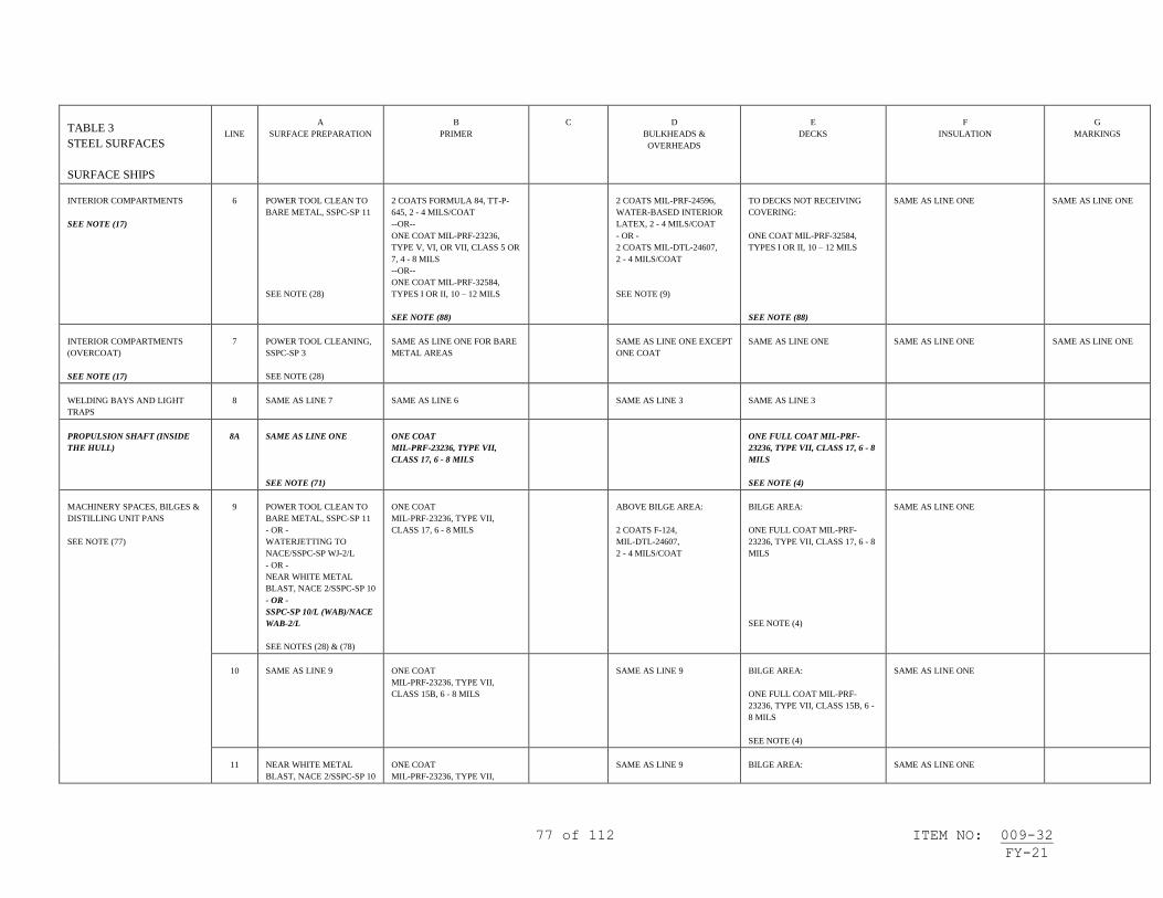
77 of 112 ITEM NO: 009-32
FY-21
TABLE 3
STEEL SURFACES
SURFACE SHIPS
LINE
A
SURFACE PREPARATION
B
PRIMER
C
D
BULKHEADS &
OVERHEADS
E
DECKS
F
INSULATION
G
MARKINGS
INTERIOR COMPARTMENTS
SEE NOTE (17)
6
POWER TOOL CLEAN TO
BARE METAL, SSPC-SP 11
SEE NOTE (28)
2 COATS FORMULA 84, TT-P-
645, 2 - 4 MILS/COAT
--OR--
ONE COAT MIL-PRF-23236,
TYPE V, VI, OR VII, CLASS 5 OR
7, 4 - 8 MILS
--OR--
ONE COAT MIL-PRF-32584,
TYPES I OR II, 10 – 12 MILS
SEE NOTE (88)
2 COATS MIL-PRF-24596,
WATER-BASED INTERIOR
LATEX, 2 - 4 MILS/COAT
- OR -
2 COATS MIL-DTL-24607,
2 - 4 MILS/COAT
SEE NOTE (9)
TO DECKS NOT RECEIVING
COVERING:
ONE COAT MIL-PRF-32584,
TYPES I OR II, 10 – 12 MILS
SEE NOTE (88)
SAME AS LINE ONE
SAME AS LINE ONE
INTERIOR COMPARTMENTS
(OVERCOAT)
SEE NOTE (17)
7
POWER TOOL CLEANING,
SSPC-SP 3
SEE NOTE (28)
SAME AS LINE ONE FOR BARE
METAL AREAS
SAME AS LINE ONE EXCEPT
ONE COAT
SAME AS LINE ONE
SAME AS LINE ONE
SAME AS LINE ONE
WELDING BAYS AND LIGHT
TRAPS
8
SAME AS LINE 7
SAME AS LINE 6
SAME AS LINE 3
SAME AS LINE 3
PROPULSION SHAFT (INSIDE
THE HULL)
8A
SAME AS LINE ONE
SEE NOTE (71)
ONE COAT
MIL-PRF-23236, TYPE VII,
CLASS 17, 6 - 8 MILS
ONE FULL COAT MIL-PRF-
23236, TYPE VII, CLASS 17, 6 - 8
MILS
SEE NOTE (4)
MACHINERY SPACES, BILGES &
DISTILLING UNIT PANS
SEE NOTE (77)
9
POWER TOOL CLEAN TO
BARE METAL, SSPC-SP 11
- OR -
WATERJETTING TO
NACE/SSPC-SP WJ-2/L
- OR -
NEAR WHITE METAL
BLAST, NACE 2/SSPC-SP 10
- OR -
SSPC-SP 10/L (WAB)/NACE
WAB-2/L
SEE NOTES (28) & (78)
ONE COAT
MIL-PRF-23236, TYPE VII,
CLASS 17, 6 - 8 MILS
ABOVE BILGE AREA:
2 COATS F-124,
MIL-DTL-24607,
2 - 4 MILS/COAT
BILGE AREA:
ONE FULL COAT MIL-PRF-
23236, TYPE VII, CLASS 17, 6 - 8
MILS
SEE NOTE (4)
SAME AS LINE ONE
10
SAME AS LINE 9
ONE COAT
MIL-PRF-23236, TYPE VII,
CLASS 15B, 6 - 8 MILS
SAME AS LINE 9
BILGE AREA:
ONE FULL COAT MIL-PRF-
23236, TYPE VII, CLASS 15B, 6 -
8 MILS
SEE NOTE (4)
SAME AS LINE ONE
11
NEAR WHITE METAL
BLAST, NACE 2/SSPC-SP 10
ONE COAT
MIL-PRF-23236, TYPE VII,
SAME AS LINE 9
BILGE AREA:
SAME AS LINE ONE

78 of 112 ITEM NO: 009-32
FY-21
TABLE 3
STEEL SURFACES
SURFACE SHIPS
LINE
A
SURFACE PREPARATION
B
PRIMER
C
D
BULKHEADS &
OVERHEADS
E
DECKS
F
INSULATION
G
MARKINGS
SEE NOTES (28) & (78)
CLASS 5, 4 - 8 MILS
SEE NOTE (49)
ONE FULL COAT MIL-PRF-
23236, TYPE VII, CLASS 5, 10 -
12 MILS
SEE NOTES (4) & (49)
12
SAME AS LINE 11
"SINGLE COAT"
ONE COAT MIL-PRF-23236
TYPE VII CLASS 5/18, 20-30
MILS
SEE NOTES (24) & (46)
SAME AS LINE 9
SAME AS LINE ONE
13
SAME AS LINE 4
"SINGLE COAT"
ONE COAT MIL-PRF-23236
TYPE VII CLASS 17/18, 20-30
MILS
SEE NOTES (24) & (46)
SAME AS LINE 9
SAME AS LINE ONE
VENT PLENUMS
14
SAME AS LINE 11
ONE COAT MIL-PRF-23236,
TYPE VII, CLASS 5, 4 - 8 MILS
SEE NOTE (49)
ONE FULL COAT HAZE
GRAY OR LIGHT GRAY
MIL-PRF-23236, TYPE VII,
CLASS 5, 10 - 12 MILS
SEE NOTE (49)
ONE FULL COAT HAZE GRAY
OR LIGHT GRAY MIL-PRF-
23236, TYPE VII, CLASS 5, 10 -
12 MILS
SEE NOTE (49)
TWO COATS MIL-PRF-24596
GRADE A WATER BASED LATEX,
GRAY, AS REQUIRED FOR HIDING
(OVER INSTALLED INSULATION)
15
SAME AS LINE 11
"SINGLE COAT"
ONE COAT MIL-PRF-23236
TYPE VII CLASS 5/18, 20-30
MILS
SEE NOTES (24), (46) & (79)
SAME AS LINE 14
16
WATERJETTING TO
NACE/SSPC-SP WJ-2/L
-OR-
NEAR WHITE METAL
BLAST,
NACE 2/SSPC-SP 10
- OR -
SSPC-SP 10/L (WAB)/NACE
WAB-2/L
ONE COAT MIL-PRF-23236,
TYPE VII, CLASS 15B OR 17, 6 -
8 MILS
ONE FULL COAT HAZE
GRAY OR LIGHT GRAY
MIL-PRF-23236, TYPE VII,
CLASS 15B OR 17, 6 - 8 MILS
ONE FULL COAT HAZE GRAY
OR LIGHT GRAY MIL-PRF-
23236, TYPE VII, CLASS 15B OR
17, 6 - 8 MILS
SAME AS LINE 14
17
SAME AS LINE 16
"SINGLE COAT"
SAME AS LINE 14
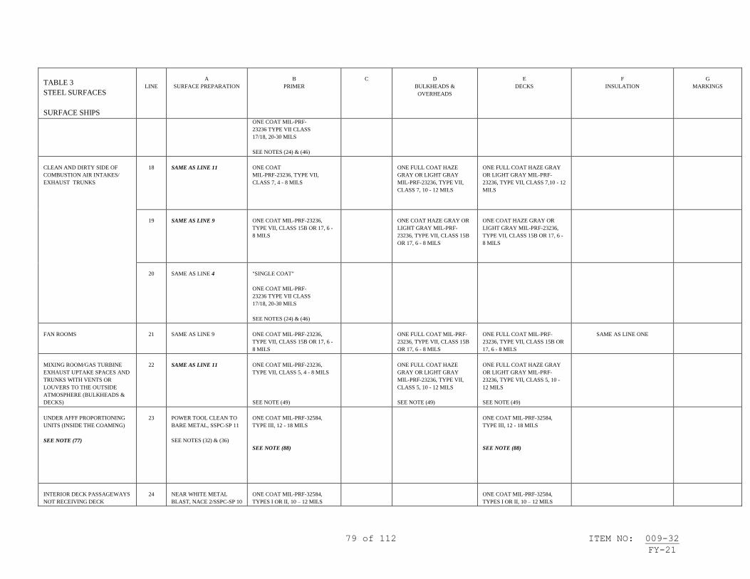
79 of 112 ITEM NO: 009-32
FY-21
TABLE 3
STEEL SURFACES
SURFACE SHIPS
LINE
A
SURFACE PREPARATION
B
PRIMER
C
D
BULKHEADS &
OVERHEADS
E
DECKS
F
INSULATION
G
MARKINGS
ONE COAT MIL-PRF-
23236 TYPE VII CLASS
17/18, 20-30 MILS
SEE NOTES (24) & (46)
CLEAN AND DIRTY SIDE OF
COMBUSTION AIR INTAKES/
EXHAUST TRUNKS
18
SAME AS LINE 11
ONE COAT
MIL-PRF-23236, TYPE VII,
CLASS 7, 4 - 8 MILS
ONE FULL COAT HAZE
GRAY OR LIGHT GRAY
MIL-PRF-23236, TYPE VII,
CLASS 7, 10 - 12 MILS
ONE FULL COAT HAZE GRAY
OR LIGHT GRAY MIL-PRF-
23236, TYPE VII, CLASS 7,10 - 12
MILS
19
SAME AS LINE 9
ONE COAT MIL-PRF-23236,
TYPE VII, CLASS 15B OR 17, 6 -
8 MILS
ONE COAT HAZE GRAY OR
LIGHT GRAY MIL-PRF-
23236, TYPE VII, CLASS 15B
OR 17, 6 - 8 MILS
ONE COAT HAZE GRAY OR
LIGHT GRAY MIL-PRF-23236,
TYPE VII, CLASS 15B OR 17, 6 -
8 MILS
20
SAME AS LINE 4
"SINGLE COAT"
ONE COAT MIL-PRF-
23236 TYPE VII CLASS
17/18, 20-30 MILS
SEE NOTES (24) & (46)
FAN ROOMS
21
SAME AS LINE 9
ONE COAT MIL-PRF-23236,
TYPE VII, CLASS 15B OR 17, 6 -
8 MILS
ONE FULL COAT MIL-PRF-
23236, TYPE VII, CLASS 15B
OR 17, 6 - 8 MILS
ONE FULL COAT MIL-PRF-
23236, TYPE VII, CLASS 15B OR
17, 6 - 8 MILS
SAME AS LINE ONE
MIXING ROOM/GAS TURBINE
EXHAUST UPTAKE SPACES AND
TRUNKS WITH VENTS OR
LOUVERS TO THE OUTSIDE
ATMOSPHERE (BULKHEADS &
DECKS)
22
SAME AS LINE 11
ONE COAT MIL-PRF-23236,
TYPE VII, CLASS 5, 4 - 8 MILS
SEE NOTE (49)
ONE FULL COAT HAZE
GRAY OR LIGHT GRAY
MIL-PRF-23236, TYPE VII,
CLASS 5, 10 - 12 MILS
SEE NOTE (49)
ONE FULL COAT HAZE GRAY
OR LIGHT GRAY MIL-PRF-
23236, TYPE VII, CLASS 5, 10 -
12 MILS
SEE NOTE (49)
UNDER AFFF PROPORTIONING
UNITS (INSIDE THE COAMING)
SEE NOTE (77)
23
POWER TOOL CLEAN TO
BARE METAL, SSPC-SP 11
SEE NOTES (32) & (36)
ONE COAT MIL-PRF-32584,
TYPE III, 12 - 18 MILS
SEE NOTE (88)
ONE COAT MIL-PRF-32584,
TYPE III, 12 - 18 MILS
SEE NOTE (88)
INTERIOR DECK PASSAGEWAYS
NOT RECEIVING DECK
24
NEAR WHITE METAL
BLAST, NACE 2/SSPC-SP 10
ONE COAT MIL-PRF-32584,
TYPES I OR II, 10 – 12 MILS
ONE COAT MIL-PRF-32584,
TYPES I OR II, 10 – 12 MILS

80 of 112 ITEM NO: 009-32
FY-21
TABLE 3
STEEL SURFACES
SURFACE SHIPS
LINE
A
SURFACE PREPARATION
B
PRIMER
C
D
BULKHEADS &
OVERHEADS
E
DECKS
F
INSULATION
G
MARKINGS
COVERINGS (HIGH DURABILITY
DECK PAINT)
SEE NOTE (12)
- OR -
POWER TOOL CLEAN TO
BARE METAL, SSPC-SP 11
SEE NOTE (88)
SEE NOTE (88)
INTERIOR STEEL SURFACES
25
SAME AS LINE 14
SAME AS LINE ONE
SAME AS LINE ONE
SAME AS LINE ONE
SAME AS LINE ONE
SAME AS LINE ONE
26
SAME AS LINE 16
SAME AS LINE ONE
SAME AS LINE ONE
SAME AS LINE ONE
SAME AS LINE ONE
SAME AS LINE ONE
27
SAME AS LINE 24
SAME AS LINE ONE
SAME AS LINE ONE
SAME AS LINE ONE
SAME AS LINE ONE
SAME AS LINE ONE

81 of 112 ITEM NO: 009-32
FY-21
TABLE 3
ALUMINUM
SURFACES
SURFACE SHIPS
LINE
A
SURFACE PREPARATION
B
PRIMER
C
D
BULKHEADS & OVERHEADS
E
DECKS
F
INSULATION
G
MARKINGS
INTERIOR COMPARTMENTS
SEE NOTE (17)
28
POWER TOOL CLEAN TO
BARE METAL, SSPC-SP 11,
SEE NOTES (28) & (90)
2 COATS FORMULA 84,
TT-P-645, ALKYD,
2 - 4 MILS/COAT
- OR -
ONE COAT MIL-PRF-23236,
TYPE V VI, OR VII, CLASS 5 OR
7, 4 - 8 MILS
--OR--
ONE COAT MIL-PRF-32584,
TYPES I OR II, 10 – 12 MILS
SEE NOTE (88)
2 COATS MIL-DTL-24607,
2 - 4 MILS/COAT
- OR -
2 COATS MIL-PRF-24596, WATER-
BASED INTERIOR LATEX, 2 - 4
MILS/COAT
SEE NOTE (9)
TO DECKS NOT
RECEIVING COVERING:
ONE COAT MIL-PRF-32584,
TYPES I OR II, 10 – 12 MILS
SEE NOTE (88)
HULL, VENTILATION & PIPING
INSULATION
ONE COAT MIL-DTL-24607,
2 - 4 MILS
- OR -
ONE COAT MIL-PRF-24596,
WATER-BASED INTERIOR
LATEX, 2 - 4 MILS
IF REQUIRED FOR HIDING, ONE
ADDITIONAL COAT MUST BE
APPLIED.
SEE NOTES (9), (28) & (41)
FOR COMPARTMENT
PIPING &
VENTILATION
SEE NOTE (18)
29
HAND TOOL CLEANING,
SSPC-SP 2
SEE NOTES (28) & (90)
SAME AS LINE 28
SAME AS LINE 28
SAME AS LINE 28
SAME AS LINE 28
SAME AS LINE 28
INTERIOR COMPARTMENTS
(OVERCOAT)
SEE NOTE (17)
30
SAME AS LINE 29
SAME AS LINE 26 FOR BARE
METAL AREAS
SAME AS LINE 28
EXCEPT ONE COAT
SAME AS LINE 28
SAME AS LINE 28
SAME AS LINE 28
31
POWER TOOL CLEANING,
SSPC-SP 3
SEE NOTES (28) & (90)
SAME AS LINE 26 FOR BARE
METAL AREAS
SAME AS LINE 28
EXCEPT ONE COAT
SAME AS LINE 28
SAME AS LINE 28
SAME AS LINE 28
WELDING BAYS AND
LIGHT TRAPS
32
SAME AS LINE 28
SAME AS LINE 28
ONE COAT BLACK, LOW GLOSS
MIL-PRF-23236, TYPE V, VI, OR VII,
4 - 8 MILS
ONE COAT BLACK, SEMI-
GLOSS MIL-PRF-23236,
TYPE V, VI, OR VII, 4 - 8
MILS
- OR -
ONE COAT MIL-PRF-32584,
TYPES I OR II, 10 – 12 MILS
SEE NOTE (88)
33
SAME AS LINE 29
SAME AS LINE 28
SAME AS LINE 32
SAME AS LINE 32

82 of 112 ITEM NO: 009-32
FY-21
TABLE 3
ALUMINUM
SURFACES
SURFACE SHIPS
LINE
A
SURFACE PREPARATION
B
PRIMER
C
D
BULKHEADS & OVERHEADS
E
DECKS
F
INSULATION
G
MARKINGS
WET SPACES (WASH
ROOMS, WATER CLOSETS,
SHOWER STALLS,
GALLEYS, SCULLERIES, &
STOREROOMS WHERE
HEAVY CONDENSATION IS
COMMON)
34
POWER TOOL CLEAN TO
BARE METAL, SSPC-SP 11
(DECKS)
POWER TOOL CLEANING,
SSPC-SP 3 (BULKHEADS/
OVERHEADS)
SEE NOTE (28) & (90)
"SINGLE COAT"
ONE COAT MIL-PRF-
23236 TYPE VII CLASS
17/18, 20-30 MILS
SEE NOTES (24) & (46)
SAME AS LINE 28
SAME AS LINE 28
35
SAME AS LINE 34
ONE COAT MIL-PRF-23236,
TYPE VII, CLASS 15B OR 17, 6 -
8 MILS
--OR--
ONE COAT MIL-PRF-32584,
TYPE II, 10 – 12 MILS
SEE NOTE (88)
TO DECKS NOT
RECEIVING COVERING:
ONE COAT MIL-PRF-32584,
TYPE II, 10 – 12 MILS
SEE NOTE (88)
SAME AS LINE 28
SAME AS LINE 28
MACHINERY SPACES &
BILGES
36
POWER TOOL CLEAN TO
BARE METAL, SSPC-SP 11
- OR -
WATERJETTING TO
NACE/SSPC-SP WJ-2
- OR -
NEAR WHITE METAL
BLAST, NACE 2/SSPC-SP 10
USING GARNET,
ALUMINUM OXIDE, OR
CRUSHED GLASS
SEE NOTES (28), (78), (89),
(90), & (91)
ONE COAT MIL-PRF-23236,
TYPE VII, CLASS 17, 6 - 8 MILS
ABOVE BILGE AREA:
2 COATS F-124, MIL-DTL-24607, 2 -
4 MILS/COAT
BILGE AREA:
ONE FULL COAT MIL-PRF-
23236, TYPE VII, CLASS 17,
6 - 8 MILS
SAME AS LINE 28
37
SAME AS LINE 36
ONE COAT MIL-PRF-23236,
TYPE VII, CLASS 15B, 6 - 8 MILS
SAME AS LINE 36
BILGE AREA:
ONE FULL COAT MIL-PRF-
23236, TYPE VII, CLASS
15B, 6 - 8 MILS
SEE NOTE (4)
SAME AS LINE 28
38
NEAR WHITE METAL
BLAST, NACE 2/SSPC-SP 10
USING GARNET,
ALUMINUM OXIDE, OR
CRUSHED GLASS
SEE NOTES (28), (78), & (89)
ONE COAT MIL-PRF-23236,
TYPE VII, CLASS 5, 4 - 8 MILS
SEE NOTE (49)
SAME AS LINE 36
BILGE AREA:
ONE FULL COAT MIL-PRF-
23236, TYPE VII, CLASS 5,
10 - 12 MILS
SEE NOTES (4) & (49)
SAME AS LINE 28

83 of 112 ITEM NO: 009-32
FY-21
TABLE 3
ALUMINUM
SURFACES
SURFACE SHIPS
LINE
A
SURFACE PREPARATION
B
PRIMER
C
D
BULKHEADS & OVERHEADS
E
DECKS
F
INSULATION
G
MARKINGS
39
SAME AS LINE 38
"SINGLE COAT"
ONE COAT MIL-PRF-23236
TYPE VII CLASS 5/18, 20-30
MILS
SEE NOTES (24) & (46)
SAME AS LINE 36
SAME AS LINE 28
40
SAME AS LINE 36
"SINGLE COAT"
ONE COAT MIL-PRF-23236
TYPE VII CLASS 17/18, 20-30
MILS
SEE NOTES (24) & (46)
SAME AS LINE 36
SAME AS LINE 28
VENT PLENUMS
41
SAME AS LINE 38
ONE COAT MIL-PRF-23236,
TYPE VII, CLASS 5,
4 - 8 MILS
SEE NOTE (49)
ONE FULL COAT HAZE GRAY OR
LIGHT GRAY MIL-PRF-23236, TYPE
VII, CLASS 5, 10 - 12 MILS
SEE NOTE (49)
ONE FULL COAT HAZE
GRAY OR LIGHT GRAY
MIL-PRF-23236, TYPE VII,
CLASS 5, 10 - 12 MILS
SEE NOTE (49)
TWO COATS MIL-PRF-24596
GRADE A WATER BASED
LATEX, GRAY, AS REQUIRED
FOR HIDING (OVER INSTALLED
INSULATION)
42
SAME AS LINE 38
"SINGLE COAT"
ONE COAT MIL-PRF-23236
TYPE VII CLASS 5/18, 20-30
MILS
SEE NOTES (24) & (46)
SAME AS LINE 41
43
WATERJETTING TO
NACE/SSPC-SP WJ-2
- OR -
NEAR WHITE METAL
BLAST, NACE 2/SSPC-SP 10
USING GARNET,
ALUMINUM OXIDE, OR
CRUSHED GLASS
SEE NOTES (89) & (91)
ONE COAT MIL-PRF-23236,
TYPE VII, CLASS 17,
6 - 8 MILS
ONE FULL COAT HAZE GRAY OR
LIGHT GRAY MIL-PRF-23236, TYPE
VII, CLASS 17, 6 - 8 MILS
ONE FULL COAT HAZE
GRAY OR LIGHT GRAY
MIL-PRF-23236, TYPE VII,
CLASS 17, 6 - 8 MILS
SAME AS LINE 41
44
SAME AS LINE 43
ONE COAT MIL-PRF-23236,
TYPE VII, CLASS 15B,
6 - 8 MILS
ONE FULL COAT HAZE GRAY OR
LIGHT GRAY MIL-PRF-23236, TYPE
VII, CLASS 15B, 6 - 8 MILS
ONE FULL COAT HAZE
GRAY OR LIGHT GRAY
MIL-PRF-23236, TYPE VII,
CLASS 15B, 6 - 8 MILS
SAME AS LINE 41

84 of 112 ITEM NO: 009-32
FY-21
TABLE 3
ALUMINUM
SURFACES
SURFACE SHIPS
LINE
A
SURFACE PREPARATION
B
PRIMER
C
D
BULKHEADS & OVERHEADS
E
DECKS
F
INSULATION
G
MARKINGS
45
SAME AS LINE 43
"SINGLE COAT"
ONE COAT MIL-PRF-
23236 TYPE VII CLASS
17/18, 20-30 MILS
SEE NOTES (24) & (46)
SAME AS LINE 41
CLEAN AND DIRTY SIDE OF
COMBUSTION AIR
INTAKES/EXHAUST
TRUNKS
SEE NOTE (66)
46
SAME AS LINE 38
ONE COAT MIL-PRF-23236,
TYPE VII, CLASS 7,
4 - 8 MILS
ONE FULL COAT HAZE
GRAY OR LIGHT GRAY
MIL-PRF-23236, TYPE VII,
CLASS 7, 10 - 12 MILS
47
SAME AS LINE 36
ONE COAT MIL-PRF-23236,
TYPE VII, CLASS 17
6 - 8 MILS
ONE FULL COAT HAZE
GRAY OR LIGHT GRAY
MIL-PRF-23236, TYPE VII,
CLASS 17, 6 - 8 MILS
48
SAME AS LINE 36
ONE COAT MIL-PRF-23236,
TYPE VII, CLASS 15B,
6 - 8 MILS
ONE FULL COAT HAZE
GRAY OR LIGHT GRAY
MIL-PRF-23236, TYPE VII,
CLASS 15B, 6 - 8 MILS
49
SAME AS LINE 36
"SINGLE COAT"
ONE COAT MIL-PRF-
23236 TYPE VII CLASS
17/18, 20-30 MILS
SEE NOTES (24) & (46)
FAN ROOMS
50
SAME AS LINE 36
ONE COAT MIL-PRF-23236,
TYPE VII, CLASS 15B OR 17, 6 -
8 MILS
ONE FULL COAT MIL-PRF-23236,
TYPE VII, CLASS 15B OR 17, 6 - 8
MILS
ONE FULL COAT MIL-PRF-
23236, TYPE VII, CLASS
15B OR 17, 6 - 8 MILS
SAME AS LINE 28
MIXING ROOM//GAS
TURBINE EXHAUST
UPTAKE SPACES AND
TRUNKS WITH VENTS OR
LOUVERS TO THE OUTSIDE
ATMOSPHERE
(BULKHEADS & DECKS)
51
SAME AS LINE 38
ONE COAT MIL-PRF-23236,
TYPE VII, CLASS 5,
4 - 8 MILS
SEE NOTE (49)
ONE FULL COAT MIL-PRF-23236,
TYPE VII, CLASS 5, 10 - 12 MILS
SEE NOTE (49)
ONE FULL COAT HAZE
GRAY OR LIGHT GRAY
MIL-PRF-23236, TYPE VII,
CLASS 5, 10 - 12 MILS
SEE NOTE (49)
INTERIOR ALUMINUM
SURFACES
52
SAME AS LINE 28
SAME AS LINE 28
SAME AS LINE 28
SAME AS LINE 28
SAME AS LINE 28
SAME AS LINE 28
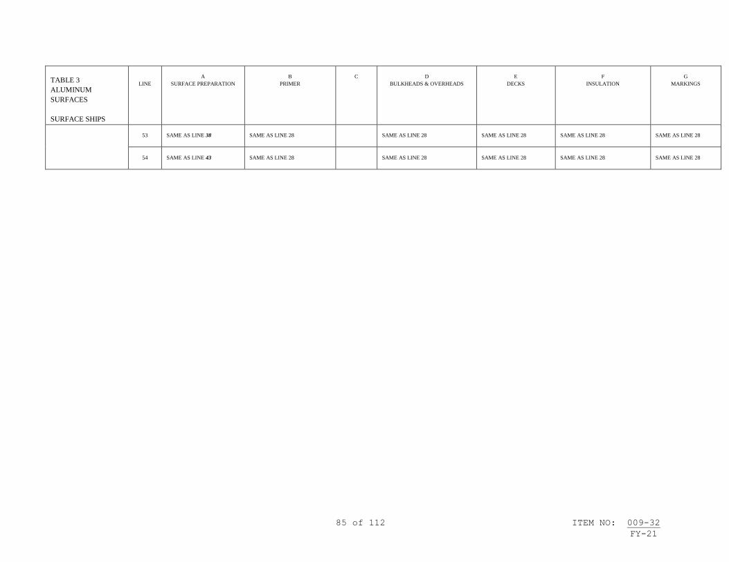
85 of 112 ITEM NO: 009-32
FY-21
TABLE 3
ALUMINUM
SURFACES
SURFACE SHIPS
LINE
A
SURFACE PREPARATION
B
PRIMER
C
D
BULKHEADS & OVERHEADS
E
DECKS
F
INSULATION
G
MARKINGS
53
SAME AS LINE 38
SAME AS LINE 28
SAME AS LINE 28
SAME AS LINE 28
SAME AS LINE 28
SAME AS LINE 28
54
SAME AS LINE 43
SAME AS LINE 28
SAME AS LINE 28
SAME AS LINE 28
SAME AS LINE 28
SAME AS LINE 28
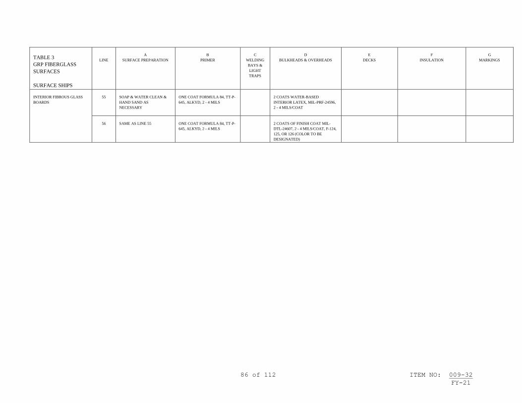
86 of 112 ITEM NO: 009-32
FY-21
TABLE 3
GRP FIBERGLASS
SURFACES
SURFACE SHIPS
LINE
A
SURFACE PREPARATION
B
PRIMER
C
WELDING
BAYS &
LIGHT
TRAPS
D
BULKHEADS & OVERHEADS
E
DECKS
F
INSULATION
G
MARKINGS
INTERIOR FIBROUS GLASS
BOARDS
55
SOAP & WATER CLEAN &
HAND SAND AS
NECESSARY
ONE COAT FORMULA 84, TT-P-
645, ALKYD, 2 - 4 MILS
2 COATS WATER-BASED
INTERIOR LATEX, MIL-PRF-24596,
2 - 4 MILS/COAT
56
SAME AS LINE 55
ONE COAT FORMULA 84, TT-P-
645, ALKYD, 2 - 4 MILS
2 COATS OF FINISH COAT MIL-
DTL-24607, 2 - 4 MILS/COAT, F-124,
125, OR 126 (COLOR TO BE
DESIGNATED)
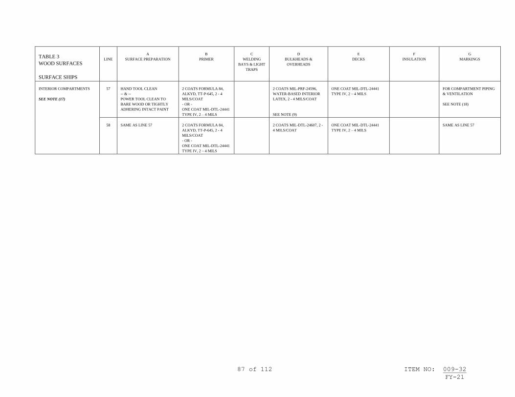
87 of 112 ITEM NO: 009-32
FY-21
TABLE 3
WOOD SURFACES
SURFACE SHIPS
LINE
A
SURFACE PREPARATION
B
PRIMER
C
WELDING
BAYS & LIGHT
TRAPS
D
BULKHEADS &
OVERHEADS
E
DECKS
F
INSULATION
G
MARKINGS
INTERIOR COMPARTMENTS
SEE NOTE (17)
57
HAND TOOL CLEAN
-- & --
POWER TOOL CLEAN TO
BARE WOOD OR TIGHTLY
ADHERING INTACT PAINT
2 COATS FORMULA 84,
ALKYD, TT-P-645, 2 - 4
MILS/COAT
- OR -
ONE COAT MIL-DTL-24441
TYPE IV, 2 – 4 MILS
2 COATS MIL-PRF-24596,
WATER-BASED INTERIOR
LATEX, 2 - 4 MILS/COAT
SEE NOTE (9)
ONE COAT MIL-DTL-24441
TYPE IV, 2 – 4 MILS
FOR COMPARTMENT PIPING
& VENTILATION
SEE NOTE (18)
58
SAME AS LINE 57
2 COATS FORMULA 84,
ALKYD, TT-P-645, 2 - 4
MILS/COAT
- OR -
ONE COAT MIL-DTL-24441
TYPE IV, 2 – 4 MILS
2 COATS MIL-DTL-24607, 2 -
4 MILS/COAT
ONE COAT MIL-DTL-24441
TYPE IV, 2 – 4 MILS
SAME AS LINE 57

88 of 112 ITEM NO: 009-32 FY-21
TABLE 4
STEEL SURFACES
SURFACE SHIPS
LINE
A
SURFACE PREPARATION
B
C
D
E
F
G
TOTAL SYSTEM
SEE NOTE (53)
AIRCRAFT CARRIER
POTABLE WATER TANKS
SEE NOTE (26)
1
NEAR WHITE METAL
BLAST, NACE 2/SSPC-SP
10
ONE COAT F-150,
MIL-DTL-24441, TYPE III,
2 - 4 MILS
ONE STRIPE COAT
MIL-DTL-24441, TYPE III,
2 - 4 MILS
ONE COAT MIL-DTL-24441,
TYPE III, 2 - 4 MILS
ONE STRIPE COAT
MIL-DTL-24441,
TYPE III, 2 - 4 MILS
ONE COAT MIL-DTL-
24441, TYPE III, 2 - 4
MILS
AT ADEQUATE
THICKNESS TO MEET
COATING RANGE
TOTAL SYSTEM 8 MILS MIN,
12 MILS MAX (AREAS
WITHOUT STRIPE COAT)
SEE NOTE (37)
2
SAME AS LINE ONE
ONE COAT MIL-PRF-23236,
TYPE VII, CLASS 9,
4 - 8 MILS
SEE NOTES (55), (58), & (73)
ONE COAT MIL-PRF-23236,
TYPE VII, CLASS 9, 10 - 12
MILS WHITE OR OFF-WHITE
SEE NOTES (55) & (73)
3
SAME AS LINE ONE
"SINGLE COAT"
ONE COAT MIL-PRF-23236
TYPE VII CLASS 9/18, 20-30
MILS WHITE OR OFF-WHITE
SEE NOTES (24), (55), & (58)
NON-AIRCRAFT CARRIER
POTABLE WATER TANKS
SEE NOTES (26) & (54)
4
SAME AS LINE ONE
ONE COAT MIL-PRF-23236,
TYPE VII, CLASS 9,
4 - 8 MILS
SEE NOTES (55) & (58)
ONE COAT MIL-PRF-23236,
TYPE VII, CLASS 9, 10 - 12
MILS WHITE OR OFF-WHITE
SEE NOTE (55)
5
SAME AS LINE ONE
"SINGLE COAT"
ONE COAT MIL-PRF-23236
TYPE VII CLASS 9/18, 20-30
MILS WHITE OR OFF-WHITE
SEE NOTES (24), (55), & (58)
AIRCRAFT CARRIER
RESERVE FEEDWATER
TANKS AND FRESH WATER
DRAIN COLLECTING TANKS
SEE NOTE (26)
6
SAME AS LINE ONE
ONE COAT F-150,
MIL-DTL-24441, TYPE III,
2 - 4 MILS
ONE STRIPE COAT
MIL-DTL-24441, TYPE III,
2 - 4 MILS
ONE COAT MIL-DTL-24441,
TYPE III, 2 - 4 MILS
ONE STRIPE COAT
MIL-DTL-24441,
TYPE III, 2 - 4 MILS
ONE COAT MIL-DTL-
24441, TYPE III, 2 - 4
MILS
AT ADEQUATE
THICKNESS TO MEET
COATING RANGE
TOTAL SYSTEM 8 MILS MIN,
12 MILS MAX
(AREAS WITHOUT STRIPE
COAT)
NON-AIRCRAFT CARRIER
RESERVE FEEDWATER
TANKS AND FRESHWATER
DRAIN COLLECTING TANKS
SEE NOTES (26) & (54)
7
SAME AS LINE ONE
ONE COAT F-150,
MIL-DTL-24441, TYPE III,
2 - 4 MILS
ONE STRIPE COAT
MIL-DTL-24441, TYPE III,
2 - 4 MILS
ONE COAT MIL-DTL-24441,
TYPE III, 2 - 4 MILS
ONE STRIPE COAT
MIL-DTL-24441,
TYPE III, 2 - 4 MILS
ONE COAT MIL-DTL-
24441, TYPE III, 2 - 4
MILS
AT ADEQUATE
THICKNESS TO MEET
COATING RANGE
TOTAL SYSTEM 8 MILS MIN,
12 MILS MAX
(AREAS WITHOUT STRIPE
COAT)

89 of 112 ITEM NO: 009-32 FY-21
TABLE 4
STEEL SURFACES
SURFACE SHIPS
LINE
A
SURFACE PREPARATION
B
C
D
E
F
G
TOTAL SYSTEM
SEE NOTE (53)
8
SAME AS LINE ONE
ONE COAT MIL-PRF-23236,
TYPE VII, CLASS 11,
4 - 8 MILS
SEE NOTES (55) & (58)
ONE COAT MIL-PRF-23236,
TYPE VII, CLASS 11,
4 - 8 MILS
SEE NOTE (55)
9
SAME AS LINE ONE
"SINGLE COAT"
ONE COAT MIL-PRF-23236
TYPE VII CLASS 11/18, 20-30
MILS
SEE NOTES (24), (46), (55), &
(58)
JET PROPULSION FUEL (JP-5)
TANKS, MOGAS TANKS,
CONTAMINATED FUEL
TANKS, DDG 51 CLASS FUEL
SERVICE TANKS, FUEL
STORAGE COMP TANKS,
SUMPS, DIRTY DRAIN
COLLECTING TANKS, BILGE
& OILY WASTE TANKS
15-20 YEARS SERVICE LIFE
SEE NOTES (26) & (65)
10
SAME AS LINE ONE
ONE COAT MIL-PRF-23236,
TYPE VII, CLASS 5,
4 - 8 MILS
SEE NOTES (49) & (58)
ONE COAT MIL-PRF-23236,
TYPE VII, CLASS 5,
10 - 12 MILS
SEE NOTE (49)
11
SAME AS LINE ONE
"SINGLE COAT"
ONE COAT MIL-PRF-23236
TYPE VII CLASS 5/18, 20-30
MILS
SEE NOTES (24), (46), & (58)
JP-5 TANKS, MOGAS TANKS,
CONTAMINATED FUEL
TANKS, DDG 51 CLASS FUEL
SERVICE TANKS, FUEL
STORAGE COMP TANKS,
SUMPS, DIRTY DRAIN
COLLECTING TANKS, BILGE
& OILY WASTE TANKS
10-12 YEARS SERVICE LIFE
SEE NOTES (65) & (38)
12
SAME AS LINE ONE
SAME AS LINE 10
SAME AS LINE 10
13
SAME AS LINE ONE
"SINGLE COAT"
ONE COAT MIL-PRF-23236
TYPE VII CLASS 5/18, 20-30
MILS
SEE NOTES (24), (46), & (58)

90 of 112 ITEM NO: 009-32 FY-21
TABLE 4
STEEL SURFACES
SURFACE SHIPS
LINE
A
SURFACE PREPARATION
B
C
D
E
F
G
TOTAL SYSTEM
SEE NOTE (53)
AIRCRAFT CARRIER JP-5
TANKS, CONTAMINATED
FUEL TANKS, DIRTY DRAIN
COLLECTING TANKS, BILGE
& OILY WASTE TANKS,
FLOODABLE VOIDS, AND
NON-FLOODABLE VOIDS
(USE ONLY WHEN
SUBSTRATE TEMPERATURE
CANNOT BE MAINTAINED
ABOVE 50 DEGREES
FAHRENHEIT)
SEE NOTE (26)
14
SAME AS LINE ONE
ONE COAT MIL-PRF-23236,
TYPE V OR VI, CLASS 5,
GRADE A OR B, 4 - 8 MILS
SEE NOTE (84)
ONE STRIPE COAT MIL-
PRF-23236, TYPE V OR VI
CLASS 5, GRADE A OR B, 4
- 8 MILS
SEE NOTE (84)
ONE COAT MIL-PRF-23236,
TYPE V OR VI CLASS 5,
GRADE A OR B, 4 - 8 MILS
SEE NOTE (84)
COLLECTION, HOLDING AND
TRANSFER (CHT), VACUUM
COLLECTION (VC) / MARINE
SANITATION DEVICE (MSD)/
LAUNDRY DRAIN
COLLECTION TANKS
SEE NOTE (26)
15
SAME AS LINE ONE
ONE COAT MIL-PRF-23236,
TYPE VII, CLASS 13, 4 - 8
MILS
SEE NOTE (58)
ONE COAT MIL-PRF-23236,
TYPE VII, CLASS 13, 10 - 12
MILS
16
SAME AS LINE ONE
"SINGLE COAT"
ONE COAT MIL-PRF-23236,
TYPE VII CLASS 13/18, 20-30
MILS
SEE NOTES (24), (46), & (58)
BALLAST TANKS,
FLOODABLE VOIDS
(SUBSTRATE TEMPERATURE
50 DEGREES FAHRENHEIT &
ABOVE)
EDGE RETENTIVE-
EXTENDED SERVICE LIFE 15-
20 YEARS (MORE STRINGENT
HUMIDITY REQUIREMENTS)
SEE NOTE (26)
17
SAME AS LINE ONE
"SINGLE COAT"
ONE COAT MIL-PRF-23236
TYPE VII CLASS 7/18, 20-30
MILS
SEE NOTES (24), (46), & (58)

91 of 112 ITEM NO: 009-32 FY-21
TABLE 4
STEEL SURFACES
SURFACE SHIPS
LINE
A
SURFACE PREPARATION
B
C
D
E
F
G
TOTAL SYSTEM
SEE NOTE (53)
BALLAST TANKS,
FLOODABLE VOIDS
(SUBSTRATE TEMPERATURE
50 DEGREES FAHRENHEIT &
ABOVE)
EDGE RETENTIVE SERVICE
LIFE 10 - 12 YEARS (LESS
STRINGENT HUMIDITY
REQUIREMENTS)
SEE NOTE (38)
18
SAME AS LINE ONE
"SINGLE COAT"
ONE COAT MIL-PRF-23236
TYPE VII CLASS 7/18, 20-30
MILS
SEE NOTES (24), (46), & (58)
BALLAST TANKS,
FLOODABLE VOIDS (USE
ONLY WHEN SUBSTRATE
TEMPERATURE CANNOT BE
MAINTAINED ABOVE 50
DEGREES FAHRENHEIT)
NORMAL 5 - 7 YEARS
SERVICE LIFE
SEE NOTE (26)
19
SAME AS LINE ONE
ONE COAT MIL-PRF-23236,
TYPE V OR VI CLASS 5 OR 7,
GRADE A OR B, 4 - 8 MILS
SEE NOTES (8) & (84)
ONE STRIPE COAT MIL-
PRF-23236, TYPE V OR VI
CLASS 5 OR 7, GRADE A
OR B, 4 - 8 MILS
SEE NOTES (8) & (84)
ONE COAT MIL-PRF-23236,
TYPE V OR VI CLASS 5 OR 7,
GRADE A OR B, 4 - 8 MILS
SEE NOTES (8) & (84)
PEAK TANKS
EDGE RETENTIVE-
EXTENDED SERVICE LIFE 15-
20 YEARS (MORE STRINGENT
HUMIDITY REQUIREMENTS)
SEE NOTE (26)
20
SAME AS LINE ONE
ONE COAT MIL-PRF-23236,
TYPE VII CLASS 7, 4 - 8
MILS
SEE NOTE (58)
ONE COAT MIL-PRF-23236,
TYPE VII CLASS 7, 10 - 12
MILS
21
SAME AS LINE ONE
SAME AS LINE 18
PEAK TANKS
EDGE RETENTIVE SERVICE
LIFE 10 - 12 YEARS (LESS
STRINGENT HUMIDITY
REQUIREMENTS)
22
SAME AS LINE ONE
SAME AS LINE 20
SAME AS LINE 20
SEE NOTE (38)
23
SAME AS LINE ONE
SAME AS LINE 18

92 of 112 ITEM NO: 009-32 FY-21
TABLE 4
STEEL SURFACES
SURFACE SHIPS
LINE
A
SURFACE PREPARATION
B
C
D
E
F
G
TOTAL SYSTEM
SEE NOTE (53)
CHAIN LOCKERS AND NON-
FLOODABLE VOIDS
SEE NOTE (38)
24
SAME AS LINE ONE
"SINGLE COAT"
ONE COAT MIL-PRF-23236,
TYPE VII, CLASS 7/18, 20-30
MILS
SEE NOTES (24), (46), & (58)
25
SAME AS LINE ONE
ONE COAT MIL-PRF-23236,
TYPE VII, CLASS 5 OR 7,
GRADE A OR B, 4 - 8 MILS
SEE NOTES (8), (58) & (84)
ONE COAT MIL-PRF-23236,
TYPE VII CLASS 5 OR 7,
GRADE A OR B, 4 - 8 MILS
SEE NOTES (8), (58), & (84)
CVN CATAPULT WATER
BRAKE TANKS
26
SAME AS LINE ONE
ONE COAT INORGANIC
ZINC SILICATE TYPE
COATING 2-4 MILS
SEE NOTE (51)

93 of 112 ITEM NO: 009-32 FY-21
TABLE 4
ALUMINUM SURFACES
SURFACE SHIPS
LINE
A
SURFACE PREPARATION
B
C
D
E
F
G
TOTAL SYSTEM
SEE NOTE (53)
TANKS AND VOIDS
27
NEAR WHITE METAL
BLAST, NACE 2/SSPC-SP
10 USING GARNET,
ALUMINUM OXIDE, OR
CRUSHED GLASS
SEE NOTE (89)
SAME AS STEEL FOR
SPECIFIED SERVICE
SAME AS STEEL FOR
SPECIFIED SERVICE
SAME AS STEEL FOR
SPECIFIED SERVICE
SAME AS STEEL FOR
SPECIFIED SERVICE
SAME AS STEEL FOR
SPECIFIED SERVICE
SAME AS STEEL FOR
SPECIFIED SERVICE
LCS 2 CLASS FUEL SERVICE
AND STORAGE TANKS
SEE NOTE (26)
28
SAME AS LINE 27
ONE COAT MIL-PRF-
23236, TYPE VII, CLASS 5,
4 - 8 MILS
SEE NOTES (49) & (58)
ONE COAT MIL-PRF-23236,
TYPE VII, CLASS 5,
10 - 12 MILS
SEE NOTE (49)
29
SAME AS LINE 27
"SINGLE COAT"
ONE COAT MIL-PRF-23236
TYPE VII CLASS 5/18, 20-30
MILS
SEE NOTES (24), (46), &
(58)

94 of 112 ITEM NO: 009-32 FY-21
TABLE 5
VARIOUS LOCATIONS
SURFACE SHIPS
LINE
A
SURFACE PREPARATION
B
C
D
E
F
TOTAL SYSTEM
SEE NOTE (53)
G
DESIGNATIONS &
MARKINGS
UNHEATED PIPING, FITTINGS,
VALVES
1
HAND TOOL CLEAN,
SSPC-SP 2
2 COATS F-84, ALKYD, TT-
P-645,
2 - 4 MILS/COAT
2 COATS OF BILGE FINISH
COAT TO MATCH
SURROUNDING SURFACES,
INCLUDING LAGGED
SURFACES
ONE COAT
MIL-PRF-24635,
5 - 8 MILS, FOR COLOR
CODED SYSTEMS
MACHINERY, GAUGEBOARDS;
UNHEATED FERROUS MACHINERY
EXTERNAL SURFACES
2
POWER TOOL CLEAN,
SSPC-SP 3
SAME AS LINE ONE
ONE COAT F-111,
MIL-DTL-15090, 2 - 4 MILS
- OR -
ONE COAT GRAY MIL-
PRF-24635, TYPE V,
5 - 8 MILS
SEE NOTE (86)
IF REQUIRED FOR HIDING,
ONE ADDITIONAL COAT: F-
111,
MIL-DTL-15090, 2 - 4 MILS
- OR -
MIL-PRF-24635, TYPE V, 5 - 8
MILS
SEE NOTE (86)
UNINSULATED SIDE OF BULKHEAD
OR SHELL ADJACENT TO SEA OR
AC BOUNDARY (FOR INTERIOR
COMPARTMENTS ONLY)
3
POWER TOOL CLEAN TO
BARE METAL, SSPC-SP 11
ONE COAT HEMPEL
HEMPADUR 45880,
4 - 6 MILS
ONE COAT HEMPEL
ANTI-CONDENS
617US-10000, 50 - 60 MILS
4
SAME AS LINE 3
ONE COAT F-84, ALKYD,
TT-P-645,
2 - 4 MILS
- OR -
ONE COAT MIL-PRF-23236,
TYPE V, VI, OR VII, CLASS
5 OR 7, 4 - 8 MILS
ONE COAT TEMP-COAT
101, 20 - 22 MILS
- OR -
ONE COAT SHERWIN-
WILLIAMS HEAT FLEX
3500, 20 – 22 MILS
- OR -
ONE COAT MASCOAT
DELTA-T MARINE, 20-22
MILS
ONE COAT TEMP-COAT 101,
20 - 22 MILS
- OR -
ONE COAT SHERWIN-
WILLIAMS HEAT FLEX 3500,
20 – 22 MILS
- OR -
ONE COAT MASCOAT
DELTA-T MARINE, 20-22
MILS
ONE COAT TEMP-COAT
101, 20 - 22 MILS
- OR -
ONE COAT SHERWIN-
WILLIAMS HEAT FLEX
3500, 20 – 22 MILS
- OR -
ONE COAT MASCOAT
DELTA-T MARINE, 20-22
MILS
5
SAME AS LINE 3
SAME AS LINE 4
ONE COAT KEFA AIRLESS
8125, 50 - 60 MILS
BOILERS & ECONOMIZERS (EXCEPT
PARTS USED FOR HEAT
TRANSFER), MACHINERY CASINGS,
FERROUS SHEET METAL
6
SAME AS LINE 3
ONE COAT PSX 892HS, 2 -
3 MILS
SEE NOTE (39)
7
SAME AS LINE 3
2 COATS OF TT-P-28
SUFFICIENT TO COVER
THE PROFILE

95 of 112 ITEM NO: 009-32 FY-21
TABLE 5
VARIOUS LOCATIONS
SURFACE SHIPS
LINE
A
SURFACE PREPARATION
B
C
D
E
F
TOTAL SYSTEM
SEE NOTE (53)
G
DESIGNATIONS &
MARKINGS
STEAM, RESERVE FEEDWATER,
BOTTOM/ SURFACE BLOW &
BOILER PRESSURE VESSEL PIPING
IN PREPARATION FOR
ULTRASONIC MEASUREMENTS
8
POWER TOOL CLEAN TO
BARE METAL, SSPC-SP 11,
USING STAINLESS STEEL
WIRE BRUSHES,
STAINLESS STEEL PADS,
OR ABRASIVE SANDING
DISCS (ANSI/BHMA
B74.18)
ELECTRICAL EQUIPMENT,
ELECTRONIC EQUIPMENT
9
SAME AS LINE ONE
2 COATS F-84, TT-P-645,
ALKYD, 2 - 4 MILS/COAT
2 COATS F-111, MIL-DTL-
15090, 2 - 4 MILS/COAT
CABLE, INTERIOR
10
SAME AS LINE ONE
2 COATS WATER-BASED
LATEX PER MIL-PRF-
24596, 2 - 4 MILS/COAT
2 COATS MIL-DTL-24607
2 - 4 MILS/COAT (FOR
COLOR MATCH IF
REQUIRED)
CABLE, EXTERIOR (OTHER THAN
POLYVINYL CHLORIDE (PVC), LOW
SMOKE)
11
SAME AS LINE ONE
SAME AS LINE 10
2 COATS MIL-PRF-24763,
TYPE II, CLASS 2, 2 – 4
MILS/COAT
--OR—
ONE COAT MIL-PRF-24635,
TYPE V TO MATCH
SURROUNDING AREA,
5 - 8 MILS
SEE NOTE (86)
ANCHOR (SURFACE SHIP BOW
ANCHORS)
FOR ANCHORS BELOW LOWER
BOOTTOPPING LIMIT, SEE NOTE
(13)
12
NEAR WHITE METAL
BLAST, NACE 2/SSPC-SP 10
SEE NOTES (14) & (21)
ONE COAT MIL-PRF-23236,
TYPE V OR VI, CLASS 5 OR
7, 4 - 8 MILS
- OR -
ONE COAT MIL-PRF-23236,
CLASS 5 OR 7, TYPE VII, 4
- 8 MILS
ONE COAT MIL-PRF-23236,
TYPE V OR VI, CLASS 5 OR
7, 4 - 8 MILS
- OR -
ONE COAT MIL-PRF-23236,
TYPE VII, CLASS 5 OR 7, 10
- 12 MILS
ONE COAT HAZE GRAY,
MIL-PRF-24635 TYPE V OR
VI, CLASS 2, GRADE B OR C,
5 - 8 MILS
SEE NOTES (85) & (86)
ANCHOR CHAIN, STERN GATE
CHAIN
SEE NOTE (15)
13
COMMERCIAL BLAST
CLEAN, NACE 3/SSPC-SP 6
SEE NOTES (14) & (21)
ONE COAT MIL-PRF-24635,
TYPE V OR VI, CLASS 1,
GRADE A, B OR C, 5 – 8
MILS
--OR--
ONE COAT MIL-PRF-23236
TYPE VI OR VII, 4-8 MILS
ONE COAT MIL-PRF-24635,
TYPE VI, CLASS 1, GRADE
A, 5 - 8 MILS
MIL-PRF-24635, TYPE VI,
CLASS 1, 5 – 8 MILS
INTERIOR GALVANIZED SURFACES
14
BRUSH-OFF BLAST, NACE
4/SSPC-SP 7
- OR -
POWER TOOL CLEAN,
SSPC-SP 3
ONE COAT WATER-BASED
INTERIOR LATEX,
MIL-PRF-24596, 2 - 4 MILS
TOPCOAT TO MATCH
SURROUNDING AREA

96 of 112 ITEM NO: 009-32 FY-21
TABLE 5
VARIOUS LOCATIONS
SURFACE SHIPS
LINE
A
SURFACE PREPARATION
B
C
D
E
F
TOTAL SYSTEM
SEE NOTE (53)
G
DESIGNATIONS &
MARKINGS
EXTERIOR GALVANIZED
SURFACES
15
SAME AS LINE 14
ONE COAT MIL-PRF-23236
TYPE V CLASS 5 OR 7
-OR-
MIL-DTL-24441, 1 - 2 MILS
ONE COAT MIL-PRF-24763,
2 - 4 MILS
TOPCOAT TO MATCH
SURROUNDING AREA
EXHAUST PIPE EXTERIOR
16
SAME AS LINE 12
ONE COAT PSX 892HS,
HAZE GRAY, 2 - 3 MILS
- OR -
2 COATS OF TT-P-28
SUFFICIENT TO COVER
THE PROFILE
SEE NOTES (39) & (42)
ELEVATED TEMPERATURE PIPING
AND MACHINERY, 125-250F
17
SAME AS LINE 12
ONE COAT MIL-DTL-24441
TYPE IV, 4-6 MILS
HIGH TEMPERATURE PIPING AND
MACHINERY, 250-400F
18
SAME AS LINE 12
ONE COAT PSX 892HS,
HAZE GRAY, 2 - 3 MILS
SEE NOTE (39)
HIGH TEMPERATURE PIPING AND
MACHINERY, 400-1200F
19
SAME AS LINE 12
2 COATS OF TT-P-28
SUFFICIENT TO COVER
THE PROFILE
PCMS (TILE REPAIR OR
REINSTALLATION LESS THAN 15
SQUARE FEET)
SEE NOTES (45) & (74)
21
NEAR WHITE METAL
BLAST, NACE 2/SSPC-SP
10
- OR -
POWER TOOL CLEAN TO
BARE METAL, SSPC-SP 11
ONE COAT MIL-PRF-23236
TYPE V OR VI, CLASS 5 OR
7, 4 - 8 MILS
ONE STRIPE COAT MIL-
PRF-23236 TYPE V OR VI,
CLASS 5 OR 7, 4 – 8 MILS
ONE COAT MIL-PRF-23236
TYPE V OR VI, CLASS 5 OR
7, 4 - 8 MILS
21A
SAME AS LINE 21
SAME AS LINE 21
SAME AS LINE 21
SAME AS LINE 21
ONE COAT MIL-PRF-
24635 TYPE V OR VI,
CLASS 2, 5 – 8 MILS
SEE NOTE (87)
21B
SAME AS LINE 21
ONE COAT MIL-PRF-23236
TYPE VII, CLASS 5 OR 7, 10
– 12 MILS
ONE COAT MIL-PRF-23236
TYPE VII, CLASS 5 OR 7, 10
– 12 MILS
21C
SAME AS LINE 21
SAME AS LINE 21B
SAME AS LINE 21B
ONE COAT MIL-PRF-24635
TYPE V OR VI, CLASS 2, 5 - 8
MILS
PCMS (NEW TILE INSTALLATION
AND REPAIR OR REINSTALLATION
GREATER THAN 15 SQUARE FEET)
22
SAME AS LINE 12
ONE COAT MIL-PRF-23236
TYPE VII, CLASS 5 OR 7, 10
- 12 MILS
ONE COAT MIL-PRF-
23236, TYPE VII, CLASS 5
OR 7, 10 - 12 MILS
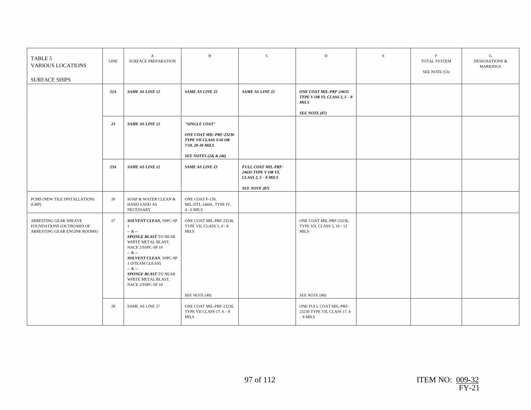
97 of 112 ITEM NO: 009-32 FY-21
TABLE 5
VARIOUS LOCATIONS
SURFACE SHIPS
LINE
A
SURFACE PREPARATION
B
C
D
E
F
TOTAL SYSTEM
SEE NOTE (53)
G
DESIGNATIONS &
MARKINGS
22A
SAME AS LINE 12
SAME AS LINE 22
SAME AS LINE 22
ONE COAT MIL-PRF-24635
TYPE V OR VI, CLASS 2, 5 – 8
MILS
SEE NOTE (87)
23
SAME AS LINE 12
"SINGLE COAT"
ONE COAT MIL-PRF-23236
TYPE VII CLASS 5/18 OR
7/18, 20-30 MILS
SEE NOTES (24) & (46)
23A
SAME AS LINE 12
SAME AS LINE 23
FULL COAT MIL-PRF-
24635 TYPE V OR VI,
CLASS 2, 5 – 8 MILS
SEE NOTE (87)
PCMS (NEW TILE INSTALLATION)
(GRP)
26
SOAP & WATER CLEAN &
HAND SAND AS
NECESSARY
ONE COAT F-150,
MIL-DTL-24441, TYPE IV,
4 - 6 MILS
ARRESTING GEAR SHEAVE
FOUNDATIONS (OUTBOARD OF
ARRESTING GEAR ENGINE ROOMS)
27
SOLVENT CLEAN, SSPC-SP
1
-- & --
SPONGE BLAST TO NEAR
WHITE METAL BLAST,
NACE 2/SSPC-SP 10
-- & --
SOLVENT CLEAN, SSPC-SP
1 (STEAM CLEAN)
-- & --
SPONGE BLAST TO NEAR
WHITE METAL BLAST,
NACE 2/SSPC-SP 10
ONE COAT MIL-PRF-23236,
TYPE VII, CLASS 5, 4 - 8
MILS
SEE NOTE (49)
ONE COAT MIL-PRF-23236,
TYPE VII, CLASS 5, 10 - 12
MILS
SEE NOTE (49)
28
SAME AS LINE 27
ONE COAT MIL-PRF-23236,
TYPE VII CLASS 17, 6 – 8
MILS
ONE FULL COAT MIL-PRF-
23236 TYPE VII, CLASS 17, 6
– 8 MILS
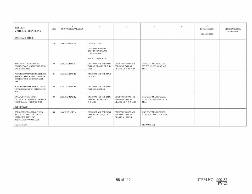
98 of 112 ITEM NO: 009-32 FY-21
TABLE 5
VARIOUS LOCATIONS
SURFACE SHIPS
LINE
A
SURFACE PREPARATION
B
C
D
E
F
TOTAL SYSTEM
SEE NOTE (53)
G
DESIGNATIONS &
MARKINGS
29
SAME AS LINE 27
"SINGLE COAT"
ONE COAT MIL-PRF-
23236 TYPE VII CLASS
17/18, 20-30 MILS
SEE NOTES (24) & (46)
ARRESTING GEAR SHEAVE
FOUNDATIONS (ARRESTING GEAR
ENGINE ROOMS)
30
SAME AS LINE 3
ONE COAT MIL-PRF-23236,
TYPE VI, CLASS 5 OR 7, 4-8
MILS
ONE STRIPE COAT MIL-
PRF-23236, TYPE VI,
CLASS 5 OR 7, 4-8 MILS
ONE COAT MIL-PRF-23236,
TYPE VI, CLASS 5 OR 7, 4-8
MILS
POWDER COATING FOR EXTERIOR
APPLICATIONS AND INTERIOR DRY
APPLICATIONS OF REMOVABLE
PARTS
31
SAME AS LINE 12
ONE COAT MIL-PRF-24712,
2-9 MILS
POWDER COATING FOR INTERIOR
WET OR IMMERSION APPLICATION
AREAS
32
SAME AS LINE 12
ONE COAT MIL-PRF-23236,
TYPE VIII, 2-9 MILS
CATAPULT WING VOIDS,
CATAPULT EXHAUST BLOWDOWN
TRUNKS, AND FREEING PORTS
SEE NOTE (38)
33
SAME AS LINE 12
ONE COAT MIL-PRF-23236,
TYPE VI, CLASS 5 OR 7,
4 - 8 MILS
ONE STRIPE COAT MIL-
PRF-23236, TYPE VI,
CLASS 5 OR 7, 4 - 8 MILS
ONE COAT MIL-PRF-23236,
TYPE VI, CLASS 5 OR 7, 4 - 8
MILS
BARRICADE STANCHIONS AND
WELLS, CATAPULT JET BLAST
DEFLECTOR PITS, AND
ASSOCIATED VOID SPACES
SEE NOTE (44)
34
SAME AS LINE 12
ONE COAT MIL-PRF-23236,
TYPE VI, CLASS 5, 4 - 8
MILS
ONE STRIPE COAT MIL-
PRF-23236, TYPE VI,
CLASS 5, 4 - 8 MILS
ONE COAT MIL-PRF-23236,
TYPE VI, CLASS 5, 4 - 8 MILS
SEE NOTE (35)

99 of 112 ITEM NO: 009-32 FY-21
TABLE 6
STEEL SURFACES
SUBMARINES
LINE
A
SURFACE PREPARATION
B
PRIMER
C
D
E
KEEL TO MAX BEAM
F
MAX BEAM TO UPPER
BOOTTOP
G
DRAFT MARKS
EXTERIOR SURFACES
(KEEL TO UPPER BOOTTOP)
(NON-SHT SURFACES BELOW
UPPER BOOTTOP)
1
NEAR WHITE METAL
BLAST, NACE 2/SSPC-SP
10
- OR -
WATERJETTING TO
NACE/SSPC-SP WJ-2/L
- OR -
SSPC-SP 10/L (WAB)/NACE
WAB-2/L
ONE COAT MIL- PRF-23236,
TYPE V OR VI CLASS 5 OR
7, 4 - 8 MILS
--OR—
ONE AC COATS MIL-PRF-
24647
TYPE I OR II, 5 - 7 MILS
--OR—
ONE COAT MIL-DTL-24441
TYPE IV, F-150, ,5 - 7 MILS
SEE NOTES (1A), (4A), (35A)
& (45A)
ONE STRIPE COAT MIL- PRF-
23236, TYPE V OR VI CLASS 5
OR 7, 4 - 8 MILS
--OR—
ONE AC STRIPE COAT MIL-
PRF-24647 TYPE I OR II, 5 - 7
MILS
--OR—
ONE STRIPE COAT MIL-DTL-
24441 TYPE IV, 5 - 7 MILS
SEE NOTES (1A), (4A), (35A) &
(45A)
ONE COAT MIL- PRF-23236,
TYPE V OR VI CLASS 5 OR
7, 4 - 8 MILS
--OR—
ONE AC COAT MIL-PRF-
24647 TYPE I OR II, 5 - 7
MILS
--OR—
ONE COAT MIL-DTL-24441
TYPE IV, F-153, 5 - 7 MILS
SEE NOTES (1A), (4A), (35A)
& (45A)
2 AF COATS MIL-PRF-
24647, TYPE I OR II, 5 -
7 MILS/COAT
SEE NOTES (2A),(4A) &
(45A)
2 AF COATS MIL-PRF-
24647, TYPE I OR II
BLACK, 5 - 7 MILS/COAT
SEE NOTES (3A), (4A) &
(45A)
ONE COAT
MIL-DTL-24631 F-186
--OR--
ONE COAT MIL-DTL-24441
TYPE IV, F-152
--OR--
ONE AC COAT MIL-PRF-
23236, WHITE, 3-4 MILS
--OR—
COMMERCIAL GRADE
WHITE AF
NON-SHT, EXTERIOR
SURFACES ABOVE THE
UPPER BOOTTOP (INCLUDES
DSRV/SRC SEATING
SURFACES)
2
SAME AS LINE ONE
ONE COAT MIL- PRF-23236,
TYPE V OR VI CLASS 5 OR 7,
4 - 8 MILS
--OR--
ONE COAT AC MIL-PRF-
24647, TYPE I OR II, 5 - 7
MILS
SEE NOTES (1A), (35A) &
(45A)
ONE STRIPE COAT MIL- PRF-
23236, TYPE V OR VI CLASS 5
OR 7, 4 - 8 MILS
--OR--
ONE STRIPE COAT AC MIL-
PRF-24647, TYPE I OR II, 5 - 7
MILS
SEE NOTES (1A), (35A) & (45A)
ONE COAT MIL- PRF-23236,
TYPE V OR VI CLASS 5 OR 7,
4 - 8 MILS
--OR--
ONE COAT AC MIL-PRF-
24647, TYPE I OR II, 5 - 7
MILS
FINAL COAT TO BE BLACK
SEE NOTES (1A), (32A), (35A)
& (45A)
3
SAME AS LINE ONE
ONE COAT MIL-DTL-24441
TYPE IV, F-150, 5 - 7 MILS
SEE NOTES (1A)& (35A)
ONE STRIPE COAT MIL-DTL-
24441 TYPE IV, 5 - 7 MILS
SEE NOTES (1A) & (35A)
ONE COAT MIL-DTL-24441
TYPE IV, F-153, 5 - 7 MILS
SEE NOTES (1A), (32A), &
(35A)
FOR MOORED TRAINING
SHIPS (MTS) ONLY; EXTERIOR
SURFACES ABOVE THE
UPPER BOOTTOP (NON-
IMMERSION SURFACES
ONLY)
4
SAME AS LINE ONE
ONE COAT MIL-PRF-23236,
TYPE V OR VI CLASS 5 OR 7,
4 - 8 MILS
--OR--
ONE COAT MIL-DTL-24441,
TYPE IV 5 - 7 MILS
SEE NOTES (1A) & (32A)
ONE STRIPE COAT MIL-PRF-
23236, TYPE V OR VI CLASS 5
OR 7, 4 - 8 MILS
--OR--
ONE STRIPE COAT MIL-DTL-
24441, TYPE IV 5 - 7 MILS
SEE NOTES (1A) & (32A)
ONE COAT MIL-PRF-23236,
TYPE V OR VI CLASS 5 OR 7,
4 - 8 MILS
--OR--
ONE COAT MIL-DTL-24441,
TYPE IV 5 - 7 MILS
SEE NOTES (1A) & (32A)
UPPER BOOTTOP TO
TOP OF SAIL ONLY:
ONE COAT MIL-PRF-
24635, 5 - 8 MILS
-&-
ONE COAT MIL-PRF-
24667, TYPE I OR X,
COMP G
UNTILED (NON-SHT
COVERED) FOOT TRAFFIC
AREAS TO BE COVERED
WITH NONSKID SYSTEM (ALL
CLASSES OF SUBMARINES)
5
SAME AS LINE ONE
ONE COAT MIL-DTL-24441
TYPE IV F-150, 5 - 7 MILS
SEE NOTES (1A) & (32A)
ONE STRIPE COAT MIL-DTL-
24441 TYPE IV, 5 - 7 MILS
SEE NOTES (1A) & (32A)
ONE COAT MIL-DTL-24441
TYPE IV, F-153, 5 - 7 MILS
SEE NOTES (1A) & (32A)
NONSKID SYSTEM:
MIL-PRF-24667, TYPE I
OR X, COMP G
SEE NOTE (44A)

100 of 112 ITEM NO: 009-32 FY-21
TABLE 6
STEEL SURFACES
SUBMARINES
LINE
A
SURFACE PREPARATION
B
PRIMER
C
D
E
KEEL TO MAX BEAM
F
MAX BEAM TO UPPER
BOOTTOP
G
DRAFT MARKS
6
SAME AS LINE ONE
ONE COAT MIL- PRF-23236,
TYPE V OR VI CLASS 5 OR 7,
4 - 8 MILS
--OR—
ONE COAT AC MIL-PRF-
24647, TYPE I OR II, 5 - 7
MILS
SEE NOTES (1A), (32A), &
(45A)
ONE STRIPE COAT MIL- PRF-
23236, TYPE V OR VI CLASS 5
OR 7, 4 - 8 MILS
--OR—
ONE STRIPE COAT AC MIL-
PRF-24647, TYPE I OR II, 5 - 7
MILS
SEE NOTES (1A), (32A), &
(45A)
ONE COAT MIL- PRF-23236,
TYPE V OR VI CLASS 5 OR 7,
4 - 8 MILS
--OR—
ONE COAT AC MIL-PRF-
24647, TYPE I OR II, 5 - 7
MILS
FINAL COAT TO BE BLACK
SEE NOTES (1A), (32A), &
(45A)
SAME AS LINE 5
INTERIOR SURFACES OF
RUDDERS, PLANES,
STABILIZERS (SYNTACTIC
FILLED VOIDS)
7
HAND TOOL CLEAN,
SSPC-SP 2
2 COATS TT-P-645 F-84
(PRIMER), 1-2 MILS/COAT
-OR-
ONE COAT PRIMER MIL-
PRF-23236, TYPE V OR VI, 4-
6 MILS
-OR-
ONE COAT MIL-DTL-24441,
TYPE IV, F-150, 4-6 MILS
ONE STRIPE COAT
TT-P-645, 1-2 MILS
-OR-
ONE STRIPE COAT
MIL-PRF-23236, TYPE V OR VI,
4-6 MILS
-OR-
ONE STRIPE COAT
MIL-DTL-24441, TYPE IV, 4-6
MILS

101 of 112 ITEM NO: 009-32 FY-21
TABLE 6
GRP FIBERGLASS
SURFACES
SUBMARINES
LINE
A
SURFACE PREPARATION
B
PRIMER
C
D
E
KEEL TO MAX BEAM
F
MAX BEAM TO UPPER
BOOTTOP
G
DRAFT MARKS
UNBOOTED GRP BOW
DOMES ABOVE UPPER
BOOTTOP
SEE NOTE (34A)
8
LOW PRESSURE WATER
CLEAN
SEE NOTE (42A)
ONE COAT MIL-DTL-24441,
TYPE IV, F-150, 4 - 6 MILS
-- & --
ONE COAT MIL-DTL-24441
TYPE IV, F-153 OR F-154, 4 -
6 MILS
--OR--
2 COATS MIL-PRF-24647 4 - 6
MIL/COAT
--OR--
2 COATS MIL-PRF-23236
TYPE V OR VI, CLASS 5 OR
7, 4 - 6 MILS/COAT
SEE NOTES (32A), (38A), &
(45A)
UNBOOTED GRP BOW
DOMES BELOW UPPER
BOOTTOP
SEE NOTE (34A)
9
SAME AS LINE 8
ONE COAT MIL-DTL-24441,
TYPE IV, F-150, 4 - 6 MILS
--OR--
ONE COAT MIL-PRF-24647 4
- 6 MIL/COAT DARK GRAY
SEE NOTES (4A) & (45A)
TWO COATS AF MIL-
PRF-24647, TYPE I OR II
CLASS 1, 4 - 6
MIL/COAT
SEE NOTES (2A), (4A),
(38A), & (45A)
TWO COATS AF MIL-PRF-
24647, TYPE I OR II CLASS
1, 4 - 6 MIL/COAT
SEE NOTES (3A), (4A),
(38A), & (45A)
BOOTED GRP BOW DOMES
ABOVE UPPER BOOTTOP
SEE NOTE (34A)
10
LOW PRESSURE WATER
CLEAN
SEE NOTE (43A)
PRIOR TO INSTALLING THE
BOOT - ONE COAT MIL-
DTL-24441, TYPE IV, F-150,
2-4 MILS
AFTER BOOT
INSTALLATION
ONE COAT NAVY
FORMULA 187, 2-3 MILS
SEE NOTES (38A) & (46A)
BOOTED GRP BOW DOMES,
CHIN ARRAY, & LIGHT
WEIGHT WIDE APERTURE
ARRAY (LWWAA) BELOW
UPPER BOOTTOP
SEE NOTE (34A)
11
SAME AS LINE 10
PRIOR TO INSTALLING THE
BOOT - ONE COAT MIL-
DTL-24441, TYPE IV, F-150,
2-4 MILS
AFTER BOOT
INSTALLATION
ONE COAT NAVY
FORMULA 184, 2-3 MILS
TWO COATS AF MIL-
PRF-24647, TYPE I
CLASS 3, 4 - 6
MIL/COAT
SEE NOTES (2A), (4A),
& (38A), & (45A)
TWO COATS AF MIL-PRF-
24647, TYPE I CLASS 3, 4 -
6 MIL/COAT
SEE NOTES (3A), (4A), &
(38A), & (45A)
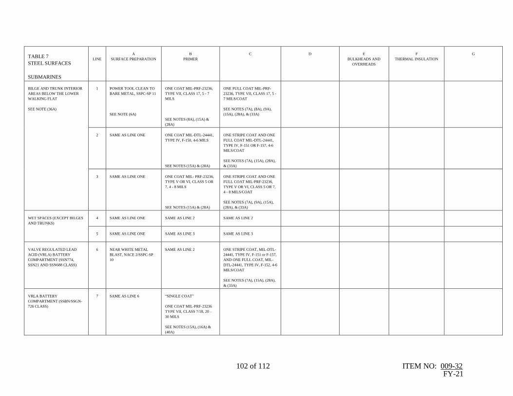
102 of 112 ITEM NO: 009-32 FY-21
TABLE 7
STEEL SURFACES
SUBMARINES
LINE
A
SURFACE PREPARATION
B
PRIMER
C
D
E
BULKHEADS AND
OVERHEADS
F
THERMAL INSULATION
G
BILGE AND TRUNK INTERIOR
AREAS BELOW THE LOWER
WALKING FLAT
SEE NOTE (36A)
1
POWER TOOL CLEAN TO
BARE METAL, SSPC-SP 11
SEE NOTE (6A)
ONE COAT MIL-PRF-23236,
TYPE VII, CLASS 17, 5 - 7
MILS
SEE NOTES (8A), (15A) &
(28A)
ONE FULL COAT MIL-PRF-
23236, TYPE VII, CLASS 17, 5 -
7 MILS/COAT
SEE NOTES (7A), (8A), (9A),
(15A), (28A), & (33A)
2
SAME AS LINE ONE
ONE COAT MIL-DTL-24441,
TYPE IV, F-150, 4-6 MILS
SEE NOTES (15A) & (28A)
ONE STRIPE COAT AND ONE
FULL COAT MIL-DTL-24441,
TYPE IV, F-151 OR F-157, 4-6
MILS/COAT
SEE NOTES (7A), (15A), (28A),
& (33A)
3
SAME AS LINE ONE
ONE COAT MIL- PRF-23236,
TYPE V OR VI, CLASS 5 OR
7, 4 - 8 MILS
SEE NOTES (15A) & (28A)
ONE STRIPE COAT AND ONE
FULL COAT MIL-PRF-23236,
TYPE V OR VI, CLASS 5 OR 7,
4 - 8 MILS/COAT
SEE NOTES (7A), (9A), (15A),
(28A), & (33A)
WET SPACES (EXCEPT BILGES
AND TRUNKS)
4
SAME AS LINE ONE
SAME AS LINE 2
SAME AS LINE 2
5
SAME AS LINE ONE
SAME AS LINE 3
SAME AS LINE 3
VALVE REGULATED LEAD
ACID (VRLA) BATTERY
COMPARTMENT (SSN774,
SSN21 AND SSN688 CLASS)
6
NEAR WHITE METAL
BLAST, NACE 2/SSPC-SP
10
SAME AS LINE 2
ONE STRIPE COAT, MIL-DTL-
24441, TYPE IV, F-151 or F-157,
AND ONE FULL COAT, MIL-
DTL-24441, TYPE IV, F-152, 4-6
MILS/COAT
SEE NOTES (7A), (15A), (28A),
& (33A)
VRLA BATTERY
COMPARTMENT (SSBN/SSGN-
726 CLASS)
7
SAME AS LINE 6
“SINGLE COAT”
ONE COAT MIL-PRF-23236
TYPE VII, CLASS 7/18, 20 –
30 MILS
SEE NOTES (15A), (16A) &
(40A)

103 of 112 ITEM NO: 009-32 FY-21
TABLE 7
STEEL SURFACES
SUBMARINES
LINE
A
SURFACE PREPARATION
B
PRIMER
C
D
E
BULKHEADS AND
OVERHEADS
F
THERMAL INSULATION
G
VA CLASS BATTERY
COMPARTMENT (DECK AND
BHDS UP TO 62” ABOVE TOP
STEP OF DECK)
8
SAME AS LINE ONE
TEK-HAZ RED PRIME
COAT,
16-20 MILS
SEE NOTES (24A) & (28A)
TEK-HAZ GRAY TOPCOAT,
16-20 MILS
SEE NOTES (24A), (28A), &
(33A)
VA CLASS BATTERY
COMPARTMENT (OVHD AND
BHDS ABOVE 62” ABOVE TOP
STEP OF DECK)
9
SAME AS LINE ONE
ONE COAT MIL-DTL-24441,
TYPE IV, F-150, 2 - 3 MILS
SEE NOTES (24A) & (28A)
2 COATS MIL-PRF-
24635, TYPE II, CLASS
1, 4-6 MILS/ COAT
SEE NOTES (24A),
(28A), & (33A)
TRUNK INTERIORS,
UNINSULATED AREA ABOVE
THE LOWER FLAT
(INCLUDING UPPER HATCH
COVER)
SEE NOTE (36A)
10
SAME AS LINE ONE
SEE NOTE (13A)
SAME AS LINE ONE
ONE COAT MIL-PRF-23236,
TYPE VII, CLASS 17, 5 - 7
MILS
SEE NOTE (7A), (8A), (9A),
(15A), (28A), & (33A)
11
SAME AS LINE ONE
SAME AS LINE 2
ONE COAT MIL-DTL-24441,
TYPE IV, F-151 OR F-157, 4-6
MILS
SEE NOTES (7A), (15A), &
(28A)
ONE COAT MIL-DTL-
24607, 1-2 MILS
SEE NOTES (7A), (9A),
(10A), (11A), (12A),
(28A) & (33A)
12
SAME AS LINE ONE
SAME AS LINE 3
ONE COAT MIL-PRF-23236,
TYPE V OR VI, CLASS 5 OR 7,
4 - 8 MILS
SEE NOTES (7A), (9A), (15A),
& (28A)
SAME AS LINE 11
TRUNK INTERIORS UNDER
INSULATION ABOVE THE
LOWER FLAT
SEE NOTE (36A)
13
SAME AS LINE ONE
SAME AS LINE 2
ONE FULL COAT MIL-DTL-
24441, TYPE IV,
CONTRASTING COLOR, 4-6
MILS
SEE NOTES (15A), (28A), &
(33A)
14
SAME AS LINE ONE
SAME AS LINE 3
ONE FULL COAT MIL-PRF-
23236, TYPE V OR VI, CLASS 5
OR 7, 4 - 8 MILS
SEE NOTES (15A), (28A), &
(33A)

104 of 112 ITEM NO: 009-32 FY-21
TABLE 7
STEEL SURFACES
SUBMARINES
LINE
A
SURFACE PREPARATION
B
PRIMER
C
D
E
BULKHEADS AND
OVERHEADS
F
THERMAL INSULATION
G
MACHINERY SPACES (ENGINE
ROOMS AND AUXILIARY
MACHINERY ROOMS)
UNINSULATED PRESSURE
HULL
15
SAME AS LINE ONE
SAME AS LINE 2
SAME AS LINE 11
2 COATS MIL-DTL-24607, 1-2
MILS/COAT
SEE NOTES (7A), (9A), (10A),
(11A), (28A) & (33A)
16
SAME AS LINE ONE
SAME AS LINE 3
SAME AS LINE 12
SAME AS LINE 15
MACHINERY SPACES (ENGINE
ROOMS AND AUXILIARY
MACHINERY ROOMS)
PRESSURE HULL TO BE
COVERED BY INSULATION
17
SAME AS LINE ONE
SAME AS LINE 2
SAME AS LINE 2
18
SAME AS LINE ONE
SAME AS LINE 3
SAME AS LINE 3
MACHINERY SPACE
OVERHEADS AND
BULKHEADS
19
SAME AS LINE ONE
ONE COAT TT-P-645 F-84, 1-
2 MILS
2 COATS MIL-DTL-24607,
1 - 2 MILS/COAT
DECKS WITHOUT COVERINGS
20
SAME AS LINE ONE
ONE COAT MIL-DTL-24441,
TYPE IV, 2-4 MILS
SEE NOTES (7A), (15A),
(25A), (28A), & (33A)
ONE COAT MIL-DTL-24441,
TYPE IV, 2-4 MILS
SEE NOTES (7A), (15A), (28A),
& (33A)
21
SAME AS LINE ONE
SAME AS LINE 3
SAME AS LINE 14
22
SAME AS LINE ONE
ONE COAT TT-P-645, F-84, 1-
2 MILS
SEE NOTES (28A) & (33A)
2 COATS MIL-PRF-24635, 5 - 8
MILS/COAT
SEE NOTES (7A), (28A), &
(33A)
23
SAME AS LINE ONE
ONE COAT MIL-PRF-32584,
TYPES I OR II, CLASS 2, 10 –
12 MILS
SEE NOTE (30A)
ONE COAT MIL-PRF-32584,
TYPES I OR II, CLASS 2, 10 –
12 MILS
SEE NOTE (30A)
DECKS WITH COVERINGS
24
SAME AS LINE ONE
ONE COAT MIL-DTL-24441,
TYPE IV, F-150, 2 - 4 MILS
-OR-
ONE COAT MIL- PRF-23236,
TYPE V OR VI, CLASS 5 OR
7, 4 - 8 MILS
SEE NOTES (6A), (15A),
(28A) & (33A)

105 of 112 ITEM NO: 009-32 FY-21
TABLE 7
STEEL SURFACES
SUBMARINES
LINE
A
SURFACE PREPARATION
B
PRIMER
C
D
E
BULKHEADS AND
OVERHEADS
F
THERMAL INSULATION
G
25
SAME AS LINE ONE
SAME AS LINE 21
ENSOLITE INSULATION
(OVERCOAT)
26
DETERGENT WASH AND
RINSE
2 COATS MIL-DTL-
24607, 1-2 MILS/COAT
SEE NOTES (7A), (9A),
(10A), (11A), (28A) &
(33A)
POLYIMIDE INSULATION
(OVERCOAT)
27
SAME AS LINE 26
SAME AS LINE 26
28
SAME AS LINE 26
2 COATS MIL-PRF-
24596, 1-2 MILS/COAT
-OR-
2 COATS F-25A, 1-2
MILS/COAT
SEE NOTES (28A) &
(33A)
DRY VOIDS
29
SAME AS LINE ONE
SAME AS LINE 3
SAME AS LINE 14
30
SAME AS LINE ONE
SAME AS LINE 20
SAME AS LINE 20

106 of 112 ITEM NO: 009-32 FY-21
TABLE 8
STEEL SURFACES
SUBMARINES
LINE
A
SURFACE PREPARATION
B
PRIMER
C
D
E
F
G
TOTAL
POTABLE WATER TANKS
SEE NOTES (29A), (31A) & (34A)
1
NEAR WHITE METAL
BLAST, NACE 2/SSPC-SP
10
ONE COAT MIL-PRF-23236,
TYPE VII, CLASS 9, 4 - 8
MILS
SEE NOTES (15A), (17A),
(39A), (5A), & (37A)
ONE COAT MIL-PRF-23236,
TYPE VII, CLASS 9, 10-12
MILS WHITE OR OFF-
WHITE
SEE NOTES (15A), (39A), &
(37A)
2
SAME AS LINE ONE
"SINGLE COAT"
ONE COAT MIL-PRF-23236
TYPE VII CLASS 9/18, 20-30
MILS WHITE OR OFF-
WHITE
SEE NOTES (15A), (17A),
(39A), (5A), (37A), & (40A)
3
SAME AS LINE ONE
ONE COAT MIL-DTL-24441,
TYPE III, F-150, 2 - 4 MILS
SEE NOTES (15A), (17A), &
(21A)
ONE STRIPE COAT MIL-
DTL-24441, TYPE III, 2 - 4
MILS
SEE NOTES (15A), & (21A)
ONE COAT MIL-DTL-
24441, TYPE III, 2 - 4 MILS
SEE NOTES (15A) & (21A)
ONE STRIPE COAT MIL-
DTL-24441, TYPE III, 2-4
MILS
SEE NOTES (15A) & (21A)
ONE COAT MIL-DTL-
24441, TYPE III, F-152, 2-4
MILS DFT AT ADEQUATE
THICKNESS TO MEET
COATING RANGE
SEE NOTES (15A), (21A), &
(27A)
TOTAL SYSTEM
8 -12 MILS (ON
AREAS WITHOUT
STRIPE COAT)
SEE NOTE (22A)
RESERVE FEEDWATER TANKS
SEE NOTES (29A), (31A) & (34A)
4
SAME AS LINE ONE
ONE COAT MIL-DTL-24441,
TYPE III, F-150, 2 - 4 MILS
SEE NOTES (15A), (17A), &
(21A)
ONE STRIPE COAT MIL-
DTL-24441 TYPE III F-152,
2 - 4 MILS
SEE NOTES (15A) & (21A)
ONE COAT MIL-DTL-
24441, TYPE III F-151,
2 - 4 MILS
SEE NOTES (15A) & (21A)
ONE STRIPE COAT MIL-
DTL-24441, TYPE III, F-150,
2 - 4 MILS
SEE NOTES (15A) & (21A)
ONE COAT MIL-DTL-24441
TYPE III F-152, 2 - 4 MILS
SEE NOTES (15A) & (21A)
TOTAL SYSTEM
8 MILS MIN
AUXILIARY TANKS, ACR HOLDING
TANKS (MTS), DEPTH CONTROL TANKS,
NFO EXPANSION TANK, SEAWATER
EXPANSION TANK, SECONDARY
SHIELD WATER OVERFLOW TANK
(MTS), TRIM TANKS, WATER ROUND
TORPEDO (WRT) TANKS
SEE NOTE (29A)
5
SAME AS LINE ONE
"SINGLE COAT"
ONE COAT MIL-PRF-23236,
TYPE VII, CLASS 7/18, 20-30
MILS
SEE NOTES (15A), (16A),
(17A), (40A), & (5A)
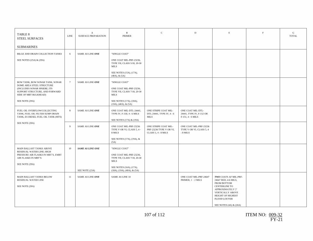
107 of 112 ITEM NO: 009-32 FY-21
TABLE 8
STEEL SURFACES
SUBMARINES
LINE
A
SURFACE PREPARATION
B
PRIMER
C
D
E
F
G
TOTAL
BILGE AND DRAIN COLLECTION TANKS
SEE NOTES (25A) & (29A)
6
SAME AS LINE ONE
"SINGLE COAT"
ONE COAT MIL-PRF-23236,
TYPE VII, CLASS 5/18, 20-30
MILS
SEE NOTES (15A), (17A),
(40A), & (5A)
BOW TANK, BOW SONAR TANK, SONAR
DOME AREA STEEL STRUCTURE
(INCLUDES SONAR SPHERE, ITS
SUPPORT STRUCTURE, AND FORWARD
SIDE OF MBT BULKHEAD)
SEE NOTE (29A)
7
SAME AS LINE ONE
"SINGLE COAT"
ONE COAT MIL-PRF-23236,
TYPE VII, CLASS 7/18, 20-30
MILS
SEE NOTES (17A), (18A),
(19A), (40A), & (5A)
FUEL OIL OVERFLOW/COLLECTING
TANK, FUEL OIL FILTER SUMP DRAIN
TANK, ES DIESEL FUEL OIL TANK (MTS)
SEE NOTE (29A)
8
SAME AS LINE ONE
ONE COAT MIL-DTL-24441,
TYPE IV, F-150, 4 - 6 MILS
SEE NOTES (17A) & (19A)
ONE STRIPE COAT MIL-
DTL-24441, TYPE IV, 4 - 6
MILS
ONE COAT MIL-DTL-
24441, TYPE IV, F-152 OR
F-151, 4 - 6 MILS
9
SAME AS LINE ONE
ONE COAT MIL-PRF-23236
TYPE V OR VI, CLASS 5, 4 -
8 MILS
SEE NOTES (17A), (19A), &
(5A)
ONE STRIPE COAT MIL-
PRF-23236 TYPE V OR VI,
CLASS 5, 4 - 8 MILS
ONE COAT MIL-PRF-23236
TYPE V OR VI, CLASS 5, 4
- 8 MILS
MAIN BALLAST TANKS ABOVE
RESIDUAL WATER LINE; HIGH
PRESSURE AIR FLASKS IN MBT’S, EMBT
AIR FLASKS IN MBT’S
SEE NOTE (29A)
10
SAME AS LINE ONE
SEE NOTE (23A)
"SINGLE COAT"
ONE COAT MIL-PRF-23236,
TYPE VII, CLASS 7/18, 20-30
MILS
SEE NOTES (16A), (17A),
(18A), (19A), (40A), & (5A)
MAIN BALLAST TANKS BELOW
RESIDUAL WATER LINE
SEE NOTE (29A)
11
SAME AS LINE ONE
SAME AS LINE 10
ONE COAT MIL-PRF-24647
PRIMER, 1 – 2 MILS
TWO COATS AF MIL-PRF-
24647 RED, 4-6 MILS,
FROM BOTTOM
CENTERLINE TO
APPROXIMATELY 2’
VERTICALLY ABOVE
HEIGHT OF HIGHEST
FLOOD LOUVER
SEE NOTES (4A) & (26A)

108 of 112 ITEM NO: 009-32 FY-21
TABLE 8
STEEL SURFACES
SUBMARINES
LINE
A
SURFACE PREPARATION
B
PRIMER
C
D
E
F
G
TOTAL
MAIN INDUCTION SUMP TANK, MISSILE
COMPENSATING TANKS
SEE NOTE (29A)
12
SAME AS LINE ONE
"SINGLE COAT"
ONE COAT MIL-PRF-23236,
TYPE VII, CLASS 7/18, 20-30
MILS
SEE NOTES (15A), (17A),
(40A), & (5A)
TORPEDO IMPULSE TANKS
SEE NOTE (29A)
13
SAME AS LINE ONE
ONE COAT MIL-DTL-24441,
TYPE IV, F-150, 4-6 MILS
SEE NOTES (15A) & (17A),
ONE STRIPE COAT MIL-
DTL-24441, TYPE IV, 4-6
MILS
SEE NOTES (15A) & (17A)
ONE COAT MIL-DTL-
24441, TYPE IV, F-152 OR
F-151, 4-6 MILS
SEE NOTES (15A) & (17A)
14
SAME AS LINE ONE
ONE COAT MIL-PRF-23236,
TYPE V OR VI, CLASS 7,
GRADE B OR C, 4 - 8 MILS
SEE NOTES (15A), (17A), &
(5A)
ONE STRIPE COAT MIL-
PRF-23236, TYPE V OR VI,
CLASS 7, GRADE B OR C, 4
- 8 MILS
SEE NOTES (15A) & (17A)
ONE COAT MIL-PRF-23236,
TYPE V OR VI, CLASS 7,
GRADE B OR C, 4 - 8 MILS
SEE NOTES (15A) & (17A)
TORPEDO IMPULSE TANKS (SSBN/SSGN
ONLY)
SEE NOTE (29A)
15
SAME AS LINE ONE
"SINGLE COAT"
ONE COAT MIL-PRF-23236,
TYPE VII, CLASS 7/18, 20-30
MILS
SEE NOTES (15A), (17A),
(19A), (40A), & (5A)
SANITARY TANKS
SEE NOTE (29A)
16
SAME AS LINE ONE
ONE COAT MIL-PRF-23236,
TYPE VII, CLASS 13, 4 - 8
MILS
SEE NOTES (15A), (17A), &
(5A)
ONE COAT MIL-PRF-23236,
TYPE VII, CLASS 13, 10-12
MILS
SEE NOTE (15A)
17
SAME AS LINE ONE
“SINGLE COAT”
ONE COAT MIL-PRF-23236,
TYPE VII, CLASS 13/18, 20-
30 MILS
SEE NOTES (15A), (17A),
(40A), & (5A)

109 of 112 ITEM NO: 009-32 FY-21
TABLE 8
STEEL SURFACES
SUBMARINES
LINE
A
SURFACE PREPARATION
B
PRIMER
C
D
E
F
G
TOTAL
STEAM PLANT SURGE TANKS (MTS)
SEE NOTE (29A)
18
SAME AS LINE ONE
ONE COAT OF APEXIOR
NO. 1 (DAMPNEY CO.). 2 - 4
MILS
SEE NOTE (47A)
ONE COAT OF APEXIOR
NO. 1 (DAMPNEY CO.), 2 -
4 MILS
SEE NOTE (47A)
WASTE OIL COLLECTING TANKS,
WASTE OIL OVERFLOW TANKS, ENGINE
ROOM OIL COLLECTION TANKS
SEE NOTE (29A)
19
SAME AS LINE ONE
ONE COAT MIL-PRF-23236,
TYPE VII, CLASS 5, 4 - 8
MILS
SEE NOTES (15A), (17A), &
(5A)
ONE COAT MIL-PRF-23236,
TYPE VII, CLASS 5, 10 - 12
MILS
SEE NOTE (15A)
20
SAME AS LINE ONE
"SINGLE COAT"
ONE COAT MIL-PRF-23236,
TYPE VII, CLASS 5/18, 20-30
MILS
SEE NOTES (15A), (17A),
(40A), & (5A)
FREE FLOOD AREAS AND RECESSES:
INSIDE SURFACES OF FAIRWATER,
UNDERSIDE OF SUPERSTRUCTURE,
CHAIN LOCKERS, INTERIOR SURFACES
OF STEEL DOMES, SHAFT TUBE
INTERIOR SURFACES (WHEN SHAFT IS
REMOVED), BOW DOME ACCESS FREE
FLOOD AREA, BSY-1 RECESS (FRAME
(FR) 29-30 STARBOARD (STBD)), 726
CLASS ACCESS SONAR DOME RECESS
(FR 6-7 PORT), 726 CLASS SONAR
SPHERE EXTERNAL SURFACES, 726
CLASS SONAR TRUNK EXTERNAL
SURFACES, 726 CLASS SONAR DOME
BULKHEAD (BHD) (FR 4), 726 CLASS
SONAR CAVITY (FR 6-8), 726 CLASS
SONAR DOME ACCESS TRUNK (FR 6-7),
CAPSTAN RECESS, SONAR
PENETRATION SPLICE TRUNK
RECESSES (PORT AND STBD), SONAR
CABLE TRUNK, EMERGENCY TOWING
PENDANT, BETWEEN BLADES COVER
PLATES (BBCP) RECESS, 726 CLASS MSS
RECESS AT BHD 4, SHAFT TUBE HULL
INSERTS
SEE NOTE (29A)
21
SAME AS LINE ONE
"SINGLE COAT"
ONE COAT MIL-PRF-23236,
TYPE VII, CLASS 7/18, 20-30
MILS
SEE NOTES (1A), (32A),
(40A), & (5A)

110 of 112 ITEM NO: 009-32 FY-21
TABLE 8
STEEL SURFACES
SUBMARINES
LINE
A
SURFACE PREPARATION
B
PRIMER
C
D
E
F
G
TOTAL
FREE FLOOD AREAS AND RECESSES:
TORPEDO TUBE RECESS, AFT FREE
FLOOD AREA (MUD TANK), EJECTION
PUMP RECESS, SECONDARY
PROPULSION MOTOR (SPM) RECESS,
SSN-688 CLASS BQN-17, BSY-1 OR
AN/BBQ-10/V(1) RECESS (FR 14-15 PORT
BOTTOM), 726 CLASS ANCHOR RECESS
SEE NOTE (29A)
22
SAME AS LINE ONE
SAME AS LINE 21
SAME AS LINE 21
ONE COAT MIL-PRF-24647
PRIMER, 1 – 2 MILS
2 AF COATS MIL-PRF-
24647 TYPE I OR II, RED, 4
– 6 MILS/COAT
SEE NOTE (4A)
ALL OTHER FREE FLOOD AREAS,
RECESSES BELOW UPPER BOOTTOP
(APPLIES TO FREE FLOOD AREAS,
RECESSES, AND VOIDS NOT LISTED
ELSEWHERE IN THIS TABLE)
SEE NOTE (29A)
23
SAME AS LINE ONE
"SINGLE COAT”
ONE COAT MIL-PRF-23236,
TYPE VII, CLASS 7/18, 20-30
MILS
SEE NOTES (1A), (16A),
(17A), (26A), (32A), (40A), &
(5A)
SAME AS LINE 22
SAME AS LINE 22
24
SAME AS LINE ONE
ONE COAT MIL-PRF-23236,
TYPE VII, CLASS 7, 4 – 8
MILS
SEE NOTES (1A), (17A),
(36A), & (5A)
ONE COAT MIL-PRF-23236,
TYPE VII, CLASS 7, 10 – 12
MILS
SEE NOTE (4A)
SAME AS LINE 22
SAME AS LINE 22
25
SAME AS LINE ONE
ONE COAT MIL-PRF-23236,
TYPE V OR VI, CLASS 5 OR
7, 4 - 8 MILS
-OR-
ONE COAT MIL-DTL-24441
TYPE IV, F-150, 4 - 6 MILS
-OR-
ONE AC COAT MIL-PRF-
24647, TYPE I OR II, 4-6
MILS
SEE NOTES (1A), (16A),
(17A), & (5A)
ONE STRIPE COAT MIL-
PRF-23236, TYPE V OR VI,
CLASS 5 OR 7, 4 - 8 MILS
-OR-
ONE STRIPE COAT MIL-
DTL-24441 TYPE IV, F-151
OR F-152, 4-6 MILS
-OR-
ONE AC STRIPE COAT
MIL-PRF-24647, TYPE I OR
II, 4-6 MILS
ONE COAT MIL-PRF-23236,
TYPE V OR VI, CLASS 5
OR 7, 4 - 8 MILS
-OR-
ONE COAT MIL-DTL-24441
TYPE IV, F-151 OR F-152, 4-
6 MILS
-OR-
ONE AC COAT MIL-PRF-
24647, TYPE I OR II, 4-6
MILS
SEE NOTE (4A)
SAME AS LINE 22
SAME AS LINE 22

111 of 112 ITEM NO: 009-32 FY-21
TABLE 8
STEEL SURFACES
SUBMARINES
LINE
A
SURFACE PREPARATION
B
PRIMER
C
D
E
F
G
TOTAL
ALL OTHER FREE FLOOD AREAS,
RECESSES ABOVE UPPER BOOTTOP
(APPLIES TO FREE FLOOD AREAS,
RECESSES, AND VOIDS NOT LISTED
ELSEWHERE IN THIS TABLE)
SEE NOTE (29A)
26
SAME AS LINE ONE
"SINGLE COAT"
ONE COAT MIL-PRF-23236,
TYPE VII, CLASS 7/18, 20-30
MILS
SEE NOTES (1A), (16A),
(17A), (26A), (32A), (40A), &
(5A)
27
SAME AS LINE ONE
ONE COAT MIL-PRF-23236,
TYPE VII, CLASS 7, 4 – 8
MILS
SEE NOTES (1A), (16A),
(17A), (36A),& (5A)
ONE COAT MIL-PRF-23236,
TYPE VII, CLASS 7, 10 – 12
MILS
SEE NOTES (32A) & (36A)
28
SAME AS LINE ONE
ONE COAT MIL-PRF-23236,
TYPE V OR VI, CLASS 5 OR
7, 4 - 8 MILS
-OR-
ONE COAT MIL-DTL-24441
TYPE IV, F-150, 4 - 6 MILS
-OR-
ONE AC COAT MIL-PRF-
24647, TYPE I OR II, 4-6
MILS
SEE NOTES (1A), (16A) &
(17A)
ONE STRIPE COAT MIL-
PRF-23236, TYPE V OR VI,
CLASS 5 OR 7, 4 - 8 MILS
-OR-
ONE STRIPE COAT MIL-
DTL-24441 TYPE IV, F-151
OR F-152, 4-6 MILS
-OR-
ONE AC STRIPE COAT
MIL-PRF-24647, TYPE I OR
II, 4-6 MILS
ONE COAT MIL-PRF-23236,
TYPE V OR VI, CLASS 5
OR 7, 4 - 8 MILS
-OR-
ONE COAT MIL-DTL-24441
TYPE IV, F-151 OR F-152, 4-
6 MILS
-OR-
ONE AC COAT MIL-PRF-
24647, TYPE I OR II, 4-6
MILS
SEE NOTE (32A)
CLEAN FUEL OIL, HYDRAULIC OIL,
LUBE OIL SLUDGE, & HYDROPHONE
TANKS
SEE NOTES (29A) & (20A)
29
POWER TOOL CLEAN,
SSPC-SP 3
ONE COAT MIL-DTL-24441,
TYPE IV, F-150, 4-6 MILS
SEE NOTES (15A) & (17A)
MIL-DTL-24441, TYPE IV,
F-152 OR F-151, 4-6 MILS
SEE NOTE (15A)
30
COMMERCIAL BLAST,
NACE 3/SSPC-SP 6 OR
POWER TOOL CLEAN TO
BARE METAL SSPC-SP 11
NORMAL FUEL OIL
(688 AND 726 CLASS: FROM BASELINE
TO 4 FEET ABOVE BASELINE,
774 CLASS: FROM BASELINE TO 9 FEET
ABOVE BASELINE)
SEE NOTE (29A) & (20A)
31
SAME AS LINE 30
32
SAME AS LINE ONE
SEE NOTE (14A)
ONE COAT MIL-DTL-24441,
TYPE IV, F-150, 4 - 6 MILS
SEE NOTE (15A)
ONE STRIPE COAT MIL-
DTL-24441, TYPE IV, 4 - 6
MILS
SEE NOTE (15A)
ONE COAT MIL-DTL-
24441, TYPE IV, F-152 OR
F-151, 4 - 6 MILS
SEE NOTE (15A)

112 of 112 ITEM NO: 009-32 FY-21
TABLE 8
STEEL SURFACES
SUBMARINES
LINE
A
SURFACE PREPARATION
B
PRIMER
C
D
E
F
G
TOTAL
TANK MANHOLE COVERS
SEE NOTE (29A)
33
SAME AS LINE ONE
ONE COAT MIL-PRF-23236,
TYPE VIII, 5-9 MILS
--OR--
USE APPROVED COATING
SYSTEM SPECIFIED FOR
TANK OR FREEFLOOD
SEE NOTES (15A), (21A),
(31A), & (41A)
FREEFLOOD ACCESS COVERS
SEE NOTE (29A)
34
SAME AS LINE ONE
2 COATS AC MIL-PRF-24647,
TYPE I OR II, 4-6
MILS/COAT
SEE NOTE (32A)
2 AF COATS MIL-PRF-
24647, TYPE I OR II,
4–6 MILS/COAT
SEE NOTES (2A), (3A),
(4A), (7A), & (32A)
35
SAME AS LINE ONE
TWO COATS MIL- PRF-
23236, TYPE V OR VI CLASS
5 OR 7, 4 - 8 MILS/COAT
SEE NOTE (32A)
SAME AS LINE 34
36
SAME AS LINE ONE
ONE COAT MIL-DTL-24441,
TYPE IV, F-150, 4-6 MILS
--- & ---
ONE COAT MIL-DTL-24441,
TYPE IV, F-151 OR F-152, 4-6
MILS
SEE NOTE (32A)
SAME AS LINE 34