standard hydraulic power units installation and ... · pdf fileparker hannifin corporation...
TRANSCRIPT
Standard HydraulicPower UnitsInstallation andMaintenance Manual
D, H, V-Pak andCustom Power Units
2600-550-001-M1/USA
Parker Power Units
Revised: October, 2000
Hydraulics
Parker Hannifin CorporationHydraulic Pump/Motor DivisionGreeneville, TN 37745 USA
2600-550-001-M1/USA Standard Hydraulic Power Units Installation GuideD, H, V-Pak and Custom Power Units
WARNINGFAILURE OR IMPROPER SELECTION OR IMPROPER USE OF THE PRODUCTS AND/OR SYSTEMS DESCRIBEDHEREIN OR RELATED ITEMS CAN CAUSE DEATH, PERSONAL INJURY AND PROPERTY DAMAGE.
This document and other information from Parker Hannifin Corporation, its subsidiaries and authorized distributorsprovide product and/or system options for further investigation by users having technical expertise. It is important thatyou analyze all aspects of your application and review the information concerning the product or system in the currentproduct catalog. Due to the variety of operating conditions and applications for these products or systems, the user,through its own analysis and testing, is solely responsible for making the final selection of the products and systems andassuring that all performance, safety and warning requirements of the application are met.
The products described herein, including without limitation, product features, specifications, designs, availability andpricing, are subject to change by Parker Hannifin Corporation and its subsidiaries at any time without notice.
Table of Contents
Introduction ............................................................................................................................ 1
Description ............................................................................................................................. 1
Preparation for Use ................................................................................................................ 1
Installation .......................................................................................................................... 1, 2
Start-Up Procedures........................................................................................................... 2, 3
Special Tools .......................................................................................................................... 3
General Maintenance ............................................................................................................. 3
Recommended Spare Parts ................................................................................................... 3
Preventive Maintenance ......................................................................................................... 3
Maintenance Suggestions .............................................................................................. 3, 4, 5
Troubleshooting / General Information ............................................................................... 5, 6
Troubleshooting Pumps ..................................................................................................... 6, 7
Troubleshooting Solenoid Valves ....................................................................................... 7, 8
© 1996, 2000, Parker Hannifin Corporation

Parker Hannifin CorporationHydraulic Pump/Motor DivisionGreeneville, TN 37745 USA
2600-550-001-M1/USA Standard Hydraulic Power Units Installation GuideD, H, V-Pak and Custom Power Units
Introduction
This manual provides descriptive operation andmaintenance instructions for standard Hydraulic PowerUnits manufactured by the Parker Hannifin Corporation.Any additional information may be obtained from Parkerby referencing the Unit’s Model Number and SerialNumber stamped on the Reservoir Nameplate, or bycontacting your local authorized Parker Distributor.
Some of the Information in this manual may not apply toyour power unit. Information on custom units may requireservice and application information from other sources.
Warning
It is imperative that personnel involved in the installation,service, and operation of the power unit be familiar withhow the equipment is to be used. They should be awareof the limitations of the system and its component parts;and have knowledge of good hydraulic practices in termsof safety, installation, and maintenance.
Description
The standard Hydraulic Power Unit usually consists of aJIC, “L” shaped, or vertical reservoir all of whichincorporate sump drain, oil level gage, filler/breatherassembly and spare return connections.
The pump will be coupled to the motor using either anintegral close coupled configuration or flexible shaftcoupling.
Customer type power units may have heat exchangersfor oil cooling; pressure or return filters, oil immersionheaters, directional valves, and other pressure and flowcontrol valves, or monitoring instrumentation.
Preparation For Use
Unpacking and Checking
The Power unit is mounted on skids and carefully packedfor shipment. Do not remove it from the skid until it hasbeen carefully checked for damage that may haveoccurred in transit. Report all damage immediately tothe carrier and send a copy to the vendor. All open portson the Power Unit were plugged at the factory to preventthe entry of contamination. These plugs must not beremoved until just before piping connections are madeto the unit.
Storage
If the Power Unit is not going to be installed immediately,it should be stored indoors, covered with waterproofsheet, and all open ports plugged. If long term storageis expected (6 months or more) we recommend fillingthe reservoir completely with clean hydraulic fluid toprevent the entry of moisture.
Removing from Shipping Skids
Vertical Power Units should be removed from the skidby wrapping a heavy duty nylon strap around the baseof the motor mounting feet. This strap should be firmlysecured to the lift truck forks when unit is lifted.
Small horizontal style Power Units should be movedwith a fork0-lift truck, with 2 x 4 boards under thereservoir belly, to distribute and steady the load. Largerhorizontal style Power Units have lifting holes in thereservoir end plates. Extra heavy 1 ½” pipes can beinserted into the lifting holes for allowing movement witha fork-lift truck. L-shaped reservoirs are provided withclearance and cross braces under the base plate formovement with a fork-lift truck.
Installation
Locating Power Unit
The unit should be installed indoors, and preferably in aclean, dry environment with an ambient temperature of60 to 100°F. The unit can be installed outdoors if thereservoir was provided with optional weatherproofconstruction, and provisions were made for extremetemperature conditions. The reservoir can be securedto the floor or base using the four mounting holes locatedon the reservoir legs.
Service Connections
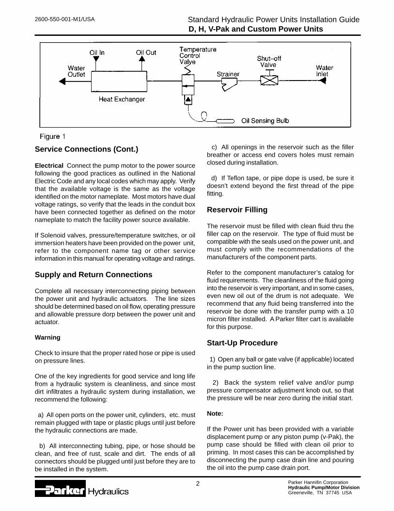
Water (If water cooled heat exchange has beenprovided) Connect the water supply to the inlet of theheat exchanger, with a shut-off valve and strainer (ifnot supplied by Parker). If a temperature Control Valve(Model WTC**) has been provided, it also should beinstalled on the inlet side. The outlet of the heatexchanger should be connected directly to the facilitydrain system. On single pass heat exchangers the waterconnections should be installed as shown below. Onmulti-pass heat exchanger the water flow direction isnot important. (See fig. 1)
1
Parker Hannifin CorporationHydraulic Pump/Motor DivisionGreeneville, TN 37745 USA
2600-550-001-M1/USA Standard Hydraulic Power Units Installation GuideD, H, V-Pak and Custom Power Units
Service Connections (Cont.)
Electrical Connect the pump motor to the power sourcefollowing the good practices as outlined in the NationalElectric Code and any local codes which may apply. Verifythat the available voltage is the same as the voltageidentified on the motor nameplate. Most motors have dualvoltage ratings, so verify that the leads in the conduit boxhave been connected together as defined on the motornameplate to match the facility power source available.
If Solenoid valves, pressure/temperature switches, or oilimmersion heaters have been provided on the power unit,refer to the component name tag or other serviceinformation in this manual for operating voltage and ratings.
Supply and Return Connections
Complete all necessary interconnecting piping betweenthe power unit and hydraulic actuators. The line sizesshould be determined based on oil flow, operating pressureand allowable pressure dorp between the power unit andactuator.
Warning
Check to insure that the proper rated hose or pipe is usedon pressure lines.
One of the key ingredients for good service and long lifefrom a hydraulic system is cleanliness, and since mostdirt infiltrates a hydraulic system during installation, werecommend the following:
a) All open ports on the power unit, cylinders, etc. mustremain plugged with tape or plastic plugs until just beforethe hydraulic connections are made.
b) All interconnecting tubing, pipe, or hose should beclean, and free of rust, scale and dirt. The ends of allconnectors should be plugged until just before they are tobe installed in the system.
c) All openings in the reservoir such as the fillerbreather or access end covers holes must remainclosed during installation.
d) If Teflon tape, or pipe dope is used, be sure itdoesn’t extend beyond the first thread of the pipefitting.
Reservoir Filling
The reservoir must be filled with clean fluid thru thefiller cap on the reservoir. The type of fluid must becompatible with the seals used on the power unit, andmust comply with the recommendations of themanufacturers of the component parts.
Refer to the component manufacturer’s catalog forfluid requirements. The cleanliness of the fluid goinginto the reservoir is very important, and in some cases,even new oil out of the drum is not adequate. Werecommend that any fluid being transferred into thereservoir be done with the transfer pump with a 10micron filter installed. A Parker filter cart is availablefor this purpose.
Start-Up Procedure
1) Open any ball or gate valve (if applicable) locatedin the pump suction line.
2) Back the system relief valve and/or pumppressure compensator adjustment knob out, so thatthe pressure will be near zero during the initial start.
Note:
If the Power unit has been provided with a variabledisplacement pump or any piston pump (v-Pak), thepump case should be filled with clean oil prior topriming. In most cases this can be accomplished bydisconnecting the pump case drain line and pouringthe oil into the pump case drain port.
2
Parker Hannifin CorporationHydraulic Pump/Motor DivisionGreeneville, TN 37745 USA
2600-550-001-M1/USA Standard Hydraulic Power Units Installation GuideD, H, V-Pak and Custom Power Units
Start-up Procedure (Cont.)
3) If the system has been provided with an open centerdirectional valve, the oil during start-up will flow directlyback to tank. If the system has a closed center valve, itmay be necessary to loosen a fitting momentarily at thepump discharge, to bleed any air in the pump during thepriming operation.
4) Jog the pump motor once, and verify that the pump isrotating in the same direction as the arrow tag on the pumpcase. If the direction is incorrect, reverse two (2) of thethree (3) motor leads, and recheck the rotation.
5) Jog the pump/motor (3) to (6) times to prime the pumpand allow the pump to run for several minutes at zeropressure. Check the piping for any leaks and correctimmediately. (Leaks in fittings and tubing can be the resultof vibration during shipping.)
6) Begin adjusting the relief valve and /or pumpcompensator to increase the pressure gradually. Note:on systems with open center directional valves, it will benecessary to actuate the valve to build pressure.
7) Continue increasing pressure until normal operatingpressure is obtained, and recheck system for leaks. Lockadjustment screws in place.
NoteIf the system has been provided with a pressurecompensator pump and a relief valve, adjust the reliefvalve approximately 200 PSI higher than the compensatorso that excessive heat is not generated by the relief valve.
8) During the start-up sequence, all filters should bemonitored closely. Replace any filters elementimmediately, as soon as they begin to go into by-pass asindicated on the visual indicator.
9) After the entire system has been wetted with fluid,refill the reservoir to the normal operating level.
10) Verify that the cooling water to the heat exchanger(if applicable) is flowing. If the power unit has beenprovided with a water control valve (Model WTC**), andthe oil temperature is exceeding 135°F, adjust the valveto increase the water flow.
Special Tools
All normal service and maintenance on standard powerunits can be accomplished with standard hand tools. Nospecial tools are required.
General Maintenance
Electric Motors – Lubricate as recommended by themotor manufacturer.
Filters – Change or clean as required or as indicated onfilters supplied with visual indicators. Make sure to checkindicators shortly after start-up.
Suction Strainers – Should be cleaned after 10 hours ofoperation initially and every 100 hours thereafter. Seeappendices for cleaning instructions.
Reservoirs - Maintain oil level at all times. The oil shouldbe checked after the first 100 hours and verify that theclass of oil meets the requirements of the pump beingused. Change the oil every 1000 to 2000 hours dependingon the application and operation environment.
Comments – See component literature in appendices.
Recommended Spare Parts
Spare filter elements should be purchased with the powerunit, and be available during the start-up operation. Otherspare parts may be required, and are a function of theduty cycle of the hydraulic system, operation environment,and the acceptable down time of the equipment.
Preventive Maintenance
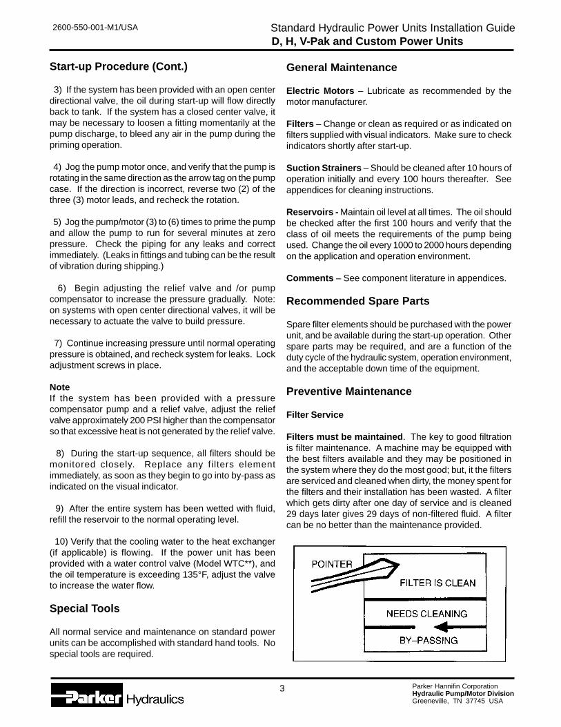
Filter Service
Filters must be maintained. The key to good filtrationis filter maintenance. A machine may be equipped withthe best filters available and they may be positioned inthe system where they do the most good; but, it the filtersare serviced and cleaned when dirty, the money spent forthe filters and their installation has been wasted. A filterwhich gets dirty after one day of service and is cleaned29 days later gives 29 days of non-filtered fluid. A filtercan be no better than the maintenance provided.
3
Parker Hannifin CorporationHydraulic Pump/Motor DivisionGreeneville, TN 37745 USA
2600-550-001-M1/USA Standard Hydraulic Power Units Installation GuideD, H, V-Pak and Custom Power Units
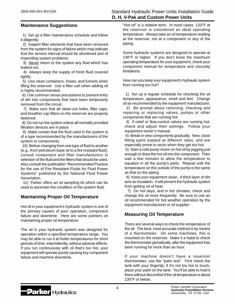
Maintenance Suggestions
1) Set up a filter maintenance schedule and followit diligently. 2) Inspect filter elements that have been removedfrom the system for signs of failure which may indicatethat the service interval should be shortened and ofimpending system problems. 3) Never return to the system any fluid which hasleaked out. 4) Always keep the supply of fresh fluid coveredtightly. 5) Use clean containers, hoses, and funnels whenfilling the reservoir. Use a filter cart when adding oilis highly recommended. 6) Use common sense precautions to prevent entryof dirt into components that have been temporarilyremoved from the circuit. 7) Make sure that all clean-out holes, filter caps,and breather cap filters on the reservoir are properlyfastened. 8) Do not run the system unless all normally providedfiltration devices are in place. 9) Make certain that the fluid used in the system isof a type recommended by the manufacturers of thesystem or components. 10) Before changing from one type of fluid to another(e.g., from petroleum base oil to a fire resistant fluid),consult component and filter manufacturers inselection of the fluid and the filters that should be used.Also consult the publication “Recommended Practicefor the use of Fire Resistant Fluids for Fluid PowerSystems” published by the National Fluid PowerAssociation. 11) Parker offers an oil sampling kit which can beused to ascertain the condition of the system fluid.
Maintaining Proper Oil Temperature
Hot oil in your equipment’s hydraulic system is one ofthe primary causes of poor operation, componentfailure and downtime. Here are some pointers onmaintaining proper oil temperature.
The oil in your hydraulic system was designed foroperation within a specified temperature range. Youmay be able to run it at hotter temperatures for shortperiods of time, intermittently, without adverse effects.If you run continuously with oil that’s too hot, yourequipment will operate poorly causing key componentfailure and machine downtime.
“Hot oil” is a relative term. In most cases, 120°F atthe reservoir is considered an ideal operatingtemperature. Always take an oil temperature readingat the reservoir, not at a component or any of thepiping.
Some hydraulic systems are designed to operate at130°F or higher. If you don’t know the maximumoperating temperature for your equipment, check yourcomponent manual for temperature and viscositylimitations.
How can you keep your equipment’s hydraulic systemfrom running too hot?
1) Set up a regular schedule for checking the oiltemperature, appearance, smell and feel. Changeoil as recommended by the equipment manufacturer. 2) Be prompt about removing, checking andrepairing or replacing valves, pumps or othercomponents that are running hot. 3) If relief or flow-control valves are running hot,check and adjust their settings. Follow yourequipment owner’s manual. 4) Break in new components gradually. New, closefitting parts expand at different rates, and areespecially prone to seize when they get too hot. 5) Start a cold pump motor on hot oil by jogging justenough to draw the hot oil into the component. Thenwait a few minutes to allow the temperature toequalize in all the pump’s parts. Repeat until thetemperature on the outside of the pump is the sameas that on the piping. 6) Keep your equipment clean. A thick layer of dirtacts as insulation. It will prevent the hydraulic systemfrom getting rid of heat. 7) On hot days, and in hot climates, check andchange the oil more frequently. Be sure to use anoil recommended for hot weather operation by theequipment manufacturer or oil supplier.
Measuring Oil Temperature
There are several ways to check the temperature ofthe oil. The best, most accurate method is by meansof a thermometer. On some machines, this ismounted on the reservoir. Make it a habit to checkthe thermometer periodically, after the equipment hasbeen running for more than an hour.
If your machine doesn’t have a reservoirthermometer, use the “palm test”. First check thetank with your fingertip; if it’s not too hot to touch,place your palm on the tank. You’ll be able to hold itthere without discomfort if the oil temperature is about130°F or below.
4
Parker Hannifin CorporationHydraulic Pump/Motor DivisionGreeneville, TN 37745 USA
2600-550-001-M1/USA Standard Hydraulic Power Units Installation GuideD, H, V-Pak and Custom Power Units
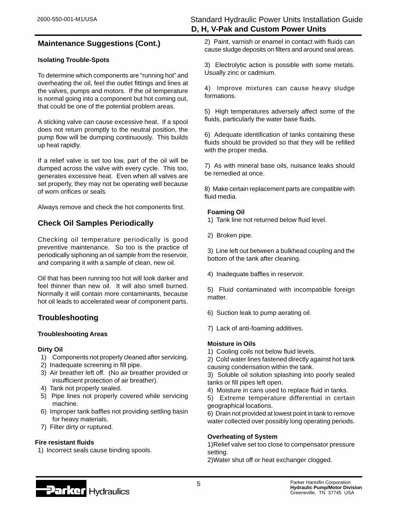
Maintenance Suggestions (Cont.)
Isolating Trouble-Spots
To determine which components are “running hot” andoverheating the oil, feel the outlet fittings and lines atthe valves, pumps and motors. If the oil temperatureis normal going into a component but hot coming out,that could be one of the potential problem areas.
A sticking valve can cause excessive heat. If a spooldoes not return promptly to the neutral position, thepump flow will be dumping continuously. This buildsup heat rapidly.
If a relief valve is set too low, part of the oil will bedumped across the valve with every cycle. This too,generates excessive heat. Even when all valves areset properly, they may not be operating well becauseof worn orifices or seals.
Always remove and check the hot components first.
Check Oil Samples Periodically
Checking oil temperature periodically is goodpreventive maintenance. So too is the practice ofperiodically siphoning an oil sample from the reservoir,and comparing it with a sample of clean, new oil.
Oil that has been running too hot will look darker andfeel thinner than new oil. It will also smell burned.Normally it will contain more contaminants, becausehot oil leads to accelerated wear of component parts.
Troubleshooting
Troubleshooting Areas
Dirty Oil1) Components not properly cleaned after servicing.2) Inadequate screening in fill pipe.3) Air breather left off. (No air breather provided or
insufficient protection of air breather).4) Tank not properly sealed.5) Pipe lines not properly covered while servicing
machine.6) Improper tank baffles not providing settling basin
for heavy materials.7) Filter dirty or ruptured.
Fire resistant fluids1) Incorrect seals cause binding spools.
2) Paint, varnish or enamel in contact with fluids cancause sludge deposits on filters and around seal areas.
3) Electrolytic action is possible with some metals.Usually zinc or cadmium.
4) Improve mixtures can cause heavy sludgeformations.
5) High temperatures adversely affect some of thefluids, particularly the water base fluids.
6) Adequate identification of tanks containing thesefluids should be provided so that they will be refilledwith the proper media.
7) As with mineral base oils, nuisance leaks shouldbe remedied at once.
8) Make certain replacement parts are compatible withfluid media.
Foaming Oil1) Tank line not returned below fluid level.
2) Broken pipe.
3) Line left out between a bulkhead coupling and thebottom of the tank after cleaning.
4) Inadequate baffles in reservoir.
5) Fluid contaminated with incompatible foreignmatter.
6) Suction leak to pump aerating oil.
7) Lack of anti-foaming additives.
Moisture in Oils1) Cooling coils not below fluid levels.2) Cold water lines fastened directly against hot tankcausing condensation within the tank.3) Soluble oil solution splashing into poorly sealedtanks or fill pipes left open.4) Moisture in cans used to replace fluid in tanks.5) Extreme temperature differential in certaingeographical locations.6) Drain not provided at lowest point in tank to removewater collected over possibly long operating periods.
Overheating of System1)Relief valve set too close to compensator pressuresetting.2)Water shut off or heat exchanger clogged.
5
Parker Hannifin CorporationHydraulic Pump/Motor DivisionGreeneville, TN 37745 USA
2600-550-001-M1/USA Standard Hydraulic Power Units Installation GuideD, H, V-Pak and Custom Power Units
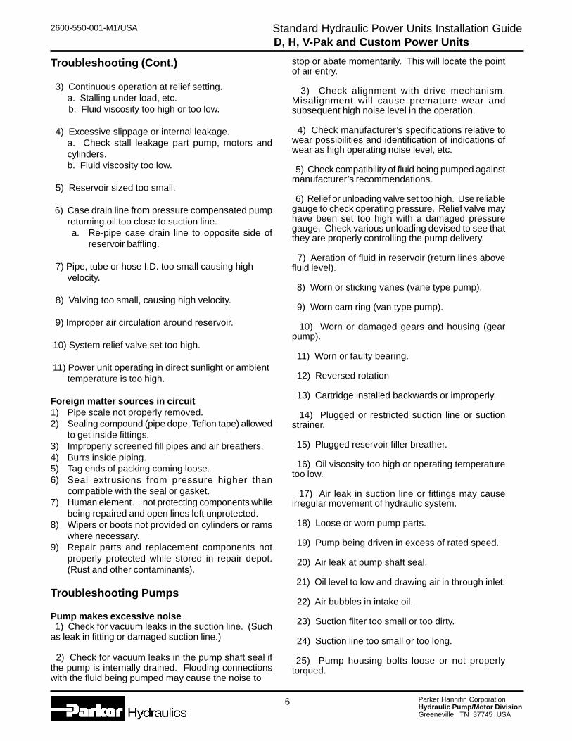
Troubleshooting (Cont.)
3) Continuous operation at relief setting.a. Stalling under load, etc. b. Fluid viscosity too high or too low.
4) Excessive slippage or internal leakage.a. Check stall leakage part pump, motors andcylinders.b. Fluid viscosity too low.
5) Reservoir sized too small.
6) Case drain line from pressure compensated pumpreturning oil too close to suction line.a. Re-pipe case drain line to opposite side of
reservoir baffling.
7) Pipe, tube or hose I.D. too small causing highvelocity.
8) Valving too small, causing high velocity.
9) Improper air circulation around reservoir.
10) System relief valve set too high.
11) Power unit operating in direct sunlight or ambienttemperature is too high.
Foreign matter sources in circuit1) Pipe scale not properly removed.2) Sealing compound (pipe dope, Teflon tape) allowed
to get inside fittings.3) Improperly screened fill pipes and air breathers.4) Burrs inside piping.5) Tag ends of packing coming loose.6) Seal extrusions from pressure higher than
compatible with the seal or gasket.7) Human element… not protecting components while
being repaired and open lines left unprotected.8) Wipers or boots not provided on cylinders or rams
where necessary.9) Repair parts and replacement components not
properly protected while stored in repair depot.(Rust and other contaminants).
Troubleshooting Pumps
Pump makes excessive noise 1) Check for vacuum leaks in the suction line. (Suchas leak in fitting or damaged suction line.)
2) Check for vacuum leaks in the pump shaft seal ifthe pump is internally drained. Flooding connectionswith the fluid being pumped may cause the noise to
stop or abate momentarily. This will locate the pointof air entry.
3) Check alignment with drive mechanism.Misalignment will cause premature wear andsubsequent high noise level in the operation.
4) Check manufacturer’s specifications relative towear possibilities and identification of indications ofwear as high operating noise level, etc.
5) Check compatibility of fluid being pumped againstmanufacturer’s recommendations.
6) Relief or unloading valve set too high. Use reliablegauge to check operating pressure. Relief valve mayhave been set too high with a damaged pressuregauge. Check various unloading devised to see thatthey are properly controlling the pump delivery.
7) Aeration of fluid in reservoir (return lines abovefluid level).
8) Worn or sticking vanes (vane type pump).
9) Worn cam ring (van type pump).
10) Worn or damaged gears and housing (gearpump).
11) Worn or faulty bearing.
12) Reversed rotation
13) Cartridge installed backwards or improperly.
14) Plugged or restricted suction line or suctionstrainer.
15) Plugged reservoir filler breather.
16) Oil viscosity too high or operating temperaturetoo low.
17) Air leak in suction line or fittings may causeirregular movement of hydraulic system.
18) Loose or worn pump parts.
19) Pump being driven in excess of rated speed.
20) Air leak at pump shaft seal.
21) Oil level to low and drawing air in through inlet.
22) Air bubbles in intake oil.
23) Suction filter too small or too dirty.
24) Suction line too small or too long.
25) Pump housing bolts loose or not properlytorqued.
6

Parker Hannifin CorporationHydraulic Pump/Motor DivisionGreeneville, TN 37745 USA
2600-550-001-M1/USA Standard Hydraulic Power Units Installation GuideD, H, V-Pak and Custom Power Units
Troubleshooting Pumps (Cont.)
Pump failure to delivery fluid1) Low fluid level in reservoir.
2) Oil intake pipe suction strainer plugged. 3) Air leak in suction line and preventing priming. 4) Pump shaft turning too slowly. 5) Oil viscosity too high. 6) Oil lift too high. 7) Wrong shaft rotation. 8) Pump shaft or parts broken. 9) Dirt in pump. 10) Variable delivery pumps (improper stroke).
Oil leakage around pump1) Shaft seal worn.
2) Head of oil on suction pipe connection – connectionleaking
3) Pump housing bolts loose or improperly torqued.
4) Case drain line too small or restricted (shaft sealleaking).
Excessive pump wear 1) Abrasive dirt in the hydraulic oil being circulatedthrough the system.
2) Oil viscosity too low.
3) System pressure exceeds pump rating.
4) Pump misalignment or belt drive too tight.
5) Air being drawn in through inlet of pump.
Pump parts inside housing broken 1) Seizure due to lack of oil.
2) Excessive system pressure above maximum pumprating.
3) Excessive torquing of housing bolts.
4) Solid matter being drawn in from reservoir andwedged in pump.
Troubleshooting Solenoid Valves
Solenoid failures 1) Voltage too low. If voltage is not sufficient tocomplete the stroke of the solenoid, it will burn out thecoil.
2) Voltage too high. Excessive voltage can also burnout coils.
3) Signal to both solenoids of a double solenoid valvesimultaneously. One or both of the solenoids will beunable to complete their stroke and will burn out. (Makecertain the electrical signal is interlocked so that thiscondition cannot exist).
4) Mechanical damage to leads. (Short circuit, openconnections, etc.)
5) Tight spool or other mechanical parts of the valvebeing actuated can prevent the solenoid from completingits stroke and subsequently burning out.
6) Replacement springs too heavy in valve. Overloadssolenoid and shortens life.
7) Dirty contacts may not supply sufficient current tosolenoid to satisfy inrush demands.
8) Low voltage direct current solenoids may beaffected by low battery capacity on cold morningsdirectly after starting cold engine. (DC)
9) Long feed lines to low voltage solenoids may causesufficient voltage drop to cause erratic operation.
Solenoid valve fails to operate 1) Is there an electrical signal to the solenoid oroperating device? Is the voltage too low? (Check withvoltmeter…test light in emergency.)
2) If the supply to the pilot body is orificed, is the orificerestricted? (Remove orifice and check for foreign matter.Flushing is sometimes necessary because of floatingimpediment.)
3) Has foreign matter jammed the main spool?(Remove end caps and see that main spool is free in itsmovement…remember that there will be a quantity offluid escaping when the cap is removed and provide acontainer to catch it.)
4) Is pilot pressure available? Is the pilot pressureadequate? (Check with gauge on main pressure inputport for internally piloted types and in the supply line tothe externally piloted type.)
5) Is pilot drain restricted? (Remove pilot drain andlet the fluid pour into an open container while themachine is again tried for normal operation. Small linesare often crushed by machine parts banging againstthem causing a subsequent restriction to fluid flow.)
7
Parker Hannifin CorporationHydraulic Pump/Motor DivisionGreeneville, TN 37745 USA
2600-550-001-M1/USA Standard Hydraulic Power Units Installation GuideD, H, V-Pak and Custom Power Units
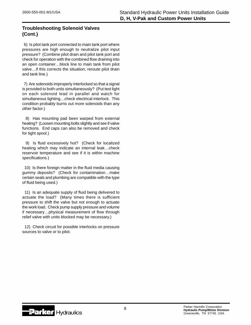
Troubleshooting Solenoid Valves(Cont.)
6) Is pilot tank port connected to main tank port wherepressures are high enough to neutralize pilot inputpressure? (Combine pilot drain and pilot tank port andcheck for operation with the combined flow draining intoan open container…block line to main tank from pilotvalve…if this corrects the situation, reroute pilot drainand tank line.)
7) Are solenoids improperly interlocked so that a signalis provided to both units simultaneously? (Put test lighton each solenoid lead in parallel and watch forsimultaneous lighting…check electrical interlock. Thiscondition probably burns out more solenoids than anyother factor.)
8) Has mounting pad been warped from externalheating? (Loosen mounting bolts slightly and see if valvefunctions. End caps can also be removed and checkfor tight spool.)
9) Is fluid excessively hot? (Check for localizedheating which may indicate an internal leak…checkreservoir temperature and see if it is within machinespecifications.)
10) Is there foreign matter in the fluid media causinggummy deposits? (Check for contamination…makecertain seals and plumbing are compatible with the typeof fluid being used.)
11) Is an adequate supply of fluid being delivered toactuate the load? (Many times there is sufficientpressure to shift the valve but not enough to actuatethe work load. Check pump supply pressure and volumeif necessary…physical measurement of flow throughrelief valve with units blocked may be necessary.)
12) Check circuit for possible interlocks on pressuresources to valve or to pilot.
8
Parker Hannifin CorporationHydraulic Pump/Motor DivisionGreeneville, TN 37745 USA
2600-550-001-M1/USA Standard Hydraulic Power Units Installation GuideD, H, V-Pak and Custom Power Units

Parker Hannifin CorporationHydraulic Pump/Motor Division2745 Snapps Ferry RoadGreeneville, TN 37745 USATel (423) 639-8151Fax (423) 787-2418Web Site: www.parker.com/pumpmotor
Pinnacle Printing, 10/2000, 5M
Hydraulics