staffing requirements for future small and medium reactors
TRANSCRIPT

IAEA-TECDOC-1193
Staffing requirements for future small and medium reactors (SMRs)
based on operating experience and projections
January 2001

The originating Section of this publication in the IAEA was:
Nuclear Power Technology Development Section International Atomic Energy Agency
Wagramer Strasse 5 P.O. Box 100
A-1400 Vienna, Austria
STAFFING REQUIREMENTS FOR FUTURE SMALL AND MEDIUM REACTORS (SMRs) BASED ON OPERATING EXPERIENCE AND PROJECTIONS
IAEA, VIENNA, 2001 IAEA-TECDOC-1193
ISSN 1011–4289
© IAEA, 2001
Printed by the IAEA in Austria January 2001

FOREWORD
At the time of this study there were about 160 small and medium sized nuclear power
reactors (referred to as SMRs) in operation worldwide, and about 25 more under construction.
Operation and maintenance costs for operating SMRs represent a substantial portion of the
cost of electricity produced. Of these costs, the direct and indirect cost of staff represents the
major cost component.
In recent years, particularly since 1990, there has been increased interest in SMRs by
many developing countries wishing to take advantage of nuclear power and several small and
medium reactor designs are in various stages of development. To enhance the economic
competitive position of SMRs relative to alternative methods of electricity generation, it is
essential to ensure that new SMRs can be operated reliably and efficiently using the optimum
number of staff.
This publication reviews the lessons learned from the reactor operation, and the insights
gained through the design of new SMRs, with a view to optimizing staffing in order to
improve overall plant economics without compromising safety.
This publication is intended to evaluate the estimated staffing size of various SMRs, the
staff qualification and training required for the operation of future SMRs, and the key issues
which impact the staffing requirements that should be considered in the development and
deployment of future SMRs.
The IAEA officer responsible for this publication was B.O. Cho of the Division of
Nuclear Power.

EDITORIAL NOTE
This publication has been prepared from the original material as submitted by the authors. The views
expressed do not necessarily reflect those of the IAEA, the governments of the nominating Member
States or the nominating organizations.
The use of particular designations of countries or territories does not imply any judgement by the
publisher, the IAEA, as to the legal status of such countries or territories, of their authorities and
institutions or of the delimitation of their boundaries.
The mention of names of specific companies or products (whether or not indicated as registered) does
not imply any intention to infringe proprietary rights, nor should it be construed as an endorsement
or recommendation on the part of the IAEA.
The authors are responsible for having obtained the necessary permission for the IAEA to reproduce,
translate or use material from sources already protected by copyrights.

CONTENTS
1. INTRODUCTION ....................................................................................................................... 1
2. UTILITY EXPERIENCE WITH STAFFING OF NUCLEAR POWER PLANTS ............... 2
2.1. Organisation and staffing..................................................................................................... 2
2.2. Experience and strategies to optimise staffing .................................................................... 2
2.2.1. Manpower qualification and training ........................................................................ 4
2.2.2. Work activity efficiency improvement ...................................................................... 4
2.2.3. Surveillance and in-service inspection processes ...................................................... 6
2.3. Institutional factors and issues which influence staffing ..................................................... 6
3. PROJECTED STAFFING REQUIREMENTS FOR FUTURE SMR DESIGNS.................. 7
3.1. Overview of current status of new SMR designs ................................................................ 7
3.2. Design and operating features of future SMR plants to optimise plant staffing.................. 7
3.2.1. General ...................................................................................................................... 7
3.3. Estimated number of staff required to operate new SMRs................................................ 13
3.3.1. General .................................................................................................................... 13
3.3.2. Estimated staff levels for new SMRs ...................................................................... 14
3.3.3. Observations ............................................................................................................ 15
3.4. Recommendations on staff qualifications and training required for future SMRs............ 16
3.5. Staffing requirements of SMRs from the developing country point of view .................... 17
3.5.1. Major concerns in developing countries.................................................................. 17
3.5.2. Recommendations to the developing countries ....................................................... 18
4. CONCLUSIONS .................................................................................................................. 19
APPENDIX: STATUS OF SMRS UNDER DEVELOPMENT .............................................. 21
ANNEX
Staffing requirements for future small & medium reactors .......................................................... 25
D. McQuade Development prospects for future small and medium reactors (SMRs)....................................... 41
Jianchi Huang Experiences and lessons learnt on staffing from the first
Indian nuclear power plant (PHWR) ................................................................................... 47
A.S. Bhattacharya, V.S. Bhavan Influence of design improvements in optimising staffing
of NPPs — An Indian experience........................................................................................ 59
A.S. Bhattacharya, V.S. Bhavan Staffing requirements for SMRs: The South African view........................................................... 67
W. Roscoe Staff size evolution at the Spanish nuclear power plants .............................................................. 75
M. Ibañez Organizational development at Forsmark NPP............................................................................. 81
H. Metzén

Staffing and training experience at the Bilibino nuclear power plant........................................... 85
F. Tukhvetov Staffing requirements for future small and medium reactors based on
projections in the Russian Federation.................................................................................. 89
G.M. Antonovsky, N.G. Kodochigov, A.V. Kurachenkov, V.V. Novikov Manning designs for nuclear district-heating plant (NDHP) with RUTA-type reactor ............... 95
V.S. Gerasimova, V.I.Mikhan, À.A.Romenkov Improvements in nuclear plant staffing resulting from the AP-600 design programme ............ 103
C. Mycoff Design studies on staffing requirements for the new generation nuclear power units of
WWER-640 and BN-800 reactor-types............................................................................. 113
D.F. Solovyov
List of Participants ....................................................................................................................... 123

1
1. INTRODUCTION
About 8500 reactor-years of operating experience have been accumulated with nuclear
power plants (NPPs). Most nuclear power is generated in industrialized countries, but a
number of developing countries have also deployed nuclear power plants. In most developing
countries the unit size has been mainly in the small and medium reactor (SMR) size range.
According to the IAEA-TECDOC-999 "Introduction of Small and Medium Reactors in
Developing Countries", about 160 SMRs are in operation and about 25 more are under
construction. The design and development effort on SMRs has significantly increased since
1990 and new designs have been presented over the last years.
The most significant component of operation and maintenance (O&M) cost in the SMRs
is the direct and indirect cost of personnel; it is therefore essential for the operators of SMRs
to improve the efficiency and effectiveness of their organizational structures and staffing in
order to maintain the economic viability of their plants. The designers of new SMRs must
strive to improve the maintainability and operational characteristics in order to achieve the
more effective use of staff and improve overall plant economics and performance.
This publication has been prepared in response to the recommendation of developing
countries having an interest in SMRs, and describes current SMR experience with regard to
staffing and the projected staffing requirements for future SMR designs.
The primary purposes of this publication are to:
�� Document the lessons learned from reactor operation, and the insights gained through the
design of new SMRs, with a view to optimizing staffing in order to improve overall plant
economics without compromising safety;
�� Evaluate the estimated staffing size of various SMRs, including a comparison between
operating SMRs and the new SMR designs proposed;
�� Identify the staff qualification and training required for the operation of new SMRs,
especially in developing countries that are contemplating implementation of SMRs;
�� Identify the key issues that impact the staffing requirements and should be considered in
the development and deployment of future SMRs.
Although focused on SMRs, many of the comments in this publication are applicable to
all NPPs.
The target audiences for this publication include:
�� Reactor designers and reactor operators who are incorporating the feedback of reactor
operation experience into SMRs that are currently operating,
�� Utilities that are planning to upgrade their plant systems to enhance human factors and take
advantage of advanced technologies,
�� Designers of new SMRs,
�� Utilities who are initiating a new nuclear power programme, based on SMRs, especially in
developing countries.
Reference material for this publication includes the staffing status and trends reported
for various types of reactors, the relevant IAEA technical documents, and the staff
requirement projections of the designers of new SMRs. To project the staffing requirements

2
for SMRs, i.e. reactors up to about 700 MW(e) in capacity that are designed for electricity
generation or cogeneration of heat and electricity are considered.
This report is organized into four sections. This section (Section 1) provides the
framework for the report. Section 2 describes the experience of staff management gained by
operators of nuclear power plants. Section 3 describes the design improvements for future
SMRs and the expectations of staffing requirements and Section 4 summarizes the
conclusions. The Annex contains selected papers presented during the relevant Advisory
Group Meeting and the consultants meetings.
2. UTILITY EXPERIENCE WITH STAFFING OF NUCLEAR POWER PLANTS
Experience demonstrates that a complex relationship exists between staffing costs and
plant performance. The available information proves that if staff numbers are reduced below
the optimum, level, a negative impact on the capacity factor will occur, with a resulting
increase in specific electricity generation costs, and in extreme cases, in the shutdown of the
nuclear plant. However, the available information also shows that the provision of large staff
levels does not ensure economic or reliable SMR operation. Operating plants that have
maintained high capacity factors with relatively low staffing number are characterized by
having very mature and experienced staff.
The most important factor contributing to low electricity generation cost in all nuclear
power plants is the capacity factor that is achieved during long term operation. A highly
effective preventative maintenance and inspection programme and a well documented
operating regime is necessary in order to achieve high capacity factors over the plant operating
life. These measures serve to minimise unplanned tasks and outages. In the long term, the
implementation of efficient well-defined maintenance, inspection and operating processes
reduce the required staff level. An optimum staffing plan assures that qualified staff are
available when needed, provide opportunities for gaining on-the-job experience, and avoids
the involvement of excess people and the resultant additional risk of human error.
2.1. Organisation and staffing
Staffing data from 54 plants in 19 countries is presented in IAEA-TECDOC-1052
“Nuclear Power Plant Organization and Staffing to Improve Performance: Lessons Learned”.
This data shows average staffing levels of approximately one person per MW(e) for a large
single unit plant. For small units the specific staffing level tends to increase to about 1.5
person/MW(e), while stations with several large units reduce the specific staffing level to
approximately 0.7 person/MW(e). Staffing numbers from various countries are shown in the
papers of Appendix B. This includes actual staffing from operating plants as well as
projections for future SMRs.
IAEA Safety Series No. 50-SG-O1 (Rev.1) “Staffing of Nuclear Power Plants and the
Recruitment, Training and Authorization of Operating Personnel” defines the factors to be
considered to ensure optimal staffing along with examples of nuclear power plant
organizational structures and terminology.
2.2. Experience and strategies to optimise staffing
Optimised staffing is necessary to ensure high performance with regards to safety and
economics of all NPPs. Optimising does not necessarily mean having a very low number of

3
employees, nor does it mean maintaining a fixed number over time. The number of staff
should be adequate to perform all the required tasks at the site in an efficient, competent and
safe manner. This permanent staff number should refer to fully qualified employees (and
contractors) assuming a zero staff turnover rate. Planning for the anticipated staff turnover
should provide for staff undergoing training and should be shown in addition to the permanent
staff complement.
Optimising staff level should include optimising the workload and schedules for both
routine and non-routine activities, the proper human engineering of work areas and work
processes, comprehensive planning, the provision of well defined work packages, and the
provision of all tools and equipment necessary to efficiently accomplish the tasks.
Strategies to assure optimum staff levels include those listed below:
�� Management layers should be minimised where possible. The number of persons reporting
to each manager is recommended to be between 5 and 12;
�� The organisation should be formed according to local rules prevailing at the time These
rules could include requirements from the regulators, organisation working rules, union
agreements, and salary policies. The use of contractors may vary due to many factors,
including the size of the utility, the number of nuclear units operated, the expertise of the
utility, and local conditions. In this publication the use of contractors is foreseen only for
short-term tasks (for example, during outages) and when specialist competence is required;
�� An effective training and staff development programme is required to assure the
availability of suitably trained and qualified staff; the staff development programme should
provide for the maintenance and upgrading of the skills of the plant staff, and for the
qualification of new staff. It is important to clearly define responsibilities and interfaces
between departments. Good communication should be established;
�� Low staff turnover rate is essential for establishing an effective organisation. This may be
achieved by making the working conditions at the site attractive to the employees.
The organisation should be flexible and able to meet changing demands. During
commissioning and the first years of operation the work load at the site may be high due to the
many activities taking place; for example, establishing procedures, establishing work
processes, completing inaugural inspections, and the training of staff. Assistance from the
vendor and other qualified contractors should be considered during this time period.
The use of self-managed multi-disciplinary teams is recommended to increase work
efficiency. However, this process must be supplemented by the development of individual
specialists in designated fields. Individuals should also be provided with the opportunities to
develop analytical and managerial skills. Management should ensure that all personnel are
trained and qualified for effective job performance; this must include management and
supervisory development. The performance of the plant will reflect the performance and
competence of the staff. The IAEA Technical Reports Series No. 369 “Management for
Excellence in Nuclear Power Plant Performance” contains useful direction in the many and
various aspects of the management of nuclear power plants.
Multi-discipline knowledge should be encouraged to enhance the understanding of how
each task influences other parts of the organisation; this also serves to create a good
communications environment.
Benchmarking is a tool used to, amongst other things, identify effective organisation and
work methods, and to thereby optimise staffing levels; however, other methodologies for
analysing the effectiveness of the present organisation and staffing levels should also be used.

4
The effectiveness of the work processes may be improved by the use of modern
information technology (IT) systems. It is important that all functions at the site use the same
IT tools and a common database. The supplier should provide input for a component database,
including the plant technical description and component specifications, including references to
technical documentation, drawings and plant coding.
Early definition of the utility organisational structure is necessary; of particular
importance is the allocation of functions/tasks between the site and the corporate offices.
Implementation of a comprehensive human factor programme in all aspects of plant
operation and maintenance design and training should be used to minimise the potential for
human error; this programme should include building the proper employee attitudes, training
employees to introduce a self-check attitude, and to function in a teamwork environment.
Other elements include establishing effective routines and procedures to enhance efficiency of
work process, and creating “ownership” of assigned functions.
The psychological evaluation of control room staff and senior operators should be
considered in order to assure their compatibility with their often-stressful responsibilities.
2.2.1. Manpower qualification and training
Generic requirements for the qualification and training of staff are identified in IAEA
Safety Series No. 50-SG-O1 (Rev.1) “Staffing of Nuclear Power Plants and the Recruitment,
Training and Authorization of Operating Personnel”.
Measures to assure staff qualification may include:
�� Systematic competency analysis for each job including licensed positions should provide
the basis for defining training requirements and logistics development,
�� Job rotation, promoting multi-skills qualification, are of advantage to the optimisation of
the number of staff; however job rotation should not be imposed to the extent that if
detracts from “task ownership”,
�� Specialisation in certain key skills is necessary to provide competent and efficient
operation; contractors can be efficiently utilised for many specialised tasks by small
utilities,
�� Workers should be trained for radiation and personal safety, to assure that all required
safety requirements are routinely satisfied.
Standards for entry-level qualifications and tests assure that recruited personnel can be
qualified for the jobs in the planned time frame. The base entry requirements for specific staff
on many existing SMRs are increasing. Development of an integrated training infrastructure,
encompassing on-the-job training, qualified trainers, training materials, and training tools such
as simulators and facility mock-ups for developing skills should be given priority.
Creation of a common vision between management, plant operations staff, and plant
maintenance and inspection staff, by focusing on the inter-linking roles they play towards
sustaining high performance is important.
2.2.2. Work activity efficiency improvement
Substantial increases in work activity efficiency are often available that reduce
maintenance workload. Key elements include the improvement of plant maintainability
through the provision of enhanced support systems (for example permanent or mobile

5
scaffolding and easy access to services such as electricity, service air, and breathing air, at all
required locations). Further improvements may result from well-defined and standardised
working procedures, and simplified work authorisation processes.
Establishing clear and effective ground rules for the estimation, planning, and
scheduling of all work including preventive and corrective maintenance, component
surveillance, and component calibration, will contribute to the formulation of optimised
staffing requirements.
The optimisation of the spare parts inventory is essential to minimising maintenance
delays. In some cases, contracts with suppliers and/or other utilities may provide for fast
delivery of spares as required; this approach is particularly valid for spares that are rarely
required. In some cases additional on-site specialised support for the fabrication of spares,
motor rewinding, etc. may be justified; this increases staff requirements in most cases. A
comprehensive assessment of available vendor and component supplier support must be
completed at an early stage of plant operation and maintained during the plant life in order to
optimise spare parts and specialised staff requirements.
Maintenance planning and preparation must be comprehensive in order to ensure the
timely availability of materials, tools, safety equipment, permits, procedures, shop facilities,
and systems and equipment isolation approvals. This is most easily achieved if a large fraction
of the maintenance required is preventative rather than corrective. Many SMR operators
begin outage planning a year or more ahead of the outage date. Failure to adequately plan
maintenance activities will have a negative impact on productivity and will lead to increased
staffing level demands and a greater potential for human error.
Optimised system and component monitoring and control functions are achieved
through the use of precise, standardised processes; these are frequently carried out by auxiliary
operators. Approval of testing activities, work permit preparations, system and component
isolation approvals and communications procedures are all critical to this process.
The use of advanced information technology (IT) tools and skills for maintenance
management can lead to greater precision and efficiency in maintenance planning and spare
parts control, allowing plant and contractor staff levels to be minimised. It is not uncommon
for 5000 or more maintenance and inspection activities to be scheduled during a two to four
week outage. Extensive and complex planning is required to schedule these tasks in a manner
that assures plant safety, and which makes effective use of plant and contractor staff, and plant
facilities (for example maintenance shops, maintenance tools, and calibration facilities). The
necessary plant staff must be trained in the appropriate information technology systems, and
their training must be maintained current.
The use of root cause analysis in the case of significant and/or repetitive failures of both
components and maintenance procedures can pinpoint areas for improvement; these may
include material specifications, technical specifications for spares, improved procurement
processes, improved staff training, the application of new technologies, the modification of
procedures, and the acquisition of new tools. Some utilities have applied root cause analysis
to situations that have gone exceptionally well (for example, requiring significantly less time,
or radiation exposure than planned) to identify the principal contributors to excellent
performance.
There is a worldwide trend toward increasing the amount of on-power maintenance at
nuclear power plants. In the USA, this is facilitated by the NRC “Maintainability Rule”. In
most countries, the regulatory agency must be satisfied that plant safety is maintained during
the on-power maintenance activity. On-power maintenance serves to increase the workload

6
during periods of plant operation and to reduce the workload during outages; this serves to
reduce overall staff level requirements.
2.2.3. Surveillance and in-service inspection processes
The extent of preventive maintenance and condition monitoring should be initially
defined based on vendor and component supplier recommendations, and the requirements
defined by the nuclear regulator. In some cases recommendations are available from
international organisations (for example WANO and EPRI), and from reactor operator
organisations (for example, the GE Owners Group and the CANDU Owners Group). As the
nuclear facility matures, historical data accumulated by the operating unit should provide the
principal basis for defining surveillance and in-service inspection processes.
The best results have been achieved by utilities that placed an emphasis on
comprehensive in-service inspection during the early years of operation of the plant; this
identifies the important performance trends for the plant, and provides the basis for all
maintenance, surveillance, and inspection activities. This procedure also identifies
degradation processes at an early stage, permitting corrective actions to be taken.
Many advanced technologies are available that enable non-intrusive on-line monitoring
of components, thereby minimising the number of activities required during outages, and
providing early warning of component failure and/or performance degradation. Examples of
such technologies include acoustic monitoring, vibration monitoring, on-line chemical
analysis, and on-line material thickness measurement. These technologies can be linked to
automated trending and analysis programmes that automatically alert the operators to
important trends and potential failure situations. These measures can serve to reduce SMR
staff requirements.
2.3. Institutional factors and issues which influence staffing
There are a number of institutional factors that influence staffing requirements at SMRs;
the most important of these are company policies, regulatory requirements, trends within the
Nuclear Industry, and country specific factors. Examples of factors that influence staffing
requirements are:
�� Corporate policies and functions
�� Utility organisation
�� Level of staff training and qualification
�� Regulatory and licensing requirements
�� Level of vendor support (including spare parts)
�� Physical and procedure modification processes
�� Availability of contractors (local technical base)
�� Country and utility specific cultural and social factors
�� Country and utility labour policies
�� Medical and psychological requirements
�� Emergency planning requirements
�� Plant physical security requirements
�� Government policies (for example staff and materials import restrictions)
�� Country status (technology level, facilities)
�� Degree of local participation/self-reliance

7
�� Country and utility environmental policies
�� Utility operating philosophies
�� Plant life management philosophies (long term health of plant)
�� National nuclear program status (for example, the number of nuclear units).
3. PROJECTED STAFFING REQUIREMENTS FOR FUTURE SMR DESIGNS
3.1. Overview of current status of new SMR designs
In the past decades, the major focus for nuclear power has been the design and
construction of nuclear plants of ever increasing size. This was appropriate for many
industrialised countries, which could efficiently add generation capability to their electrical
grids in large increments. However, recently there has been an increasing emphasis on the
development of small and medium reactors (SMRs) with capacities of less than 700 MW(e),
to meet needs in developing countries where electrical grids cannot accept the additional
capacity of a large nuclear plant. In general, new SMR design in unit sizes between
700 MW(e) and 100 MW(e) can provide base load generation. Several new SMR designs are
intended to serve co-generation application, supplying both electricity and heat. Very small
reactors are mostly intended for specific applications such as captive generation of electricity
and/or heat in industries, district heating, desalination, oil extraction, propulsion of vessels
and energy supply of concentrated loads in remote areas. As many as 50 new SMRs are in
various design stages at present. These new designs can benefit from improvements in reactor
safety, reliability and economics based on feedback of operating experience.
These SMRs generally incorporate improvements of the safety concepts, including
features that will allow operators more time to perform safety actions and provide increased
protection against any possible releases of radioactivity to the environment. The new SMR
systems have also incorporated features to make them simpler and quicker to build, operate,
inspect, maintain and repair.
The design and status of SMRs is reviewed periodically by the IAEA with the most
recent results being reported in IAEA-TECDOC-881, “Design and Development Status of
Small and Medium Reactor Systems” and IAEA-TECDOC-999, “Introduction of Small and
Medium Reactors in Developing Countries”. The various types of SMRs that have been
considered recently span a large range of technical concepts as well as purposes.
The status of SMRs under development is summarised in the Appendix.
3.2. Design and operating features of future SMR plants to optimise plant staffing
3.2.1. General
There are a number of safety and economic incentives involved in the development of
new SMR designs. The motivation for these developments has included the need to influence
public acceptability of nuclear power. New SMR designs should include features that improve
safety to the public and to plant staff in addition to achieving optimised staffing levels. In
many cases, key design features such as simplification and standardisation serve both
objectives.
The simplicity of SMR designs should improve the visibility of their inherent reactor
safety. Another incentive for SMR development has been its suitability for the implementation

8
of new design approaches. Innovative and evolutionary design concepts with novel features
have been implemented in the SMR size range. A passive and inherent safety design emphasis
has been the major recent technology development of new SMR designs. The IAEA
TECDOC-906 “Designing nuclear power plants for improved operation and maintenance”
provides guidance to designers for better operability and maintainability of nuclear power
plants.
The optimisation of the number of plant staffing personnel is one important objective for
the new designs. Design and operating features, management and organisational matters
which the designers and operators of the SMRs should take into consideration to optimise
plant staffing include:
(a) Standardisation
When fully implemented, standardisation will produce a design with enhanced safety,
better operability and maintainability, and reduced requirements for plant staffing. Key
attributes of plant designs utilising standardisation and simplification include:
�� Design implementation over a series of plants. The benefits of standardisation that are
realised are greatly enhanced with the implementation of additional plants in the series.
�� Standardisation of systems, structures, and components (SSCs) of the SMR design reduces
the number of different types of SSCs in the plant and results in reduced variety in testing
and maintenance activities, a reduced testing and maintenance knowledge base, reduced
training requirements, and a smaller spare parts inventory (with resulting reductions in
purchasing and inventory management activities). Standardisation should extend to
analysis codes and design methods.
�� Standardisation of SSC nomenclature, labelling and coding throughout the plant ensures a
consistent approach, from conceptual design through procurement, construction,
commissioning and operation. The ability to readily identify any SSC and sub-component
by a unique label improves work efficiency through enhancement of the information
management system. Advanced systems such as bar coding and colour coding enhance the
effectiveness of this approach.
(b) Simplified design
The SMR designer should strive to achieve simplicity in every aspect of the plant
design, including operations and maintenance procedures. The plant should employ the
minimum number of components and systems, and each system should be made as simple as
is feasible. Standardisation should be utilised to the greatest extent feasible (for example, use
of identical pumps, valves, motors and electrical and control devices in multiple systems
should be used wherever feasible). This serves to simplify maintenance and inspection by
reducing the number of procedures, reducing the number of spare parts, and in some cases,
reducing the number of skills required. Effort should be made to assure that all operations,
maintenance and inspection procedures are as simple, logical and straight forward as possible.
Reductions in the number of systems and components can result in a direct reduction in the
number of inspection, testing, and maintenance activities required.
Passive and inherent safety features that rely natural forces can be considered in new
SMR plant designs. Such systems can contribute to the simplification of the SMR design, and
to a reduction in the number of systems and components, particularly safety grade systems and
components. Taking advantage of inherent and passive safety features generally results in

9
significant reductions in the quantity of valves, pumps, safety class piping, seismic building
volume, and in both electrical and control cables.
Passive and inherent safety system designs can also substantially reduce requirements
for operator action following plant transients and design basis events. This provides operators
additional time to effectively evaluate and diagnose plant conditions, and reduces the potential
for operator errors. The additional response time allowances can be an important
consideration for SMR plants located in remote regions with longer lead times before external
support can be available.
(c) Maintainability
The following items should be considered:
�� provide easy access by maintainers and maintenance/inspection equipment to all
components requiring maintenance and/or inspection,
�� provide all support services necessary at locations where maintenance/inspection activities
are required (for example, electricity, power and breathing air, data communication link),
�� provide permanent or mobile lifting devices wherever necessary,
�� assure that access is available for component replacement/change-out if needed,
�� assure components are located such that maintenance and inspections can be completed
with as much maintainer/inspector comfort as possible,
�� provide adequate laydown and staging area space,
�� include capabilities for bypass, isolation, and drain down of the component or system,
�� Complete comprehensive component performance and acceptance testing specifications
that will assure long component life and reliable operation,
�� Utilise components that have established a proven performance record wherever possible,
�� design all components to minimise the necessary maintenance interventions and
inspections,
�� locate equipment and/or provide shielding to reduce occupational radiation exposure,
�� specify materials that minimise activation and occupational radiation exposure,
�� minimise in-situ repair time by minimising the number of actions and the number of trades
required for maintenance activities. The use of modules in component selection and design
can contribute to this objective by facilitating quick change-out of defective modules,
avoiding the need for in-situ repair,
�� accommodate the use of robotics and automated inspection systems; this can serve to
reduce outage time, reduce staff requirements, and reduce staff radiation exposure,
�� facilitate the ease of condition based monitoring for operations and maintenance groups.
The term “work area effectiveness” is frequently used by NPP maintainers; it is a
measure of the potential effectiveness of maintenance and inspection crews when operating
within specific areas of the plant. Work area effectiveness is dependent on most of the factors
listed above.

10
(d) Human error prevention
The nuclear power plant design should assure consistency with human capabilities,
instincts, and limitations, in order to assure plant economics and safety. Human error may
occur as a consequence of inadequate training, neglect, oversight, inattention, distraction,
improper configuration of plant equipment, improper identification of plant equipment,
improper configuration of control panels, unclear or erroneous procedures, stress, and lack of
understanding of system operational characteristics, particularly under upset conditions.
Many of these causes of human error can be prevented by using design principles based
on compatibility, rationality, and approved principles for human machine interface (HMI).
Human factors must be applied to every aspect of plant operation, maintenance, and
inspection. An error in completing a maintenance activity or executing an inspection activity
can result in consequences of importance equal to or greater than errors by a control room
operator.
The following items should be considered to reduce the possibility of human errors in
new SMRs:
�� Design of the control room and control panels to facilitate the operators obtaining the
necessary information to understand plant conditions, and enable the relevant actions
during abnormal plant conditions and plant transients. This may include grouping and
organising of information displays, layout of the control room and control panels,
consistency in design rules, procedures, etc
�� Standardisation of operating and maintenance procedures,
�� Configuration of equipment and components, including pumps, heat exchangers, valves,
status indications, controllers, and control switches in a logical manner that enables ease of
understanding,
�� Black Panel design in the control room; meaning no alarms should be lit during normal
operation,
�� Display of alarms in a hierarchy according to importance,
�� Provision of diagnostics assistance tools to enhance operator capability,
�� Extensive use of colour CRTs and large displays for information presentation in the
control
�� Make procedures available electronically with provision for display in multiple plant
locations as required,
�� Provide a high degree of automation, particularly for routine tasks such as testing,
�� Provide facilities to accommodate automated in-service inspection
�� Provide mockups and training tools.
(e) Computerized system supports
Modern computer based information technology (IT) systems can make major
contributions to efficient plant operation. These systems are of greatest advantage when
incorporated into the SMR design, and utilized throughout the design, construction,
commissioning, and operation of the plant. The following are examples of computer based
support systems:

11
Configuration management system: From the beginning of the construction period,
configuration management should be recorded and maintained by computerised systems. A
comprehensive component database is required as a basis for a maintenance and work
management system.
Information management: The information management system (IMS) refers to the
systems used to store, present and manage all information in the power plant (other than that
in the) that is used to support operations, maintenance, administration, purchasing, and
security. The lack of such systems and their subsequent development in existing designs has
been very expensive and has led to errors in operation and maintenance. The systematic
development of such systems in new designs will improve operability and maintainability and,
therefore, reduce production costs.
The configuration management system should include:
�� a complete and coherent set of design documents from the supplier,
�� design bases documentation from the supplier,
�� licensing basis documentation from the supplier and the operator,
�� Integrated electronic design documentation for easy configuration management
�� Computerised material management system
�� Full 3-D system for viewing all drawings and building areas
�� Comprehensive electronic databases for design details of plant equipment
�� Complete operating procedures
�� Complete maintenance and inspection procedures,
�� Monitoring programs that permit optimising the maintenance program based on the
condition and importance of the equipment
�� Clearly identify all equipment and components, together with the conditions for which
they have been qualified.
Maintenance and in-service inspection records system: Comprehensive maintenance
and in-service inspection records for all plant components must be maintained, beginning with
the commencement of commissioning. These records are necessary to develop a sound
performance based maintenance and inspection program and to enable maintenance planning.
Spare parts and consumables records system: A comprehensive record of spare parts
and consumables must be maintained, beginning with the commencement of commissioning.
This record is necessary to assure that an inventory of qualified spares is available to meet
plant maintenance and operations requirements. The system must account for “shelf life”,
applicable codes and standards, and other factors that could impact the status of the part.
Maintenance procedures and support systems: All plant maintenance and inspection
procedures should be accommodated in a dedicated computer based system. This system may
include graphics, and visual illustrations of key and/or sensitive operations. The system should
indicate all of the spares and consumables required for any maintenance activity, the tools
required for the activity, special requirements (for example, plastics), access routes, and
approved isolation activities necessary to permit the maintenance. Linkages between this
system and other systems, for example the spare parts records system and plant operating
procedures should be provided.

12
Procedure guidance system: Nuclear power plants consist of many interactive and often
unavoidably complex systems; hence under transient and/or upset conditions, it is often
difficult for the operator to accurately diagnose the cause and or sequence of events. A
computer based procedure guidance system should be provided, that will quickly analyse all
plant data and suggest the probable initiating event and event sequence to the operator. Some
systems have the ability to anticipate events based on several indicators, none of which have
reached the alarm setpoint. This system may initiate the necessary corrective action upon the
authorisation of the operator.
Plant monitoring system: An intelligent plant monitoring system should be provided to track
and analyse the trends of plant operating parameters. A wide range of parameters should be
monitored and trended; for example key chemistry parameters in important systems, pressures
and pressure differentials, temperatures and temperature differentials, vibration levels,
acoustic monitor indications, and the material thickness in key locations of critical
components.
Surveillance test system: Conducting various surveillance tests is very time consuming at
many of the current SMRs. New SMR designs should be provided with automated or semi-
automated surveillance testing capability. This system should document the test results,
highlight discrepancies with specified parameter values, and, to the maximum extent feasible,
prepare the test report.
Inherent radiation protection: New SMRs should minimise staff radiation exposure as a key
element of the design process. Modern design tools such as computer aided design and
drafting (CADDs) allows all maintenance and rehabilitation activities to be completed during
the design process; these systems can be utilised to produce a design that enhances
maintainability and minimises staff radiation exposure. The SMR design should make
provision for automated radiation monitoring and recording.
Training systems: A computerised personal training facility should be established, taking
advantage of the CADDs design database, using a graphic user interface. Simulators based on
the reference design documentation and the CADDs data base should be provided for training.
3-D graphics and animation should be used to supplement many maintenance and inspection
procedures.
(f) Control center functionality
Many of the factors noted in the above sections impact on the control center
functionality, and the operability of the plant. New SMR designs should strive to reduce the
workload and stress levels imposed on the operators. The provision of automated functions
contributes to the achievement of these objectives. Functions that can potentially be
automated include:
�� routine operating procedures (for example reactor startup and turbine runup),
�� control of all normal parameters (for example pressures, temperatures, levels and flows),
�� providing directly usable information without required calculation, interpolation, or
inference,
�� providing appropriate procedures under normal and accident conditions,
�� providing trend analysis using stored operation variables,

13
�� performing surveillance tests and evaluation,
�� identification of deviations from expected status,
�� validation of information provided to operator.
Operator workloads and stress levels can be further reduced by a well organised,
information based alarm system; such a system should provide clear and unambiguous
presentation of control room alarms. Key features should include:
�� reduced number of alarms/black panel,
�� effective presentation of alarms in a manner that assists in diagnosis,
�� automatic validation of alarm input.
(g) Joint studies between designers and operators on future SMR staff requirements
Joint utility/vendor review and analysis activities throughout the entire design
programme are important in achieving efficient staffing options for new SMR designs.
Extensive utility involvement during the design phase should include participation in
detailed design reviews and on task teams on areas such as maintainability, component
standardisation, component design criteria, in-service testing plans and procedures, refuelling,
and outage plans. Detailed studies can identify the anticipated improvements in staffing
resulting from the incorporation of SMR design features in response to utility requirements.
3.3. Estimated number of staff required to operate new SMRs
3.3.1. General
As indicated in IAEA-TECDOC-1052 “Nuclear Power Plant Organisation and Staffing
for Improved Performance: Lessons Learned” total staffing levels for existing SMRs are
smaller than those for larger NPPs. However, staffing levels on a personnel /MW(e) basis are
higher for SMRs than for the larger plants. Since a significant portion of nuclear plant
operating costs are related to staffing costs, it is an important parameter in the consideration of
economic competitiveness.
New SMR designs are incorporating a number of design and operational features that
require fewer personnel to operate and maintain the plant in a safe and reliable manner
relative to existing designs. These generally include the improved standardisation,
simplification, information management, maintenance and operation features discussed in
Section 3.2.
The Appendix includes information on projected staffing estimates for various SMR
designs and comparisons relative to previous generation plant designs currently in operation.
Examples of estimated staff levels of SMRs provided by the designers are presented. Care
should be taken in the direct comparison of these staffing estimates because of differences in
the scope of work activities included, differences in infrastructure, labour and regulatory
conditions, and differences in the stage of development of new SMR designs as indicated in
the Appendix.

14
3.3.2. Estimated staff levels for new SMRs
AP600 Plant
Conventional Operating 2-Loop Plants in USA
Plant 1 Plant 2 Plant 3 Plant 4 AP-600
Units 1 1 2 2 1
Capacity
(MW(e))
535 517 1,048 1,186 600-650
Staff *(1)
359 204 479 567 282(2)
Staff/MW(e) 0.67 0.39 0.46 0.48 0.31 (1) Reference: 1997 DOE FERC Form 1. (2) Staffing analysis compared to current reference, including standard work processes for station operations,
configuration control, equipment reliability, materials & services, work control, waste services, training, security,
and administrative services. Analysis result of 32% reduction relative to reference plants used with existing plant
date to calculate value.
CANDU-6
Existing
Unit
Year – 1997
CANDU-6
1st Unit
CANDU-6
2nd Unit
CANDU-6
Twin Unit
Units 1 1 1 2
Capacity
(MW(e))
668 668 668 1,336
Staff * 478 467 306 773
Staff/MW(e) .72 .70 .46 .58
*Includes production, technical, planning, training, business, quality assurance, and health physics functions.
Russian SMRs
Operating WWER-440s
Operating WWER-440s
Reference Plant
1st & 2
nd Line
Reference Plant
2nd
Line
Units 4 2
Capacity
(MW(e))
1,760 880
Staff/MW(e) 2.0 1.2

15
New SMRs
(WWER-640)
WWER-640
Units 1
Capacity (MW(e)) 640
Main Staff (1)
529
Aux. Staff (2)
92
Staff/MW(e) 0.8 (1) Main staff includes authorities, operation service, repair & maintenance service, engineering service, quality
assurance, admin. & management service, admin. and supply service. (2) Aux. Staff includes capital building management board, equipment delivery group, equipment incoming
inspection group, inspection group, medical personnel, fire safe guard, military guards.
Other Russian SMRs
NP-500 VPBER-
600
GT-MHR ABV-6 GT-MGR GT-MGR
Units 1 1 1 1 1 4
Capacity
(MW(e))
645 640 285 12 262 1,050
Admin. Staff 2
Repair Staff 36
Operation Staff 303 273 230 103 166 241
Staff/MW(e) 0.47 0.43 0.81 8.5 0.63 0.23
PBMR (GCR 110 MW(e) module)
PBMR
1 module
PBMR
10 modules
PBMR
20 modules
Units 1 10 20
Capacity (MW(e)) 110 1100 2200
Site staff * 53 80 124
Staff/MW(e) 0.48 0.07 0.06 *No level 3 maintenance, design/engineering, or procedure development staffing on site.
3.3.3. Observations
�� A wide variation of staffing levels is anticipated for the many new SMR designs. It should
be noted that the level of confidence in the projections would be expected to vary widely.
The projections for evolutionary designs (CANDU, AP-600, VVER) are based on
extrapolations of existing plant experience. Thus these would have a higher degree of
confidence than projections of staffing for the more innovative designs that have no
directly applicable experience base.
�� Significant reductions in staffing requirements are possible for new SMR designs relative
to currently operating SMRs.
�� Organisational approaches assumed in staffing estimates for SMR designs include:
(a) independent work staff
(b) multi-skilled staff
(c) team work groups
(d) flat organisational structure

16
(e) effective training program
(f) strong relationship with vendor
(g) incorporation of lessons learned from current operating plants.
�� Design approaches used in many of the new SMR designs that contribute to reduced
staffing include:
�� design simplification
�� passive safety systems
�� reduction in systems, structures, and components (especially safety grade)
�� component standardisation
�� use of proven technology
�� use of equipment requiring less maintenance
�� improved equipment maintenance access
�� increased control and diagnostic automation
�� improved human-machine interface
�� use of digital I&C
�� use of modern information management systems
�� utility involvement in design process.
�� Use of multiple standardised SMRs on a single site and in a family of sites is an additional
strategy for reducing staffing requirements per MW(e).
�� Optimal staffing levels will permit the plant design to be operated and maintained in a safe
and reliable manner.
3.4. Recommendations on staff qualifications and training required for future SMRs
The IAEA and other international organizations have extensive publications on training
and staff qualification, e.g. Safety Series No.50-SG-01 and Series No. 569. The information in
these documents should be considered and incorporated into the staffing of future plants.
Management and supervision should be trained and experienced in the necessary
management techniques, this is necessary to remove unnecessary administrative barriers for
the general workforce in the conduct of their normal day to day duties. The establishment of
dual career paths, one for specialists/engineers and another for Management, with comparable
levels of compensation, should be considered.
Training, which will lead to the multiskilling of maintenance staff should be provided.
This should not negatively impact the ongoing training of staff within the other disciplines,
nor the quality of the service being performed
Timely feedback and debriefing should be conducted of all personnel following an
outage or any event of a significant nature. This is necessary to identify any modification
needed to the operating — maintenance instructions or the training material
The two primary impacts upon system risk are equipment reliability and human error. If
it is accepted that human action or omission can put the plant into an unsafe situation, the
potential for reaching emergency conditions due to human error is obvious. To reduce this
possibility it is necessary to provide the correct level of training for all staff. This includes
maintenance, operations, and their relevant support staff. This will consequently benefit
human reliability within the system and improve system performance.

17
Qualification requirements
In general the qualification and training requirements for staff of the new SMRs have the
potential to be lower than those required by the current reactors, however training of staff
should be to the level demanded by the design and operating requirement of the SMRs.
There is a difference in the qualification requirements for SMRs compared to larger
plants.
History has shown that a greater number of and and more highly qualified staff during
initial operation will assist with the success of the Utility training programme.
For some developing countries it may be necessary to consider that the operator group
be qualified to engineering degree level. This will of course depend on the education system
being used in the respective countries
Main aspects of training
There are three aspects concerning training:
�� The technical aspects related to systems and equipment for which a high degree of
proficiency is required.
�� A companion/comparison requirement within the training programme is to create a sound
understanding of the implications related to the nuclear business and the need to create an
appropriate nuclear safety culture.
�� As the success of any plant with regard to its safety reliability and availability is the
responsibility of the management team, in this regard it is essential that the plant managers
and supervisors be subjected to appropriate management/supervision training.
The qualification and training required for primary staff on a SMR will reflect the
agreed competency levels specified by the various utilities. It can be deduced that the entry
level will vary from country to country, and each utility will set its own entry level selection
criteria.
3.5. Staffing requirements of SMRs in developing countries
3.5.1. Major concerns in developing countries
When developing countries are planning to introduce the first nuclear power plant,
several main items should be taken into consideration to establish a suitable infrastructure,
and to develop a sufficiently qualified staff at the proper time.
The initiation of a nuclear power program in the developing countries may be confronted
by certain difficult circumstances, such as:
�� insufficient preparedness on behalf of national official institutions to take the
responsibility for the NPP regulations;
�� low local participation in the manufacturing of some components of the NPP;
�� deficit of a legal framework for nuclear business especially in safety and regulations;
�� the absence of background in the nuclear fields such as: planning, design, construction,
operation and maintenance, safety, etc.;
�� low education infrastructure that is supposed to provide the qualified staff in nuclear
business;

18
�� different vendor(s) for main NPP components may result in different languages for
training. Also the variety in the way the documents are translated and the compatibility in
the interfacing of these different components;
�� high turnover for the professional and technical staff. In some countries the turnover rate
reaches about 20% yearly;
�� the technical support staff in the nuclear field needs a relatively long period of time to be
trained and experienced;
�� the necessity to develop and train sufficient staff even though some of them are only
required for short periods of time.
3.5.2. Recommendations to developing countries
Since there is no specific model valid for all countries to develop the O&M staff for the
first SMR, each country should carefully optimise its capabilities and staff requirements for
the safe, reliable operation of its first nuclear power plant.
The following recommendations can be considered when utilities in the developing
countries initiate the manpower program and staffing requirements.
�� Due to a lack of nuclear experience in the developing countries, the first nuclear power
plant may be executed on a turnkey basis;
�� Take into account the necessity for local participation in implementing the nuclear
programme. This should include manufacturing, construction and start up of NPPs;
�� Implement long term relationship with the vendors to ensure and optimise the continuous
supply of spare parts of the NPP during the operation phase;
�� Maximise the role of national manpower;
�� Implement long-term partnership with the vendors for manpower development after
commissioning. This is to ensure a qualified and experienced staff especially in any
modernisation of the NPP and the required technical support;
�� Only one official language should be used for training and for documents and manuals.
This language should recognise the local working language;
�� The cascaded training strategy is one of the recommended training methods to be used in
the early stage of developing the staff especially for technicians and tradesmen;
�� The training program for the managerial level must be part of the overall training
programme;
�� The Bid Specification should include vendor assistance to establish a training programme
including maintenance and operations and shall also supply the following:
(a) training facilities and materials;
(b) training courses, instructions manuals and procedures;
(c) on-the-job training and full-scope simulator training, and
(d) selection of the right personnel.
In addition to the full-scope simulator(s) simulation of specific systems and equipment,
improvement of staff performance and the retraining process must also be considered.

19
4. CONCLUSIONS
The various issues identified below should be used to assist utilities considering
adopting a nuclear power program.
General points concluded:
(1) Optimising staffing levels is not equal to minimising staff levels.
(2) Designers must place more emphasis on improving plant maintainability and operability
of future NPPs.
(3) Designer must improve equipment monitoring provisions to optimise condition based
maintenance.
(4) A very high priority must be given to the training and developing of all staff. This
includes the management and supervisory staff. The quality of staff and their
competence level will be reflected in the performance of the plant.
(5) The basic design characteristics for future plants should include, as a minimum, the
features outlined in Section 3.2. These will significantly improve the technical attributes
of a future plant and increase the probability of achieving sustained good performance
over the life of the plant.
(6) Extensive and accurate computerised databases should be provided as an integral part of
the plant documentation provided by the vendor.
(7) The application of modern information technology to NPPs will make a significant
improvement to staff productivity and plant performance.
(8) It is essential for training and development programs to have multi-skilling as a strategy,
particularly in the skilled trades group.
(9) The staffing level required between existing power plants and future similar plants is not
significantly different. There are exceptions (e.g.: PBMR) that will result in significant
reduction of staffing requirements to operate such plants.
(10) The application of modern information technology to NPPs will make a significant
improvement to staff productivity and plant performance.
(11) Future utilities should focus on optimum levels of staff and ensure they are well trained.
(12) Improved training and maintenance will significantly improve reliability and
performance.
(13) Low turnover rate is essential for establishing an effective organisation. This may be
achieved by making the work conditions at the site attractive.
(14) The developing countries may take into consideration the recommendations of Section
3.5.

.
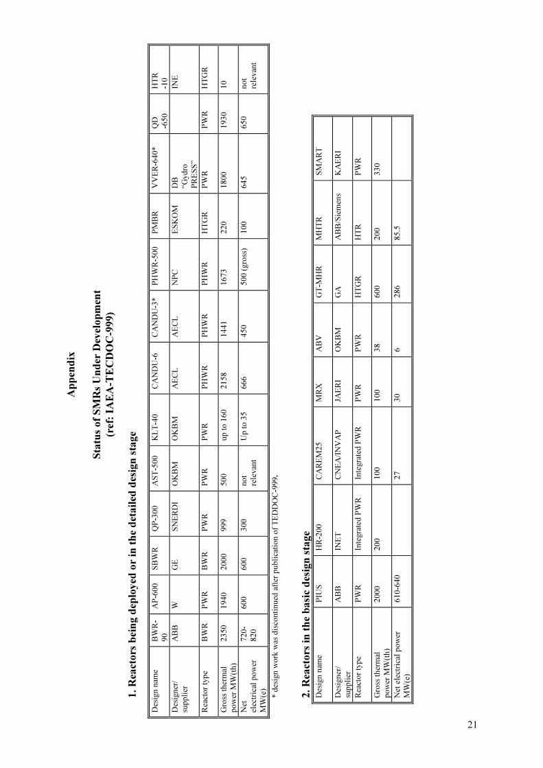
Ap
pen
dix
Sta
tus
of
SM
Rs
Un
der
Dev
elop
men
t
(ref
: IA
EA
-TE
CD
OC
-999)
1. R
eact
ors
bei
ng d
eplo
yed
or
in t
he
det
ail
ed d
esig
n s
tage
Des
ign
nam
e B
WR
-
90
AP
-60
0
SB
WR
Q
P-3
00
A
ST
-50
0
KL
T-4
0
CA
ND
U-6
C
AN
DU
-3*
PH
WR
-50
0
PM
BR
V
VE
R-6
40
*
QD
-65
0
HT
R
-10
Des
ign
er/
sup
pli
er
AB
B
W
GE
S
NE
RD
I O
KB
M
OK
BM
A
EC
L
AE
CL
N
PC
E
SK
OM
D
B
“Gyd
ro
PR
ES
S”
IN
E
Rea
cto
r ty
pe
BW
R
PW
R
BW
R
PW
R
PW
R
PW
R
PH
WR
P
HW
R
PH
WR
H
TG
R
PW
R
PW
R
HT
GR
Gro
ss t
her
mal
po
wer
MW
(th
)
23
50
1
94
0
20
00
9
99
5
00
u
p t
o 1
60
2
15
8
14
41
1
67
3
22
0
18
00
1
93
0
10
Net
elec
tric
al p
ow
er
MW
(e)
72
0-
82
0
60
0
60
0
30
0
no
t
rele
van
t
Up
to
35
6
66
4
50
5
00
(gro
ss)
10
0
64
5
65
0
no
t
rele
van
t
* d
esig
n w
ork
was
dis
con
tin
ued
aft
er p
ub
lica
tio
n o
f T
ED
DO
C-9
99.
2. R
eact
ors
in
th
e b
asi
c d
esig
n s
tage
Des
ign
nam
e P
IUS
H
R-2
00
C
AR
EM
25
M
RX
A
BV
G
T-M
HR
M
HT
R
SM
AR
T
Des
ign
er/
sup
pli
er
AB
B
INE
T
CN
EA
/IN
VA
P
JAE
RI
OK
BM
G
A
AB
B/S
iem
ens
KA
ER
I
Rea
cto
r ty
pe
PW
R
Inte
gra
ted
PW
R
Inte
gra
ted
PW
R
PW
R
PW
R
HT
GR
H
TR
P
WR
Gro
ss t
her
mal
po
wer
MW
(th
)
20
00
2
00
1
00
1
00
3
8
60
0
20
0
33
0
Net
ele
ctri
cal
po
wer
MW
(e)
61
0-6
40
27
3
0
6
28
6
85
.5
21

3. R
eact
ors
in
th
e co
nce
ptu
al
des
ign
sta
ge
Des
ign
nam
e B
WR
-60
0*
VP
BE
R
HS
BW
R
AP
WR
S
IR
ISIS
A
TS
-15
0
MA
RS
R
UT
A-2
0
SA
KH
A-9
2
MD
PR
4
S
Des
ign
er/
sup
pli
er
Sie
men
s O
KB
M
HIT
AC
HI
JAR
EI
Co
nso
rtiu
m
AN
SA
LD
O
OK
BM
U
niv
. o
f
Ro
me
EN
EA
RD
IPE
O
KB
M
CR
IEP
I C
RIE
PI
Rea
cto
r ty
pe
BW
R
PW
R
BW
R
PW
R
Inte
gra
ted
PW
R
PW
R
PW
R
PW
R
po
ol
typ
e P
WR
L
MR
L
MR
Gro
ss t
her
mal
po
wer
MW
(th
)
22
00
1
80
0
18
00
1
80
0
10
00
6
50
5
36
6
00
2
0
7
84
0
12
5
Net
elec
tric
al p
ow
er
MW
(e)
75
0
63
0
60
0
60
0
32
0
20
5
Up
to
18
0
Up
to
18
0
no
t
rele
van
t
Up
to
1
32
5
50
*R
eact
or
des
igns
added
to t
he
Tab
le o
f IA
EA
-TE
CD
OC
-999.
Designer/supplier:
A
BB
A
BB
Ato
m A
B,
Sw
eden
A
EC
L
Ato
mic
Ener
gy o
f C
anad
a L
td, C
anad
a
C
EN
A
Co
mis
ión
Nac
ional
de
Ener
gie
Ato
mic
a, A
rgen
tinia
C
RIE
PI
Cen
tral
Res
earc
h I
nst
itute
of
Ele
ctri
c In
dust
ry, Ja
pan
D
B “
GY
DR
OP
RE
SS
” —
Des
ign B
ure
au G
YD
RO
PR
ES
S,
Russ
ian F
eder
atio
n
E
SK
OM
E
SK
OM
, S
ou
th A
fric
a
G
A
Gen
eral
Ato
mic
, U
nit
ed S
tate
s of
Am
eric
a
G
E
Gen
eral
Ele
ctri
c, U
nit
ed S
tate
s of
Am
eric
a
H
TR
H
igh
Tem
per
ature
Rea
ctor
IN
ET
In
stit
ute
of
Nucl
ear
Ener
gy T
echnolo
gy,
Tsi
nghua
Univ
ersi
ty,
Chin
a
IN
VA
P
INV
AP
Co
mpan
y,
Arg
enti
na
JA
ER
I Ja
pan
Ato
mic
Ener
gy I
nst
itute
, Ja
pan
K
AE
RI
Kore
a A
tom
ic E
ner
gy R
esea
rch I
nst
itute
, R
epubli
c of
Kore
a
N
PC
N
atio
nal
Po
wer
Cooper
atio
n,
India
O
KB
M
Sp
ecia
l D
esig
n B
ure
au f
or
Mec
han
ical
Engin
eeri
ng,
Nej
nin
ovgar
ad,
Russ
ian
Fed
erat
ion
R
DIP
E
Res
earc
h a
nd
Dev
elopm
ent
Inst
itute
of
Pow
er E
ngin
eeri
ng,
Russ
ian F
eder
atio
n
S
NE
RD
I S
han
gh
ai N
ucl
ear
Engin
eeri
ng R
esea
rch &
Des
ign I
nst
itu
te,
Ch
ina
W
W
esti
ngh
ou
se,
Unit
ed S
tate
s of
Am
eric
a
22

Annex
The following papers were produced in the course of this study.
Full text of the papers are provided in this Annex.

.

25
STAFFING REQUIREMENTS FOR FUTURE
SMALL & MEDIUM REACTORS
D. McQUADE
Atomic Energy of Canada Ltd,
Ontario, Canada
Abstract
As power generators around the world grapple with the challenges of the environment,
deregulation, competitions and changing prices of fuels, the economics of running a future power
plant are influenced significantly by the component of labour costs. These costs, from plant staff,
corporate support and purchased services will affect the overall plant economics. To achieve
improved efficiency and effectiveness of organization structures and staff, vendors and utilities are
working jointly to apply lessons learned for future designs. This paper will examine the experience
gained to date with Canadian CANDU 6 type reactors both in Canada and abroad. The strategies
which have been very successful will be reviewed, together with the results of collaboration between
Atomic Energy of Canada and the utilities. An assessment of the staffing numbers is provided as a
comparison between current number at a Canadian utility and the projected number from a future
plant with the improvements in the design. The influence to the overall plant economics are discussed
with some broad generalities that look at the effects of increasing and reducing staff levels showing
the probable impact on capacity factor. The lessons from other plants can contribute significantly to
the performance improvement process. The paper points to the need for a balanced approach in the
future for the distribution of operating maintenance and administration (OM & A) cost between
nuclear safety studies; maintenance programs and staff training. In the future, utilities, together with
the designers will have to greatly improve plant maintenance and training. The improved design
features detailed in the paper will support this strategy by utilizing operational experience.
1. INTRODUCTION
The paper reflects the experience gained over 29 years on various CANDU reactors in
Canada. Emphasis is placed on the experience of Ontario Hydro and New Brunswick Utilities
from the following nuclear power plants (NPP); Nuclear Power Development Plant, Rolphton,
25 MW(e); demonstration Plant Douglas Point, 200 MW; first commercial plant, Pickering
‘A’, 4 � 540 MW and Point Lepreau 668 MW. Ontario Hydro and New Brunswick Power
models are suitable for consideration for small and medium reactors as they reflect a
significant history of operation between 1964 and 1998.
These utilities modelled their stations to operate independent of outside resources and
services, by training developing staff to perform the majority of plant activities. In order to
meet the planned nuclear expansion program, additional staff were included in the initial
station staff complement. Each station had a dedicated planning and technical support group
on site.
The major off site services were for design, analysis and highly specialized work e.g.
nuclear reactor/piping in-service inspections, boiler metallurgical inspections, and specific
turbine generation specialty work.
There was a co-operative effort between the utilities of Ontario Hydro and New
Brunswick Power; where Ontario Hydro agreed to support New Brunswick Power by
providing staff, training and documentation. New Brunswick Power planned to follow the
successful Ontario Hydro model for a second planned unit (to date not yet committed).

26
2.1. Experience of small and medium reactors (SMR) operation
2.1.1. Current organization, qualification & staff by function
For this discussion a single CANDU 6 700 MW unit will be described. The basic
organization is as shown.
(a) Operate plant (a) Technical
support
(a) Planning (a) Training new
staff
(a) Materials
management
(b) Maintain
equipment
(b) Design
interface
(b) Scheduling (b) Co-ordinate
training
(b) Accounts
Function:
�� Fueling
�� Documentation
production
�� Monitoring
work
�� Manage
simulator
�� Budget
�� Chemistry
�� Nuclear safety �� Co-ordination
work
�� Clerical
�� Waste
management
�� Surveillance
monitoring
�� Payroll
�� Personnel
The organization has 5 main groups: production, technical, planning, training and
business with two support groups, QA and health physics. Table � gives a general account of
the staff numbers and their respective function.
The main function and qualification of each group is as follows:
Production function
Operators to operate all systems; Trades staff for all maintenance; Fueling staff to fuel
reactor and manage spent fuel; Chemistry group to run lab and monitor/maintain chemistry.
Qualifications
Operators — high school grade 12 minimum. Preferences to those with community college
science courses beyond high school. Hired as trainee and developed to the various operator
levels through the company training program.
Station Manager
Health Physics QA
Production Technical Unit Planning Training Business

27
TABLE I CANDU 6 SINGLE UNIT STAFFING AND FUNCTION
Staff designation Staff
level
Function
Management (includes VP
nuclear)
6
Various corporate support
Station manager 1 Oversee entire plant operation.
Planning 8 Plan, schedule, monitor & coordinate all work.
Store (supply) 20 Material management, spare part storage.
Production manager 1 Manage operation, maintenance, fueling & chemistry.
Operations 89 Operate all plant equipment
Maintenance 151 Maintain all plant equipment
Fueling 28 Operate & maintain fuel handling systems
Chemistry 18 Sample, monitor, initiate action to maintain chemistry specs.
Technical manager 1 Manage technical unit to support production & ensure reactor
safety.
Technical EC&I 33 Technical engineering specialist for electrical &
instrumentation & control
Technical mechanical 31 Technical engineering specialist for mechanical & process
systems
Technical specialists —
Safety systems
14 Technical engineering specialist for 4 special safety systems
Technical engineering
services
5 Technical engineering specialist for project management &
contractor services
Nuclear safety manager 1 Maintain nuclear safety analysis & licensing
Nuclear safety analysis 11 Carry out safety evaluations & special analysis
Regulatory affairs (licensing) 3 Deal with all licensing & related issues
Nuclear safety reliability 4 Practical reliability model, monitor & evaluate plant
performance.
Administration manager 1 Manages administration, material procurement, accounts,
security etc.
Public affairs 1 Interface with plant and public, media, local community
Budget and cost control 1 Monitor budget and cost
Security 22 Provide plant security
Administrative support
(clerical)
38 Services for typing, document management,
procurement role.
Training 20 Coordinate & provide training for all staff.
Quality assurance 8 Support the station manager with QA activities.
Health physics 21 Define policy and develop procedures for radiation plant.
Health physics (laboratory) 3 Perform all lab work for dose monitoring programs.
Total staff 534
Technical function
Provide technical support for the production group. Prepare operating, maintenance and
training manuals. Interface with design support groups. Develop staff to become system
specialists to carry out system surveillance, plant monitoring and evaluation. Ensure
documents and systems provide the required level of nuclear safety. Prepare detailed work

28
plans for plant outages and breakdowns. Prepare station performance reports. Provide
computer, electronic, electrical and reactor physics specialists.
Qualifications
An engineering degree is required. Previous industrial experience may be an asset. All
technical staff complete the station training program. Shift supervisors are drawn from this
pool of technical staff.
Planning function
Manage the work program; to ensure maintenance is done during operation; prepare
outage schedules and forced outage plans.
Qualifications
The senior who directs the group is an ex shift supervisor. The planners are selected
from control room operators or capable trades staff.
Training function
The training group runs the training center and simulator, coordinates the preparation
and delivery of all the required training.
Qualifications
Manager is an ex-shift supervisor. Other trainers are from technical control room
operators and capable trades staff.
Business function
Provide all services to support the various station functions: for material management,
clerical support, budget and accounting, personnel, payroll and security.
Qualifications
Manager is selected from utility organization. Business staff are from high
school/college.
Quality assurance function
Carry out all quality assurance functions and audits for the plant manager.
Qualifications
Staff are ex shift supervisors. Other capable staff from various departments.
Health physics
Support to the station for radiation protection. Coordinate and prepare all procedures for
plant emergencies and provide an interface for the various civil authorities. Provide training to
all staff in scientific matters related to radiation and health.
Qualifications
Senior specialists with university degree. Support staff drawn from the ranks of station
staff and given special training in health physics group.

29
2.1.2. Experiences and strategies to optimize staff
The strategy used for the CANDU reactors in Canada for staff optimization is one that
focused on staff selection, training and development; using written procedures for most tasks.
The aim was to develop staff to have a very broad understanding of the various attributes of
Nuclear Power. The operations staff were responsible for commissioning all units. Interaction
between the station staff and the major suppliers and manufacturers was actively encouraged
to improve the understanding and relationship between the manufacturers and the users.
Feedback processes were set up between the utility and the major supplies to ensure that
operator and maintenance feedback was provided to improve future products. This proved to
be very effective and was a major contribution to the early life high capacity factors.
The operational strategy for the stations was to develop a very strong on-site technical
and planning capability, to support operation and maintenance activities on a shift basis, 24 hr
a day 7 days per week. This was to enable the stations to cope with most types of expected
upsets and breakdowns. The technical group were able to secure additional specialized
services as the need arose.
The concepts of composite trade was agreed to between management and the unions.
The objective of the composite trade was to provide training to employees to expand the type
of tasks they would be capable of performing. For example, in the Electrical I&C shop the
staff are called control technicians and they each have a high skill level in electrical —
instrumentation — controls — electronics. Each person had a main strength in one discipline
and the appropriate additional skills are select and developed for the individual.
The broad base training requirement was part of the initial staffing strategy and
considerable effort was made at the onset to select candidates with the greatest potential for
composite trades. This fundamental strategy is quite basic, but has proven very effective.
Experience has shown that by selecting competent people; providing well organized
training; and providing staff with well prepared procedures, work is done well, safety is not
compromised and capacity factors are high.
2.1.3. Relations between staff cost and plant performance
For the Canadian Utilities the various ‘costs’ for an NPP are shown on Table ��.
Operation maintenance and administration (OM & A) is the cost most influenced by staff
numbers.
The detailed cost elements of OM & A are shown on Table ���. Also shown, for
clarification, are cost elements that are not included in OM & A costs.
The percentage contribution to the total OM & A is shown on Table �V.
Station staff costs are about 54% of total OM & A, while hired, contract and consulting
services account for about 20%. Thus the total portion of OM & A costs related to manpower
is about 74%. It is this portion of OM & A costs where organizations look to make ‘Savings’.
The cost performance model on Figure 1 should be studied carefully when trying to
optimize staff levels. The figure shows that the operating costs should be to the right of the
lowest point. If OM&A costs are driven down to the extent that they are to the left of the
lowest point, the impact on the overall cost of generation is dramatic. The overall cost will be
extremely high and the possibility of nuclear shut down is also high. Recent experience in
Canada attests to the validity of this conceptual model.
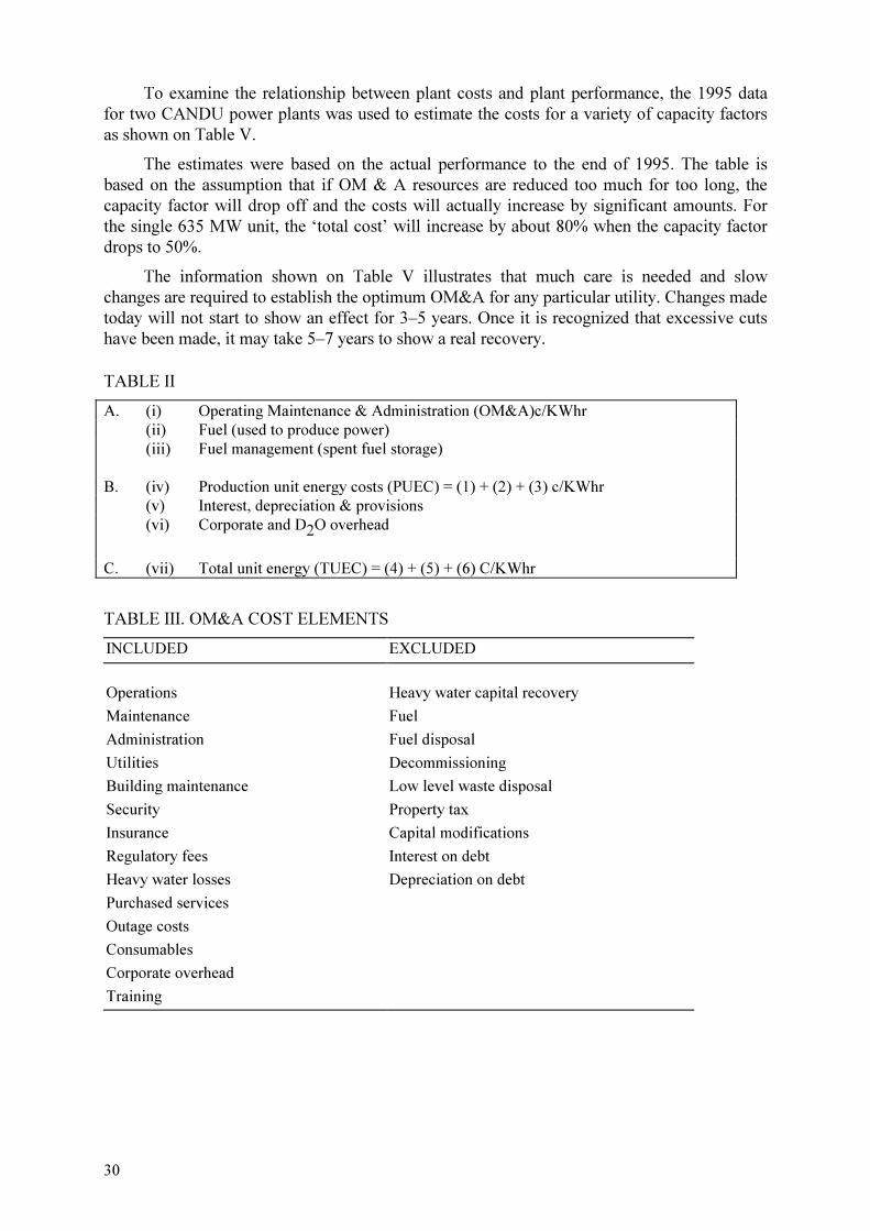
30
To examine the relationship between plant costs and plant performance, the 1995 data
for two CANDU power plants was used to estimate the costs for a variety of capacity factors
as shown on Table V.
The estimates were based on the actual performance to the end of 1995. The table is
based on the assumption that if OM & A resources are reduced too much for too long, the
capacity factor will drop off and the costs will actually increase by significant amounts. For
the single 635 MW unit, the ‘total cost’ will increase by about 80% when the capacity factor
drops to 50%.
The information shown on Table V illustrates that much care is needed and slow
changes are required to establish the optimum OM&A for any particular utility. Changes made
today will not start to show an effect for 3–5 years. Once it is recognized that excessive cuts
have been made, it may take 5–7 years to show a real recovery.
TABLE II
A. (i) Operating Maintenance & Administration (OM&A)c/KWhr
(ii) Fuel (used to produce power)
(iii) Fuel management (spent fuel storage)
B. (iv) Production unit energy costs (PUEC) = (1) + (2) + (3) c/KWhr
(v) Interest, depreciation & provisions
(vi) Corporate and D2O overhead
C. (vii) Total unit energy (TUEC) = (4) + (5) + (6) C/KWhr
TABLE III. OM&A COST ELEMENTS
INCLUDED EXCLUDED
Operations Heavy water capital recovery
Maintenance Fuel
Administration Fuel disposal
Utilities Decommissioning
Building maintenance Low level waste disposal
Security Property tax
Insurance Capital modifications
Regulatory fees Interest on debt
Heavy water losses Depreciation on debt
Purchased services
Outage costs
Consumables
Corporate overhead
Training

31
TABLE IV. PT. LEPREAU OM&A COSTS 1994/95 Category Description Percent
Operating staff regular staff wages and salaries 53.6%
Hired services extra staff for outages or heavy work load 3.7%
Contracted services principally COG membership, includes specialty
contract work (e.g. SG cleaning)
8.7%
Consulting services supplement to station technical staff 7.5%
Materials consumables including D2O 12.4%
Regulatory fees licensing fees 4.0%
Tools and equipment specialty tools and equipment 0.7%
Vehicles cars, trucks, special vehicles 0.3%
Travel expenses for staff travel and attached staff 0.7%
Communications major element is telephone costs 0.7%
Properties maintenance of grounds and buildings 0.8%
Insurance larger utilities may 'self-insure' 5.5%
Other training costs (other than salaries), public
relations, etc.
1.3%
Total 100.0%
Nuclear Operating Costs ($)
OverallSystemCost of
Generation($)
Optimum nuclear operating costs,
lowest overall system costs
Area of possible nuclear shutdown
FIG. 1. OM&A cost optimization.1
1 E. Horton and T.R. Sepa (OHN), presented at OECD/NEA International Symposium on Achievement of Good
Performance in Nuclear Plants, Tokyo, Japan, April, 1989.

32
TABLE V. CAPACITY FACTOR IMPACT ON UNIT ENERGY COSTS, SHOWN AS %
50%
Capacity
Factor
80%
Capacity
Factor
85%
Capacity
Factor
90%
Capacity
Factor
94%
Capacity
Factor
100%
Capacity
Factor
4 × 881 mw
OM&A cost
(c/KWhr Net)
60.7 12.3 5.5 1 – 19.7
PUEC cost (c/KWhr Net) 42.3 12.1 6.1 1 – 16.9
Total cost (c/KWhr Net) 67.9 12.5 5.8 1 – 12.3
1 × 635 mw
OM&A cost
(c/KWhr Net)
88.0 25.4 17.6 11.5 *1 – 6.0
PUEC cost (c/KWhr Net) 74.6 24.0 17.3 10.5 *1 – 6.0
Total cost (c/KWhr Net) 80.0 21.4 14.3 7.7 *1 – 6.0
*Actual performance to year end 1995 is base of 1
2.1.4. Recommendations to designer
The following is a general list of basic recommendations and suggestions:
(i) Provide mature well proven design — little need for modification;
(ii) Fully analyzed for all conceivable eventualities and clearly identify all assumptions
made relating to operators and maintenance — little ongoing analysis;
(iii) Completed P.S.A. prior to construction completion — little need for revising operating
documents to reflect the design back fits;
(iv) Ensure complete and coherent set of design documents — minimize configuration
management efforts; reduce OM&A;
(v) Ensure a fully detailed list of all environmentally qualified equipment and components
— ease maintenance burden; will avoid inappropriate parts replacement; reduce
OM&A;
(vi) Procurement of well proven, high quality equipment — provide high reliability and
reduce OM&A;
(vii) Operator displays that really assist with plant upsets and automation of routine
activities — more reliable and safe plant performance; reduce OM&A;
(viii) Comprehensive maintenance manual based on reliability centered maintenance
techniques for effective and efficient maintenance — improve plant maintenance from
the start; reduce OM&A;
(ix) Provide features to accommodate extensive condition based maintenance — improve
maintenance effectiveness and efficiency; reduce OM&A;
(x) Provide more maintenance support facilities i.e. provision to clean boilers, service
outlets where inspections are done — lower maintenance costs; reduce OM&A;
(xi) Integration of modern information technology into plant design — avoid costly
additions, assist utility to improve productivity and reduce OM&A;
(xii) Enter into a service agreement with the client that is based on a win-win agreement —
lowers customer’s cost and improves plant performance.

33
Experience has shown that in the past, these above features were not always provided.
After 30 years of design and operation, new plant installation should not require the extensive
modification experienced by many utilities in their early years of nuclear operation.
Older plants have operated with a very high cost for ongoing safety analysis. Today the
industry is highly developed and the need for expensive ongoing work should be very limited.
Only where probable events have been overlooked should changes be made to plant operation
or design.
Probabilistic safety analyses are being done in ever increasing detail and this all has to
be financed, usually from OM & A funds. Also the current work being done around the world
on the reconstitution of the design basis, brings with it the heavy cost burden for utilities. The
delivered design documents must be improved for the client.
The issue of ‘environmental qualified equipment’ and maintaining the qualification
throughout the 40 year life of the plant is a demanding job for the operations and maintenance
organization. The task can be made significantly easier when all equipment and components
are clearly identified, together with the condition for which they have been qualified.
Much work has been done in examination of the man machine interface for control room
operators. This should result in a layout which simplifies routine operations, and allow
operators to focus on initiating event(s) that cause plant upsets.
Include as part of the plant design, modern information and communication facilities.
Finally, offer new client a viable service agreement on a win-win basis. This would be
arranged to assist the client achieve maximum performance of the unit.
2.1.5. External factors influence staffing
There are three main external factors which influence the staffing: company policy —
tending to reduce numbers; regulator influence — tending to increase numbers; and trends
within the nuclear industry — tending to increase numbers.
Company policy
Utilities try to hold down costs. Staffing is seen as a major cost element over which
there is some control. For a mature NPP there is continual pressure to limit staffing costs and
minimize the OM & A costs.
When a utility enters the nuclear business, there is an expectation that further plants will
follow. The strategy used by Ontario Hydro in the early days, was to have extra staff, who,
while contributing to the NPP work programs, were also being trained for a future assignment
at the next station. This strategy was very effective and contributed significantly to the early
success in Ontario Hydro. The ‘extra’ 25% development staff were termed ‘management
development staff’ (MDS) where the wages for the group was a capital expense and accrued
against the next station. Point Lepreau followed this model to a lesser extent, as the future of
their next station was uncertain.
The major benefit from this O.H. strategy was that the commissioning and operations
group in a new station, were never short of well trained, highly skilled staff. The investment
gave a very good return.
When the plants matured, the staffing level was reduced due to severe pressure to cut
costs. Much of the current difficulties in O.H. and NBP are linked to the cost reduction
initiatives. As mentioned previously, great care is required in optimizing staff numbers.

34
Regulator influences
The influence of the regulators over the years, has been very significant and pressure
from the regulators have resulted in higher staff requirements. Initially this influence affected
functions which were related to QA, and safety analysis, which increased support staff.
Eventually the influence extended into the other areas of plant operation and maintenance.
Staff numbers were adjusted to cope with additional demands of bureaucracy, reporting,
record keeping, verification approvals etc.
As a result of the safety analysis work, plant modifications resulted in major work
programs. This required more staff in all areas including engineering, technical support,
training, administration, operation and maintenance.
The regulators introduced new requirements for new plants, which, in many cases, were
backfitted placing more demands on operation and maintenance staff. More staff were hired.
Trends within the nuclear industry
The Nuclear Industry has placed high demands on itself. Several major incidents of note
highlighted areas where improvements should be made. Extensive interchanges within the
industry developed and various institutions were created to improve the performance record of
the industry.
Major initiatives were taken in the following fields:
�� Training
�� Man-machine interface
�� Environmental qualification
�� Accident analysis — extreme events
�� Improved maintenance and supervision
�� Emergency preparedness
�� Operating experience
�� Configuration management
�� Design bases reconstitution
�� Conduct of operation and maintenance staff
Each of these has added to the need for staff and is essentially an ongoing program.
After four decades the situation should stabilize and long term staff requirements should
be easier to determine.
2.1.6. Lessons learned
The major lessons learned from the nuclear power program in Canada regarding staffing
requirements are as follows:
(i) The total magnitude of the job should not be under estimated.
(ii) Recognize the main areas requiring staff and staff each from the beginning with the
appropriate numbers.
(iii) Avoid the tendency of staffing to satisfy the demands regulator, at the expense of the
operating and maintenance staff. Ensure there is always a balance.
(iv) Do not economize at the expense of training. Training is an investment to provide a
well operated and maintained plant. Have sufficient staff to allow a consistent portion
to be on a training program.
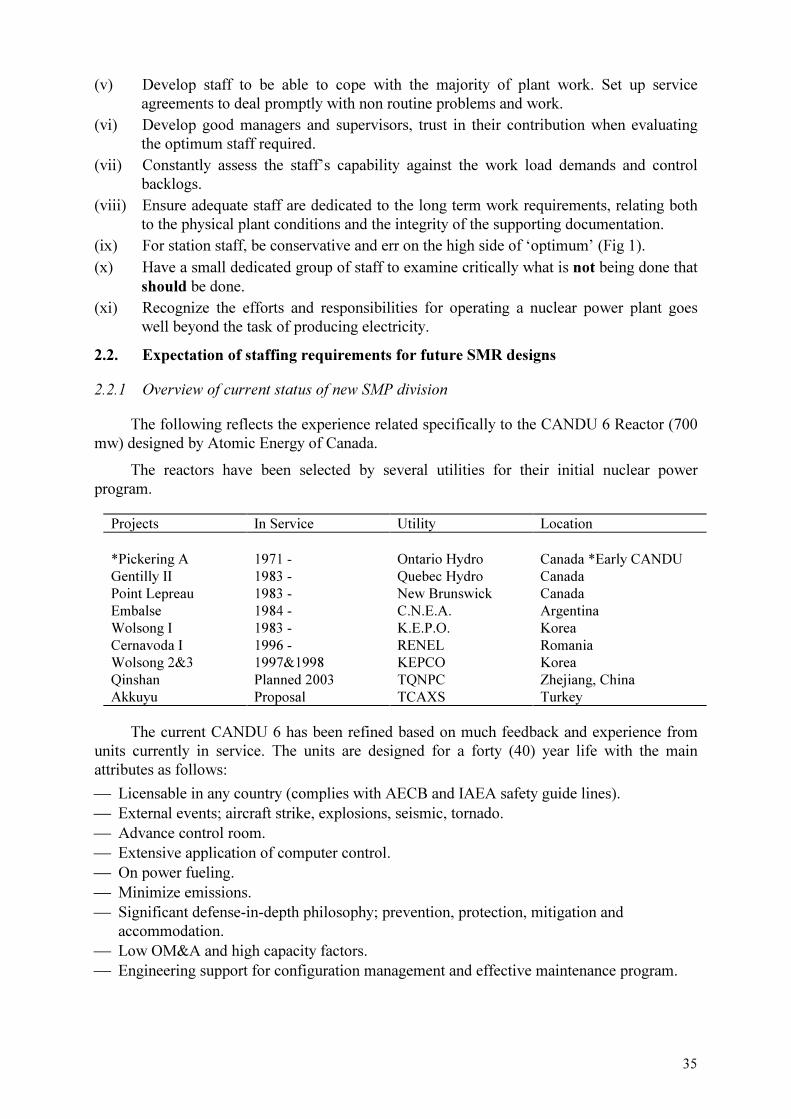
35
(v) Develop staff to be able to cope with the majority of plant work. Set up service
agreements to deal promptly with non routine problems and work.
(vi) Develop good managers and supervisors, trust in their contribution when evaluating
the optimum staff required.
(vii) Constantly assess the staff’s capability against the work load demands and control
backlogs.
(viii) Ensure adequate staff are dedicated to the long term work requirements, relating both
to the physical plant conditions and the integrity of the supporting documentation.
(ix) For station staff, be conservative and err on the high side of ‘optimum’ (Fig 1).
(x) Have a small dedicated group of staff to examine critically what is not being done that
should be done.
(xi) Recognize the efforts and responsibilities for operating a nuclear power plant goes
well beyond the task of producing electricity.
2.2. Expectation of staffing requirements for future SMR designs
2.2.1 Overview of current status of new SMP division
The following reflects the experience related specifically to the CANDU 6 Reactor (700
mw) designed by Atomic Energy of Canada.
The reactors have been selected by several utilities for their initial nuclear power
program.
Projects In Service Utility Location
*Pickering A
1971 -
Ontario Hydro
Canada *Early CANDU
Gentilly II 1983 - Quebec Hydro Canada
Point Lepreau 1983 - New Brunswick Canada
Embalse 1984 - C.N.E.A. Argentina
Wolsong I 1983 - K.E.P.O. Korea
Cernavoda I 1996 - RENEL Romania
Wolsong 2&3 1997&1998 KEPCO Korea
Qinshan Planned 2003 TQNPC Zhejiang, China
Akkuyu Proposal TCAXS Turkey
The current CANDU 6 has been refined based on much feedback and experience from
units currently in service. The units are designed for a forty (40) year life with the main
attributes as follows:
�� Licensable in any country (complies with AECB and IAEA safety guide lines).
�� External events; aircraft strike, explosions, seismic, tornado.
�� Advance control room.
�� Extensive application of computer control.
�� On power fueling.
�� Minimize emissions.
�� Significant defense-in-depth philosophy; prevention, protection, mitigation and
accommodation.
�� Low OM&A and high capacity factors.
�� Engineering support for configuration management and effective maintenance program.

36
2.2.2. Review of design & expected operating characteristics of future SMR
The following list shows the essential characteristics of future SMR design which
should lead to better use of staff:
(i) Proven product with built-in improvements from design, commission, and operational
feedback.
(ii) The feedback experience should be systematically applied based on:
�� What did not work well and why.
�� What improvements have been made to resolve the problems in (i).
�� What has worked well and should remain.
�� What was not included and should be provided in the future.
(iii) Systems and equipment that provide ease of maintenance and operation.
(iv) Provide control room staff with a user friendly interface to the systems, providing ease
of monitoring and annunciation interpretation.
(v) Provide abundant monitoring provisions for systems and equipment to maximize the
application of condition based maintenance techniques. Establish a comprehensive
maintenance program.
(vi) Provide the client with completely integrated design documents and electronic
facilities to allow the client to maintain effective configuration management from the
beginning of the operation.
(vii) Provide the maximum amount of automation, particularly for routine testing and for
normal operation.
(viii) The design should be mature to the extent that little if any future analysis or
modification work would be required.
(ix) Provide complete and comprehensive service facilities as a built in feature where
systems and equipment will require extensive inspection and maintenance activities.
(x) Include modern information management facilities for all aspects of the operation,
maintenance and administration as part of the design.
By providing an improved design, staff may focus on the production of power, and
maintenance of equipment and systems.
2.2.3. Estimate of the number of staff to operate a new SMR
Before providing an estimate of staff numbers required to operate a new SMR, it is
important to appreciate the staffing model used and the major assumptions. The numbers
shown on Table IV reflect a single unit, built in Canada, on a coastal location, some distance
from the main industrial centres. The utility strategy is to be reasonably independent and have
sufficient staff to cope with the majority of normal maintenance work. Specialist services will
be purchased for specific work requiring specialized skills.
The major assumptions used to establish the staff numbers for a new CANDU 6 are:
�� Staff will be hired and trained to develop independence.
�� Contract agreements with labour unions will include multi-skilled staff and composite
trades for flexibility of assignments.
�� The design features listed in 2.2.2 above are provided.

37
�� Limited regulatory pressure/influence because of high confidence in the design and
operating organization.
�� Effective material management systems for supply of spare parts.
�� Extensive application of lessons learned from other utilities.
�� Utilize best practices, work management and outage planning techniques.
�� Implementation of modern information management facilities.
�� Highly rated training program.
Based on the above, the staff shown on Table VI are expected to be fully trained and
competent in all aspects of each job. It is reasonable to expect that this would be achieved in
the first 5 years of full power operation. During that period additional staff of 10%–25%
would be required. The staff shown are the total staff for all station operation maintenance and
administration.
The basic qualifications for the staff would be as shown previously in Section 2.1.1.
All staff would require specific training within the utility for common subjects covering
science fundamentals, radiation protection, worker safety, nuclear system & processes, basic
and advance nuclear physics. Specialized training is also provided for the various work groups
of operation, mechanical, electrical, instrument and control, services, chemistry, technical
support etc.
It is also assumed that the single unit has a simulator and training centre, (staff number
included in Table VI).
2.2.4. Joint studies between design and operator staff
AECL and utility operators have carried out a number of joint studies; the main topics
addressed have been:
�� Operating, maintenance and administration cost reduction (OM & A).
�� Capacity factor improvement.
�� Plant life management.
�� Maintenance program based on RCM principles.
�� Application of 3-D CADDS to reduce OM&A costs.
�� Commissioning program schedule reduction.
�� Main control center development program.
Each of these studies has had active participation by CANDU 6 utilities. The result of
these efforts is an improved CANDU 6 product, which will minimize OM&A cost, maximize
capacity factor, provide effective maintenance programs and have an advanced control room
providing safer and more effective operation.
2.2.5. Recommendation on qualification & training requirements
Future nuclear utilities should avoid using the staffing model for conventional power
plants to staff a nuclear power plant. Due to the increased diversity and regulatory demands, it
is recommended to adopt a staffing model that has worked well for other nuclear utilities.
The IAEA has extensive publications on the topic of training and staff development. The
first recommendation for a potential new client is to have an association with the IAEA and or
INPO etc., and select from their benchmarking material.
The various job families in the organization must be clearly identified and a dedicated
training and development program put in place for each job family. When entering a nuclear

38
TABLE VI. UPDATED OM&A STAFFING FOR A NEW CANDU 6 STATION
Pt. Lepreau CANDU 6 CANDU 6 CANDU 6
Staff Designation 1-Unit (1997) 1st Unit 2
nd Unit 2-Units
Management (head office) 6 6 1 7
Station manager 1 1 0 1
Planning 6 6 3 9
Stores 18 16 6 22
Production manager 1 1 0 1
Operations 79 81 75 152
Maintenance 141 141 109 250
Maintenance support 0 7 4 11
Fuelling 21 21 19 40
Chemistry 16 16 10 26
Technical manager 1 1 0 1
Technical EC&I 23 21 16 37
Technical mechanical 25 22 18 40
Technical specialists — safety systems 12 12 9 21
Technical engineering services 3 3 2 5
Nuclear safety manager 1 1 0 1
Nuclear safety analysis 11 4 0 15
Nuclear safety licensing 3 2 0 4
Nuclear safety reliability 4 3 1 6
Administration manager 1 1 0 1
Public affairs 1 1 0 1
Budget and cost control 1 1 0 1
Security 21 21 0 21
Administrative support (clerical) 34 32 11 43
Training 18 18 9 27
Quality assurance 8 8 2 10
Health physics 19 17 10 27
Health physics laboratory 3 3 1 4
TOTAL 478 467 306 773
power program, partnering with another utility has proven to be successful. With this
partnership, key staff assignments can be made with the utility for on-the-job training.
Entering into a contract for a new nuclear plant, the client should specify that the SMR
supplier provide a training program to develop the utility staff to a level of competence to
safely run the plant at full power. This is one of the most cost effective ways of gaining
competence. CANDU 6 projects have been done this way, in each case it has been very
effective. There may be a tendency for the client to minimize staff committed to training
programs in an off-shore assignment. This should be given careful consideration as training is
an investment and it is one of the costs of doing business. It takes a significant amount of time
and effort to hire and fully develop staff; good training is indispensable.
Senior management and supervisory staff training should be an integral part of all
training programs. Good managers and supervisors are the key to well run plants.
2.2.6. Features in new design
To improve the design of the CANDU 6 product, AECL has worked closely with
various CANDU 6 utilities. AECL has also participated in several international committees
and conferences. The Product Development Program provides the following features:

39
Improvements
Benefits
1. Improve material selection for feeders Lower maintenance
2. Improve design of pressure tube Longer life, less maintenance
3. Improve chemistry control features Less plant degradation
4. Improve ventilation systems Minimize D20 loss and emissions
5. Improve boiler design Increase plant performance and
maintenance
6. Improve control room layout & plant display
systems
Improve plant performance
7. Increase automation features for operation testing &
annunciation integration
Lower OM&A costs
8. Provide extensive plant monitoring features to
maximize condition based maintenance features
Lower OM&A costs.
9. Provide integrated electronic design documentation
for ease of configuration management
Lower OM&A costs.
10. Provide full 3-D CADDS facilities for viewing all
drawings
Lower OM&A costs.
11. Improve computerize material management system Lower OM&A costs.
12. Provide comprehensive electronic databases for
design details on plant equipment
Lower OM&A costs
13. Provide comprehensive maintenance program
focused on CBM and RCM
Lower OM&A costs.
Each of these features result from feedback from various clients. Many other smaller
improvements have been made also. The objective is to provide the client with a
competitively priced NPP with reasonably low OM&A costs.
2.2.7. Comparison of staff requirements between currently operating and new designs
Recent studies carried out by AECL have been done to establish recommended staffing
levels for new plant design. The model used is that described in Section 2.2.3 above. The staff
distribution proposed makes the assumption that the previous decades of concern and effort
will be integrated into the new design as part of the design improvements and be a one time
expense on the initial capital costs.
Recent experience at Point Lepreau is given as an example for comparing staff
requirements. A backlog of maintenance and configuration management issues among other
things resulted in a reduction of plant performance. To overcome these difficulties, the staff at
the station was increased from 478 in 1996 to about 600 in 1998. The current AECL estimate
for a new CANDU 6 based on the Point Lepreau model (as outlined above) with all the design
improvements is 467 fully trained and experienced staff (see Table VI). No adjustments have
been made for the influences of a foreign location.
It is understood that a new client would have to operate for several years with an
additional staff of 10%–25% while adopting the best practices identified as benchmarks by the
various nuclear institutions. It also assumes that the NPP organization has composite trades

40
and embraces the modern facilities of information technology to support the running of their
business.
2.2.8. External factors which influence staffing regulators
For future stations, there is an expectation that the regulators should not cause the
staffing numbers to increase. The design, analysis, construction and commission will assure a
proven product. The area of focus will now shift to the performance of management,
supervisors, operators and maintainers who are responsible to safeguard the workers and
public. Providing the utility applies the lesson of the past, little escalating pressure should
result from the regulator.
However, if the regulator shifts the focus from design to operations staff performance,
and levels the same influence as in the past with relation to the design issues, then there will
be significant pressure and that will likely result in staff increases.
Despite 40 years of operation, nuclear power is still not widely accepted by society. In
an effort to satisfy the public, some very conservative practices have been adopted by the
nuclear industry. Continuing this trend may continue to increase staff levels. Additional
pressure to increase staff levels will result from: continued social pressure to make plants
safer; environmentalists gaining support that nuclear power is a threat; and bureaucrats
insisting on more checks and balances. A point of interest in Canada is that while the
designers work out ways to automate the plants and reduce the numbers of shift workers, the
utilities adopt practices for emergency preparedness that tends to increase the number of shift
workers.
Vendor support
Support from the vendors offer a real opportunity to enter into a win-win service
agreement, where with careful selection of services, staffing numbers could be reduced. This
area has not been explored to the full extent.
Company policy
The final note relates to company policy, which is the key to staffing. The Nuclear
Industry is such that mistakes made by one utility that result in a nuclear incident, reflects
poorly on the whole industry.
An enlightened company policy will recognize the fact that, as shown on Fig. 1, OM &
A costs that are too low for too long result ultimately in very high total costs. There is a need
for a balanced approach on the disbursement of OM & A funds to secure the optimum nuclear
defense in depth from the three major elements: (1) highly reliable special safety systems; (2)
high quality components and process systems; (3) well trained and equipped staff.
In the past, limited OM & A funds were directed to safety analysis at the expense of
maintenance and training. Future plants with built-in safety features should not experience this
problem. Managers will be able to focus on improving plant maintenance and staff training.
These improvements will result in a safer nuclear power plant.
Conclusion
Future plants that are well designed and improved through user feedback will provide a
good return when the focus of the utility is to have an excellent maintenance program,
supervised and executed by adequate numbers of fully trained staff. Management and
supervisors, following the desired code of conduct, will result in a well run economical NPP.
This should be the aim for the future.
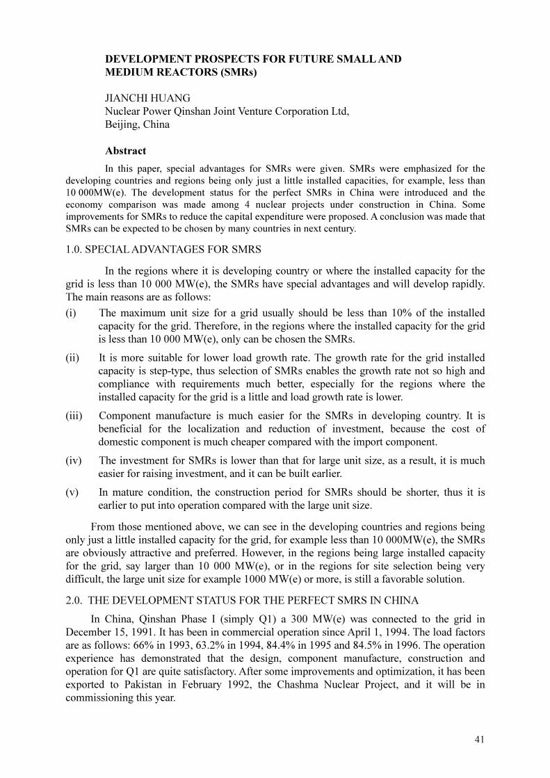
41
DEVELOPMENT PROSPECTS FOR FUTURE SMALL AND
MEDIUM REACTORS (SMRs)
JIANCHI HUANG
Nuclear Power Qinshan Joint Venture Corporation Ltd,
Beijing, China
Abstract
In this paper, special advantages for SMRs were given. SMRs were emphasized for the
developing countries and regions being only just a little installed capacities, for example, less than
10 000MW(e). The development status for the perfect SMRs in China were introduced and the
economy comparison was made among 4 nuclear projects under construction in China. Some
improvements for SMRs to reduce the capital expenditure were proposed. A conclusion was made that
SMRs can be expected to be chosen by many countries in next century.
1.0. SPECIAL ADVANTAGES FOR SMRS
In the regions where it is developing country or where the installed capacity for the
grid is less than 10 000 MW(e), the SMRs have special advantages and will develop rapidly.
The main reasons are as follows:
(i) The maximum unit size for a grid usually should be less than 10% of the installed
capacity for the grid. Therefore, in the regions where the installed capacity for the grid
is less than 10 000 MW(e), only can be chosen the SMRs.
(ii) It is more suitable for lower load growth rate. The growth rate for the grid installed
capacity is step-type, thus selection of SMRs enables the growth rate not so high and
compliance with requirements much better, especially for the regions where the
installed capacity for the grid is a little and load growth rate is lower.
(iii) Component manufacture is much easier for the SMRs in developing country. It is
beneficial for the localization and reduction of investment, because the cost of
domestic component is much cheaper compared with the import component.
(iv) The investment for SMRs is lower than that for large unit size, as a result, it is much
easier for raising investment, and it can be built earlier.
(v) In mature condition, the construction period for SMRs should be shorter, thus it is
earlier to put into operation compared with the large unit size.
From those mentioned above, we can see in the developing countries and regions being
only just a little installed capacity for the grid, for example less than 10 000MW(e), the SMRs
are obviously attractive and preferred. However, in the regions being large installed capacity
for the grid, say larger than 10 000 MW(e), or in the regions for site selection being very
difficult, the large unit size for example 1000 MW(e) or more, is still a favorable solution.
2.0. THE DEVELOPMENT STATUS FOR THE PERFECT SMRS IN CHINA
In China, Qinshan Phase I (simply Q1) a 300 MW(e) was connected to the grid in
December 15, 1991. It has been in commercial operation since April 1, 1994. The load factors
are as follows: 66% in 1993, 63.2% in 1994, 84.4% in 1995 and 84.5% in 1996. The operation
experience has demonstrated that the design, component manufacture, construction and
operation for Q1 are quite satisfactory. After some improvements and optimization, it has been
exported to Pakistan in February 1992, the Chashma Nuclear Project, and it will be in
commissioning this year.

42
The Qinshan Phase II (simply Q2) 2 × 650MW(e), located near Q1 2km away and
started on June 2, 1996 first concrete pouring, now is smoothly under construction. It will put
into operation in June 2002. The design, some components manufacture and construction are
performed by Chinese side, but Framatome and EDF provide technical assistance in NI, and
Stonewebster provides that in CI, mainly in consultation and design reference documents,
including drawings, internal documents, scientific softwares and CAD softwares [1].
Q2 is based on the technologies of DaYa Bay NPP. The safety level for Q2 is similar to
DaYa Bay NPP. In addition to consideration of DBA, it also considered extra design basic
accidents and applied the procedures, such as ATWT, H1 to H4, and U1 to U5 procedures
against extra DBA. In order to obtain best safety, the power density in core for Q2 is less than
that for DaYa Bay NPP for 10%. The specific volume for pressurizer is larger than DaYa Bay
NPP for 20%. The medium pressure safety injection accumulators are connected to RPV
directly. Each steam generator has one 100% motor driven pump and one 100% steam driven
pump for the auxiliary feed water pump system. Also, containment continue ventilation
system is a 4 × 50% capacity system. All indicated above enable the safety level for Q2 more
conservative, and it must offer higher safety margin. The characteristics are shown in the
Appendix.
For the equipment supply, Chinese manufacturers can provide fuel assemblies, reactor
pressure vessel, reactor internals, CRDM, steam generator, pressurizer, fuel manipulator, spent
fuel storage rack, pressure vessel safety class II, heat exchanger, ventilation components, I&C
components, and unit computer, etc. for NI. They also can provide turbine (650MW(e)),
generator (650MW(e)), MSR, condenser, heater, and main transformer, etc. for CI. However,
main coolant pump, main coolant piping, some pumps safety class II, main steam isolation
valve, safety valves, some special valves, emergency diesel, electrical penetration, GIS for
500kV and 220kV, incore & excore instrumentation, etc. should import from abroad.
From the practices for Q1 and Q2, we can see that China can offer SMRs including
300MW(e) and 650 MW(e) PWR units without any technical problems.
3.0. ECONOMY COMPARISON
There are 4 nuclear projects under construction in China [2]. The first one is Q2, as
mentioned in paragraph 2. The second one is Lingao Project 2 × 984MW(e) PWR (simply
LA), located near to DaYa Bay NPP 2km away. It takes DaYa Bay NPP as reference plant.
First concrete pouring started on May 15, 1997. It will be interconnected with the grid in June
2002. The third one is Qinshan Phase III (simply Q3) 2 × 728 MW(e) CANDU PHWR,
located at the same area with Q1 and Q2, and imported from AECL, Canada. First concrete for
the Project began on June 8, 1998. It will be connected to the grid in February 2003. The last
one under construction in this century in China is Lian Yun Port Nuclear Plant (simply LP),
located at Lian Yun Port in the east of China. The first concrete pouring will begin in June
next year and it will complete in July 2004. The economy comparison among them, including
specific investment cost and generating cost, is shown in Table 3-1.
From Table 3-1 we can see that the C1, C2 and C3 for LP are the lowest. This is a
particular exception because the Russian Government provides a very favorable offer, i.e. the
inflation and interest rates are quite low and basic cost is also relatively attractive.
These make C1, C2 and C3 for LP lowest. Another point is that economies of scale
certainly tip toward the larger unit, but the localization of design, component manufacture and

43
TABLE 3-1. ECONOMY COMPARISON AMONG 4 PROJECTS IN CHINA
Name Unit type Capacity
(MW(e))
Start time Final
time
C1 C2 C3
Q2 similar to
M310
650 02/06,1996 June
2002
1578 3.12 6.11
LA M310 984 15/05,1997 June
2002
2064 3.57 6.65
Q3 CANDU-700 728 08/06,1998 Feb.20
03
1978 3.63 6.11
LP AES-91 1060 ~01/06,1999 July
2004
1528 2.79 5.83
Note: on the table as shown above, C1 is specific investment cost ($/kW(e), final cost). C2 is generating cost
(cents $/kW·h). C3 is generating ( to the grid ) cost ( cents $/kW·h).
construction can balance this advantage. It is the localization that makes C1, C2 and C3 for
Q2 lower compared with LA. This demonstrated that the localization is the most important
factor to reduce C1, C2 and C3.
4.0. SOME IMPROVEMENTS FOR SMRS TO REDUCE THE CAPITAL EXPENDITURE
4.1. Increased core inside diameter, reduced power density and postponed refueling period.
In general, the number of fuel assemblies can be increased from 121 to 145 for
650MW(e), and the core power density reduced from 100 kW/L to less than 90 kW/L. The
refueling period enlarged from 12 months to 18 or 24 months.
4.2. Use Gd2O3 burnable poison fuel assemblies to get optimum refueling pattern with low
leak in-out model, to increase fuel discharge burn-up and to flatten neutron flux distribution.
4.3. Increase number of RCC ( Rod Cluster Control ) assemblies adequately to reduce the
change rate for boric concentration, as a result to decrease the amount of waste liquid, which
should be treated.
4.4 . Use the passive engineering safety features, such as the passive safety injection system,
the passive make-up water system and the passive refueling water tank, to simply system
design even to eliminate some systems. Therefore, it can enhance safety, decrease cost, and
promote operational efficiency.
4.5. Improve I&C from traditional model to advanced digital and modular system. It can
eliminate some traditional instrument and cables, which is beneficial to enhancement of
economies and reduction of construction period.
In summary, SMRs can be expected to be chosen by many countries in next century. It is
a promising trend for the developing countries and for the regions where the installed capacity
for the grid is less than 10000 MW(e), even for the regions where load growth rate only just is
a little although developed areas.

44
5. 0. STAFFING REQUIREMENTS ON THE NEW DESIGN OF SMRS IN CHINA
In the operation and maintenance (O&M) cost in China, the labour expenditure is much
cheaper than in other countries, and it takes only a few parts of the generating costs. The staff
level is a little lower. The labour policy is also different from the other countries in the world
on the whole. Those mentioned above make a NPP in China taking a large amount of statts.
But now many things are going are going better. The new design of SMRs has been taken into
consideration with staffing requirements as much as possible.
The periodic maintenance and in-service inspection are shared to the operation and
maintenance research institute to reduce the number of NPP statts. The administration statts in
NPP are also strictly controlled by government authorities. Taking into account the specific
investment costs, its significant effects on capital cost and the study of the specific investment
cost has been performed by the engineering institute, in order to enable generating costs as
low as possible.

45
Appendix
Summary of main characteristics for Q2
1 Gross electrical output 650MW(e)
2 Rated thermal output 1930MWt
3 Type of fuel assemblies AFA 17*17
4 Number of fuel assemblies 121
5 Average core power density (cold) 92.8kW/L
6 Average/ maximum linear power 161/362 W/cm
7 Total mass of Uranium 55.8t
8 Initial enrichments 1.9/2.6/3.1% U235
9 Feed enrichments 3.4% U235
10 Discharged batch burnup at equilibrium 36000 MWd/tU
11 Number of RCC assemblies 33
12 Neutron absorber Silver-Indium-Cadmium
13 RPV inlet/ outlet temperatures 292.8/327.2
14 Total reactor coolant flow 46640 m3/h
15 Operating pressure 15.5 MPa
16 RPV inside diameter 3850mm
17 RPV overall length 12111 mm
18 Wall thickness (core region) 200 mm
19 Reactor coolant pump flow rate 24290 m3/h
20 Total head 96 mLC
21 Power 6500 kW
22 Steam generator type 60 F
23 Outlet steam pressure (nominal) 6.71 MPa
24 Steam flow (nominal) 3862 t/h
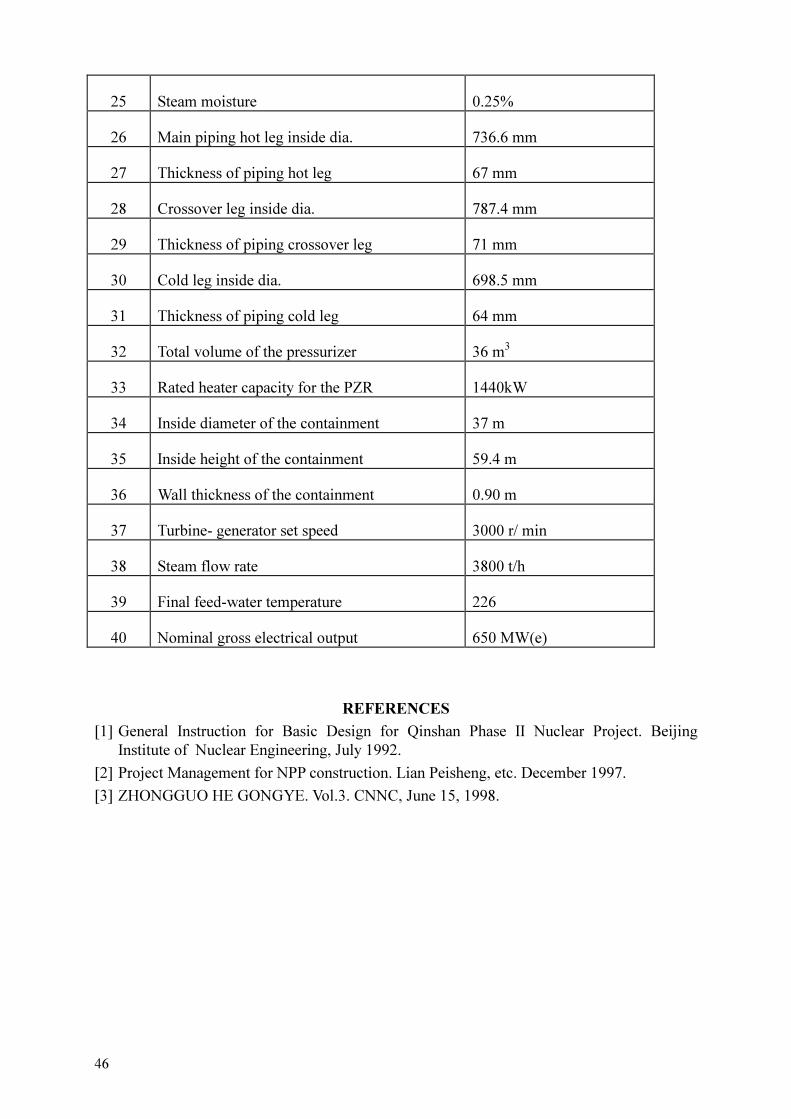
46
25 Steam moisture 0.25%
26 Main piping hot leg inside dia. 736.6 mm
27 Thickness of piping hot leg 67 mm
28 Crossover leg inside dia. 787.4 mm
29 Thickness of piping crossover leg 71 mm
30 Cold leg inside dia. 698.5 mm
31 Thickness of piping cold leg 64 mm
32 Total volume of the pressurizer 36 m3
33 Rated heater capacity for the PZR 1440kW
34 Inside diameter of the containment 37 m
35 Inside height of the containment 59.4 m
36 Wall thickness of the containment 0.90 m
37 Turbine- generator set speed 3000 r/ min
38 Steam flow rate 3800 t/h
39 Final feed-water temperature 226
40 Nominal gross electrical output 650 MW(e)
REFERENCES
[1] General Instruction for Basic Design for Qinshan Phase II Nuclear Project. Beijing
Institute of Nuclear Engineering, July 1992.
[2] Project Management for NPP construction. Lian Peisheng, etc. December 1997.
[3] ZHONGGUO HE GONGYE. Vol.3. CNNC, June 15, 1998.

47
EXPERIENCES AND LESSONS LEARNT ON STAFFING FROM
THE FIRST INDIAN NUCLEAR POWER PLANT (PHWR)
A.S. BHATTACHARYA
Nuclear Power Corporation of India Ltd
V.S. BHAVAN,
ANUSHAKTINAGAR
Mumbai, India
Abstract
Three decades of operating experience in India has led to sustained high performance of NPP's.
The staffing modules and policies are standardised. The basic functions of operation, maintenance,
technical support and quality assurance are carried out by a team of 727 in-plant persons (for a
2 � 220 MW PHWR station) organised at five levels, for fifty positions in ten job families. Specific
qualification levels apply to each position — six at management positions, five licensed positions
with the rest qualified through an equivalent training scheme. Practically all O&M activities are
carried out on-site by the utility manpower with minimum involvement of contractors. The entire
process of human resource development is in-house — with each NPP organisation comprised of 30%
experienced staff transferred from older NPPs and 70% totally developed out of fresh recruits. Four to
eight years lead time goes to qualify fresh recruits depending on the position. This optimisation of
manpower is a result of continuous learning — through operating experience and regulatory feed back
and self assessment for (i) optimising quantum of work load and (ii) improving productivity. For the
first category, design improvements over older NPP's increased reliability, operability, maintainability
and human factors and are described separately in the companion paper. In this paper the organisation
factors are discussed, starting with the initial lessons that demanded improved management and
enhanced quality programmes and caused temporarily, high demand of staffing for bringing out new
systems. For e.g.: (i) attaining maturity of units; (ii) standardising training, retraining and cross
training and qualifications; (iii) job rotations; (iv) in service inspection of reactor components; (v)
quality audits. The experiences on subsequent optimisation of staffing levels are outlined.
1. INTRODUCTION
Productivity of NPP personnel is a key contributor towards optimising staffing. The
motivation for optimisation stems out of the fact that (i) larger the number, larger the risk of
human error and (ii) larger number cannot make for lower competence. Assessment and
optimisation of staffing is thus, an assessment and optimisation of workload against this
expected productivity. The work-load is derived from the activities — both planned as well as
unplanned in the NPP, based on which standard staffing levels are worked out. Staffing levels
however change with time due to various separations, promotions and induction and
management approaches need to maintain the required profile dynamically.
The contribution of design towards optimising staffing has been discussed in a separate
paper.
In this paper we narrate our learning experiences since 1972 on the organisational
aspects for optimising workload, developing staff competence and maintaining staff profiles.
Table 1 shows the Indian Nuclear Power Programme.

48
Table 1. Indian Nuclear Power Programme
Unit Capacity Remarks
Tarapur Atomic Power Station (Taps
- 1 & 2) 2 � 160 Mw Commercial Oct. 1969 (Bwr)
Rajasthan -1 (Raps -1) Rajasthan -2
(Raps -2)
100 Mw
200 Mw
Dec. 1973
Apr. 1981 (First Of Phwr
Program)
Madras -1 & 2 (Maps) 2 � 220 Mw Jan. 1984 & Mar. 1986
Narora - 1 & 2 (Naps) 2 � 220 Mw Jan. 1991 & July 1992
Kakrapar - 1 & 2 (Kaps) 2 � 220 Mw May 1993 Feb. 1995
Kaiga - 1 & 2 (Kgs) 2 � 220 Mw Under commissioning
Rajasthan - 3 & 4 (Rapp -3&4) 2 � 220 Mw Under commissioning
Tarapur - 3 & 4 (Tapp - 3&4) 2 � 500 Mw Under construction
2. INITIAL EXPERIENCE WITH ASSESSING STAFFING
We will outline here our experiences with two major functions:
(i) operations and;
(ii) maintenance staffing.
2.1. Staffing for operations
Operation staffing is determined by manning points and factors depending on:
(i) NPP design, layout, locations and level of automation;
(ii) Regulatory needs of staffing;
(iii) Surveillance testing and maintenance support task;
(iv) Operational routines in the field;
(v) Operational services on site activities;
(vi) Shift structure, number of crews and leave reserve;
(vii) Training requirements.
We will examine here some of the operation factors and experiences.
2.1.1. Manning levels
PHWR’s need extra facilities and thus extra manpower e.g. for the following facilities
�� D2O additions, deuterations, resin ejections;
�� Dryer operations;
�� D2 O upgraders & accounting.
Most service systems are run on round-the-clock basis.
Table 2 shows the typical staffing including for control room.

49
Table 2. Typical shift crew composition in 1982 (raps)
Control room Field operation
(Main systems)
Total
Shift charge engineer = 1
Asst. shift charge engineer = 1
Control engineers = 3
Assistant/operators = 2
Field engineers = 2
Operators
�� Turbine building = 2
�� Reactor building = 2
Area operators
�� Switchyard = 1
�� Turbo generator = 3
�� Reactor system = 3
�� Chillers = 1
�� Standby power = 1
�� D2O Upgrader = 1
�� Isolations = 1
24 per crew
(9 Engineers &
15 operators)
2.1.2. Continuing training needs and number of shift teams
Number of shift crews have increased from four to five to six now. Round the clock
operation of NPP’s on all days of the week including holidays requires at least four teams.
However, to cater to sickness and annual leaves of operation staff, as also, to provide for
regular on the job training and upgrade training, at least five teams have been in existence
since 1987. Each of these five teams comprise of only the minimum manning level per shift as
approved and therefore NPP has to draw leave substitutes only from the general shift. In the
early eighties e.g. at RAPS, each of the shift team comprised of about 30% more than the
minimum shift complement but number of shift teams was limited to 4.5 only.
Operators have a structured training and qualification program and to provide for this
lead time (ranging 4 to 8 years for a fresh recruit), an additional strength of total 19 operator
trainees was sanctioned at RAPS. Subsequently, based on internal and regulatory reviews, the
NPP’s implemented the following mandatory practices :
(i) the syllabus and procedures for licensing tests were upgraded which demanded more
off the job training time.
(ii) Continuing training focussing on event analyses and refreshers was imparted to each
crew.
This led to five shift teams (as against 4.5) without any floating reserve in the team.
While this allowed more systematic and planned training activities, the staffing shortages
reappeared in most NPP’s due to the following reasons:
�� transfer of licensed staff to upcoming stations for commissioning and operation;
�� enhanced scope of training of shift staff towards good practices, human skills development
and management development.
As a result, the number of shift teams has been raised to six with however, reduced
manning levels in each team.

50
2.2. Staffing for maintenance
Maintenance staffing requirements are influenced by
(i) number, type and reliability of equipment;
(ii) maintainability, access and walking distances;
(iii) regulatory requirements of surveillance and tests;
(iv) extent of contracting possible for overhauls, fabrications and repairs.
About 50% of NPP staffing is assigned to maintenance functions. The optimisation of
staffing in the NPP basically means, thus, optimising maintenance staff strength without
sacrificing safety and reliability. If equipment failures are brought down to a reasonable level
the workload and staffing straight way come down.
2.2.1. Workload estimation — issues
Assessing strength of staff in an NPP was not as straight forward as in a project. For
example, to calculate number of pipe welders needed in our construction project, the
productivity norm roughly could be 250 mm pipe dia per day. For a 2 � 220 Mw unit, the pipe
welding workload works out to 1 00 000 metres to be completed in about 3 years; then about
50 welders need be hired. To maintain same amount of piping and equipment the number of
welders will have to be worked out however, using a different criteria :
�� how many different welding procedures for different metals and techniques exist in the
NPP;
�� how to keep welders continuously qualified and requalified on their specialised areas of
welding during normal operation by mockups and test pieces;
�� training needed to work on the equipment with all safety procedures and protective
clothings etc;
�� redeployability of highly skilled O&M welders through training for their career after
attaining age of 45 years when their hand eye co-ordinations are not as before.
In a typical two unit Indian NPP', the principle of assessing maintenance staffing are as
follows:
�� in the initial stages of NPP, the workload was stated as IP+B with P as preventive
Maintenance load and B the breakdown maintenance. As the plant matures with more
surveillance the staffing is worked out as 2P+IB. This implies attaining high “Meantime
between failures” and low “Mean-time to repair”;
�� about 60% of workforce is assigned to " in-situ" or field maintenance duties, 25% on
planning and records and rest on workshop (fabrication, tests, calibration, repairs etc.). See
Table-3 as a typical illustration;
�� staff must be trained and qualified so as to be rotatable from field duties to shop duties or
from reactor systems to secondary systems. A token number of tradesmen is also assigned
round the clock shift maintenance duties for urgent /routine tasks;
�� extent of contracting is limited to only major overhauls.
It is therefore essential that NPP maintenance staff must be managed keeping job
rotation in mind. This needs a multiskilling approach in maintenance training and also
ALARA provisions and practices.

51
Table 3. Break up of allocation of maintenance manpower
Sl.no. Section % allocation of manpower
Field Shop Supports
1. Mechanical maintenance 50 % 25 % 25 %
2. Electrical maintenance 72 % 20 % 8 %
3. Instrumentation maintenance 70 % 25 % 5 %
2.2.2. Improved planning for productivity
During 1983–1984, a series of brainstorming, sessions for improving productivity was
undertaken by NPP management at RAPS. In the context of manpower in maintenance the
following proposals were worked out.
Improved planning
(i) ensure timely availability of work permits (including radiological) by advance
application and dedicating operators and HPU staff for the issue of permits. Ensure
also receiving of permit, preparations of orders -to-operate (OTO) and conduct of OTO
are done in shifts so that isolations are available in day shift : ensure availability at the
same time tools, right materials, and protective clothing as also correct mix of crew
including riggers;
(ii) store work procedures for repetitive work including time measurement data as e.g.
"reactor coolant pump seal replacement";
(iii) improve, by training on supervisory skills the field supervisors and encourage
engineers to visit work spot regularly.
2.2.3. In-service inspection
By the late eighties, a standardised, much enhanced in-service inspection (ISI)
requirement was documented. The principles laid down for assessment of staffing were as
below:
�� the work included besides others, ultrasonic testing of all reactor coolant header / piping
joints (over 500 nos. above 100 mm dia) in 10 years; similarly in moderator systems. Also
eddy current testing of heat exchangers tubes in nuclear systems;
�� reactor channel creep thinning, sag and gap measurements;
�� special tools and instrumentation development for remote operation.
Even though the group needed highly skilled staffing in sophisticated NDT techniques,
the issues that posed challenges were
�� absence of suitable vendors with above know-how and with ALARA skills;
�� highly skilled staff had to be dedicated to In-service inspection who were fully engaged
only during shutdowns. This is so as during normal operations a separate group looked
after routine quality control jobs such as welding inspection, welder qualification, pump
seal inspection and turbo generator rotor inspection;
�� the ISI shutdown jobs also need meticulous dose planning and care to avoid equipment
getting contaminated.
It was therefore decided to have an ISI wing and a QC wing under QA/QC group. The
ISI group is organised around the specialised skills needed while more interchangeability
exists among QC personnel. The following staffing levels are typical:

52
Engineers = 05
Supervisors = 09
(technicians)
Tradesmen = 14
--------
Total = 28
=====
2.3. Remarks
Based on all above strategies, the operation and maintenance manpower has now been
standardised along with other functions.
3. EXPERIENCE WITH HUMAN RESOURCE MANAGEMENT (HRM) ASPECTS
Assessment of staffing levels has to be based on certain productivity of staff and their
development of attributes identified as “responsibility”, “quality” and “competence”. To
achieve this goal, the HRM needs to ensure:
�� quality of planning;
�� quality of training;
�� quality of follow up.
3.1. Quality of planning
Good planning needs three inputs:
i. frozen staff strengths and entry level qualifications;
ii. time of placement of identified staff and;
iii. method of recruitment.
3.1.1. Experience in the first PHWR station
During early seventies, the first PHWR two unit station at RAPS was expected to be
operated with 342 persons. Table 4 shows that this figure steadily rose to 859 by 1979. In the
absence of a standardised staffing level, the constant emphasis was only in inducting new
recruits in increasingly large numbers. There was an unattended but burning need to formulate
manning norms, recruitment and training policies and develop infrastructure for post-
employment training.
An attempt was made to recruit experienced O&M personnel from conventional plants
and process industries. As the following statistics shows, the response was poor and the
practice of recruiting from open market had to be discontinued in all NPP’s. See Table 5.
The reasons why external recruitment was not successful were as follows:
(i) demand of high quality leading to higher standards of recruitment;
(ii) remoteness of the NPP site as compared to conventional industries located in cities or
near cities;

53
(iii) long nuclear training programs with contractual obligations ; fear of over-
specialisation in nuclear field with reduced chances for change of job in outside
market;
(iv) housing shortages due to presence of large construction workers at peak of their
activities.
Table 4. Increasing staffing levels in the first PHWR Station (raps)
Sl.no. Year Standard strength
permitted
In position Fresh trainees
1. 1970 342 214 -
2. 1971 342 310 -
3. 1972 342 342 -
4. 1973 500 396 -
5. 1974 500 441 43*
6. 1975 731 548 99
7. 1976 731 650 113
8. 1977 731 679 87
9. 1978 731 705 68
10. 1979 859 742 89 * Stipendiary Training Scheme started.
Table 5. Shows response to open recruitment in 1970
YEAR
No. of
applications
seeking the
job
No. Called
for test &
interview
No.
Attended
the test &
interview
No. selected
No. joined
Remarks
1970 1029 235 159 46 31
1971 543 204 153 46 23
1973 1446 137 66 24 19
A decision therefore, to build nuclear training centre’s (NTC’s) and to start in-house
induction, training and qualification of O&M personnel out of fresh candidates from colleges
were taken in 1974. The scheme, called stipendiary training scheme (for engineers/scientists,
supervisors and tradesmen) has been since then the major source of NPP manpower in India.
Recruitment planning, as already mentioned, has to be co-ordinated with training planning as
per capacity available.
3.2. Quality of training
Nuclear Power Plants (NPP’s) need staff with high degree of “responsibility”, “quality”
and “competence”. At any phase or point of time, collectively NPP personnel must have all
the skills needed to attain the NPP goals. The human resource development policies are
established with a view that future performance will largely be achieved with today’s people.
The staffing requirements are greatly influenced by the quality of training imparted. Increased

54
emphasis on on-job training, re-training, human factors training and managerial skills
development would be possible only if:
�� initial training, on the job training and retraining are planned so as not to overload
training centres with clear policies on what need to be in centralised training and;
�� training resources of simulators, mock ups, manuals and trainer development are
planned in advance.
We have now four centralised nuclear training centres and a station training centre at
each station. Policies and special training services are provided by the corporate training
group including home grown systematic approach to training (SAT) methodology.
3.2.1. Impact on staffing plans
Needless to say, assessment of staffing takes into account that:
�� Human resources at all level will be away from job for initial training at other NPPs and
continuous training for about two months per year later;
�� Dedicated duly qualified trainer and support staff will be needed at each NPP;
�� Only after a lead time varying from four to eight years, a trainee will mature as a qualified
professional and during this period additional NPP staff for supervising them will be
needed.
3.3. Quality of follow-up
Quality of follow-up aims at retention of trained NPP personnel and at maintaining the
human resource profile despite changes of separations, ageing and re-deployment of human
resources.
3.3.1. Career planning
For retention, certain career policies link individual aspirations to NPP needs:
�� Continuous, non-vacancy based but appraisal focussed promotion to higher pay scales for
same NPP jobs within a cluster of jobs;
�� Additional salary for acquiring licensing based qualifications and career;
�� Opportunity to tradesmen and technicians to acquire professional qualifications in
engineering and then to obtain higher positions;
�� Assistance on science fundamentals to experienced technicians to acquire licensing based
qualifications at engineer level;
�� Opportunity to engineers to take senior positions in another new NPP or in headquarters.
The idea is not to loose experienced and skilled staff. However, the above do create
additional inputs to human resource planning as the profile gets changed by induction from
lower levels by promotions as well as by transfer of experienced staff.
3.3.2. Replacements planning
Delays in commissioning of some of our projects, led to loss of young trained
professionals - sometimes about 15 in one year. It is hard to replace them, as it takes about
four years to get qualified to the first position. Additionally, the tradition of taking large batch
of fresh trainees also now create a new problem - of large scale retirement too at one time.

55
This (retirement) being an age dependent event, it happened to both engineers as well as
technicians. Thirdly, certain senior and critical positions are filled in a new NPP only by
transferees from older stations, who must be positioned in the new NPP so that they re-qualify
for the new position. Simultaneously, replacement trainees in the older NPP must be
positioned well in time. Thus, the dynamically changing profile of human resources need to be
controlled by close follow up. Some measures adopted by us are:
�� train and qualify about 10% extra i.e. over and above vacancies among engineers;
�� license and deploy trainees of new NPP in a similar older NPP to also provide temporary
replacement of separating transferred staff;
�� continuously fill vacancies of technicians and train — no extra staffing is allowed though.
3.3.3. Retention & makeup needs
However, extra staffing does not always lead to required competence, as training and on-
job experience opportunities get divided now among larger number of trainees. The only way
to make human resource planning effective is to make unplanned separations as low as
possible so that make-up needs are either small or predictable so as to avoid negative effects
of separations. We have atleast three NPP’s with this low-separation feature.
3.4. Remarks
The next section gives the current status on organisation and staffing.
4. CURRENT ORGANISATION & STAFFING
4.1. Organisation
Figure 1 shows the standard qualification based five level organisations for four basic
functions:
(i) Operations
(ii) Maintenance
(iii) Technical services
(iv) Training
4.2. Standard strengths
The staff in NPP are categorised as:
(i) Engineers/
Scientists
(professional engineering degree holders or masters in science)
(ii) Supervisors (three year engineering diploma holders after twelve years of
schooling)
(iii) Tradesmen (ten years schooling plus vocational training of 2 years or
twelve years of schooling with science and mathematics)

56
SD
CS
OS
SCE
ASCE
CE
FO
SO
MS
SME
M/E/I&C/FH
ME
AME
MSp.
Mntr.
TSS
STE
TE
ATE
STA
Techn.
PHYST. /CHEM.
AP / AC
SSA
TS
TO
ATO
TI
Techn.
LEGEND :
SD - Station
CS - Chief
OS - Operation
MS - Maintenance
TSS- Tech. Service
TS - Training
SCE- Shift Charge
ASCE- Asst. Shift Charge
CE- Control
FO- First Operator
SO- Second
SME- Senior Maintenance
ME- Maintenance
AME-Asst. Maintenance
MSp.- Maintenance
Mntr.-Maintainer
STE- Senior Technical
TE-Technical
ATE-Asst. Technical
STA.- Sr. Tech.
Techn.-Technician
PHY/CHEM- Physicist /
AP/AC-Asst. Physicist /
SSA- Sr. Scientific
TO- Training
ATO- Asst. Training
TI- training
Management
Position
Functional
Qualification I
II
III
IV
V
FIG. 1. Operation & maintenance organization.

57
Table 6 the standard staff strengths by function and category.
Table 6. Standard staff strengths (2 � 220 MW NPP)
Sl.no. Function Engineers Supervisors Tradesmen Total
1. Management 05 - - 05
2. Operation 54 30 107 191
3. Fuel handling 12 18 30 60
4. Control
maintenance
12 18 45 75
5. Electrical
maintenance
10 15 50 75
6. Mechanical
maintenance
15 25 100 140
7. Technical unit 30 30 20 80
8. Training 09 06 06 21
9. Health physics 04 20 20 44
10. Waste management 01 05 30 36
Total 152 167 408 727
4.3. Standard recruitment planning
One year, before scheduled criticality of unit-1, 75% of the total technical staffing must
be in position. Rest 25% have to be in position before criticality of unit-2.
Source of manpower
Seventy percent of the total strength are recruited as fresh trainees and trained in O&M
construction and commissioning activities. Rest 30% positions are manned by transfer of
experienced personnel from older NPP’s for senior positions as well as from the local
construction group.
Lead time of recruitment
Recruitment of trainees must start four years before criticality @ 25% per year. They
need to go through intensive induction nuclear training ranging from one year to two years
before undertaking on job training for licensing/qualification programmes.
Training capacity
A maximum of 75 trainees, engineers, supervisors and tradesmen at one time, are put on
training at nuclear training centre’s (NTC’s) in different disciplines of operation &
maintenance (O&M). This will then not overload the theoretical, practical and field training
programmes. Installed training capacity therefore, limits the recruitment size and backlogs are
avoided by co-ordinating recruitment with training centres.
Educational qualifications
The new recruit must have entry level standard education such that he can secure the
highest level of station qualification in his category. For example an engineer trainee needs to
reach up to shift charge engineer /senior maintenance engineer /senior management positions
and must therefore, have a bachelor of engineering university degree.

58
On the job training
Commissioning, operation and maintenance in older NPP’s or home NPP’s and
obtaining licenses and qualification as in Figure 1.
Regulatory requirements
Appointments to management positions, shift charge engineers, assisstant shift charge
engineers, control engineers both in main plant as well as refuelling operations are done under
direct surveillance of the regulatory board.
For all other positions, the Regulatory board audits the training and qualifications
programme for ensuring the competency needs for safe operation.
5. CONCLUDING REMARKS
The experiences from the first PHWR station in India during its initial operation
provided valuable feed back for developing competence, improving productivity and retaining
qualified human resources. Not only this first NPP attained maturity for subsequent high
performance, it also standardised manpower packages for future NPP's. This paper examined
the initiatives taken by NPP management towards organisational improvements. The design
improvements are narrated in a separate paper.

59
INFLUENCE OF DESIGN IMPROVEMENTS IN
OPTIMISING STAFFING OF NPPs — AN INDIAN EXPERIENCE
A.S. BHATTACHARYA
Nuclear Power Corporation of India Ltd
V.S. BHAVAN,
ANUSHAKTINAGAR
Mumbai, India
Abstract
Three decades of operating experience in India has led to sustained high performance of NPP's.
The staffing modules and policies are standardised. The basic functions of operation, maintenance,
technical support and quality assurance are carried out by a team of 727 in-plant persons (for a
2 � 220 MW PHWR station) organised at five levels, for fifty positions in ten job families. The
organisational factors that led to optimising of staff are described in the companion paper. This
optimisation of manpower is a result of continuous learning — for (i) optimising quantum of
workload and (ii) improving productivity. For the first category, design improvements over older
Indian NPP's have increased reliability, operability, maintainability and human factors. Few examples:
(i) improved man–machine interface in plant controls and on-power refuelling system with operator
guidance, logging as well as diagnostic/health monitoring features; (ii) spread out layout for better
access and ease of maintenance, separation of plant services for unit-1 from unit-2 and, removal of
reactor auxiliaries out to separate buildings; (iii) reduction of maintenance tasks through redesigned
equipment and improved condition monitoring means. However, design and procedural improvements
also include additional equipment for upgradation of safety measures e.g. larger number of safety
related pumps separate switchyard control room and increased service system equipment. This paper
outlines experience of design improvements in optimising staffing and uses a specific case illustration
to establish the findings for better use of staff.
1. INTRODUCTION
Assessment and optimisation of staffing is basically an assessment and optimisation of
workload against certain expected productivity. The workload are derived from the design and
human activities — both planned as well as unplanned in the NPP productivity of NPP
personnel is a key contributor towards optimising staffing and design needs to keep in view
the risk of human error for various activities. Productivity is also influenced by the
environmental constraints such as ALARA needs, layout, accessibility and ease of working.
Design contributes greatly towards improvement of workstation.
Optimisation of workload can be made possible at source level by suitable design and
operation measures to minimise failures and outages which create unplanned work. However,
such measures do create certain additional programmes of surveillance, monitoring, training
and quality assurance to create additional planned workloads. Design improvements,
therefore, seek to create net reduction of unplanned workloads while supporting productivity
improvements.
2. TYPICAL DESIGN IMPROVEMENTS TO IMPROVE PRODUCTIVITY
2.1. Improved man–machine interface and automation
2.1.1. Reduced workload
The increased level of automation reduced response time and quality of decision making
of operation staff, e.g.

60
(i) Transients handling needed 15 to 20 alarm handling within 2 to 5 seconds in older NPP.
Computers now indicate “the first out” alarm, greatly facilitating diagnosing the fault.
This even saves "poison-outs”. Outage reduction directly reduces workloads and staffing
requirements;
(ii) Computerised reactor protection system such as Programmable Digital Comparator
System eliminates electromechanical relays and alarm indicators with password
controlled setting changes. This also reduced spurious trips substantially. Similarly
control room computer system (data acquisition system) has substantially reduced strip
chart recorders, analog-meters and relay annunciators, reducing operations as well as
maintenance workload;
(iii) The operators are able to successfully and productively interact with the computer
system on its structured inputs and outputs, its prompts, diagnostic messages and help
menu and are thus more productive. For example, detection of and exact locations of
occurrences e.g. of fire, D2 0 spillage have been made easy and less time consuming.
2.1.2. Cultural factors
The success of computerisation in improving productivity however had been dependent
on certain attitude factors e.g.:
�� if sensors picked up noise and caused chattering, the computer should not be blamed by
operators;
�� maintaining logs only on computers as a culture and not on papers also as options;
�� not looking for extra staff for keying in log information.
2.2. "ALARA" by design changes
Minimising individual and station doses to implement ALARA have been one of the
important design goals. The examples of measures adopted in design of NPPs are given
below. All such measures are also effective in reducing outages, breakdowns and therefore
reduced man-hours of maintenance.
2.2.1. Selection of materials
At NAPS /KAPS and 500 MW(e) units, mushroom type steam generators have Incalloy-
800 tubes with less percentage of nickel. This has substantially lowered radiation field due to
cobalt-60. Also the reactor vault is water filled with no air present and this eliminated Argon-
41 activity.
2.2.2. Separating radioactive areas and spread out layouts
Nuclear auxiliaries such as auxiliary cooling purification systems and D2O recovery
dryers have been located in a specially ventilated separate building away from main reactor
coolant and moderator system. This enables optimisation of space around reactors too. Also at
RAPS/MAPS, emphasis on compactness to reduce heavy water hold up had resulted in a
moderator room where there is hardly any space left for maintenance. With deletion of
equipment for moderator dumping system for reactor trip, further space is available e.g. for in
service inspection of moderator heat exchangers.

61
2.2.3. Minimising leak
The D2O systems contain tritium and gamma activity. To minimise spread of activity
some of the design measures taken in the moderator system from NAPS onwards are
(including 500 MW(e) units):
�� reduction of number of flanged joints from about 170 per unit (at RAPS) to about 34;
�� use of flanged butterfly valves at RAPS is replaced by welded gate valves for better
isolation and diaphragm valves by bellow sealed valves;
�� reduction of number of valves, from about 200 per unit (at RAPS) to about 100.
2.3. Design demanding additional workload (new NPP’s)
Enhanced safety requirements have brought in following design changes in the newer
NPP’s under construction e.g. at Kaiga and RAPP-3&4.
�� Additional safety related pumphouses and firewater pumps and additional (unitised) fuel
loading and transport equipment. Additional operational and maintenance surveillance are
called for;
�� Separate buildings for the two turbine halls, separate diesel generator building, separation
between unit-I control panels from unit-2 panels in main control room, separate
(electrical) switchyard control building. These will increase walking distances and call for
additional manning points for operators. To illustrate, in case of transients such as line
tripping or power failure, all alarms, relay flags, communications with grid authorities
and operations of 220 KV controls will have to be done in the switchyard control room —
remote from control room.
2.4. Remarks
The next section provides in a case study on on-power refuelling system design
improvements for optimising staffing.
3. CASE STUDY: EXPERIENCE WITH FUEL HANDLING SYSTEM STAFFING
3.1. Background
3.1.1. General
Fuel handling system does on-power refuelling and handles radioactive spent fuel from
the reactor for safe transfer to the storage bay. All operations are to be done remotely and
safely as the equipment are located in inaccessible areas. The fuelling machines home-on to
the reactor channels, remove plugs, load fresh fuel at upstream end and receive spent fuel into
the fuelling machine at downstream end. The fuelling machine is then moved to fuel transfer
system for exchange of spent fuel for fresh fuel and transfer system to the spent fuel storage
bay. The sequential operation logic of the machines is organised into sequences comprising of
a number of programs executed stepwise. Each step consists of a logical combination of
permissive which permit execution of a set of commands. The step is done, when the
feedbacks indicate a successful execution of the commands. The basic goal or challenge lies
in completing the channel operation in minimum time without compromising safety and
quality.

62
3.1.2. Problems and issues
In the early eighties, at RAPS / MAPS, the fuel handling operators had a tough job. They
relied more on their observation on the operators console and recorder charts for analysing
causes of equipment failure and events and corrective actions. For example, whenever there
were problems in removal of the plugs, the operator intervened manually through operator
console, for executing all sequential steps. There were chances of diagnostic delays and errors.
There were at times, over 70% downtime of the machine with only particular components
failing repeatedly. Absence of systematic training in fuel handling discipline at that time,
difficulties in planning preventive maintenance as well as non- availability of custom-built
spares became serious bottlenecks. The only way to meet refuelling needs was to increase
both operation and maintenance staff strengths and do two-shift operations for refuelling.
3.1.3. Staffing increases
At RAPS in eighties the repetitive, sequential and strenuous panel operations coupled
with frequent problems with field devices led to large amount of manual operations and
continuous supervision. A typical crew then would comprise of
��One fuelling engineer (per crew);
��One control panel operation (per unit per crew);
��Two assistant operators;
��One area operator for spent fuel bay.
Two crews did fuelling
For two units and three crews therefore, the fuelling staff comprised of
3 Engineers
6 Control panel operators
12 Assistant operators
6 Area operators
---------------------------------
Total = 27
---------------------------------
Refuelling group is an autonomous group with its own operation, planning, analysis and
maintenance group. For planning and technical support another 10 persons were needed
bringing the total to 37 operations. However, in the early stage, the fuelling machine
component failure rates were extremely high giving a down time of about 50%. So the staff
was divided equally between operation and maintenance giving a total of 37+38 = 75 for
refuelling crew. This was later raised to 93 to meet the requirements of continuous unit
operation.
3.1.4. Initial experience at NAPS on new system
Subsequently systematic training programs were introduced at all NPP's for fuel
handling personnel. However, introduction of a new computerised system at NAPS with
redesigned fuel transfer system created some teething troubles during commissioning e.g., to
readjust various cards (on gains, non-linearity etc.), modify software (in e.g. accuracy check
bands, delays on device operations) as also testing on integrated system. This new system
demanded additional commissioning staffing for various readjustments including fuel transfer
systems.

63
3.1.5. Design and systematic changes later
Subsequently, at NAPS, KAPS, the fuelling performance improved. The refuelling time
came down to just under 2 1/2 hours, with the system operating on auto 80% of the time and
maintenance time taking only 15%. What is equally significant is that we could bring down
and standardise staffing levels also for KAPS. At RAPS / MAPS also, design improvements
on site (e.g. relocating leak detector valves away from inaccessible, high gamma area under
the snout in the fuelling machine head reduced maintenance time), systematic maintenance
planning (e.g. replacing periodically the ball valve seals drastically brought down seal failures
in fuel transfer room) and formal training and certification of fuel handling staff improved the
performance substantially at all levels.
The next section outlines specific examples of design improvements in NAPS onwards.
4. SPECIFIC IMPROVEMENTS — OPERATIONS
The new design of man–machine interface computer controls and process design at
NAPS / KAPS have substantially reduced operator workload at the same time improved their
productivity and supports. Some examples:
4.1. Man–machine interface
4.1.1 Automated device positioning
Auto positioning needs very skillful manual operations e.g. for positioning the fuelling
machine carriage on the required reactor channel. In the computerised fuel handling system at
NAPS / KAPS, this positioning is done by the micro-computers. The operator selects the
channel location; the program number and program logic, the fuel bundle and rest are done
automatically. They also read digital panel meters which do not strain eyes for monitoring
long travels on dial type meters.
4.1.2. Automated error /mismatch detection
For refuelling, the operator must have full status information. At RAPS / MAPS, if e.g. a
reference potentiometer slipped, the fuelling machine could home on to wrong channel and
this could be known only when second pair of bundles were being pushed. Considerable man-
hours could get lost. At NAPS / KAPS, this matching is done by the computer.
4.1.3. Guided problem solving
The reason for any “HOLD” appears on the display, thus avoiding diagnostic errors.
Even if the operator decides to bypass a certain interlock, there is no need to “jumper” and
with a risk to forget to remove the jumper later. He now only presses “skip” button for every
bypass. Operators therefore now concentrate more on monitoring, rather than diagnosing,
checking and manual logging.
4.2. Reduced cycle time due to process design
At RAPS/MAPS, at one time, only two spent fuels can be discharged to fuel transfer
port. Also at that time, new fuel loading cannot be done. In subsequent designs, all eight
bundles can be discharged at one time in just half the time, simultaneously new fuel can also
be loaded in the fuelling machine head. Also NAPS has separate spent fuel receiving stations

64
for each reactor. So, simultaneous transfer of spent fuel to bay for storage from both reactors
is possible.
5. IMPROVEMENTS IN MECHANICAL MAINTENANCE ACTIVITIES
The following examples illustrate measures that reduce maintenance workload and
maintenance time.
5.1. Human engineered design
Examples are:
(i) Installation of the Ram assembly was very difficult at RAPS / MAPS / NAPS, as its one
part “ball screw” was assembled in ram housing, while its mating ball nut was placed in
magazine housing. The points here are two i) any mismatch in alignment here could jam
the ball screw assembly and ii) during disassembly for doing maintenance it would take
considerable time to take out ball nut from magazine thus increasing maintenance time.
At KAPS the redesigned ram housing houses the ball nut also and makes assembly /
disassembly much simpler; further more, the ram assembly has been relocated at a
convenient working height which improved quality of maintenance;
(ii) In the fuel transfer system, transfer magazine and shuttle transfer tube are physically
separated by having two valves with a gap to avoid accidental mixing of D2O with
H2O.
5.2. Towards simplification and ALARA
Some examples are:
(i) At RAPS/MAPS, the fuelling machine service area is separated by a complex door
(carriage access door). At NAPS, therefore the service area is provided underneath
fuelling machine vault totally isolated from other accessible areas to facilitate
maintenance and adjustments. The design is considerably simplified with much reduced
number of components in e.g. cable carts, carriage, etc.;
(ii) A special service cart is provided to lift and lower the fuelling machine head for
assembly and disassembly;
(iii) Supported fuelling machine columns and bridge structures are less complicated, easier
to manufacture (and therefore to maintain) and do not demand high accuracies as in the
older NPP's;
(iv) Oil hydraulic panel and power units are located in accessible areas to facilitate
adjustments, maintenance and trouble shooting;
(v) The number of equipment new fuel passes through before reaching the fuelling machine
and the number of times the bundle negotiates the ball valve have been substantially
reduced almost to half of those in older NPP's.
6. IMPROVEMENTS IN CONTROL SYSTEM MAINTENANCE
The reduced hardware, more reliable hardware and computerised maintenance aids have
improved productivity, reduced workloads and maintenance time. Some examples:
6.1. Maintenance free hardware
Since computers do most positioning of devices, there is a substantial reduction in
conventional relays type hardware, limited to only few manual logic cards for emergency

65
operations. Use of standard logic gates with much higher packing density further reduced
hardware while improving reliability. Also there are just nine LVDT’s (linear variable
differential transformers for sensing positions) and this reduced considerable calibration
workload. Use of single-turn potentiometers for Ram-C both coarse and fine, saved
considerable downtime due to over-travel of the wiper shaft of multi turn potentiometer when
the tape broke, in older NPP's.
6.2. Guided trouble shooting
The position of any field potentiometer can be checked right on operator console —
there is no need to go to field for maintenance checks. Similarly one can verify the
calibrations against tables stored in the computer.
6.3. Prompt diagnosis
Maintenance off line tests also check if pressing of switches is leading to intended
operations. There is no need to take electrical drawings and measure logic levels, unless there
are faults. Status of the control system including any system failure is directly indicated.
6.4. Reduced overall configuration
The system at RAPS / MAPS had voluminous wiring, huge floor mounted power
supplies and logic racks. There were more maintenance attentions needed obviously due to
higher heat dissipation, higher noise pick-up and distances involved. The compact system at
NAPS onwards have thus enabled control maintenance staff towards more planned activities.
Bringing out input / output connections on the front connectors of the logic boards and
extending their connections to the interface modules greatly reduced back-panel wiring and
noise pickup at NAPS. Use of switched mode cabinet mounted power supplies caused much
less heat dissipation problems.
7. IMPROVED SUPPORTS
Given below are few examples of improved supports by design efforts in the new NPP's.
7.1. Health monitoring aids
The computerised logging now provides report on e.g.:
(i) how much time each execution step took including causes of any delays permissives not
available and;
(ii) deterioration in performance of ram assemblies by correlating with their auto-
positioning time. This has enabled systematic preventive and predictive maintenance.
7.2. Operator error logging
Analysis of computerised logging of operator errors now provides an objective basis for
systematic monitoring of on the job training.
7.3. Operations training simulator
At Kaiga a replica fuel handling training simulator is being installed. The facility will
provide training on operations under all modes, failure conditions and error likely situations.

66
7.4. Calibration and test facility
In the upcoming 500 MW(e) NPP's, a light water facility is being provided for testing
serviced subassemblies such as ram assemblies and components like oil hydraulic valves.
Located in tritium-free area, the facility will provide for all fuelling machine head operations
as in a reactor. It will reduce downtimes and radiation doses as well as continuously impart
maintenance training to fuel handling personnel.
8. IN SUMMARY — BETTER USE OF STAFF
On power refuelling as just one typical example of NPP operation, employs complex
technology and demands very competent operation and maintenance. The experience feedback
to design and operation led to improved reliability, operability, maintainability and also
support towards higher productivity. These efforts have reduced workloads despite
upgradation of performance requirements and also improved productivity of people. As a
result staffing level has been optimised and brought down while maintaining high
performance. This was a case study to bring out role of design in optimising staffing and
making more gainful, enjoyable work life of operation & maintenance personnel in the entire
NPP.

67
STAFFING REQUIREMENTS FOR SMRs: THE SOUTH AFRICAN VIEW
W. ROSCOE
ESKOM,
Johannesburg, South Africa
Abstract
Eskom has, since 1993, been investigating ways of producing electricity at lowest possible cost
to its customer base. As part of this research, a concerted effort was made to investigate not only the
types of power plant but also their impact on the environment and the economy. The chosen route
followed was that of the Pebble Bed Modular Reactor. This is due amongst other reasons to its
economic power production; it’s lack of visual impact and the integral ‘walk away safety design’.
Eskom, along with it’s technology partners is now at the stage of drawing up the detail design for the
plant, in line with this design stage, cognisance has to be taken of the required synergy between man,
the plant design and it’s operability and maintainability.
1. INTRODUCTION
Eskom has learnt many lessons from the early days of operation of its Koeberg Nuclear
plant and in this regard has set specific objectives and performance targets for it’s new nuclear
power plant.
2. UTILITY EXPERIENCE WITH STAFFING OF NUCLEAR POWER PLANTS
2.2. It is important to understand that Koeberg is Eskoms only existing power plant and was
built as a turn key project. During the building of Koeberg there was intensive support
provided by the vendor and the French utility EdF. Eskom then staffed up the plant to a
level that was in excess of that one would normally expect at such a plant [± 1850] . The
reason for the over staffing was in support of processes such as:
�� Change control, that is the production of procedures and design changes etc.;
�� Large support staff such as Human Resources and documentation control.
Other reasons were related to the lack of experience and the ill defined boundaries
between site and corporate in the provision of corporate functions and interfaces.
2.2. The reduction of the staffing numbers was very difficult and was achieved over a period
of 6 years, various methodologies were used from the provision of early retirement
packages and other financial incentives, to methods related more to Industrial
Engineering, examples would be:
�� Improved planning of work and the required support structures;
�� Re assessing the frequency and or need for routine maintenance;
�� Improvements in outage planning, especially the control of contractors;
�� Reducing the need for large stores stock holdings and their related costs;
�� Recognising that support functions are not all nuclear specific thus centralising where
possible with other power plants;
�� Improved manpower planning.
2.3. Figure 1 reflects the current numbers for Koeberg and these reflect more accurately the
original staffing intentions.

68
Ops Main
t
Outage Prod Bus Finance Hum Nuc Nuc Info
Band Admin Res Eng Saf Ass Mngt Total Trainees
M/P/S
BAND 10 7 3 7 1 0 7 34 4 1 74
CU/PO
BAND 61 32 3 33 4 3 22 55 26 2 241 Appy 2
CL
BAND 33 91 2 42 5 0 12 15 9 1 210 E I T 1
CTL
BAND 0 2 0 0 0 0 0 0 0 0 2 G I T 0
BU # Further
BAND 21 68 0 38 6 1 3 0 6 3 148 Study 5
BL Young
BAND 7 60 1 35 24 0 6 13 10 20 176 Engineer 1
TOTAL 132 260 9 155 40 4 50 118 55 27 851 GATDP 2
8
A
BAND 0 0 0 0 4 0 0 0 0 0 5 Total 3
7
GRAN
D
TOTAL 132 260 9 155 44 4 50 118 56 27 856
# Power station Managers secretary included here
FIG. 1. Manpower staffing, July 1998.
2.4. The relationship between staffing costs and plant performance are not necessarily relevant
as can be seen in the following appended figure 2 and graph 1.
Year Rands Manpower costs MWh
per MWh 1997 Rand sent out
1986 14.35 126354785 8803000
1987 22.54 138982378 6167000
1988 14.04 147322793 10493000
1989 13.6 150980538 11099000
1990 16.89 142709402 8449000
1991 14.78 135112547 9144000
1992 14.62 135779552 9288000
1993 18.04 130540869 7236000
1994 12.28 118776779 9675000
1995 11.15 125771781 11282000
1996 11.22 131783831 11749000
1997 10.49 132404000 12627000
FIG. 2.

69
Graph 1. MANPOWER COSTS PER MW(h) SENT OUT IN MILLIONS
0.00
20.00
40.00
60.00
80.00
100.00
120.00
140.00
160.00
1986 1987 1988 1989 1990 1991 1992 1993 1994 1995 1996 1997
0
2000000
4000000
6000000
8000000
10000000
12000000
14000000
MANPOWER COSTS IN MILLIONS MWh SENT OUT
It should be noted that the reduction of staff at Koeberg down to what is seen as the
correct level was achieved without any negative impact on nuclear or general safety.
3. EXPECTATIONS OF STAFFING REQUIREMENTS FOR FUTURE SMR DESIGNS
3.1. Current status of the South African PBMR
Since 1993 Eskom has been investigating the potential of small, direct cycle, HTGRs to
meet long term energy growth away from the inland coal fields. The cost pressures on this
design are extremely tight and led to fundamental reviews of all costing areas, including
manpower.
The PBMR project is currently at the end of the concept/basic design stage and detail
design should commence in 1999. The current aim is to be in a position to commit to the
construction of the lead (or prototype) unit by the end of 1999.
As well as the engineering work, the programme is currently involved with the
Environmental Impact Assessment, the formal nuclear licensing process and discussions with
the National Electricity Regulator.
3.2. Purpose of the system
The purpose of the system is to generate electricity in a
�� safe;
�� environmentally friendly;
�� efficient, and
�� cost-effective manner.

70
by:
�� maximising the benefits due to the inherent safety characteristics of the pebble bed
reactor concept;
�� maximising the use of proven technology (including that for the fuel fabrication);
�� following a modular approach (to enhance licensing and series production);
�� designing for ease of operation and maintenance by a minimum number of personnel;
�� designing for maximum international marketability.
3.3. Safety, economics, marketability]
The classical systems approach towards addressing ergonomics during design implies
that functions are separated and allocated between human and machine. At this stage the depth
of information available on the system functions for the PBMR is inadequate to perform a
classical allocation of functions to the human. This is due to the fact that no formal functional
analysis (with an increase in functional detail) has been performed.
Allocations of system functions to machines have been implied, through the
extrapolation from general practice and/or based on engineering principles/decisions. The
approach to the ergonomics contribution therefore had to be adapted to allow for this.
3.4. Approach followed
The following ergonomics issues have been addressed:
�� A high-level statement of system objectives was formulated;
�� Typical high-level tasks and human task performers were identified which allowed a
postulation of the potential role of the human in the system. For a first iteration a high
degree of automation was assumed.
Fundamental assumptions are that the inherent safety characteristics of the plant are such
that safety cannot be compromised by any human intervention / omission; the impact if any
will merely be on the availability of the plant.
3.5. Potential role of the human in the system
Degree of human involvement:
h0: do nothing / absent;
h1: monitoring and assessment;
h2: dynamic replanning;
h3: intervention and control;
hi: initiate.
Level of automation:
a0: low (but includes protection functions - RPS & EPS);
a1: moderate;
a2: high;
a3: completely automated.
Notes: Fundamental assumption:
(i) Inherent safety characteristics of the plant are such that safety cannot be compromised
by any human action / omission; the impact will merely be on availability of the plant;

71
(ii) The level of automation for a user pertains to the functionality of the automation
system for the specific user (human);
(iii) Technical support refers to the support given to operators / supervisors by e.g.
engineers or other technical specialists;
(iv) The list of tasks is not comprehensive; it merely serves to illustrate the approach.
Other tasks could include: resource management - planning and scheduling - personnel
training - configuration management - quality assurance;
The following table shows a postulated degree of human involvement and level of
automation for typical high-level tasks and human task performers as discussed above.
4. DISCUSSION
The potential human role as indicated, shows a low degree of reliance on the operator
with higher levels of responsibility given to the supervisor and engineers. This may imply
drastically different levels of training for different personnel.
For the assumed high level of automation the human should be viewed as being in a
supervisory capacity. His role includes the following:
�� Monitoring that the automatic controls are functioning as intended;
�� Adjusting the reference points with respect to which the automatic controllers are
regulating the processes.;
�� Optionally intervening during failures and emergencies.
The two potential impacts upon system risk are human reliability and human error. If it
is accepted that no human action or omission can put the plant into an unsafe situation, the
potential for emergency conditions due to human error is largely eliminated. This will
consequently benefit human reliability within the system and improve system performance.
Staffing levels derived from the system objectives implies no more than a couple of
operators with a single supervisor for normal operational conditions. The number of operators
available per shift would not be in a position to monitor and control the power generation
process on UNIT level without the support of and reliance on an automated process control
environment. In any event monitoring and control tasks will have to be implemented on a
high task level rather than a sub-system hardware level.
The definition regarding the level of automation may be expanded to distinguish
between automation for control (open-loop and closed-loop) and information / monitoring.
The different levels could then be a0 to a3, and m0 to m3 respectively (where m0 could
correspond to a very primitive level and m3 to high level of abstraction with respect to
monitoring).
5. PROPOSED METHODOLOGY FOR ERGONOMIC DESIGN
The following sequence of steps [Fig 3] is suggested for the ergonomics design. The design
should happen as a number of iterations of this sequence, the detail becoming clearer with
successive iterations. For the initial iteration(s) where depth of engineering on the system
level is limited, some items indicated in the sequence will be omitted or only be done
partially/tentatively.

Humans
Op
era
tors
Su
perv
iso
rE
ng
ineers
Main
ten
an
ce
Pro
du
cti
on
man
ag
er
Tasks
Norm
al
opera
tion
Abnorm
al
opera
tion
Norm
al
opera
tion
Abnorm
al
opera
tion
Norm
al
opera
tion
Abnorm
al
opera
tion
Norm
al
opera
tion
Abnorm
al
opera
tion
Norm
al
opera
tion
Abnorm
al
opera
tion
MO
DU
LE
level
Reco
mm
issio
nin
g
Pro
ve in
tegrity
h0
---
h0
---
h3
/a0
---
h1/a
0--
-h1
/a0
---
Sta
rt-u
p (
to h
ouse load)
h0
h0
h0
h0
hi h1/a
3h3/a
0h1/a
0h1/a
0hi h1/a
0h1/a
0
Op
era
tio
nal
Loadin
g (
inclu
din
g c
onnecting to g
rid)
hi/a3
h0 h
1/a
3
h2/a
0 O
R
h1/a
1h1/a
3--
---
---
---
-h1/a
0h1/a
0
Pow
er
opera
tion
h0/a
3h0/a
3h1/a
1h1/a
3--
---
---
---
-h1/a
0h1/a
0
Shutd
ow
nhi/a3
h0/a
3hi h1
/a0
h1/a
3--
---
---
---
-h1
/a0
h1/a
0
Ma
inte
nance
---
---
hi/a0
---
h1
h2/a
0--
-h3/a
0--
-h2
/a0
---
Em
erg
ency s
hutd
ow
n--
-h
i/a0
---
OR
hi/a0
---
OR
hi/a0
No
n-e
ssen
tial ta
sks (
day-t
o-d
ay)
(als
o a
t U
NIT
level)
Identify
failu
res / incip
ient fa
ults
h1/a
3h1/a
3--
---
---
-
Handle
dis
turb
ances
h0 h
i/a3
h1 h
i(?)/
a3
---
---
---
Accid
ent m
itig
ation
h0
hi/a3
h1/a
3--
---
---
-
UN
IT level
Load s
chedulin
g--
-h1/a
3--
---
-hi h2/a
3
Long
term
he
alth
an
d s
afe
ty m
onito
ring
---
---
h1
/a0 a
1--
---
-
Incid
ent analy
sis
---
h1/a
0 a
1h1
/a0 a
1--
-h1
/a0 a
1
Technic
al support
[see n
ote
3]
---
(hi)
/a0 a
1h1/a
0 a
1--
---
-
Perf
orm
ance m
onito
ring
---
h1/a
2 a
3h1
/a0 a
1--
-h1
/a2 a
3
Auto
mation s
yste
m h
ealth m
onitoring
---
---
h1/a
3--
---
-
72

73
Sequence of steps for the ergonomics design *(note 1)
�� Analysis of processes
(e.g. operational processes)
�� Task definition and description
�� Task analysis *(note 2)
�� identify gross tasks
�� identify facilities required
�� identify tasks critical to system performance
�� do work-load analysis
�� determine staffing levels
�� determine required skills and training
�� determine task sequences
�� determine preliminary procedures
�� Ergonomics design
�� interfaces
�� workstations
�� facilities
Notes*
1. The analyses, definition and design should take into account the nature, features and restrictions of the
system- and subsystem- / mechanical design.
2. As part of task analysis the following should also be defined:
philosophies with respect to:
�� alarming;
�� control;
�� coding (e.g. colours on displays);
�� human-computer interaction (HCI);
�� human health and safety;
requirements with respect to:
�� anthropometry;
�� human specification;
�� multiskilling of plant staff;
�� human error likelihood / prevention.
FIG. 3.
6. CONCLUSION
As has been discussed the design of the PBMR is such that it has taken cognisance of
the following:
�� Maximum possible automation;

74
�� Maximum standardisation of design/operation;
�� Strong corporate/vendor support;
�� High skills not on shift but on call;
�� No level 3 maintenance on-site;
�� No design/engineering activities on site;
�� No procedure development on site;
�� Competitive costs;
�� Distributed generation (small sites, small distances of transmission lines);
�� High availability;
�� “Catastrophe-free” design;
�� Operable in developing countries.
It is seen therefore that the design of the PBMR leads to less requirement for highly
trained and skilled operators. A greatly reduced need for the large numbers of maintenance
and support staff seen at other nuclear power plants, and a greater use of multi-skilling of both
maintenance and support staff. One of the main and principle objectives of the PBMR is
simplicity and standardisation of design and maintenance processes and procedures.
There is no reason why SMR staff levels cannot equate to those of CCGT plants.
Thus making nuclear power once more the energy choice of the future.

75
STAFF SIZE EVOLUTION AT THE SPANISH NUCLEAR POWER PLANTS
M. IBAÑEZ UNESA, Spain
Abstract
This paper describes the main characteristics on the Spanish nuclear electricity sector with an
installed capacity of 7580 MW from three different generations, commissioned between 1968 and
1988 and with good plant performance. The analysis of the operation and maintenance cost
contributors, made in this paper, shows that the cost of the personnel (own staff plus permanent
contractors) amount to around the 80 % of the total O&M cost. The paper will describe the evolution
of the staff size for all the Spanish NPPs during the last years. In more detail the experience of Garoña
NPP, a single unit BWR 460 MW(e) commissioned in 1971, and Trillo NPP, a single unit PWR
1066 MW(e) commissioned in 1988, will be presented with the evolution of the following parameters:
number of utility employees, number of permanent contractors, O&M costs versus kWh produced.
The evolution of the staffing size is correlated with internal organization improvements, managerial
policies, regulatory requirements, emergent activities, future projects, etc. The paper will include
future reactors considerations that will operate in a competitive environment with other sources of
energy and with a high level safety standards. The strong influence of the personnel in the O&M cost
will mean that actions related to reduce or optimize the plant staff will be based on design,
organizational and regulatory considerations.
1. NUCLEAR ENERGY SECTOR IN SPAIN
In 1957, Nuclenor was created and in 1958 the other of the two first private companies that were established with the aim of developing nuclear power for electricity generation. These efforts culminated in July 1968 with the commercial operation of the Spanish first nuclear power plant: José Cabrera, a 160 MW PWR. This reactor was followed by a Garoña, 460 MW BWR which initiated its commercial operation in March 1971. One year later, in May 1972, Vandellós 1 a 500 MW GCR (now in decommissioning) was connected to the grid.
The main characteristics of these first three units that constitute the first generation of Spanish nuclear power plants were the following.
�� Turnkey projects; �� Use of the different technologies available at the market; �� Reduced contribution of the Spanish industry.
The situation now is completely different, with a solid nuclear sector capable to design, built, fabricate components and nuclear fuel, operating nine units with a total capacity of 7580 MW that represents the 15% of the total electric installed capacity of Spain.
During 1997 the total electricity production in Spain amounted to 188,803 GW(h). The nuclear power plants contributed with 55,297 GW(h), around the 29% of the total production nevertheless the National Load Dispatch Centre requested that the nuclear power plants operated at reduced load over various periods of time, in order to place in the load curve the preferential energies due to energy policy reasons.

76
Two of the nine units are owned by a single utility. Other six are shared by different utilities and usually operated by AIE (interest business group) and Garoña by Nuclenor, a stock company, owned by two utilities with the 50% each one.
The excellent load and operating factors obtained in 1997 which reached an average 83.6% and 88.2%, respectively, maintain the trend of the previous years in relation to safety, availability and costs.
2. INFLUENCE OF PERSONNEL IN THE O&M COSTS
The Administrators Working Group of the Nuclear Energy Committee of UNESA publishes once a year a report with the O&M costs of the Spanish NPPs, following the methodology of the Electric Utility Cost Group (EUCG).
The above mentioned annual report and some plants studies show that in the annual operating cost structure the influence of the operation and maintenance costs is bigger than the based on the other two factors, investment and fuel.
The analysis of the contributors to the total operation and maintenance costs, that are spliced by personnel (own staff and contracted services), materials, insurance, taxes and others, shows that the contribution, in percentage, of the labour costs (utility personnel and contractors services), around 80%, has been stable during the last years. This O&M cost structure does not include the investment, major refurbishment, modifications, etc.
During the last years in the preparation way to the competitive market that entered into operation 1st January 1998 after the publication of the new regulation for the Electricity Sector (Law 54/1997 of November 27,1997) a considerable effort has been made to maximise availability and minimise the cost of the kWh produced. The results obtained represents, in the period 1993-1997, around 1.3% decrease of costs associated to the utility personnel and around 33.9% decrease those related to the contracted services, the permanent personnel is taking over different tasks that used to be contracted.
It is the objective of this paper to go further in the analysis of the cost of each concept it can be distributed according with the final users inside the plant organization (on or off-site, operations, maintenance, technical support, chemistry, health physics, security, quality assurance, etc.) and also in expenses during normal operation and outage periods.
3. EVOLUTION OF THE STAFF SIZE AT GAROÑA NPP
Garoña NPP is a BWR-3 with Mark-I containment type, supplied by General Electric with a gross electrical capacity of 460 MW(e) in operation since 1971.
The plant is operated by Nuclenor Ltd., a company owned by two electrical utilities, Endesa (50%) and Iberdrola (50%).
The evolution of the three parameters, energy availability factor, duration of the refuelling outages and O&M costs versus gross production is clearly positive (see Appendix).
The current organisational chart is shown in the Appendix.
The following table shows the evolution of the Garoña NPP personnel.
Own staff/permanent contractors personnel

77
Table I Garoña NPP work force evolution
1990 1991 1992 1993 1994 1995 1996 1997
384/ 388/ 418/123 391/160 381/171 382/200 387/232 380/182
The 380 employees are located as follows: 74 at the headquarters and 306 at the site.
A long-range staffing plan was developed by the company to anticipate future personnel needs to support the long-range projects like life extension, R&D, etc., and considering also losses due to retirement. Garoña NPP allocate their manpower to meet changing conditions.
3.1. Working conditions
The current working conditions at Garoña NPP are the following:
�� 1672 working hours/person, year; �� 38 hours/week; �� 7 operations crew (8 hours/shiff) with;
i) Shift supervisor (SRO License); ii) Assistant shift supervisor (SRO License); iii) Reactor operator (RO License); iv) Turbine operator; v) Auxiliary operator;
�� 1 RP Technician/shift; �� Regulatory requirements;
�� Minimum training for the SRO and RO licensees 240 hours, including: simulator, every 2 years
�� Emergency plan, on call personnel.
The distribution of the personnel by areas is shown in Table 2.
Table II Garoña NPP personnel by areas
Areas Own staff Contractors
Management and support services
87 122
Tech/Engineering 52 0 Operations 80 0 Maintenance 131 47 Chemistry 12 0 RP+Fire-fighting 18 13
TOTAL 380 182
3.2. Contractors management
Garoña NPP uses most of the permanent contractors in the following areas: general support services, maintenance, security and health physics.

78
4. EVOLUTION OF THE STAFF SIZE AT TRILLO NPP
Trillo NPP is a PWR supplied by Siemens-KWU with a gross electrical capacity of 1066 MW(e) in operation since 1988.
The plant is owned by the electric utilities Iberdrola (48%), Unión Eléctrica-Fenosa (34.5%), Hidroeléctrica del Cantábrico (15.5%) and Nuclenor (2%). "Central Nuclear de Trillo I" was set up as a busines group in 1993 to manage the plant and the basic company philosophy was developed during the period 1993/1994 and it is reflected in the corporate project.
The evolution of the three parameters, energy availability factor, duration of the refuelling outages and O&M costs versus gross production is clearly positive (see Appendix).
The current organisation was born in 1993 and the organisational chart is based on clearly defined post activities.
The following table shows the evolution of "Central Nuclear de Trillo I" personnel
Own staff/permanent contractors personnel.
Table 3 Trillo NPP work force evolution
1990 1991 1992 1993 1994 1995 1996 1997
415/373 414/313 411/244 402/240 396/236 392/205 387/181 383/175
The 383 employees are located as follows: 75 at the headquarters and 308 at the site.
The objective for the year 2002 is to run the plant with 450 persons with some support from the architect/engineer.
4.1. Working conditions
The current working conditions of TRILLO NPP are the following:
�� 1760 working hours/person, year; �� 40 hours/week. �� 7 operation crews (8 hours/shift) with:
i) Shift supervisor (SRO License) ii) 1Assistant shift supervisor (SRO License) iii) Reactor operator (RO License) iv) Turbine operator v) Auxiliary operators
�� 2 Fire-fighting foreman/shift �� Regulatory requirements
�� Minimum training for the SRO and RO licensees 240 hours, including simulator, every 2 years
�� Emergency Plan, on call personnel,
The distribution of the personnel by areas is shown in Table 4.

79
Table 4 Trillo NPP personnel by areas
Areas Own staff Contractors
Management and support services
85 62
Tech/Engineering 47 21 Operations 96 3
Maintenance 117 55 Chemistry 15 2 RP+Fire-fighting 23 32 TOTAL 383 175
During the initial years of operation, the shift crew was supported by maintenance (mechanical, electrical and I&C) and chemistry personnel working on the same closed shift. One of the plant objectives is to reduce the number of shift to 6.
In relation with maintaining the plant, an Integrated Maintenance and Warehouse Management System was established since the start-up. To increase the efficiency of the maintenance and reduce cost two ways have been chosen: simplification of management (minor maintenance, productive maintenance) and optimizations (condition-based maintenance plan).
During the last years many resources have been applied to the operating Experience and Systems Analysis project (design, documentary review and verification of operating results).
4.2. Contractors management
The policy of Trillo NPP in relation with the use of permanent contractors is the following:
�� Acceptance of the maximum number of tasks for performance by the plant personnel; �� Promotion of job versatility among the plant personnel; �� Dedication of plant personnel to tasks of maximum added value and related to safety
systems; �� Integration of the contractors into the Plant organisation; �� Ultimate responsibility for the work within the Plant organization.
Most of the contractors personnel are performing support functions in the following areas: maintenance, security, housekeeping, radiological protection, etc.
5. FUTURE CONSIDERATIONS
The new nuclear power plants will operate in a competitive frame with other sources of energy and with a challenge for maintaining or increasing current safety standards and reducing the operation and maintenance costs.
Several actions can be mentioned to take in place to survive in the new environment, some of them are the following.
�������� Keep the plants operating safely; �������� Reduce O&M costs; �������� Monitor and correct declining performance; �������� Keep positive relationship with the regulators.

80
Considering the different actions associated to reduce the O&M cost, the reduction or optimisation of the plant staff is the most significative and it is based in the following considerations:
Design considerations:
�������� standardisation; �������� number of safety trains; �������� process reengineering; �������� simplification; �������� digital I&C systems; �������� on-line testing; �������� built-in diagnostics, etc.,
Organizational considerations:
�������� flat organisation chart; �������� use of cross-trained personnel; �������� reduced off-site/headquarters staff; �������� re-assessment of work practices; �������� emergency plan.
Regulatory considerations:
�������� simplified regulatory process; �������� training requirements; �������� stable regulatory burdens; �������� number of inspections/year; �������� use of the PSA.
If we consider the advance, passive, evolutionary reactors now available on the market and the associated studies it is possible to set a compact ideal organisational chart, as shown in Figure 1, where the core is the station manager and various department managers. Position descriptions should clearly define the authorities, responsibilities, interfaces with the corporate organization and the nuclear safety review committee, and qualifications for each position or position category within the station organization.
The staff requirements for the mentioned chart are related not only with the design, organisational and regulatory considerations, they are also influenced by the following:
�������� type and size of the reactor; �������� site environment; �������� technological development of the country; �������� engineering capabilities; �������� labour regulations/unions.
For a single unit the off-site support best-estimate requirements are evaluated between 25 and 50 persons, the on-site staffing levels vary between 300 and 400 persons. The lowest number are associated to passive medium size reactors.
Some Institutions, taking in consideration the past experience and the deviation from the best-estimate situations, mentioned that a normal staff needs for a modern medium size reactor could be less than 400 persons, where the operations organisation has the highest degree of uncertainty and the maintenance staff is lower than in the current units, but in any case it should be possible to run a plant with an excellent level of performance with a staffing ratio in the range of 0.5 to 0.6 workers per megawatt at single-unit stations.
81
ORGANIZATIONAL DEVELOPMENT AT FORSMARK NPP
H. METZÉN, Forsmarks Kraftgrupp AB, Sweden
Abstract
Forsmark is a three unit BWR site with a total capacity of 3200 MW. Units 1 and two are
identical and went into commercial operation in 1980 and 1981. Unit 3 is of a later design with an
output of 1200 MW and have been operating since 1985. The average availability for the site has been
over 90 % for the last 10 years, and the total busbar cost has been competitive. A consistent
management strategy has been used to achieve the good results. Several organizational modifications
have been made during the years to adapt the organization to changing internal and external
conditions. An overall goal regarding staffing has been to keep the number of employees at the same
level as in 1985 when Unit 3 went into commercial operation. During the time period from 1975,
when the operational organization was formed, until today, the focus for the organization has changed
several times. During the commissioning period the focus was on training and establishing routines
and procedures. During the first years of operation development of maintenance programs and taking
over activities from the supplier was dominating. Next area in focus was increasing availability and
making the outages more efficient. Several minor modifications to the plant were made to support
maintenance activities. More focus on cost reduction and increasing the production through technical
modifications were next. After 15 years of operation the need for replacement of components to ensure
reliable operation was evident. A program for major modifications was developed, aiming at 40 years
lifetime. Deregulation of the Nordic Electricity Market now calls for further reductions in production
costs.
1. INTRODUCTION
Forsmark NPP is a three unit BWR site with a total capacity of 3200 MW. The site is owned and operated by Forsmarks Kraftgrupp AB (FKA). Units 1 and 2 are identical and went into commercial operation in 1980 and 1981. Unit 3 is of a later design with an output of 1200 MW and have been operating since 1985. All three units are of ABB-Atom design with internal reactor coolant pumps. The average availability for the site has been over 90% for the last 12 years, and the total busbar cost has been competitive. A consistent management strategy has been used to achieve the good results. Several organizational modifications have been made during the years to adapt the organization to changing internal and external conditions. An overall goal related to staffing has been to keep the number of employees at the same level as when Unit 3 went into commercial operation.
2. FKA, VATTENFALL AND THE NORDIC MARKET
Forsmarks Kraftgrupp AB is owned by several private and municipal companies. The majority owner (74.5%) is Vattenfall AB, the largest Swedish utility. Vattenfall AB fully owns another nuclear site with four reactors, Ringhals NPP and several hydro power stations. Traditionally there has been trading of electricity between the Nordic countries, with a well developed grid for transmission. With deregulation of the Norwegian, Swedish and Finnish market in 1996 the competition on the Nordic electricity market became stronger. The market price for electricity has decreased since deregulation took place. This puts still more pressure on all electricity producers to reduce costs. For Forsmark this means that several efforts are going on to increase efficiency of work processes to reduce costs.

82
3. FKA RESULTS AND AMBITIONS
From the start of the first unit at Forsmark, management has strongly focused on good results. This is represented by high production, low cost and high safety standards. The ambition has always been to be the best.
The results in production are measured as availability, since the large portion of hydro-power in Sweden means load follow operation when much water is available. The availability results are shown in figure 1.
FIGURE 1: FORSMARK NUCLEAR POWER STATION ENERGY AVAILABILITY
1981 1983 1985 1987 1989 1991 1993 1995
82,3
69,0
84,386,8 87,6 91,7 91,1
88,2 89,1 90,7 92,2 89,491,5 92,6 92,0 91,6
0
10
20
30
40
50
60
70
80
90
100
1981 1983 1985 1987 1989 1991 1993 1995
tgE %
Year
Site average availability 1986 - 1997: 90.2 %
The results in costs are measured as the total busbar cost, including all financial costs,
fees and taxes. The results are shown in figure 2. (20 öre/KWh corresponds to 2.5 US cents/KWh, approximately)
0,00
5,00
10,00
15,00
20,00
25,00
1981
1982
1983
1984
1985
1986
1987
1988
1989
1990
1991
1992
1993
1994
1995
1996
1997
1998
Avskrivningar Finansiella kostnader Drift och andra rörelsekostnader Restprodukthantering Fastighets- och kärnkraftskatt Bränslekostnader
TOTAL PRODUCTION COST
Current monetary value
öre/kWh
Depriciation
Financial costs
O&M costs
Waste handling fees
Fuel costs
Taxes
Projected 98
FIGURE 2: FORSMARK NUCLEAR POWER STATION BUSBAR COST
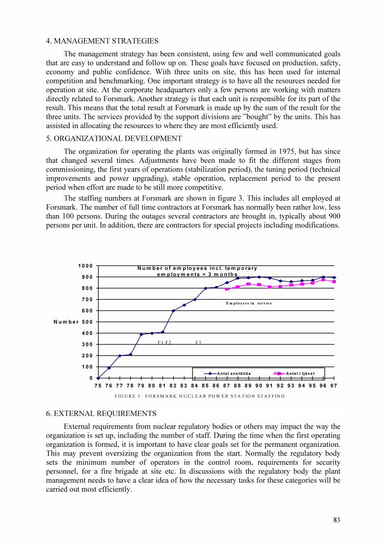
83
4. MANAGEMENT STRATEGIES
The management strategy has been consistent, using few and well communicated goals that are easy to understand and follow up on. These goals have focused on production, safety, economy and public confidence. With three units on site, this has been used for internal competition and benchmarking. One important strategy is to have all the resources needed for operation at site. At the corporate headquarters only a few persons are working with matters directly related to Forsmark. Another strategy is that each unit is responsible for its part of the result. This means that the total result at Forsmark is made up by the sum of the result for the three units. The services provided by the support divisions are ”bought” by the units. This has assisted in allocating the resources to where they are most efficiently used.
5. ORGANIZATIONAL DEVELOPMENT
The organization for operating the plants was originally formed in 1975, but has since that changed several times. Adjustments have been made to fit the different stages from commissioning, the first years of operations (stabilization period), the tuning period (technical improvements and power upgrading), stable operation, replacement period to the present period when effort are made to be still more competitive.
The staffing numbers at Forsmark are shown in figure 3. This includes all employed at Forsmark. The number of full time contractors at Forsmark has normally been rather low, less than 100 persons. During the outages several contractors are brought in, typically about 900 persons per unit. In addition, there are contractors for special projects including modifications.
N u m b e r o f e m p lo y e e s in c l. te m p o ra ry
e m p lo y m e n ts > 3 m o n th s
0
1 0 0
2 0 0
3 0 0
4 0 0
5 0 0
6 0 0
7 0 0
8 0 0
9 0 0
1 0 0 0
7 5 7 6 7 7 7 8 7 9 8 0 8 1 8 2 8 3 8 4 8 5 8 6 8 7 8 8 8 9 9 0 9 1 9 2 9 3 9 4 9 5 9 6 9 7
N u m b e r
A n ta l a n s tä lld a A n ta l i tjä n s t
E m p lo yees in serv ice
F IG U R E 3 : F O R S M A R K N U C L E A R P O W E R S T A T IO N S T A F F IN G
Y ear
F 1 F 2 F 3
6. EXTERNAL REQUIREMENTS
External requirements from nuclear regulatory bodies or others may impact the way the organization is set up, including the number of staff. During the time when the first operating organization is formed, it is important to have clear goals set for the permanent organization. This may prevent oversizing the organization from the start. Normally the regulatory body sets the minimum number of operators in the control room, requirements for security personnel, for a fire brigade at site etc. In discussions with the regulatory body the plant management needs to have a clear idea of how the necessary tasks for these categories will be carried out most efficiently.

84
At Forsmark there has been very few changes in external requirements directly affecting staffing. However, changes to rules and regulations regarding training and maintenance, e.g. inservice inspections, have created a need for more people in certain areas.
7. INTERNAL REQUIREMENTS
The management strategies should be formed early, with a look at the horizon. The internal requirements on the organization may vary over time, but a consistent strategy should be used. One trend we have seen in Forsmark is a change to have a greater need for people with higher education (university degree). With a proven maintenance program that is working well,less resources are needed for maintenance. However, aging equipment need replacement needs replacing, which means more resources are involved with modifications.
8. RECOMMENDATIONS
Be aware that the organization must be adjusted during the years of operation. During start up special needs for training and forming routines and procedures needs to be addressed. Later the organization should be able to handle modifications.
It is important to develop the right tools early for supporting the organization. This should include systems for configuration control and for maintenance work control.
With new plants the possibilities to use computers to monitor plant status and equipment condition should be used.
Plant staffing should be adequate to perform the needed tasks, but should not be too generously sized from the start. It is very hard to make a downsizing, while a shortage of people normally can be compensated by contractors until the plant staff has been employed and trained.

85
STAFFING AND TRAINING EXPERIENCE AT THE
BILIBINO NUCLEAR POWER PLANT
F. TUKHVETOV
WANO,
Moscow, Russian Federation
Abstract
Bilibino NPP has four 12 MW(e) water cooled graphite moderated channel reactors. The plant
has been in operation since 1973 in conditions of isolated local energy system in a remote area with
extreme climatic conditions. The plant accounts for almost 70 per cent of energy produced in the
region, it also provides heating to the regional centre. The plant's organisational structure is on the
whole consistent with the standard structure of other NPPs of ex-USSR. At the same time there are
some specific features due to high cost of personnel in the prime cost of the generated energy. As a
result a need arises to broaden the task of catering for each worker and, therefore, to extend and
increase the level of training. The number of high-quality personnel is on the increase. A method of
step-by-step training is widely used at all work areas for training operations personnel. At the end of
each step a worker is engaged in independent activities at this work area. When a plant is located in a
remote area efficient and effective maintenance becomes highly instrumental. The engineering and
design support on the part of the utility and equipment manufacturer begins to play a greater role.
Activities to optimise the plant organisational structure were mostly characterised by merging of
subdivisions and by some change in the proportion of different categories of personnel. It would be an
optimum decision to put all supporting services, namely, logistics, book-keeping and staffing
departments, within the utility's authority. Operations experience of the Bilibino plant will certainly
be valuable for projection, location choice and staffing of plants with small and medium reactors.
1. STAFFING AND TRAINING EXPERIENCE AT THE BILIBINO NUCLEAR POWER
PLANT
The Bilibino NPP operates the EGP=6 nuclear reactors, which are water-cooled
graphite-moderated heterogeneous channel type reactors. Their prototypes are two Beloyarsk
plant reactors and the world’s first reactor t Obninsk. The plant has four similar units and a set
of auxiliary plant equipment. The design electric power is 48 MW(e). Over the recent five
years the average plant load has been 15-25 MW(e), moreover maximal heat supply from
turbine extraction piping sometimes exceeds prescribed thermal power of 67 Gkal/h and has
been permanently kept at the same level. Construction of the site began in 1966. ON
December 31, 1973 start-up activities were completed at unit 2. In January 1974 the unit
generator was and connected to the grid and loaded. IN April, 1974 the unit was brought to
rated power. Unit 2, 3 and 4 were put into operation in late 1974, late 1975 and in 1976
respectively. At present the staff of the plant numbers 670 people.
The Bilibino nuclear power plant provides energy for the Chaun-Bilibino mining and
industrial region of Chukotka and heat to the nearby town of Bilibino. The plant operates in
the autonomous Chaun-Bibilibin energy system. It is connected to the grid by three
transmission lines, which are 1,000 kilometers long. The floating diesel electric station
“Northern Lights” operating at the design 24MW(e) power and Chaun thermal power station
(design electric power of 30.5 MW(e)) operate in the energy system along with the Bilibino
plant. Bilibino NPP has been operating in a load following mode that requires reactor
operation within a range of 50 to 100% of the rated power. It is explained by the fact that due
to its design the Bilibino plant is the most stable power source in a load following mode of
operation as compared to other stations in the energy system. This mode of operation is a

86
design-based one and does not require trip of equipment. The Chaun-Bilibino energy system
has an irregular 24 hour load schedule, which requires significant multiple power changes.
In 1974, the Bilibino NPP started to supply heat to an adjacent industrial complex. IN
1976 a heating system was commissioned to provide heat to living quarters of the town of
Bilibino and industrial enterprises. the Bilibino plant is the only source of thermal energy I the
region. Most of its thermal energy goes to communal services and caters for every day needs
of the population.
The construction of Bilibino NPP was of great importance to the region as it created a
powerful and reliable energy source, which does not involve a lot of tranportation. Instead of
transporting 190, 000-200, 000 tonnes of fossil fuel a year for electrical station and boiler-
house the Bilibino NPP takes delivery of fuel channels weighing a total of just 40 tonnes
(including the containers). Cargo is delivered by air.
Specifics of the Bilibino NPP location:
�� Severe climate (lasting winter temperature of up to -50 C) with a long polar night;
�� The region is water-short due to lack of ice-free streams, rivers and lakes;
�� Mountainous relief with a mixture of rocks and deep internal ice;
�� Remoteness from industrial regions and main roads, including ports of the northern
shipping route. Seasonal character of “enter” roads used for forwarding food and
equipment, fuel and construction materials for the region and the Bilibino NPP. Some
goods can redelivered by air, but such delivery is very costly and there are limitations by
weight and size.
�� Relatively small power of local energy system;
These specific features of the region predetermined special requirements for the NPP
and its equipment, in particular for the reactor. In general these requirements are as follows:
�� Simple and reliable design configuration and all its elements, minimum of equipment
requiring qualified operations and maintenance;
�� Great reactor stability n emergencies, including loss of power supply to house loads;
�� Development of equipment allowing for local transport means,, that is mostly in units to
ensure minimum of installation in-situ. Owing to this requirement the major equipment
location project so much needed by the plant was developed.
�� Use of plant water cooling systems or systems of heat removal from turbine condensers
with minimal water losses.
�� The above explains the following peculiarities of the Bilibino NPP operation:
�� NPP has four similar units;
�� All the units are located in the same building, moreover turbines and reactors are located
in the halls shared by all units;
�� Due to a large number of units and with maintenance lasting an average of 2-3 months,
maintenance activities are always underway at one or the other unit;
�� Extreme remoteness of the plant accounts for financial difficulties related to employment
of contract workers;
�� Long holidays for employees - six months after 1.5 years of work record (according to the
law on staffing in conditions of the Extreme North);
�� Location of Bilibino NPP in the region where energy is poorly developed makes it
impossible to hire qualified personnel among local population;
�� The region lacks infrastructure for training personnel for NPPs, including workers.
87
All these peculiarities result in the following:
�� Personnel is very large I number per installed capacity (15 times higher than at other
Russian NPPs);
��Labour payment funds account for a significant share of electric energy cost (an average of
40% a year);
��Large number of maintenance personnel (it is very costly to involve contract workers);
��Training of practically all the personnel (both operations and maintenance personnel) is
conducted directly at their work areas;
��Experienced personnel from other NPPs cannot be involved owing to the unique design
configuration and equipment.
How do all these things influence staffing and training of personnel?
(1) All operations personnel are trained directly at their work areas. Moreover, only
consecutive promotion is possible. For example, in reactor-turbine department it is as
follows:
— Fitter on duty
— Reactor department operator
— Turbine department field operator
— Senior turbine department field operator
— Unit operator
— Senior unit operator
— Reactor-turbine department shift supervisor.
Thus, senior operations personnel have practical experience of operating all the
equipment.
(2) Maintenance activities have a greater scope.
— Each subdivision caters for all the units,
— Much more equipment is serviced than at other NPPs.
(3) There are more specialists of higher qualification at the plant.
(4) There has been a merger of a number of subdivisions:
— Reactor turbine department operates all operating equipment.

.

89
STAFFING REQUIREMENTS FOR FUTURE SMALL AND MEDIUM
REACTORS BASED ON PROJECTIONS IN THE RUSSIAN FEDERATION
G.M. ANTONOVSKY, N.G. KODOCHIGOV,
A.V. KURACHENKOV, V.V. NOVIKOV
EDBME,
Russian Federation
Abstract
Experimental Design Bureau of Mechanical Engineering (OKBM) specializes in the
development of small and medium power reactors having different purposes. They include reactor
plants for NPHPP, nuclear district heating power plants and propulsion plants. Small and medium
power plants have simpler processes of electricity and heat production, less systems, simpler control
algorithms and considerably enhanced inherent safety properties. These plants are mainly equipped
with passive safety systems. These properties are especially characteristic for reactor plants of nuclear
district heating power plants and HTG reactor plants. The designs of small and medium power plants
actually provide a high degree of control automation which considerably reduces workload on the
personnel in both normal and abnormal operation conditions. All this allows the reduction in
personnel for small and medium power reactors if compared to high capacity reactor plants. But due
to objective reasons the specific number of personnel (man/MW) for average and especially small
capacity reactors considerably exceeds the value for high capacity reactor plants. At the same time
one can propose a set of organization — technical measures allowing the increase in this value in
future. Safety requirements imposed for small and average capacity reactors are the same or more
strict than those for high capacity reactors. That’s why the requirements to the training of personnel
for such reactor plants are not allowed to be lowered if compared to the requirements imposed to the
personnel of high capacity reactors.
1. INTRODUCTION
Small and medium power nuclear plants of various purposes are being now developed in
Russia and abroad. They include NPHPP, nuclear district heating power plants.
The main potential customers of these plants are developing countries, regions with
non-developed energy infrastructure, for example, due to hard climate, etc.
Technical and economic peculiarities of power plants with average and, especially,
small capacity reactors are reflected on various aspects of their operation including the
requirements to the personnel.
The present report contains certain results of the analysis dedicated to the influence of
nuclear power plants with small and medium power reactors on the personnel with account of
previewed design solutions and accumulated operation experience.
Average and small capacity NPPs being developed by OKBM.
OKBM belongs to Russian leading design bureaus developing nuclear power plants.
The development of nuclear propulsion power plants is one of the OKBM's main
specialization’s. These plants include practically all submarine and navy ship power plants
and all nuclear power plants for the civil fleet.
OKBM also developed a set of reactor plant designs for small and average capacity
energy and heat co-production power plants and district heating power plants.

90
The most famous designs of small and average capacity reactors include:
�� reactor plants of ABV type;
�� reactor plants of KLT type;
�� reactor plants of ATETs type;
�� reactor plant VPBER-600;
�� reactor plant AST-500;
�� reactor plant with gaseous coolant (VGM, GT-MHR).
The main performances of these power units with the specified reactor plants are given
in Table 1.
Table 1. Main performances of nuclear power plant power units developed by OKBM
Parameter VPBE
R-600
ATETs KLT ABV AST
-500
VGM GT-
MHR
Thermal power, MWt 1800 690 150 54 500 200 600
Electric power, MWe 640 230 35 12 77 285
Quantity of heat produced,
GKal
1050 170 25 24 430
It should be noted that reactor plants except the reactor plant AST-500 developed
specially for district heating power plants represent multipurpose power sources which can be
used for electricity, heat, desalinated water production, etc.
The market of small and average capacity reactors exists and is supposed to exist for a
long time. That's why the associated problems remain actual and there is time to solve them.
What's the principal difference between small and medium power reactor plants and
high capacity ones.
Small and medium power plants have simpler processes of electricity and heat
production and relatively smaller number of systems. Together with a simple reduction in
number of auxiliary equipment and systems because of lower power, small and medium
power reactor plants have simpler steam production procedure, as a rule, with the use of one
through steam generators. Often these plants are equipped with integral or unit reactors, and
this fact considerably simplifies the primary circuit by due to the absence of main circulation
pipelines. The heat production procedure is considerably simplified for AST-type plants. Only
water circuits are used. The usage of direct gas-turbine cycle is adopted for gas cooled reactor
plants and the thermal energy is converted into electricity in the primary circuit.
Small and medium power plants are characterized by considerably enhanced inherent
safety properties: the level of natural circulation is higher, reactors with natural primary
circulation are very frequently used for the plants, the specific volumes of primary coolant are
higher, the primary circuit has enhanced accumulative capacity, etc.
These plants are mainly equipped with passive safety systems. These solutions are
especially characteristic for district heating power plants and HTGR.
Small and average capacity plants have simpler control algorithms.

91
All the abovementioned leads to the fact that the solution of control automation
problems associated with average and, especially, small capacity reactor plants is simpler
provided the control system cost is minimal.
Higher level of small and average capacity reactor plants control automation
considerably reduces the workload on the operation personnel in both normal and abnormal
operation conditions and has a favorable effect on the reduction in power plant operation
personnel.
Number of personnel for small and average capacity nuclear power plants
The analysis of personnel number at power plants of various capacity shows two main
problems:
� reduction in total NPP personnel number in case of power reduction;
� increase in specific personnel number (man/MW) for medium and, especially, small power
reactors.
Specified dependencies of industrial-production personnel number and industrial-
production personnel specific number from power are given in Table 2.
Table 2. Operation personnel number and operation personnel specific number of domestic
power plants
NP-
1100
AES-91 AES-92 NP-500 VPBER-
600
GT-
MHR
ABV-6
Power, MW(e) 1150 1074 1068 645 640 285 12
Personnel, men 325 349 320 303 273 230 103
Specific number,
man/MW(e) 0.283 0.325 0.3 0.47 0.428 0.8 8.5
The reduction in overall NPP personnel in case of power reduction can be explained by
a set of reasons, i.e.:
�� reduction in the quantity of equipment associated with power reduction and reduction in
the quantity of service and auxiliary systems;
�� simplification of technological systems and equipment in case of reduction in its unit
power;
�� automation of monitoring and control, introduction of diagnostic systems.
The reduction in the main component of the total NPP personnel number - industrial-
production one - is considerably smaller than that in NPP power. It is shown in Tables 3 and 4
containing the data on the number and structure of small and average capacity NPP personnel.
Table 3. Number of personnel for a small capacity ABV — type NPP with electric power
12 MW(e)
Title Value
Administrative 2
Repair 36
Operation 103
Total 141

92
Table 4. Number of personnel for the existing Westinghouse NPP and for the design of AP-
600 NPP with electric power 600 MW(e)
Department An existing
Westinghouse 2-
loop
AP-600
Administration 34 35
Operations / engineering 70 77
Maintenance 82 56
Planning 4 13
HP / chemistry 38 35
Training 25 35
Contractors (including security) 85 85
Total 338 336
Operation personnel amounts to 190 and 168 respectively.
Specific number is 0.317 and 0.28 man/MW
The analysis of the specified data shows that the number of the operation personnel for
a NPP equipped with small and average capacity reactors deviates not more than by 3 times,
the power being reduced from the maximum to the minimum — from 600 MW(e) to 12
MW(e).
That’s why the specific number of the personnel (man/MW) considerably increases if
the power of a NPP is reduced.
This factor is considerably higher for average and, especially, small capacity reactors
than for high capacity ones (see Table 2).
The number of NPP personnel is defined basing upon the regulations in force and
design documentation requirements for the equipment being used at a specified power unit.
So, there are two possibilities to control this factor.
From one hand, this is the upgrading of regulations. It should be noted that regulations
concerning the number of personnel are possible to be revised only basing upon operation
experience. In this case the policy of utilities aiming at the reduction of operated NPPs costs
should be the governing factor.
At present, the number of Russian NPPs personnel is being optimized. The fact that
repair personnel is no longer included in the NPP personnel made the number of personnel for
new designs of domestic NPPs closer to that of foreign NPPs equal in power.
From the other hand, the equipment being designed by design institutions for future
NPPs requires minimal operation maintenance without reduction in its reliability; the control
system automation level is increased, diagnostic systems are introduced, etc.
Reactor plants of Russian nuclear-powered ships can be cited as an example of
positive results achieved. At the same time it should be noted that high compactness and
minimal maintenance of reactor plant equipment in some cases lead to a hindered access to

93
the equipment or to the impossibility to maintain individual elements of reactor plants in
course of operation. That’s why these elements are imposed to higher reliability requirements.
The positive operation experience of ship reactors shows that the decision is right.
The experience of Navy reactor plants development and operation also shows that the
number of personnel for small capacity reactor plants can be considerably reduced.
The number and structure of personnel for Navy reactor plants were defined basing
upon the reactor plant reliability and safety analysis in a wide mode range.
The lowest operation personnel number was achieved for the reactor plant OK-550.
The number of personnel for this reactor plant was 7 persons.
Even as adjusted for the longer continuous operation characteristic for NPPs and for
the necessity to replace personnel in case of illness, vacation, retraining, etc., the number of
personnel will not exceed 12 persons.
Specific personnel number for this reactor plant with turbine power 29.4 MW was
0.238 man/MW. This value exceeded that for up to date high capacity NPPs.
The total number of personnel with account of high degree of automation amounted to
31 person.
The implementation of modular principle in course of NPP creation is one of ways to
reduce the number of personnel for NPPs equipped with small and medium power reactors.
This principle previews the usage of several reactor modules with common auxiliary and
service systems. The realization of such principle allows the reduction in the specific number
of NPP personnel up to the level comparable to factors of NPPs equipped with high capacity
reactors. Table 5 shows as an example the design number of personnel for the GA design of
GT-MHR NPP with one and four reactor modules.
Table 5. Number of personnel for the GA design of GT-MHR NPP with one and four reactor
modules
Department GT-MGR one
reactor module
GT-MGR four
reactor modules
Number of reactors 1 4
Electric power, MW(e) 262 1050
Number of personnel, men 166 241
Specific number of personnel, man/MW 0.63 0.23
Training of personnel for small and average capacity NPPs
Safety requirements imposed to small and average capacity reactors are the same or
more strict than those imposed to high capacity reactors.
As a rule, it is explained by the location of small and average capacity NPPs in the
vicinity of settlements. This fact does not permit to weaken the requirements to the training of
personnel for such plant if compared to high capacity reactors.
The requirements to the training of personnel for NPPs remain the same no matter the
power is:

94
�� special education is necessary;
�� knowledge and understanding of processes taking place in the reactor and the main
equipment of NPP;
�� training at the simulators.
2. CONCLUSION
At present, the number of personnel is one of the factors influencing the performances of
average and, especially, small capacity NPPs.
The specific number of personnel (man/MW) for small and average capacity reactors
is considerably higher than that for high capacity reactor plants.
The OKBM’s experience in development of small and average capacity reactor plants
shows that this problem can be solved by means of operation and combined efforts of
designers.
Main ways to solve this problem:
�� creation of reactor plant equipment for small capacity NPPs requiring less maintenance if
compared to high capacity NPP equipment;
�� enforcement of NPP systems and equipment control automation;
�� involvement of other institutions for periodic maintenance and repair;
�� account of modular principle in course of NPP designing;
�� modernization of regulations specifying the number and structure of small and average
capacity NPPs personnel with account of accumulated design and operation experience as
well as of peculiarities proper to this kind of reactors.
REFERENCES
[1] “Turning the key” Howard Brush, Theodore Andersen, Nuclear engineering, November,
1991.
[2] “Malaja skorostnaja avtomatizirovannaja podvodnaja lodka-istrebitel projekta 705
(705K)”. R.A.Shmakov, Vojenno-tekhnicheskij al’manakh “Tajfun”, 3/1997 (vypusk
#5).

95
MANNING DESIGNS FOR NUCLEAR DISTRICT-HEATING PLANT (NDHP)
WITH RUTA-TYPE REACTOR
V.S. GERASIMOVA, V.I. MIKHAN, À.A. ROMENKOV RDIPE, Moscow, Russian Federation
Abstract
RUTA-type reactor is a water cooled water-moderated pool-type reactor with an atmospheric
pressure air medium. The reactor has been designed for heating and hot water supply. Nuclear district
heating plant (NDHP) with RUTA-type reactor facility has been designed with a three circuit layout.
Primary circuit components are arranged integrally in the reactor vessel. Natural coolant circulation
mode is used in the primary circuit. A peculiarity of RUTA-based NDHP as engineered system is a
smooth nature of its running, slow variation of the parameters at transients. Necessary automation
with application of computer equipment will be provided for control and monitoring of heat
production process at NDHP. Under developing RUTA-based NDHP it is foreseen that operating staff
performs control and monitoring of heat generation process and heat output to consumers as well as
current maintenance of NDHP components. All other works associated with NDHP operation should
be fulfilled by extraneous personnel. In so doing the participation of operating staff is possible also.
1. INTRODUCTION
Pool type reactor is one of the promising low power reactors for future application with the purpose of heating and hot water supply, salt water desalination, air conditioning and other any possible demands. Similar developments had been performed in different countries [1, 2] including Russia [3, 4]. The studies on RUTA reactor (RUTA in Russian abbreviation —
reactor facility for heat supply under atmospheric pressure) are implemented in Russia.
2. RUTA REACTOR FACILITY
RUTA reactor is water moderated, water cooled pool type reactor with air medium under atmospheric pressure in above-water volume of the reactor. RUTA reactor-based plants with thermal power of 10, 20, 30, 55 MW had been considered with different depth of elaboration. The variant of reactor facility layout is presented in Fig.1.
RUTA reactor is arranged in a concrete vessel. The vessel has internal metal lining. Metal lining is made of bimetallic sheet while internal layer being of corrosion-resistant steel and external layer of carbon steel. Concrete vessel is a radiation shield also. The dimensions of vessel upper part are governed by sizes of the components placed in it, the dimensions of vessel lower part are due to the core dimensions and necessity to reduce the irradiation of vessel lining metal and concrete for ensuring their workability during required reactor service life.
The vessels of this type are employed with advantage over many years at a variety of pool type research reactors.
Draft section serving to arrange water downflow and upflow upstream and downstream of the reactor core, respectively, is installed in the lower part of the reactor.

96

97
The enclosure with a support plate is mounted inside the draft section at level of the core. Support plate serves to install the fuel assemblies and the displacers, nozzles of which are inserted into the plate holes; the enclosure is intended to shape external boundary of the core, at the same time the enclosure is a component of core vessel protection against core radiation. With this purpose the vertical channels filled with water are envisaged in the enclosure, and owing to this the necessary iron to water ratio to provide radiation shielding is ensured.
A shell of the draft section in its upper part passes smoothly to the upper distributing chamber. Upper distributing chamber is closed at the top by the cover to prevent mixing of coolant upflow with upper water volume. Thermal insulation is envisaged in the cover to make heat overflow to the upper water volume as low as possible. Control rod drives of the reactor and the elements for controlling its operation are mounted at this cover.
The pipelines, to which the feeding chambers of primary heat exchangers and then primary heat exchangers themselves are connected, branch off the distributing chamber. Plate-type heat exchangers are used as the primary heat exchangers.
Distributing and collecting manifolds connected with the primary heat exchangers by feeding and removing pipes are installed in the upper part of the reactor for coolant supply and removal.
Protective plates are placed above the reactor at the top to prevent the damages reactor internals as a result of external effects. The conjunctions between the protective plates are sealed to keep the reactor hall clear of the ingress of gas and steam from the reactor upper part.
3. NUCLEAR DISTRICT HEATING PLANT (NDHP) BASED ON RUTA REACTOR FACILITY
NDHP based on RUTA reactor facility has three heat transfer circuits. Heat transfer from primary circuit to secondary one and from secondary circuit to tertiary one is performed through heat exchange surfaces. Design coolant pressure in the secondary circuit is higher than in the primary circuit and design coolant pressure in the tertiary circuit is higher than in the secondary circuit for keeping the network water (coolant of tertiary circuit) free from possible contamination in the case of heat exchange surface tightness loss. Fuel assembly is composed of fuel rods with two zirconium claddings and silumin is filled between them for improvement of reactor facility reliability.
Primary circuit is formed inside the reactor water space by the system of reactor internals and consists of the core, draft section, primary heat exchangers, reactor pool, downcomer. Primary circuit is intended for heat removal from the reactor core and its transfer to the secondary (intermediate) circuit in the primary heat exchangers.
Natural circulation of the coolant with the possibility to increase power due to forced circulation when pumps are installed, has been envisaged in the primary circuit of RUTA reactor.
Secondary circuit is an intermediate circuit and is intended for heat transfer from primary to tertiary (network) circuit. Secondary circuit is used for reactor cooldown (at normal and emergency conditions) also. Secondary circuit consists of two independent circulation loops. Each loop represents the pressurized closed system involving primary and network heat exchangers, circulation pumps, pressurizer, riser and downcomer pipelines.

98
Coolant circulation in secondary circuit is performed by circulation pumps, natural circulation mode is possible under cooldown. The secondary coolant heated in the primary heat exchangers passes through pipelines to network heat exchangers and transfers heat to network water, then it is fed by circulation pumps to inlet of primary heat exchangers.
Tertiary circuit (network circuit) is intended for heat transfer to a consumer. Main equipment of tertiary circuit related to the reactor facility — network heat exchangers, pumps and valves — is located within the NDHP boundaries.
If NDHP consists of several power units, tertiary circuit is shared by all these power units.
4. INTEGRATION OF NDHP WITH RUTA REACTOR FACILITIES INTO HEAT SUPPLY SYSTEMS
When pool type reactors are used as a part of NDHP, to attain water temperature above 85...88°Ñ in the network circuit is impossible without additional devices. Such network water temperature is quite sufficient for small inhabited localities and consumers located near the heat supply sources. At the same time RUTA-based NDHP may be used (integrated) in currently available district heating systems with higher initial temperature of direct network water. In these cases NDHP should be used along with available heat-electric generation plant (HEGP) (or boiler plant).
Schematic diagram of RUTA-based NDHP application in combination with HEGP is presented in Fig.2. HEGP is connected to NDHP network circuit in series. The coolant of network circuit is heated in the network heat exchangers and then enters HEGP where it is heated up to the required temperature.
On the basis of the studies performed it is established that NDHP optimum power in district heating system is 30–40 % of system maximum power. Required temperature of direct water has different values depending on outdoor temperature, the demands for required thermal load vary. Under combined application the RUTA reactor facility operates at steady-state mode for much of the lifetime, and it is the concern of HEGP to follow the changes in demands for thermal load of heating system and to carry peak thermal loads.
5. MAINTENANCE AND REPAIR
RUTA-based NDHP is designed for prolonged lifetime during a period of several decades. The lifetime is limited mainly by the serviceability of reactor vessel (tank) and is refined with necessary grounds under developing a detailed design of the reactor.
Operation of main equipment, pipelines, valves and cables is designed for prolonged period also, ranging up to NDHP design lifetime conformably to certain components. If to keep the serviceability of separate components during such the period is impossible, their replacement will be required once or twice over the period of NDHP operation.
Such is the case for the actuators of the control and protection system, involving control members and drives for their movement in the reactor, and for monitoring sensors.
Conformably to the equipment, valves and certain other NDHP components the replacement of separate units will be necessary.
The terms on complete or partial replacement of all NDHP components should be specified in the NDHP design. Therewith such replacement with minimum labor input and

99
radiation burden should be envisaged in their structure, and technology and work organization of such replacement should be elaborated.
Taking into consideration the fact that the replacement of NDHP components or their separate units will be carried out rather rarely, this work, being preventive overhaul in essence, should be performed not by NDHP operating staff, but by extraneous personnel drawn into this work specially.
Apart from replacement of NDHP components and their separate units, periodic and current maintenance of these components will be demanded. Periodic maintenance or running repair will be necessary once in several years. Running repair as well as preventive overhaul is allowed to be fulfilled by extraneous personnel drawn into these works specially.
Current maintenance, which should be minimized in the design, will be carried out by duty operating staff.
Apart from the works above specified, the necessity for removal of radioactive waste will arise periodically at NDHP. In the course of operation the waste should be collected by the duty operating staff in temporary storage facilities at the plant site and then disposed by extraneous personnel beyond the NDHP.
As for refuelling, partial refuelling of one-third of the core, is provided with three-year interval. The refuelling will be carried out by the extraneous personnel also.
Such an approach can be realized by different ways.
If several NDHPs will be built close to each other, it is appropriate to have common regional center for their maintenance with necessary complete set of the equipment and production accessories to carry out the works indicated above. The personnel required for their fulfillment will be concentrated in this center.
It is possible to use nearby NPP or other nuclear center having the opportunities to perform the works indicated for servicing one or several NDHP.
The problem becomes more intricate if need be to construct single NDHP remote from the centers available. In this case it is necessary to draw the personnel and technological opportunities from distant objects; this, of course, leads to increase in cost of produced heat.
6. PRODUCTION PROCESS CONTROL AND MONITORING
NDHP operation may be broken down arbitrarily to two parts. The process of heat production, in the course of which the reactor operates at different power levels and coolant circulates in intermediate and network circuits due to pumps operation, is one of them.
Other part involves the maintenance of NDHP equipment and other components by means of proper repairs, removal of radioactive waste from NDHP, refuelling and disposal of spent fuel and certain other operations, needed for the plant functioning.
The former part of plant operation (process of heat production) is performed by NDHP operating staff, the latter part — by extraneous personnel.
Under normal operating conditions the principal control problem is to ensure their stability. In so doing staff activities are reduced to monitoring of the parameters and infrequent control actions.

100

101
Under heat production process the problems needed to be solved are keeping and changing in reactor power within the required limits and carrying out water circulation in intermediate and network circuits and also auxiliary systems and equipment running. To accomplish these tasks it is necessary to execute the movement and retention of control members (absorber rods), pumps turn-on and turn-out, valves changeover and other operations for equipment control.
Therewith it is necessary to execute monitoring of the parameters of production process.
Primarily, the parameters to be monitored are the characteristics of fission process as to neutron flux and reactivity. Coolant temperature at the core outlet and at a number of other points in all three circuits of heating system, coolant pressure and flowrate in the circuits, level in the pressurizer, radioactivity of working fluids and certain other parameters are monitored also.
A number of parameters to be controlled doesn’t exceed two—three dozens; that is rather few in comparison with other types of NPP. Therewith the most of these parameters will be needed solely for obtaining the information on the process quality, and only several parameters will be necessary for its running.
Automation system will measure continuously the parameters governing the course of heat production and keep it within the limits of predetermined parameters. The system will change the process parameters as a whole according to operator request. It will also record the process running for subsequent analysis, if necessary.
Thus, a task for the staff executing the production process reduces to giving its parameters and watching over its course.
In the cases of the process parameters overshooting the automation system should respond itself in a proper manner and correct the process course or, if required, stop it. Several channels and component redundancy will be provided for attaining the required reliability of the system.
Non-operating part of RUTA-based NDHP running, as mentioned above, should be executed by extraneous personnel. During this work, recording its performances such as fuel consumption, amount of radioactive waste, labour input, radiation burdens and so on will be implemented by the personnel, executing this work, in NDHP automation system and also in automation systems of the appropriate centers.
7. NDHP STAFF
Taking into consideration a simplicity of reactor design and NDHP flow diagram and also high safety of NDHP with ultimate self-security against accidents, the limited number of operating staff will be needed for executing the heat production process. Suggested data on the staff number are given in Table 1.
The staff number may be reduced as the operation experience being accumulated and the automation system being developed.
The scope of the works executed by the extraneous personnel estimated by experts as 1000 man-days per year on the average.

102
Table 1. Number Of Staff
Name of departments
and established posts
Category of
employees
Number of
shifts
Number of
employees,
persons
Number of
employees
per the
greatest shift,
persons
Office and management personnel
Station Management
1. Chief Manager specialist 1 1 1
2. Chief Engineer specialist 1 1 1
3. Production and Engineering Group specialist 1 1 1
4. Economist, accountant specialist 1 1 1
Total on Station Management 4 4
Production personnel
Reactor Department
1. Senior engineer on the unit control specialist 4 5 1
2. Duty metalworker worker 4 5 1
Total on Reactor Department 10 2
Chemical and Technological
Department
1. Technician on all systems specialist 4 5 1
Total on Chemical and Technological Department 5 1
Automation Department
1. Engineer on automation system specialist 1 2 2
2. Duty metalworker worker 4 5 1
Total on Automation Department 7 3
Administrative and General Service
Area
1. Room sweeper worker 1 2 2
Total on Administrative and General Service Department 2 2
Total on the station 28 12
REFERENCES
[1] Cuttler, J.M., 1991. Design of SES-10 Nuclear Reactor for District Heating, Report of Atomic Energy Canada Limited, AECL-10222, 1991.
[2] Vecsey, G., Doroszlai, P.G.K., 1988. GEYSER, a simple, new heating reactor of high inherent safety, Nuclear Engineering and Design 109, pp. 141–145.
[3] Adamov, E.O. et al., 1996. A new impulse in the development of nuclear pool-type reactors for underground heating plant: designing, running background and possible perspectives. Proc. ICONE-4, Vol. 2, pp. 271–280.
[4] Adamov, E.O., Cherkashov, Yu.M., Romenkov, A.A., Mikhan, V.I., Semenikhin, V.I., 1997. Inherently safe pool-type reactor as a generator of low grade heat for district heating, air conditioning and salt water desalination, Nuclear Engineering and Design 173, pp. 167–174.
103
IMPROVEMENTS IN NUCLEAR PLANT STAFFING RESULTING
FROM THE AP600 DESIGN PROGRAMME
C. MYCOFF
Westinghouse Electric Co.,
Pittsburgh, Pennsylvania, United States of America
Abstract
The staffing for a single-unit, AP600 is estimated to require a staff for operation and
maintenance about 32% smaller than current generation power plants of similar size. These staffing
reductions are driven primarily by various features incorporated into the AP600 plant design.
1. INTRODUCTION
The Westinghouse AP600 reactor has been designed as part of the advanced light water
reactor (ALWR) programme sponsored by the U.S. DOE, EPRI and U.S. and international
utilities. Following an extensive design review, the AP600 received final design approval on
September 3, 1998 from the U.S. NRC. A detailed design programme (FOAKE-First of a kind
engineering) has been completed under the sponsorship of DOE, the Advanced Reactor
Corporation (ARC), and EPRI.
Electric Power Research Institute (EPRI) has, with a broad participation of numerous
countries, developed a utility requirements document (URD) for ALWRs, taking into account
the wealth of information related to nuclear power plant safety and operations that has been
generated worldwide with commercial nuclear power. The purpose of the URD is to delineate
utility desires for their next generation of nuclear plants, and to this end, it consists of a
comprehensive set of design requirements for future plants.
Incorporation of the URD has been a design goal for the AP600 from the design
inception, and has continued to be so during the FOAKE programme. The AP600 has a well-
defined design basis that is confirmed through proven systems and equipment, engineering
analyses and testing and is in conformance with the URD.
The AP600 FOAKE programme has had extensive utility involvement in the detailed
design process. It included participation of 16 utilities in the U.S. Experts from these utilities
were located on-site at Westinghouse (20 man–a) in the ARC project office and provided
oversight for the detailed engineering. Approximately 20 formal utility steering group
meetings and bi-monthly ARC utility sponsor group meetings were held to review detailed
aspects for the design. In addition, monthly project meetings were held, and in-depth task
teams were created for significant or key issues including maintainability guidelines and
allocation, refuelling outage plan, valve standardization guidelines, maintenance isolation
valve design criteria, and constructability plan. A detailed review of the AP50 in-service
testing (IST) plan was conducted by the utilities, and detailed procedures and scenarios were
analysed to verify that the proposed IST could be conducted with the plant as designed.
Another area of significant utility involvement was in the area of plant layout focusing
on such features as containment access, laydown space, special platforms for improved
maintenance inside containment, other repair and maintenance provisions using cranes and
lifting devices, and use of standard service modules throughout the plant. With the use of the
AP600 3D model, utility personnel have been able to perform simulated walkdowns of the
plant to improve potential maintenance problems.

104
As part of the FOAKE programme, the utilities provided detailed review, comment and
approval of AP600 deliverables including:
�� system specification documents;
�� piping and instrumentation diagrams;
�� general arrangement drawings;
�� plant 3D model;
�� pipe routing drawings;
�� control logic diagrams;
�� one-line diagrams;
�� concrete outline/structural steel drawings.
2. AP600 DESIGN FEATURES
Simplification
The AP600 uses passive safety systems to enhance the safety of the plant and to satisfy
NRC safety criteria. These passive safety systems result in increased safety and also
significantly simplify pant systems, equipment, and operation. The systems use only natural
forces, such as gravity, natural circulation, and compressed gas. No pumps, fans, diesels,
chillers, or other rotating machinery are used for supporting safe shutdown of the plant. A few
simple valves are used to align the passive safety systems when they are automatically
actuated. The passive safety systems are significantly simpler than typical PWR safety
systems. Simplified safety systems reduce surveillance requirements by enabling significantly
simplified technical specifications.
In addition to being simpler, the passive safety systems do not require the large network
of safety support systems needed in typical nuclear plants, such as AC power, HVAC, and
cooling water systems and seismic buildings to house their network of support systems (e.g.
air start, fuel storage tanks and transfer pumps, and the air intake/exhausted system). As a
result, the fuel storage tanks and transferpumps, and the air intake/exhaust system). As a
result, the support systems no longer need to be safety grade and can be simplified or
eliminated. Elimination of technical specifications from those systems remaining simplifies
maintenance.
The simplifications in the AP600 dramatically reduce the amount of equipment to be
maintained and inspected while improving plant operability. These equipment reductions, as
indicated in Table 1, result in direct reductions in required inspection and maintenance
activities.
Table 1. AP600 Equipment, Component and Building Reductions
(compared to a conventional, 2-loop 600MWe plant)
Category Reduction
Valves 50%
Pumps 35%
Safety class pipe 80%
Seismic building volume 45%
Cable 70%
Other aspects of the design also contribute to direct reductions in required inspection
and maintenance activities. The cold leg lines of the reactor coolants loops are forged and then

105
bent by a hot induction forming process. The use of a pipe bend reduces in-service inspection
requirements by eliminating welds. The steam generator channel head is a one-piece forging
with manufacturing and inspection advantages over multi-piece, welded components.
Use of canned motor reactor coolant pumps allows elimination of RCP seal injection
and leakoff pipe and valves. Since the pumps have no seals, they cannot cause a seal failure
LOCA and seal replacement activities are eliminated.
Use of reduced-worth control rods to achieve load follow without requiring changes in
soluble boron concentration allows elimination of the boron recycle system and the rector
makeup water system. Liquid radwaste is simplified by the use of modern resin types —
processes, thereby eliminating a large, complicated and troublesome evaporator. Gas radwaste
is simplified by use of charcoal bed and has no compressors or storage tanks. Solid radwaste
is greatly simplified by use of portable de-watering equipment instead of onsite solidification
equipment.
Standardization
Early design work intentionally provided for the selection of equipment such as pumps,
valves, and motors, and commodities such as pipe, cable and structural steel, on a consistent
and standard basis throughout the plant to minimise spare parts inventory, training costs,
maintenance procedures, and human error in servicing multiple similar components, for
example, standardisation of air handling units (AHU) has reduced the number of unique
designs from 44 to 16. Within each AHU design, standization is being applied to unit layout,
component standardization, and electrical interface connections. As a major activity in valve
standardization, 24 standard valves account for over 60 percent of non-packaged valves.
Plant layout
Plant layout ensures adequate access for inspection and maintenance. Laydown space for
staging of equipment and personnel, equipment removal paths, and space to accommodate
remotely operated service equipment and mobile units have been considered as part of the
plant design.
As an example, accessibility to the containment during an outage is extremely important
to those maintenance activities that can be performed only during to the outage. A
conventional containment may have only one large equipment hatch, a personnel airlock, and
an emergency escape hatch. The AP600 containment contains a 22-foot (6.7m) diameter main
equipment hatch and personnel airlock at the operating deck level, and a 16-foot (4.9 m)
diameter maintenance hatch with truck access and personnel airlock at grade level. These
large hatches significantly enhance accessibility to the containment during outages and,
consequently, reduce the potential for congestion at the containment entrances. These
containment hatches, located at two different levels, allow activities occurring about the
operating deck to be unaffected by activities occurring below. The containment arrangement
also provides significantly larger laydown areas inside containment than most conventional
plants at both the operating deck level and maintenance floor level. Additionally, the auxiliary
building and the adjacent annex building provide large staging and laydown areas immediately
outside of both large equipment hatches.
Accessibility to equipment and components is also enhanced by aspects of the plant
design. The reactor coolant pumps mount directly on the channel head of each steam
generator. This allows the pumps and steam generator to use the same structural support,
greatly simpfliying the support system and providing more space for pump and steam

106
generator maintenance. The reactor coolant loop configuration and material selection yield
sufficiently low pipe stresses so that the primary loop configuration and material selection
yield sufficiently low pipe stresses so that the primarily loop and most of the high energy
auxiliary lines larger than 4th
are qualified to demonstrate leak-before-break. Thus, pipe
rupture restraints are not required, greatly simplifying the design and providing enhanced
access for maintenance. The simplified RCS loop configuration also allows for a significant
reduction in the number of snubbers, whip restraints, and supports.
Access platforms and lifting devices are provided at equipment locations requiring
periodic inspections, testing, or maintenance. Standard plant services such as electrical power,
demineralized water, breathing and service air,, ventilation and lighting are provided in all
buildings at strategic locations to facilitate maintenance activities.
Instrumentation and control
The AP600 instrumentation and control has been designed as an integrated system with
consistent and efficient interfaces, improved availability and operability, reduced spare parts
requirements, and considerable design flexibility. The I&C design includes equipment for
control tasks in both the nuclear and turbine islands, thereby extending plant I&C uniformity
and further reducing spare parts requirements.
The I&C system also contains a number of features resulting in improved maintenance.
More accurate and stable calibrations result from entering setpoints in engineering units. A
printout of these data may be requested for verification. No scaling manuals are required, and
because values are stored in digital memory, they do not drift. Semi-automatic test subsytems
are implemented in the equipment design. This feature allows maintenance personnel to
perform periodic functional checks in an efficient manner. Since testing time is reduced, both
plant safety and availability are improved. Improved failure diagnosis allows troubleshooting
down the circuit card or input — output module, reducing repair time for a given fault.
Availability is improved because when one protection channel is undergoing maintenance or
test, two out of four logic will automatically change to two out of three when a channel is
bypassed. Modular design of the protection and safety monitoring system electronics aids in
identifying and repairing equipment failures.
Human systems interface
The design process for the AP600 main control room (MCR) and human system
interface (HIS) follows a human factors engineering programme reviewed and approved by
the U.S. NRC. A model of human decision making is mapped to the HSE resources (the alarm
system, plant information system displays, computerised procedures, control, qualified data
processing system, wall panel information systems, and controls). The design features of the
HIS resources support the aspects of the human decision making model. A detailed operating
experience review has been conducted and the design of the HIS addresses human
performance issues identified by the review. Execution and completion of this design process
shall result in an HIS design that manages the presentation of plant information in a much
more effective manner that the control rooms of currently operating plants. Operations,
testing, and maintenance are simplified. Due to features of the advance I&C systems, the
number of plant transients caused by sensor failures shall be drastically reduced. Accident
monitoring and safety parameters are displayed on safety qualified displays with a co-
ordinated set of graphics generated by the qualified data processor. The major benefits of the
improved MCR and HIS are:

107
�� Presentation of alarms is effectively managed to avoid “alarm avalanche”.
�� Presentation of plant information and controls is organized in such a way as to enhance
human decision making.
�� Computerised emergency operating procedures reduces the operator’s mental workload
during high stress situations.
�� Wall panel information system (wall mounted large screen displays) provides a common
frame of reference tot he MCR operating crew and helps maintain overall plant situation
awareness.
�� Reduction in MCR hardware cost due to the compact workstation (soft control and
monitoring) design.
Plant staffing study methodology
A joint utility — vendor analysis of staffing options was performed as part of the AP600
design effort. Plant staffing levels were determined by applying a series of standardization
improvement factors, based on the URD and plant design data, to a current reference plant
staffing level. The staffing model used is based on the application of the frequences and
duration of work activity transactions within standardized work processes. A representative
summary of the work processes, adapted from the NEI/EUCG standard process model, is
shown in Table 3. The staffing model was benchmarked to known process staffing values of
U.S. nuclear power plants of a similar size to the AP600. Using this model, and estimate of
the beneficial effects of AP600 plant features compared to current generation power plants
could be determined. The resulting staffing levels are based on settled in plant operation
beginning about the fifth year and do not include the impact o non-process influences such as
corporate culture, bargaining unit agreements, and regulatory requirements.
Staffing reductions
Staffing reductions for the AP600 compared to a current generation reference plant are
shown for each of the standard work processes in the Table 2. Approximately 5% of staffing
is assumed to be in training at any point in time.
Table 2.
Standard Work Process AP600 Staffing Reduction
Station operations 50%
Configuration control 39%
Equipment reliability 36%
Materials & services 47%
Work control 34%
Waste services 25%
Waste services 25%
Training 42%
Security 17%`
Administrative support 59%
Trainees 7%
Total 36%

Tab
le 3
. S
tandar
d W
ork
Pro
cess
Sum
mar
y
Sta
tio
n
Op
erat
ion
s
Work
Co
ntr
ol
Was
te S
ervic
es
Equip
men
t
Rel
iabil
ity
Confi
gura
tion
Contr
ol
Mat
eria
ls &
Ser
vic
es
Tra
inin
g
Sec
uri
ty
Ad
min
istr
ativ
e
Sup
port
Oper
ate
&
Mo
nit
or
SS
Cs
Mo
nit
or
&
Co
ntr
ol
Eff
luen
ts
Pla
nn
ing
Lo
ng T
erm
Mai
nte
nan
ce
Pla
n
Confi
gura
tion
Contr
ol
Inven
tory
Man
agem
ent
Tra
inin
g
Pro
gra
ms
Sec
uri
ty
Info
rmat
ion
Ser
vic
es
Mo
nit
or
&
Co
ntr
ol
Pla
nt
Ch
emis
try
S
ched
uli
ng
Surv
eill
ance
&
Per
form
ance
Tes
ts
Des
ign
Chan
ges
Mat
eria
ls &
Ser
vic
es
Tra
inin
g
Ses
sio
ns
Saf
ety
Ser
vic
es
Bu
sines
s S
ervic
es
Pre
ven
tive
Mai
nte
nan
ce
An
alyse
Per
form
ance
&
Rel
iabil
ity o
f
SS
Cs
Des
ign B
asis
Chan
ges
Contr
act
Ser
vic
es
P
erfo
rman
ce
Mo
nit
ori
ng &
Impro
vem
ent
Ser
vic
es
Rec
ord
s
Man
agem
ent,
Do
cum
ent
Co
ntr
ol
& O
ffic
e S
ervic
es
Corr
ecti
ve
Mai
nte
nan
ce
Pre
dic
tive
Mai
nte
nan
ce
Fuel
Man
agem
ent
Ser
vic
es
War
ehousi
ng
L
icen
se &
Per
mit
s
Per
sonn
el
Ser
vic
es
No
n-P
lan
t
Equip
men
t
Mai
nte
nan
ce
D
ecom
m.
Pla
n
Rep
airs
, R
eturn
s
& M
ainte
nan
ce
E
mer
gen
cy
Op
erat
ion
s &
Pre
par
ednes
s
Gro
und
s,
Fac
ilit
ies
&
Veh
icle
s
Mai
nte
nan
ce
Pla
nt
Imp
rovem
ent
Mai
nte
nan
ce
Inven
tory
Dis
posa
l &
Surp
luss
ing
F
ire
Pro
tect
ion
Com
munit
y &
Go
ver
nm
ent
Rel
atio
ns
Mo
nit
or
&
Co
ntr
ol
Rad
iati
on
Ex
po
sure
Fuel
Han
dli
ng,
Sto
rage
&
Dis
posa
l
Nu
clea
r In
dust
ry,
Pro
fess
ion
al &
Tra
de
Ass
oci
atio
ns
Mo
nit
or
Co
ntr
ol
Co
nta
min
atio
n
Fuel
& F
uel
Tra
nsp
ort
Min
or
& F
ix-i
t-
no
w M
ain
ten
ance
108

109
A discussion of AP600 features resulting in the staffing reductions within each of the
standard work groups follows below.
Station operations
This analysis conservatively assumes four operators on each shift; one operator on the
control boards, a second acting as control room supervisor, a third overseeing total unit
operation and a forth performing non-control room operations. The AP600 is designed to
permit the plant to be operated with one operator from a single console during normal
operation. Inherent accident resistance, advanced human system interface control room
design, and plant simplicity reduce operator staffing requirements significantly compared to
current plants.
Configuration control
The reduced numbers of components, systems, and seismic buildings in the AP600
combined with standization of components and equipment significantly reduces the number of
potential plant modifications. Standardization of installed equipment allows a single change to
be used repeatedly with minimal additional resources. In addition, the certified design which
requires rule making to modify the design. This significantly reduces the number of items that
can be changed.
Equipment reliability
The reduced number of components, systems, and seismic buildings in the AP600
directly reduces the activities required. Self-diagnostic I&C require substantially less time-
consuming data evaluation. In addition, more standard uses of equipment translate into fewer
types of items requiring maintenance and testing.
Materials and services
The reduced number of components, systems and seismic buildings in the AP600
directly reduces the procurements activities required. Standardisation of equipment translates
into fewer spare parts, purchase orders, receipt inspections, vendor evaluations, and bids.
Work control
The reduced numbers of components, systems, and buildings in the AP600 directly
reduced the activities required. Self-diagnostic I&C systems require substantially less time-
hands-on testing. In addition, more standard uses of equipment translate into fewer types of
items requiring maintenance and testing.
Waste services.
Fewer components and increased components reliability will significantly reduce the
waste generated from maintenance. Primary plant letdown will be significantly reduced with
the use of canned motor design reactor coolant pumps reducing both solid and liquid waste.
Also, increased component and plant reliability and reduced outage duration will reduce both
solid and liquid waste.
Training
The reduced number of systems, standardisation of components, and reduced level of
immediate operator actions decreases the amount of initial operator and technician training

110
required. Higher entry level requirements for technicians also reduce the amount of initial
training.
Security
The logical, hardened design, and small footprint of the AP600 combine to significantly
reduce the estimated size of the unit security force. Additionally, provided other duties do not
prevent security response capability, it is possible to assign suitable trained security personnel
to other concurrent duties such as performing minor maintenance and administrative
processes. Staffing of security controlled access points will occur only when access is
required, otherwise, these points will be locked closed. Non-security access points will be
controlled by automated means.
Administrative support
In general, administrative activity occurs as a derivative of core process activity.
Therefore, reductions in administrative support staffing will result in direct proportion to the
staffing reductions identified above. In addition to this, further benefits will occur from the
use of advanced technology within these functions. These additional benefits of technology
are discussed for each of the administrative areas. The combined effect of the core process
staffing reductions discussed above with the administrative support improvements results in a
59% staff reduction.
Administrative Support Staffing (as percent of total staffing)
Admin. process Current Reference Single AP600 AP600 Reduction
Information services 3.0% 1.0% 67%
Financial management 1.0% 0.5% 50%
Processes & procedures 2.0% 1.0% 50%
Performance improvement
& monitoring
2.8% 2.8% 0%
Total 8.8% 5.3% 40%
Information services
The information system supports online viewing of any station document at numerous
locations throughout the station, therefore, minimising the need to print hard copy documents.
Financial management
The information system provides automated financial data collection and analysis.
Reduced staffing results from aids such as electronic funds transfer and direct payroll
deposits.
Processes and procedures
Standardization results in fewer procedures, fewer changes, and superior vendor-
supplied documentation. Mandatory biennial review of procedures will be limited to normal,
off-normal, and emergency operating procedures, and alarm response procedures.
Performance improvement monitoring
Evaluation of both human and process performance is considered to be a line function
and, as such, is included in the staffing requirements of the core process rather than as

111
additional personnel. This activity, however, does include incensing activities (not including
those related to the design bases or technical specification changes) and interface with outside
entities related to evaluating and implementing lessons learned from internal and external
experience.
3. CONCLUSION
The AP600 has been designed to provide economy of staffing during plant operation.
The basic elements of the design all lead to reduced work activities required. These design
elements include:
�� Simplicity;
�� Standardization;
�� Plant layout;
�� Instrumentation an control;
�� Human systems interface.
A thorough staffing study was performed by utility participants to quantify the
effectiveness of these elements. The result shows a reduction of 32% relative to comparable
current plants.
The AP600 is in position to contribute operational economy (as well as improved safety
and shorter construction) to the next generation of nuclear power plants.

.

113
DESIGN STUDIES ON STAFFING REQUIREMENTS FOR THE NEW
GENERATION NUCLEAR POWER UNITS OF WWER-640 AND BN-800
REACTOR TYPES
D.F. SOLOVYOV
SP AEP,
Russia Federation
Abstract
The paper outlines the main staffing requirements for the new generation power units with
nuclear reactors. These requirements were developed taking into account IAEA recommendations.
NPP staffing structure is described, including the main and auxiliary personnel. The main principles
of personnel number determination are given. Special attention is taken to the issues of personnel skill
and training, including both theoretical education and practical work on the power units in operation.
The use of simulators, system of knowledge control and structure of training are considered.
“Shopless” staffing structure approach is proposed for the NPP, assuming that the main scope of
repair work is performed by the central repair organization, thus increasing the quality of repair and
decreasing the number of personnel on the plant. Data are given on the personnel number for the
VVER-640 and the BN-800 reactor designs. Specialists of the “ATOMENERGOPROJECT” Institute
started their work on staffing on the early development stage of the basic design of VVER-640 reactor
power unit which is the forerunner of the new generation reactors. This work was based on the
approaches taken by the chief engineers of NPPs in operation during their meeting held in 1989 in
Kalinin NPP. On this meeting definite decision was taken on changing over to involving manufacturer
in the repair work of NPP components using manufacturer’s technology. In 1992 the meeting of
representatives of suppliers of the main components was held where representatives of
“ATOMENERGOREMONT” and “LENENERGOREMONT” were present. The suppliers agreed on
carrying out repair works on the components they produced. For this purpose special departments
were set up having some experience. This repair work is already carried out by
“ATOMENERGOREMONT” on some nuclear power plants. “LENENERGOREMONT” has gained
considerable experience on this kind of repair work on the turbines of LO-1 and LO-2 NPP in Finland.
Within the framework of agreement with SPB AEP, VNIIAES determined manpower (man-hours) of
maintenance and repair works and gave recommendations on the structure of NPP management and
number of repair personnel and personnel which should be involved for the repair of 3rd category
components and comprehensive inspection of the reactor in case of total unloading of the core. Also,
experience gained in designing of Loviisa-1 and Loviisa-2 NPP for Finland (in cooperation with IVO
company) assuming shopless management structure and components repair made by the involved
companies was taken into account. As a result of these efforts, the concept of staffing of VVER-640
reactor NPP was developed and approved. This concept was based on the following points:
�� repair of the 1st category components (routine repair) is carried out by the NPP repair personnel;
�� repair works on 2nd category (medium) and 3
rd category (capital) components are carried out by
the manufacturers under agreement with the NPP;
�� epair works mentioned in the previous point are fulfilled by “ATOMENERGOREMONT’ (in the
restricted access areas) or by “ENERGOREMONT” local company of the NPP region;
�� incoming inspection was adopted for the components delivered to the NPP. The suppliers are
informed on their obligation to eliminate all defects revealed on the stage of the incoming
inspection (either on the NPP site or in the manufacturer’s). For instance, hydraulic lock of
Loviisa NPP was returned to Leningrad hydromechanical works for repair;
�� applications for the component improvement to meet new safety standards include requirements
on the components quality and provision of diagnostics means allowing repair works to be
fulfilled with respect to the current component conditions;

114
�� according to the new General safety requirements OPB-88/97, components of safety related
systems of 1H, 2H and 3H grades are monitored by the Atomic Safety Authority of Russia,
quality assurance program being provided;
�� shopless management structure has been adopted eliminating duplication of some working posts;
�� requirements to the leaks in the valves and components have been increased allowing decrease of
the liquid radioactive waste amount and hence decrease the number of personnel involved in its
solidification procedure;
�� requirements on the components maintainability have been increased.
1. ORGANIZATIONAL STRUCTURE OF THE NPP
Organizational and technological structure of the NPP and repair work organization are
based on No.2 approach recommended by the IAEA safety manual No. 50-SG-016 “Choice,
training and permit for work of the NPP personnel”, i.e. shopless structure assuming
involvement of external organizations.
The adopted management structure assumes independence of personnel from the high
level managers who are not directly responsible for the operating safety.
The NPP personnel work schedule is based on the shift approach, thus allowing strict
division of responsibilities and powers between different departments and persons. The
personnel is responsible for the safety of technology.
The following organizational structure has been adopted for the new generation NPPs:
�� Authorities;
�� Operation service;
�� Repair and maintenance service;
�� Engineering service;
�� Group of quality assurance;
�� Administration and management service;
�� Administration and supply service;
�� Auxiliary service.
Authorities:
NPP authorities include:
�� Director;
�� Chief Engineer.
There are two Deputy Directors, namely:
�� Deputy Director on economics - Head of administration and management service;
�� Deputy Director on the general issues – Head of administration and supply service.
There are three Deputy Chief Engineers, namely:
�� Deputy Chief Engineer on the routine management – Head of operation service;
�� Deputy Chief Engineer – Head of repair and maintenance service;
�� Deputy Chief Engineer on safety and reliability.
NPP Director is the chief representative of the utility (ROSENERGOATOM Concern).
NPP Chief Engineer is an engineering leader responsible for:
�� required engineering level of safe and reliable NPP operation;

115
�� organization of works on nuclear safety assurance;
�� personnel training;
�� organization of works on fulfillment of quality assurance program during NPP operation;
�� observation of safety rules, instructions and recommendations by the personnel.
Operation service:
Operation service includes:
�� Operational management;
�� Training station;
�� Personnel.
Head of the Operation Service is Deputy Chief Engineer on the operation management
responsible directly for the plant operation within operating limits and conditions. He provides
observation of the rules of safety and radiation shielding, as well as instructions and
procedures specified by “ROSENERGOATOM” Concern for the sake of safety.
Operation service is involved in the tasks necessary for the plant operation.
Personnel fulfill procedures on management of the process of electricity production.
The plant is run by the shift personnel controlled by the shift head of the power unit.
Operation control is fulfilled from the central control board and local control boards of
auxiliary facilities.
Strict division of functions exists between personnel members.
In order to assure communication between operation and administration personnel,
telephone, loud speakers and some other channels are provided.
Head of shift leads the shift personnel and controls the plant operation according to the
approved instructions and procedures described in the related documents.
Control board operator is responsible for controls operation in the control room
according to the operating instructions.
System operator is responsible for control over the procedures related to the operation
outside the control room also in accordance with the operating instructions.
Repair and maintenance service:
R&M service includes:
�� division of R&M planing and coordination;
�� group of engineering service of thermal and mechanical components;
�� group of electrical equipment;
�� repair and building group;
�� group of engineering service of heat supply components, underground networks,
ventilation and air conditioning systems;
�� auxiliary personnel group;
�� nitrogen facility;
�� group of radioactive waste solidification;
�� communication group;
�� radiometry and radiation monitoring laboratories;
�� special laundry and chemical cleaning station;
�� decontamination group.

116
The head of R&M service is the Deputy Chief Engineer on R&M works responsible for
maintenance, repair, modification and replacement of the components.
R&M service develops schedules of components maintenance and registers results of
works. This service chooses the required tools, materials and spare parts for the sake of
maintenance work on the plant and prepares related applications. This service assures
fulfillment of all works according to the rules and procedures of “ROSENERGOATOM”
Concern and State Atomic Safety Authority of Russia.
Engineering service
Engineering service includes:
�� safety group;
�� chemical group;
�� designers group;
�� dose control group;
�� information group;
�� adjustment group.
The head of engineering service is submitted to the Deputy Chief Engineer on R&M.
Engineering service personnel fulfills the following functions:
�� providing regulatory documents of NPP personnel;
�� monitoring of all works performed on the NPP, presented in the quality assurance
program, inspections and feed back provision to the NPP authorities;
�� checking observation of the NPP nuclear safety requirements and environment control
standards;
�� spectrometry and radiometry monitoring of gas release, and chemical monitoring of the
environment;
�� internal radiation dose control;
�� consultations of the authorities on the requirements to radiological shielding, devices and
methods of its arrangement;
�� all kinds of chemical and radiochemical analysis related to the NPP operation;
�� development and observation of the rules of personnel protection during work on the NPP
site;
�� measurements of neutronic and thermophysical parameters of the reactor core;
�� evaluations made for substantiation of reactor refuelings, determination of conditions of
storage and transport of fresh and spent fuel, incoming inspections of the fuel
subassemblies, etc.
Group of quality assurance:
This group fulfill the following functions:
�� arrangement and monitoring of activity related to the quality assurance of all services and
works related to safety;
�� development of the program of quality control of works, inspections and tests;
�� cooperation of the NPP personnel with the involved organizations in all issues of quality
assurance during operation and repair works.

117
Administration and management service:
Administration and management service includes
�� planning group;
�� book-keepers group;
The head of administration and management service is Deputy Director on the
economics.
This service provides general management of all main activities of the NPP, namely:
�� registration of cost and technological parameters;
�� analysis of financial and economical activities;
�� monitoring agreements;
�� making up estimates;
�� making up calculations;
�� book keeping;
�� bank operations;
�� analysis of financing activities;
�� monitoring of finance use;
�� calculation of wages;
�� making reports to the inspecting bodies.
Administration and supply service:
Administration and supply service includes:
�� administration and supply group;
�� staff department.
The head of administration and supply service is Deputy Director on the general issues.
Personnel of administration and supply service fulfill the following functions:
�� storage, monitoring and providing documents in the NPP (drawings, reports, instructions,
etc.);
�� supply activity related to maintaining required conditions of NPP working premises and
site territory;
�� registration and transfer of correspondence;
�� transport service;
�� supply of furniture, office equipment and materials.
2. APPROACH TO DETERMINING STAFFING NUMBER
The number of the NPP personnel required for fulfillment of the above functions is
determined taking into account the adopted concept and the IAEA recommendations.
As it has been mentioned above, NPP is run directly by the personnel arranged in the
shifts.
The following factors are taken into account for determining personnel number:
�� five shifts and six shifts work schedule, each worker being engaged eight hours during the
day with five working days in a week;
�� sliding working schedule, rest-days, vacations and sick-leave days;

118
�� extension of vacation for those who work in the limited access area;
�� personnel training in the training center,
Taking into account all mentioned above six or five workers are assumed for each
working place.
Thus, the main staffing of the new generation VVER-640 reactor power unit is 529
persons.
The category of auxiliary staffing includes:
�� capital building management board;
�� equipment delivery group;
�� equipment incoming inspection group;
�� inspection group;
�� medical personnel;
�� fire safe guard;
�� military guards.
The auxiliary staffing is 92 persons.
Beside the NPP personnel there are the following staffing invited from the other
organizations:
�� repair personnel - 600 persons;
�� representatives of manufacturers -30-49 persons;
�� supervisors from inspection organizations - 15-20 persons;
�� representatives of repair organizations - 5-10 persons;
�� personnel of auxiliary services, such as guard, cleaning of premises, maintenance of
dwelling area, etc.
The staffing factor of the new generation power unit with VVER-640 reactor is equal to
0.8.
For the second line of Kola NPP consisting of two VVER-440 reactor power units, the
staffing factor is 1.2, while the value for the total NPP is 2.0.
All NPPs with VVER-1000 reactors in operation have staffing factor of 1.4.
3. PERSONNEL QUALIFICATIONS
Before the personnel is entrusted with obligations and responsibility to the maximum
extent, they should gain the appropriate qualifications.
The qualification can be evaluated by the number of working years.
According to the basic design requirements, NPP director should have working
experience of 10 or 15 years with increasing responsibility at the power plants including at
least 2 years working at the nuclear power plants.
The head of operation service should have 8 to 10 years of working experience with
increasing responsibility at the power plants including at least 2 years working at the nuclear
power plants.

119
The head of shift should have 6 to 8 years of working experience including shift
management at the power plants including at least 1 year working at the nuclear power plants.
Head of R&M service, head of engineering service and head of training center should
have 4 or 6 years working experience at the power plants including some experience gained at
the NPP.
As far as staffing qualification is concerned, there is no difference between the IAEA
manual No.50-SG-016 and Russian regulatory documents.
Final safety report issued by each NPP includes qualification of the persons assigned for
the key management and supervision positions at the NPP. Each person is characterized in this
document from the standpoint of education, training and practical experience (including every
permit obtained from the Russian Atomic Safety Authority).
4. TRAINING
In the basic design of the new generation reactor, special council on training work is
envisaged at the NPP. This council would coordinate training work and develop general
training and skill maintenance program to be approved by the Russian Atomic Safety
Authority. The schedule of training will be worked out taking into account different categories
of personnel.
The program of training and skill maintenance would assure profound knowledge of
theoretical basis and practical training in the NPP operation. The required scope of knowledge
and skill would be determined for each position according to its specific tasks.
The training programs would include:
�� incoming inspection of engineering knowledge for each position;
�� psychological and physiological checking;
�� theoretical education;
�� practical training at the operated power unit;
�� training on simulators;
�� examination.
5. INCOMONG INSPECTION OF ENGINEERING KNOWLEDGE
The goal of the incoming inspection is to determine sufficiency of engineering
knowledge of the personnel for their work at the specified positions.
The incoming inspection is carried out by means of interview, tasks or tests.
The training council distributes personnel in the groups according to the experience
gained by individuals:
�� personnel having no experience of operation work;
�� personnel having experience of work at the plants which are not supervised by the Russian
Atomic Safety Authority;
�� - personnel having permit for work at the plants similar to this one;
Based on the results of the incoming inspection, individual educational program would
be modified.
6. THEORETICAL EDUCATION
Theoretical education is fulfilled by delivering lectures on the basic principles of NPP
operation:

120
�� main functions and characteristics of systems and components;
�� components design;
�� operating requirements to the components;
�� control, safety and interlocking systems;
�� commissioning and decommissioning of components;
�� features of components operation;
�� failures and accidents.
At this stage, rules of safety and operation are studied.
Brief plan is worked out for each lesson. This plan includes:
�� course;
�� course topic;
�� lesson topic;
�� approximate time;
�� materials used by the instructor;
�� materials of the student;
�� references required for the lesson;
�� final goal of the lesson;
�� intermediate (auxiliary) goals;
�� summary of lesson including indications of required materials;
�� specific questions to be answered by the students at the end of the lesson.
In order to fix the knowledge obtained from the lecture, special lessons (Dialogue or
Man-Machine) are used which should form ability of the information model perception,
information analysis and decision making.
Special educational materials are provided for the students.
7. TRAINING AT THE OPERATING POWER UNIT
The trainees get acquainted with the power unit systems by the instructor, as well as real
work conditions and interaction of personnel within the shift. On this stage, they can fix their
theoretical knowledge obtained from lectures. Based on the training program, training
manuals are prepared on the power unit and distributed in lessons.
The training lessons plans include the following information:
�� topic, goal and place of training;
�� final goal (auxiliary goals);
�� arrangement of components and control systems in the area of activity of specific
specialist;
�� order of operational, preventive inspection and repair works;
�� methods of preventive inspection works.
Educational and control tasks are included in the lesson plans.
Training at the operating NPP power unit would result in formation of “specialist’s
action manner” and “image of medium of NPP specialist’s action”.
8. SIMULATOR TRAINING
Training at the simulators of central and local control boards facilitates formation of the
operation work skill of the personnel.

121
Special methodological cards are prepared for this training.
Full scale simulator is used in the shift for training personnel under normal and
accidental conditions of the whole NPP.
Special training course is provided for the proper interaction of shift personnel.
“Manual for the instructor on the simulator training” and special support documents are
developed in order to increase training efficiency.
According to the requirements of p.5.3.2. of OPB-88/97, personnel training should be
performed taking into account actions and interactions of the personnel under accidental
conditions, analysis of faults made before and their consequences, as well as probable faults in
the course of NPP operation. Also, recommendations on the educational programs of Section
4 of the IAEA Manual No. 50-SG are taken into account.
9. EXAMS
The exams are envisaged for evaluation of the skill level of the trainees and its
correspondence to the qualification requirements.
The exams are held according to the special method:
�� writing work on theoretical basis;
�� practical orientation on the working place (knowledge of components arrangement and
characteristics);
�� simulator training to evaluate skills in procedures related to either normal or accidental
conditions;
�� oral answers to the questions.
The evaluation of knowledge is made by the examination commission in order to reveal
the worker preparedness for the fulfillment of his obligations according to the instruction.
The number of commissions at the NPP and list of persons to be examined are
determined on the basis of required timely and efficient evaluation of knowledge.
According to the results of the exams, a certificate is given to the trainee, thus allowing
him to pass the following stages before obtaining permit to the work.
10. STRUCTURE TRAINING
According to the adopted structure of management the following specialists positions
should be prepared:
�� head of shift of the NPP;
�� head of shift of the power unit;
�� engineer responsible for the reactor control;
�� engineer responsible for the turbine control;
�� engineer of control system of the NPP;
�� engineer of control system of the power unit;
�� safety system engineer;
�� electrician of central control board;
�� electrician of the power unit;
�� technician of control system;
�� operator of water make-up system control board;
�� chief operator of the turbine department;
�� components inspectors.

122
Instructions for training have been developed for each position taking into account both
class and individual training.
Below the program of training of the NPP shift head is presented as an example.
The candidate shift head should have technical university education, 8 years of practice
including at least 5 years of work at the NPP and at least one year work as shift head of the
power unit.
Duration of the NPP shift head training stages:
Stages Time
incoming checking of knowledge 4 hours
psychological and physiological control 12 hours
lectures 180 hours
individual training 42 hours
interview 36 hours
training at the power unit 19 hours
simulators 100 hours
exam 8 hours
Total 578 hours (�24 months)
This program can be reduced down to 6 months, if the candidate has worked as the head
of shift at the similar NPP.
11. PROJECT OF NEW GENERATION NPP WITH BN-800 REACTOR
(4th
power unit of Beloyarsk NPP)
This project was developed in 1992 based on the old concept, i.e. all maintenance and
repair work on the components were assumed to be carried out by the NPP personnel. The
stuffing number was determined by the shop based management structure.
The total number of staff was 1266 persons, staffing factor being 1.3. The staffing of this
power unit has been corrected recently according to the new concept. The number of
personnel is now 706, staffing factor being equal to 0.879.

123
LIST OF PARTICIPANTS
Baranaev, Y.D. IPPE, Russian Federation
Beliaev, A.I. Rosenergoatom JSCo, Russian Federation
Bhattacharya, A.S. Nuclear Power Corporation of India, India
Brey, H.L International Atomic Energy Agency
Chang, M.H. Korea Atomic Energy Research Institute, Republic of Korea
Gerasimova, V.S. RDIPE, Russian Federation
Hart, R. International Atomic Energy Agency
Huang, Jianchi Nuclear Power Qinshan Joint Venture Corporation Ltd, China
Ibanez, M.D. UNESA, Madrid, Spain
Ibrahim, Y.M. NPPA, Cairo, Egypt
Kochetkov, L.A. IPPE, Russian Federation
Kupitz, Juergen International Atomic Energy Agency
Lee, Chong Bae Kori Nuclear Power Division, KEPCO, Republic of Korea
Mahadeva, R.K. International Atomic Energy Agency
Mahlab, M. Westinghouse, Pittsburgh, United States of America
Mazour, T. International Atomic Energy Agency
McKenzie, A.R. A.R. McKenzie Nuclear Consulting, Canada
McQuade, D. AECL, Canada
Metzen, H. Forsmark Kraftgrupp AB, Osthammar, Sweden
Mikhan, V.I. RDIPE, Moscow, Russian Federation
Mycoff, C. Westinghouse, Pittsburgh, United States of America
Nicholls, D.R. ESKOM, Johannesburg, South Africa
Noh, Byong C. Korea Atomic Energy Research Institute, Republic of Korea
Novikov, V.V. OKBM, Russian Federation
Roscoe, W. PBMR, ESKOM, South Africa
Sergeev, Yu. IPPE, Russian Federation
Solovyov, D.F. SP AEP, Russian Federation
Tukhvetov, F.T. WANO Moscow, Russian Federation
Vijuk, R.P. Westinghouse, Pittsburgh, United States of America
Yarovitsin, V. IPPE, Russian Federation
Zheng, Wenxiang INET, Beijing, China

� � � � � � � � � � � � � � � � � � � � � � � � � � � � � � � � � � � � � � � � � � � � � � � ���������