staff selection commission - sscje.com · low sewage discharge during non-monsoon periods is termed...
TRANSCRIPT

SSC-JE CIVIL ENVIRONMENTAL ENGINEERING [PART-B]
28-B/7, JiaSarai, Near IIT, HauzKhas, New Delhi-110016. Ph. 011-26514888. www.engineersinstitute.com© 2017 ENGINEERS INSTITUTE OF INDIA® .All Rights Reserved www.sscje.com
1
SSC-JESTAFF SELECTION COMMISSION
CIVIL ENGINEERING
STUDY MATERIAL
ENVIRONMENTAL ENGINEERING
PART-B

SSC-JE CIVIL ENVIRONMENTAL ENGINEERING [PART-B]
28-B/7, JiaSarai, Near IIT, HauzKhas, New Delhi-110016. Ph. 011-26514888. www.engineersinstitute.com© 2017 ENGINEERS INSTITUTE OF INDIA® .All Rights Reserved www.sscje.com
2
CONTENT
PART-B: SEWAGE DISPOSAL AND AIR POLLUTION
1. SEWAGE COLLECTION………………………………………………………………….…………… 3-24
2. QUALITY & CHARACTERISTICS OF SEWAGE….…………………………………..………… 25-36
3. DISPOSING OF SEWAGE EFFLUENTS…..……………………………………………………… 37-48
4. TREATMENT OF SEWAGE……………………………………………………………………… 49-77
5. DISPOSAL OF SOLID WASTES & REFUSE ………………………………………………….. 78-84
6. SEWAGE FROM HOUSE AND BUILDING …………………………………………………… 85-89
7. AIR POLLUTION & NOISE POLLUTION …………………………..………………………… 90-107
8. SSC-JE PRACTICE SET …………………………………………………………………………. 108-118
SSC-JE CIVIL ENVIRONMENTAL ENGINEERING [PART-B]
28-B/7, JiaSarai, Near IIT, HauzKhas, New Delhi-110016. Ph. 011-26514888. www.engineersinstitute.com© 2017 ENGINEERS INSTITUTE OF INDIA® .All Rights Reserved www.sscje.com
3
CHAPTER-1
SEWAGE COLLECTION
Sewage: The mixture of water and waste products of a society including human excreta is known as sewage.
Sewerage: The art of collecting, treating and finally disposing of the sewage is called as sewerage.
Four operations are necessary in waste water management.(1) Sewage collection (2) Sewage conveyance(3) Sewage treatment (4) Sewage disposal
There is two system employed disposal of sewage.1. Conservancy system: Conservancy system is an old system in which various types of waste such as night soil,garbage etc. are collected separately in vessel or deposited in pool or pit and then removed periodically at leastonce in 24 hours.
2. Water carriage system: In this system the collection, conveyance and disposal of various types of wastes arecarried out with the help of water. Thus water is used as medium to convey the waste from its point of productionto the point of its treatment or final disposal.Sewage is broadly classified into:
(a) Domestic Sewage: It consists of liquid wastes originating from bath rooms, Kitchens etc. of the residential, commercial or
institutional buildings. Extremely foul in nature.(b) Industrial Sewage: It consists of liquid wastes originating from industrial processes of various industries etc. Nature of sewage depends on industry.Note: The sum of domestic and industrial sewage is termed as sanitary sewage or sewage. Run-off resulting from the rain storms is called as storm sewage or storm drainage or drainage.
Drainage System can be classified as:(a) Combined system:
It consists of drainage and sewage both. It consists of a single set of bigger sized conduits for both. Treatment of sewage of this system is costlier because it necessitates treatment of drainage and
sewage both. During non-monsoon seasons, sewer pipes are liable to frequent silting.
Note: Storm sewage (drainage sewage) is almost 20 – 25 times more than sanitary sewage. This type of sewage is generally uneconomical.
(b) Separate System:

SSC-JE CIVIL ENVIRONMENTAL ENGINEERING [PART-B]
28-B/7, JiaSarai, Near IIT, HauzKhas, New Delhi-110016. Ph. 011-26514888. www.engineersinstitute.com© 2017 ENGINEERS INSTITUTE OF INDIA® .All Rights Reserved www.sscje.com
4 It consists of two different set of conduits for drainage and sewage separately. Separate conduits cannot be laid in congested areas. Treatment of sewage is less costly in this system.
(c) Partially Separate System: In this system, sometime a part of drainage water is admitted into the sewers and vice versa.
Note: Most of our existing system is a partially separated system.For large cities and metropolitans preferably combined or partially combined system may be adopted.For smaller towns separate system may be adopted.
Estimation of Sewage Discharge:Sewage quantity in a sewer includes:
(i) Addition due to domestic sewage and industrial sewage.(ii) Addition due to unaccounted private water supplies.(iii) Addition due to infiltration.(iv) Subtraction due to water losses.(v) Subtraction due to water not entering the sewerage system. In India, net quantity of sewage produced is taken as equal to 75-80% of the accounted water supplied
from the water-works. Hence, per capita sewage produced is taken as 75-80% of the per capita water demand/supplied to the
public.Table: Variations in per Capita Water Demand and Sewage Production with Population in IndiaS.No. Populations Per capita water demand in
litres/day/person(q)Per capita sewage productionlitre/day/person q’ = 80% q.
1. Less than 20,000 110 90
2. 20,000 — 50,000 110—150 90—120
3. 50,000 — 2 lakhs 150—180 150—170
4. 2 lakhs — 5 lakhs 180—210 170—190
5. 5 lakhs — 10 lakhs 210 — 240 170—190
6. Over 10 lakhs 240—270 190—200
Figure: Hourly variation of sewage flow compared to that of water supply.Design Data Sanitary sewers are designed to run partially full (flow under gravity)
Pipe Size Design ConditionD < 0.4 m 1
2full at maximum discharge

SSC-JE CIVIL ENVIRONMENTAL ENGINEERING [PART-B]
28-B/7, JiaSarai, Near IIT, HauzKhas, New Delhi-110016. Ph. 011-26514888. www.engineersinstitute.com© 2017 ENGINEERS INSTITUTE OF INDIA® .All Rights Reserved www.sscje.com
50.4 D 0.9 m 2
3full at maximum discharge
D > 0.9 m 3
4full at maximum discharge
Sewers should be designed to carry maximum hourly discharge and should be checked to ensure that atvelocity generated should be greater at minimum hourly discharge than self cleansing velocity.
Self cleansing velocity is the minimum velocity at which no solid gets deposited at the bottom of sewer.
Maximum Flow:For areas of moderate sizes: Maximum daily sewage flow = 2 Average daily sewage flow
Maximum hourly sewage flow = 3 Average daily sewage flow Estimation of maximum hourly flows for different types of sewers. Within the city’s sewerage system:
Table: Hourly Variation in Sewage FlowS.No. Type of Sewer Ratio of maximum flow to average flow
1. Trunk mains above 1.25m in dia. 1.52. Mains up to 1m in dia. 2.03. Branches up to 0.5m in dia. 3.04. Laterals and small sewers upto 0.25m in dia. 4.0
The sizes of the sewer are designed for carrying the computed maximum hourly flows, with sewers
running3
4th full.
Minimum Sewage Flow: The requirement of minimum permissible velocity at the minimum flow is to avoid silting in sewer.
Minimum daily flow2
3 Average daily sewage flow.
Minimum hourly flow1
3 Average daily sewage flow.
The sewers must be checked for minimum velocities at their minimum hourly flows.
ESTIMATION OF DRAINAGE DISCHARGE: Low sewage discharge during non-monsoon periods is termed as Dry Weather Flow (D.W.F.). The
drainage discharge or rain run-off during monsoon season is approximately 20–25 times of D.W.F.
Peak Run-off: Peak run-off from a particular catchment depends on many factors namely: Intensity and duration of
rainfall, climatic condition, type of precipitation, Soil moisture deficiency etc.Time of concentration (Tc): It is the period after which the entire area will start contributing to the runoff. It has two parts.
(a) Inlet time or overland flow time or time of equilibrium (Ti) It is the time taken by water to flow over land from the critical point up to the point where it enters the
drain mouth.
Hence,
0.3853
0.885iL
TH
Where, Ti = Inlet time (hr.)
SSC-JE CIVIL ENVIRONMENTAL ENGINEERING [PART-B]
28-B/7, JiaSarai, Near IIT, HauzKhas, New Delhi-110016. Ph. 011-26514888. www.engineersinstitute.com© 2017 ENGINEERS INSTITUTE OF INDIA® .All Rights Reserved www.sscje.com
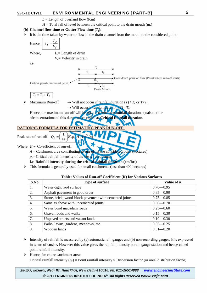
6L = Length of overland flow (Km)H = Total fall of level between the critical point to the drain mouth (m.)
(b) Channel flow time or Gutter Flow time (Tf): It is the time taken by water to flow in the drain channel from the mouth to the considered point.
Hence, df
d
LT
V
Where, Ld= Length of drainVd= Velocity in drain
i.e.
c i fT T T
Maximum Run-off Will not occur if rainfall duration (T) >Tc or T<Tc
Will occur if rainfall duration (T) =Tc.Hence, the maximum run-off will be obtained when the rainfall duration equals to timeofconcentrationand this duration are called as Critical Rainfall duration.
RATIONAL FORMULA FOR ESTIMATING PEAK RUN-OFF:
Peak rate of run-off. 31. . ( / )
36p cQ K p A m s
Where, K Co-efficient of run-offA = Catchment area contributing to run-off at the considered point (hectares)pc= Critical rainfall intensity of the design frequency.i.e. Rainfall intensity during the critical rainfall duration (cm/hr.)
This formula is generally used for small catchments (less than 400 hectares)
Table: Values of Run-off Coefficient (K) for Various SurfacesS.No. Type of surface Value of K1. Water-tight roof surface 0.70—0.952. Asphalt pavement in good order 0.85—0.903. Stone, brick, wood-block pavement with cemented joints 0.75—0.854. Same as above with uncemented joints 0.50—0.705. Water bond macadam roads 0.25—0.606. Gravel roads and walks 0.15—0.307. Unpaved streets and vacant lands 0.10—0.308. Parks, lawns, gardens, meadows, etc. 0.05—0.259. Wooden lands 0.01—0.20
Intensity of rainfall is measured by (a) automatic rain gauges and (b) non-recording gauges. It is expressedin terms of cm/hr. However this value gives the rainfall intensity at rain gauge station and hence calledpoint rainfall intensity.
Hence, for entire catchment area:
Critical rainfall intensity (pc) = Point rainfall intensity Dispersion factor (or areal distribution factor)
SSC-JE CIVIL ENVIRONMENTAL ENGINEERING [PART-B]
28-B/7, JiaSarai, Near IIT, HauzKhas, New Delhi-110016. Ph. 011-26514888. www.engineersinstitute.com© 2017 ENGINEERS INSTITUTE OF INDIA® .All Rights Reserved www.sscje.com
7
HYDRAULIC DESIGN OF SEWERS:Difference in design of water supply pipes and sewer pipes:
(i) Water supply pipes carry pure water without containing any kind of solid particles but sewer pipes containssewage containing suspended solid particles.
Hence sewer pipes are laid at such a gradient so as to generate self-cleansing velocities at differentpossible discharges to avoid silting or clogging of sewers.
(ii) Water supply pipes carry water under pressure but sewer pipes carry sewage under gravity.
Provision of free-board in sewer:Table: Values of Freeboard to be adopted for the design of S.W. Drains
Peak discharge in the drain for which designed, in cumecs Freeboard to be left in metersBelow 0.3 0.30.3—1.0 0.4
1—5 0.55—10 0.6
10—30 0.7530—150 0.90
More than 150 1.0
Determination of Flow velocities in sewers and drains: The sewers and drains are generally designed as open channels except in cases where it is required to
design as flowing under pressure e.g. Inverted siphons.
1. Chezy’s Formula: Velocity of flow in channel
. ( / )V C r i m s
Where r = Hydraulic mean radiusi = Hydraulic gradient equal to ground slope for uniform flowC= Chezy’s constant
Hence, Discharge, . .Q AV where A Flow area.
V Velocity as calculated above Chezy’s constant depends upon various factors such as the shape and size of the channel, roughness of
channel surface, hydraulic characteristics of channel etc. Chezy’s constant ‘C’ is found by:(a) Kutter’s Formula:
0.00155 123
0.001551 23 .
i nC
n
i r
Where, n = Rugosity coefficient depending upon the type of channel surface.i = Bed slope of sewer for uniform flows.r = Hydraulic mean radius.

SSC-JE CIVIL ENVIRONMENTAL ENGINEERING [PART-B]
28-B/7, JiaSarai, Near IIT, HauzKhas, New Delhi-110016. Ph. 011-26514888. www.engineersinstitute.com© 2017 ENGINEERS INSTITUTE OF INDIA® .All Rights Reserved www.sscje.com
8Table: Mannings or Kutter’sRugosity Coefficients (n)
S.No.
(1)
Pipe Material
(2)
Values of n atGood interior surface
condition(3)
full depth forFair interior surface
condition*(4)
1. Salt glazed stoneware pipes 0.012 0.0142. Cement concrete pipes 0.013 0.0153. Cast-iron pipes 0.012 0.0134. Brick, unglazed sewers/drains 0.013 0.0155. Asbestos cement 0.011 0.0126. Plastic (smooth) pipes 0.011 0.011
S.No. Type of the inside surface of the sewer ordrain
Value of K
1. Very smooth surfaces. 0.112. Smooth brick and concrete surfaces. 0.293. Rough brick and concrete surfaces. 0.504. Smooth rubble and masonry surfaces. 0.835. Good earthen channels. 1.546. Rough earthen channels 3.17
2. Manning’s Formula:
Velocity,2 / 3 1/ 21
. .V r in where, n = manning’s constant or Kutter’srugosity coefficient
(r, i has same meaning as mentioned above)
Maximum and Minimum Velocities: The flow velocities in the sewers should be such that neither the suspended materials get silted up nor the
sewer pipes material get scoured out.
(A)Minimum velocities: The velocity which will even scour the deposited particles of a given size is known as self-cleansing
velocity.
Shield’s expression for self-cleansing velocity:Self-cleansingvelocity, Vs:
'( 1)sV C Kd G Where, value of
K = 0.04 for inorganic matters present in sewageK = 0.6 for organic matters present in sewaged' = Diameter of grainG = Specific gravity (Inorganic = 2.65 organic = 1.2)C = chezy’s constant.
Where Chezy’s constant
(i)8
'
gC
f where f ’ = friction factor
g = 9.81 m/s2

SSC-JE CIVIL ENVIRONMENTAL ENGINEERING [PART-B]
28-B/7, JiaSarai, Near IIT, HauzKhas, New Delhi-110016. Ph. 011-26514888. www.engineersinstitute.com© 2017 ENGINEERS INSTITUTE OF INDIA® .All Rights Reserved www.sscje.com
9………. From Darcy-weisbachformula.
(ii) 1/ 61.C r
n …… from manning’s formula
A minimum velocity 0.45 m/s. and an average velocity 0.90 m/sare developed in sewers to remove sandimpurities up to 1 mm diameter and organic particles up to 5mm. diameter.
Minimum velocity generated in the sewer:-(i) Prevent the sewage from getting stale and preventing the evolution of foul gases.(ii) Keep the sewer size under control.
National Building Organisation (N.B.O) of India’s recommendation for gradients are:
Table : N.B.O. Recommendations for Small SewersDia. Of the
sewer in mmGradient required to generate self
cleansing velocityVelocity generated in the sewer when
running half full, for which depth, smallsewers are usually designed
100 1 in 60 0.58 m/sec150 1 in 100 0.61 m/sec225 1 in 120 0.79 m/sec
(B) Maximum Velocities : The maximum velocity should be such that it may not cause scouring and wear and tear of the pipe
material. Which ultimately reduces their life span and carrying capacities.Table : Non-scouring Limiting Velocities in Sewers and Drains
S.No. Sewer Material Limiting velocity in m/sec1. Vitrified tiles and glazed bricks 4.5—5.52. Cast iron sewers 3.5—4.53. Stone ware sewers 3.0—4.04. Cement concrete sewers 2.5—3.05. Ordinary brick-lined sewers 1.5—2.56. Earthen channels 0.6—1.2
Hydraulic Characteristics of Circular sewer sections running full or partially full.Consider a circular section as shown in figure:
Figure : Partially filled circular sewer section
When running full,

SSC-JE CIVIL ENVIRONMENTAL ENGINEERING [PART-B]
28-B/7, JiaSarai, Near IIT, HauzKhas, New Delhi-110016. Ph. 011-26514888. www.engineersinstitute.com© 2017 ENGINEERS INSTITUTE OF INDIA® .All Rights Reserved www.sscje.com
10
(i) Hydraulic Mean depth or ,
2( ) 4( )
wetted Perimeter (P)
DArea AR
D
OR
Hydraulic mean radius (H.M.D.)4
DR
(ii) Velocity, 2 / 31.V r i
n where i = Bed slope
(iii) Discharge Q = A.V.
When running partially:
(iv) Depth, 1 cos.2 2
Dd
Proportionate Depth1
1 cos2 2
d
D
(v) Cross-section area,2 sin
4 360 2
Da
Proportionate areasin
360 2
a
A
(vi) Wetted perimeter, . .360
p D
Proportionate perimeter,360
p
P
(vii) Hydraulic mean depth (H.M.D.)
360 .sin1
4 2
a Dr
p
Proportionate H.M.D.360 .sin
12
r
R
(viii) Velocity, 2 / 31v r i
n
Proportionate velocity2 / 3
2 / 3.
v r
V R [Assuming n as constant with depth]
2/3360 .sin
12
(ix) Discharge, .q a v
Proportionate discharge2 / 3
sin 360 .sin. . 1
360 2 2
q a v
Q A V
Hence: If rugosityco-efficient ‘C’ is assumed to be independent of depth:(a) Velocity will be maximum

SSC-JE CIVIL ENVIRONMENTAL ENGINEERING [PART-B]
28-B/7, JiaSarai, Near IIT, HauzKhas, New Delhi-110016. Ph. 011-26514888. www.engineersinstitute.com© 2017 ENGINEERS INSTITUTE OF INDIA® .All Rights Reserved www.sscje.com
11
When depth of flow, 0.81. ,d D and it is approximately 12.5% greater than when running full.
(b) Discharge will be maximum
When depth of flow, 0.95d D and it is approximately 7% greater than when running full.
0.5 ;D
d then 1.0
V
v
where, d is depth of flowv is flow velocity at depth dD is the diameter of sewerV is flow velocity at full flow.
Note: As the velocities and discharges both decrease and become lesser than those at full flow. However,
the decline in velocities is not so sharp as the decline in discharges, because theare (on which discharge depends)reduces much faster as compared to hydraulic mean depth (on which velocity depends).
Variation of ‘n’: The value of ‘n’ increases with decrease in depths and it varies up to 20% or more with depth. Hence, variation of ‘n’ reduces the proportionate velocity and discharges at lower depths. Minimum gradients are sufficient as long as circular sewers flow more than half full but when flow depth
reduces to less than 0.3 times the full depth, the gradient should be increased.Note: Sewers up to 400 mm diameter is designed to run at 1/2 depth sewers between 400 mm and 900 mm.
diameter is designed to run at 2/3 depth and larger sewers for 3/4 depth.A circular section is advantageous over other sections like U-shape, parabolic shape etc. because:
(a) Easy to manufacture.(b) A circular section provides the maximum area for a given perimeter i.e. most efficient sections.(c) It utilizes minimum quantities of materials.
SEWERS: CONSTRUCTION, MAINTENANCE AND REQUIRED APPURTENANCES SHAPES OFSEWER PIPES:
0.5d
D
SSC-JE CIVIL ENVIRONMENTAL ENGINEERING [PART-B]
28-B/7, JiaSarai, Near IIT, HauzKhas, New Delhi-110016. Ph. 011-26514888. www.engineersinstitute.com© 2017 ENGINEERS INSTITUTE OF INDIA® .All Rights Reserved www.sscje.com
11
When depth of flow, 0.81. ,d D and it is approximately 12.5% greater than when running full.
(b) Discharge will be maximum
When depth of flow, 0.95d D and it is approximately 7% greater than when running full.
0.5 ;D
d then 1.0
V
v
where, d is depth of flowv is flow velocity at depth dD is the diameter of sewerV is flow velocity at full flow.
Note: As the velocities and discharges both decrease and become lesser than those at full flow. However,
the decline in velocities is not so sharp as the decline in discharges, because theare (on which discharge depends)reduces much faster as compared to hydraulic mean depth (on which velocity depends).
Variation of ‘n’: The value of ‘n’ increases with decrease in depths and it varies up to 20% or more with depth. Hence, variation of ‘n’ reduces the proportionate velocity and discharges at lower depths. Minimum gradients are sufficient as long as circular sewers flow more than half full but when flow depth
reduces to less than 0.3 times the full depth, the gradient should be increased.Note: Sewers up to 400 mm diameter is designed to run at 1/2 depth sewers between 400 mm and 900 mm.
diameter is designed to run at 2/3 depth and larger sewers for 3/4 depth.A circular section is advantageous over other sections like U-shape, parabolic shape etc. because:
(a) Easy to manufacture.(b) A circular section provides the maximum area for a given perimeter i.e. most efficient sections.(c) It utilizes minimum quantities of materials.
SEWERS: CONSTRUCTION, MAINTENANCE AND REQUIRED APPURTENANCES SHAPES OFSEWER PIPES:

SSC-JE CIVIL ENVIRONMENTAL ENGINEERING [PART-B]
28-B/7, JiaSarai, Near IIT, HauzKhas, New Delhi-110016. Ph. 011-26514888. www.engineersinstitute.com© 2017 ENGINEERS INSTITUTE OF INDIA® .All Rights Reserved www.sscje.com
12SSC-JE CIVIL ENVIRONMENTAL ENGINEERING [PART-B]
28-B/7, JiaSarai, Near IIT, HauzKhas, New Delhi-110016. Ph. 011-26514888. www.engineersinstitute.com© 2017 ENGINEERS INSTITUTE OF INDIA® .All Rights Reserved www.sscje.com
12SSC-JE CIVIL ENVIRONMENTAL ENGINEERING [PART-B]
28-B/7, JiaSarai, Near IIT, HauzKhas, New Delhi-110016. Ph. 011-26514888. www.engineersinstitute.com© 2017 ENGINEERS INSTITUTE OF INDIA® .All Rights Reserved www.sscje.com
12

SSC-JE CIVIL ENVIRONMENTAL ENGINEERING [PART-B]
28-B/7, JiaSarai, Near IIT, HauzKhas, New Delhi-110016. Ph. 011-26514888. www.engineersinstitute.com© 2017 ENGINEERS INSTITUTE OF INDIA® .All Rights Reserved www.sscje.com
13
Figure :Different Shapes of Sewer Sections.
Egg-Shaped Sewer Two circular sewers one having larger and other having smaller diameters are combined together to form
an egg-shaped sewer. Circular sewers are very effective only when the sewers run at least half-full. When the depth reduces
below this, velocity will reduce considerably. During dry weather conditions, circular sewer is very less effective because velocity is very low. In dry weather conditions, the smaller portion of egg-shaped sewer is very effective whereas in rainy
season, full section takes part in flow. In circular sewers, fluctuation in discharge and velocity is very high as large as 25 times so, egg-shaped
sewer is more efficient as fluctuation in velocity will be relatively very low.
Forces acting on sewer pipes are:(a) Internal pressure of sewage(b) Pressure due to external loads(c) Temperature stresses(d) Flexural stresses
Factors affecting selection of sewer materials are:(a) Resistance to corrosion(b) Resistance to abrasion(c) Strength and durability(d) Light weight, imperviousness(e) Economy and cost(f) Hydraulically efficient
Note:- 2 sections are called hydraulically equivalent when they carry equal discharge while running full, whenthey are laid on same grade and are of same material.
If a circular section is hydraulically equivalent to a square section then,Q0 = QII
SSC-JE CIVIL ENVIRONMENTAL ENGINEERING [PART-B]
28-B/7, JiaSarai, Near IIT, HauzKhas, New Delhi-110016. Ph. 011-26514888. www.engineersinstitute.com© 2017 ENGINEERS INSTITUTE OF INDIA® .All Rights Reserved www.sscje.com
14
2/3 1/2 2/3 1/21 1. . 'R S A r S A
n n
2/3 2/3
2 2. .4 4 4
D BD B
1.1D B
.9B D
TYPE OF SEWERS:1. Asbestos Cement Sewer: Manufactured from a mixture of asbestos fibers, silica and cement. Available in sizes of 100 mm to 900mm diameter and 4m length Interior surface of this is exceptionally smooth (N = 0.011) thus providing an excellent hydraulically
efficient sewer. Structurally not strong enough to bear huge compressive stresses. They are susceptible to corrosion by sulphuricacid produced by sanitary waste water.
2. Plain Cement Concrete: Available in small sizes i.e. up to 450 mm diameter.
Mix used is1
1:1 :3,2
with maximum aggregate size of 6 mm. W/c ratio: 0.5 to 0.7.
3. Reinforced cement concrete (R.C.C.) Pipes: Available in sizes up to 1800 mm. or even up to 4500 mm. These are provided with circumferential reinforcement to carry internal or external stresses and a nominal
longitudinal reinforcement equal to 0.25% of the cross-sectional area of concrete.
As per IS: 458-1988, Non-pressure R.C.C. pipes are classified as:(a) NP2 pipes: Light duty R.C.C. non-pressure pipes. Used for drainage and irrigation purpose i.e. culverts Carrying light traffic. Thickness varies from 25 mm for 80 mm. diameter to 110 mm for 2200 mm diameter Pipe.
(b) NP3 pipe: Medium duty non-pressure pipes. Used for culverts carrying medium traffic. Thickness varies from 25mm for 80 mm. diameters to 215 mm. for 2600 mm. diameter Pipe.
(c) NP4 pipe: Heavy duty non-pressure pipe. Used for culverts carrying heavy traffic, e.g. Railway loadings.
Note: The unreinforced and reinforced concrete pipes are capable of withstanding a test pressure of 7mheadof
water. R.C.C. pressure pipes are classified as P1, P2 and P3 pipes and these are used for carrying water supplies
under pressure and generally not used as sewers.

SSC-JE CIVIL ENVIRONMENTAL ENGINEERING [PART-B]
28-B/7, JiaSarai, Near IIT, HauzKhas, New Delhi-110016. Ph. 011-26514888. www.engineersinstitute.com© 2017 ENGINEERS INSTITUTE OF INDIA® .All Rights Reserved www.sscje.com
15
Hume steel pipe: These are R.C.C. pipes patented under this name. It consists of thin steel shells coated from inside with cement mortar by centrifugal process. Thickness of inside coatings varies from 12mm – 30 mm and thickness of outside coatings is 25 mm for
pipes up to 1 metre diameter and is 37.5 mm for pipes of larger diameter. It is available in sizes ranging between 10 cm to 2.4 m. in diameter and lengths vary from 0.9 – 2.4 m.
Problems of concrete pipes and their remedies: These easily get corroded and pitted by the action of Sulphuric acid produced from H2S gas evolved from
the stale sewage or from such other chemicals present in sewage. Sewers can be protected from Hydrogen sulphide(H2S) corrosion by means of the following :
(a) By prohibiting the entry of wastes containing sulphides.(b) Aerating and chlorinating the sewage.(c) Reducing the sulphate contents by pre-treating the sewage.(d) By adequately ventilating the sewers and by making the sewers to run full.(e) By lining their interiors with vitrified clay linings.
To buy Complete Course Materials
Contact: 9990657855, 9278800100Email : [email protected] Website : www.sscje.com
Classroom Coaching Program
Postal Coaching Program
Online Test Series