ssd2805 mipi bridge evaluation k it user's guide · keywords: solomon ssd2805, ssd2805...
TRANSCRIPT

Keywords: Solomon SSD2805, SSD2805 evaluation kit, 1.54" MIPI display LG LH154Q01, Microchip PIC32MX250F128D
User's Guide - SSD2805 MIPI Bridge Evaluation Kit
Document version 0.1
All Rights Reserved Page 1
SSD2805 MIPI Bridge Evaluation Kit
User's Guide
TechToys Company
Unit 12, 9/F, Block B
Sun Fung Centre
88 Kwok Shui Road
Tsuen Wan
Hong Kong
Tel: 852-28576267
Fax: 852-28576216
Web site: www.TechToys.com.hk

Keywords: Solomon SSD2805, SSD2805 evaluation kit, 1.54" MIPI display LG LH154Q01, Microchip PIC32MX250F128D
User's Guide - SSD2805 MIPI Bridge Evaluation Kit
Document version 0.1
All Rights Reserved Page 2
Table of Contents
Page
Chapter 1. Overview 3
1.1 Introduction 3
1.2 Evaluation Kit Layout 4
1.3 Modes of Operation 6
1.4 Connecting to Host Processor 8
1.5 Connecting to MIPI Display 9
Chapter 2. Getting Started 10
2.1 Display the First Pixel 10
2.2 Hardware required 10
2.3 Software required 10
2.4 Procedures to Start Programming 11
Appendix A. Something about MIPI 15
References 16
Keywords: Solomon SSD2805, SSD2805 evaluation kit, 1.54" MIPI display LG LH154Q01, Microchip PIC32MX250F128D
User's Guide - SSD2805 MIPI Bridge Evaluation Kit
Document version 0.1
All Rights Reserved Page 3
Chapter 1. Overview
1.1 Introduction
The MIPI Alliance (MIPI) is an open membership organization that develops
interface specifications for mobile industries. It was founded by industry leaders
including ARM, Intel, Nokia, Samsung, STMicroelectronics and Texas Instruments.i
In year 2003, the MIPI Alliance has proposed a new interface standard known as
Display Serial Interfaceii (DSI) to replace traditional RGB interface for mobile
gadgets. The main goal of the new standard is to develop a new high-speed interface
to minimize peripheral pincount, power comsumption, lower electromagnetic
interference, and lower product cost.
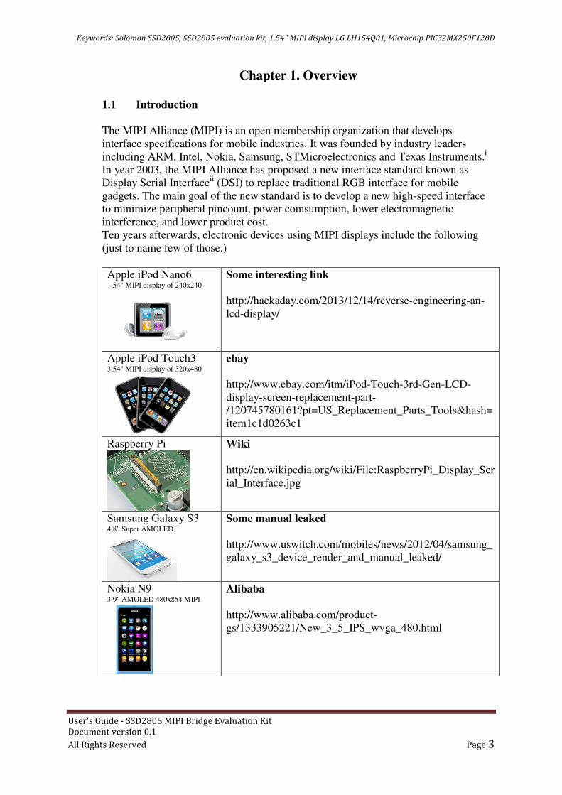
Ten years afterwards, electronic devices using MIPI displays include the following
(just to name few of those.)
Apple iPod Nano6 1.54" MIPI display of 240x240
Some interesting link
http://hackaday.com/2013/12/14/reverse-engineering-an-
lcd-display/
Apple iPod Touch3 3.54" MIPI display of 320x480
ebay
http://www.ebay.com/itm/iPod-Touch-3rd-Gen-LCD-
display-screen-replacement-part-
/120745780161?pt=US_Replacement_Parts_Tools&hash=
item1c1d0263c1
Raspberry Pi
Wiki
http://en.wikipedia.org/wiki/File:RaspberryPi_Display_Ser
ial_Interface.jpg
Samsung Galaxy S3 4.8" Super AMOLED
Some manual leaked
http://www.uswitch.com/mobiles/news/2012/04/samsung_
galaxy_s3_device_render_and_manual_leaked/
Nokia N9 3.9" AMOLED 480x854 MIPI
Alibaba
http://www.alibaba.com/product-
gs/1333905221/New_3_5_IPS_wvga_480.html

Keywords: Solomon SSD2805, SSD2805 evaluation kit, 1.54" MIPI display LG LH154Q01, Microchip PIC32MX250F128D
User's Guide - SSD2805 MIPI Bridge Evaluation Kit
Document version 0.1
All Rights Reserved Page 4
Although there are high-end processors with built-in MIPI driver, tons of
microcontrollers and microprocessors with traditional parallel LCD interfaces (RGB
and MCU interface) are still alive in the market, especially for low-range MCUs a
MIPI interface is not standard.
Solomon Systech MIPI Master Bridge Chips SSD2805 is an IC that converts
traditional MCU & RGB interface to MIPI interface.
Evaluation kit described in this manual provides a reference design for SSD2805.
1.2 Evaluation Kit Layout
Representations of the board layout are shown in Figure 1-1.
Key features include:
1. SSD2805 MIPI Bridge IC.
2. On-board oscillator (Y1) for an active clock signal at 20MHz.
3. Selection switch (S1) for different interface options.
4. MOSFET switch (Q1) to control VDDIO.
5. Linear regulator (U1) XC6206(1.8V) for VDDA and VDDD.
6. 40 pins 2.54mm header (P1) wiring all input signals for SSD2805.
7. 8 pins 2.54mm header (P2) is a jumper switch for the desired pin to
drive VSYNC/WRX of SSD2805 from Samtec MEC1-160-02 edge mount
socket (J1). The reason for this is to make this board compatible with
Microchip's Explorer 16.
8. 20 pins 2.54mm header (P3) wires all differential output from SSD2805 plus
3.3V, 1.8V, EXT_5V, VDDIO and GND.
9. FPC connector (J2) in 0.5mm pitch. This is a down contact connector for DSI
signal of SSD2805 together with peripherals (UART/SPI/I2C) routed
directly from J1.
10. Samtec MEC1-160-02 edge mount socket (J1) is a high speed socket routed to
P1for all SSD2805 input signals. Peripherals and GPIOs described in point 9
above are routed directly from J1 to J2. With compatibility with Microchip's
Explorer 16 board in mind, socket J1 gives a clean and low-noise interface for
the host MCU/microprocessor. One may design his own host board with
specification given by the document (Revision E - recommended mating
card layout for MEC1-XX-XX-XX-D-EMX-XX) released by Samtec.

Keywords: Solomon SSD2805, SSD2805 evaluation kit, 1.54" MIPI display LG LH154Q01, Microchip PIC32MX250F128D
User's Guide - SSD2805 MIPI Bridge Evaluation Kit
Document version 0.1
All Rights Reserved Page 5
Figure 1-1 Board Layout
2
3
1
4
5
6
7
8 9
10
Keywords: Solomon SSD2805, SSD2805 evaluation kit, 1.54" MIPI display LG LH154Q01, Microchip PIC32MX250F128D
User's Guide - SSD2805 MIPI Bridge Evaluation Kit
Document version 0.1
All Rights Reserved Page 6
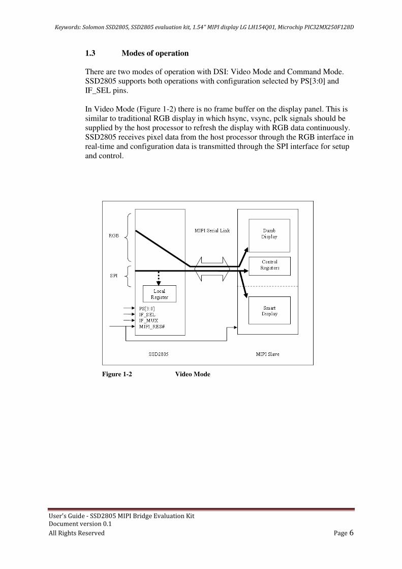
1.3 Modes of operation
There are two modes of operation with DSI: Video Mode and Command Mode.
SSD2805 supports both operations with configuration selected by PS[3:0] and
IF_SEL pins.
In Video Mode (Figure 1-2) there is no frame buffer on the display panel. This is
similar to traditional RGB display in which hsync, vsync, pclk signals should be
supplied by the host processor to refresh the display with RGB data continuously.
SSD2805 receives pixel data from the host processor through the RGB interface in
real-time and configuration data is transmitted through the SPI interface for setup
and control.
Figure 1-2 Video Mode

Keywords: Solomon SSD2805, SSD2805 evaluation kit, 1.54" MIPI display LG LH154Q01, Microchip PIC32MX250F128D
User's Guide - SSD2805 MIPI Bridge Evaluation Kit
Document version 0.1
All Rights Reserved Page 7
In Command Mode (Figure 1-3) there is an internal display controller with frame
buffer on the display panel. This mode is similar to traditional MCU model in
which CS#, DC, WR#, RD#, and DATA should be supplied by the host processor.
SSD2805 supports 8-bit and 16-bit MCU interface with CSX as the chip select,
DCX for data/command select, WRX for write enable and RDX as read enable.
Table 1-1 shows settings for different interface modes. When to use Video Mode
or Command Mode depends entirely on the display.
For example, to drive the 1.54" iPod Nano 6 display Command Mode should be
chosen with IF_SEL high 1 for MCU interface.
On the other hand, 3.54" iPod Touch 3 uses Video Mode therefore the host
processor shall be sending RGB signal with IF_SEL set 0 for RGB_SPI mode.
Figure 1-3 Command Mode

Keywords: Solomon SSD2805, SSD2805 evaluation kit, 1.54" MIPI display LG LH154Q01, Microchip PIC32MX250F128D
User's Guide - SSD2805 MIPI Bridge Evaluation Kit
Document version 0.1
All Rights Reserved Page 8
Mode Control Pins
Video Mode
PS[1:0] = 01 (8-bit SPI 3 wire)
IF_SEL = 0 (RGB + SPI)
LANE_SEL = 1 (2 data lanes)
Command Mode
PS[1:0] = 11 (no SPI)
PS[3:2] = 00 (8 bit 8080 MCU interface)
IF_SEL = 1(MCU interface)
IF_MUX = 0 (MUX scheme 1)
LANE_SEL = 0 (1 data lane)
Command Mode
PS[1:0] = 11 (no SPI)
PS[3:2] = 01 (16 bit 8080 MCU interface)
IF_SEL = 1(MCU interface)
IF_MUX = 0 (MUX scheme 1)
LANE_SEL = 0 (1 data lane)
Table 1-1 Selection switch setup for different interface mode
1.4 Connecting to Host Processor
Mate with the Samtec edge mount socket (Figure 1-4). Footprint of the mating
card can be downloaded from Samtec web site from the web link below.
http://www.samtec.com/technical-specifications/Default.aspx?SeriesMaster=MEC1-EM
Figure 1-4 Mating card for Samtec socket
Keywords: Solomon SSD2805, SSD2805 evaluation kit, 1.54" MIPI display LG LH154Q01, Microchip PIC32MX250F128D
User's Guide - SSD2805 MIPI Bridge Evaluation Kit
Document version 0.1
All Rights Reserved Page 9
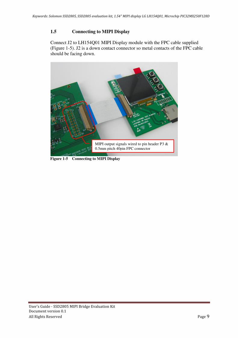
1.5 Connecting to MIPI Display
Connect J2 to LH154Q01 MIPI Display module with the FPC cable supplied
(Figure 1-5). J2 is a down contact connector so metal contacts of the FPC cable
should be facing down.
Figure 1-5 Connecting to MIPI Display
MIPI output signals wired to pin header P3 &
0.5mm pitch 40pin FPC connector

Keywords: Solomon SSD2805, SSD2805 evaluation kit, 1.54" MIPI display LG LH154Q01, Microchip PIC32MX250F128D
User's Guide - SSD2805 MIPI Bridge Evaluation Kit
Document version 0.1
All Rights Reserved Page 10
Chapter 2. Getting Started
2.1 Display the First Pixel
This section focuses on software to drive SSD2805. There are two interface
modes possible: MCU mode and RGB mode. Program described in this chapter
uses MCU mode with no operating system or graphics library assumed.
2.2 Hardware required
• PCB with Microchip PIC32MX250F128D 32-bit microcontroller as the
host processor (PCB version 23122013)
• SSD2805 MIPI Bridge EVK (PCB rev 27092013)
• 1.54" MIPI display LH154Q01 on PCB, LH154Q01 AP Module (PCB
Rev 01112013)
• Debugger device Microchip ICD3 or PICKit3
• PC compatible system with one USB port, or a powered USB hub
2.3 Software required
• MPLAB X Integrated Development Environment (IDE) version 2.00
or later
• XC32 C compiler v1.20 or later. Because XC32 is an ANSI C compiler,
this program applies other microcontroller with C compiler as well
• Program source code from the same web page you have downloaded
this guide under Doc 08.
Keywords: Solomon SSD2805, SSD2805 evaluation kit, 1.54" MIPI display LG LH154Q01, Microchip PIC32MX250F128D
User's Guide - SSD2805 MIPI Bridge Evaluation Kit
Document version 0.1
All Rights Reserved Page 11
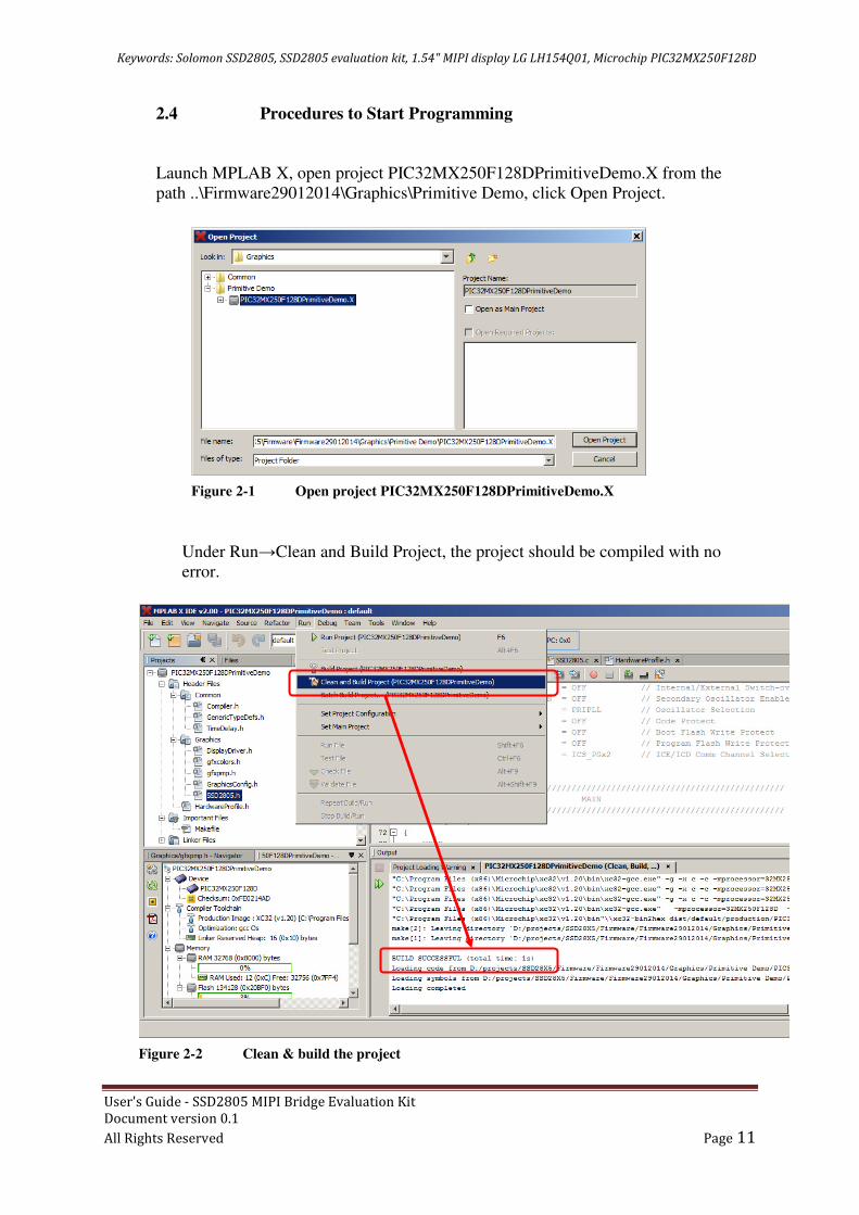
2.4 Procedures to Start Programming
Launch MPLAB X, open project PIC32MX250F128DPrimitiveDemo.X from the
path ..\Firmware29012014\Graphics\Primitive Demo, click Open Project.
Under Run→Clean and Build Project, the project should be compiled with no
error.
Figure 2-1 Open project PIC32MX250F128DPrimitiveDemo.X
Figure 2-2 Clean & build the project

Keywords: Solomon SSD2805, SSD2805 evaluation kit, 1.54" MIPI display LG LH154Q01, Microchip PIC32MX250F128D
User's Guide - SSD2805 MIPI Bridge Evaluation Kit
Document version 0.1
All Rights Reserved Page 12
Put up the boards as shown in Figure 2-3 below. Make sure jumper P2 and S1 are
correctly set.
Connect a debugger to P1. It is possible to use a PICKit 3 (Figure 2-4) or ICD3
via an adapter (Figure 2-5). Finally, supply 5V with USB port.
Figure 2-3 Jumper and selection switch settings
Figure 2-4 Connect to PICKit 3

Keywords: Solomon SSD2805, SSD2805 evaluation kit, 1.54" MIPI display LG LH154Q01, Microchip PIC32MX250F128D
User's Guide - SSD2805 MIPI Bridge Evaluation Kit
Document version 0.1
All Rights Reserved Page 13
From MPLAB X, click Debug Project.
Figure 2-5 Connect to ICD3
Figure 2-6 Debug Project

Keywords: Solomon SSD2805, SSD2805 evaluation kit, 1.54" MIPI display LG LH154Q01, Microchip PIC32MX250F128D
User's Guide - SSD2805 MIPI Bridge Evaluation Kit
Document version 0.1
All Rights Reserved Page 14
The MIPI display will be refreshed with blue and yellow color.
Figure 2-7 MIPI display refreshed with a single color

Keywords: Solomon SSD2805, SSD2805 evaluation kit, 1.54" MIPI display LG LH154Q01, Microchip PIC32MX250F128D
User's Guide - SSD2805 MIPI Bridge Evaluation Kit
Document version 0.1
All Rights Reserved Page 15
APPENDIX A Something about MIPI
There are two useful sources to understand DSI.
1. MIPI Alliance Standard for Display Serial Interface V1.0 : 79 pages
2. MIPI Alliance Standard for Display Command Set : 131 pages
An extract from the first document is summarized below:
"The Display Serial Interface (DSI) specification defines protocols between a host
processor and peripheral devices that adhere to MIPI Alliance specifications for
mobile device interfaces.....
By standardizing this interface, components may be developed that provide higher
performance, lower power, less EMI and fewer pins than current devices, while
maintaining compatibility across products from multiple vendors."
"For display modules with a display controller and frame buffer, DSI shares a
common command set with MIPI Alliance Standard for Display Bus Interface."
Standardization leads to a common command set defined in the second document.
An extract of the second document is summarized below:
"The Display Command Set (DCS) specification defines display module behavior
for devices that adhere to the MIPI specifications for mobile device host processor,
and display interfaces in an abstract, device independent way....
Implementing the DCS standard reduces the time-to-market and design cost of
mobile devices by simplifying the interconnection of products from different
manufacturers."
What it really means to programmers is that, the command written to a MIPI is the
same across different MIPI displays or different vendors.
Table below gives an example comparing commands for three MIPI displays for
Sleep In/Out, Display ON/OFF against the Display Command Set laid on the
specification.
Operation DCS
Specification
LH350H01
3.54" MIPI
display for iPod
Touch3
LH154Q01
1.54" MIPI
display for
iPod Nano 6
7" MIPI
display for a
tablet
Soft Reset 0x01 - 0x01 0x01
Sleep Out 0x11 0x11 0x11 0x11
Sleep In 0x10 0x10 0x10 0x10
Display On 0x29 0x29 0x29 -
Display Off 0x28 0x28 0x28 -

Keywords: Solomon SSD2805, SSD2805 evaluation kit, 1.54" MIPI display LG LH154Q01, Microchip PIC32MX250F128D
User's Guide - SSD2805 MIPI Bridge Evaluation Kit
Document version 0.1
All Rights Reserved Page 16
References i Mobile Industry Processor Interface from Wikipedia
Web site: http://en.wikipedia.org/wiki/Mobile_Industry_Processor_Interface
ii Display Serial Interface from Wiki
http://en.wikipedia.org/wiki/Display_Serial_Interface