mipi devcon 2016: a developer's guide to mipi i3c implementation
TRANSCRIPT

A Developer’s Guide to MIPI I3C Implementation
Ken Foust, Intel MIPI Sensor WG Chair

Outline • Introduction to MIPI I3C
• MIPI I3C feature descriptions • Implementation guidelines
• Legacy Device Support • HDR Modes • Timing Control • Varied Topologies
• Summarized good design practices
2

Welcome to MIPI I3CSM!
• An exciting new addition to the MIPI catalog
• Unifies key attributes of I2C and SPI, commonly used for Sensors
• Improves capabilities and performance

I3CSM for Ubiquitous Low Speed Interfacing • Anywhere sensors are used, I3C belongs • Aimed toward historical I2C, SPI and UART applications
in…
4

What is MIPI I3CSM? • Innovative new 2-Wire Sensor interface • Key features address historical pain points
• In-band Interrupt, Dynamic Addressing, Multi-Master, Standardized Commands, Time Control, Hot-Join, Error Detection and Recovery
• Plus… I2C Compatibility Low Power High Data Rates
~1/8ththePower! ~100TimesFaster!

Sensor Proliferation
Source:MIPI_Sensor_Interface_BoF_telco_14sep2012_v0.4.pdf

MIPI I3CSM Vision
TooManyI/Os!FragmentedInterfaces!

MIPI I3CSM Vision

There Are More Usages
Master Application Processor
Secondary Master GPS IC
Slave Accelerometer
Slave Magnetometer
Slave Gyroscope
Secondary Master Sensor Hub IC
SecondaryMaster
Master Application Processor
Secondary Master GPS IC
Slave Barometer
Secondary Master 9-axis Combo
IMU
Master Application Processor
Slave Accelerometer
Slave Detachable
Accelerometer
DynamicAddressing MulD-Drop/SecondaryMaster
DynamicAddressing/HotJoin
12.5MHzI2C-likeClockHDRModes(HighDataRate)
Examples:

MIPI I3CSM Feature: SDR Mode
• I3C SDR – The base interface • Up to 12.5 MHz I2C-like clocking with defined Open-Drain / Push-Pull
• Supports multiple classes of Devices • I3C Main Master
• SDR-only Main Master
• I3C Secondary Master • SDR-Only Secondary Master
• I3C Slave • SDR-Only Slave
• I2C slave
MIPI I3CSM Features
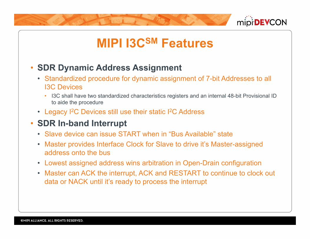
• SDR Dynamic Address Assignment • Standardized procedure for dynamic assignment of 7-bit Addresses to all
I3C Devices • I3C shall have two standardized characteristics registers and an internal 48-bit Provisional ID
to aide the procedure
• Legacy I2C Devices still use their static I2C Address
• SDR In-band Interrupt • Slave device can issue START when in “Bus Available” state • Master provides Interface Clock for Slave to drive it’s Master-assigned
address onto the bus • Lowest assigned address wins arbitration in Open-Drain configuration • Master can ACK the interrupt, ACK and RESTART to continue to clock out
data or NACK until it’s ready to process the interrupt

MIPI I3CSM Feature
• Hot-Join • Definition: Slaves that join the Bus after it is already started, whether because they were not powered previously
or because they were physically inserted into the Bus; the Hot-Join mechanism allows the Slave to notify the Master that it is ready to get a Dynamic Address.
• Allows Slaves to join the I3C Bus after it is already configured • Ideal for I3C Devices:
• mounted on the same board, but de-powered until needed • mounted on a module/board that is physically inserted after the I3C Bus has already been
configured
• Note: Such Devices shall not violate specified electrical limits and shall not disrupt the I3C lines during physical insertion
MIPI I3CSM Features
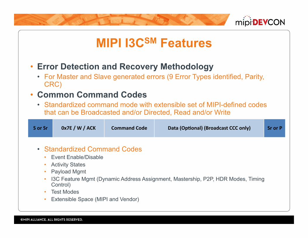
• Error Detection and Recovery Methodology • For Master and Slave generated errors (9 Error Types identified, Parity,
CRC) • Common Command Codes
• Standardized command mode with extensible set of MIPI-defined codes that can be Broadcasted and/or Directed, Read and/or Write
• Standardized Command Codes • Event Enable/Disable • Activity States • Payload Mgmt • I3C Feature Mgmt (Dynamic Address Assignment, Mastership, P2P, HDR Modes, Timing
Control) • Test Modes • Extensible Space (MIPI and Vendor)
SorSr 0x7E/W/ACK CommandCode Data(OpIonal)(BroadcastCCConly) SrorP

Guidelines - Legacy I2C Device Support • Fm and Fm+ Speeds Supported • 50ns Spike Filter (tSP) Needed for 12.5MHz I3C
Clocking
• Clock Stretching is Not Allowed – I3C SCL is Push/Pull • 20mA Open Drain Drivers (IOL) are Not Used • I2C Extended Addresses (10 bit) are Not Used
14
UM10204: I2C-bus specification and user manual Rev. 6
tSP: pulse width of spikes that must
be suppressed by the input filter

MIPI I3CSM Features
• I3C High Data Rate (HDR) Modes • Optionally supported beyond the base SDR mode: 12.5MHz, SDA/SCL
• HDR-DDR: Double Data Rate • HDR-TSL/TSP: Ternary Symbol
• Offer bit rates over 30Mbps at a fraction of the per bit power of I2C Fast Mode • Simple Slave-side digital implementations (guidelines provided in Specification) • Coexistent with legacy I2C Devices • Leverage rising and falling edges • Individually entered using broadcasted MIPI-defined Common Command Codes • Universally exited and restarted via MIPI-defined toggling patterns
• Allows non-HDR I3C Devices to “ignore” HDR transmissions I3C Msg1 Msg2 I3C
START BrdcstCCC EnterHDRx HDRCmd HDRData HDRRestartPaUern HDRCmd HDRData HDRExit
PaUern STOP
HDRRestart
HDRExit
MIPI I3CSM Features
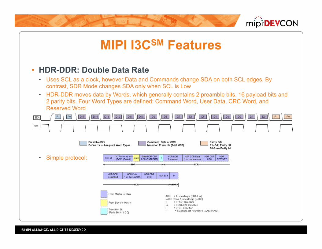
• HDR-DDR: Double Data Rate • Uses SCL as a clock, however Data and Commands change SDA on both SCL edges. By
contrast, SDR Mode changes SDA only when SCL is Low • HDR-DDR moves data by Words, which generally contains 2 preamble bits, 16 payload bits and
2 parity bits. Four Word Types are defined: Command Word, User Data, CRC Word, and Reserved Word
• Simple protocol:

MIPI I3CSM Features
• HDR-TSL/TSP: Ternary Symbol Coding • Ternary symbol coding for pure (TSP) and I2C legacy-inclusive (TSL) systems • Given a two-wire interface with ‘simultaneous’ transitions and no traditional clock, there are four
possible symbols available from 2’b00 to 2’b11 – Symbols: 0, 1, 2, 3
• At least one line must transition each period • Ideally, there are 3 possible “next” transition • Transition indices are used to efficiently encode Binary into Ternary • Allows only two transitions to cover all 0002 to 1112
• Simple protocol:
SDA 10
SCL
One symbol
11 01 01 00 11 00
HDR-TSL/TSP I2C and I3C SDR
vs
I3CSDR Msg1 Msg2 I3C
START BrdcstCCC EnterHDRx HDRCmd HDRDataHDR
RestartPaUern
HDRCmd HDRData HDRExitPaUern STOP

Guidelines - HDR Modes • Enter HDR Commands Supported
• HDR Exit Pattern detected by all I3C Devices
• Non-HDR Devices shall ignore I3C HDR bus traffic until the HDR Exit Pattern is detected
18
I3C Msg1 Msg2 I3C
START BrdcstCCC EnterHDRx HDRCmd HDRData HDRRestartPaUern HDRCmd HDRData HDRExit
PaUern STOP
HDRExit
MIPI I3CSM Features
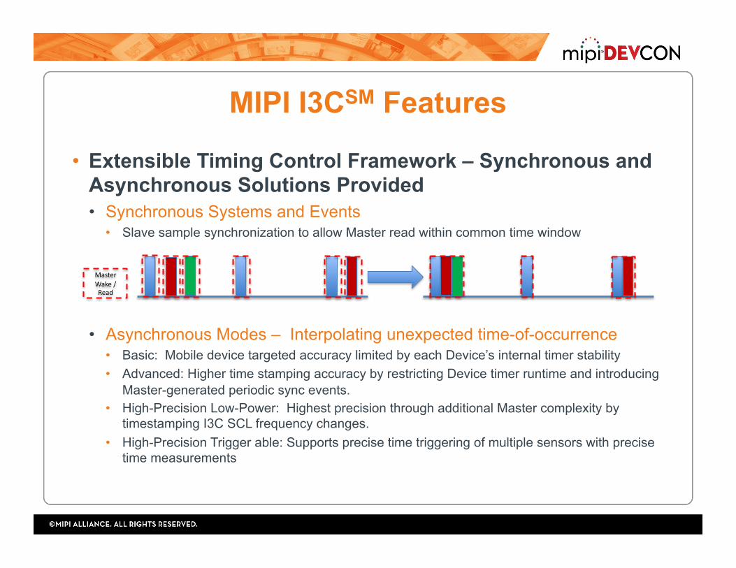
• Extensible Timing Control Framework – Synchronous and Asynchronous Solutions Provided • Synchronous Systems and Events
• Slave sample synchronization to allow Master read within common time window
• Asynchronous Modes – Interpolating unexpected time-of-occurrence • Basic: Mobile device targeted accuracy limited by each Device’s internal timer stability • Advanced: Higher time stamping accuracy by restricting Device timer runtime and introducing
Master-generated periodic sync events. • High-Precision Low-Power: Highest precision through additional Master complexity by
timestamping I3C SCL frequency changes. • High-Precision Trigger able: Supports precise time triggering of multiple sensors with precise
time measurements
MasterWake/Read

Guidelines - Timing Control • Sensor/Device Clock Accuracy
• Support exchange of timing information via I3C CCCs • Clock/Oscillator Frequency and Error (variation)
20

Guidelines - Varied Topologies
• Impacts on signal transition/transit times (maximum bus frequency) • SDA/SCL drive strength: “weaker” for lower power and interference vs “stronger” for faster over
larger topologies/loads • Trace length and material: short vs long and pcb vs cable • SCL/SDA pad capacitance • Clock to Data Turnaround Time (tSCO)
• Legacy I2C Devices impact maximum bus frequency (MHz) • Must run I3C at speeds/pulses beyond Spike Filter or slow Bus to that of slowest I2C Device
• Impacts on signal integrity/reliability • Device Location: close and far Devices can cause interference from reflections
21
I3C Master
I3C Slave I3C Slave
I3C Slave
Example

Summarized Good Design Practices • Thoroughly understand capability of coexistent Legacy I2C
Devices • 50ns Spike Filter • Disabled Clock Stretch
• If leveraging Timing Control, choose an approach that best matches application requirements with I3C Device capabilities • Internal oscillator/clock frequency and error
• Understand bus topology and performance tradeoffs (Sensor WG developing a descriptive app note for I3C integrators and a tool to guide analysis) • Mixed (I3C and Legacy I2C Devices) vs Pure Bus (I3C Devices Only) • Trace length and material • SDA/SCL pad capacitance • Clock to Data Turnaround Time (tSCO) • Device location
22