ss series(wiring system: central terminal box) …...e-1 e solenoid valve wet type solenoid operated...
TRANSCRIPT

E-1
E
So
leno
id V
alve
WET TYPE SOLENOID OPERATEDDIRECTIONAL CONTROL VALVE
SS Series(Wiring System: Central Terminal Box)Wet Type Solenoid Valve
100 to 160ℓ/min35MPa
FeaturesqVery long life The movable iron core of the wet type
solenoid is immersed in oil, which keeps it lubricated and cushions it from impact and vibration, ensuring very long life.
wLow switching noise The wet-type solenoid valve provides
very low core switching noise, for quiet operation.
eHigh pressure, large capacity, with minimal pressure loss
Comprehensive fluid reaction force compensation and low pressure
compensation construction provide large capacity and low pressure loss.
G01 : 35MPa{357kgf/cm2}100ℓ/min G03 : 35MPa{357kgf/cm2}160ℓ/minrEasy connections A special wiring box provides a COM
port and indicator light as standard for simple wiring and maintenance.
tEasy coil replacement A plug-in type coil enables one-touch
coil replacement.yWide-ranging backward compatibili-
ty makes it simple to replace previous valve models with this one. Combin-
ing this valve with a modular valve contributes to the compact configu-ration of the overall device.
uCompliant with global and interna-tional safety regulations (G01 size CE, UL, CSA, and G03 size UL). Can be used safely around the world. Contact us for models and specifica-tions of compliant products.
Specifications
Model No.
SS-G01 SS-G03
Standard Type Shockless Type
Standard Type
Shockless TypeAC Solenoid Type DC Solenoid Type
(With built-in rectifier)
JIS Symbol OperationSymbol
Maximum Flow Rate
ℓ/min
Maximum Working Pressure
MPa{kgf/cm2}
Maximum Flow Rate
ℓ/min
Maximum Working Pressure
MPa{kgf/cm2}
Maximum Flow Rate
ℓ/min
Maximum Working Pressure
MPa{kgf/cm2}
Maximum Flow Rate
ℓ/min
Maximum Working Pressure
MPa{kgf/cm2}
Maximum Flow Rate
ℓ/min
Maximum Working Pressure
MPa{kgf/cm2}
T
A B
P
b-A2X-
30
35{357}
30
25{255}
40
35{357}
85
35{357}
85
25{255}
T
A B
P
a-H2X-
T
A B
P
b a-E2X- 85
T
A B
P
b-A3X-
80
50 130 160 130
T
A B
P
a-H3X-
T
A B
P
b a-E3X- 100
T
A B
P
b-A3Z-
65T
A B
P
a-H3Z-
T
A B
P
b a-E3Z-
T
A B
P
b-A4-
50
P
BA
T
a-H4-
T
A B
P
b-A5-
100
P
BA
T
a-H5-
T
A B
P
b a-C2-
T
A B
P
b a-C5-
T
A B
P
b a-C9-
T
A B
P
b a-C1S-
T
A B
P
b a-C6S-
T
A B
P
b a-C1- AC Solenoid
65DC Solenoid
80T
A B
P
b a-C6-
T
A B
P
b a-C4-
50T
A B
P
b a-C7Y-
40 70 25{255} 100 25{255} 85
T
A B
P
b a-C8-
Note) The maximum flow rate of each valve depends on the pressure. For details, see pages E-9 and E-10.
E-2
B
C
E
F
G
H
I
J
K
L
M
N
O
So
leno
id V
alve
SS-G01 SS-G03
AC SolenoidDC Solenoid
AC SolenoidDC Solenoid
Built-in Rectifier Built-in Rectifier
C* E* D* C* E* D*
Maximum Working Pressure
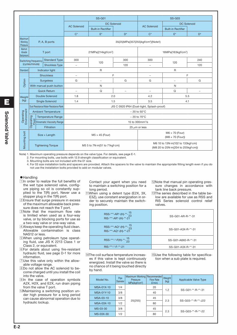
P, A, B ports 35(25)MPa{357(255)kgf/cm2}(Note1)
Maximum Allowable
BackpressureT port 21MPa{214kgf/cm2} 16MPa{163kgf/cm2}
Switching frequency(cycles/minute)
Standard Type 300120
300 300120
240
Shockless Type − 120 − 120
Standard Indicator light R R
Op
tion
Shockless − F − F
Surgeless G − G G − G
With manual push-button N N
Quick Return − Q − − Q −
Weight(kg)
Double Solenoid 1.8 2.0 4.2 5.5
Single Solenoid 1.4 1.5 3.5 4.1
Op
erat
ing
Env
iro
nmen
t
Dust Resistance/Water Resistance Rank JIS C 0920 IP64 (Dust-tight, Splash-proof)
Ambient Temperature − 20 to 50°C
Op
erat
ing
Flu
id
Temperature Range − 20 to 70°C
Kinematic Viscosity Range 15 to 300mm2/s
Filtration 25 μm or less
Mo
untin
g b
olt
Size × Length M5 × 45 (Four)M6 × 70 (Four)
(M8 × 70 (Four))
Tightening Torque M5 5 to 7N·m{51 to 71kgf·cm}M6 10 to 13N·m{102 to 133kgf·cm}
(M8 20 to 25N·m{204 to 255kgf·cm})
Note) 1. Maximum operating pressure depends on the valve type. For details, see page E-1. 2. For mounting bolts, use bolts with 12.9 strength classification or equivalent. 3. Mounting bolts are not included with the 01 size. 4. For 03 size installation bolts and spacers are provided. Attach the spacers to the valve to maintain the appropriate fitting length even if you do
not use the installation bolts provided to add on modular valves.
•HandlingzIn order to realize the full benefits of
the wet type solenoid valve, config-ure piping so oil is constantly sup-plied to the T(R) port. Never use a stopper plug in the T(R) port.
xEnsure that surge pressure in excess of the maximum allowable back pres-sure does not reach the T port.
cNote that the maximum flow rate is limited when used as a four-way valve, or by blocking ports for use as a two-way valve or one-way valve.
vAlways keep the operating fluid clean. Allowable contamination is class
NAS12 or less.bWhen using petroleum type operat-
ing fluid, use JIS K 2213 Class 1 or Class 2, or equivalent.
nFor details about using fire-resistant hydraulic fluid, see page D-1 for more information.
mUse this valve only within the allow-able voltage range.
,Do not allow the AC solenoid to be-come charged until you install the coil into the valve.
.In the case of operation symbols A2X, H2X, and E2X, run drain piping from the valve T port.
⁄0Maintaining a switching position un-der high pressure for a long period can cause abnormal operation due to hydraulic lockup.
Contact your agent when you need to maintain a switching position for a long period.
⁄1When using a detent type (E2X, 3X, E3Z), use constant energization in or-der to securely maintain the switch-ing position.
⁄2Note that manual pin operating pres-sure changes in accordance with tank line back pressure.
⁄3The series described in the table be-low are available for use as RSS and RIS Series solenoid control relief valves.
RSS-***-AR*-(H)-**- 1523
RIS-***-AR*-(H)-**-21SS-G01-AR-R-**-31
RSS-***-AQ*-(H)-**- 1523
RIS-***-AQ*-(H)-**-21SS-G01-A3X-R-**-31
RSS-***-*-F(H)-**- 1523 SS-G01-A8X0-R-**-31
RIS-***-*-F-**-21 SS-G01-A3X-R-**-31
⁄4The coil surface temperature increas-es if this valve is kept continuously energized. Install the valve so there is no chance of it being touched directly by hand.
⁄5Use the following table for specifica-tion when a sub plate is required.
Model No. Pipe Diameter
Maximum Working Pressure
MPa{kgf/cm2}
Recommended Flow Rate
(ℓ/min)
Weight (kg) Applicable Valve Type
MSA-01X-10 1/4
25{255}
201.2 SS-G01-**-R-**-31
MSA-01Y-10 3/8 40
MSA-03-10 3/8 452.3 SS-G03-**-R-**-J22
MSA-03X-10 1/2 80
MS-03-30 3/8 452.3 SS-G03-**-R-**-22
MS-03X-30 1/2 80

E-3
E
So
leno
id V
alve
•Solenoid Assembly Specifications
Sole
noid
Ty
pe
Power Supply Type
Voltage(V)
Frequency(Hz)
For SS-G01 For SS-G03Solenoid Coil
TypeDrive Current
(A)Holding Current
(A)Holding Power
(W)
AllowableVoltage Range
(V)
Solenoid Coil Type
Drive Current(A)
Holding Current(A)
Holding Power(W)
AllowableVoltage Range
(V)A
C
C1AC100
50
EDC64-C1
2.2 0.52 25 80 to 110
ECB64-C1
5.4 0.92 36.0 80 to 110
60 2.0 0.38 22 90 to 120
4.6 0.62 34.0 90 to 120
AC110 60 2.2 0.46 28 5.0 0.78 42.0
C115AC110
50
EDC64-C115
2.0 0.47 25 90 to 120
ECB64-C115
5.0 0.85 36.0 90 to 120
60 1.8 0.35 22100 to 130
4.2 0.57 34.0100 to 130
AC115 60 2.0 0.42 28 4.6 0.72 42.0
C2AC200
50
EDC64-C2
1.1 0.26 25 160 to 220
ECB64-C2
2.7 0.46 36.0 160 to 220
60 1.0 0.19 22180 to 240
2.3 0.31 34.0180 to 240
AC220 60 1.1 0.23 28 2.5 0.39 42.0
C230AC220
50
EDC64-C230
1.0 0.24 25 180 to 240
ECB64-C230
2.5 0.42 36.0 180 to 240
60 0.91 0.17 22200 to 260
2.1 0.29 34.0200 to 260
AC230 60 1.0 0.21 28 2.3 0.36 42.0
DC w
ith B
uilt-
in R
ectifi
er E1 AC100 50/60 EDC64-E1-1A 0.31 27 90 to 110 ECB64-E1 0.40 34.0 90 to 110
E115AC110
50/60 EDC64-E115-1A0.26 25
100 to 125 ECB64-E1150.33 31.0
100 to 125AC115 0.27 27 0.34 34.0
E2 AC200 50/60 EDC64-E2-1A 0.15 26 180 to 220 ECB64-E2 0.22 37.0 180 to 220
E230AC220
50/60 EDC64-E230-1A0.12 24
200 to 250 ECB64-E2300.16 30.0
200 to 250AC230 0.13 27 0.17 33.0
DC D1 DC12 EDC64-D1-1A 2.2 26 10.8 to 13.2 ECB64-D1 2.6 31.0 10.8 to 13.2
D2 DC24 EDC64-D2-1A 1.1 26 21.6 to 26.4 ECB64-D2 1.5 36.0 21.6 to 26.4
Explanation of model No.
SS – G 03 – A 3 X – * R – C2 – J22Design number 31: 01 size 22: 03 size for mounting bolt M8 J22: 03 size for mounting bolt M6
Power supply C: AC (50/60Hz) C1=AC100V C115=AC110V C2=AC200V C230=AC220V D: DC D1=DC12V D2=DC24V E: AC (Built-in rectifier; 50/60Hz) E1=AC100V E115=AC115V E2=AC200V E230=AC230V
With indicator light
Auxiliary symbol (Can be combined in alphabetic sequence.) F: Shockless type (Available with power supply D*, E) G: Surgeless type (Available with power supply C*, D*) N: With manual push-button Q: Quick return type (Available with power supply E*)
Transition Flow Path(Specify for A2X, H2X, E2X, A3X, H3X, E3X, A3Z, H3Z, E3Z, C7Y only)
Center position
Operation Method
Nominal diameter 01 size 03 size
Mounting method G: Cascade mounting
Wet type solenoid operated directional control valve
X Y ZClosed Semi-open Open
0 1 2 3 4 5
T
A B
P T
A B
P T
A B
P T
A B
P T
A B
P T
A B
P T
A B
P
6 7 8 9 1S 6S
T
A B
P T
A B
P T
A B
P T
A B
P T
A B
P
A B
P T
Note 1: P = Pressure port; A and B = Connection port to cylinder, etc.; T(R) = Connection port to tank
A H C ESpring Offset Spring Center Detent
T
A B
P
b
P
BA
T
a
T
A B
P
b a
T
A B
P
b a

E-4
B
C
E
F
G
H
I
J
K
L
M
N
O
So
leno
id V
alve
Options (Auxiliary Symbol Explanations)
Shockless Type(Auxiliary Symbol: F)
Surgeless Type(Auxiliary Symbol: G)
Switching Response CharacteristicsThe pressure waveforms for each valve in the hydraulic circuit shown below are shown at the bottom of this block.Opening and closing of a dry type valve gener-ates shock (noise) and pipe vibration due to the sudden drop or rise in pressure. With a shock-less solenoid valve, pressure fluctuation when the valve is opened or closed is smoothened, which eliminates shock (noise) and pipe vibra-tion.
The surge pressure waveforms when the DC so-lenoid valve power supply is opened and closed by a relay are shown at the bottom of this block. A built-in surge absorber element eliminates sparking and surge pressure.
Manual Button Type(Auxiliary Symbol: N)
Quick Return(Auxiliary Symbol: Q)
•HandlingzThis type is used in the case of power supply
type E* (with built-in rectifier) to shorten the spring return time. This also applies to D*.
xQuick return device is built-in to central ter-minal box.
T
A B
P
W=150kg63× 35×300
SS-G03-C5-FR-D2-J22
φ φ
Dry type Shockless type Normal form
Spark time
Surgeless time
Storage oscilloscope
Surge suppressor
DC power supply
Relay contact
R=1Ω Current
Voltage
SS-G03-***-GR-D2-J22
Model No. L S D
SS-G01AC Solenoid 133.5
7.5 30DC Solenoid 140.5
SS-G03AC Solenoid 155.5
9.5 35DC Solenoid 173.5
L
D
Push-buttonCan be locked by pressing the button and rotating 90°.
Stroke S
φ
Pow
er s
upp
ly
Rec
over
y Ti
me
Lim
iter
Circ
uit
Full
Wav
e R
ecti�
er C
ircui
t
Sur
ge a
bso
rber
Sol
enoi
d
SW

E-5
E
So
leno
id V
alve
Installation Dimension DrawingsAC SolenoidSS-G01- A**-R-C*-31SS-G01-H**-R-C*-31
Note) SS-G01-H**-R-**-31 The solenoid is on the opposite side of that shown for SOLa in the illustrations shown here.
SS-G01-C**-R-C*-31SS-G01- E**-R-C*-31
DDC Solenoid and RectifierSS-G01-A**-R-D/E*-31SS-G01-H**-R-D/E*-31SS-G01- C**-R-D/E*-31SS-G01- E **-R-D/E*-31
For sub plate SS-G01
Model No. E Weight
MSA-01X-10 1/4 1.2kg
MSA-01Y-10 3/8 1.2kg
Gasket Surface Dimensions ISO 4401-03-02-0-05 JIS B 8355 D-03-02-0-05(
SOL b SOL a
102204
10249.8
Space required for coil removal
SOL b SOL a
48.5109157.5
37.5
60.5 218
5.5φ
Space required for coil removal
T
BP
A B A
T
P
4- 7.54-Rc “E”4-M5x12
4- 9.5x1counterbore5.5hole
12.7
30.240.520
83 7.57.598
2730
5.1
25.9
313
1.7
555
7.5
7.5
70
12 0.75
11.541.5
71.5
11.5
27.5
43.5
21.5
15
.5
φ
φφ
)
26 32
122.8
P
AB
T
SOL a
SOL bIndicator light
Indicator light
Holes for temporary nameplate or customer’s nameplate mounting holes for wiring.
Recommended nameplate dimensions.Self-tapping screws for mounting; 3.5 x 10.
7.5φ
φ
SOL b
25.5
4871
.587
66
5.5
150.5102
46
48.5
37.5
φ
2 to G (Previously PF) 1/2
Manual push-button

E-6
B
C
E
F
G
H
I
J
K
L
M
N
O
So
leno
id V
alve
Installation Dimension DrawingsAC SolenoidSS-G03-A**-R-C*-J22SS-G03-H**-R-C*-J22
SS-G03-C**-R-C*-J22SS-G03- E**-R-C*-J22
DC Solenoid and RectifierSS-G03- A**-R-D*/E*-J22SS-G03-H**-R-D*/E*-J22SS-G03- C**-R-D*/E*-J22SS-G03- E **-R-D*/E*-J22
Note 1.) SS-G03-H**-R-**-J22 The solenoid is on the opposite side of that shown for SOLa in the illustrations shown here.
Note 2.) Attach the spacers to the valve, as shown in the dia-gram at right, to maintain the appropriate fitting length even if you do not use the installation bolts provided with the SS-G03.
SS-G03-**-*R-**-J22 SS-G03-**-*R-**-22
φD φ6.8 φ8.5
L 60.5 58
For sub plate SS-G03
Mounting bolt Model No. E Weight
M6MSA-03-10 3/8
2.3kgMSA-03X-10 1/2
M8MS-03-30 3/8
MS-03X-30 1/2
M6 gasket surface dimensions ISO 4401-05-04-0-05 JIS B 8355 D-05-04-0-05( )
TB
A
P
SOL.b
SOL.a
T
Holes for temporary nameplate or customer’snameplate mounting holes for wiring.
Recommended nameplate dimensionsSelf-tapping screws for mounting; 3.5 x 10.
Manual push-button
L
Wiring hole G1/2Note 2) Spacer
Indicator light
Indicator light
26 32
12
3668
.5 108.
592
70
178
93117.5 60.5
SOL. b
2.8φ
Dφ
SOL. b SOL. a
Space required for coil removal
SOL. b SOL. a
Space required for coil removal55
63
117.5 117.5235
135.5 60.5196
271
Note 2) Spacer
Note 2) Spacer
A
B
P
T
P
BAT
4- 11 holes
4-M6x12(M8x15)
4- 17.5x2 counterbore ( 17.5x10.8) 11 holes
4-Rc “E”
20.623.8
5477
93100
70 114
1.6
9.516
.64692
522
32
51630
25 35
φφφ
φ

E-7
E
So
leno
id V
alve
Wiring Diagram
SOL b SOL aCOM
SOL a
SOL b Ground terminal
Ground terminal Common terminals
Note) 1. In the case of a double solenoid valve, a common ter-minal is provided to simplify wiring. When the common terminal is not used, remove the terminal screws.
2. Use the ground terminal when grounding is required. 3. In the case of a solderless terminal, M3 screws. 4. Tighten terminal screws to a torque of 0.5 to 0.7N·m
{5.1 to 7.1kgf·cm}.
Electrical Circuit Diagram
Type Model No. Electrical Circuit
AC Solenoid SS-G01G03
-***-R-C*- 31J22
50/60Hz
COM
AC Solenoid
Surgeless TypeSS-G01
G03-***-GR-C*- 31
J22
50/60Hz
COM
Built-in Rectifier SS-G01G03
-***-R-E*- 31J22
50/60Hz
COM
DC Solenoid SS-G01G03
-***-R-D*- 31J22
±
COM
DC Solenoid
Surgeless TypeSS-G01
G03-***-GR-D*- 31
J22
±
COM
Built-in Rectifier
Quick Return TypeSS-G01
G03-***-QR-E*- 31
J22See page E-4 for more information.

E-8
B
C
E
F
G
H
I
J
K
L
M
N
O
So
leno
id V
alve
Performance Curves Hydraulic Operating Fluid Kinematic Viscosity 32mm2/s
Pressure Loss Characteristics
PumpType Flow Path P→A P→B A→T B→T P→T
SS-G01
A2X, H2X, E2X d d − − −
A3X, H3X b b b b −
E3X b b b b −
A3Z, H3Z, E3Z a a a a −
A4, H4, C4 a a a a a
A5, H5, C5, C6S b b b b −
C1, C1S b b a b −
C2 a b b b −
C6 b b a a −
C7Y f f e e c
C8 a f b e c
C9 a a b b −
PumpType Flow Path P→A P→B A→T B→T P→T
SS-G03
A2X, H2X, E2X e e − − −
A5 − c c − −
H5 c − − c −
A3X, H3X, E3X c c d d −
A3Z, H3Z a a d d −
E3Z b b a a −
C1 c c a c −
C2 a c c c −
A4, H4, C4 a a a a a
C5, C1S, C6S c c c c −
C6 c c a a −
C7Y g g g g f
C8 a g a g f
C9 a a c c −
Switching Response Time
Model No.Response Time (sec)
Measurement ConditionsSolenoid ON Spring Return
SS-G01-**-R-C*-31
SS-G01-**-(G)R-D*-31
SS-G01-**-R-E*-31
SS-G01-**-F(G)R-D*-31
SS-G01-**-FR-E*-31
0.02 to 0.03
0.03 to 0.04
0.03 to 0.04
0.07 to 0.10
0.07 to 0.10
0.02 to 0.03
0.02 to 0.04
0.07 to 0.10
0.04 to 0.07
0.10 to 0.15
14MPa{143kgf/cm2}
30ℓ/min
SS-G03-**-R-C*-J22
SS-G03-**-(G)R-D*-J22
SS-G03-**-R-E*-J22
SS-G03-**-F(G)R-D*-J22
SS-G03-**-FR-E*-J22
0.02 to 0.03
0.06 to 0.09
0.07 to 0.10
0.13 to 0.15
0.10 to 0.15
0.02 to 0.03
0.03 to 0.05
0.10 to 0.15
0.08 to 0.15
0.15 to 0.20
14MPa{143kgf/cm2}
70ℓ/min
Note) 1. The switching response time changes slightly with operating conditions (pressure, flow rate, viscosity, etc.) 2. In the case of power supply type E* (with built-in rectifier), the spring return time using Quick Return (option symbol: Q) is the same as D*.
1008060
2.0
1.6
Flow rate /min
1.2
0.8
MP
a
0.4
20 40
1.8
0
1.4
1.0
0.2
0.6
f e
c
d
b a
{kgf/cm2 }
20.4
16.3
12.2
8.2
4.1
18.4
14.3
10.2
2.0
6.1
2.2
2.4
22.4
24.5
Pre
ssur
e Lo
ss
ℓ
1.6
Flow rate /min
1.2
0.8
MP
a
0.4
200
1.4
1.0
0.2
0.6
{kgf/cm2}
40 60 80 100 120 140 160
4.1
6.1
8.2
10.2
12.2
14.3
16.3
2
g e d
fc
b
a
Pre
ssur
e Lo
ss
ℓ
E-9
E
So
leno
id V
alve
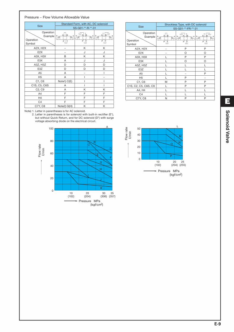
Pressure − Flow Volume Allowable Value
SizeStandard Form, with AC, DC solenoid
SS-G01-**-R-**-31
OperationExample
OperationSymbol
b a
T
B
P
A b
T
B a
P
A b
T
B a
P
A
A2X, H2X − K K
E2X − J J
A3X, H3X B K K
E3X A J J
A3Z, H3Z D D D
E3Z D D D
A5 A − I
H5 A I −
C1, C6 Note1) C(E) I I
C1S, C5, C6S A I I
C2, C9 A K K
A4 F F F
H4 F F F
C4 F F F
C7Y, C8 Note2) G(H) K K
Note) 1. Letter in parentheses is for AC solenoid. 2. Letter in parentheses is for solenoid with built-in rectifier (E*),
but without Quick Return, and for DC solenoid (D*) with surge voltage absorbing diode on the electrical circuit.
SizeShockless Type, with DC solenoid
SS-G01-**-FR-**-31
OperationExample
OperationSymbol
b
T
B a
P
A b
T
B a
P
A b
T
B a
P
A
A2X, H2X − P P
E2X − O O
A3X, H3X L P P
E3X L O O
A3Z, H3Z L L L
E3Z L L L
A5 L − P
H5 L P −
C1, C6 M P P
C1S, C2, C5, C6S, C9 L P P
A4, H4 L L L
C4 L L LC7Y, C8 N P P
I
A
BC
D
EF
G
H
J
K
P
O N
M
L50
40
30
20
10
010
{102}20
{204}25
{255}
Pressure MPa
100
80
60
40
20
010
{102}30
{306}35
{357}20
{204}
{kgf/cm
Pressure MPa{kgf/cm
ℓ/m
inFl
ow r
ate
ℓ/m
inFl
ow r
ate
2}
2}

E-10
B
C
E
F
G
H
I
J
K
L
M
N
O
So
leno
id V
alve
Pressure − Flow Volume Allowable Value
Model No.Standard Form, with AC Solenoid Standard Form, with DC Solenoid
SS-G03-**-R-C*-J22 SS-G03-**-R-**-J22
OperationExample
OperationSymbol
ab
P
BA
T T
A B
P
b a
T
A B
P
b a ab
P
BA
T T
A B
P
b a
T
A B
P
b a
A2X − F E − G H
H2X − E F − H G
E2X − C C − D D
A3X A E E A F H
H3X A E E A H F
A3Z A A C A D D
H3Z A C A A D D
E3X, E3Z A C C A D D
A5 A − D A − G
H5 A D − A G −
C1S, C5, C6S A D D A G G
C1, C6 A D D B G G
C2 A G D A I G
A4, H4, C4 A A A A A A
C9 A G G A I I
C7Y, C8 B B B Note1) C(E) C(E) C(E)
0 10{102}
20{204}
30{306}
35{357}
Flow
rat
eℓ/
min
Pressure MPa{kgf/cm2}
DG
F
20
40
60
80
100
120
140A
B
CE
Pressure MPa{kgf/cm2}
Flow
rat
eℓ/
min
160
140
35{357}
30{306}
20{204}
10{102}
0
A
60
40
120
100
80
20
HI F
E
C
G D
B
Model No.Shockless Type, with DC solenoid
SS-G03-**-FR-**-J22
OperationExample
OperationSymbol
ab
P
BA
T T
A B
P
b a
T
A B
P
b a
A2X − E F
H2X − F E
E2X − C C
A3X A D F
H3X A F D
A3Z A C C
H3Z A C C
E3X, E3Z A C C
A5 A − E
H5 A E −
C1, C1S, C5, C6, C6S A E E
C2 A G E
A4, H4, C4 A A A
C9 A G G
C7Y, C8 Note1) B(H) B(H) B(H)
F
G
D
Pressure MPa{kgf/cm2}
Flow
rat
eℓ/
min
100
25{255}
20{204}
10{102}
60
0
A120
H
B
140
80
EC40
20
Note) 1. Letter in parentheses is for solenoid with built-in rectifier (E*), but without Quick Return, and for DC solenoid (D*) with surge voltage absorbing diode on the electrical circuit.
2. There is no shockless type for the AC solenoid (C*), so use a solenoid with built-in rectifier (E*) when shockless operation is required with an AC power supply.
3. The maximum flow rate is the allowable value of each port.

E-11
E
So
leno
id V
alve
Cross-sectional DrawingsSS-G01-A**-R-C*-31
SS-G01-A**-R-D/E*-31 SS-G01-C**-R-D/E*-31
SS-G01-C**-R-C*-31
List of Sealing Parts
Part No. Part Name Part Number
Q'ty
Single Solenoid
Double Solenoid
17 O-ring AS568-012(NBR-90) 4 4
18 O-ring NBR-70-1 P20 1 2
19 O-ring NBR-90 P18 2 2
20 O-ring S-25(NBR-70-1) 1 2
Note) The materials and hardness of the O-ring conforms with JIS B2401.
Seal Kit Number
Single Solenoid Double Solenoid
EDCS-A EDCS-C
13 14 15 1620
5 2319 810 11 12 1718 6 41 7
13 14 15 1620
13459 1811 12 17 1019 7
1 4
20
618 1710 819 3
161514
2
13
12 7 511 3 1
20
19 1017
16
11 189 5
151413
4 712
Part No. Part Name
123456789
10
BodyPlugSpoolRetainer ARetainer BRetainer CSpacerSpring ASpring CNut
Part No. Part Name
11121314151617181920
RodSolenoid guideSolenoid coilPackingTerminal box kitNameplateO-ringO-ringO-ringO-ring

E-12
B
C
E
F
G
H
I
J
K
L
M
N
O
So
leno
id V
alve
Cross-sectional DrawingsSS-G03-A**-R-C*-J22
SS-G03-A**-R-D/E*-J22
SS-G03-C**-R-C*-J22
SS-G03-C**-R-D/E*-J22
List of Sealing Parts
Part No. Part Name
Type/Part Number Q'ty
AC SOL. DC SOL. Single Solenoid
Double Solenoid
17 O-ring AS568-014(NBR-90) 5 5
18 O-ring NBR-90 P28 2 2
19 O-ring NBR-70-1 P26 AS568-026(NBR-70-1) 1 2
20 O-ring AS568-029(NBR-70-1) 1 2
Note) The materials and hardness of the O-ring conforms with JIS B2401.
Seal Kit Number
AC SOL. DC SOL.
Single Solenoid Double Solenoid Single Solenoid Double Solenoid
ECBS-AA ECBS-CA ECBS-AD ECBS-CD
719118 10 7 5 3 1
1819 212 15 1620
46 11 9 178 7 4 3 1
1819 1012 15 1620
6
71418 135701
1816152019
11 9
212
6 413 14 378 911
1219 15 16 18
17
20 10
1314 6
Part No. Part Name
123456789
10111213
BodyPlugSpoolRetainerRetainer BSpacerSpringNutRodSolenoid guideSolenoid coilPacking BCoil case
Part No. Part Name
14151617181920
Coil yokeTerminal box kitNameplateO-ringO-ringO-ringO-ring