srm016-8810 modbus manual-20210506
TRANSCRIPT
Varec, Inc.5834 Peachtree Corners East, Peachtree Corners (Atlanta), GA 30092 USA
Tel: +1 (770) 447-9202 Fax: +1 (770) 662-8939
www.varec.com
SRM016-20210506
8810 Remote Terminal UnitIntelligent tank gauge with high accuracy performance
Service ManualModbus Communication Protocol

8810 RTU Modbus Manual
ii Service Manual

Varec, Inc. i
8810 RTU Modbus Manual
CopyrightAll rights reserved. Printed in the United States of America. Except as permitted under the United States Copyright Act of 1976, no part of this publication may be reproduced, stored in a retrieval system or transmitted in any form or by any means—electronic, mechanical, photocopying, recording or otherwise—without the prior written permission of the Publisher:
Varec, Inc.5834 Peachtree Corners EastPeachtree Corners (Atlanta), GA 30092USA
Trademarks acknowledgedVarec, Inc. recognizes all other trademarks. Trademarks of other products mentioned in this document are held by the companies producing them.
Varec® is a registered trademark of Varec, Inc. Copyright 2019.
VeRTUe® is a registered trademark of Varec, Inc. Copyright 2019.
Disclaimer of WarrantiesThe contract between the Seller and the Buyer states the entire obligation of the Seller. The contents of this instruction manual shall not become part of or modify any prior or existing agreement, commitment or relationship between the Seller and Buyer. There are no express or implied warranties set out in this instruction manual. The only warranties that apply are those in the existing contract between the Seller and Buyer.
This Product has not been tested by Varec under all possible operational conditions, and Varec may not have all the data relative to your application. The information in this instruction manual is not all inclusive and does not and cannot take into account all unique situations. Consequently, the user should review this product literature in view of his/her application. If you have any further questions, please contact Varec for assistance.
Limitations of Seller's LiabilityIn the event that a court holds that this instruction manual created some new warranties, Seller's liability shall be limited to repair or replacement under the standard warranty clause. In no case shall the Seller's liability exceed that stated as Limitations of Remedy in the contract between the Seller and Buyer.
Use of parts that are not manufactured or supplied by Varec voids any Varec warranty and relieves Varec of any obligation to service the product under warranty. Varec recommends the use of only Varec manufactured or supplied parts to maintain or service this product.
Terms of UseThe information provided in this document is provided "as is" without warranty of any kind. Varec, Inc. disclaim all warranties, either express or implied, including the warranties of merchantability and fitness for a particular purpose. In no event shall Varec, Inc. or its suppliers be liable for any damages whatsoever including direct, indirect, incidental, consequential, loss of business profits or special damages, even if Varec, Inc. or its suppliers have been advised of the possibility of such damages.

8810 RTU Modbus Manual
ii Service Manual
This manual is solely intended to describe product functions and should not be used for any other purpose. It is subject to change without prior notice. This manual was prepared with the highest degree of care. However, should you find any errors or have any questions, contact one of our service offices or your local sales agent.
On Safety and Proper UseRead this manual carefully and make sure you understand its contents before using this product. Follow all instructions and safety guidelines presented in this manual when using this product. If the user does not follow these instructions properly, Varec cannot guarantee the safety of the system.

Remote Terminal Unit
Varec, Inc. 1
Contents
1 Using Modbus TCP/IP . . . . . . . . . . . . . . . . . . . . . . . . . . . . . . . . . . . . . . . . . . . 3
What is Modbus TCP/IP? . . . . . . . . . . . . . . . . . . . . . . . . . . . . . . . . . . . . . . . . . . . . . 3
Modbus TCP Master . . . . . . . . . . . . . . . . . . . . . . . . . . . . . . . . . . . . . . . . . . . . . . . . . 3
Modbus TCP Slave . . . . . . . . . . . . . . . . . . . . . . . . . . . . . . . . . . . . . . . . . . . . . . . . . . 4
Gateway Blocks. . . . . . . . . . . . . . . . . . . . . . . . . . . . . . . . . . . . . . . . . . . . . . . . . 4Default Modbus Map . . . . . . . . . . . . . . . . . . . . . . . . . . . . . . . . . . . . . . . . . . . . . 5
2 Using Modbus TCP/IP . . . . . . . . . . . . . . . . . . . . . . . . . . . . . . . . . . . . . . . . . . . 7
Modbus Manager Settings . . . . . . . . . . . . . . . . . . . . . . . . . . . . . . . . . . . . . . . . . . . . 7
Inherent 8810 RTU Parameters . . . . . . . . . . . . . . . . . . . . . . . . . . . . . . . . . . . . . . . . 8
Configuration. . . . . . . . . . . . . . . . . . . . . . . . . . . . . . . . . . . . . . . . . . . . . . . . . . . 8

Contents
2 Installation and Operations Manual

Varec, Inc. 3
1 Using Modbus TCP/IP
This chapter describes how Modbus TCP works with the 8810 RTU as well as how to configure the Modbus TCP protocols to work with the 8810 RTU.
What is Modbus TCP/IP?
Modbus TCP/IP is an industry-standard data protocol that the 8810 RTU uses to communicate with remote tanks and gauges using TCP/IP.
TCP stands for Transmission Control Protocol, a data protocol that communicates information over Ethernet or across the internet. Modbus information is communicated by encapsulating the information in the TCP format and then given to IP (Internet Protocol) to place the whole package of information into a packet and then transmit it. TCP checks the information to make sure it makes sense and is configured correctly as well as received correctly while IP makes sure the packets are correctly addressed and are routed to where they need to go.
The Modbus TCP protocol communicates information in three different ways: 32-bit float, 32-bit uint, and 16-bit uint.
Float values (floating point values) are decimal-based values which are important to getting exact measurements. Uint values are unsigned integer values in a whole number format. Unsigned means it cannot be negative. The valid value range for 32-bit uint is 0 - 4,294, 967, 295, and the valid value range for 16-bit uint is 0 - 65,535. Within Modbus, the registers are 16-bit, so a 32-bit value takes two registers to hold the data.
The Modbus TCP protocol the 8810 RTU uses transmits data over IP using Ethernet. The CPU Module’s Ethernet channel (channel 2) includes both a Modbus client (commonly known as a Modbus Master) and a Modbus server (commonly known as a Modbus Slave), meaning the 8810 RTU can function as both a Modbus TCP Master and a Modbus TCP Slave.
The 8810 RTU is capable of communicating with Modbus TCP compatible devices whether the device is either a Modbus Master or Slave device. This is due to the 8810 RTU design being flexible, allowing communications with devices that comply with the Modbus TCP protocol, as well as devices that support Modbus over TCP.
There are two protocol handlers available with the 8810 RTU: The Modbus TCP Master protocol handler performs scans of Modbus Slave devices, while the Modbus TCP Slave protocol handler responds to read and write requests from a Modbus Master system. A detailed description of both the Modbus Master and Modbus Slave protocol handlers follows below.
Modbus TCP Master
The Modbus TCP Master protocol handler scans data from Modbus Slave devices. The Modbus TCP Master sends out a request for information to the other device which responds to the request. Packets include the address of the specific device the Master wants to communicate with, so that only the correct Modbus device will respond.
Data read from a remote Modbus TCP devices is copied into the Value00 to Value63 parameters of one of two point types: Modbus Floating Point Register (MFPREG) or Modbus Integer Register (MIREG). The Modbus Register Map (REGMAP) point type can then be used to transfer this data into specific parameters within the RTU (such as a Tank's 'Level' parameter.) The 8810 RTU uses Modbus Register Maps (REGMAP) to copy or "map" the value (Value00 to Value63) of a Modbus Floating Point Register (MFPREG) or a Modbus Integer Register (MIREG) to a variety of available parameters within the 8810. For example, MFPREG Value00 can be mapped to a Tank’s Level parameter, meaning that Level is updated any time Value00 is updated.

Using Modbus TCP/IP
4 Installation and Operations Manual
The user specifies data addresses and block sizes for requesting data from devices they want the Modbus TCP Master to communicate with. Points are processed sequentially and data is requested from the respective devices.
Modbus TCP Slave
The Modbus TCP Slave protocol handler responds to requests from Modbus Master devices. The Modbus Slave protocol handler is flexible, allowing the user to set options for handling several aspects of Modbus communications. Modbus TCP Slave uses the "GWBLK" (gateway block) as a lookup table for data addresses. Also see the Gateway Blocks section below for more information.
The gateway block allows the user to specify data address and point reference combinations. This allows the 8810 RTU to be used with an existing system that is already configured. The user defines a GWBLK point and specifies which parameter in the 8810 RTU will be used for a particular address.
When a request from a Modbus client is received, the Modbus TCP Slave protocol handler will search through the GWBLK points and determine if the data address of the request is specified in the GWBLK points. If the data address is contained in a GWBLK point, then the corresponding point reference is used to provide the data for the reply to the master. The 8810 RTU takes a number of gateway blocks and puts them together to create a Modbus Map which informs the 8810 RTU to understand the setup of the Modbus Slave.
A ModbusMap in Vertue is an ASCII string of 32 bytes max containing the name of the Modbus Map. A Modbus Slave channel contains one or more gateway blocks, with the ModbusMap used to match each gateway block to its Modbus Slave channel.
Multiple GWBLK can have the same ModbusMap value. Combined, these GWBLK with the same ModbusMap value form the complete Modbus Map for any Modbus Slave channel that also has that same ModbusMap value.
Gateway Blocks
The 8810 RTU includes a configuration construct referred to as a “gateway block” (GWBLK). The idea behind gateway blocks is to allow the user to assign specific Modbus addresses to an 8810 RTU’s data parameter (such as a Tank’s Level). Once a gateway block is configured and assigned to a Modbus Slave channel, a Modbus Master device can poll the 8810 RTU using that Modbus Slave channel for data specific to that Modbus address.
The 8810 RTU provides a total of 108 gateway blocks. The configuration of the first 100 are not predefined and can be configured based on the user’s specific needs. The last 8 are used for the “Default Modbus Map.” Although these last 8 gateway blocks are predefined, the user can modify their predefined configuration, if desired.
The standard Modbus protocol defines 65,535 16-bit registers, with register addresses numbered 0 to 65,535. This limits the amount of data that can be collected using a single Modbus Map. Recognizing that a user might want to collect more data than allowed by this limit, or that two different Modbus Master devices might want different data using different formats and addresses, the 8810 RTU supports multiple user-configurable Modbus Maps. To accomplish this, each gateway block has a configuration parameter referred to as ModbusMap.
A ModbusMap is an ASCII string that can be up 32 characters long. The idea behind this is that the user assigns a gateway block to a specific Modbus Map by configuring its ModbusMap to a non-null value (e.g. “Map 1”). Then, the user configures a Modbus Slave channel’s ModbusMap parameter to the exact same ASCII string. These ASCII strings must be identical (i.e., it is case sensitive). Note that when a Modbus Slave channel is first configured, it automatically populates its ModbusMap parameter to “Default Map”, which is the ASCII string corresponding to the Default Modbus Map described in the previous section.
Remote Terminal Unit
Varec, Inc. 5
This approach allows the user to reuse Modbus addresses by assigning those reused addresses to different Modbus Maps. For example, Modbus Map “Map 1” can define address 0 to be Tank 1’s Level, while Modbus Map “Map 2” can define address 0 to be Tank 400’s StrapVol. One Modbus Slave channel would use “Map 1”, while a second Modbus Slave channel would use “Map 2”.
Default Modbus Map
The user has the ability to configure up to 100 GWBLKs for the Modbus TCP Slave. In addition, the 8810 RTU comes with eight more pre-configured GWBLKs. These eight are referenced to as the "Default Modbus Map."
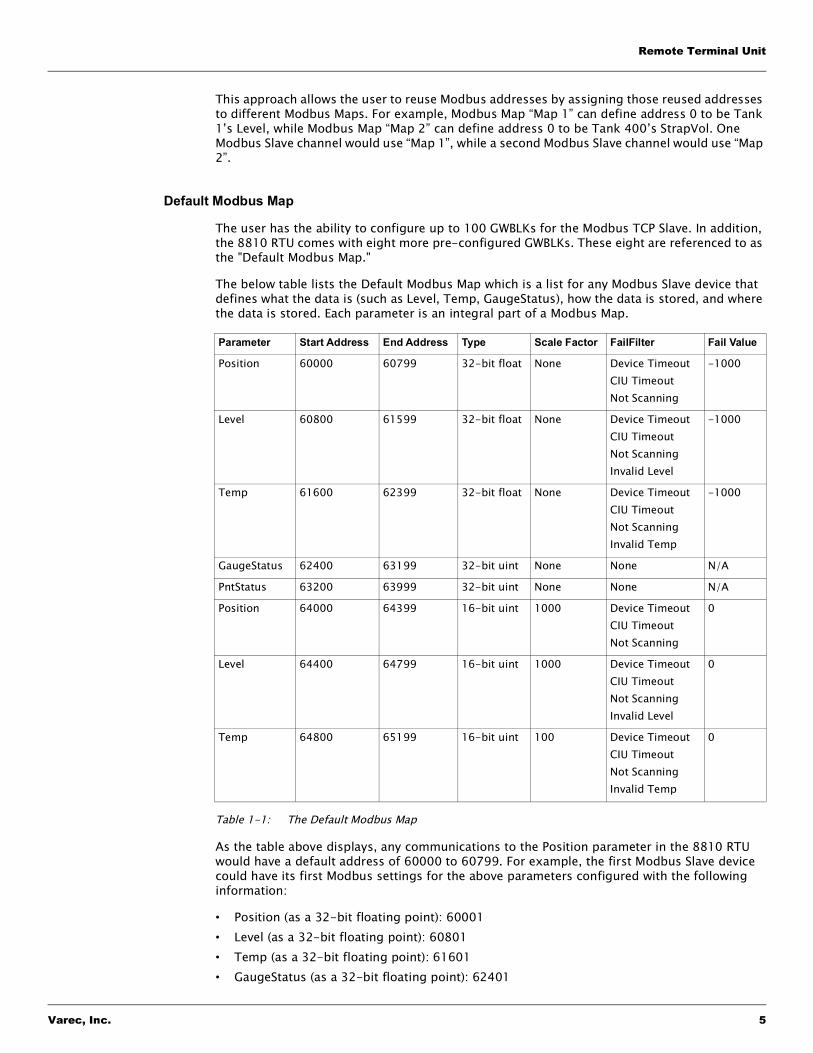
The below table lists the Default Modbus Map which is a list for any Modbus Slave device that defines what the data is (such as Level, Temp, GaugeStatus), how the data is stored, and where the data is stored. Each parameter is an integral part of a Modbus Map.
Table 1-1: The Default Modbus Map
As the table above displays, any communications to the Position parameter in the 8810 RTU would have a default address of 60000 to 60799. For example, the first Modbus Slave device could have its first Modbus settings for the above parameters configured with the following information:
• Position (as a 32-bit floating point): 60001• Level (as a 32-bit floating point): 60801• Temp (as a 32-bit floating point): 61601• GaugeStatus (as a 32-bit floating point): 62401
Parameter Start Address End Address Type Scale Factor FailFilter Fail Value
Position 60000 60799 32-bit float None Device TimeoutCIU TimeoutNot Scanning
-1000
Level 60800 61599 32-bit float None Device TimeoutCIU TimeoutNot ScanningInvalid Level
-1000
Temp 61600 62399 32-bit float None Device TimeoutCIU TimeoutNot ScanningInvalid Temp
-1000
GaugeStatus 62400 63199 32-bit uint None None N/A
PntStatus 63200 63999 32-bit uint None None N/A
Position 64000 64399 16-bit uint 1000 Device TimeoutCIU TimeoutNot Scanning
0
Level 64400 64799 16-bit uint 1000 Device TimeoutCIU TimeoutNot ScanningInvalid Level
0
Temp 64800 65199 16-bit uint 100 Device TimeoutCIU TimeoutNot ScanningInvalid Temp
0

Using Modbus TCP/IP
6 Installation and Operations Manual
• PntStatus (as a 32-bit floating point): 63201• Position (as a 16-bit unsigned integer point): 64001• Level (as a 16-bit unsigned integer point): 64401• Temp (as a 16-bit unsigned integer point): 64801
Using a different value for the ModbusMap parameter, a second Modbus Slave channel could create other GWBLKs and re-use these same Modbus addresses for a completely different set of parameters.
Note If the values of NumberOfMfpreg, NumberOfMireg, NumberOfGwblk, and Number-OfTanks add up to more than 160, the default number of points for the MFPREG, MIREG, GWBLK, and TANKA point types will be reported through the "RTU Slave" protocol.”
The 8810 RTU provides two interfaces to external clients. The first is the OPC UA server embedded within the CPU Module's Ethernet channel. This interface has no limits and the full complement of point types are available.
The second is the legacy RTU serial data protocol, which is configured by setting a channel's Protocol parameter to "RTU Slave." This serial port operates at a much slower baud rate and has severe limitations on the number and types of points that can be accessed through it. Specifically, the total number of MFPREG, MIREG, GWBLK, and TANKA points is limited to 160 in this legacy interface.

Varec, Inc. 7
2 Using Modbus TCP/IP
This brief chapter describes how to configure the Modbus TCP protocols to work with the 8810 RTU.
Modbus Manager Settings
The Modbus Manager in Vertue allows the user to configure the following register map settings.
Setting Name Definition Type Variables Choices/Defaults
Config
SrcType Source Point Type 32-bit unsigned int 3 = Port (Module & Channel)4 = Modbus Floating Point Register5 = Modbus Integer Register
SrcIndex Source Point Index. 32-bit unsigned int Valid values are 1 to 100 which corresponds to the index of the Modbus Floating Point and Integer Registers
SrcParameter Source Point Parameter 32-bit unsigned int 99 corresponds to Value00, 100 to Value01, 162 to Value63, etc.
553 corresponds to ConvertedValue
DestType Destination Point Type 32-bit unsigned int 1 = CPU Module2 = Interface Module3 = Port (Module & Channel)4 = Modbus Floating Point Register5 = Modbus Integer Register6 = Gateway Block7 = Tank8 = Alarm
DestIndex Destination Point Index 32-bit unsigned int Valid values depend upon the DestType:CPU Module (1)Interface Module (1-6)Port (1-56)Modbus Floating Point Register (1-100)Modbus Integer Register (1-100)Gateway Block (1-108)Tank (1-400)Alarm (1-1000)
DestParameter Destination Parameter 32-bit unsigned int The parameter to which the register value will be mapped.

Using Modbus TCP/IP
8 Installation and Operations Manual
Inherent 8810 RTU Parameters
The following sections describe in detail each of the listed points that are embedded in every 8810 RTU. Each section provides instructions on configuring the parameters and the applications.
Configuration
DataMode A bitmap field defining how the Modbus Integer Register source is converted to a 32-bit floating point destination.
32-bit unsigned int Bitmap field defining how the Modbus Integer Register source is converted to a 32-bit floating point destination.Scale using SrcMin, SrcMax, DestMin, DestMax parameter. Otherwise, ScaleFactor is used.0x0001 = Scale fp using Min/Max
ScaleFactor Floating point Multiply the source integer value by ScaleFactor to produce a 32-bit floating point value to be copied to the destination parameter.Defaults to 1.
SrcMin Minimum source value Floating point 0.0
SrcMax Maximum source value Floating point 0.0
DestMin Minimum destination value Floating point 0.0
DestMax Maximum destination value Floating point 0.0
Command
PntStatus Point Status 32-bit unsigned int 0x01 = Invalid source0x02 = Invalid destination
Setting Name Definition Type Variables Choices/Defaults
Parameter Type Values Factory Default Description
Label Config ASCII string Gateway Block XXX
32-character ASCII string where ‘XXX’ is the GWBLK number (001 to 108)
Address Config 0 to 65,535 0 Modbus starting address for the GWBLK
Size Config >=0 1 The number of parameters contained in the GWBLK. For example, the 8810 contains up to 400 tanks so this field would be a value from 1 to 400 for a tank.

Remote Terminal Unit
Varec, Inc. 9
Interval Config >=0 1 The number of Modbus 16-bit registers between the start of each parameter in the GWBLK. Address, Size, and Interval are used together to define the map.
For example, Address = 1000, Size = 5, and Interval = 10 results in 5 parameters at addresses 1000, 1010, 1020, 1030, and 1040. Set Interval to 0 or 1 if the parameter uses consecutive addresses.
PntType Config 1 to 8 0 The point type. Values are:• 1: CPU Module• 2: Interface Module• 3: Port (i.e. Module & Channel)• 4: Modbus Floating Point Register• 5: Modbus Integer Register• 6: Modbus Gateway Block• 7: Tank• 8: AlarmPntType, PntIndex, and PntParameter are used together to specify the parameter being assigned to the Modbus Address.
PntIndex Config >=0 0 The index into the point. The valid range depends on the point type:• CPU Module — valid range is 1• Interface Module — valid range is 1 to 6• Port — valid range is 1 to 56• Modbus Floating Point Register — valid
range is 1 to 100• Modbus Integer Register — valid range
us 1 to 100• Modbus Gateway Block — valid range is
1 to 108• Tank — valid range is 1 to 400• Alarm — valid range is 1 to 1000PntType, PntIndex, and PntParameter are used together to specify the parameter being assigned to the Modbus Address.
PntParameter Config >=0 0 Numeric value corresponding to a specific parameter within the point. Commonly used values are:• 40: PntStatus• 238: GaugeStatus• 239: Position• 240: Level• 241: TempPntType, PntIndex, and PntParameter are used together to specify the parameter being assigned to the Modbus Address.
Parameter Type Values Factory Default Description

Using Modbus TCP/IP
10 Installation and Operations Manual
ModbusMap Config ASCII string Default Map ModbusMap is a 32-character (max) ASCII string and is case-sensitive. ModbusMap is used to associate a Gateway Block with one or more Modbus Slave channels, or with the Modbus TCP port on the Ethernet channel (i.e., CPU Module Channel 2). Each of these channels has its own ModbusMap parameter, which can be set to different values. When a Modbus message is received on one of these Modbus channels, the 8810 RTU searches for Gateway Blocks with identical ModbusMap values and uses matching Gateway Blocks to respond to that Modbus message. This allows the 8810 RTU to support multiple Modbus Maps simultaneously. For example, depending on the configuration of the Gateway Blocks, one Modbus Slave channel might interpret Modbus register 100 as a “Level”, while a different Modbus Slave channel might interpret that same register as “Temp”.
DataMode Config >=0 0 Bitmap field used to configure the data mode.• 0x00000001: Convert a 32-bit floating
point number to a 16-bit integer using InputMin, InputMax, OutputMin, and OutputMax.
• 0x00000002: Convert a 32-bit floating point number to a 16-bit integer by multiplying the floating point number by ScaleFactor.
• 0x00000004: 32-bit parameter mode. When reading more than one parameter, setting this bit increments to the next (32-bit) parameter within the same point (aka parameter mode), rather than the same parameter in the next point (aka indexing mode). Typically used with Modbus Floating Point and Integer Registers.
• 0x00000008: 16-bit parameter mode. Similar to 32-bit parameter mode, but this uses only the least significant 16 bits in each 32-bit parameter. Typically used with Modbus Integer Register when the register has only 16 bits of meaningful data. This mode produces garbage if used with a floating point parameter.
• 0x00000010: Report 0xFFFF as the value if the source data is bad, instead of the value specified in the FailValue parameter. (FailFilter determines if data is bad.) Only used when a 32-bit floating point parameter is scaled to a 16-bit integer.
Parameter Type Values Factory Default Description
Remote Terminal Unit
Varec, Inc. 11
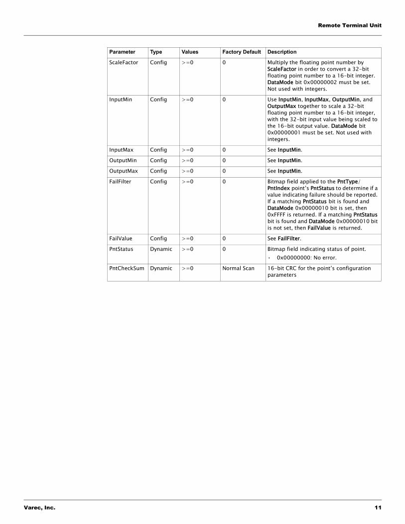
ScaleFactor Config >=0 0 Multiply the floating point number by ScaleFactor in order to convert a 32-bit floating point number to a 16-bit integer. DataMode bit 0x00000002 must be set. Not used with integers.
InputMin Config >=0 0 Use InputMin, InputMax, OutputMin, and OutputMax together to scale a 32-bit floating point number to a 16-bit integer, with the 32-bit input value being scaled to the 16-bit output value. DataMode bit 0x00000001 must be set. Not used with integers.
InputMax Config >=0 0 See InputMin.
OutputMin Config >=0 0 See InputMin.
OutputMax Config >=0 0 See InputMin.
FailFilter Config >=0 0 Bitmap field applied to the PntType/PntIndex point’s PntStatus to determine if a value indicating failure should be reported. If a matching PntStatus bit is found and DataMode 0x00000010 bit is set, then 0xFFFF is returned. If a matching PntStatus bit is found and DataMode 0x00000010 bit is not set, then FailValue is returned.
FailValue Config >=0 0 See FailFilter.
PntStatus Dynamic >=0 0 Bitmap field indicating status of point.• 0x00000000: No error.
PntCheckSum Dynamic >=0 Normal Scan 16-bit CRC for the point’s configuration parameters
Parameter Type Values Factory Default Description

Using Modbus TCP/IP
12 Installation and Operations Manual

Varec, Inc. 13
8810 RTU Modbus Manual
NOTES

Your official representative
Varec, Inc.5834 Peachtree Corners East, Peachtree Corners (Atlanta), GA 30092 USA
Tel: +1 (770) 447-9202 Fax: +1 (770) 662-8939© 2006 Varec, Inc. All Rights Reserved. This document is for information purposes only. Varec, Inc. makes no warranties, express or implied, in this summary.
The names of actual companies and products mentioned herein may be the trademarks of their respective owners.
www.varec.com
Your official representative