8800-8810 rev a - microsense
TRANSCRIPT

05/22/07
Models 8800/8810Gaging Systems
User ManualRevision A
Part Number 037893-01
Information in this document is subject to change without notice. No part of this documentmay be reproduced or transmitted in any form or by any means, electronic or mechanical, forany purpose, without the express written permission of ADE Technologies (except for copiesmade as working documents for use with ADE Technolologies-supplied equipment).
© 2007 ADE Technologies. All rights reserved.

2 - Model 8800/8810 User Manual

Model 8800/8810 User Manual - 3
Table of Contents
Revision History .......................................................................................................................... 4
1.0 Introduction ......................................................................................................................... 5
Overview ..........................................................................................................................5
Applications .....................................................................................................................5
Configuration ...................................................................................................................5
Power Requirements ......................................................................................................6
About the System's Probes ............................................................................................7
Illustration of Near, Nominal and Far Standoffs ..........................................................8
Example Outputs for Default Output Scaling ...............................................................9
Selected Measurement Concepts ................................................................................ 10
Displacement ................................................................................................................. 10
Runout ............................................................................................................................ 11
Step Height .................................................................................................................... 12
Velocity ........................................................................................................................... 12
Acceleration ................................................................................................................... 12
Setup Suggestions: Runout Measurements ............................................................... 13
Setup Suggestions: Mastering .................................................................................... 15
Setup Suggestions: A+B .............................................................................................. 17
2.0 Setup and Configuration ...................................................................................................19
Connecting to the 8810/8800 ......................................................................................... 19
Configuring System Outputs ......................................................................................... 19
Front Panels ................................................................................................................... 20
Connecting the Probes .................................................................................................. 21
Setting Tolerance Limits ............................................................................................... 21
Making Fine Adjustments to Scale Factor .................................................................. 22
Making Fine Adjustments to Output Voltage Offset ................................................... 22
Input/Output Connections.............................................................................................. 22
P24 9-Pin Connector Pinouts for 8810 ......................................................................... 23
P19 25-Pin Connector Pinouts for 8810 ....................................................................... 23
P22 96-Pin Connector Pinouts for 8800 ....................................................................... 24
External Module Calibration ........................................................................................ 25
Noise Immunity (ARTN) ................................................................................................. 25
Making Configuration Adjustments .............................................................................. 26
Getting Access to the PCB and Jumpers .................................................................... 26
Jumper Settings ............................................................................................................. 26
Drive Synchronization (Phase Locking) ................................................................ 27
Output Scaling ......................................................................................................... 28
Chassis GND............................................................................................................. 28
Location of Jumpers on PCB ................................................................................. 29

4 - Model 8800/8810 User Manual
Revision History of this Manual
rev date description of change
A 05/22/07 first release (Document Release #1784)
3.0 Calibration.......................................................................................................................... 31Procedure for Adjusting Scale Factor ......................................................................... 31Range Adjustment ......................................................................................................... 32
Appendix A: Grounding ............................................................................................................33Electrical Grounding .....................................................................................................33Target Grounding ..........................................................................................................33Chassis Grounding .......................................................................................................33
Appendix B: Models 8800 Calibration Interface .................................................................... 35Introduction .................................................................................................................... 35Calibration Methodology .............................................................................................. 35Connections ................................................................................................................... 35Protocol .......................................................................................................................... 36Wiring ............................................................................................................................. 36Grounding ...................................................................................................................... 37Pseudo Read-Back ........................................................................................................ 37Single-ended Connections ........................................................................................... 37I/O Hardware and Configuration ................................................................................. 38Preparation of the Gage Module for External Calibration ....................................... 38
Appendix C: Maintaining the R.F. Shielding of the Model 8810S....................................... 39
Outline/Dimensions of Model 4800 Gaging Module ............................................................... 41Outline/Dimensions of Model 4810 Gaging Module ............................................................... 45
Table of Contents (continued)

Model 8800/8810 User Manual - 5
OverviewADE MicroSense 8810 and 8800 capacitive gaging modules, combined with our Series2000 probes (sensors) are ideal for high resolution, non-contact linear displacementmeasurements and linear position sensing. This product family includes:
Model 8810 stand-alone gaging module, including low noise power supply
Model 8800 rack-mount gaging module, in standard 3U Eurocard format
Series 2000 Measurement Probes
ApplicationsHigh Accuracy Dimensional Measurement
Customers worldwide depend on ADE Technologies for solutions to their most demandinglinear displacement measurement applications. ADE's dimensional gaging systems, based onpatented capacitance sensing technology, are used to make very precise, high bandwidthmeasurements of precision products such as hard disk drive motors, air bearing spindles,precision X-Y stages, optical disks, automotive parts and machine tools. ADE's capacitivegages provide the highest resolution in the industry, with virtually unlimited service life.
High Resolution Linear Position Sensing
ADE capacitive gages and sensors are ideal for linear position sensing and ultra-highresolution servo system feedback. Leading equipment manufacturers around the world useADE capacitance sensors in wafer lithography systems, autofocus mechanisms,nanopositioning stages, metrology tools and flat panel display manufacturing equipment.Capacitive sensors provide sub-nanometer resolution, over short ranges, at a fraction of thecost of laser distance measuring interferometers. Our high vacuum-compatible capacitancesensors are ideal for linear position sensing in scanning electron microscope (SEM) andfocused ion beam (FIB) systems.
ConfigurationThe 8810/8800 modules are supplied from the factory with a default configuration. Anyadjustments to this configuration should be made prior to installation. The configurableitems, their default settings, and instructions to change them are described in this manual.
Introduction 1

6 - Model 8800/8810 User Manual
Power RequirementsThe 8810/8800 modules must be powered with regulated +15 VDC (+ 0.1 volts) power atits power pins as tabulated below.
Models 8810 Model 8800
+15 VDC at 0.120 Amp Max P22, pins 9A,9B or 9C P19, pins 6 or 18
Power Common (Ground) P22, pins 10A, 10B, or 10C P19, pins 5 or 17
-15 VDC at 0.120 Amp Max P22, pins 11A, 11B, or 11C P19, pins 4 or 16
NOTE: Only one connection is required for each of the above requirements.
The available pins are interconnected on the printed circuit board inside the
8810/8800.
1 Introduction

Model 8800/8810 User Manual - 7
About the System's ProbesThe patented measurement probes which are included with the 8810/8800 modules maybe selected from a vast variety of available models which vary in diameter and operatingrange.
The probes are quite rugged, but should be handled with care. Try to avoid
scratching the probe's sensor.
Each probe has been calibrated for use with a particular Gage board, and should be usedwith that Gage board for most accurate operation. Most probes have a 3-meter (10-foot)cable which connects to the Gage board.
The probes are transducers which form a capacitor with the target surface. Because thearea of the formed capacitor is constant, variations in capacitance are related tovariations in the distance between the probe and the target surface.
Note that the system does not measure the absolute distance between the probe andtarget surface, but variations from a nominal position known as the probe's Nominal
Standoff. At Near Standoff, the probe is at the smallest probe-to-target distance withinthe probe's operating range. At Far Standoff, the probe is at its largest probe-to-targetspacing. The 8810/8800 modules can be set for three different output-voltage scalings astabulated below:
±10 volt Output 0 to 10 volt ±5 volt
(default setting) output output
Near Standoff -10 volts 0 volts -5 volts
Nominal Standoff 0 volts +5 volts 0 volts
Far Standoff +10 volts +10 volts +5 volts
Introduction 1

8 - Model 8800/8810 User Manual
Figure 1: Illustration of Near, Nominal and Far Standoffs
Nominal Standoff
Near Standoff
Far Standoff
Target surface here
yields negative
displacement
Target surface here
yields positive
displacement
Probe
operating
range
1 Introduction
Model 8800/8810 User Manual - 9
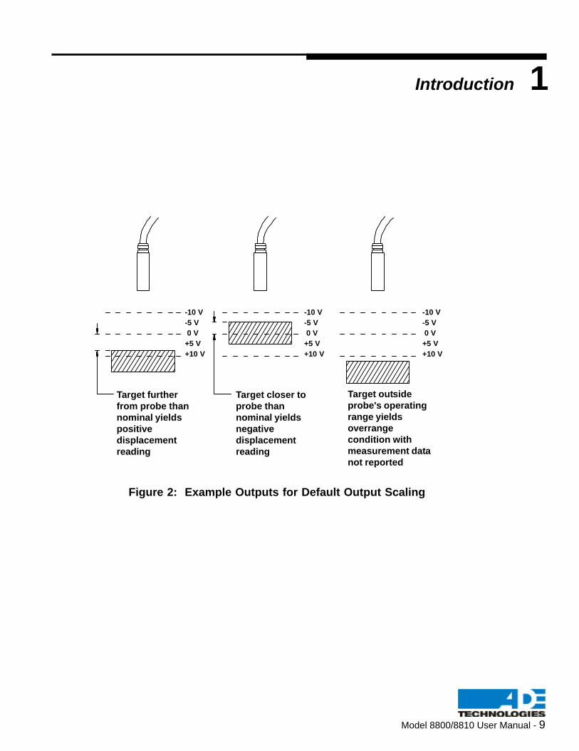
Figure 2: Example Outputs for Default Output Scaling
-10 V
-5 V
0 V
+5 V
+10 V
Target further
from probe than
nominal yields
positive
displacement
reading
Target closer to
probe than
nominal yields
negative
displacement
reading
Target outside
probe's operating
range yields
overrange
condition with
measurement data
not reported
-10 V
-5 V
0 V
+5 V
+10 V
-10 V
-5 V
0 V
+5 V
+10 V
Introduction 1

10 - Model 8800/8810 User Manual
Selected Measurement Concepts
Microsense probes measure displacement. Measurements which may be derived using the Model8810/8800 gaging systems are described briefly in the pages which follow.
Displacement"Displacement" is the distance change between the probe and a target surface.
Surface variations can be examined by measuring displacement values over the entire surface of a movingobject.
Probe Sensing Surface
Probe Sensing Surface
1 Introduction
Figure 3: Displacement Illustrations
Target
Target
Model 8800/8810 User Manual - 11
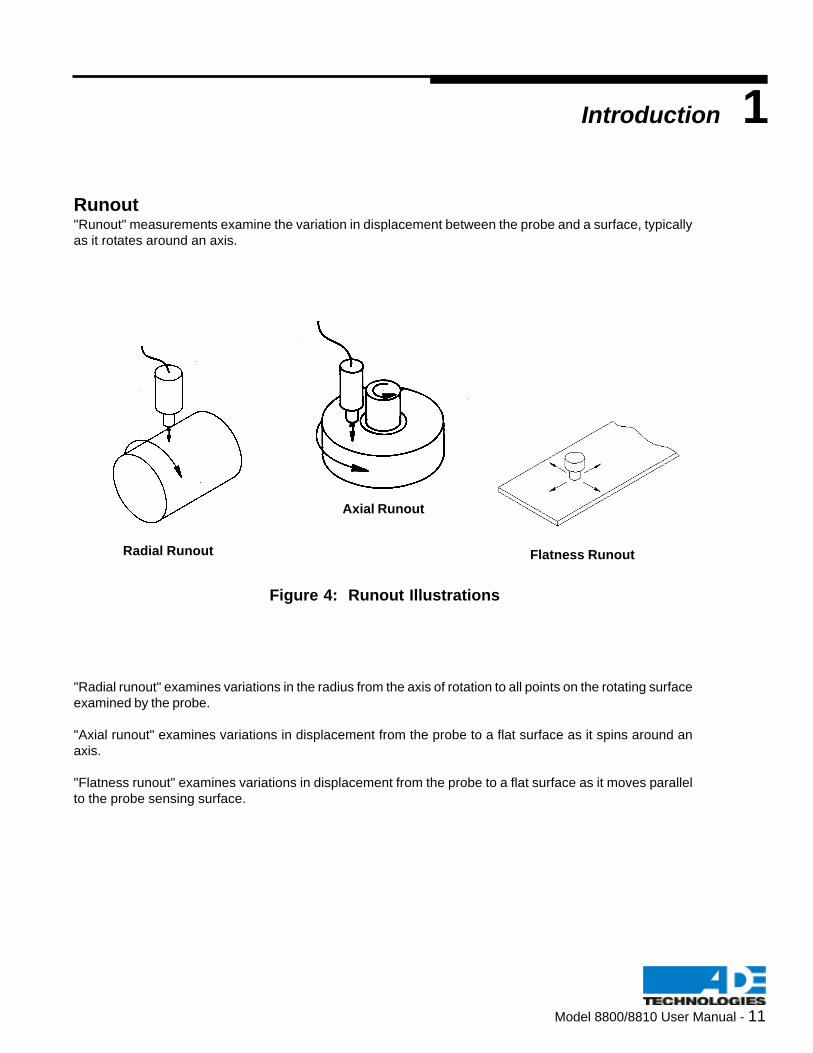
Runout"Runout" measurements examine the variation in displacement between the probe and a surface, typicallyas it rotates around an axis.
"Radial runout" examines variations in the radius from the axis of rotation to all points on the rotating surfaceexamined by the probe.
"Axial runout" examines variations in displacement from the probe to a flat surface as it spins around anaxis.
"Flatness runout" examines variations in displacement from the probe to a flat surface as it moves parallelto the probe sensing surface.
Radial Runout
Axial Runout
Flatness Runout
Introduction 1
Figure 4: Runout Illustrations

12 - Model 8800/8810 User Manual
Step Height"Step height" is an example of a two-channel measurement, where one displacement value is subtractedfrom another.
Figure 5: Step Height Illustration
Two probes can be used independently (without adding or subtracting displacement values) to analyzedisplacement in one direction with respect to displacement in another direction. This relationship may bedisplayed on an oscilloscope.
Figure 6: Displacement A & B Illustration
VelocityThe "surface velocity" of a measured object describes the rate at which the displacement measurement ischanging. This value is equal to the first derivative of displacement with respect to time.
AccelerationThe "surface acceleration" of a measured object describes the rate at which the surface velocity is chang-ing. This value is equal to the second derivative of displacement with respect to time.
Probe B Probe A
1 Introduction
Displacement A
Displacement B

Model 8800/8810 User Manual - 13
Setup Suggestions: Runout Measurements
Runout measurements examine variations in moving or rotating objects. In measurements where a largerunout is expected (close to the full range of the gage), it is important to make certain that the probe isactually in range over the entire surface to be measured before attempting dynamic measurements. Thisensures that an overrange condition will not occur even though the runout (change in displacement) doesnot exceed the range of the gage. In this case, instead of positioning the probe for a zero readout over anypoint on the surface, it may be more convenient to position the probe for an approximate full scale indicationat a known low point on the surface (such as the lobe of the cam or major diameter of an eclipse) or toposition for an approximate negative full scale reading at a known high point on the surface.
If the change in runout is measured with respect to the change in rotational speed or start up "chatter" of aspindle, the fullest dynamic range of the probe can be obtained by making a single rotation and/or a singlelongitudinal pass along the section to be measured. While doing this, observe the displacement output ofthe probe and reposition the probe to balance the positive and negative meter deflections over the surfaceto be measured. If the largest positive reading is greater than the largest negative reading, the probe is toofar and should be moved closer. If the largest negative reading is greater than the largest positive reading,the probe is too close and should be farther away.
Introduction 1

14 - Model 8800/8810 User Manual
1 Introduction
O/R
Meter
Range Meter
Range
O/R
Meter
Range
Meter
Range
(a) (b)
(c) (d)
The figure shown below illustrates the effects of the datum reference determined by probe position onrunout measurements. When the probe is too far from the examined surface (a), an overrange conditionmay result for negative peaks. Similarly, when the probe is too close to the examined surface (b), anoverrange condition may result for positive peaks. The probe should be placed so that the nominal readingis halfway between the two peaks (c), to allow all measured points on the moving surface to be in range.Selecting a good datum reference allows "exaggerated" peaks due to axis movement, vibration, or startupchatter to also remain in range (d).
Figure 7: Runout Measurements

Model 8800/8810 User Manual - 15
Setup Suggestions: MasteringThe Model 8810/8800 gaging modules are not limited only to measuring displacement variations andcomparing two displacement measurements to each other. The modules can also be used for "mastering",which allows measurements to take on absolute, rather than relative, values. When a reference surface ispositioned at a known distance from the gaging reference surface or from the probe, measurements areexpressed as a value relative to this known ("master") displacement. The height of the surface from thegaging surface is then the sum of the master height and the value displayed on the meter. The probe-to-surface distance is obtained by subtracting the system output from the displacement to the master surface.
In the figure shown below, the system is set up to provide a zero reading for the displacement to the masterpart (Figure a). When the master part is replaced by a sample part (Figure b), the meter indicates a slightlynegative value. The height of the sample surface from the gaging surface is the sum of the known masterheight and this negative value, or less than that of the known master height.
Nominal Standoff
Near Standoff
Far Standoff
Master
(a)
Reference Surface
Introduction 1
Figure 8: Zero Reading with Master

16 - Model 8800/8810 User Manual
1 Introduction
Nominal Standoff
Near Standoff
Far Standoff
Sample
(b)
Reference Surface
Figure 9: Negative Reading with Sample

Model 8800/8810 User Manual - 17
(a) (b)
(c)
Setup Suggestions: A+BThickness measurements provide data for a wide variety of applications, as shown in the illustration below.Thickness can be measured at one point of a stationary part (a), at many points of a moving part (b), or atmany points of a rotating part (c).
Positioning two probes facing toward each other allows space measurements between two surfaces.Concentricity is examined by measuring the spacing between circular parts.
Introduction 1
Figure 10: A+B Thickness Measurement Applications

18 - Model 8800/8810 User Manual
1 Introduction
Notes:

Model 8800/8810 User Manual - 19
Connecting To The 8810/8800The modules' connection scheme has been designed to be simple and flexible. The 8810/8800 modules can be used as a single stand-alone gage or used in an application requiringseveral channels. When multiple units are required, the systems should be connectedtogether (synchronized).
When the 8810/8800 module is used as a single-channel gage, power is supplied on thedesignated pins described below.
Refer to Figure 11 for locations of front panel indicator lights, probe and output connectors.
Configuring System OutputsRefer to pinout charts in Section 2 of this manual.
+ ANALOG OUT: This output is the standard analog output. Voltageincreases with distance. At Near displacement, thevoltage will be negative and will increase with increasingdistance. This voltage is relative to analog ground.
- ANALOG OUT: Voltage decreases with distance. At Near displacement,the voltage will be positive and will decrease withincreasing distance. This voltage is relative to analogground.
FAR LIMIT This output is TTL low when the corresponding frontpanel LED is lit, and TTL high when the LED is off.
NEAR LIMIT: This output is TTL low when the corresponding frontpanel LED is lit, and TTL high when the LED is off.
Setup & Configuration 2

20 - Model 8800/8810 User Manual
2 Setup & Configuration
Figure 11: Front Panels of Rackmount (Model 8800) and Stand-Alone
(Model 8810) Gages
Near Limit LED
Far Limit LED
Zero Control
Scale-Factor ControlNear Limit ControlFar Limit Control
FARNR
4810
SFZ FARNR
PROBE
4800
NRLIM
FRLIM
ZERO
SF
NR
FRLIM
LIM
OUTPUT
8810
8800

Model 8800/8810 User Manual - 21
Setting Tolerance LimitsTwo limit adjustments are supplied to indicate a gage reading outside of an expected value.The limits may be set to any point in the gage’s operating range (+10 Volts).
The FAR LIMIT LED lights when the probe-to-target distance is greater than its setpoint.
The NEAR LIMIT LED lights when the probe-to-target distance is less than its setpoint.
The limit outputs on connector P22 or P24 are TTL low (less than 0.8 VDC) when theLED is lit and TTL high (greater than 3.5 VDC) when the LED is off.
Default Limit Configuration:
The limits are factory-set at the end of the probe range. The FAR LIMIT trips when thegage output (+ANALOG OUT) is greater than 10.00 volts. The NEAR LIMIT trips when thegage output is less than -10.00 volts.
To set the tolerance limits:
Two limit potentiometers are available for setting trip points of the NEAR and FAR limitlines and LEDs. These are located on the front panel on the gaging modules. Both limitpots may be set anywhere in the range of the probe. The limits are set by adjusting theprobe-to-target distance until the trip point voltage is obtained. The limit pot is then turnedso that the trip point equals the probe voltage. This is defined as the point at which theLED changes state (ON to OFF or vice versa).
Setup & Configuration 2
Connecting the ProbesConnect the probe to the 8810/8800 gaging module at the front panel connector. Usecare when handling probes and cables. DO NOT PULL ON THE PROBE CABLE(S).
The probe cable and its connectors must not be cut, spliced, or disassembled.
NOTE: The target MUST be at the same potential as analog ground. The
housing of most models of probes are grounded via the probe cable. In
most cases, electrically attaching the target to the probe shell will result
in a well grounded target.
See Appendix A for more information on grounding.

22 - Model 8800/8810 User Manual
2 Setup & Configuration
Making Fine Adjustments to Scale FactorA scale factor adjustment is available on the front panel. This potentiometer, marked "SF",allows for fine adjustments to the probe scale factor for periodic calibration. The scalefactor is the displacement-to-voltage ratio. Refer to the "Calibration" section of this manualfor more details.
NOTE: Calibration is done at the factory and should usually not need to be adjusted.
Making Fine Adjustments to Output Voltage OffsetA front panel potentiometer, marked "ZERO" (or "Z"), is provided to allow fine adjustments ofthe output voltage offset to obtain a zero reading without having to move the probe or target.The allowable range is +10% of the full scale operating range.
NOTE: Adjusting the Zero pot has no effect on the Scale Factor.
Input/Output ConnectionsThe 8810/8810 gaging modules have three input/output connections to be aware of:
P24 and P19 (for the Model 8810 module) and P22 (for the Model 8800 module).
P24 is a 9-pin female “D” subminiature connector.
P19 is a 25-pin male “D” subminiature connector.
P22 is a 96-pin male "DIN 41612" connector.

Model 8800/8810 User Manual - 23
The connectors have the following pinouts:
P24 9-Pin Connector (on the Model 8810 Gaging Module)
1 Target Connection to probe target if required
2 Near Limit TTL output, low = limit asserted
3,7,8 Agnd Ground reference for output signals
4 +Aout Analog output as defined in section 1.3
5 Artn External output ground input (see text)
6 Far Limit TTL output, low = limit asserted
9 -Aout Inverted Analog output
P19 25-Pin Connector (on the Model 8810 Gaging Module)
1 Exc Off 2.5 ma from +Exc Off to -Exc off turns off probe excitation
2 +Exc Off
3 n.c.
4,16 -15 -15 VDC “0.1V @ 0.120 A max
5,17 Com Power common (ground)
6,18 +15 +15 VDC “0.1V @ 0.120 A max
7 -Phase Board synchronization signal
8 +Phase Board synchronization signal
9 +5 Out +5 VDC Out @ 10 ma (not normally used)
10 +Load In Calibration load signal
11 -Data In Calibration data in
12 +Clk In Calibration clk in
13 +Data Out Calibration data out
14,15 n.c.
19 Dig Gnd Calibration ground (not normally used)
20 +Pclock Board synchronization signal
21 -Pclock Board synchronization signal
22 -Load In Calibration load signal
23 +Data In Calibration data in
24 -Data Out Calibration data out
25 -Clk In Calibration clk in
Setup & Configuration 2
24 - Model 8800/8810 User Manual
2 Setup & Configuration
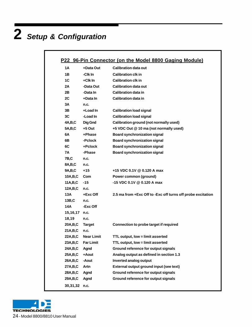
P22 96-Pin Connector (on the Model 8800 Gaging Module)
1A +Data Out Calibration data out
1B -Clk In Calibration clk in
1C +Clk In Calibration clk in
2A -Data Out Calibration data out
2B -Data In Calibration data in
2C +Data In Calibration data in
3A n.c.
3B +Load In Calibration load signal
3C -Load In Calibration load signal
4A,B,C Dig Gnd Calibration ground (not normally used)
5A,B,C +5 Out +5 VDC Out @ 10 ma (not normally used)
6A +Phase Board synchronization signal
6B -Pclock Board synchronization signal
6C +Pclock Board synchronization signal
7A -Phase Board synchronization signal
7B,C n.c.
8A,B,C n.c.
9A,B,C +15 +15 VDC 0.1V @ 0.120 A max
10A,B,C Com Power common (ground)
11A,B,C -15 -15 VDC 0.1V @ 0.120 A max
12A,B,C n.c.
13A +Exc Off 2.5 ma from +Exc Off to -Exc off turns off probe excitation
13B,C n.c.
14A -Exc Off
15,16,17 n.c.
18,19 n.c.
20A,B,C Target Connection to probe target if required
21A,B,C n.c.
22A,B,C Near Limit TTL output, low = limit asserted
23A,B,C Far Limit TTL output, low = limit asserted
24A,B,C Agnd Ground reference for output signals
25A,B,C +Aout Analog output as defined in section 1.3
26A,B,C -Aout Inverted analog output
27A,B,C Artn External output ground input (see text)
28A,B,C Agnd Ground reference for output signals
29A,B,C Agnd Ground reference for output signals
30,31,32 n.c.

Model 8800/8810 User Manual - 25
External Module CalibrationNormally, the module calibration is factory set. However, the Model 8810/8800 gaging modulesallow the calibration, which consists of a scale-factor and linearity setting, to be downloaded to themodule at power-up. For instructions on using this feature, refer to Appendix B.
Noise Immunity (ARTN)
Pin 5 of P24 Connector (Model 8810 module)
Pin 27A,B,C of P22 Connector (Model 8800 module)
The ARTN connection may be used to reduce noise due to non-uniform grounds betweenthe 8810/8800 modules and any data collection equipment. ARTN is a separate returnwhich allows external equipment to float +0.1v from analog ground. This allows the creationof a “pseudodifferential” connection to external monitoring equipment to prevent groundloops. See Appendix A for more information on grounding.
Setup & Configuration 2

26 - Model 8800/8810 User Manual
2 Setup & Configuration
Jumper Settings (Defaults are starred *)
Bandwidth The 8810/8800 modules may be set to one of four bandwidths. Use thefollowing table to determine the jumper settings:
Bandwidth P10 P11 P12 P13 P30
10 Hz N Y N Y Y100 Hz Y Y Y Y Y 1 kHz * N N N N Y10 kHz Y N Y N N
*default setting
Making Configuration AdjustmentsThe Model 8810/8800 modules include features which enable you to adjust electricalparameters of the internal printed circuit board to suit your application. These parametersare listed below, along with the default settings set at the factory.
Configurable Function Default Configuration (if applicable)
Master/Slave: Master (Single unit operation)Drive Phase: 0 DegreesOutput Scaling: +10 volts for probe rangeBandwidth: 1 kHzChassis GND Enable: Grounded (See Appendix A)Gain Setting: Adjusted at factoryLinearity Setting: Adjusted at factoryFront End Gain: Adjusted at factory
NOTE: Probe range is a function of the last three items listed above. These
jumpers are set at the factory for a specific range. Refer to the data sheet
which was included with your unit. Please contact ADE Technologies for
more information.
Descriptions of individual parameters follow. If any configurable items need to bechanged, refer to Figure 12 to locate the position of the jumpers on the PCB.
Getting Access to the Printed Circuit Board and JumpersFor the Model 8810, remove the four screws that attach the rear panel to the chassis.For the Model 8800, remove the four screws that hold the cover on (two at the DIN connectorand two along the sides).

Model 8800/8810 User Manual - 27
Drive Synchronization (Phase Locking)
When two or more Model 8810/8800 gaging modules are used to look at the same target, it isusually advisable to phase lock the excitation to the probes–especially if the target is not wellgrounded. To do this, the board synchronization signals must be bussed across all modules.So, all +Phase signals are connected together, all -Phase signals are connected together, all+Pclock signals are connected together, and all -Pclock signals are connected together.
Drive synchronization is a method of phase locking the probe drives of two or more units toprevent any probe-to-probe interactions. When more than one unit is used (one master unit withseveral slave units), the phase of the probe drives may be set to an appropriate angle withrespect to the master. This patented feature allows for the gaging of poorly grounded targetsusing two or more probes. Refer to Figure 13 for an illustration of the electrical connections formultiple units.
Configuration P2
Master * NSlave Y
*default setting
NOTE: A slave will not operate without the master unit connected and powered.
Setup & Configuration 2
To choose the proper phase angle, determine the phase angle spacing P by dividing 360 bythe number of probes that are gaging the same target. The first probe should have aphase of 0. The second probe should have a phase as close to 2P as possible. The thirdprobe’s phase should be as close to 3P as possible, etc. Here are some examples.
1. If all probes are independent, a phase angle of zero is recommended on all boards (default setting).
2. If two probes are used, the first board should be set to 0 and the second set to 180.
3. If three probes are used, the first board should be set to 0, the second set to 120, and thethird set to 240.
4. If four probes are used, the first board should be set to 0, the second set to 180, the thirdset to 0, and the fourth set to 180.
5. If five probes are used, the boards should be set to 0, 72, 144, 216 and 288 respectively.NOTE: The master must be set to 0 degrees.
The chart below shows the jumper configurations for different phase angles.
Phase P26 P27 P28
0* N N N180 Y N N120 N Y N240 N N Y 72 Y Y N144 N Y Y216 Y N Y288 Y Y Y *default setting

28 - Model 8800/8810 User Manual
2 Setup & Configuration
Output Scaling The analog output level of the Model 8810/8800 gaging modules isconfigurable. The standard output is +10 volts for the entire probe range.Shown is a table of other common output voltages that are available.(W1 - W5 set the scale factor while W10 is an offset jumper forconfiguration of bipolar/unipolar output.)
Configuration. P6 P8 P9
+10 V (Bipolar) * Y N N+5 V (Bipolar) Y Y N0 to 10 V (Unipolar) Y Y Y
*default setting
NOTE: The voltage on -ANALOG OUT will be the negative of +ANALOG OUT. If you
want a negative unipolar output, set up the jumpers as in case 3 above and
use the -ANALOG OUT output. This will give you a 0 to -10 V swing.
Chassis GND A jumper has been provided allowing the chassis of the Model 8810/ 8800gaging modules to be either grounded or ungrounded. See Appendix A formore grounding information.
Configuration P3
Chassis Grounded * YChassis Ungrounded N
*default setting

Model 8800/8810 User Manual - 29
Setup & Configuration 2
Figure 12: Location of Jumpers on PCB
Chassis Ground
P3
P30
FilterOutput Scaling
P6 P8
Zero
Enable
Bipolar Out
P29
P9
P7
Test
Phase
P28
P27
P26
Slave
P2
P19 (4805/8810)
P24 (4805/8810)
P22 (8800)
AC Gain
P5 P4
Linearity Controls
Scale Factor Controls
Compensation
P15 P16
MSD LSD
SW6 SW7 SW8
MSD LSD
SW1 SW2 SW3
Filter
P11
P10 P12
P13
Ref Cap Select
P17
P18
P25
P21
Lin RangeTarget
P14
Default Control Settings:
Function Setting Control Position
Master/Slave Master P2 outPhase 0 degrees P26, P27, P28 outOutput scaling +10 Volts P6 in, P8, P9 outFilter 1 kHz P10, P11, P12, P13 out, P30 inZero Enabled P29 inChassis Gnd Connected P3 inCompensation Set at CalibrationScale Factor Set at CalibrationTarget Grounded P14 lowerLin Range Factory Set P25 outAC Gain Factory Set P5 in, P4 out

30 - Model 8800/8810 User Manual
2 Setup & Configuration
Figure 13: Electrical Connections for Multiple 8810 Units in
Synchronization (As Shown from the Rear)
Wires should be connected from pins 7, 8, 20 and 21 of the "P2" connector
on the rear panel of each unit.
Model 8810
"P2" 25-pin connector
Model 8810
"P2" 25-pin connector Model 8810
"P2" 25-pin connector

Model 8800/8810 User Manual - 31
Procedure for Adjusting Scale FactorThe Model 8810/8800 gaging modules’ scale factor may be adjusted via a front panelpotentiometer. This pot is labeled "SF" on the front panels of the Models 8810/8800 units.
The following procedure should be followed to adjust the scale factor:
Equipment Needed:
1. Digital Volt Meter with +10 Volt range2. Fixturing equipment capable of moving the target precisely throughout the
measurement range3. Small screwdriver to access the front panel scale factor potentiometer
NOTE: Calibration is very dependent on fixturing. It is important that the
probe and target be parallel or calibration errors will occur.
Procedure:
1. Set the probe at near standoff so that the DVM reads -10.000 volts on +ANALOGOUT output.
2. Move the probe or target so that the gap between them increases by the totalmeasurement range (i.e., for a +100 um range, increase by 200um). Measureaccording to the fixturing equipment.
3. Note this voltage.
4. Adjust the pot so that the reading on the DVM (+ANALOG OUT) is:
10 + [ (10 - [reading in step 3]) / 2 ]
Example:If step 3 reading = 9.900 V, adjust pot so that DVM reads 10.050 V.If step 3 reading = 10.150 V, adjust pot so that DVM reads 9.925 V.
5. Repeat steps 1-4 to check the calibration adjustment. The procedure is completewhen the reading is within a desired tolerance. Iteration may be necessary toprecisely adjust the scale factor.
The scale factor may be adjusted to better than 10 mV.
Calibration 3

32 - Model 8800/8810 User Manual
Range AdjustmentThe Model 8810/8800 gaging modules incorporate a flexible architecture which permits youto perform a full calibration of the system. This will allow you to install a new probe orchange ranges as needed.
The range adjustment feature requires specialized fixturing and is usually done at thefactory. A description of this feature has not been included in this manual. Please contactADE Technologies Technical Support for further information.
3 Calibration

Model 8800/8810 User Manual - 33
Electrical GroundingElectrical grounding issues are important to capacitive gaging. This type of transductiongenerally requires that the target be connected to the circuit ground of the Model 8810/8800gaging modules.
Target GroundingThe target must be connected to the circuit ground of the gaging system. The Model 8810/8800 gaging modules have been designed so that the probe housing is grounded. Anelectrical connection from the probe shell (or the fixture holding the probe) to the target willprovide the necessary ground. If this is not possible, a wire may be run from the Model8810/8800 gaging modules directly to the target.
Chassis GroundingA jumper has been provided (P3) which will explicitly ground the chassis. The defaultconfiguration is with the jumper in place. This will connect the case to ground directly.
For some applications, it may be desirable to remove this jumper to improve noiseperformance or remove ground loops caused by the fixtured position of the Model 8810/8800gaging modules.
Appendix A
Grounding

34 - Model 8800/8810 User Manual
Notes:
A Appendix

Model 8800/8810 User Manual - 35
Appendix B
Models 4800/5800/8800 Calibration Interface
IntroductionThe 4800, 4810, 5800, 5810, 8800, and 8810 are provided with a calibration interface for thosecustomers who wish to download calibration information from a system controller to their ADEgage modules. The interface uses serial, differential connections and a simple protocol. Anynumber of modules can be daisy chained, which elminates the problem of increasing the complex-ity of the interface as the number of modules to be calibrated increases.
Calibration MethodologyBoth the 48XX, 58XX and 88XX gage modules require two calibration constants, one for settingthe scale factor, and one for adjusting the linearity. These constants are stored as two 12-bitbinary numbers by setting six hex switches located on the PC board. However, the outputs ofthese switches are wired-ored with the output from a 24-bit shift register. So, if all the outputs ofthe hex switches are set to be open, the shift register can control the calibration settings. It is thisshift register, along with additional circuitry, that implements the remote calibration interface.
ConnectionsAll connections for the calibration interface are provided at the rear-panel connector(s). Thepinouts are as follows:
Signal: Pin: 4800, 5800, 8800 Pin: 4810, 5810, 8810
(96-pin male DIN 41612) (25-pin male DSUB)
+Data Out 1A 13
-Data Out 2A 24
+Data In 2C 23
-Data In 2B 11
+Clock In 1C 12
-Clock In 1B 25
+Cal Enable 3B 10
-Cal Enable 3C 22
+5 VDC 5A,B,C 9
GND 4A,B,C 19

36 - Model 8800/8810 User Manual
B Appendix
ProtocolThe serial data to be downloaded to the gage module is clocked into the shift register on therising edge of the clock. The Cal Enable signal determines whether or not the shift register’soutput is tri-stated or presented to the gage board.
The order of the shifted data is as follows: MSB of the scale-factor word first, and LSB of thelinearity word last, so:
LIN0, LIN1, LIN2…SF0, SF1, SF2…SF11
An example data stream would look like:
WiringThe calibration interface can be configured as either a two-wire or three-wire interface. A typicalthree-wire scheme is shown below.
System Controller
48XX/58XX 48XX/58XX
Dat In Dat Out Dat In Dat Out
Clock ClockCal En Cal En
Note that although one clock, and one data signal is shown in the example above, theselines are differential, so each signal comprises two connections. Note also that the
calibration information is not stored in non-volatile memory, and therefore, it must
be downloaded to the board on power-up.
Figure 13: Example of a Data Stream
Figure 14: A Typical Three-Wire Interface
48XX/58XX/88XX 48XX/58XX/88XX

Model 8800/8810 User Manual - 37
Although the Cal Enable is used in the above example, in most cases it will not be required.When not used, the +Cal Enable line can be tied to the GND connection of the 48XX/58XX/88XX output connector, and the –Cal Enable line can be tied to +5 VDC pin of the outputconnector. These connections will enable the remote interface. In general, the Cal Enablesignal will only be required if it is necessary to avoid the module outputs from changing withevery clock pulse during the time new calibration data is downloaded.
GroundingThe differential connections provide two distinct advantages, 1) they offer highly reliable datatransfer, and 2) they eliminate potential ground loops between the gage modules and thesystem controller. If the gage’s power supply is referenced to ground along with the systemcontroller, there should be no need for a ground connection between the gage modules andthe system controller. If the gage modules are not referenced to ground, a ground connectionbetween the modules and system controller is necessary.
Pseudo Read-backAlthough a true data read-back feature is not implemented in this interface, a pseudo read-back can be easily implemented by connecting the data output lines from the last gage boardin the daisy chain back to an input of the system controller. To read the existing calibrationdata stored in the modules, simply issue n*24 clock pulses, where n is the number ofmodules. The data stream that comes back to the system controller is the calibration datathat was stored in the modules. The data can then be downloaded back to the modules torestore the values.
To verify proper data transmission whenever loading new data to the modules, simplyconcatenate two complete data sets. The first data set will be clocked through the modulesand returned to the system controller, and the second data set will remain in the modules.
Single-ended connectionsIf a short connection between the system controller and modules is used, and ground loopsare not a problem, single-ended communications can be implemented by tying either the +or – input of the signal in question to about 1.5 volts for TTL-compatible outputs, or 2.5volts for CMOS compatible outputs. This may be readily accomplished by using a resistorvoltage divider from the input in question to +5 VDC and ground. Because the modules’calibration inputs are CMOS, resistor values need not be low. For example, a 10k resistorto +5 and a 4.7k resistor to ground would be fine for TTL-compatible outputs. For extranoise immunity, connect a 0.1 ìF cap from the input to ground.
Appendix B

38 - Model 8800/8810 User Manual
47k
VCC
47k
Preparation of the Gage Module for External CalibrationIn order to use the external calibration feature, the hex switches on the gage module mustbe properly set. If the modules have been previously calibrated, it might be useful to recordthe settings of the hex switches before proceeding.
• For the 4800, 4810, 8800 and 8810: Set SW6, SW6, and SW8 to 0s, and set SW1, SW2, and SW3 to Fs.
• For the 5800 and 5810: Set SW2 through SW7 to Fs.
I/O Hardware and ConfigurationThe differential calibration inputs and outputs are provided by Linear Technology LTC1690ICs. These devices provide a ±7 V common-mode range, and are protected from ±15 kVESD discharges (human body model). For complete specs, visit the Linear Technologywebsite (www.linear.com).
All inputs have resistors to +5 VDC and ground installed on the gage module as shown belowto ensure proper operating state when the external calibration feature is not used.
B Appendix
Figure 15: Resistors and Ground

Model 8800/8810 User Manual - 39
Appendix CMaintaining the R.F. Shielding
of the Model 8810S
IntroductionThe Model 8810S has various shielding elements designed to substantially reduce effectsfrom R.F. interference. In order to maintain the effectiveness of this shielding, care must beused in connecting external signals to the 8810S module– external wires, if not properlyshielded and terminated, form an easy path for R.F. to enter.
In general all connections to the module should be made with shielded wire. It is importantfor the shield to connect directly to the conductive shell of the connector. To providebroadband shielding, the shield, typically braided wire, should not be connected via a pigtail,but should directly contact the connector shell. Specific instructions are outlined below.For various technical reasons the connectors supplied with the 8810S are not filtered, soproper shielding is crucial.
Front-Panel BNC ConnectorThis connector, which provides access to the analog output of the module, is easily shieldedby use of a standard coaxial cable. Because BNC connectors are designed for R.F. signals,virtually all BNC connectors provide proper shield termination. If, however, the device towhich this signal is connected is not itself properly shielded, R.F. can gain an entry point viathe center conductor of this cable.
Should this occur, solder a 1 nF capacitor directly across the BNC terminals where theyenter the offending equipment. Be sure that the capacitor is placed in immediate contactwith the connector’s terminals and use the absolute minimum lead length on the capacitor.To provide additional shielding, a 100-ohm to 1-kohm resistor can be placed in series withthe lead that connects to the center conductor of this same BNC connector. Place theresistor as close as possible to the BNC connector in question.
Rear-Panel 9-Pin DSUB ConnectorFollow all instructions listed above for the front-panel BNC connector. Use the suppliedmetallized backshell to shield any connections to this connector, and to terminate the braidof the shielded wire. To properly connect the braid to the backshell, first select whicheverrubber grommet best fits your cable. The cable should go through the grommet, and thebraid should be expanded and then folded back over the grommet so that when the backshellhalves are screwed together, the braid will be squished between the grommet and thebackshell.

40 - Model 8800/8810 User Manual
Rear-Panel 25-Pin DSUB ConnectorThis connector is used to supply power to the module and to sync multiple modules togetherto provide a known phase relationship between them. The power-supply connections to thisconnector have been bypassed at the connector and no further shielding of them should benecessary. Wires used for syncing should be shielded and the braid of the shielded wiremust be terminated as described for the 9-pin connector. Please note that the rubbergrommets supplied with the connector can be easily split to go around existing wires byusing a single-edged razor blade or the like to cut through the grommet in one place. As anexample, this procedure was used for the power-supply cable.

Model 8800/8810 User Manual - 41
Ou
tlin
e o
f M
od
el
8810
Fro
nt
Vie
wS
ide
Vie
w
Rear
Vie
w

42 - Model 8800/8810 User Manual
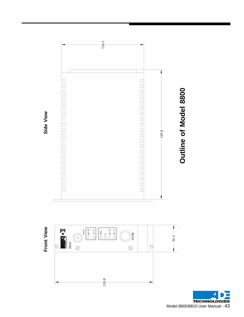
Model 8800/8810 User Manual - 43
Fro
nt
Vie
wS
ide
Vie
w
Ou
tlin
e o
f M
od
el
8800

44 - Model 8800/8810 User Manual