sr motor design with reduced torque ripple - rocky mountain
TRANSCRIPT

SR Motor Design with Reduced Torque Ripple
George H. Holling

Overview
• Motivation• Review of SRM Theory of Operation
– Theory of Operation– Mathematical Analysis– Definition of the SRM’s “Base Speed”– SRM’s Torque Ripple and Performance
• Optimization of the Conventional SRM• New SRM Geometry
– Torque Ripple and Performance– Physical Airgap and Acoustic Noise
• Outlook

Theory of Operation
SRM - Theory of Operation
• Characteristics of the SRM:
– the SRM is a “constant power” machine • similar to a series wound motor
– it is well suited to operate efficiently over a wide speed range and at very high speeds
• does not require sinusoidal waveforms• requires excitation with high harmonic contents
for efficient operation

SRM - Theory of Operation
• The torque output of the SRM can be controlled by regulating the current:
– current limit
– phase angle control (natural commutation)
SRM - Theory of Operation
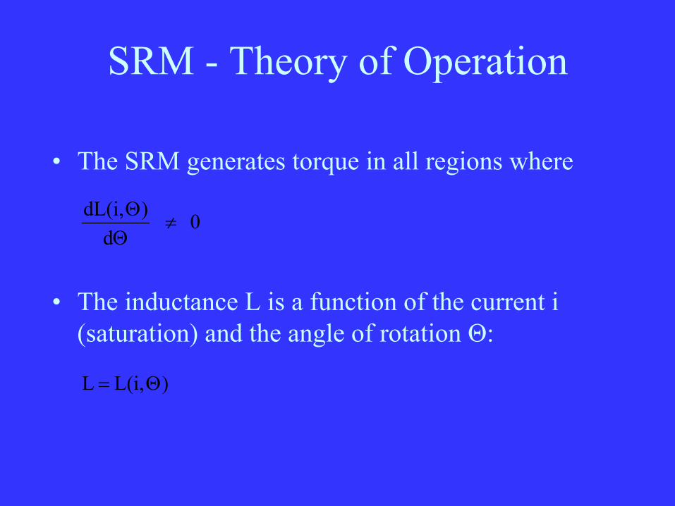
• The SRM generates torque in all regions where
0d
)dL(i,≠
ΘΘ
• The inductance L is a function of the current i (saturation) and the angle of rotation Θ:
)L(i, L Θ=
SRM - Theory of Operation
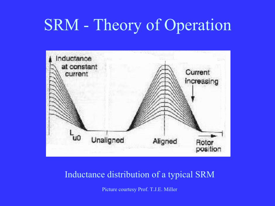
Inductance distribution of a typical SRMPicture courtesy Prof. T.J.E. Miller

SRM - Theory of Operation
Inductance and torque distribution of a typical SRM
SRM - Theory of Operation
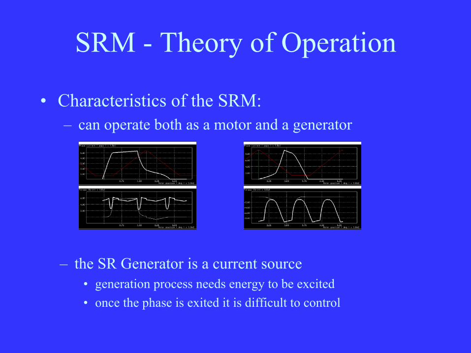
• Characteristics of the SRM:– can operate both as a motor and a generator
– the SR Generator is a current source• generation process needs energy to be excited• once the phase is exited it is difficult to control

Mathematical Analysis

SRM - Mathematical Analysis
• The mathematical analysis of the SR motor is challenging due to:
– non-linear airgap
– non-linear saturation
• Closed form models do exist for the SRM
– linear case: T = f(i2)

SRM - Mathematical Analysis
• Simulations are typically used to analyze the SRM:
– FEA (finite element analysis)
– PC-SRD (SRM Analysis software)
• Prof. Tim Miller, Glasgow, Speed Consortium
• Motorsoft Inc. is US distributor
– custom software

Definition of “Base Speed”

SRM - Definition of “Base Speed”
• The SRM allows the designer great flexibility when selecting a suitable motor winding
• To better compare machines we need to– define a specific operating point– define a specific winding

SRM - Definition of “Base Speed”
• When a single winding of the SRM is energized we can determine the winding current as:
( )ΘΦ
⋅+⋅Θ+⋅=dd
dtdi,iLiRV ω
where– V is the applied bus voltage
SRM - Definition of “Base Speed”
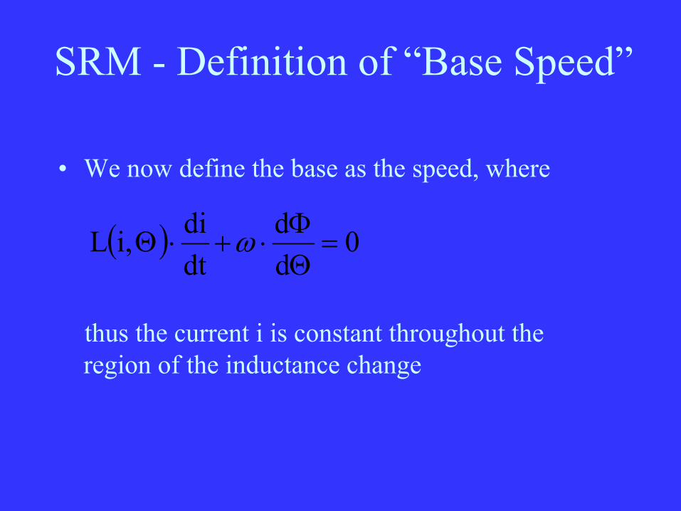
• We now define the base as the speed, where
( ) 0dd
dtdi,iL =
ΘΦ
⋅+⋅Θ ω
thus the current i is constant throughout the region of the inductance change
SRM - Definition of “Base Speed”
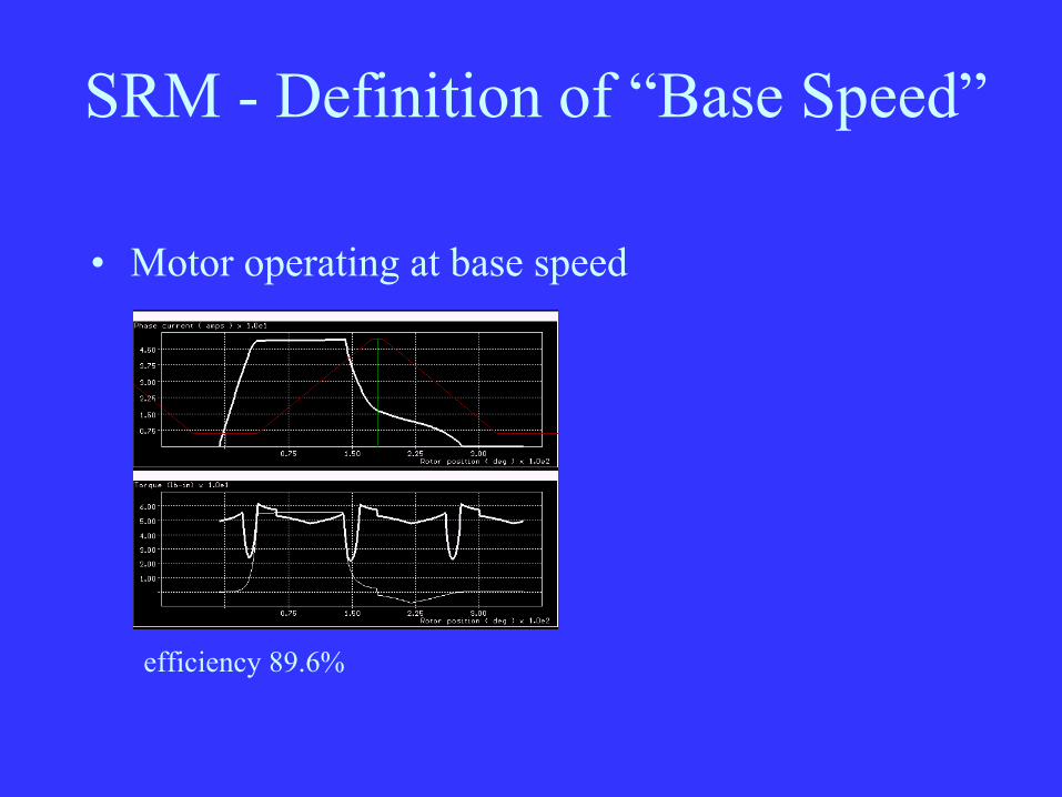
• Motor operating at base speed
efficiency 89.6%

SRM - Definition of “Base Speed”
• Motor operating above/below base speed
efficiency 90.4% (above) efficiency 87.6% (below)

SRM - Definition of “Base Speed”
• The “base speed” is a point of comparison
– it is a good point of reference
– it is an efficient operating point
– allows better comparisons between different motor designs
– simulations do show that the efficiency of the SRM drops a speeds greater than 2x”base speed”

Torque Ripple and Performance
SRM - Torque Ripple and Performance
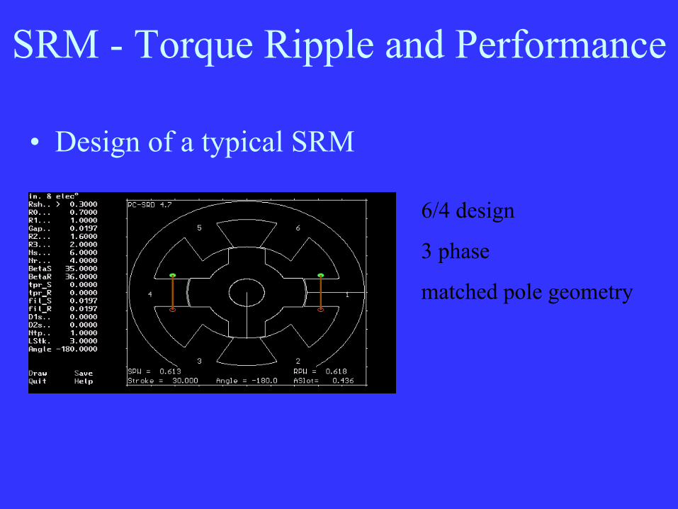
• Design of a typical SRM
6/4 design
3 phase
matched pole geometry

SRM - Torque Ripple and Performance
• Design of a typical SRM
shaft power: 1.0 kW
efficiency: 85.1 %
min/ave torque: 32%
SRM - Torque Ripple and Performance
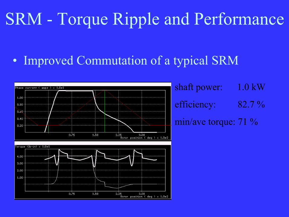
• Improved Commutation of a typical SRM
shaft power: 1.0 kW
efficiency: 82.7 %
min/ave torque: 71 %

SRM - Torque Ripple and Performance• Torque ripple appears to be reduced as the rotor tooth
is widened
Power: 3.1 kW 2.5 kW 1.8 kW 1.3 kWeff.: 89.6% 89.6% 90.2% 89.3%min/max 39% 48% 54% 67%
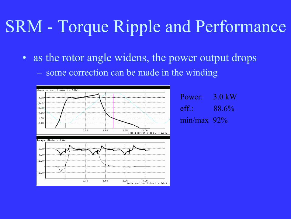
SRM - Torque Ripple and Performance• as the rotor angle widens, the power output drops
– some correction can be made in the winding
Power: 3.0 kWeff.: 88.6%min/max 92%

The n/n+2 SRM

The n/n+2 SRM
• Design of a 6/8 SRM
6/8 design
3 phase
mismatched pole geometry

The n/n+2 SRM
• Design of a 6/8 SRM
shaft power: 1.0 kW
efficiency: 86.7 %
min/ave torque: 88%
The n/n+2 SRM
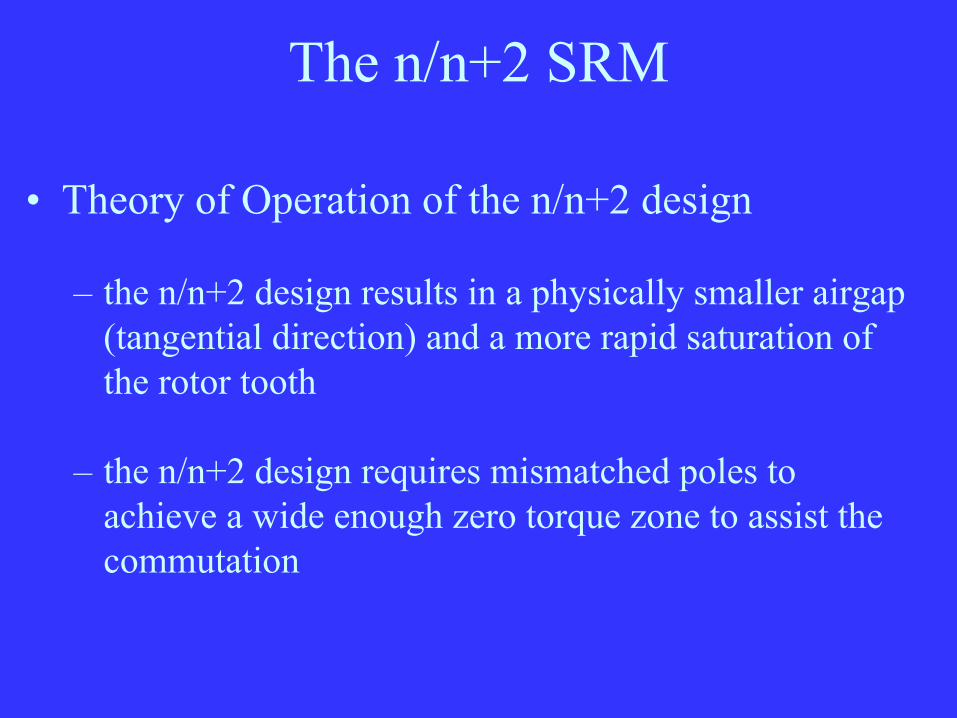
• Theory of Operation of the n/n+2 design
– the n/n+2 design results in a physically smaller airgap(tangential direction) and a more rapid saturation of the rotor tooth
– the n/n+2 design requires mismatched poles to achieve a wide enough zero torque zone to assist the commutation
The n/n+2 SRM
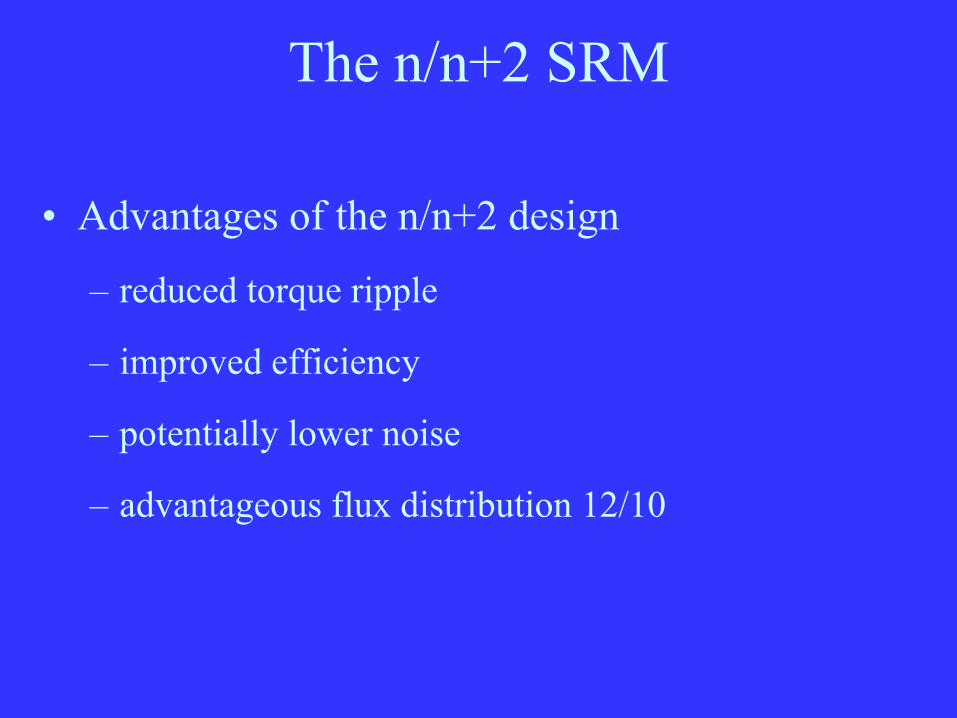
• Advantages of the n/n+2 design
– reduced torque ripple
– improved efficiency
– potentially lower noise
– advantageous flux distribution 12/10

The n/n+2 SRM
• advantageous flux distribution
The n/n+2 SRM
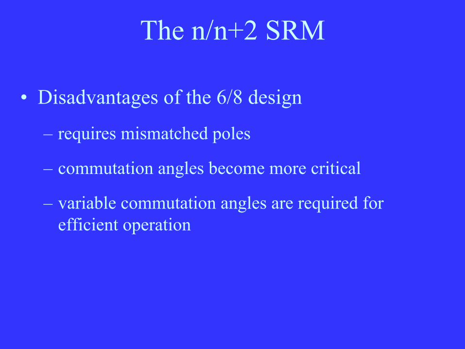
• Disadvantages of the 6/8 design
– requires mismatched poles
– commutation angles become more critical
– variable commutation angles are required for efficient operation

The n/n+2 SRM - Test Results

The n/n+2 SRM - Test Results
• The n/n+2 design offers advantages in some applications where low torque ripple is required
• The 4/6 motor is a 2 phase motor with improved starting torque
• We have built a 4/6 motor and its performance matches the simulations
• The motor has been tested up to 24 kRPM
The n/n+2 SRM - Test Results
• No comparative measurements of the acoustic noise between a 4/2 and a 4/6 motor have been performed to date
• Worldwide patent applications have been filed to protect the n/n+2 SRM geometry

The n/n+2 SRM - Future Work
The n/n+2 SRM - Future Work
• A more detailed analysis of the motor’s acoustic noise will be performed
• Several other n/n+2 motors are under construction to further validate the concept

The n/n+2 SRM - Future Work
• Potential Applications:
– Automotive fuel and water pumps (2 phase)
– Refrigeration compressors (2 phase)
– Small appliances (3 phase)