reduction of torque ripple in induction motor by arti cial
TRANSCRIPT

Turk J Elec Eng & Comp Sci
(2016) 24: 3492 – 3502
c⃝ TUBITAK
doi:10.3906/elk-1406-54
Turkish Journal of Electrical Engineering & Computer Sciences
http :// journa l s . tub i tak .gov . t r/e lektr ik/
Research Article
Reduction of torque ripple in induction motor by artificial neural multinetworks
Fatih KORKMAZ1,∗, Ismail TOPALOGLU1, Hayati MAMUR1, Murat ARI1, Ilhan TARIMER2
1Department of Electrical and Electronics Engineering, CankırıKaratekin University, Cankırı, Turkey2Department of Information Systems Engineering, Mugla SıtkıKocman University, Mugla, Turkey
Received: 10.06.2014 • Accepted/Published Online: 03.05.2015 • Final Version: 20.06.2016
Abstract:Direct torque control is used in the high performance control of induction motors. The most frequently faced
problem of it is high torque ripples. In this study, a new approach based on artificial neural multinetworks is presented
to overcome the problem. Two different artificial neural networks were suggested instead of vector selection and sector
determination processes in the conventional direct torque control method. The conventional and the proposed control
methods were evaluated on an induction motor through an experimental set. It was observed that the speed and torque
responses of the proposed method were better than those of the conventional method. The experimental results also
show that the proposed method would be a good alternative to the conventional method in induction motors.
Key words: Direct torque control, induction motor, neural networks
1. Introduction
Induction motors (IMs) have vital importance in industrial applications because of their well-known advantages.
In the past, IMs were generally used in constant speed applications, due to the fact that conventional speed
control methods were quite expensive or inefficient. Therefore, the use of DC motors was the only option for
variable speed industrial applications. However, today, the control methods of IMs have improved from simple
scalar control strategies to intelligent control algorithms, thanks to the advancement of digital signal processing,
power electronics, and microcontroller technologies [1].
Field-oriented control (FOC) opened a new era in the control of IMs for high performance industrial
applications. Since FOC decouples the stator currents to two independent components, as a result, an IM could
be controlled like DC motors. However, the success of FOC depends on many motor parameters. Therefore,
the performance of FOC is directly related to accurate parameter identification. Moreover, FOC has a complex
control structure on account of the necessity for coordinate transformation and the current regulators [2].
Takahashi [3] and Depenbrock [4] proposed two new control methods separately, which were called direct
torque control (DTC) and the direct self-control of IMs, in the 1980s. Unlike FOC, DTC has a simple control
structure. It does not require a complex coordinate transformation or any current regulators. The main idea
of DTC is to choose the best vector of the voltage, which causes the flux to rotate and to produce the desired
torque [5]. The core of conventional DTC (C-DTC) consists of a stator flux and a torque observer, a speed
controller, an optimum switching selector, a flux, and torque hysteresis controllers. The observer estimates
the actual stator flux and the torque by using the measured IM phase currents and voltages. The torque and
flux references are compared with the actual values. The hysteresis controllers then produce control signals
∗Correspondence: [email protected]
3492
KORKMAZ et al./Turk J Elec Eng & Comp Sci
[6]. Therefore, the flux and the torque can be directly controlled with the flux and the torque errors by the
hysteresis controllers.
Therefore, when compared with FOC, it should be noted that DTC has not only a simple control structure,
but also robustness to the parameter variations of the IM. The calculation of the stator voltage vector requires
only a stator resistance from the IM parameters. Any possible variation due to the rising IM temperature
in stator resistance would have a direct impact on the DTC performance. Therefore, this issue should be
considered for systems operating for a long period of time. However, like every control structure, DTC has also
some disadvantages such as high currents and torque ripples, difficulty to control torque and flux at very low
speeds, and variable switching frequency behavior [7].
Over the last decades, DTC has become most popular due to its advantages mentioned above. Further-
more, a large number of studies to date are summarized as below:
• The investigation of different switching methods and inverter topologies [8,9]
• The implementation of artificial intelligence methods on different sections of the system [10,11]
• The investigation of different observer models [12,13].
In this paper, a new artificial neural network (ANN) approach in DTC (ANN-DTC) is presented, and two
different ANN models were designed to determine the stator flux vector and optimum switching states of the
inverter. Detailed information about the recommended approach is given in Section 2. The experimental studies
are explained and the results of the experiments realized through torque and speed curves of an IM are given
in Section 3. The experimental results, discussions, and comparisons are given in the last section.
2. Materials and methods
Over the last few decades, ANNs have gained remarkable significance because of their ability to learn, like the
human brain. The potential learning abilities of ANNs extend beyond the high computation rates with the
parallelism of the networks [14].
ANNs are known as computational models that are inspired by biological nervous systems. In these
models, a large number of interconnected processing points (neurons) are created to work together to solve
specific problems. ANNs are typically classified into three types of parameters: interconnection structure of
different neuron layers, the training algorithm that is used in the training process, and activation functions
that convert input data into the output of neurons. The most popular ANN employed by researchers is the
multilayer feed forward ANN trained by the back propagation algorithm [15]. A recently published study has
examined utilities of ANN in terms of prediction and comparison [16].
The ANN method provides computational modeling of complex and nonlinear mathematical structures. It
also provides robust systems to store the data on the entire network and working ability with missing parameters
in some situations. However, DTC seems simple when compared with other control methods like FOC. The
DTC method also has a complex mathematical process of modeling of look-up tables, to select switching states,
and to determine the stator flux section.
In this study, two different feed forward ANNs were designed to select switching states and determine the
stator flux sector. Determining of the number of neurons normally requires several stages of iteration because
there is no unique way to determine the optimum number of neurons. An error of estimation would be high if
3493
KORKMAZ et al./Turk J Elec Eng & Comp Sci
the number of neurons is low. Conversely, the network would tend to memorize rather than learn [17]. In order
to determine the optimum ANN structure, some off-line training results are effective in both of them.
The first model of the ANN was created to determine the flux sector. The alpha and beta components
of the stator currents were operated as inputs of the flux sector determining ANN (ANNλsector) as shown in
Figure 1.
Figure 1. Presentation of stator flux sector on the ANNλsector structure.
In Figure 1, iα , iβ , and λsector are stator currents components and flux sector data, respectively.
The ANNλsector was created in three layers and it has two neurons in the input layer, six neurons in
the hidden layer, and one neuron in the output layer. The hidden layer neurons have a hyperbolic tangent
sigmoid transfer function (tansig) and the output layer neuron has a linear transfer function (purelin). The
input data patterns were normalized to per unit values in the input layer and they were converted to actual
values (denormalization) in the output layer. The ANNλsector was trained off-line with the gradient descent
(Levenberg–Marquardt) algorithm. The input and output data vectors were obtained by storage as a vector
of the C-DTC stator flux sector determining block inputs and outputs. Fifty thousand data bits were used
throughout the training process (35,000 data bits for training, 7500 data bits for validation, and 7500 data bits
for testing). The offline training was executed for approximately 20 min with an AMD Phenom II X4 3.1 GHz
processor and the best validation performance was obtained (mean squared error: 0.061978) at epoch 757 as
shown in Figure 2.
The second model of the ANN was created to determine the switching states. As given in Figure 3, the
torque–flux hysteresis comparator outputs and the sector of the flux were employed as inputs of the switching
states selector ANN (ANNsw).
In Figure 3, Thys , λhys , and λsector are the torque and the flux hysteresis outputs, and the flux sector
data, respectively. The MATLAB/Simulink structure of the ANNsw is shown in Figure 4.
The ANNsw was created in three layers and it has three neurons in the input layer, six neurons in the
hidden layer, and one neuron in the output layer. The hidden layer neurons have a hyperbolic tangent sigmoid
transfer function (tansig). The output layer neuron also has a linear transfer function (purelin). The ANNsw
was also trained off-line with the gradient descent (Levenberg–Marquardt) algorithm. The input and output
data vectors were obtained by storage as a vector of the C-DTC switching state generating block inputs and
outputs. Twenty-five thousand data bits were used throughout the training (15,000 data bits for training, 5000
data bits for validation, and 5000 data bits for testing). The offline training was carried out for approximately
15 min by an AMD Phenom II X4 3.1 GHz processor and the best validation performance was achieved (mean
squared error: 0.076176) at epoch 543 as shown in Figure 5.
3494

KORKMAZ et al./Turk J Elec Eng & Comp Sci
Figure 2. Training performance of the ANNλsector .
Figure 3. Presentation of switching states on the ANNsw structure.
Figure 4. The ANN structure on MATLAB/Simulink.
The schematic diagram of the experimental setup is given in Figure 6. It consists of a host computer
with dSPACE 1103 DSP (digital signal processor), a measurement unit, an inverter, and a motor-load group.
3495

KORKMAZ et al./Turk J Elec Eng & Comp Sci
Figure 5. Training performance of the ANNsw .
Figure 6. Schematic diagram of the experimental setup.
In the flux and torque observer model, the stator flux vector was calculated using the following equations:
λα =
∫(Vα −Rsiα) dt (1)
λβ =
∫(Vβ −Rsiβ) dt (2)
λ =√λ2α + λ2
β , (3)
where λα−λβ , iα−iβ , and Vα−Vβ indicate the stator flux, the measured stator current and voltage components,
respectively; α and β indicate components; and Rsdepicts the stator resistance.
3496

KORKMAZ et al./Turk J Elec Eng & Comp Sci
The electromagnetic torque of an IM is estimated using the following equation:
Te =3
2p(λαiβ − λβiα), (4)
where p is the number of pole pairs [18].
3. Results and discussion
The dSPACE board can be integrated on MATLAB/Simulink, as one of the well-known engineering software
packages. The Control Desk software is another useful feature of dSPACE that allows a graphic user interface.
The user can observe the real-time responses of a control system and the parameters of the control system can
also be controlled in real time.
MATLAB/Simulink Real-Time Interface (RTI) block that automatically embeds the Real-time Workshop
(generated C codes) for the implementation of designed MATLAB/Simulink models on the dSPACE board
provides a connection between the controller board and MATLAB/Simulink. This capability of dSPACE’s
allows a system designer to fully focus on the actual design process and fast determination and analysis of
possible errors [19].
To perform the experimental studies, Fuji IGBT dual modules based on a voltage source inverter with
gate driver circuits and an opto-isolation board were designed. A single-phase diode rectifier module with
capacitive filters was used to obtain the DC voltage for the inverter. All phase voltages and currents were
measured with LEM sensors (LV-25p, LA-25np). An overview of the experimental setup is given in Figure 7.
Figure 7. Overview of the test desk.
The parameters of the three-phase IM used in experimental studies are given as follows in SI units: P =
1.1 kW, U = 220/380 V, I = 4.5/2.6 A, cosφ = 0.85, 2820 rpm, f = 50 Hz, Rs = 7.13 Ω, and sampling time
= 50 mu s.
Experimental studies were carried out in order to show the performance and feasibility of the proposed
DTC method. The dSPACE board was programmed in the MATLAB/Simulink Real-Time-Workshop environ-
ment as shown in Figure 8.
In the C-DTC, two hysteresis controllers and stator flux section data are input parameters of a look-up
table, which generates the switching states.
3497

KORKMAZ et al./Turk J Elec Eng & Comp Sci
Figure 8. MATLAB/Simulink block diagram of the proposed ANN-based method.
Therefore, each of these three parameters individually affects system performance. It means that a small
change in one of these parameters directly varies the output data of the switching states without considering the
other two parameters. In the proposed ANN based system, the switching states and the stator flux angle were
calculated by the ANNs. Thus, separately working behaviors of the parameters were eliminated. The outputs
for the calculation processes were determined by an assessment of all input parameters. In other words, the
input parameters of the blocks were combined with the ANN structure to determine changes in the required
output values.
Figure 9. C-DTC controlled speed response under con-
stant speed-variable load condition.
Figure 10. ANN-DTC controlled speed response under
constant speed-variable load condition.
In order to evaluate a fair comparison of performances with the C-DTC and the proposed ANN-DTC,
different ranges of speed and load values were applied to the IM. In the first part of the experimental tests, the
IM was operated at a constant speed of 2800 rpm variable load conditions. In the tests, the IM was started at
no load condition and switched to a full-load of 3 Nm at the third second and then switched to half-load of 1.5Nm at the sixth second. The experimental results of the first part of the tests are given in Figures 9–12.
3498
KORKMAZ et al./Turk J Elec Eng & Comp Sci
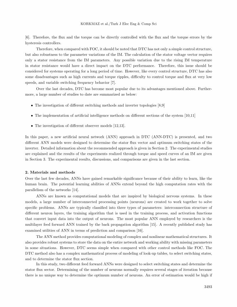
Figure 11. C-DTC controlled torque response under con-
stant speed-variable load condition.
Figure 12. ANN-DTC controlled torque response under
constant speed-variable load condition.
Under constant speed-variable load working conditions, Figures 9 and 10 show the responses of speed
for the C-DTC and the ANN-DTC, respectively. It can be seen that similar transient responses were obtained
in the IM. When the steady-state performances were compared, the same robustness was achieved against the
variation of load in both of the methods.
The torque responses of the C-DTC and the ANN-DTC are given in Figures 11 and 12, respectively. By
the ANN-DTC, the ripple in the torque was reduced under different load conditions.
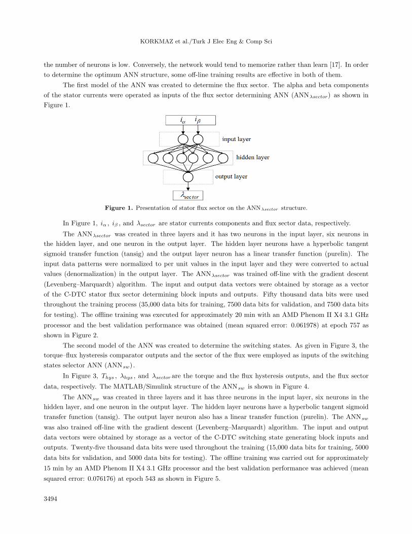
In the second part of the tests, the IM was tested at a constant torque of 3 Nm variable speed conditions.
In the tests, the IM was started at a low speed of 280 rpm, switched then to a speed of 2800 rpm at the third
second, and then to the half-rate speed of 1400 Nm at the sixth second. The experimental results of the second
part of the tests are given in Figures 13–16.
Figure 13. C-DTC controlled speed response under con-
stant load-variable speed condition.
Figure 14. ANN-DTC controlled speed response under
constant load-variable speed condition.
3499

KORKMAZ et al./Turk J Elec Eng & Comp Sci
Figure 15. C-DTC controlled torque response under con-
stant load-variable speed condition.
Figure 16. ANN-DTC controlled torque response under
constant load-variable speed condition.
Figures 13 and 14 indicate the responses of speed for the C-DTC and the ANN-DTC in constant load-
variable speed conditions, respectively. It can be inferred that both methods still have nearly the same transient
responses and steady-state performances.
Figures 15 and 16 present the torque responses of the C-DTC and the ANN-DTC. Again, it should
be pointed out that the ripple in torque with the ANN-DTC is less than that with the C-DTC at all speed
conditions.
In order to further compare, the RMS values of torque ripples were calculated under variable load and
speed conditions. In this calculation, torque values were analyzed by dividing them into two separate parts: a
positive torque ripple (PTR) and a negative torque ripple (NTR). The values that are greater than the reference
value were labeled as PTR and the values less than the reference value were labeled as NTR. The bandwidthof torque ripple (BTR) was calculated as given in the following equation:
BTRrms = PTRrms −NTRrms (5)
The BTR results are given in the Table. The BTR values proved that torque ripples of the IM were reduced
by a rate of approximately 60%.
Table. The RMS values of bandwidth torque ripples.
IM load (Nm) 0 1.5 3
BTRrms 280 rpm
C-DTC 1.18 0.58 0.52ANN-DTC 0.48 0.25 0.23Reduction rate (%) 59.32 56.89 55.76
BTRrms 2800 rpm
C-DTC 1.08 0.54 0.48ANN-DTC 0.42 0.22 0.20Reduction rate (%) 61.1 59.25 58.33
During the implementation of the experimental system, different sampling times were applied to the
controller. The controller board has a 1 GHz processor speed. While the C-DTC model was built in 35 mu s
sampling time, the ANN-DTC model had an overloading error in this sample time. After several different time
attempts, both models were built in 50 mu s sampling time. As a result of the attempts, the ANN-DTC method
3500

KORKMAZ et al./Turk J Elec Eng & Comp Sci
required approximately 30% more computation time compared to the C-DTC. Hence, in order to implement
the ANN-DTC method, designers would need to operate more powerful and quicker microcontrollers.
The experimental studies stated that the ANN-DTC method can be considered a good alternative to
overcome the high torque ripples in the C-DTC method.
4. Conclusions
In this paper, ANN-based flux sector determination and a switching voltage vector selection method were
proposed for DTC of IMs. The proposed method performance was compared with the C-DTC method under
different speed and load conditions. The performance was also tested by experimental studies. Even though
the ANN-DTC method ensured almost the same dynamic responses in a transient state, the torque ripples
were remarkably reduced in the steady state. In addition, the complex mathematical structure of the C-DTC
was simplified through the learning abilities of the ANNs. By the proposed method, not only did the high
torque ripples remarkably decrease, but also its fast dynamic response was stabilized. Of course, the ANN
structures need to have powerful and high speed microcontrollers for implementation. This situation seemed to
be a drawback of the ANN systems used. The experimental results show that the proposed ANN-based DTC
method can become a good alternative for DTC-controlled IMs, and it is also expected to be applicable to other
motor types such as permanent magnet synchronous motors and brushless DC motors.
References
[1] Bleizgys V, Baskys A, Lipinskis T. Induction motor voltage amplitude control technique based on the motor
efficiency observation. Elektron Elektrotech 2011; 3: 89-92.
[2] Lin G, Xu Z. Direct torque control of induction motor using neural network. In: Information Science and Engineering
(ICISE); 26–28 December 2009; pp. 4827-4830.
[3] Takahashi I, Noguchi T. A new quick-response and high efficiency control strategy of an induction motor. IEEE T
Ind Appl 1986; 5: 820-827.
[4] Depenbrock M. Direct self control of inverter-fed induction machines. IEEE T Power Electr 1988; 4: 420-429.
[5] Vas P. Sensorless Vector and Direct Torque Control. New York, NY, USA: Oxford University Press, 1998.
[6] Okumus HI, Aktas M. Adaptive hysteresis band control for constant switching frequency in DTC induction machine
drives. Turk J Electr Eng & Comp Sci 2010; 18: 59-69.
[7] Zang C, Cao X. Direct torque control based on space vector modulation with adaptive neural integrator for stator
flux estimation in induction motors. In: Fifth International Conference on Natural Computation (ICNC 2009);
14–16 August 2009; Tianjian, China. pp. 355-359.
[8] Casadei D, Serra G, Tani A. The use of matrix converters in direct torque control of induction machines. IEEE T
Ind Electron 2001; 48: 1057-1064.
[9] Casadei D, Serra G, Tani A. Implementation of a direct torque control algorithm for induction motors based on
discrete space vector modulation. IEEE T Power Electr 2000; 15: 769-777.
[10] Benaicha S, Zidani F, Said RN, Said MSN. Direct torque with fuzzy logic torque ripple reduction based stator flux
vector control. In: International Conference on Computer and Electrical Engineering (ICCEE ’09); 28–30 December
2009; Dubai, UAE. pp. 128-133.
[11] Sadati N, Kaboli S, Adeli H, Hajipour E, Ferdowsi M. Online optimal neuro-fuzzy flux controller for DTC based
induction motor drives. In: Applied Power Electronics Conference and Exposition; 15–19 February 2009; Twenty-
Fourth Annual IEEE. pp. 210-215.
3501

KORKMAZ et al./Turk J Elec Eng & Comp Sci
[12] Tan Z, Li Y, Zeng Y. A three-level speed sensorless DTC drive of induction motor based on a full-order flux observer.
In: International Conference on Power Systems Technology: 13–17 October 2002; Kunming, China: pp. 1054-1058.
[13] Ya G, Weiguo L. A new method research of fuzzy DTC based on full-order state observer for stator flux linkage.
In: IEEE 2011 International Conference on Computer Science and Automation Engineering (CSAE); 10–12 June
2011. pp. 104-108.
[14] Aktas M, Okumus HI. Stator resistance estimation using ANN in DTC IM drives. Turk J Electr Eng & Comp Sci
2010; 18: 197-210.
[15] Kumar R, Gupta RA, Bhangale SV, Gothwal H. Artificial neural network based direct torque control of induction
motor drives. International Conference on Information and Communication Technology in Electrical Sciences
(ICTES 2007); 20–22 December 2007; IET–UK. pp. 361-367.
[16] Balli S, Tarımer I. An application of artificial neural networks for prediction and comparison with statistical
methods. Elektron Elektrotech 2013; 2: 101-105.
[17] Neema DD, Patel RN, Thoke AS. Rotor flux and torque estimator for vector controlled induction drive using ANN.
International Joint Conference on Neural Networks (IJCNN 2009); 14–19 June 2009; Atlanta,Georgia, USA. pp.
2215-2220.
[18] Korkmaz F, Cakır MF, Topaloglu I, Gurbuz R. Artificial neural network based DTC driver for PMSM. International
Journal of Instrumentation and Control Systems 2013; 3: 1-7.
[19] Abbou A, Nasser T, Mahmoudi H, Akherraz M, Essadki A. Induction motor controls and implementation using
DSPACE. WSEAS Transactions on Systems and Control 2012; 1: 26-35.
3502