sqxf shell & yoke assembly procedure j.c. perez nicolas bourcey, paolo ferracin, javier parrilla...
TRANSCRIPT


SQXF Shell & Yoke Assembly Procedure
J.C. Perez
Nicolas Bourcey, Paolo Ferracin, Javier Parrilla Leal, Mariusz Juchno

Shells ready to be assembled
July 2014J.C. Perez 3
4 feet assembly base
The shells are instrumented with the strain gauges before starting the assembly sequence

Lower shell positioning
July 2014J.C. Perez 4
Longitudinal positioningsupport for the shell
Longitudinal positioning support for a ¼ yoke
The base plate will be levelled and bolted to the floor
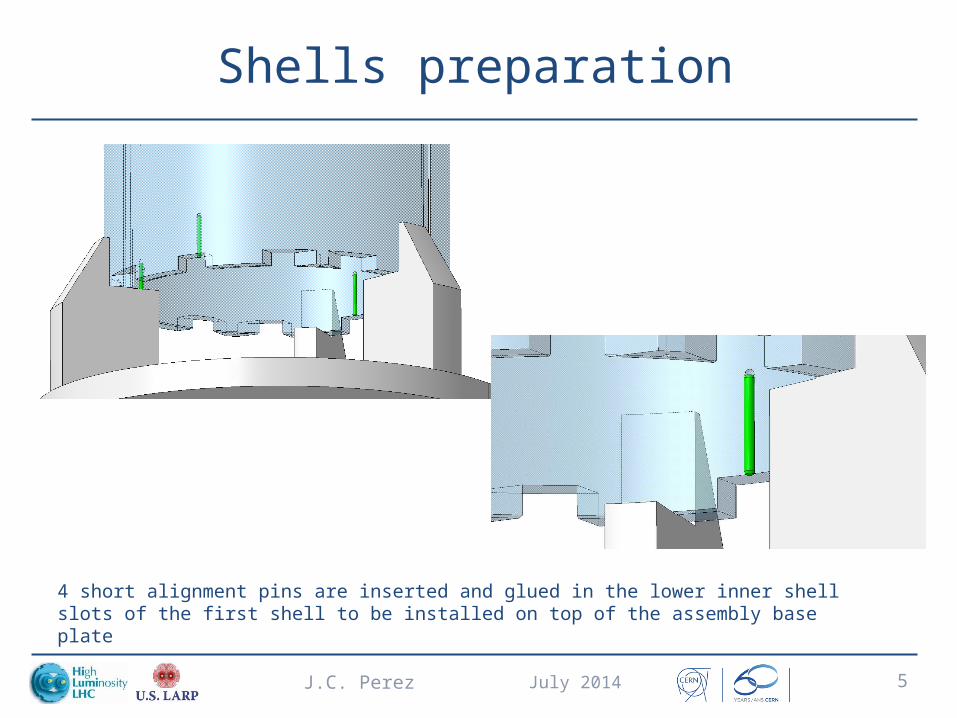
Shells preparation
July 2014J.C. Perez 5
4 short alignment pins are inserted and glued in the lower inner shell slots of the first shell to be installed on top of the assembly base plate

Shell lifting
July 2014J.C. Perez 6
The shells are manipulated using a 4 sling lifting tool and adjustable bolted lifting eyes.

Mounting lower shell
July 2014J.C. Perez 7
The lower shell is positioned on top of the assembly base plate

Longitudinal offset yoke/shell
July 2014J.C. Perez 8
1 mm gap for offset between ¼ yoke and shell
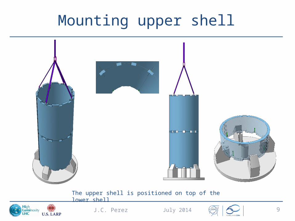
Mounting upper shell
July 2014J.C. Perez 9
The upper shell is positioned on top of the lower shell
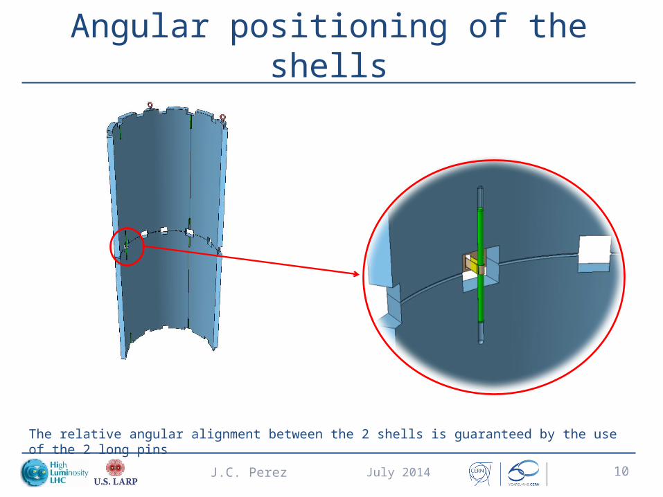
Angular positioning of the shells
July 2014J.C. Perez 10
The relative angular alignment between the 2 shells is guaranteed by the use of the 2 long pins

Mounting angular positioning pins
July 2014J.C. Perez 11
The 2 long pins are inserted in the correspondent grooves and kept in position by using a dedicated holding tool

Securing shells assembly
July 2014J.C. Perez 12
4 aluminum profiles mounted around the shells and clamped with adjustable straps, prevent the upper shell to fall

¼ yoke rotation
July 2014J.C. Perez 13
The ¼ yokes are equipped with a dedicated lifting tool and installed on a pivoting table. The yokes will be inserted on the shells in vertical position

First ¼ yoke insertion (1/2)
July 2014J.C. Perez 14

First ¼ yoke insertion (2/2)
July 2014J.C. Perez 15
The angular alignment of the first ¼ yoke is defined by 1 long middle pin and 2 small pins located at the shell extremities

Joke clamping
July 2014J.C. Perez 16
Dedicated clamping tools will be used to radially clamp the ¼ yoke in the shells
Upper radial clamp
Lower radial clamp

Removing central pin holding tool
July 2014J.C. Perez 17
The holding tooling of the middle pin is removed before clamping the yoke at its final radial position (required gap between yoke and shell to allow pin removal ± 0.3 mm)
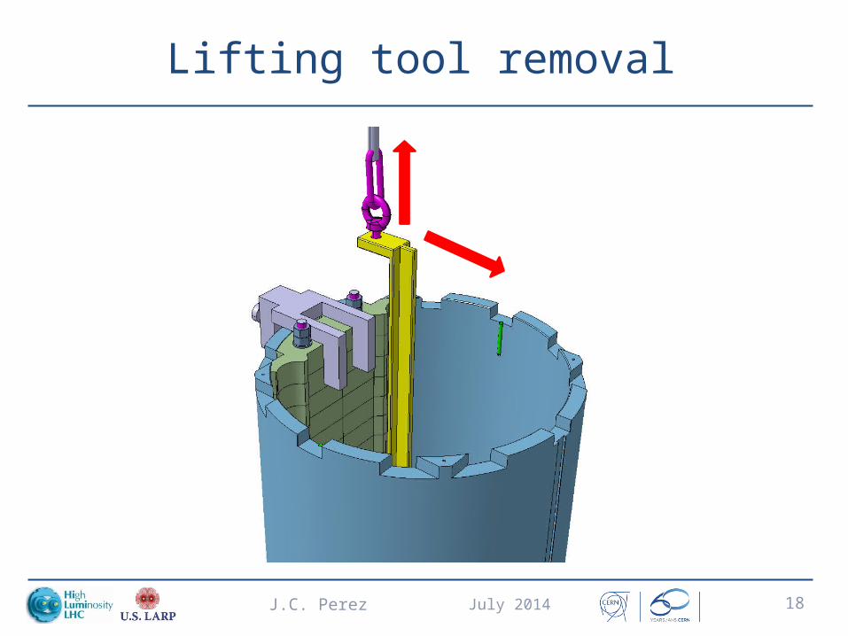
Lifting tool removal
July 2014J.C. Perez 18

July 2014J.C. Perez 19
Second ¼ yoke insertion
The second ¼ yoke is inserted and clamped like the first one

3rd ¼ yoke insertion(1/4)
July 2014J.C. Perez 20
Using the same assembly procedure, the 3rd yoke will interfere with the yokes already installed.

3rd ¼ yoke insertion(2/4)
July 2014J.C. Perez 21

3rd ¼ yoke insertion(3/4)
July 2014J.C. Perez 22
The Yoke lifting tool is equipped with 2 guiding wheels forcing the yoke against the plastic spacers
2 longitudinal plastic spacers will be used to guarantee a constant gap between yoke and shell preventing interference with the already inserted yokes

3rd ¼ yoke insertion(4/4)
July 2014J.C. Perez 23
The yoke is temporally clamped and the 4 (40mm) short alignment pins are inserted
on the grooves before removing the plastic spacers
The yoke is clamped onto its final position and the lifting tool is removed
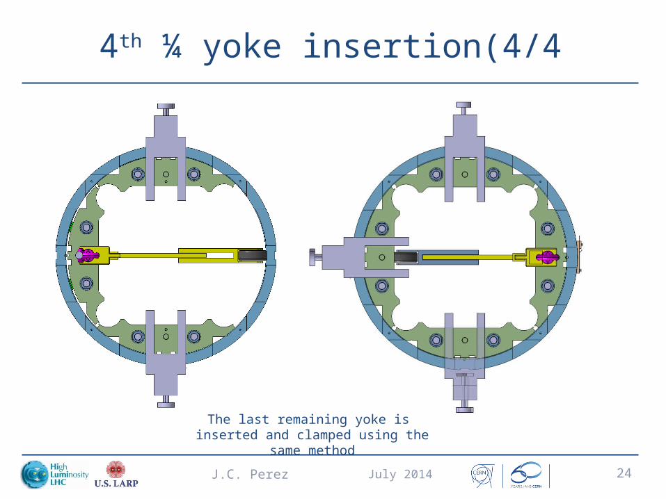
4th ¼ yoke insertion(4/4
July 2014J.C. Perez 24
The last remaining yoke is inserted and clamped using the same method
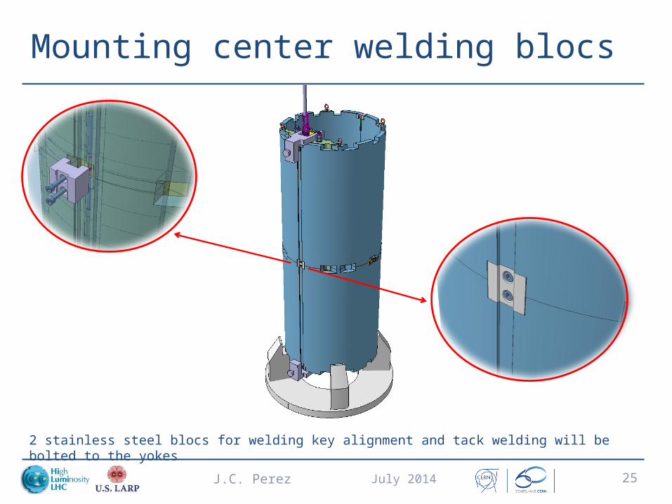
Mounting center welding blocs
July 2014J.C. Perez 25
2 stainless steel blocs for welding key alignment and tack welding will be bolted to the yokes

Bladders support structure for shell loading
July 2014J.C. Perez 26

Yoke pre-loading
July 2014J.C. Perez 27
A cross-shape support will be inserted in the structure to support the bladders for shell pre-loading operation

Bladders insertion
July 2014J.C. Perez 28
4 bladders of 1549 * 57 mm will be used for pre-loading operation

Yoke keys insertion
July 2014J.C. Perez 29

Pre-loading tool removal
July 2014J.C. Perez 30

Yoke loading sequence
July 2014J.C. Perez 31

Lifting Yoke and Shell
July 2014J.C. Perez 32
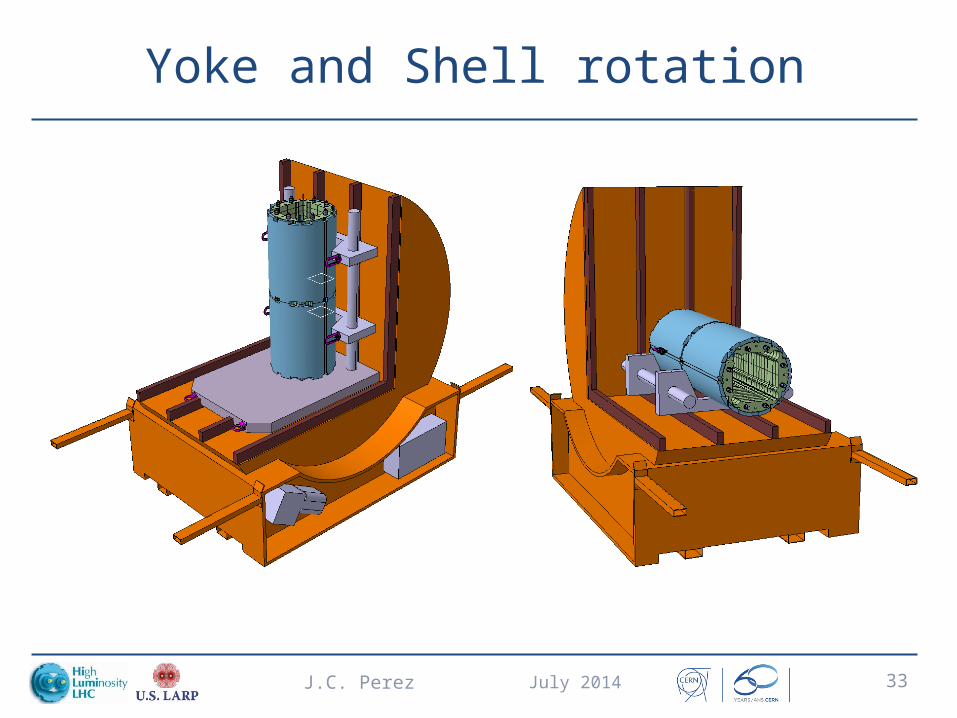
Yoke and Shell rotation
July 2014J.C. Perez 33

And now real pieces !!!
July 2014J.C. Perez 34

And now real pieces !!!
July 2014J.C. Perez 35
