spreadmaster - c-daxau.c-dax.co.nz/files/resources/manuals/2400-7000-10 spreadmaster g… · 4...
TRANSCRIPT

OWNER’S MANUAL
FOR THE
SPREADMASTER g e n e r a t i o n 2
MOUNTED SPREADER
C-Dax Ltd
PO Box 1010, 145 Harts Road
Tiritea, Palmerston North
Ph:06 354 6060
Fax:06 355 3199
E-Mail: [email protected]
www.c-dax.co.nz

- 2 -
SAFETY PRECAUTIONS
SPREADMASTER
AN IMPORTANT MESSAGE FOR OWNERS & OPERATORS OF
C-Dax ATTACHMENTS/ACCESSORIES
Be warned of the dangers of loading your ATV or other vehicle in excess of its carrying capacity.
It is important to understand that any loads or attachments whether fastened to or placed on a
vehicle or ATV will alter the stability or handling characteristics of that vehicle or ATV.
Spray tanks or other equipment must be filled only to a level where the gross weight is within the
load limit of the ATV or other vehicle.
Safety is a primary concern in the design, manufacture, sale, and use of spray tanks and other
equipment. As manufacturers of spray tanks and other equipment we want to confirm to you, our
customers, our concern for safety. We take this opportunity to remind you about the simple, basic
and common sense rules of safety when using spray tanks and other equipment. Failure to follow
these rules can result in severe injury or death to operators and bystanders.
It is essential that everyone involved in the assembly, operation, transport, maintenance and
storage of this equipment be aware, concerned, prudent and properly trained in safety.
This also applies to equipment that is loaned or rented to someone who has not read the owner’s
manual and is not familiar with the operation of application equipment.
• NEVER EXCEED THE LOAD LIMIT CAPACITY OF THE ATV OR OTHER VEHICLE.
• ALL ATV AND TRAILED EQUIPMENT TYRES SHOULD BE INFLATED TO
MANUFACTURERS RECOMMENDED OPERATING PRESSURES.
• PLEASE NOTE THAT FILLING THE SPRAY TANK OR OTHER EQUIPMENT COMPLETELY
AND OR THE ATTACHMENT OF ADDITIONAL EQUIPMENT TO THE ATV MAY EXCEED THE
ATV’S MAXIMUM LOAD CAPACITY, AND ADVERSELY AFFECT THE STABILITY OF THE
ATV OR OTHER VEHICLE.
• CARGO SHOULD BE PROPERLY DISTRIBUTED AND SECURELY ATTACHED.
• REDUCE SPEED WHEN CARRYING CARGO OR PULLING A TRAILER OR TRAILED
APPLICATION EQUIPMENT AND ALLOW GREATER DISTANCE FOR BRAKING.
• NEVER ALLOW ANYONE TO RIDE ON YOUR SPRAYER OR OTHER EQUIPMENT.
• ALWAYS FOLLOW THE INSTRUCTIONS IN THE OWNER’S VEHICLE MANUAL FOR
CARRYING CARGO OR PULLING A TRAILER.
• PROPER MAINTENANCE IN LINE WITH MANUFACTURER’S RECOMMENDED
MAINTENANCE PROCEDURES IS ESSENTIAL.
• BEFORE APPLYING CHEMICALS, READ THE LABEL OF THE CHEMICAL
MANUFACTURER OR SUPPLIER FOR PERSONAL PROTECTIVE EQUIPMENT AND
OPERATE AS RECOMMENDED.
• THE SAFETY OF ALL CHEMICALS USED IN AGRICULTURE IS UNDER THE JURISDICTION
OF A GOVERNMENT AGENCY, IE N.Z. MINISTRY FOR THE ENVIRONMENT; USA
ENVIRONMENTAL PROTECTION AGENCY. FURTHER LOCAL GOVERNMENT OR STATE
LAWS MAY APPLY.
Throughout this manual there are highlighted text boxes containing warnings, cautions and notes.
Warnings are mandatory instructions to prevent serious injury or permanent damage.
Cautions are advisory instructions to ensure reliable operation of the equipment.
Notes are for convenient operation
WARNING

3
For safe operation ensure that your vehicle is adequate for the task. The maximum tare weight is
60 Kg or as recommended by the vehicle manufacturer.
SAFTEY PRECAUTIONS CONT…
� Read the instruction book thoroughly before attempting to install or operate the spreader.
Failure to read the manual constitutes misuse of the equipment and will invalidate the
warranty.
� The maximum loaded weight of the spreader should not exceed the manufacturer’s specific
carrier weight limit.
� Never turn the spreader on if there is someone standing near the spinner.
� Make sure the spinner is turned off and the shutter is closed before loading the hopper.
� Never use dirty product or product with stones or lumps.
� Never replace the fuse with one larger than the maximum recommended rating of 20 Amps.
� If using the spreader on hilly terrain, the payload should be reduced to ensure that the
spreader and vehicle stability are not compromised.
� Never allow anyone to ride on the spreader.
� Keep the spreader in good condition. Cleanliness and maintenance are essential for safe and
trouble free operation. Never leave product in the hopper or store the spreader without
cleaning it.

4
C-Dax SPREADMASTER G2
OWNER’S MANUAL
(Pt.No.2400-7000 Issue 10, Dated Dec 2010)
TABLE OF CONTENTS
2 Safety Precautions
3 Safety Precautions Cont.
4 Table of Contents
5 Introduction
Description
6 Specifications
Order Information
Optional Equipment
7 Warranty
Liability
8 Installation
Flatdeck
9 Quick Smart spreader attachment
Quick Smart attachment system
Wiring
Operation
10 System Interconnections
Calibration
11 Calibration Guide
12 Operating the Spreader
Adjusting the Spread Pattern
Maintenance
Before Use
13 After Each Use or Daily When in Use
Repairs
Removal of the Motor
Removal of the Spinner
Removal of the Agitator Shaft
Removal of the Delivery chute
Removal of the Hopper
Removal of the Shutter
Reassembly
14 Installing a New Agitator Flail
Trouble Shooting
15 Exploded Parts Diagram
16 Parts List

5
INTRODUCTION
Congratulations on the purchase of your new SpreadMaster spreading unit. You join the many
farmer’s world-wide who have recognised the remarkable usefulness of this unique piece of
equipment.
DESCRIPTION
The C-Dax SpreadMaster is designed for accurate application of seeds, fertilisers, and powdered
products.
The uniquely designed 70 Litre translucent non-corrosive polyethylene hopper is specially profiled
for good product flow and ease of filling. The convenient hinged polyethylene snap shut lid ensures
secure product storage. A two-stage agitator and stainless steel shutter and choke assembly
ensures even and controlled flow of product to the spinner. A sturdy convenient shutter handle
ensures positive open and closed action of the shutter. A unique six-vane stainless steel spinner
driven by a 12 VDC motor provides 180 degrees spread of product.
The SpreadMaster can be ordered in three configurations:
� The SpreadMaster can be bolted to a flat vertical surface such as the tailboard of a trailer.
Part number 3000
� The SpreadMaster can be ordered with a Quick Smart system. Complete with the
convenient Quick Smart™ attachment system for the rear carrier of ATVs and a Quick
smart spreader bracket. Part numbers 3000, 1073 and 3008
� The SpreadMaster can be ordered with a Quick Smart spreader bracket. Part numbers
3000 and 3008
6
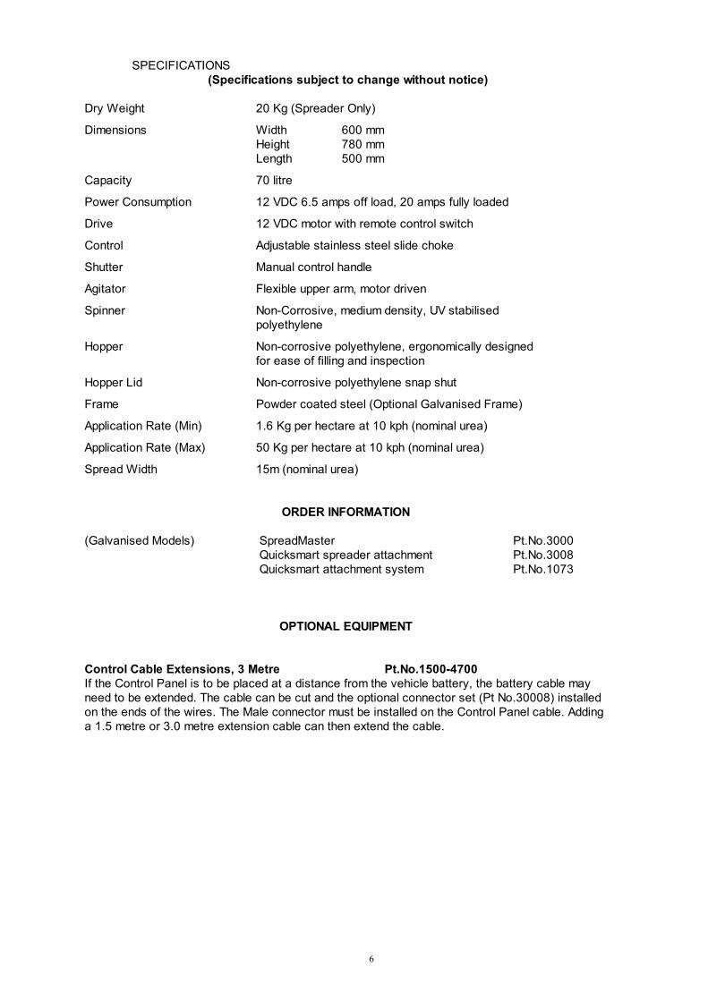
SPECIFICATIONS
(Specifications subject to change without notice)
Dry Weight 20 Kg (Spreader Only)
Dimensions Width 600 mm
Height 780 mm
Length 500 mm
Capacity 70 litre
Power Consumption 12 VDC 6.5 amps off load, 20 amps fully loaded
Drive 12 VDC motor with remote control switch
Control Adjustable stainless steel slide choke
Shutter Manual control handle
Agitator Flexible upper arm, motor driven
Spinner Non-Corrosive, medium density, UV stabilised
polyethylene
Hopper Non-corrosive polyethylene, ergonomically designed
for ease of filling and inspection
Hopper Lid Non-corrosive polyethylene snap shut
Frame Powder coated steel (Optional Galvanised Frame)
Application Rate (Min) 1.6 Kg per hectare at 10 kph (nominal urea)
Application Rate (Max) 50 Kg per hectare at 10 kph (nominal urea)
Spread Width 15m (nominal urea)
ORDER INFORMATION
(Galvanised Models) SpreadMaster Pt.No.3000
Quicksmart spreader attachment Pt.No.3008
Quicksmart attachment system Pt.No.1073
OPTIONAL EQUIPMENT
Control Cable Extensions, 3 Metre Pt.No.1500-4700
If the Control Panel is to be placed at a distance from the vehicle battery, the battery cable may
need to be extended. The cable can be cut and the optional connector set (Pt No.30008) installed
on the ends of the wires. The Male connector must be installed on the Control Panel cable. Adding
a 1.5 metre or 3.0 metre extension cable can then extend the cable.

7
WARRANTY
C-Dax Ltd warrants to the original purchaser that the equipment is sold free from defects in
materials and workmanship for a period of 12 months from date of retail sale (6 Months from date
of retail sale for all equipment sold in the U.K.). Accordingly, C-Dax Ltd undertakes to repair the
equipment, or at our option replace, without cost to the original purchaser either for materials,
parts or labour, any part which within the specified warranty period from time of delivery is found to
be defective. PROVIDED that the equipment has been used for normal purposes in accordance
with the instructions, and has not been subject to neglect, misuse or accident, and has not been
repaired, serviced or dismantled by any person other than a service agent or person authorised by
C-Dax Ltd.
The warranty does not extend to cover: consequential damage; repair or replacement of parts due
to fair wear and tear; or damage resulting from neglect, misuse, accident or hireage.
SPECIFICALLY the warranty excludes battery damage, damage arising from chemical attack, and
units built to customers specifications.
All goods returned to C-Dax Ltd are freight paid by the sender and if subject to a warranty claim,
must be accompanied by a completed warranty claim form. Warranty claim forms are available
from C-Dax dealers.
LIABILITY
The maximum liability, which is accepted by C-Dax Ltd, is limited to replacement of faulty goods
only. Every care has been taken in the manufacture of our goods but because use of the goods is
outside the control of the manufacturer, the end user assumes all responsibility for the use.
Neither the manufacturer nor retailer shall be liable for loss or damage resulting from use.
Any advice or recommendations given by C-Dax Ltd, its agents, or employees is given in good
faith and based on the best information available to us. No liability or responsibility is accepted or
implied as a result of any information or advice tendered by C-Dax Ltd, its agents or employees.
The end user accepts all responsibility arising from that advice.

8
INSTALLATION
All Models
Unpack the spreader and check the contents. The following parts are included;
Spreader Unit
Console
Owner’s Manual
Shutter Lever Assembly
Shutter Lever Friction Washer
If you have purchased a Quicksmart and/or Quicksmart spreader frame you may also have the
following.
� QS Spreader Adaptor Bracket with attachment bolts and nuts (4 sets)
� Quick Smart™ATV Bracket with attachment clamps and hardware (4 sets)
Insert the shutter lever into the top bracket on the side of the spreader frame and apply pressure
upward to compress the spring.
Locate the friction washer over the pin at the bottom of the handle and insert the pin into the
bottom bracket on the spreader frame ensuring that the hole in the end of the shutter lever is
located over the pin on the shutter arm on the spreader.
Operate the shutter handle to check that the shutter moves positively and stays in the fully open
and closed positions.
Flatdeck Mounting
Mark and drill four 8mm holes in the vertical surface where the machine is to be attached. Bolt the
machine in place using 8mm bolts of the correct length (client supplied). The minimum
recommended spinner height from the ground is 500mm.
CAUTION
For proper operation of the spreader it is not recommended that it be bolted to a horizontal surface
without additional support for the chassis. If mounting on a horizontal surface use two ‘L’ brackets
(client supplied) to support the rear of the frame.
NOTE
The spreader will need to be in reach so that the operator can work the shutter handle.
Bolt the machine in place using 8mm bolts of the correct length (client supplied).

9
Quick Smart system mounting
Install the Quick Smart™ attachment kit on the ATV as detailed in the installation instructions
provided in the kit.
Quick Smart spreader attachment
Attach the QS Adaptor Bracket to the spreader using the M8x25 nuts and bolts provided.
Attach the spreader to the ATV by locking the adaptor bracket into the QS ATV bracket. Ensure
that the bracket is correctly engaged under the latches.
Wiring
Place the console in the required position and connect the battery cable to the vehicle battery.
The red wire must be connected to the positive terminal. Attach the console to the vehicle using
the self adhesive Velcro fasteners provided.
WARNING
To avoid injury ensure that the switch is in the OFF position before connecting cables.
Connect the console to the spreader. Ensure that any excess cable is stowed where it cannot be
pinched or damaged.
Switch the spreader on and check that the spinner turns clockwise when viewed from the top. If
the spinner turns anti-clockwise, reverse the polarity of the wiring. Your spreader is now ready to
use.
OPERATION
The product to be spread is placed in the hopper and the lid snapped shut.
When the switch is turned on electrical power is supplied to the spinner motor. The spinner will
spin up to operating speed.
When the shutter handle is pulled toward the operator the shutter will open to a position
determined by an adjustable stop. Product will then flow from the hopper through an adjustable
orifice into the delivery chute. At the base of the chute there are two delivery holes which ensure
that product enters the spinning disk at the correct position to spread the product behind the
spreader over 180 degrees.
An agitator shaft in the bottom of the hopper ensures that product flows continuously through the
metering orifice, and ensures that product does not bridge in the neck of the hopper.
CAUTION
The agitator flail may not be required for free-flowing products such as granulated fertiliser and
seed. To avoid overloading the motor the flail may be removed when these products are being
applied.

10
SYSTEM INTERCONNECTIONS
CALIBRATION
Make sure the shutter is in the closed position.
If free flowing products are to be applied, configure the agitator to suit.
To calibrate your spreader place a measured amount of product in the hopper.
Set the choke to position (1-9) as indicated in the Calibration Guide on the following page.
Drive the spreader at the desired speed and open the shutter.
When the product has been exhausted, measure the area covered in square metres. It is
recommended that this be done over an area where the product can be seen on the ground so that
the spread width can be measured. A plastic sheet may be used.
Check the application rate using the following formula:
Rate (Kg/ha) = Product applied (Kg) x 10,000
Distance travelled (metres) x spread width (metres)
Adjust either the choke or the speed of travel until the desired application rate is achieved.
Console
Spreader
Connect to battery, ensuring red wire is
connected to the positive terminal
Battery cable may be extended by
inserting a connector set then adding a
standard extension cable
20A Fuse (Max Rating)

11
CALIBRATION GUIDE
(Average Speed 10 Kph)
NOTE
Because of variations in product characteristics, speedometer calibration and driving speed, the
information in the calibration guide should be regarded as a starting point only. It is recommended
that the spreader be calibrated before each use.
CAUTION
To avoid damage to the motor, application rates in excess of 50 Kg per hectare are not
recommended.
Product Rate (Kg/ha) Choke Settings Nominal Spread
(metres)
Rye Grass 40 2 7
Rye Grass 35 3 7
Rye Grass 31 4 7
Rye Grass 20 4.5 7
Rye Grass 12 5 7
Turnip 4.5 7.5 14
Turnip 4 8 14
Turnip 1 8.5 14
Clover 10 7.5 10
Clover 9.5 8 10
Clover 4 8.5 10
Clover 0.5 9 10
Cropmaster 53 4 15
Cropmaster 37 5 15
Cropmaster 25 6 15
Urea 48 3 15
Urea 30 4 15
Urea 19 5 15
Super Phosphate 40 4 15
Super Phosphate 27 5 15
Dusting Grade Causmag spreads at a rate of 4kg per minute at shutter setting 0
CAUTION
It is not recommended to exceed choke setting #3 with urea or motor damage due to overloading
could occur.

12
OPERATING THE SPREADER
When the spreader has been correctly calibrated and the agitator configuration adjusted for the
product to be spread, the hopper may be filled to the required level and spreading commenced.
To prevent agitator damage to the product and inadvertently operating of the shutter, it is
recommended that the spinner is turned off until area to be covered is reached.
Flick the switch on the console to ‘on’ to apply power to the machine and start the spinner.
WARNING
Some products may compact around the agitator in the hopper whilst in transit. If this occurs the
motor may be overloaded when switching on for the first time. It is therefore recommended that the
spinner be checked for free movement if the spreader has been driven for any significant distance
with product in the hopper and the motor switched off.
Pull the shutter lever toward the operator to commence spreading product.
Adjusting the Spread Pattern
The spreader has been factory-set for urea. When spreading other products you may want to
adjust the centring of the spread pattern. This is achieved by loosening the Jubilee clip beneath
the hopper support plate, rotating the delivery chute to a new position and tightening the clip again.
To return the chute to the factory setting simply align the right hand edge of the right hand aperture
with the calibration hole on the underside of the hopper support plate.
Chute position shown in factory setting
WARNING
Never adjust the delivery chute with the spreader turned on.
Never place hands or loose clothing near a revolving spinner or motor shaft.
CAUTION
To avoid damage to the spinner and motor and to ensure that the spreader performs well, ensure
that there is always a 2.5 mm gap between the spinner base and the delivery chute. Too small a
gap may cause interference between the spinner and chute and too large a gap may cause
product to leave the chute at the wrong position and effect the accuracy of the spread pattern.
MAINTENANCE
CAUTION
The following maintenance actions are mandatory for reliable use of the spreader.
Before Use
Turn the spinner by hand to ensure that it is free to turn without interference.
Check the hopper to ensure that no debris is inside.
Check that the agitator has been correctly configured. For free flowing products the agitator may
be removed.
This edge and hole are aligned
13
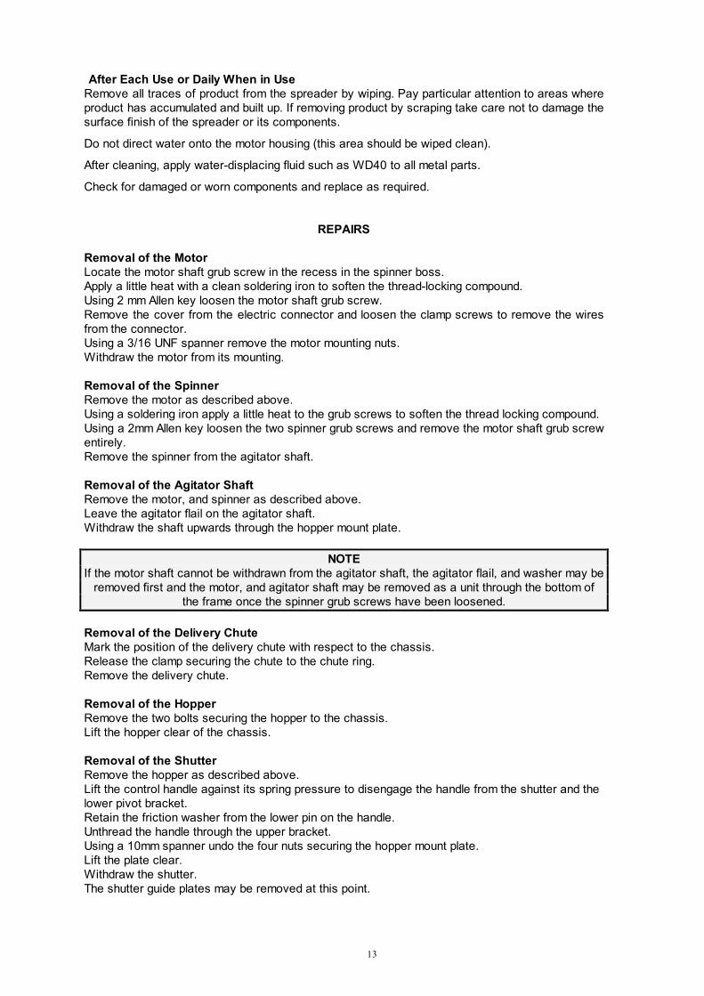
After Each Use or Daily When in Use
Remove all traces of product from the spreader by wiping. Pay particular attention to areas where
product has accumulated and built up. If removing product by scraping take care not to damage the
surface finish of the spreader or its components.
Do not direct water onto the motor housing (this area should be wiped clean).
After cleaning, apply water-displacing fluid such as WD40 to all metal parts.
Check for damaged or worn components and replace as required.
REPAIRS
Removal of the Motor
Locate the motor shaft grub screw in the recess in the spinner boss.
Apply a little heat with a clean soldering iron to soften the thread-locking compound.
Using 2 mm Allen key loosen the motor shaft grub screw.
Remove the cover from the electric connector and loosen the clamp screws to remove the wires
from the connector.
Using a 3/16 UNF spanner remove the motor mounting nuts.
Withdraw the motor from its mounting.
Removal of the Spinner
Remove the motor as described above.
Using a soldering iron apply a little heat to the grub screws to soften the thread locking compound.
Using a 2mm Allen key loosen the two spinner grub screws and remove the motor shaft grub screw
entirely.
Remove the spinner from the agitator shaft.
Removal of the Agitator Shaft
Remove the motor, and spinner as described above.
Leave the agitator flail on the agitator shaft.
Withdraw the shaft upwards through the hopper mount plate.
NOTE
If the motor shaft cannot be withdrawn from the agitator shaft, the agitator flail, and washer may be
removed first and the motor, and agitator shaft may be removed as a unit through the bottom of
the frame once the spinner grub screws have been loosened.
Removal of the Delivery Chute
Mark the position of the delivery chute with respect to the chassis.
Release the clamp securing the chute to the chute ring.
Remove the delivery chute.
Removal of the Hopper
Remove the two bolts securing the hopper to the chassis.
Lift the hopper clear of the chassis.
Removal of the Shutter
Remove the hopper as described above.
Lift the control handle against its spring pressure to disengage the handle from the shutter and the
lower pivot bracket.
Retain the friction washer from the lower pin on the handle.
Unthread the handle through the upper bracket.
Using a 10mm spanner undo the four nuts securing the hopper mount plate.
Lift the plate clear.
Withdraw the shutter.
The shutter guide plates may be removed at this point.

14
Reassembly
The above procedures may be reversed to reassemble the spreader.
Ensure that the friction washer is in place when reassembling the shutter lever assembly to the
frame.
When the delivery chute is installed it must be fixed in the same position as the original.
When the spinner has been installed the clearance between the spinner and the delivery chute
must be set to a maximum of 2.5mm.
Installing a New Agitator Flail
The flail assembly comes complete with retaining clips. Insert the new flail though the hole in the
agitator shaft.
Thread on the retaining clip so that the flail is held securely.
Using a pair of pliers, crush the clip onto the flail.
Ensure that the new flail cannot contact the wall of the hopper. Trim to length if required.
TROUBLE SHOOTING
Spinner does not turn when the switch is turned on
Wiring not connected - Check connections
Fuse has blown - Check fuse
Product has jammed agitator - Empty hopper and clear
Delivery chute touching spinner - Adjust clearance gap
Product jamming spinner - Check shutter is closed and clear product
- Check the chute clearance gap to 2.5mm
Fuse blows each time the spreader is operated
Spinner jammed - Check spinner/chute clearance gap, set to 2.5mm
Product compacted around agitator - Remove compacted product or spin the
spinner by hand before applying power
Application Rate too high - Increase the choke setting
Wiring is damaged - Check and repair as required
Excessive load on motor - Check agitator configuration
- Check product is not clogged in base of hopper
WARNING
To avoid serious damage to the motor and wiring, never replace the fuse with one rated higher
than 20 Amps.
Spinner is running, the shutter is open, but there is no product being spread
No product in hopper -Turn off and fill hopper
Product is bridging across orifice - Empty hopper and fill with fresh product
Choke is shut or adjusted too high - Correctly calibrate choke
Shutter lever won’t stay in position
Shutter friction incorrect - Check that the friction washer is correctly
located between the lower lever arm and the
lower bracket on the frame.
Product spread is uneven
The delivery chute is too far to
one side - Adjust the chute to achieve even spread
Product build up in delivery chute - Clean product off spreader

15
Product throws forward
Product escaping from delivery chute - Check chute/spinner clearance gap, set to 2.5mm
Spread pattern centred incorrectly - Adjust spread pattern centering
- 16 -
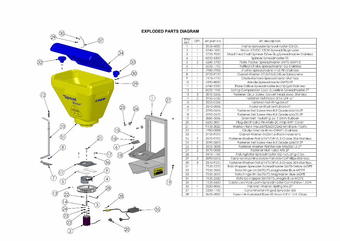
EXPLODED PARTS DIAGRAM

- 17 -
NOTES