c-dit300 - c-dax australiaau.c-dax.co.nz/files/resources/manuals/2400-5600-14 cdit300.pdf ·...
TRANSCRIPT

OWNER’S MANUAL
FOR THE
GROUND DRIVEN SPREADER
C-DIT300
C-Dax Ltd PO Box 1010, 145 Harts Road
Tiritea, Palmerston North Ph:06 354 6060 Fax:06 355 3199
E-Mail: [email protected] www.c-dax.co.nz

2
SAFETY PRECAUTIONS
CDIT300
AN IMPORTANT MESSAGE FOR OWNERS & OPERATORS OF C-Dax ATTACHMENTS/ACCESSORIES
Be warned of the dangers of loading your ATV or other vehicle in excess of its carrying capacity.
It is important to understand that any loads or attachments whether fastened to or placed on a vehicle or ATV will alter the stability or handling characteristics of that vehicle or ATV.
Spray tanks or other equipment must be filled only to a level where the gross weight is within the load limit of the ATV or other vehicle.
Safety is a primary concern in the design, manufacture, sale, and use of spray tanks and other equipment. As manufacturers of spray tanks and other equipment we want to confirm to you, our customers, our concern for safety. We take this opportunity to remind you about the simple, basic and common sense rules of safety
when using spray tanks and other equipment. Failure to follow these rules can result in severe injury or death to operators and bystanders.
It is essential that everyone involved in the assembly, operation, transport, maintenance and storage of this
equipment be aware, concerned, prudent and properly trained in safety.
This also applies to equipment that is loaned or rented to someone who has not read the owner’s manual and is not familiar with the operation of application equipment.
• NEVER EXCEED THE LOAD LIMIT CAPACITY OF THE ATV OR OTHER VEHICLE.
• ALL ATV AND TRAILED EQUIPMENT TYRES SHOULD BE INFLATED TO MANUFACTURERS RECOMMENDED OPERATING PRESSURES.
• PLEASE NOTE THAT FILLING THE SPRAY TANK OR OTHER EQUIPMENT COMPLETELY AND OR THE ATTACHMENT OF ADDITIONAL EQUIPMENT TO THE ATV MAY EXCEED THE ATV’S MAXIMUM LOAD CAPACITY, AND ADVERSELY AFFECT THE STABILITY OF THE ATV OR OTHER VEHICLE.
• CARGO SHOULD BE PROPERLY DISTRIBUTED AND SECURELY ATTACHED.
• REDUCE SPEED WHEN CARRYING CARGO OR PULLING A TRAILER OR TRAILED APPLICATION EQUIPMENT AND ALLOW GREATER DISTANCE FOR BRAKING.
• NEVER ALLOW ANYONE TO RIDE ON YOUR SPRAYER OR OTHER EQUIPMENT.
• ALWAYS FOLLOW THE INSTRUCTIONS IN THE OWNER’S VEHICLE MANUAL FOR CARRYING CARGO OR PULLING A TRAILER.
• PROPER MAINTENANCE IN LINE WITH MANUFACTURER’S RECOMMENDED MAINTENANCE PROCEDURES IS ESSENTIAL.
• BEFORE APPLYING CHEMICALS, READ THE LABEL OF THE CHEMICAL MANUFACTURER OR SUPPLIER FOR PERSONAL PROTECTIVE EQUIPMENT AND OPERATE AS RECOMMENDED.
• THE SAFETY OF ALL CHEMICALS USED IN AGRICULTURE IS UNDER THE JURISDICTION OF A GOVERNMENT AGENCY, IE N.Z. MINISTRY FOR THE ENVIRONMENT; USA ENVIRONMENTAL PROTECTION AGENCY. FURTHER LOCAL GOVERNMENT OR STATE LAWS MAY APPLY.

3
SAFETY PRECAUTIONS
Before attempting to install or operate the equipment, read and understand the manual thoroughly. Failure to comply with this instruction constitutes improper use and will invalidate the warranty.
Throughout this manual there are highlighted text boxes containing warnings, cautions and notes. Warnings are mandatory instructions to prevent serious injury or permanent damage. Cautions are advisory instructions to ensure reliable operation of the equipment. Notes are for convenient operation
• Do not overload your spreader. The maximum permissible payload is 250 Kg.
• Never use dirty product or product with stones or lumps.
• Ensure that your towing vehicle is adequate for the task. The maximum tare weight is 350 Kg.
• If using the spreader over hilly terrain the payload should be reduced to ensure that the spreader stability is not compromised.
• Never allow anyone to ride on the spreader.
• Keep the spreader in good condition. Cleanliness and maintenance are essential for safe and trouble free operation.
• Never leave product in the hopper or store the spreader without cleaning it.
• Always make sure that all moving parts are clear of debris or excess product before putting the unit away, failure to do so may cause problems with clutch mechanism

4
C-Dax CDIT300
OWNER’S MANUAL (Pt.No.2400-5600 Issue 14 Dated 02 Dec 2010)
TABLE OF CONTENTS
2 Safety Precautions 4 Table of Contents 5 Introduction Description Specifications Order Information 6 Warranty Liability 7 Operation 8 Calibration Magnesium Oxide 9 Operating the Spreader Adjusting the Spread Pattern Fitting the Rain Cover 10 Maintenance Before Use After Each Use or Daily when in Use 10 Hints 11 Parts Diagram 12 Parts List

5
INTRODUCTION C-Dax thanks you for your purchase of an advanced spreader from C-Dax Ltd. C-Dax Ltd is committed to providing you, the farmer, with quality applicating systems.
DESCRIPTION
The C-Dax C-DIT300 is a ground-driven spreader designed for application of pelleted fertilisers. It can also be used for application of other products such as grass seed and magnesium oxide. The uniquely designed 300-litre translucent non-corrosive polyethylene hopper is specially profiled for good product flow and ease of filling. The convenient flexible polypropylene cover is easy to remove, install and store if not required. A high-quality stainless steel agitator and shutter ensures even flow of product to the spinner. A unique spinner design ensures wide, even spread of product over 180 degrees (Urea). The drive train uses high quality steel and a double sealed self-aligning bearing and heavy-duty gearbox for maximum durability. While seated, the operator has access to the control handle. This handle allows disengagement and engagement of the clutch and setting of product feed rate all in one motion. Also standard are mudguards, swivel tow-hitch and a fully shrouded polyethylene front deflector to further protect the operator from product being thrown off the spinner.
Specifications: All Models Unless Stated (Specifications subject to change without notice)
Dry Weight 75 Kg Dimensions W1430mm, H1200mm, L1700mm W1450mm (Wide wheel models) Capacity 300 litre (250Kg Urea) Drive Ground driven (single wheel) Wheels 18x950x8 Chunky turf tyres Tyre Pressure 12 PSI Clutch Lever operated mechanical clutch Control Adjustable stainless steel slide with index handle Agitator Mechanical arm, stainless steel Spinner Galvanised steel with three-position adjustable vanes Hopper Non-corrosive polyethylene, ergonomically designed for ease of filling and inspection Hopper Cover Lightweight polypropylene fabric Frame Galvanised steel Gearbox Heavy duty with double sealed bearings Gearbox oil 400ml SAE30 Axle Bearings Sealed ball races Clutch bearing Heavy-duty phosphor-bronze bush Axle grease General Purpose Application Rate 140Kg per hectare @ 10 kph (nominal, Urea) Spread width 18M (nominal, Urea @ 15 Kph) Towing speed 15 Kph (Maximum recommended) NZ UK EXPORT
Order Information Standard C-DIT300 model P/N 3003 3010

6
WARRANTY
C-Dax Ltd warrants to the original purchaser that the equipment is sold free from defects in materials and workmanship for a period of 12 months from date of retail sale (6 Months from date of retail sale for all equipment sold in the U.K.). Accordingly, C-Dax Ltd undertakes to repair the equipment, or at our option replace, without cost to the original purchaser either for materials, parts or labour, any part which within the specified warranty period from time of delivery is found to be defective. PROVIDED that the equipment has been used for normal purposes in accordance with the instructions, and has not been subject to neglect, misuse or accident, and has not been repaired, serviced or dismantled by any person other than a service agent or person authorised by C-Dax Ltd. The warranty does not extend to cover: consequential damage; repair or replacement of parts due to fair wear and tear; or damage resulting from neglect, misuse, accident or hireage. SPECIFICALLY the warranty excludes battery damage, damage arising from chemical attack, and units built to customers specifications. All goods returned to C-Dax Ltd are freight paid by the sender and if subject to a warranty claim, must be accompanied by a completed warranty claim form. Warranty claim forms are available from C-Dax dealers.
LIABILITY
The maximum liability, which is accepted by C-Dax Ltd, is limited to replacement of faulty goods only. Every care has been taken in the manufacture of our goods but because use of the goods is outside the control of the manufacturer, the end user assumes all responsibility for the use. Neither the manufacturer nor retailer shall be liable for loss or damage resulting from use. Any advice or recommendations given by C-Dax Ltd, its agents, or employees is given in good faith and based on the best information available to us. No liability or responsibility is accepted or implied as a result of any information or advice tendered by C-Dax Ltd, its agents or employees. The end user accepts all responsibility arising from that advice.

7
OPERATION
The product to be spread is placed in the hopper. When the spreader is towed forward, the right hand wheel drives through the lever operated mechanical clutch and gearbox to turn the spinner in a clockwise direction. When the control handle is in the disengage position (fully back) the clutch is disengaged and the shutter is closed. Pulling the handle forward (towards the operator) engages the clutch and rotates the shutter located at the bottom of the hopper to an open position. The size of the opening is set by a shutter stop lever, which locates into one of nine pre-set positions. An extension of the spinner boss is connected to a stainless steel agitator arm inside the bottom of the hopper. The agitator ensures that product flows continuously out of the hopper to the spinning disk. A delivery chute on the bottom of the hopper ensures that product is delivered to the correct spot of the disk so that the deflectors distribute the product over a wide angle behind and to each side of the spreader. The clutch system can be engaged or disengaged at up to 15KPH while the spreader is in motion. A fabric hopper cover with an elastic band sewn into the outer edge to grip the lip of the hopper can be fitted to prevent rain and debris from entering the hopper.
WARNING To prevent premature failure or damage to the CDIT300 clutch system, do not engage or disengage the clutch
at speeds in excess of 5 KPH.

8
CALIBRATION 1. Ensure the control handle is fully back (clutch disengaged, shutter closed). 2. To calibrate your spreader, place a measured amount of product (10 Kg) in the hopper. 3. Set the Shutter Stop Lever to the position (1-9) indicated in the Calibration Guides below. Hole position 9
(shutter fully open) is denoted by two holes vertically one above the other. 4. Tow the spreader at the desired speed and pull the control handle forward to engage the clutch and open
the shutter. 5. When the product has been exhausted, measure the distance covered and band width in metres. It is
recommended that this be done over an area where the product can be seen on the ground so that the spread width can be measured.
6. Check the application rate using the following formula:
Rate (Kg/ha) = product applied (Kg) x 10,000 distance travelled (metres) x spread width (metres).
7. Adjust either the Shutter Stop Lever or the speed of travel until the desired application rate is achieved.
NOTE Because of variations in product characteristics, speedometer calibration and driving speed, the information in
the calibration guide should be regarded as a starting point only. It is recommended that the spreader be calibrated before use.
Calibration Guide
(Average Speed 10 Kph)
Product Rate
(Kg/ha) Shutter Setting (Lever Position)
Nominal Spread (Metres)
Urea or DAP 50 4 15
Urea or DAP 75 5 15
Urea or DAP 100 6 15
Super phosphate 100 7 12
30% Potassic Super 100 8 10
Rye Grass 30 3 4
Magnesium Oxide Magnesium Oxide powder is applied at a rate determined by the number of cows to be treated. When spreading this product, calculate the weight of powder to be applied and apply this amount using shutter setting 4 or 5. Because this product may set hard if left exposed to air, it must not be stored in the machine even for a short time. Load the spreader only with the amount required to be spread and clean all traces of product from the machine after use.
9
OPERATING THE SPREADER When the spreader has been correctly calibrated, the hopper may be filled to the required level and spreading commenced. To reduce agitator damage to product and to ensure that product is not forced past the agitator shaft when towing the spreader to the area to be treated, the drive to the gearbox should be disconnected by ensuring the control lever is in the disengage position (fully back).
WARNING To prevent damage to the spreader do not tow the spreader at speeds in excess of 15 Kph.
To prevent damage to the mechanical clutch do not engage or disengage the clutch on the CDIT300 at speeds in excess of 15 KPH.
CAUTION The double roll pins present in the clutch assembly are designed to shear if subject to excessive use
(preventing greater damage to the rest of the unit). If you find these pins to continually break, engage the clutch at a slower speed.
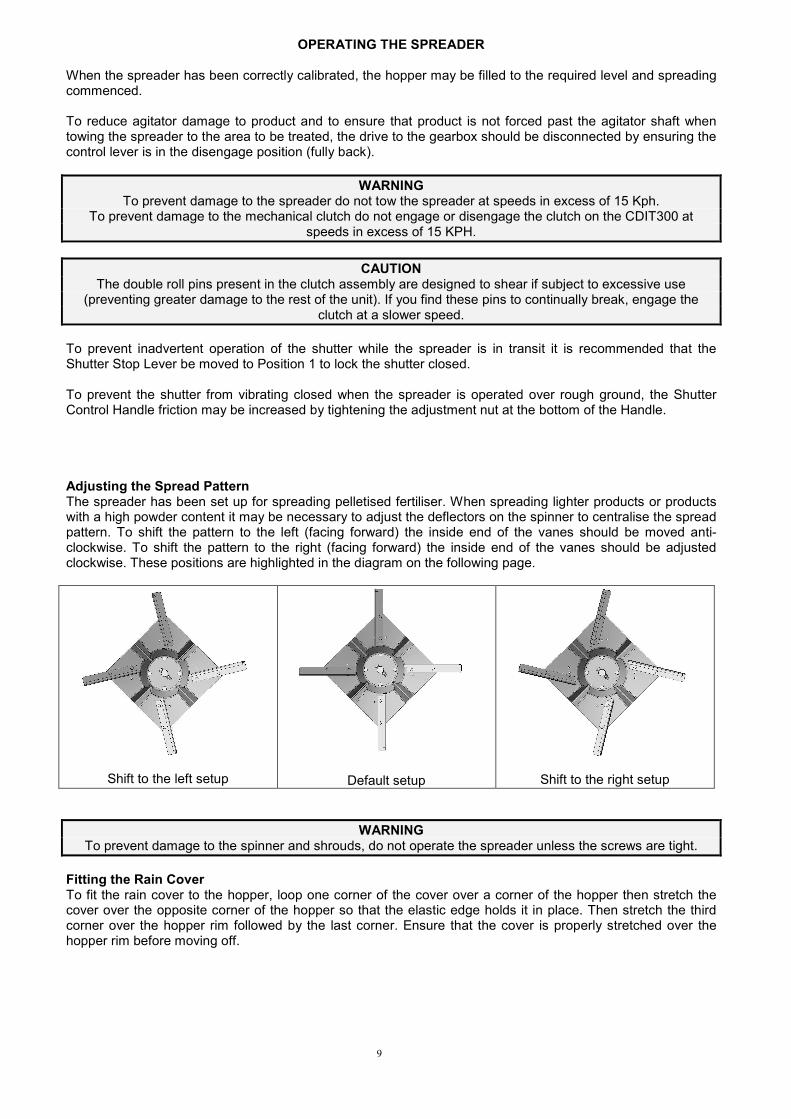
To prevent inadvertent operation of the shutter while the spreader is in transit it is recommended that the Shutter Stop Lever be moved to Position 1 to lock the shutter closed. To prevent the shutter from vibrating closed when the spreader is operated over rough ground, the Shutter Control Handle friction may be increased by tightening the adjustment nut at the bottom of the Handle. Adjusting the Spread Pattern The spreader has been set up for spreading pelletised fertiliser. When spreading lighter products or products with a high powder content it may be necessary to adjust the deflectors on the spinner to centralise the spread pattern. To shift the pattern to the left (facing forward) the inside end of the vanes should be moved anti-clockwise. To shift the pattern to the right (facing forward) the inside end of the vanes should be adjusted clockwise. These positions are highlighted in the diagram on the following page.
Shift to the left setup
Default setup
Shift to the right setup
WARNING To prevent damage to the spinner and shrouds, do not operate the spreader unless the screws are tight.
Fitting the Rain Cover To fit the rain cover to the hopper, loop one corner of the cover over a corner of the hopper then stretch the cover over the opposite corner of the hopper so that the elastic edge holds it in place. Then stretch the third corner over the hopper rim followed by the last corner. Ensure that the cover is properly stretched over the hopper rim before moving off.

10
MAINTENANCE The following maintenance actions are mandatory for reliable use of the spreader. Before Use Check the tyre pressures and charge with air as required. The correct pressure is 12 psi. (80 Kpa) Disengage the clutch by ensuring the control lever is fully back then turn the spinner by hand to ensure that it is free to turn without interference. Check the hopper to ensure that no debris is inside. If the spreader has not been used for some time, grease the bearings. Pay particular attention to the mechanical clutch engagement groove and bearing. Check the gearbox for leaks. If leaks are detected it will be necessary to drain and replenish the gearbox with 400ml of SAE 30 oil.
CAUTION To replenish the gearbox the spreader may be inverted to place the filler plug uppermost. However in doing so
extreme care must be taken to prevent damage to the spinner and deflectors.
After Each Use or Daily when in Use Remove all traces of product from the spreader by brushing or washing. Pay particular attention to areas where product has accumulated and built up. Remove by scraping if necessary taking care not to damage the surface finish of the spreader or its components. If washing do not direct high-pressure water onto the gearbox, axle or wheel bearing seals. After washing, grease the bearings (three places) and apply water displacing fluid such as WD 40 or LPS3 to all metal parts. Check for damaged or worn components and replace as required.
NOTE To ensure trouble free operation of the mechanical clutch, pay particular attention to
cleaning and greasing the drive clutch. Failure to do so will void warranty.
HINTS When greasing the pin clutch bearing in the axle assembly, leave the pin in place. This will assist the grease to fully enter the scroll in the axle and prevent the axle from being displaced if the bearing housing should be over pressurised with grease. If the drive axle is removed from the axle housing for any reason care must be taken to ensure that both the axle scroll and bronze bush are clean and free of debris before reassembly. To remove the agitator from the hopper, remove the bolt, which attaches the agitator shaft to the spinner flange assembly then withdraw the agitator from inside the hopper. When ordering replacement parts always quote the Part Number of the required part. The mechanical clutch engage/disengage bolt, which operates the clutch head is intended as a replacement item. If excessive wear is noticed, remove the bolt and replace with part number # 2890-0816.

11
PARTS DIAGRAM

12
PARTS LIST