spray g gasoline jet
TRANSCRIPT
ILASS-Americas 30th Annual Conference on Liquid Atomization and Spray Systems, Tempe, AZ, May 2019
Modeling and Detailed Numerical Simulation of the Primary Breakup of the“Spray G” Gasoline Jet
B. Zhang and Y. Ling∗
Department of Mechanical EngineeringBaylor University
Waco, TX 76798 USA
AbstractIn the present work, we model and simulate the injection and atomization of a non-reacting and non-evaporative gasoline surrogate jet by detailed numerical simulation. The nozzle geometry and operationconditions are similar to the Engine Combustion Network (ECN) “Spray G”. We focus the present studyon the primary breakup in the near field where inter-jet interaction is of secondary importance. Therefore,we have considered only one of the eight jets in the original Spray G injectors. The liquid is injected fromthe inlet into the stagnant gas chamber. A tangential velocity is added in the inlet to mimic the complexinternal flow in the original spray G injector, which leads to the plume deflection. A parametric study onthe inlet tangential velocity is carried out to identify the proper value. Simulations are performed with themultiphase flow solver Basilisk on an adaptive mesh. The gas-liquid interface is captured by the volume-of-fluid method. The model and simulation are validated by comparing the computed results of plume angle,penetration speed with experimental data. It is shown that vortices created inside the nozzle influence thenear-field primary breakup of the gasoline jet. Due to the larger Reynolds number, the near-field multiphaseflow is highly turbulent. The lambda-2 vortex identification criterion is utilized to characterize the vorticesdynamics.
∗Corresponding Author: stanley [email protected]

Introduction
The application of the direct injection in thegasoline engines play an important role in improv-ing the fuel economy and simultaneously reducingthe pollutant emission. The gasoline direct injection(GDI) system, being capable of providing accuratefuel delivery and less cycle-to-cycle variation, is criti-cal to the subsequent fuel/air mixing, spark ignition,and flame propagation in the internal engine [1].
The spray atomization is significantly influencedby the injector nozzle geometry. Yue et al. [1]showed that the machine details of the injector couldinfluence the spray development process consider-ably. Duke et al. [2] investigated the Engine Com-bustion Network (ECN) “Spray G” gasoline injector,using X-ray tomography, phase doppler interferome-try, and laser induced fluorescence by summoning upresources from multiple institutions. They mainlystudied the internal and near-nozzle flow.
Befrui et al. [3] took advantage of volume-of-fluid large-eddy-simulation (VOF-LES) method tostudy the ECN “Spray G” seat flow and the near-field primary atomization. Mitroglou et al. [4] char-acterized the performance of the multi-hole injectorsby measuring the spatial and temporal distributionsof the droplet velocity and diameter at distinct loca-tions. Aori et al. [5] investigated the effect of nozzleconfiguration on the macroscopic spray structuresof multi-hole fuel injectors under superheated con-ditions.
The liquid and vapor phases of the spray werecaptured through DBI and Schlieren imaging for theECN “Spray G” [6]. The studies of a gasoline di-rect injection multi-hole injector valve-group and thecorresponding plumes with the aid of computationalfluid dynamics methods are already performed to in-vestigate the primary breakup of a single plume [7].The effect of transient needle motion on ECN “SprayG” multi-hole injector’s internal and near nozzle flowwas studied by the homogeneous relaxation modelcoupled with the volume-of-fluid approach [8].
In spite of remarkable improvement in both ex-periments and simulations under standard “SprayG” conditions, a detailed numerical simulation ofthe spray formation of the galoline liquid jet is stilllacking. The detailed numerical simulation can offerhigh-resolution characterization of the flow field andthe spray structures.
In this work, the atomization of a gasoline jetinjected under ECN “Spray G” operating conditionis investigated by a three dimensional direct numeri-cal simulation in the near-field. One of the eight jetsin the original “Spray G” injectors is taken into ac-count for the inter-jet interaction is less important in
the near-field. The adaptive multiphase flow solverBasilisk is applied and the volume of fluid method isused to reconstruct the interface. A tangential com-ponent of the injection velocity is added in the inletto mimic the plume deflection created by the internalgeometry of the injector in ECN “Spray G” exper-iments. It is demonstrated that the flow asymme-try caused by the tangential injection velocity insidethe nozzle contributes to the generation and propa-gation of the turbulent structures in the near field.It is also revealed that the interaction between theturbulence and the interfacial waves initiates a greatnumber of small eddies produced across the jet. TheCartesian effect is ruled out by rotating the direc-tion of the tangential velocity in the inlet 45 degreeswith respect to the y axis in the simulation. More-over, the momentum conservation is studied as wellto the computation to account for the high densityratio between the liquid and the ambient gas [9].
The paper is organized as follows. In the nextsection, we present the numerical modeling and thesimulation setup. Then we present the results andthe validation of the simulation in Sec. 3.
Numerical Modeling and Simulation Setup
Governing Equations
The one-fluid approach is employed to resolvethe two-phase flow, where the phases correspondingto the fuel and the ambient air are treated as onefluid with material properties that change abruptlyacross the interface. The incompressible, variable-density, Navier-Stokes equations with surface ten-sion can be written as
ρ(∂tu + u · ∇u) = −∇p+∇ · (2µD) + σκδsn , (1)
∇ · u = 0 , (2)
where ρ, µ, u, and p represent density and viscos-ity, velocity and pressure, respectively. The defor-mation tensor is denoted by D with componentsDij = (∂iuj + ∂jui)/2. The third term on the righthand side of Eq. (1) is a singular term, with a Diracdistribution function δs localized on the interface,and it represents the surface tension force. The sur-face tension coefficient is σ, and κ and n are the localcurvature and unit normal of the interface.
The volume fraction C is introduced to distin-guish the different phases, in particular C = 1 inthe computational cells with only the ambient air(respectively C = 0 in the fuel), and its time evolu-tion satisfies the advection equation
∂tC + u · ∇C = 0 . (3)
2

The fluid density and viscosity are then defined by
ρ = Cρa + (1− C)ρl , (4)
µ = Cµa + (1− C)µl . (5)
where the subscripts a and w represent the ambientair and the fuel respectively.
Numerical Methods
The Navier-Stokes equations (Eqs. (1) and (2))are solved by a novel adaptive multiphase solverBasilisk [10]. In Basilisk, the interface between thedifferent fluids are tracked using a Volume-of-Fluid(VOF) method [11, 12]. A quad/octree spatial dis-cretisation is used, which gives a very important flex-ibility allowing dynamic grid refinement into user-defined regions. Finally the height-function (HF)method is utilized to calculate the local interfacecurvature, and a balanced-force surface tension dis-cretization is used [13, 14].
! !
!"#$%&'()) *($
!+,-.#/'+/#
0--#/&"+)#
Figure 1. Geometry of the Spray “G” nozzle andthe simulation region.
Modeling and Simulation Setup
The geometry of the Spray “G” nozzle is shownin Fig. 1, where the region enclosed by the greenrectangle is our interest of simulation. Due to theinternal geometry of the nozzle, the tangential com-ponents of the injection velocity are created whenthe jet exits from the inner hole. In order to mimicthis flow characteristic, we add a tangential compo-nent of the injection velocity along the positive ydirection in simulation. In the simulation setup, thefuel is injected into a cubic domain filled with stag-
nant nitrogen gas along the x direction from the leftboundary. A large simulation domain is used for thisstudy owing to the octree discretization of Basilisksuch that the effects of boundaries to the atomiz-ing jet are negligible. The computational domainfor the atomizing jet is shown in Fig. 2. The fluidsproperties and the injection conditions are chosenbased on the Argonne X-ray experiments, where alow-volatility gasoline surrogate with a cerium con-trast agent is used [2], see Table 1. Due to the lowvapor pressure in the chamber and the use of low-volatility liquid, evaporation can be ignored in thepresent simulation. In the numerical method we ig-nore the internal geometry of the “Spray G” nozzle.A tangential velocity along the positive y directionis then added to the inflow velocity to mimic thedeflection of the plume relative to the nozzle axis.The outflow boundary condition is invoked at theright boundary. All the rest boundaries of the do-main are then taken as symmetric boundaries. Theedge length of the domain is 64 Rinj , where Rinj isthe inner nozzle radius. The minimum cell size ofthe adaptive mesh used is indicated by ∆min, whichis equal to 5.4 µm. A snapshot of the atomizing jetand the corresponding adaptive mesh are shown inFig. 2. It is easily seen that high mesh resolutionis used to resolve the liquid-gas interface while themesh away from the jet is coarsen to decrease com-putational costs. The total number of cells increasesin time as more liquid is injected into the domain.The mesh shown in Fig. 2, which is a snapshot cor-responding to tUinj/Rinj = 23, consist of about 16million cells. The liquid normal injection velocityUinj/Rinj = 89 m/s used in the present study isidentical to that used in the standard “Spray G”operating conditions.
Results
Evolution of the Gasoline Jet
Following the experiments of Duke et al. [2],the gas in the chamber is nitrogen, with a pres-sure and temperature of 3.15 bar and 298 K, re-spectively. The density and viscosity of the gas are3.6 kg/m3 and 1.77 × 10⁻⁵ Pa s, respectively. Ifthe gas density, the jet radius, and the injectionvelocity are chosen to be reference scales, the keydimensionless parameters can be calculated, see Ta-ble 2. The Reynolds and Weber numbers of the liq-uid jet are defined as Rel = ρl(2Rinj)Uinj/µl andWel = ρl(2Rinj)U
2inj/σ, respectively, which charac-
terize the inertial effect compared to the viscous andsurface tension forces. When Rel and Wel are large,the viscous and surface tension forces are insufficientto hold the injected fuel as a bulk liquid, resulting
3

� �
��� ����������
�������
�����
�����
�
��������
Figure 2. Simulation setup for an atomizing gasoline jet (a) and the adaptive mesh utilized (b).
Fuel gasoline calibration fluid
Density ρl 838 kg/m3
Viscosity µl 9.64× 10⁻⁴ Pa sSurface tension σ 0.0278 N/mJet radius Rinj 8.65× 10⁻⁵ m
Normal injection velocity Uinj 89 m/sTangential injection velocity Vinj 0, 17.8, 35.6 m/s
Ambient gas N2
Density ρg 3.6 kg/m3
Viscosity µg 1.77× 10⁻⁵ Pa s
Table 1. Fuel properties and injection parameters.
4

! !
.123455&µ67#8
.19:49;&µ67<8
.124==&µ6
.1;;4>>&µ6
.1;5433&µ6
7(8
7'8
7$8
Figure 3. Evolution and disintegration of the gasoline jet.
5
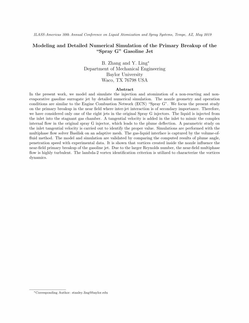
Reg Rel Wel r3.13× 103 1.34× 10⁴ 4.13× 10⁴ 2.33× 10²
Table 2. Key dimensionless parameters.
in atomization of the liquid jet into smaller droplets.As the gas flow is generated by the injected liquid inthe chamber, the Reynolds number in terms of thegas properties, Reg = ρg(2Rinj)Uinj/µg, is utilizedto measure the induced gas flow. When Reg is bigenough the gas flow can become turbulent. Finally,the liquid-to-gas density ratio is represented by rwith r = ρl/ρg. Other dimensionless parameterscan be computed based on these four parameters,for example, the liquid-to-gas viscosity ratio is equalto rReg/Rel.
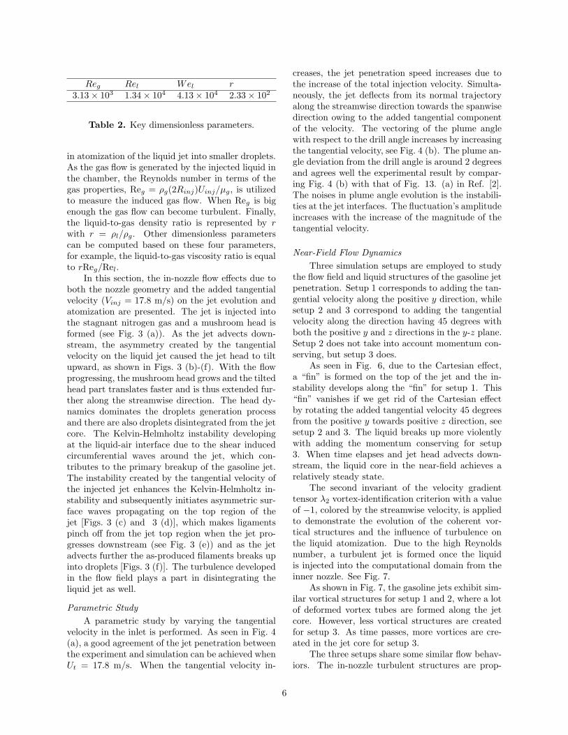
In this section, the in-nozzle flow effects due toboth the nozzle geometry and the added tangentialvelocity (Vinj = 17.8 m/s) on the jet evolution andatomization are presented. The jet is injected intothe stagnant nitrogen gas and a mushroom head isformed (see Fig. 3 (a)). As the jet advects down-stream, the asymmetry created by the tangentialvelocity on the liquid jet caused the jet head to tiltupward, as shown in Figs. 3 (b)-(f). With the flowprogressing, the mushroom head grows and the tiltedhead part translates faster and is thus extended fur-ther along the streamwise direction. The head dy-namics dominates the droplets generation processand there are also droplets disintegrated from the jetcore. The Kelvin-Helmholtz instability developingat the liquid-air interface due to the shear inducedcircumferential waves around the jet, which con-tributes to the primary breakup of the gasoline jet.The instability created by the tangential velocity ofthe injected jet enhances the Kelvin-Helmholtz in-stability and subsequently initiates asymmetric sur-face waves propagating on the top region of thejet [Figs. 3 (c) and 3 (d)], which makes ligamentspinch off from the jet top region when the jet pro-gresses downstream (see Fig. 3 (e)) and as the jetadvects further the as-produced filaments breaks upinto droplets [Figs. 3 (f)]. The turbulence developedin the flow field plays a part in disintegrating theliquid jet as well.
Parametric Study
A parametric study by varying the tangentialvelocity in the inlet is performed. As seen in Fig. 4(a), a good agreement of the jet penetration betweenthe experiment and simulation can be achieved whenUt = 17.8 m/s. When the tangential velocity in-
creases, the jet penetration speed increases due tothe increase of the total injection velocity. Simulta-neously, the jet deflects from its normal trajectoryalong the streamwise direction towards the spanwisedirection owing to the added tangential componentof the velocity. The vectoring of the plume anglewith respect to the drill angle increases by increasingthe tangential velocity, see Fig. 4 (b). The plume an-gle deviation from the drill angle is around 2 degreesand agrees well the experimental result by compar-ing Fig. 4 (b) with that of Fig. 13. (a) in Ref. [2].The noises in plume angle evolution is the instabili-ties at the jet interfaces. The fluctuation’s amplitudeincreases with the increase of the magnitude of thetangential velocity.
Near-Field Flow Dynamics
Three simulation setups are employed to studythe flow field and liquid structures of the gasoline jetpenetration. Setup 1 corresponds to adding the tan-gential velocity along the positive y direction, whilesetup 2 and 3 correspond to adding the tangentialvelocity along the direction having 45 degrees withboth the positive y and z directions in the y-z plane.Setup 2 does not take into account momentum con-serving, but setup 3 does.
As seen in Fig. 6, due to the Cartesian effect,a “fin” is formed on the top of the jet and the in-stability develops along the “fin” for setup 1. This“fin” vanishes if we get rid of the Cartesian effectby rotating the added tangential velocity 45 degreesfrom the positive y towards positive z direction, seesetup 2 and 3. The liquid breaks up more violentlywith adding the momentum conserving for setup3. When time elapses and jet head advects down-stream, the liquid core in the near-field achieves arelatively steady state.
The second invariant of the velocity gradienttensor λ2 vortex-identification criterion with a valueof −1, colored by the streamwise velocity, is appliedto demonstrate the evolution of the coherent vor-tical structures and the influence of turbulence onthe liquid atomization. Due to the high Reynoldsnumber, a turbulent jet is formed once the liquidis injected into the computational domain from theinner nozzle. See Fig. 7.
As shown in Fig. 7, the gasoline jets exhibit sim-ilar vortical structures for setup 1 and 2, where a lotof deformed vortex tubes are formed along the jetcore. However, less vortical structures are createdfor setup 3. As time passes, more vortices are cre-ated in the jet core for setup 3.
The three setups share some similar flow behav-iors. The in-nozzle turbulent structures are prop-
6

! !
!"#!$#
%$&'()*+)(,-(./0(&1$2)-230()$&'2()4(5/$1/*&
Figure 4. Gasoline liquid jet penetration measured from the present simulation with distinct tangentialvelocities and previous experimental work of Ref. [2] (a) and the plume angle deviation from the drill angle(b).
! !
!"#
$%&'()*+)(,-(./0(&1%2)-230()%&'2()4(5/%1/*&
!%#
Figure 5. Gasoline liquid jet penetration measured from the present simulation with distinct tangentialvelocities and previous experimental work of Ref. [2] (a) and the plume angle deviation from the drill angle(b).
7

! !
16789:)µ;
16<78=>)µ;
?/4(@);(13-)<
?/4(@);(13-)<
A*-@);(13-)<
A*-@);(13-)<
B*11*0@);(13-)<
B*11*0@);(13-)<
?/4(@);(13-):
?/4(@);(13-):
A*-@);(13-):
A*-@);(13-):
B*11*0@);(13-):
B*11*0@);(13-):
?/4(@);(13-)>
?/4(@);(13-)>
A*-@);(13-)>
A*-@);(13-)>
B*11*0@);(13-)>
B*11*0@);(13-)>
Figure 6. Comparing the evolution of the volume of fluid isosurfaces from different views for the gasolineliquid jet penetration with three distinct setups.
8

! !
!"#$%&'µ(
!")#$*+'µ(
,-./0'(/!12')
,-./0'(/!12')
3420'(/!12')
3420'(/!12')
54!!460'(/!12')
54!!460'(/!12')
,-./0'(/!12'+
,-./0'(/!12'+
3420'(/!12'+
3420'(/!12'+
54!!460'(/!12'+
54!!460'(/!12'+
,-./0'(/!12'&
,-./0'(/!12'&
3420'(/!12'&
3420'(/!12'&
54!!460'(/!12'&
54!!460'(/!12'&
Figure 7. Comparing the evolution of the lambda-2 isosurfaces colored by the streamwise velocity magnitudefrom different views for the gasoline liquid jet penetration with three distinct setups.
9

! !
!"#$%$&'µ( )$%#*'µ(' &&%&)'µ( $&%+&'µ(,-. ,/. ,0. ,1.
,2. ,3. ,4. ,5.
Figure 8. Evolution of droplet size distribution for setup 2 (a-d) and setup 3 (e-h).
agated away from the nozzle and interact with theinterfacial Kelvin-Helmholtz waves, enhancing theinterfacial disturbances and contributing to the jetatomization. The ambient gas is entrained into thecounterbore due to the lower pressure created insidethe counterbore, which is induced by the fast flow-ing liquid. Simultaneously, the azimuthal asymme-try created by the tangential velocity caused furtherentrainment of the surrounding gas into the bottomwall of the inner-nozzle, which shifts the jet upwardsand induces a flow constriction and a further nar-rowed jet. The entrainment of the gas into the nozzlegenerates more vortices subsequently.
The longitudinal vortical structures are formedalong the jet core and stretched by the pull of thestrong interfacial aerodynamic force. As the flowprogresses, more vortices are generated in the near-field owing to the turbulent jet and the turbulence inthe moving gas induced by the disturbing jet. Thespanwise vortical structures are developed close tothe jet head. Furthermore, the hairpin vortices arecreated from the jet head and are pulled by the gasand flow backward along the longitudinal direction.As the jet advects further downstream, more tur-bulent structures are produced close to the jet andspread up from the jet region into the gas.
Drop Statistics
Fig. 8 shows the temporal evolution of the dis-tribution of droplet number over the droplet volume-based diameter for setup 2 and 3. Figs. 8 (a)-(d) and
(e)-(h) indicate that more droplets are generated forsetup 3 at each stage. For both cases, the domi-nant droplet size is 6.7 µm and in this simulationthe droplets with a diameter less than 6.7 µm havebeen removed during simulation. The linear rela-tions in all plots indicate that the droplet sizes obeyan exponential distribution for both setup 2 and 3at different time.
Conclusions
The penetration and atomization of a gasolineliquid jet are investigated in the near-field in thepresent work. A parametric study based on varyingthe tangential component of the injecting velocityis performed initially to mimic the deflection of thefuel plume from the nozzle axis in the experimentsunder “Spray G” conditions, which gives a reason-able tangential velocity. The simulated penetrationand vectoring of the plume are found to agree wellwith the Argonne X-ray experiments. Furthermore,the low-volatility of the gasoline surrogate utilizedin Argonne X-ray experiments validates the appli-cation of the current code without considering thevapor phase.
Three distinct setups are considered and the mo-mentum conserving code is used.
The in-nozzle turbulence enhances the disinte-gration of the liquid jet and contributes to the frag-mentation of the liquid filaments by the propagationof the induced disturbances along the jet. The hair-pin vortices are easily distinguished and the evolu-
10

tion of the vortical structures can be convenientlytraced with the application of the λ2 vortex identi-fication criterion.
The drop statistics is studied, which reveals thatthe drop size distribution follows an exponential law.
Acknowledgements
This work was supported by Baylor University.The simulations were performed on the Baylor clus-ter Kodiak and Texas Advanced Computing Centercluster TACC.
References
[1] Z. Yue, M. Battistoni, and S. Som. FourteenthInternational Conference on Liquid Atomiza-tion and Spray Systems, Chicago, IL, USA,July 2018, 2018.
[2] D. J. Duke, A. L. Kastengren, K. E. Matusik,A. B. Swantek, C. F. Powell, R. Payri, D. Va-querizo, L. Itani, G. Bruneaux, R. O. Grover Jr,S. Parrish, L. Markel, D. Schmidt, J. Manin,S. A. Skeen, and L. M. Pickett. Exp. Therm.Fluid Sci., 88:608–621, 2017.
[3] B. Befrui, A. Aye, A. Bossi, L. E. Markle, andD. L. Varble. ILASS Americas 28th AnnualConference, Dearborn (MI), USA, pp. 304–316,2016.
[4] N. Mitroglou, J. M. Nouri, Y. Yan, M. Gavaises,and C. Arcoumanis. SAE Technical Paper,2007.
[5] G. Aori, D. Hung, M. Zhang, G. Zhang, andT. Li. Atomization sprays, 26(5), 2016.
[6] R. Payri, F. J. Salvador, P. Mart́ı-Aldarav́ı, andD. Vaquerizo. Appl. Therm. Eng., 112:304–316,2017.
[7] B. Befrui, G. Corbinelli, M. D’Onofrio, andD. Varble. SAE Technical Paper, 2011.
[8] B. Mohan, M. Jaasim, F. H. Perez, J. Sim,W. Roberts, and H. Im. Proceedings of the10th International Symposium on Cavitation(CAV2018), 2018.
[9] D. Fuster, M. Arrufat, T. andCrialesi-Esposito,Y. Ling, L. Malan, S. Pal, R. Scar-dovelli, G. Tryggvason, and S. Zaleski.arXiv:1811.12327, 2018.
[10] S. Popinet. The basilisk code. Available fromhttp://basilisk.fr/.
[11] R. Scardovelli and S. Zaleski. Annu. Rev. FluidMech., 31:567–603, 1999.
[12] G. Tryggvason, R. Scardovelli, and S. Zaleski.Direct numerical simulations of gas-liquid mul-tiphase flows. Cambridge University Press,2011.
[13] M. M. Francois, S. J. Cummins, E. D. Dendy,D. B. Kothe, J. M. Sicilian, and M. W.Williams. J. Comput. Phys., 213:141–173, 2006.
[14] S. Popinet. J. Comput. Phys., 228(16):5838–5866, 2009.
11