speeder - liebherr
TRANSCRIPT

Wheel Loader
L 538Speeder
Generation6
Tipping load9,800 kg
EngineStage V
2 L 538 Speeder
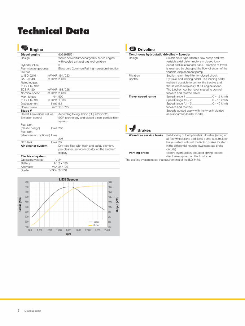
EngineDiesel engine 6068HB551Design Water-cooled turbocharged in-series engine
with cooled exhaust gas recirculationCylinder inline 6Fuel injection process Electronic Common Rail high-pressure injectionOutputto ISO 9249 ~ kW / HP SAE J1349 at RPM
164 / 2232,400
Rated outputto ISO 14396 / ECE-R.120 kW / HP
168 / 228Nominal speed at RPM 2,400Max. torque Nm to ISO 14396 at RPM
9001,600
Displacement litres 6.8Bore / Stroke mm 106 / 127Stage VHarmful emissions values According to regulation (EU) 2016/1628Emission control SCR technology and closed diesel particle filter
systemFuel tank (plastic design) litres
205
Fuel tank (steel version, optional) litres
205
DEF tank litres 20Air cleaner system Dry type filter with main and safety element,
pre-cleaner, service indicator on the Liebherr display
Electrical systemOperating voltage V 24Battery Ah 2 x 135Alternator V / A 24 / 100Starter V / kW 24 / 7.8
DrivelineContinuous hydrostatic driveline – SpeederDesign Swash plate type variable flow pump and two
variable axial piston motors in closed loop circuit and axle transfer case. Direction of travel is reversed by changing the flow-direction of the variable-displacement pump
Filtration Suction return line filter for closed circuitControl By travel and inching pedal. The inching pedal
makes it possible to control the tractive and thrust forces steplessly at full engine speed. The Liebherr control lever is used to control forward and reverse travel
Travel speed range Speed range 1 _________________________ 0 – 8 km/hSpeed range A1 – 2 ___________________ 0 – 16 km/hSpeed range A1 – 3 ___________________ 0 – 40 km/hforward and reverse Speeds quoted apply with the tyres indicated as standard on loader model.
Technical Data
Outp
ut (k
W)
45500
600
550
650
700
750
800
850
950
900
60
90
75
120
105
135
150
165
180
Torq
ue (N
m)
1,200800 1,000 1,400 1,600 1,800 2,000 2,200 2,400
rpm
TorqueOutput
24.04.2020
L 538 Speeder
BrakesWear-free service brake Self-locking of the hydrostatic driveline (acting on
all four wheels) and additional pump-accumulator brake system with wet multi-disc brakes located in the differential housing (two separate brake circuits)
Parking brake Electro-hydraulically actuated spring-loaded disc brake system on the front axle
The braking system meets the requirements of the ISO 3450.

L 538 Speeder 3
CapacitiesEngine oil (inclusive filter change) l
18
Transmission l 2.5Coolant l 26.5Front axle / wheel hubs l 19 / 3.5Rear axle / wheel hubs l 19 / 3.5Hydraulic tank l 95Hydraulic system, total l 180
AxlesFour-wheel driveFront axle FixedRear axle Centre pivot, with 10° oscillating angle to each
sideHeight of obstacles which can be driven over mm
470with all four wheels remaining in contact with the ground
Differentials Automatic limited-slip differentials with 45 % locking action in both axles
Reduction gear Planetary final drive in wheel hubsTrack width 1,900 mm with all types of tyres
Attachment HydraulicsDesign “Load-sensing” variable axial piston pump with
output and flow control, and pressure cut-off in the control block
Cooling Hydraulic oil cooling using thermostatically controlled fan and oil cooler
Filtration Return line filter in the hydraulic reservoirControl Liebherr control lever, electro-hydraulically
operatedLifting function Lifting, neutral, lowering
Float position controlled by Liebherr control lever with detent
Tilt function Tilt back, neutral, dumpAutomatic bucket return to dig
Max. flow l/min. 228Max. pressureZ-bar linkage bar 350Parallel linkage bar 350
AttachmentGeometry variantsOptional Powerful Z-bar linkage with tilt cylinder, hydraulic
quick hitch optionalParallel linkage with two tilt cylinders, hydraulic quick hitch as standard
Bearings SealedCycle time at nominal load
ZK
PK
Lifting s 5.7 5.7Dumping s 2.9 4.3Lowering (empty) s 4.7 4.7
Sound LevelSound pressure level to ISO 6396LpA (inside cab) dB(A) 69Sound power level to 2000/14/ECLWA (surround noise) dB(A) 104
SteeringDesign “Load-sensing” swash plate type variable flow
pump with pressure cut-off and flow control. Central pivot with two double-acting steering cylinders
Angle of articulation 40° to each sideEmergency steering Electro-hydraulic emergency steering system
Operator’s CabDesign Elastic mounted, noise-proof cab
ROPS roll over protection per EN ISO 3471 / EN 474-1FOPS falling objects protection per EN ISO 3449 / EN 474-1, Cat. IIComfort safety door with 180° opening angle with rigid window, right side sliding side window, front windscreen made of laminated safety glass, green tinted as standard, side panels with single-pane safety glass ESG, green tinted, heated rear window ESG. Continuously adjustable steering column
Liebherr operator’s seat 6 way adjustable, vibration-damped operator’s seat “Comfort” with seat, depth and incline adjustment as standard (air-cushioned with seat heating adjustable to operator’s weight), Liebherr control lever mounted into the operator’s seat as standard
Cab heating and ventilation
2-level air control, cooling water heating, defroster and air conditioning via manual nozzle position or electronic valve control for head and front area, as well as electronic fresh / recirculated air control, electrically heated rear window, filter system with pre-filter, fresh air filter and recirculated air filter, easily replaced, air condition / automatic air conditioning system with new improved cooling output optional
4 L 538 Speeder
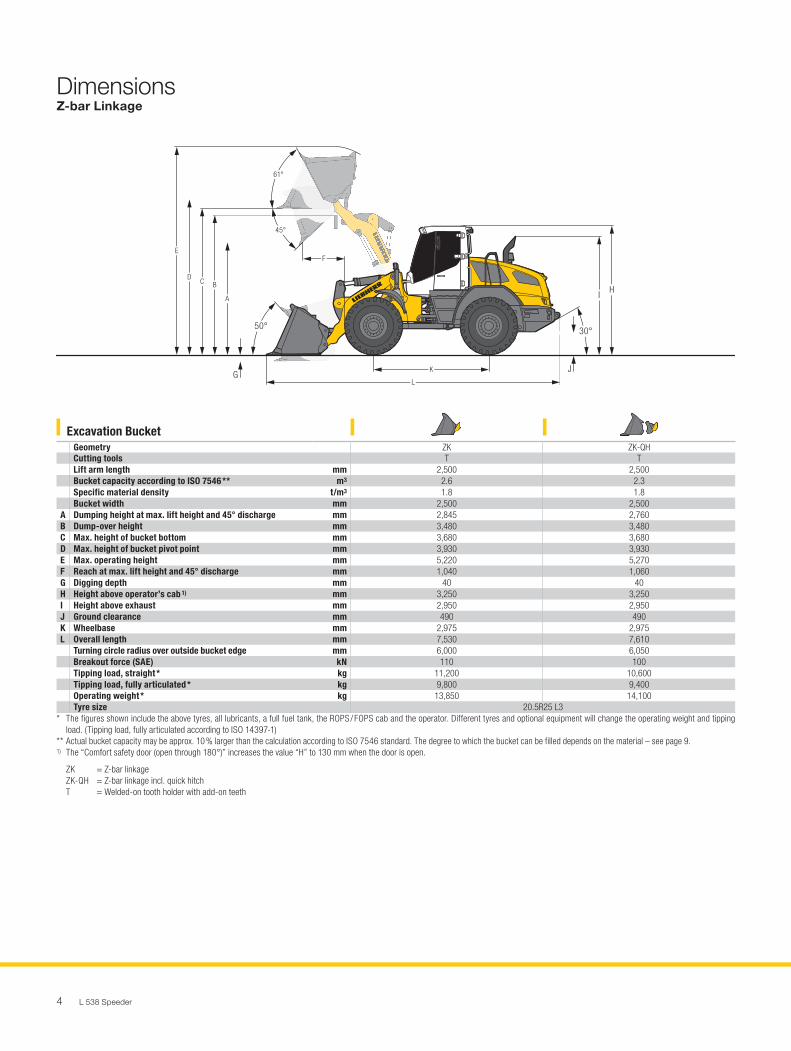
Excavation BucketGeometry ZK ZK-QHCutting tools T TLift arm length mm 2,500 2,500Bucket capacity according to ISO 7546 ** m3 2.6 2.3Specific material density t/m3 1.8 1.8Bucket width mm 2,500 2,500
A Dumping height at max. lift height and 45° discharge mm 2,845 2,760B Dump-over height mm 3,480 3,480C Max. height of bucket bottom mm 3,680 3,680D Max. height of bucket pivot point mm 3,930 3,930E Max. operating height mm 5,220 5,270F Reach at max. lift height and 45° discharge mm 1,040 1,060G Digging depth mm 40 40H Height above operator’s cab 1) mm 3,250 3,250I Height above exhaust mm 2,950 2,950J Ground clearance mm 490 490K Wheelbase mm 2,975 2,975L Overall length mm 7,530 7,610
Turning circle radius over outside bucket edge mm 6,000 6,050Breakout force (SAE) kN 110 100Tipping load, straight * kg 11,200 10,600Tipping load, fully articulated * kg 9,800 9,400Operating weight * kg 13,850 14,100Tyre size 20.5R25 L3
* The figures shown include the above tyres, all lubricants, a full fuel tank, the ROPS / FOPS cab and the operator. Different tyres and optional equipment will change the operating weight and tipping load. (Tipping load, fully articulated according to ISO 14397-1)
** Actual bucket capacity may be approx. 10 % larger than the calculation according to ISO 7546 standard. The degree to which the bucket can be filled depends on the material – see page 9.1) The “Comfort safety door (open through 180°)” increases the value “H” to 130 mm when the door is open.
ZK = Z-bar linkage ZK-QH = Z-bar linkage incl. quick hitch T = Welded-on tooth holder with add-on teeth
J
I H
G
50° 30°
E
DC B
A
K
L
F
45°
61°
L0289
DimensionsZ-bar Linkage

L 538 Speeder 5
Excavation BucketSTD HL
Geometry PK-QH PK-QHCutting tools T TLift arm length mm 2,570 3,000Bucket capacity according to ISO 7546 ** m3 2.3 2.3Specific material density t/m3 1.8 1.5Bucket width mm 2,500 2,500
A Dumping height at max. lift height and 45° discharge mm 2,790 3,350B Dump-over height mm 3,480 4,040C Max. height of bucket bottom mm 3,680 4,260D Max. height of bucket pivot point mm 3,930 4,510E Max. operating height mm 5,290 5,860F Reach at max. lift height and 45° discharge mm 1,110 1,030G Digging depth mm 55 25H Height above operator’s cab 1) mm 3,250 3,250I Height above exhaust mm 2,950 2,950J Ground clearance mm 490 490K Wheelbase mm 2,975 2,975L Overall length mm 7,720 8,260
Turning circle radius over outside bucket edge mm 6,090 6,370Breakout force (SAE) kN 108 108Tipping load, straight * kg 10,500 8,600Tipping load, fully articulated * kg 9,300 7,600Operating weight * kg 14,100 14,350Tyre size 20.5R25 L3
* The figures shown include the above tyres, all lubricants, a full fuel tank, the ROPS / FOPS cab and the operator. Different tyres and optional equipment will change the operating weight and tipping load. (Tipping load, fully articulated according to ISO 14397-1)
** Actual bucket capacity may be approx. 10 % larger than the calculation according to ISO 7546 standard. The degree to which the bucket can be filled depends on the material – see page 9.1) The “Comfort safety door (open through 180°)” increases the value “H” to 130 mm when the door is open.
STD = Standard lift arm length HL = High Lift PK-QH = Parallel linkage incl. quick hitch T = Welded-on tooth holder with add-on teeth
J
E
D C B
A
KL
F
I H
G
50°30°
45°
54°
L0294
DimensionsParallel Linkage

6 L 538 Speeder
Heavy Material DensitySTD HL
Geometry PK-QH PK-QHCutting tools BOCE BOCEBucket capacity m3 4.0 3.5Specific material density t/m3 1.0 1.0Bucket width mm 2,700 2,700
A Dumping height at max. lift height mm 2,490 3,140E Max. operating height mm 5,585 6,020F Reach at maximum lift height mm 1,360 1,230L Overall length mm 7,955 8,450
Tipping load, straight * kg 10,000 8,200Tipping load, fully articulated * kg 8,900 7,300Operating weight * kg 14,300 14,650Tyre size 20.5R25 L3
Light Material DensitySTD HL
Geometry PK-QH PK-QHCutting tools BOCE BOCEBucket capacity m3 6.5 5.5Specific material density t/m3 0.5 0.5Bucket width mm 2,700 2,700
A Dumping height at max. lift height mm 2,160 2,845E Max. operating height mm 5,995 6,410F Reach at maximum lift height mm 1,670 1,520L Overall length mm 8,420 8,860
Tipping load, straight * kg 9,600 7,900Tipping load, fully articulated * kg 8,500 6,900Operating weight * kg 14,880 14,950Tyre size 20.5R25 L3
* The figures shown include the above tyres, all lubricants, a full fuel tank, the ROPS / FOPS cab and the operator. Different tyres and optional equipment will change the operating weight and tipping load. (Tipping load, fully articulated according to ISO 14397-1)
STD = Standard lift arm length HL = High Lift PK-QH = Parallel linkage incl. quick hitch BOCE = Bolt-on cutting edge
L
E
A
F
L0295
AttachmentLight Material Bucket

L 538 Speeder 7
Heavy Material DensitySTD HL
Geometry PK-QH PK-QHCutting tools BOCE BOCEBucket capacity m3 3.5 3.0Specific material density t/m3 1.0 1.0Bucket width mm 2,700 2,700
A Dumping height at max. lift height mm 4,560 5,320E Max. operating height mm 6,420 6,985F Reach at maximum lift height mm 1,460 1,250L Overall length mm 8,080 8,590
Tipping load, straight * kg 9,000 7,300Tipping load, fully articulated * kg 7,900 6,500Operating weight * kg 15,130 15,290Tyre size 20.5R25 L3
Light Material DensitySTD HL
Geometry PK-QH PK-QHCutting tools BOCE BOCEBucket capacity m3 6.0 5.0Specific material density t/m3 0.5 0.5Bucket width mm 2,700 2,700
A Dumping height at max. lift height mm 4,430 5,245E Max. operating height mm 6,880 7,325F Reach at maximum lift height mm 1,700 1,460L Overall length mm 8,305 8,760
Tipping load, straight * kg 9,300 7,400Tipping load, fully articulated * kg 8,200 6,500Operating weight * kg 15,200 15,390Tyre size 20.5R25 L3
* The figures shown include the above tyres, all lubricants, a full fuel tank, the ROPS / FOPS cab and the operator. Different tyres and optional equipment will change the operating weight and tipping load. (Tipping load, fully articulated according to ISO 14397-1)
STD = Standard lift arm length HL = High Lift PK-QH = Parallel linkage incl. quick hitch BOCE = Bolt-on cutting edge
E
A
L
F
L0296
AttachmentHigh-Dump Bucket

8 L 538 Speeder
Fork Carrier and ForkFork FEM III FEM III FEM IV FEM IVGeometry ZK-QH PK-QH ZK-QH PK-QHLift arm length mm 2,500 2,570 2,500 2,570
A Lifting height at max. reach mm 1,780 1,740 1,740 1,700C Max. lifting height mm 3,740 3,740 3,700 3,705E Max. operating height mm 4,664 4,664 4,695 4,700F Reach at loading position mm 965 1,060 995 1,080F max. Max. reach mm 1,660 1,700 1,640 1,680F min. Reach at max. lifting height mm 710 735 690 715G Fork length mm 1,200 1,200 1,200 1,200L Length – basic machine mm 6,510 6,590 6,530 6,620
Tipping load, straight * kg 8,100 8,300 8,000 8,300Tipping load, fully articulated * kg 7,200 7,400 7,100 7,300Recommended payload for uneven ground = 60 % of tipping load, articulated 1)
kg 4,050 4,320 4,000 4,270
Recommended payload for smooth surfaces = 80 % of tipping load, articulated 1)
kg 5,000 3) 5,000 3) 5,200 2) 5,700
Operating weight * kg 13,600 13,600 13,850 13,850Tyre size 20.5R25 L3 20.5R25 L3
* The figures shown include the above tyres, all lubricants, a full fuel tank, the ROPS / FOPS cab and the operator. Different tyres and optional equipment will change the operating weight and tipping load. (Tipping load, fully articulated according to ISO 14397-1)
1) According to EN 474-32) Payload is limited by tilt cylinder of Z-bar linkage3) Payload is limited by FEM III fork carrier and forks to 5,000 kg
ZK-QH = Z-bar linkage incl. quick hitch PK-QH = Parallel linkage incl. quick hitch
E
C
G F
A
L
F max.
F min.FEM III (500)FEM IV (600)
L0297
AttachmentFork Carrier and Fork
L 538 Speeder 9
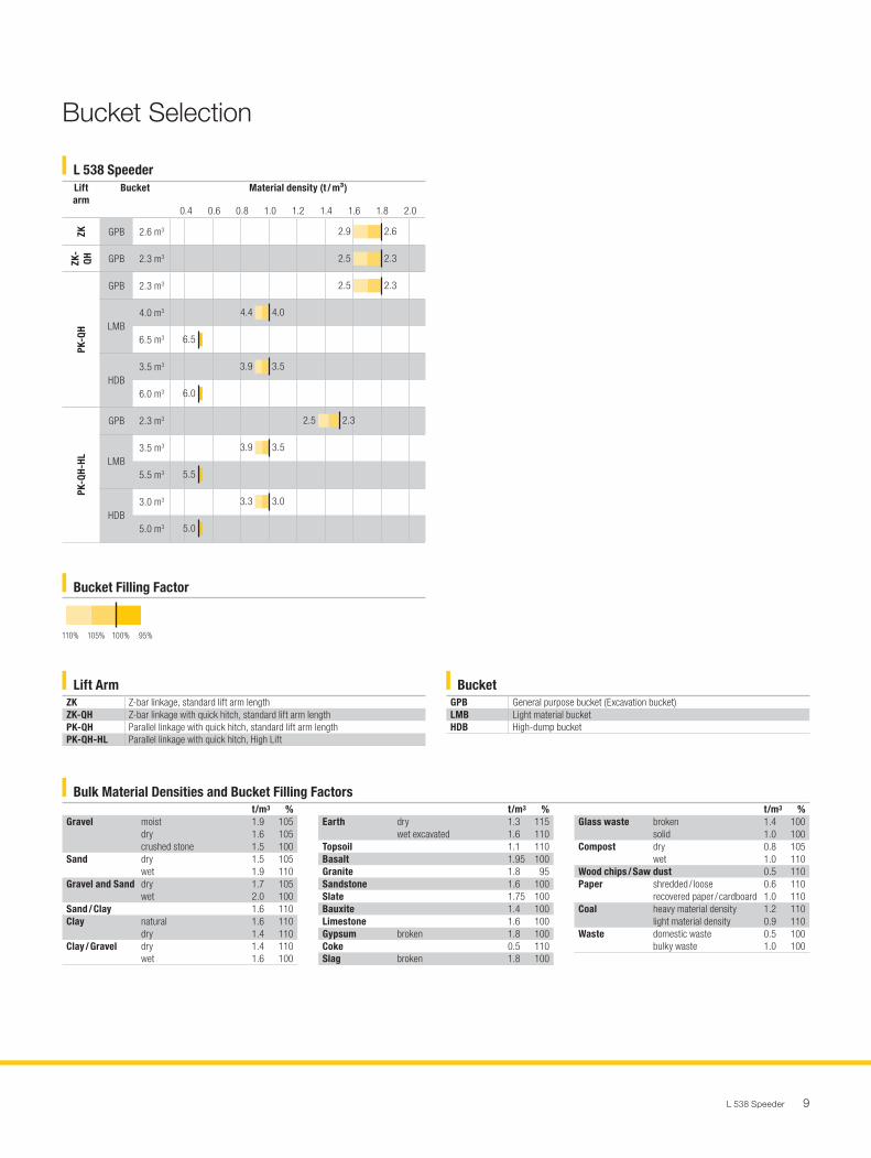
Bucket Selection
L 538 Speeder
Bucket Filling Factor
Lift ArmZK Z-bar linkage, standard lift arm lengthZK-QH Z-bar linkage with quick hitch, standard lift arm lengthPK-QH Parallel linkage with quick hitch, standard lift arm lengthPK-QH-HL Parallel linkage with quick hitch, High Lift
BucketGPB General purpose bucket (Excavation bucket)LMB Light material bucketHDB High-dump bucket
100% 95%105%110%
Bucket filling factor
t/m3 %Gravel moist 1.9 105
dry 1.6 105crushed stone 1.5 100
Sand dry 1.5 105wet 1.9 110
Gravel and Sand dry 1.7 105wet 2.0 100
Sand / Clay 1.6 110Clay natural 1.6 110
dry 1.4 110Clay / Gravel dry 1.4 110
wet 1.6 100
t/m3 %Glass waste broken 1.4 100
solid 1.0 100Compost dry 0.8 105
wet 1.0 110Wood chips / Saw dust 0.5 110Paper shredded / loose 0.6 110
recovered paper / cardboard 1.0 110Coal heavy material density 1.2 110
light material density 0.9 110Waste domestic waste 0.5 100
bulky waste 1.0 100
t/m3 %Earth dry 1.3 115
wet excavated 1.6 110Topsoil 1.1 110Basalt 1.95 100Granite 1.8 95Sandstone 1.6 100Slate 1.75 100Bauxite 1.4 100Limestone 1.6 100Gypsum broken 1.8 100Coke 0.5 110Slag broken 1.8 100
Bulk Material Densities and Bucket Filling Factors
enGB
Lift arm
Bucket Material density (t / m³)
0.4 0.6 0.8 1.0 1.2 1.4 1.6 1.8 2.0
ZK GPB 2.6 m3
ZK-
QH GPB 2.3 m3
PK-Q
H
GPB 2.3 m3
LMB4.0 m3
6.5 m3
HDB3.5 m3
6.0 m3
PK-Q
H-HL
GPB 2.3 m3
LMB3.5 m3
5.5 m3
HDB3.0 m3
5.0 m3
2.9
2.5
4.4
6.5
6.0
5.5
5.0
3.9
3.9
3.3
2.5
2.5
2.6
2.3
4.0
3.5
3.5
3.0
2.3
2.3
01.09.2020
87,5 mm breit x 87,075 mm hoch
L538-1966 Schaufelauswahltabelle LBH L0326

10 L 538 Speeder
Tyre TypesSize
and tread codeChange of
operating weight kg
Width over tyres
mm
Change in vertical dimensions *
mm
Use
L 538 SpeederBridgestone 20.5R25 VJT L3 17 2,480 8 Bulk material (firm ground conditions)Continental 20.5R25 EM-Master L3 156 2,480 26 Bulk material (firm ground conditions)Goodyear 20.5R25 TL-3A+ L3 156 2,500 11 Sand, Gravel, Earthworks, Clay (all ground conditions)Goodyear 20.5R25 RT-3B L3 11 2,490 16 Gravel (all ground conditions)Michelin 20.5R25 XTLA L2 – 121 2,510 – 7 Gravel, Earthworks, Clay (all ground conditions)Michelin 20.5R25 XHA2 L3 0 2,480 0 Sand, Gravel (all ground conditions)Michelin 620/70R26 CereXBib 2 – 364 2,620 11 Green area (agricultural tractor)Michelin 620/75R26 MegaXBib – 318 2,600 68 Green area (agricultural tractor)Michelin 750/65R26 MegaXBib – 22 2,850 81 Green area (agricultural tractor)Mitas 750/65R26 SFT – 62 2,880 76 Green area (agricultural tractor)Nokian 20.5R25 Hakkapeliitta L2 – 114 2,490 6 Winter tyres, Gravel, Asphalt (all ground conditions) Trelleborg 620/75R26 TM2000 L3 – 153 2,640 72 Green area (agricultural tractor)
* The stated values are theoretical and may deviate in practice.
Before operating the vehicle with tyre foam filling or tyre protection chains, please discuss this with the Liebherr-Werk Bischofshofen GmbH.
Tyres
The Liebherr Wheel Loaders
Wheel LoaderL 538 Speeder
Tipping load kg 9,800Bucket capacity m3 2.6Operating weight kg 13,850Engine output kW / HP 168 / 228
10.20
L0302
Tipping Load
What is tipping load?Load at centre of gravity of working equipment, so that the wheel loader just begins to tip over the front axle.This is the most unfavourable static-load position for the wheel loader. Lifting arms horizontal, wheel loader fully articulated at centre pivot.
Pay load.The pay load must not exceed 50 % of the tipping load when articulated.This is equivalent to a static stability-margin factor of 2.0.
Bucket capacity.The bucket volume is determined from the pay load.
ISO 14397-1
Pay load =Tipping load, articulated
2
Bucket capacity =Pay load (t)
Specific bulk weight of material (t/m3)
L 538 Speeder 11
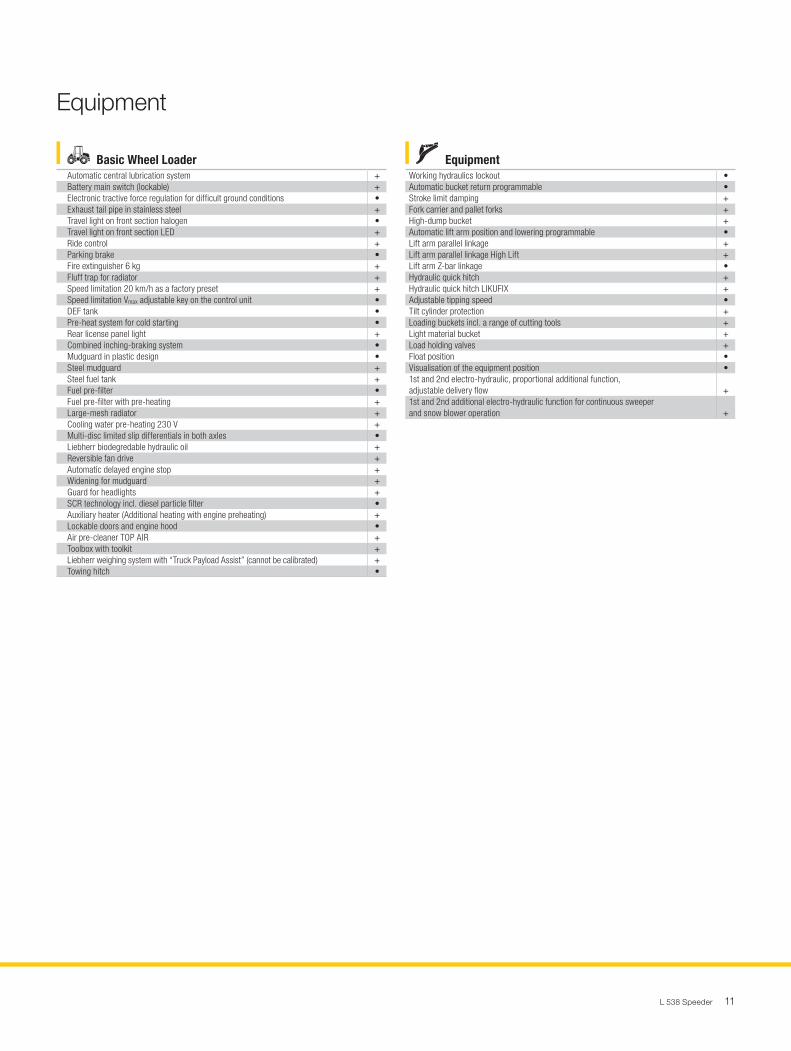
Basic Wheel LoaderAutomatic central lubrication system +Battery main switch (lockable) +Electronic tractive force regulation for difficult ground conditions •Exhaust tail pipe in stainless steel +Travel light on front section halogen •Travel light on front section LED +Ride control +Parking brake •Fire extinguisher 6 kg +Fluff trap for radiator +Speed limitation 20 km/h as a factory preset +Speed limitation Vmax adjustable key on the control unit •DEF tank •Pre-heat system for cold starting •Rear license panel light +Combined inching-braking system •Mudguard in plastic design •Steel mudguard +Steel fuel tank +Fuel pre-filter •Fuel pre-filter with pre-heating +Large-mesh radiator +Cooling water pre-heating 230 V +Multi-disc limited slip differentials in both axles •Liebherr biodegredable hydraulic oil +Reversible fan drive +Automatic delayed engine stop +Widening for mudguard +Guard for headlights +SCR technology incl. diesel particle filter •Auxiliary heater (Additional heating with engine preheating) +Lockable doors and engine hood •Air pre-cleaner TOP AIR +Toolbox with toolkit +Liebherr weighing system with “Truck Payload Assist” (cannot be calibrated) +Towing hitch •
EquipmentWorking hydraulics lockout •Automatic bucket return programmable •Stroke limit damping +Fork carrier and pallet forks +High-dump bucket +Automatic lift arm position and lowering programmable •Lift arm parallel linkage +Lift arm parallel linkage High Lift +Lift arm Z-bar linkage •Hydraulic quick hitch +Hydraulic quick hitch LIKUFIX +Adjustable tipping speed •Tilt cylinder protection +Loading buckets incl. a range of cutting tools +Light material bucket +Load holding valves +Float position •Visualisation of the equipment position •1st and 2nd electro-hydraulic, proportional additional function, adjustable delivery flow +1st and 2nd additional electro-hydraulic function for continuous sweeper and snow blower operation +
Equipment
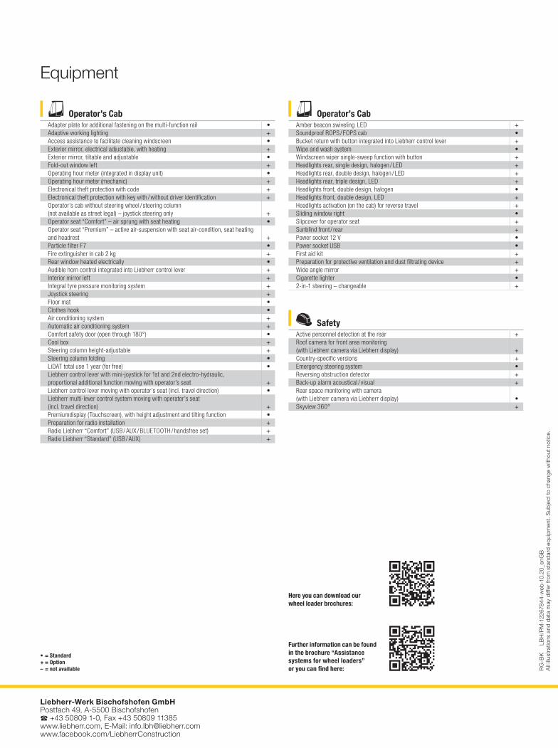
SafetyActive personnel detection at the rear +Roof camera for front area monitoring (with Liebherr camera via Liebherr display) +Country-specific versions +Emergency steering system •Reversing obstruction detector +Back-up alarm acoustical / visual +Rear space monitoring with camera (with Liebherr camera via Liebherr display) •Skyview 360° +
Operator’s CabAdapter plate for additional fastening on the multi-function rail •Adaptive working lighting +Access assistance to facilitate cleaning windscreen •Exterior mirror, electrical adjustable, with heating +Exterior mirror, tiltable and adjustable •Fold-out window left +Operating hour meter (integrated in display unit) •Operating hour meter (mechanic) +Electronical theft protection with code +Electronical theft protection with key with / without driver identification +Operator’s cab without steering wheel / steering column (not available as street legal) – joystick steering only +Operator seat “Comfort” – air sprung with seat heating •Operator seat “Premium” – active air-suspension with seat air-condition, seat heating and headrest +Particle filter F7 •Fire extinguisher in cab 2 kg +Rear window heated electrically •Audible horn control integrated into Liebherr control lever +Interior mirror left +Integral tyre pressure monitoring system +Joystick steering +Floor mat •Clothes hook •Air conditioning system +Automatic air conditioning system +Comfort safety door (open through 180°) •Cool box +Steering column height-adjustable +Steering column folding •LiDAT total use 1 year (for free) •Liebherr control lever with mini-joystick for 1st and 2nd electro-hydraulic, proportional additional function moving with operator’s seat +Liebherr control lever moving with operator’s seat (incl. travel direction) •Liebherr multi-lever control system moving with operator’s seat (incl. travel direction) +Premiumdisplay (Touchscreen), with height adjustment and tilting function •Preparation for radio installation +Radio Liebherr “Comfort” (USB / AUX / BLUETOOTH / handsfree set) +Radio Liebherr “Standard” (USB / AUX) +
Operator’s CabAmber beacon swiveling LED +Soundproof ROPS / FOPS cab •Bucket return with button integrated into Liebherr control lever +Wipe and wash system •Windscreen wiper single-sweep function with button +Headlights rear, single design, halogen / LED +Headlights rear, double design, halogen / LED +Headlights rear, triple design, LED +Headlights front, double design, halogen •Headlights front, double design, LED +Headlights activation (on the cab) for reverse travel +Sliding window right •Slipcover for operator seat +Sunblind front / rear +Power socket 12 V •Power socket USB •First aid kit +Preparation for protective ventilation and dust filtrating device +Wide angle mirror +Cigarette lighter •2-in-1 steering – changeable +
Equipment
• = Standard+ = Option– = not available
Further information can be found in the brochure “Assistance systems for wheel loaders” or you can find here:
Here you can download our wheel loader brochures:
Liebherr-Werk Bischofshofen GmbH Postfach 49, A-5500 Bischofshofen S +43 50809 1-0, Fax +43 50809 11385 www.liebherr.com, E-Mail: [email protected] www.facebook.com/LiebherrConstruction
RG
-BK
LB
H/P
M-1
2267
844-
web
-10.
20_e
nGB
A
ll ill
ustr
atio
ns a
nd d
ata
may
diff
er fr
om s
tand
ard
equi
pmen
t. S
ubje
ct to
cha
nge
with
out n
otic
e.