speckle interferometry of four close binaries - jdso.org part of the seminar, student teams, ... dec...
TRANSCRIPT
Vol. 13 No. 2 April 1, 2017 Page 242 Journal of Double Star Observations
Introduction
Small Telescope Student Research in the San Diego Area
Members of the San Diego astronomical communi-ty are developing a collaborative initiative to introduce high school and college students to science through small telescope astronomical research. As part of this initiative, three community colleges and four high schools are adopting the Astronomical Research Semi-nar supported by the Institute for Student Astronomical Research (InStAR), see http://www.in4star.org.
As part of the seminar, student teams, with assis-tance from the astronomy community, focus on double star research that results in published papers. Expansion of this research to time-series photometry of exoplanet transits, binary star eclipses, brightness variations of intrinsically variable stars, and tumbling asteroids is planned. In addition to time and advice, assistance from the astronomy community extends to providing the fa-cilities (telescopes, etc.) to support student research. One such facility is Tierra Astronomical Institute’s (TAI) 24-inch F/8 Ritchey-Chretien telescope located at
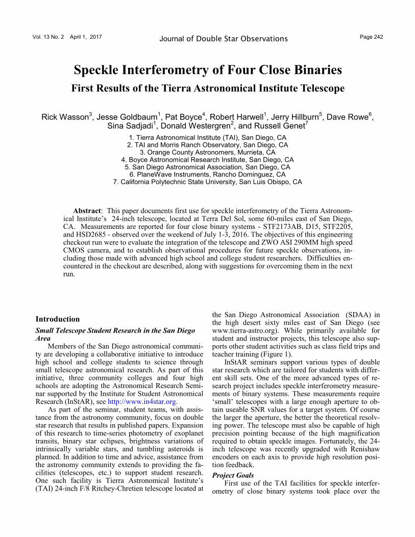
the San Diego Astronomical Association (SDAA) in the high desert sixty miles east of San Diego (see www.tierra-astro.org). While primarily available for student and instructor projects, this telescope also sup-ports other student activities such as class field trips and teacher training (Figure 1).
InStAR seminars support various types of double star research which are tailored for students with differ-ent skill sets. One of the more advanced types of re-search project includes speckle interferometry measure-ments of binary systems. These measurements require ‘small’ telescopes with a large enough aperture to ob-tain useable SNR values for a target system. Of course the larger the aperture, the better the theoretical resolv-ing power. The telescope must also be capable of high precision pointing because of the high magnification required to obtain speckle images. Fortunately, the 24-inch telescope was recently upgraded with Renishaw encoders on each axis to provide high resolution posi-tion feedback.
Project Goals First use of the TAI facilities for speckle interfer-
ometry of close binary systems took place over the
Speckle Interferometry of Four Close Binaries
First Results of the Tierra Astronomical Institute Telescope
Rick Wasson3, Jesse Goldbaum
1, Pat Boyce
4, Robert Harwell
1, Jerry Hillburn
5, Dave Rowe
6,
Sina Sadjadi1, Donald Westergren
2, and Russell Genet
7
1. Tierra Astronomical Institute (TAI), San Diego, CA 2. TAI and Morris Ranch Observatory, San Diego, CA
3. Orange County Astronomers, Murrieta, CA 4. Boyce Astronomical Research Institute, San Diego, CA 5. San Diego Astronomical Association, San Diego, CA
6. PlaneWave Instruments, Rancho Dominguez, CA 7. California Polytechnic State University, San Luis Obispo, CA
Abstract: This paper documents first use for speckle interferometry of the Tierra Astronom-ical Institute’s 24-inch telescope, located at Terra Del Sol, some 60-miles east of San Diego, CA. Measurements are reported for four close binary systems - STF2173AB, D15, STF2205, and HSD2685 - observed over the weekend of July 1-3, 2016. The objectives of this engineering checkout run were to evaluate the integration of the telescope and ZWO ASI 290MM high speed CMOS camera, and to establish observational procedures for future speckle observations, in-cluding those made with advanced high school and college student researchers. Difficulties en-countered in the checkout are described, along with suggestions for overcoming them in the next run.
Vol. 13 No. 2 April 1, 2017 Page 243 Journal of Double Star Observations
Speckle Interferometry of Four Close Binaries ...
weekend of July 1-3, 2016. The project had three pri-mary goals. The first goal was to perform an engineer-ing checkout to see if all the assembled components (hardware, software, and procedures) work together properly. The second goal was to validate the suitability of the 24-inch telescope facility for speckle interferom-etry of binary star systems, and define required or de-sired improvements to hardware, software, or proce-dures. The final goal was to make precise speckle inter-ferometry observations of several binary star systems.
Binary Stars Repeated measurements of the position angles (θ)
and separation (ρ) of the two components of a gravita-tionally bound binary star can lead to the determination of its orbit (Heintz 1978). From Kepler’s first law, we know that the observations must form an ellipse. How-ever, the apparent ellipse we see from Earth could actu-ally be oriented in almost any way in three-dimensional space. To determine this orientation, we use Kepler’s second law of equal areas being swept out in equal in-tervals of time to determine the three-dimensional ori-entation that best fits the observational data.
With an orbit in hand, we know, besides the spatial orientation and the orbital period, the semi-major axes of the orbit as an observed angle in arc seconds (ʺ). If we also know the distance to the binary, often the case from observations made by Tycho (and being greatly refined by Gaia), then we can convert this angular value into an actual physical length of the semi-major axis. We can then apply Kepler’s third law which relates the period, semi-major axis, and combined mass of the two
stars:
where p is the period in years, a is the semi-major axis in astronomical units, and M1 and M2 are the masses of the two stars in solar masses
The dynamical (combined) mass of the two stars can be parsed into individual stellar masses using one of several methods. The most accurate method uses radial velocity curves. Accurate, assumption-free knowledge of individual stellar masses is the founda-tion of stellar evolutionary theory, hence the scientific importance of binary star astrometric measurements.
Obtaining accurate orbital parameters via binary astrometry requires a nearly complete orbit of high quality observations. Binaries with orbital periods less than a century, and ideally less than a decade or so, al-low accurate observations to build up within practical time frames. The problem is that binaries with short periods also have small apparent angular separations, even if they are fairly close to the Earth. These separa-tions are often so small that they are below the seeing limit, and thus the binary appears as a single star (perhaps with a slight elongation).
Speckle Interferometry Anton Labeyrie (1970) realized that very short ex-
posures would freeze out atmospheric fluctuations that were blurring images. Many very short exposures could then be analyzed to determine the position angles and separations of close binary stars, with separations only limited by the resolution of the telescope (about 0.3ʺ for a 24-inch telescope), not atmospheric seeing. The anal-ysis consisted of taking the Fourier transforms of all of the short-exposure images (typically hundreds or thou-sands), averaging these, and then taking the inverse transform to produce an autocorrelogram from which the position angle and separation could be obtained (although there is a 180° ambiguity in the position an-gle).
Recent Hardware and Software Developments Unfortunately, the read noise of CCD cameras op-
erated at high speed is too high for practical speckle interferometry, so images either had to be optically in-tensified, or (more recently) they had to be obtained with an electron-multiplying CCD camera (emCCD) with a gain register just prior to the camera’s analog-to-digital converter. However, emCCD cameras cost be-tween $10,000 and $40,000, are somewhat large and heavy, and have to be used carefully so as not to degrade the gain register with overexposures (Genet 2013).
Figure 1. Tierra Astronomical Institute’s 24-inch F/8 R-C telescope.
32
1 2
ap
M M
Vol. 13 No. 2 April 1, 2017 Page 244 Journal of Double Star Observations
Speckle Interferometry of Four Close Binaries ...
Sony, very recently, developed very low read noise (some less than 1 electron), low cost CMOS chips that have been incorporated into astronomical cameras by firms such as ZWO (Genet et al. 2016 and Ashcraft 2016) and QHY. In addition, Sony just this year re-leased a new line of back-illuminated CMOS detectors with improved near-IR sensitivity. Driven by the mass market for cameras in hand-held electronic devices and many other applications, these low cost CMOS chips offer excellent potential for low-cost speckle imaging.
Equipment A schematic diagram of the TAI speckle interfer-
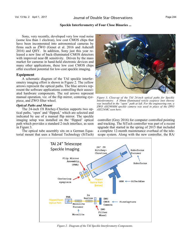
ometry imaging effort is shown in Figure 2. The yellow arrows represent the optical paths. The blue arrows rep-resent the software applications controlling their associ-ated hardware components. The red arrows represent manual operation, viz. of the flip mirror, centering eye-piece, and ZWO filter wheel.
Optical Paths and Mount The 24-inch f/8 Ritchey-Chretien supports two op-
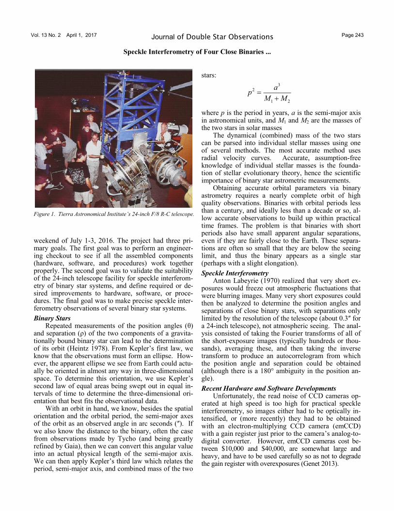
tical paths, ‘open’ and ‘flipped,’ which are selected and indicated by use of a manual flip mirror. The speckle imaging setup was installed on the ‘flipped’ optical path which provides a standard 2-inch interface, as seen in Figure 3.
The optical tube assembly sits on a German Equa-torial mount that uses a Sidereal Technology (SiTech)
controller (Grey 2016) for computer controlled pointing and tracking. The SiTech controller was part of a recent upgrade that started in the spring of 2015 that included a complete 12-month maintenance overhaul of the tele-scope system. Along with the new controller, the RA/
Figure 2. Diagram of the TAI Speckle Interferometry Components.
Figure 3. Close-up of the TAI 24-inch optical paths for Speckle Interferometry. A 30mm illuminated reticle eyepiece (not shown) was installed in the “open” path at left. For the engineering run, a ZWO ASI290MM speckle camera was used in place of the ZWO ASI224MC seen here.
Vol. 13 No. 2 April 1, 2017 Page 245 Journal of Double Star Observations
Speckle Interferometry of Four Close Binaries ...
DEC stepper motors were replaced with brushless DC servo motors and absolute encoder feedback was added to each axis. The brushless servos have shaft encoders on the armature shaft which provide closed loop control of the servos. The Renishaw mount encoders provide additional feedback accuracy (over 67 million ticks/revolution) and very linear motion of the telescope ax-es—virtually eliminating any periodic error using the controller’s Cascade Mode. The SiTech control soft-ware used for this session was SiTechExe version 0.91T.
In the open optical path, a 30mm illuminated reticle eyepiece was used for centering target stars in the field of view. The RoboFocus secondary focuser was used for focusing. After the target star was focused and cen-tered, the flip mirror was manually flipped and the star would appeared in the speckle camera field-of-view.
High magnification is required in speckle interfer-ometry so that details of the speckle pattern can be seen. Simulation studies have shown that Airy disk sampling should optimally be 6 to 8 pixels (Rowe, 2016). Filters are typically used in speckle work to min-imize color dispersion by the atmosphere, which tends to spear out the speckles. Four standard 1¼ inch photo-metric filters, mounted in a ZWO 5-position manual filter wheel, were used for this checkout run: Johnson B and V, and Cousins R and I, filters were located in positions 1 through 4, respectively. Even with filtering, stars beyond about 35-degree zenith angle were not ob-served because no atmospheric dispersion corrector was yet available.
For this first TAI speckle run, it was estimated that a magnification of about 1.75 was needed to magnify
the native f/8 focal ratio to about f/14, yielding a little less than 8 pixels across the Airy Disk. A 2x Barlow was available, providing approximately f/16, for 9 pix-els across the Airy disk, or a plate scale estimated to be 0.06 arc-sec/pixel (but subsequently measured with high precision).
A Moonlite focuser was used for focusing the mag-nified image onto the ZWO high-speed imaging camera (see below). The camera was under the control of Fire-Capture software (Edelmann, 2016). The Moonlite fo-cuser was periodically adjusted to account for changing environmental conditions during the observing session.
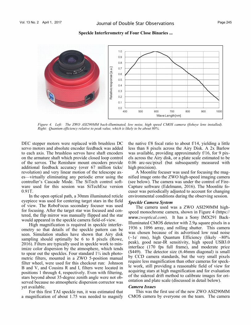
Speckle Camera System The camera used was a ZWO ASI290MM high-
speed monochrome camera, shown in Figure 4 (https://
www.zwoptical.com). It has a Sony IMX291 Back-
Illuminated CMOS detector with 2.9μ square pixels in a 1936 x 1096 array, and rolling shutter. This camera was chosen because of its advertised low read noise (~1e- rms), high Quantum Efficiency (likely ~80% peak), good near-IR sensitivity, high speed USB3.0 interface (170 fps full frame), and moderate price ($449). The detector size (6.46mm diagonal) is small by CCD camera standards, but the very small pixels require less magnification than other cameras for speck-le work, still providing a reasonable field of view for acquiring stars at high magnification and for evaluation of the sidereal drift method to calibrate images for ori-entation and plate scale (discussed in detail below).
Camera Issues This was the first use of the new ZWO ASI290MM
CMOS camera by everyone on the team. The camera
Figure 4. Left: The ZWO ASI290MM back-illuminated, low noise, high speed CMOS camera (fisheye lens installed). Right: Quantum efficiency relative to peak value, which is likely to be about 80%.
Vol. 13 No. 2 April 1, 2017 Page 246 Journal of Double Star Observations
Speckle Interferometry of Four Close Binaries ...
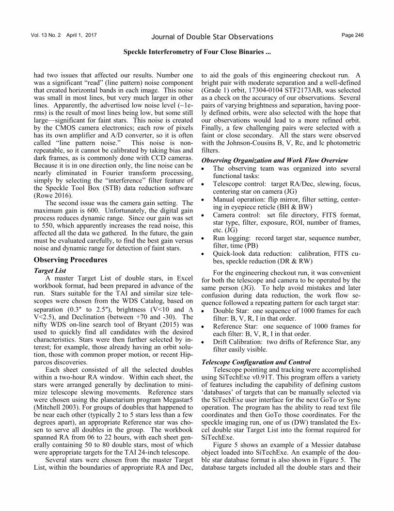
had two issues that affected our results. Number one was a significant “read” (line pattern) noise component that created horizontal bands in each image. This noise was small in most lines, but very much larger in other lines. Apparently, the advertised low noise level (~1e- rms) is the result of most lines being low, but some still large—significant for faint stars. This noise is created by the CMOS camera electronics; each row of pixels has its own amplifier and A/D converter, so it is often called “line pattern noise.” This noise is non-repeatable, so it cannot be calibrated by taking bias and dark frames, as is commonly done with CCD cameras. Because it is in one direction only, the line noise can be nearly eliminated in Fourier transform processing, simply by selecting the “interference” filter feature of the Speckle Tool Box (STB) data reduction software (Rowe 2016).
The second issue was the camera gain setting. The maximum gain is 600. Unfortunately, the digital gain process reduces dynamic range. Since our gain was set to 550, which apparently increases the read noise, this affected all the data we gathered. In the future, the gain must be evaluated carefully, to find the best gain versus noise and dynamic range for detection of faint stars.
Observing Procedures
Target List A master Target List of double stars, in Excel
workbook format, had been prepared in advance of the run. Stars suitable for the TAI and similar size tele-scopes were chosen from the WDS Catalog, based on
separation (0.3ʺ to 2.5ʺ), brightness (V<10 and V<2.5), and Declination (between +70 and -30). The nifty WDS on-line search tool of Bryant (2015) was used to quickly find all candidates with the desired characteristics. Stars were then further selected by in-terest; for example, those already having an orbit solu-tion, those with common proper motion, or recent Hip-parcos discoveries.
Each sheet consisted of all the selected doubles within a two-hour RA window. Within each sheet, the stars were arranged generally by declination to mini-mize telescope slewing movements. Reference stars were chosen using the planetarium program Megastar5 (Mitchell 2003). For groups of doubles that happened to be near each other (typically 2 to 5 stars less than a few degrees apart), an appropriate Reference star was cho-sen to serve all doubles in the group. The workbook spanned RA from 06 to 22 hours, with each sheet gen-erally containing 50 to 80 double stars, most of which were appropriate targets for the TAI 24-inch telescope.
Several stars were chosen from the master Target List, within the boundaries of appropriate RA and Dec,
to aid the goals of this engineering checkout run. A bright pair with moderate separation and a well-defined (Grade 1) orbit, 17304-0104 STF2173AB, was selected as a check on the accuracy of our observations. Several pairs of varying brightness and separation, having poor-ly defined orbits, were also selected with the hope that our observations would lead to a more refined orbit. Finally, a few challenging pairs were selected with a faint or close secondary. All the stars were observed with the Johnson-Cousins B, V, Rc, and Ic photometric filters.
Observing Organization and Work Flow Overview
• The observing team was organized into several functional tasks:
• Telescope control: target RA/Dec, slewing, focus, centering star on camera (JG)
• Manual operation: flip mirror, filter setting, center-ing in eyepiece reticle (BH & BW)
• Camera control: set file directory, FITS format, star type, filter, exposure, ROI, number of frames, etc. (JG)
• Run logging: record target star, sequence number, filter, time (PB)
• Quick-look data reduction: calibration, FITS cu-bes, speckle reduction (DR & RW)
For the engineering checkout run, it was convenient for both the telescope and camera to be operated by the same person (JG). To help avoid mistakes and later confusion during data reduction, the work flow se-quence followed a repeating pattern for each target star: • Double Star: one sequence of 1000 frames for each
filter: B, V, R, I in that order. • Reference Star: one sequence of 1000 frames for
each filter: B, V, R, I in that order. • Drift Calibration: two drifts of Reference Star, any
filter easily visible.
Telescope Configuration and Control Telescope pointing and tracking were accomplished
using SiTechExe v0.91T. This program offers a variety of features including the capability of defining custom ‘databases’ of targets that can be manually selected via the SiTechExe user interface for the next GoTo or Sync operation. The program has the ability to read text file coordinates and then GoTo those coordinates. For the speckle imaging run, one of us (DW) translated the Ex-cel double star Target List into the format required for SiTechExe.
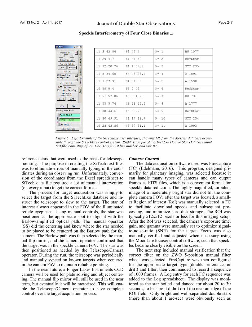
Figure 5 shows an example of a Messier database object loaded into SiTechExe. An example of the dou-ble star database format is also shown in Figure 5. The database targets included all the double stars and their
Vol. 13 No. 2 April 1, 2017 Page 247 Journal of Double Star Observations
Speckle Interferometry of Four Close Binaries ...
reference stars that were used as the basis for telescope pointing. The purpose in creating the SiTech text files was to eliminate errors of manually typing in the coor-dinates during an observing run. Unfortunately, conver-sion of the coordinates from the Excel spreadsheet to SiTech data file required a lot of manual intervention (on every input) to get the correct format.
The process for target acquisition was simply to select the target from the SiTechExe database and in-struct the telescope to slew to the target. The star of interest always appeared in the FOV of the illuminated reticle eyepiece. Using manual controls, the star was positioned at the appropriate spot to align it with the Barlow-amplified optical path. The manual operator (SS) did the centering and knew where the star needed to be placed to be centered on the Barlow path for the camera. The Barlow path was then selected by the man-ual flip mirror, and the camera operator confirmed that the target was in the speckle camera FoV. The star was then positioned as needed by the Telescope/Camera operator. During the run, the telescope was periodically and manually synced on known targets when centered in the camera FoV to maintain reliable pointing.
In the near future, a Finger Lakes Instruments CCD camera will be used for plate solving and object center-ing. The manual flip mirror will still be used in the near term, but eventually it will be motorized. This will ena-ble the Telescope/Camera operator to have complete control over the target acquisition process.
Camera Control The data acquisition software used was FireCapture
(FC) (Edelmann, 2016). This program, designed pri-marily for planetary imaging, was selected because it can handle many types of cameras and can output frames as FITS files, which is a convenient format for speckle data reduction. The highly-magnified, turbulent image of a moderately bright star did not fill the com-plete camera FOV; after the target was located, a small-er Region of Interest (RoI) was manually selected in FC to facilitate download speeds and subsequent pro-cessing, and minimize hard disk storage. The ROI was typically 512x512 pixels or less for this imaging setup. After the RoI was selected, the camera’s exposure time, gain, and gamma were manually set to optimize signal-to-noise-ratio (SNR) for the target. Focus was also manually verified and adjusted when necessary using the MoonLite focuser control software, such that speck-les became clearly visible on the screen.
The next step included manual verification that the correct filter on the ZWO 5-position manual filter wheel was selected. FireCapture was then configured for the appropriate target type (double, reference, or drift) and filter, then commanded to record a sequence of 1000 frames. A Log entry for each FC sequence was added to the Log spreadsheet. The display was moni-tored as the star boiled and danced for about 20 to 30 seconds, to be sure it didn’t drift too near an edge of the ROI field. Only bright and well-separated double stars (more than about 1 arc-sec) were obviously seen as
11 3 43.84 61 45 4 N= 1 BU 1077
11 29 4.7 61 46 40 N= 2 RefStar
11 32 20.76 61 4 57.9 N= 3 STT 235
11 5 34.65 54 48 28.7 N= 4 A 1591
11 3 27.91 54 31 33 N= 5 A 1590
10 59 0.4 55 0 42 N= 6 RefStar
11 51 57.86 48 5 19.5 N= 7 HU 731
11 55 5.74 46 28 36.6 N= 8 A 1777
11 38 44.6 45 6 27 N= 9 RefStar
11 30 49.91 41 17 12.7 N= 10 STT 234
10 28 43.86 45 57 51.1 N= 11 A 1993
Figure 5. Left: Example of the SiTechExe user interface, showing M6 from the Messier database acces-sible through the SiTechExe control system. Right: Example of a SiTechExe Double Star Database input text file, consisting of RA, Dec, Target List line number, and star ID.
Vol. 13 No. 2 April 1, 2017 Page 248 Journal of Double Star Observations
Speckle Interferometry of Four Close Binaries ...
double; a tight and/or faint companion was invisible in the seeing mess, but it was still there!
The targets alternated between double and refer-ence, where the reference is a nearby single star used for “deconvolution” analysis in data reduction. All the same optical imperfections that affect the double star are captured in the reference star images as well, in-cluding even focus and some atmospheric effects. By Fourier Transform deconvolution, these small effects are cancelled from the double star data, greatly improv-ing and sharpening the Autocorrelation end product.
Run Log The Run Log was a simplified version of the Target
List, containing only the observed stars. Data for the Double and Reference stars were first copied from the Target List. As the session progressed, the Log was edited in real time by the dedicated Log Master (PB) while the images were being recorded. For each se-quence of 1000 frames, the star type, FC sequence number, filter, date, and time were added to the Log. After the Reference star observations were completed, two Calibration Drifts, also using the Reference star, were performed and entered into the Log.
Data Reduction
Workflow Data Reduction utilized two programs which are
freely available on-line to amateur astronomers and students, by request to the authors: REDUC (Losse 2015) and Speckle Tool Box (STB) (Rowe 2016). Ex-cel spreadsheet software was also used. The workflow followed this general outline: • Drift Calibration
Inspect images and delete images with no sidereal motion star (REDUC)
STB drift calibration analysis (STB) Summarize and plot results in spreadsheet
(Excel) • Creation of FITS cubes for STB processing (STB) • Processing FITS cubes (STB)
STB Fast Fourier analysis of each frame Average all transforms Write average Power Spectral Density
(PSD) file • Speckle Reduction (STB)
Select input double star and single star ref-erence cubes
Select appropriate dimensional and wave-length filters
Enter camera angle and pixel scale calibra-tion values
Select Output File directory and name
Measure autocorrelogram Save results
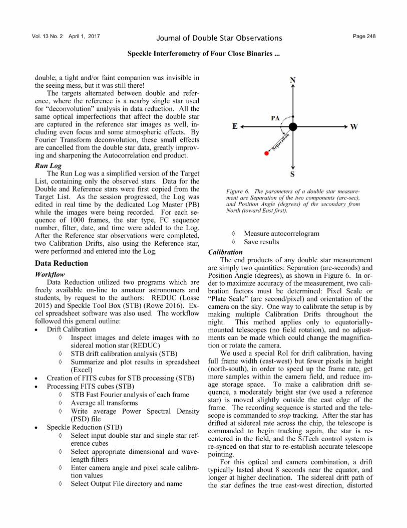
Calibration The end products of any double star measurement
are simply two quantities: Separation (arc-seconds) and Position Angle (degrees), as shown in Figure 6. In or-der to maximize accuracy of the measurement, two cali-bration factors must be determined: Pixel Scale or “Plate Scale” (arc second/pixel) and orientation of the camera on the sky. One way to calibrate the setup is by making multiple Calibration Drifts throughout the night. This method applies only to equatorially-mounted telescopes (no field rotation), and no adjust-ments can be made which could change the magnifica-tion or rotate the camera.
We used a special RoI for drift calibration, having full frame width (east-west) but fewer pixels in height (north-south), in order to speed up the frame rate, get more samples within the camera field, and reduce im-age storage space. To make a calibration drift se-quence, a moderately bright star (we used a reference star) is moved slightly outside the east edge of the frame. The recording sequence is started and the tele-scope is commanded to stop tracking. After the star has drifted at sidereal rate across the chip, the telescope is commanded to begin tracking again, the star is re-centered in the field, and the SiTech control system is re-synced on that star to re-establish accurate telescope pointing.
For this optical and camera combination, a drift typically lasted about 8 seconds near the equator, and longer at higher declination. The sidereal drift path of the star defines the true east-west direction, distorted
Figure 6. The parameters of a double star measure-ment are Separation of the two components (arc-sec), and Position Angle (degrees) of the secondary from North (toward East first).
Vol. 13 No. 2 April 1, 2017 Page 249 Journal of Double Star Observations
Speckle Interferometry of Four Close Binaries ...
slightly by the star bouncing around in the seeing disk. The short exposures, typically the same as the speckle exposures, stop the sidereal motion in each frame, as well as the seeing motion. The least squares slope of the star positions (assumed to be a straight line over the small FOV) calibrates the rotation angle of the camera relative to the true east-west direction. Each frame has a time tag, written by FC into the FITS header; thus the drift sequence records several hundred star positions (star image centroid in pixels) at known times. The sidereal drift rate across the camera field is a function only of the star’s declination; spacing of the star pixel positions versus time is used to calculate the pixel scale calibration constant (arc-seconds / pixel).
The drift calibration data reduction process has been implemented in the STB freeware speckle data reduction program, making data reduction fast and easy. The only preparation needed is to edit the calibra-tion sequence to include only valid frames. Although STB can eliminate out-lying points, a number of non-valid frames, where the star has not yet entered, or has already left, or is not moving at the sidereal rate, would add needlessly spurious data points that should not be included in the calibration. The REDUC program was used to inspect each drift sequence; unwanted frames which didn’t show the star clearly within the frame and moving at the sidereal rate were edited out simply by deleting them. REDUC can calculate the drift angle, and this was used for comparison with STB results.
For calculation of pixel scale, STB reads the time of each frame from the standard FITS header format, written there by FireCapture to the nearest millisecond. The computer clock time does not have to be accurate, but it is assumed to be self-consistent during the short duration of the drift, so that the frames are properly lo-cated in time relative to each other.
The STB calibration procedure is very simple for the user: just enter the declination of the star (hh_mm_ss) and select the folder having the (edited) calibration sequence of FITS frames; they do not have to be in FITS cube format. When the first file is select-ed, STB immediately begins its analysis, centroiding the brightest (usually only) star in each frame and plot-ting its pixel coordinates as a new point on a rapidly-growing X-Y plot.
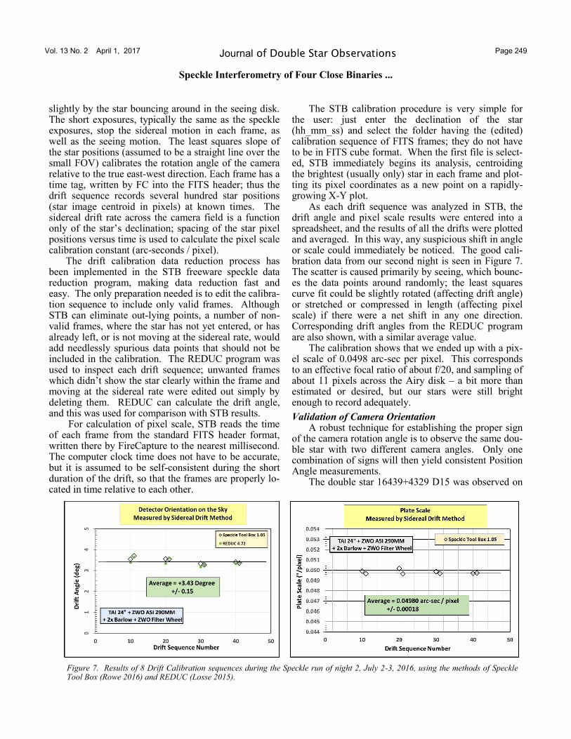
As each drift sequence was analyzed in STB, the drift angle and pixel scale results were entered into a spreadsheet, and the results of all the drifts were plotted and averaged. In this way, any suspicious shift in angle or scale could immediately be noticed. The good cali-bration data from our second night is seen in Figure 7. The scatter is caused primarily by seeing, which bounc-es the data points around randomly; the least squares curve fit could be slightly rotated (affecting drift angle) or stretched or compressed in length (affecting pixel scale) if there were a net shift in any one direction. Corresponding drift angles from the REDUC program are also shown, with a similar average value.
The calibration shows that we ended up with a pix-el scale of 0.0498 arc-sec per pixel. This corresponds to an effective focal ratio of about f/20, and sampling of about 11 pixels across the Airy disk – a bit more than estimated or desired, but our stars were still bright enough to record adequately.
Validation of Camera Orientation A robust technique for establishing the proper sign
of the camera rotation angle is to observe the same dou-ble star with two different camera angles. Only one combination of signs will then yield consistent Position Angle measurements.
The double star 16439+4329 D15 was observed on
Figure 7. Results of 8 Drift Calibration sequences during the Speckle run of night 2, July 2-3, 2016, using the methods of Speckle Tool Box (Rowe 2016) and REDUC (Losse 2015).
Vol. 13 No. 2 April 1, 2017 Page 250 Journal of Double Star Observations
Speckle Interferometry of Four Close Binaries ...
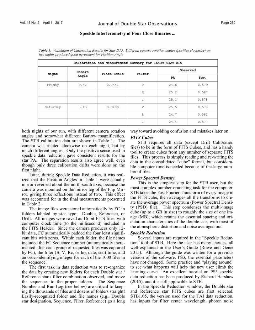
both nights of our run, with different camera rotation angles and somewhat different Barlow magnification. The STB calibration data are shown in Table 1. The camera was rotated clockwise on each night, but by much different angles. Only the positive sense used in speckle data reduction gave consistent results for the star PA. The separation results also agree well, even though only three calibration drifts were done on the first night.
Later, during Speckle Data Reduction, it was real-ized that the Position Angles in Table 1 were actually mirror-reversed about the north-south axis, because the camera was mounted on the mirror leg of the Flip Mir-ror, giving three reflections instead of two. This effect was accounted for in the final measurements presented in Table 2.
The image files were stored automatically by FC in folders labeled by star type: Double, Reference, or Drift. All images were saved as 16-bit FITS files, with computer clock time (to the millisecond) included in the FITS Header. Since the camera produces only 12-bit data, FC automatically padded the four least signifi-cant bits with zeros. Within each folder, the file names included the FC Sequence number (automatically incre-mented after each group of requested files was captured by FC), the filter (B, V, Rc, or Ic), date, start time, and an order-identifying integer for each of the 1000 files in the sequence.
The first task in data reduction was to re-organize the data by creating new folders for each Double star / Reference star / filter combination observed, and move the sequences to the proper folders. The Sequence Number and Run Log (see below) are critical to keep-ing the thousands of files and dozens of folders straight! Easily-recognized folder and file names (e.g., Double star designation, Sequence, Filter, Reference) go a long
way toward avoiding confusion and mistakes later on.
FITS Cubes STB requires all data (except Drift Calibration
files) to be in the form of FITS Cubes, and has a handy tool to create cubes from any number of separate FITS files. This process is simply reading and re-writing the data in the consolidated “cube” format, but considera-ble computer time is needed because of the large num-ber of files.
Power Spectral Density This is the simplest step for the STB user, but the
most complex number-crunching task for the computer. STB takes the Fast Fourier Transform of every image in the FITS cube, then averages all the transforms to cre-ate the average power spectrum (Power Spectral Densi-ty (PSD) file). This step condenses the multi-image cube (up to a GB in size) to roughly the size of one im-age (MB), which retains the essential spacing and ori-entation characteristics of the double star, with most of the atmospheric distortion and noise averaged out.
Speckle Reduction Several inputs are required in the “Speckle Reduc-
tion” tool of STB. Here the user has many choices, all well-explained in the User’s Guide (Rowe and Genet 2015). Although the guide was written for a previous version of the software, PS3, the essential parameters have not changed. Some practice and “playing around” to see what happens will help the new user climb the learning curve. An excellent tutorial on PS3 speckle data reduction has been produced by Richard Harshaw (2015), and it is still applicable to STB.
In the Speckle Reduction window, the Double star and Reference star FITS cubes are first selected. STB1.05, the version used for the TAI data reduction, has inputs for filter center wavelength, photon noise
Calibration and Measurement Summary for 16439+4329 D15
Night Camera
Angle Plate Scale
Observed
Filter
PA Sep.
Friday 9.42 0.0441 V 24.6 0.579
R 25.2 0.587
I 25.3 0.578
Saturday 3.43 0.0498 V 25.5 0.578
R 24.7 0.583
I 24.4 0.577
Table 1. Validation of Calibration Results for Star D15. Different camera rotation angles (positive clockwise) on two nights produced good agreement for Position Angle
Vol. 13 No. 2 April 1, 2017 Page 251 Journal of Double Star Observations
Speckle Interferometry of Four Close Binaries ...
filtering, and interference (line pattern) noise filtering, which are simple and intuitive. Likewise, the calibra-tion inputs are obvious. Inputs for High-Pass and Low-Pass dimensional filters must be calculated, and are explained in detail in the User’s Guide (Rowe and Genet 2015). As soon as the inputs are selected, the Autocorrelogram appears, and a box allows toggling between the power spectrum and autocorrelogram dis-plays. Other buttons display control size and bright-ness.
To make double star measurements of position an-gle and separation, the Astrometry button is selected, and a new window opens with three more inputs, in-cluding the calibration angle and pixel scale again. The third input controls the size of the measuring circle which has appeared on the autocorrelogram display, with an “x” inside that marks the centroid. When the circle is placed over one of the secondary peaks, the measured position angle and separation values appear in the “Observed” boxes. The circle should be sized to contain all of the secondary peak, but none of the pri-mary (central) peak or diffraction rings. When the cir-cle can be moved slightly without the x moving at all,
the circle is sized correctly, the centroid is well defined, and the measurement is “solid.” A right-click opens another window, where the “Set Target Loca-tion” (bottom option) is selected to freeze the measure-ment.
Results Output A browse button makes it easy to designate the out-
put file directory and name. A comment may be added, and “Save Results” writes the measurement data to the output file, which is a spreadsheet in .csv format. For each new double star, a new line is added to the output file. When all the doubles have been measured, it may be convenient to open the .csv file and save it also as an Excel workbook sheet, which gives more formatting flexibility, such as column width or sorting.
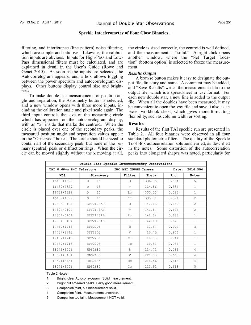
Results Results of the first TAI speckle run are presented in
Table 2. All four binaries were observed in all four standard photometric filters. The quality of the Speckle Tool Box autocorrelation solutions varied, as described in the notes. Some distortion of the autocorrelation peaks into elongated shapes was noted, particularly for
Double Star Speckle Interferometry Observations
TAI 0.60-m R-C Telescope ZWO ASI 290MM Camera Date: 2016.504
WDS Discovery Filter Theta Rho Notes
16439+4329 D 15 B 336.35 0.564 5
16439+4329 D 15 V 334.86 0.584 1
16439+4329 D 15 Rc 335.33 0.583 1
16439+4329 D 15 Ic 335.71 0.591 2
17304-0104 STF2173AB B 142.03 0.669 2
17304-0104 STF2173AB V 141.87 0.624 2
17304-0104 STF2173AB Rc 142.04 0.683 1
17304-0104 STF2173AB Ic 142.89 0.678 1
17457+1743 STF2205 B 11.67 0.972 3
17457+1743 STF2205 V 10.75 0.946 1
17457+1743 STF2205 Rc 10.78 0.941 1
17457+1743 STF2205 Ic 10.51 0.936 1
18571+3451 HDS2685 B 214.72 0.586 4
18571+3451 HDS2685 V 221.33 0.665 4
18571+3451 HDS2685 Rc 218.46 0.616 4
18571+3451 HDS2685 Ic 223.92 0.618 5
Table 2 Notes
1. Bright, clear Autocorrelogram. Solid measurement.
2. Bright but smeared peaks. Fairly good measurement.
3. Companion faint, but measurement solid.
4. Companion faint. Measurement uncertain.
5. Companion too faint. Measurement NOT valid.
Vol. 13 No. 2 April 1, 2017 Page 252 Journal of Double Star Observations
Speckle Interferometry of Four Close Binaries ...
STF 2173AB in the B and V bands, presumably caused by atmospheric dispersion due to its southerly declina-tion (-1 degree).
D 15 The WDS gives magnitudes 9.04 and 9.27, spectral
type K5 for D 15. The latest orbit solution (Alzner 2007) has a period of 120 years and distance of about 88 light years. The orbit is classed as Grade 2 (good) because of complete coverage by micrometer observa-tions.
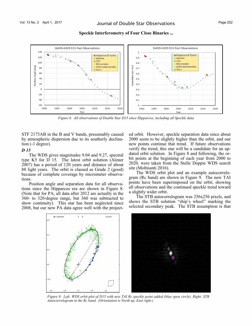
Position angle and separation data for all observa-tions since the Hipparcos era are shown in Figure 8. (Note that for PA, all data after 2012 are actually in the 360- to 320-degree range, but 360 was subtracted to show continuity). This star has been neglected since 2008, but our new PA data agree well with the project-
ed orbit. However, speckle separation data since about 2000 seem to be slightly higher than the orbit, and our new points continue that trend. If future observations verify the trend, this star will be a candidate for an up-dated orbit solution. In Figure 8 and following, the or-bit points at the beginning of each year from 2000 to 2020, were taken from the Stelle Doppie WDS search site (Moltisanti 2016).
The WDS orbit plot and an example autocorrelo-gram (Rc band) are shown in Figure 9. The new TAI points have been superimposed on the orbit, showing all observations and the continued speckle trend toward a slightly wider orbit.
The STB autocorrelogram was 256x256 pixels, and shows the STB solution “ship’s wheel” marking the selected secondary peak. The STB assumption is that
Figure 8. All observations of Double Star D15 since Hipparcos, including all Speckle data.
Figure 9. Left: WDS orbit plot of D15 with new TAI Rc speckle point added (blue open circle). Right: STB Autocorrelogram in the Rc band. (Orientation is North up, East right.)
Vol. 13 No. 2 April 1, 2017 Page 253 Journal of Double Star Observations
Speckle Interferometry of Four Close Binaries ...
the ob-
served orientation is the same as in the WDS orbit plots. When that is not true, care must be taken to se-lect the peak which gives the proper PA quadrant, or as in our case, the mirror image quadrant.
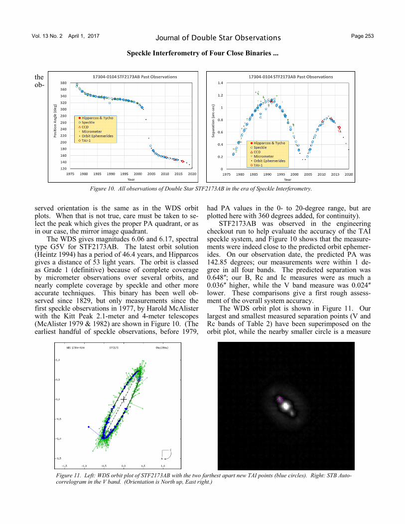
The WDS gives magnitudes 6.06 and 6.17, spectral type G5V for STF2173AB. The latest orbit solution (Heintz 1994) has a period of 46.4 years, and Hipparcos gives a distance of 53 light years. The orbit is classed as Grade 1 (definitive) because of complete coverage by micrometer observations over several orbits, and nearly complete coverage by speckle and other more accurate techniques. This binary has been well ob-served since 1829, but only measurements since the first speckle observations in 1977, by Harold McAlister with the Kitt Peak 2.1-meter and 4-meter telescopes (McAlister 1979 & 1982) are shown in Figure 10. (The earliest handful of speckle observations, before 1979,
had PA values in the 0- to 20-degree range, but are plotted here with 360 degrees added, for continuity).
STF2173AB was observed in the engineering checkout run to help evaluate the accuracy of the TAI speckle system, and Figure 10 shows that the measure-ments were indeed close to the predicted orbit ephemer-ides. On our observation date, the predicted PA was 142.85 degrees; our measurements were within 1 de-gree in all four bands. The predicted separation was 0.648ʺ; our B, Rc and Ic measures were as much a 0.036ʺ higher, while the V band measure was 0.024ʺ lower. These comparisons give a first rough assess-ment of the overall system accuracy.
The WDS orbit plot is shown in Figure 11. Our largest and smallest measured separation points (V and Rc bands of Table 2) have been superimposed on the orbit plot, while the nearby smaller circle is a measure
Figure 10. All observations of Double Star STF2173AB in the era of Speckle Interferometry.
Figure 11. Left: WDS orbit plot of STF2173AB with the two farthest apart new TAI points (blue circles). Right: STB Auto-correlogram in the V band. (Orientation is North up, East right.)
Vol. 13 No. 2 April 1, 2017 Page 254 Journal of Double Star Observations
Speckle Interferometry of Four Close Binaries ...
made in 1970 by a visual interferometry technique on the previous orbit (Laques et al. 1971). Both new points fall very near the orbit. The STB autocorrelogram, also seen in Figure 11, was 256 x 256 pixels, and shows the STB solution “ship’s wheel” marking the selected sec-ondary peak. The slight smearing of the peaks into an oval shape, as noted in Table 2, was likely caused by atmospheric dispersion; it was greatest in the B and V bands, but not noticeable in Rc and Ic. Although the star was observed not far from the meridian, its declina-tion is about -1 degree, so it was at least 34 degrees from the zenith at our latitude, and atmospheric disper-sion is strongest at shorter wavelengths.
STF 2205 The WDS gives magnitudes 9.37 and 9.59, spectral
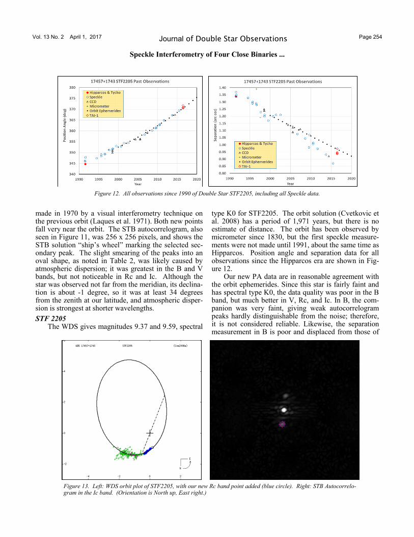
type K0 for STF2205. The orbit solution (Cvetkovic et al. 2008) has a period of 1,971 years, but there is no estimate of distance. The orbit has been observed by micrometer since 1830, but the first speckle measure-ments were not made until 1991, about the same time as Hipparcos. Position angle and separation data for all observations since the Hipparcos era are shown in Fig-ure 12.
Our new PA data are in reasonable agreement with the orbit ephemerides. Since this star is fairly faint and has spectral type K0, the data quality was poor in the B band, but much better in V, Rc, and Ic. In B, the com-panion was very faint, giving weak autocorrelogram peaks hardly distinguishable from the noise; therefore, it is not considered reliable. Likewise, the separation measurement in B is poor and displaced from those of
Figure 12. All observations since 1990 of Double Star STF2205, including all Speckle data.
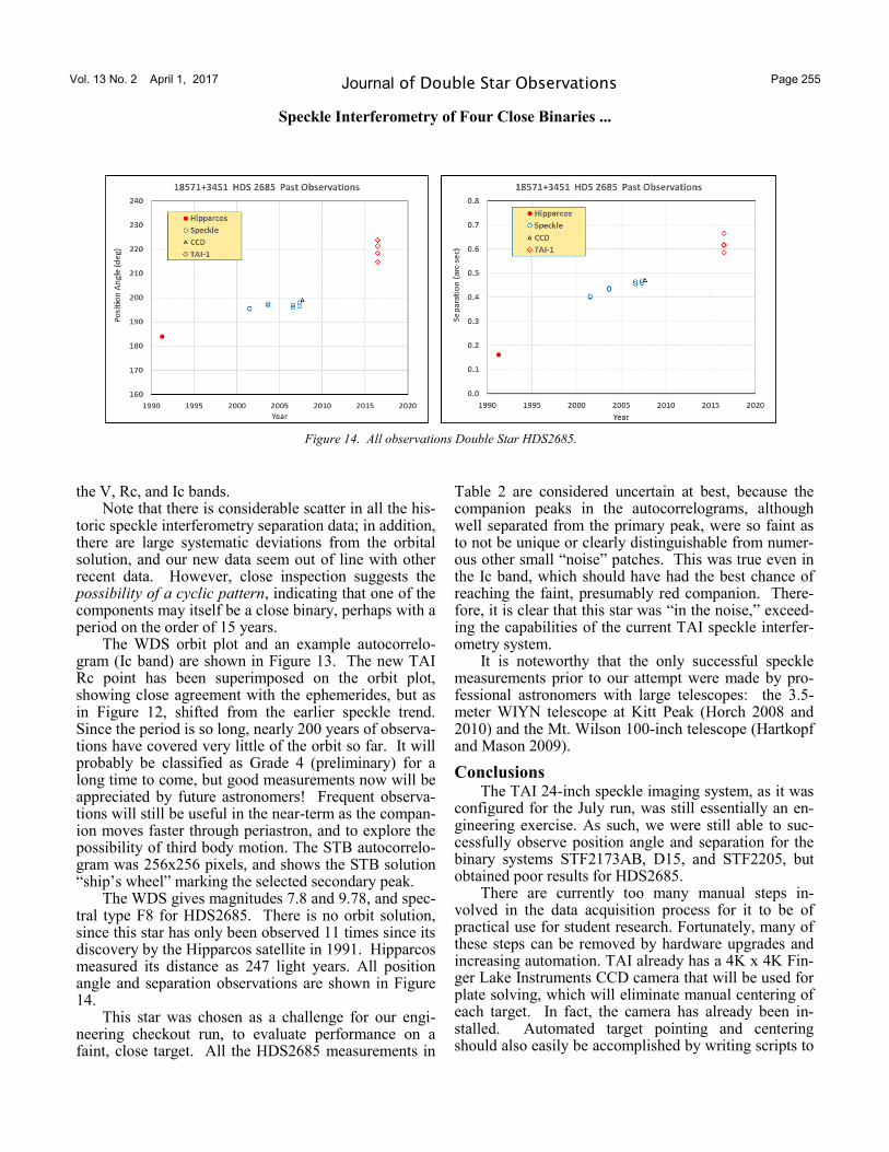
Figure 13. Left: WDS orbit plot of STF2205, with our new Rc band point added (blue circle). Right: STB Autocorrelo-gram in the Ic band. (Orientation is North up, East right.)
Vol. 13 No. 2 April 1, 2017 Page 255 Journal of Double Star Observations
Speckle Interferometry of Four Close Binaries ...
the V, Rc, and Ic bands. Note that there is considerable scatter in all the his-
toric speckle interferometry separation data; in addition, there are large systematic deviations from the orbital solution, and our new data seem out of line with other recent data. However, close inspection suggests the possibility of a cyclic pattern, indicating that one of the components may itself be a close binary, perhaps with a period on the order of 15 years.
The WDS orbit plot and an example autocorrelo-gram (Ic band) are shown in Figure 13. The new TAI Rc point has been superimposed on the orbit plot, showing close agreement with the ephemerides, but as in Figure 12, shifted from the earlier speckle trend. Since the period is so long, nearly 200 years of observa-tions have covered very little of the orbit so far. It will probably be classified as Grade 4 (preliminary) for a long time to come, but good measurements now will be appreciated by future astronomers! Frequent observa-tions will still be useful in the near-term as the compan-ion moves faster through periastron, and to explore the possibility of third body motion. The STB autocorrelo-gram was 256x256 pixels, and shows the STB solution “ship’s wheel” marking the selected secondary peak.
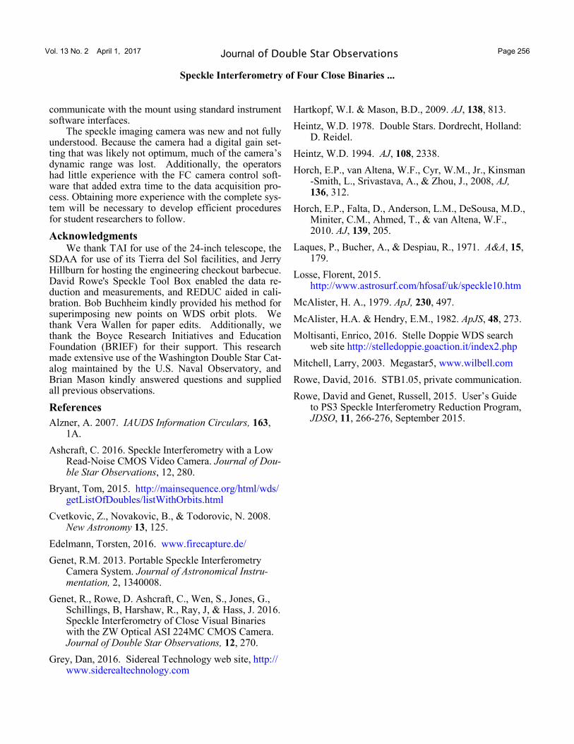
The WDS gives magnitudes 7.8 and 9.78, and spec-tral type F8 for HDS2685. There is no orbit solution, since this star has only been observed 11 times since its discovery by the Hipparcos satellite in 1991. Hipparcos measured its distance as 247 light years. All position angle and separation observations are shown in Figure 14.
This star was chosen as a challenge for our engi-neering checkout run, to evaluate performance on a faint, close target. All the HDS2685 measurements in
Table 2 are considered uncertain at best, because the companion peaks in the autocorrelograms, although well separated from the primary peak, were so faint as to not be unique or clearly distinguishable from numer-ous other small “noise” patches. This was true even in the Ic band, which should have had the best chance of reaching the faint, presumably red companion. There-fore, it is clear that this star was “in the noise,” exceed-ing the capabilities of the current TAI speckle interfer-ometry system.
It is noteworthy that the only successful speckle measurements prior to our attempt were made by pro-fessional astronomers with large telescopes: the 3.5-meter WIYN telescope at Kitt Peak (Horch 2008 and 2010) and the Mt. Wilson 100-inch telescope (Hartkopf and Mason 2009).
Conclusions The TAI 24-inch speckle imaging system, as it was
configured for the July run, was still essentially an en-gineering exercise. As such, we were still able to suc-cessfully observe position angle and separation for the binary systems STF2173AB, D15, and STF2205, but obtained poor results for HDS2685.
There are currently too many manual steps in-volved in the data acquisition process for it to be of practical use for student research. Fortunately, many of these steps can be removed by hardware upgrades and increasing automation. TAI already has a 4K x 4K Fin-ger Lake Instruments CCD camera that will be used for plate solving, which will eliminate manual centering of each target. In fact, the camera has already been in-stalled. Automated target pointing and centering should also easily be accomplished by writing scripts to
Figure 14. All observations Double Star HDS2685.
Vol. 13 No. 2 April 1, 2017 Page 256 Journal of Double Star Observations
Speckle Interferometry of Four Close Binaries ...
communicate with the mount using standard instrument software interfaces.
The speckle imaging camera was new and not fully understood. Because the camera had a digital gain set-ting that was likely not optimum, much of the camera’s dynamic range was lost. Additionally, the operators had little experience with the FC camera control soft-ware that added extra time to the data acquisition pro-cess. Obtaining more experience with the complete sys-tem will be necessary to develop efficient procedures for student researchers to follow.
Acknowledgments We thank TAI for use of the 24-inch telescope, the
SDAA for use of its Tierra del Sol facilities, and Jerry Hillburn for hosting the engineering checkout barbecue. David Rowe's Speckle Tool Box enabled the data re-duction and measurements, and REDUC aided in cali-bration. Bob Buchheim kindly provided his method for superimposing new points on WDS orbit plots. We thank Vera Wallen for paper edits. Additionally, we thank the Boyce Research Initiatives and Education Foundation (BRIEF) for their support. This research made extensive use of the Washington Double Star Cat-alog maintained by the U.S. Naval Observatory, and Brian Mason kindly answered questions and supplied all previous observations.
References
Alzner, A. 2007. IAUDS Information Circulars, 163, 1A.
Ashcraft, C. 2016. Speckle Interferometry with a Low Read-Noise CMOS Video Camera. Journal of Dou-ble Star Observations, 12, 280.
Bryant, Tom, 2015. http://mainsequence.org/html/wds/getListOfDoubles/listWithOrbits.html
Cvetkovic, Z., Novakovic, B., & Todorovic, N. 2008. New Astronomy 13, 125.
Edelmann, Torsten, 2016. www.firecapture.de/
Genet, R.M. 2013. Portable Speckle Interferometry Camera System. Journal of Astronomical Instru-mentation, 2, 1340008.
Genet, R., Rowe, D. Ashcraft, C., Wen, S., Jones, G., Schillings, B, Harshaw, R., Ray, J, & Hass, J. 2016. Speckle Interferometry of Close Visual Binaries with the ZW Optical ASI 224MC CMOS Camera. Journal of Double Star Observations, 12, 270.
Grey, Dan, 2016. Sidereal Technology web site, http://www.siderealtechnology.com
Hartkopf, W.I. & Mason, B.D., 2009. AJ, 138, 813.
Heintz, W.D. 1978. Double Stars. Dordrecht, Holland: D. Reidel.
Heintz, W.D. 1994. AJ, 108, 2338.
Horch, E.P., van Altena, W.F., Cyr, W.M., Jr., Kinsman-Smith, L., Srivastava, A., & Zhou, J., 2008, AJ, 136, 312.
Horch, E.P., Falta, D., Anderson, L.M., DeSousa, M.D., Miniter, C.M., Ahmed, T., & van Altena, W.F., 2010. AJ, 139, 205.
Laques, P., Bucher, A., & Despiau, R., 1971. A&A, 15, 179.
Losse, Florent, 2015. http://www.astrosurf.com/hfosaf/uk/speckle10.htm
McAlister, H. A., 1979. ApJ, 230, 497.
McAlister, H.A. & Hendry, E.M., 1982. ApJS, 48, 273.
Moltisanti, Enrico, 2016. Stelle Doppie WDS search web site http://stelledoppie.goaction.it/index2.php
Mitchell, Larry, 2003. Megastar5, www.wilbell.com
Rowe, David, 2016. STB1.05, private communication.
Rowe, David and Genet, Russell, 2015. User’s Guide to PS3 Speckle Interferometry Reduction Program, JDSO, 11, 266-276, September 2015.