specification - mts power products manual.pdf · specification item description dc supply 9.0 to 35...
TRANSCRIPT


Specification
ITEM DESCRIPTION
DC Supply 9.0 to 35 VDC
Alternator Input Range 5 ~ 300VAC
Alternator Input Frequency 50/60 Hz
MPU Signal Input Range ± 2V to 70V Peak
Rated MPU Frequency 100 Hz ~ 10,000 Hz
Operating Temperature -20 °C to +70 °C
Relative Humidity 90% or Below
Power Consumption Under 3VA
Weight 200 gram
Terminals Detail
Pin NO.
Current Max. DESCRIPTION
1 10mA Lamp test input
2 10mA Oil switch input
3 10mA Temperature switch input
4 10A Auxiliary switch input
5 10A Start signal output
6 10A Battery negative input
7 10mA AUTO switch input
8~9 10mA Remote start signal input
10 10mA Test switch input
11 10A Fuel/Stop signal output
12 300mA Pre-heat signal output
13~18 300mA Annunciator signal output
19 300mA Warm-up signal output
20 1A Annunciator common used only Don’t use as main ground connection
21 1A Accessory ON signal output
22 1A IDLE control output
23 10A Battery positive input
TEST Operation To initiate a start sequence moves the external toggle switch to
the on TEST (Manual Start) position.
First , the pre-heat timer begins by energizing terminal 12. If
Pre-Heat is not uses, simple no not use this terminal.
Second , the Engine Fuel Solenoid energizes terminal 11, and
idle terminals 22.
Third , after a 1 sec. delay, the starter motor energizes, and the
engine cranks for the duration of the crank timer.
Fourth , after the engine (start/fires), the starter motor
disengaged and locked out by using the 18-Hertz signal from the
generator or the signal from the MPU. Alternatively, the oil
pressure switch can serve as an additional back up crank
disconnect.
Fifth , after the engine fires and if the Engine Idle option is used,
the ENGINE RUNNING LED will continuous flashing in idle
indicating the status is IDLE. (If engine idle is not used -- set
adjustment, "E" full counterclockwise)
Sixth , if the engine does not start the first time the module will try
again to start the engine 2 more times and stop after the third try.
If the generator fail to start, move the
select switch to the OFF (Reset) position,
Find out why the engine failed to start
before making any more start attempts.
Seven , after the generator starts, the module allows Oil Pressure,
Engine Temperature and engine speed to stabilize without
triggering any faults for 20 seconds.
Moving the toggle switch to the OFF position, Stops the engine
immediately
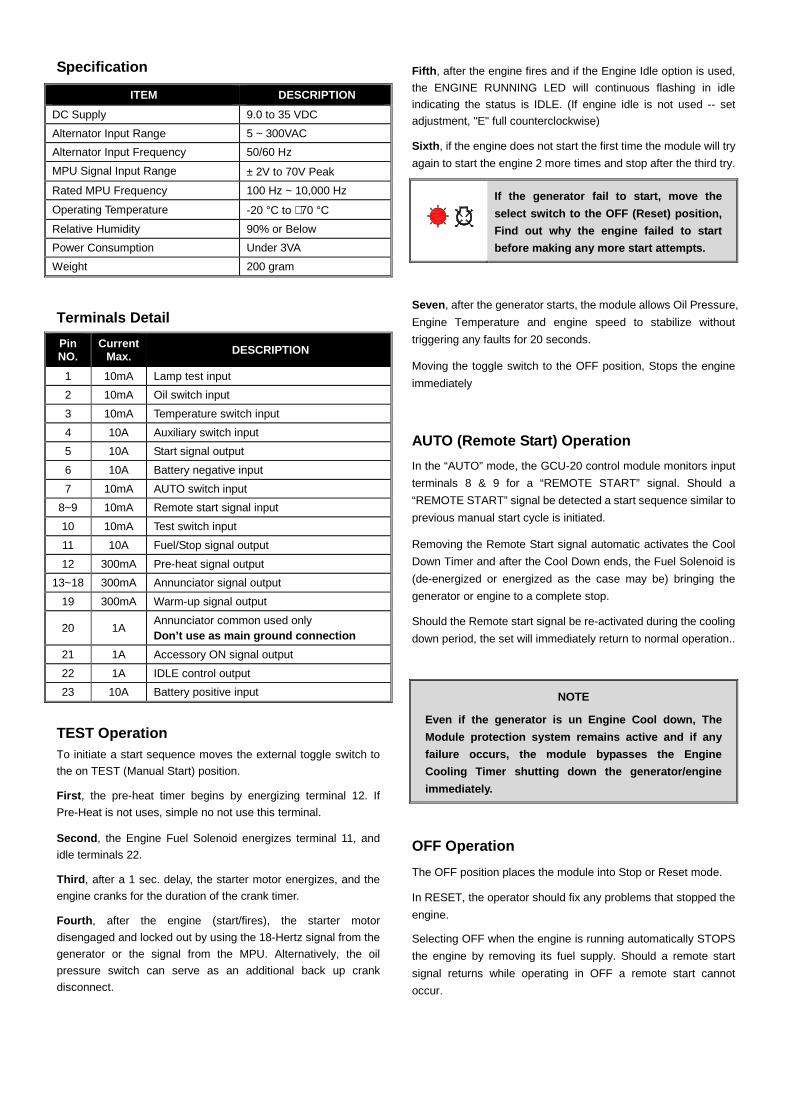
AUTO (Remote Start) Operation
In the “AUTO” mode, the GCU-20 control module monitors input
terminals 8 & 9 for a “REMOTE START” signal. Should a
“REMOTE START” signal be detected a start sequence similar to
previous manual start cycle is initiated.
Removing the Remote Start signal automatic activates the Cool
Down Timer and after the Cool Down ends, the Fuel Solenoid is
(de-energized or energized as the case may be) bringing the
generator or engine to a complete stop.
Should the Remote start signal be re-activated during the cooling
down period, the set will immediately return to normal operation..
NOTE
Even if the generator is un Engine Cool down, The
Module protection system remains active and if any
failure occurs, the module bypasses the Engine
Cooling Timer shutting down the generator/engine
immediately.
OFF Operation
The OFF position places the module into Stop or Reset mode.
In RESET, the operator should fix any problems that stopped the
engine.
Selecting OFF when the engine is running automatically STOPS
the engine by removing its fuel supply. Should a remote start
signal returns while operating in OFF a remote start cannot
occur.
DE
ABC
DE
ABC

17
20
1819
23
RelayStart
3
21
21
4
22
1516
1413
RelayFuel
65 987
G
RS
RF
Start
Batt(
-)
Select Switch
Fuel Auto
Test
OFF
RemoteStart
Battery
10A
Low Oil
High Temp GCU-20
L1
L2
L3
N
L1
L2
L3
N
LOAD
+
Add this wire
AdjustmentsA Engine Pre-Heat Timer Full CCW
B Energized to STOP Timer
C Engine Cool-down Timer (Adj 0 to 300sec)
D Starter Crank time Timer (Adj 1 to 15sec) 1/2 way
E Engine Idle (Governor) Timer
Setting DIP/switchesSW 1 Oil Pressure Switch Used for Crank DisconnectON - Disable OFF – Enable
SW 2 Oil Pressure Switch TypeON - Normal Open OFF – Normally Close
SW 3 Engine Stop SettingON - Energize to Start OFF – Energize to STOP
SW 4 Generator Frequency (Ignore if it is a Water Pump)ON - 50Hz OFF – 60Hz
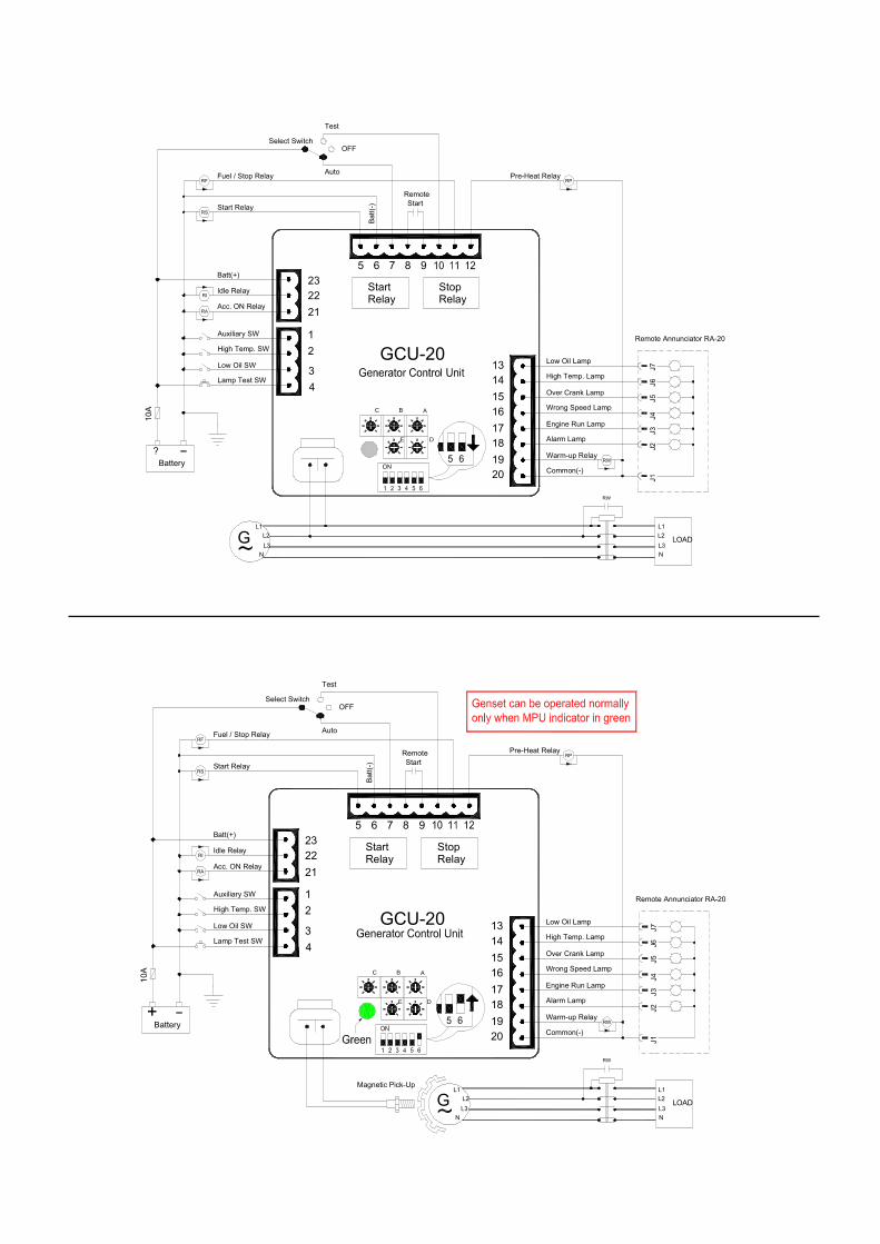
SW 5 MPU SettingON – Enable (used to Program Speed) OFF - Disable
SW 6 Speed Signal TypeON – Use MPU for speed sensingOFF – Use AC generator frequency for speed sensing
Normal Settings
Full CCW
Full CCW
Full CCW
BASIC SET-UP
A
DE
BC
Not over 300 volts
12 or 24v
Energize to STOP