sparta spart a - kronos audiokronosaudio.com/assets/sparta-assembly-instructions-rev2.pdf · the...
TRANSCRIPT

S P A R T A
S P A R T A
S P A R T A
S P A R T A
A S S E M B L Y I N S T R U C T I O N S

THANK YOUfor purchasing the Kronos Sparta turntable.
The Sparta has been designed to produce the best sound reproduction possible from a vinyl record. It is built without compromise for this single purpose. It is a state-of-the-art hand built instrument. Each Sparta is individually constructed, assembled and tested to ensure years of musical enjoyment.
It is important that you take the time to read this manual before assembling, installing and operating your Sparta. Assembly is simple, provided you follow all the necessary steps. Leveling of the turntable is particularly important.
Once this is done, you will find the Sparta will not require frequent adjustments as it is a very stable platform. Of course, mandatory care must be given to setting up the tone arm and cartridge, as in any other turntable. Make sure you use a quality protractor to properly align the cartridge.
Please keep in mind that your Sparta will need to settle for its first few days of operation. The self-learning speed guidance system will calibrate itself with use. After a few hours it will attain speed more quickly with a minimum of fluctuation. The micro-processor controlled speed adjustments are deliberately done in a slow and deliberate manner. This use of minimal power reduces motor induced vibration and hence optimum musical enjoyment.
Enjoy.
Louis DesjardinsDesigner and CEO of Kronos Audio Products inc.

Remove Sparta from crate. Put Sparta on a solid surface. Do not remove the styrofoam spacer blocks at this moment.
Remove the suspension caps by loosening the screws using the 5/32 spanner.
Remove top plate and set aside.
Adjust level of base using the 4 adjustable feet and the level located in the base.
1
2
3
4
1
2
3
4
5
6
Place bearing ball on the top of the shaft.Make sure the ball stays in place. Carefullyinstall the lower platter. make sure the platter spins freely. If it does not, the ballmight have fallen from the top of the shaft.If in doubt, remove platter and start again.
Remove Sparta from the crate. Put Sparta on a solid surface. Do not remove the Styrofoam spacer blocks at this moment.
Remove the suspension caps by loosening the screws using the 5/32 spanner.
Remove top plate and set aside.
Adjust level of base using the 4 adjustablefeet and the level located in the base.
Fill the oil well with 8ml. Kronos Oil.Make sure to put oil on the bearing shaft.Do not use any other type oil. Do not overfill.

Fill the oil well with 8 ml of Kronos oil. Make sure to put oil on the bearing shaft. Do not use any other oil type. Do not overfill.
Place the bearing ball on the top of the shaft. Make sure the ball stays in place.
Install carefully the lower platter. Make sure the platter spins freely. If it does not, the ball might have fallen from the top of the shaft. If in doubt, remove platter and start again.
Install belt using the top groove of the pulley.
5
6
7
8
1
2
3
4
5
6
Place bearing ball on the top of the shaft.Make sure the ball stays in place. Carefullyinstall the lower platter. make sure the platter spins freely. If it does not, the ballmight have fallen from the top of the shaft.If in doubt, remove platter and start again.
Remove Sparta from the crate. Put Sparta on a solid surface. Do not remove the Styrofoam spacer blocks at this moment.
Remove the suspension caps by loosening the screws using the 5/32 spanner.
Remove top plate and set aside.
Adjust level of base using the 4 adjustablefeet and the level located in the base.
Fill the oil well with 8ml. Kronos Oil.Make sure to put oil on the bearing shaft.Do not use any other type oil. Do not overfill.
Repeat steps 6 and 7 to install the top platter
Install belt using the top groove of the pulley.
Connect the control cables on theSparta. There is a 3 pin connector anda 4 pin connector
Connect the control cables to thepower supply, again being careful toconnect the 4 pin and 3 pin connectorsat their rightful location. Connect the strobe cable using the RCA connector.
7
8
9
10
11
12
13
Reinstall the top plate and re-install the suspension caps by tightening the screws using the 5/32 spanner.
Install the arm board. The arm board can slide to adjust the arm alignment.
ONCE THE ARM IS IN PLACE:Remove the Styrofoam spacers. Adjust the top plate level using theadjusters through the center ofthe suspension caps.
Lock the suspension caps by tightening2 set screws betewwn the suspensiono-rings...as shown.

Reinstall the top plate and rinstall the suspension caps by tightening the screws using the 5/32 spanner.
Repeat the steps 6, 7 and 8 to install the top platter.
Install the arm board. The arm board can slide to adjust the arm alignment.
ONCE THE ARM IS IN PLACE: remove the styrofoam spacers. Adjust the top plate level using the adjusters through the center of the suspension caps.
9
10
11
12
Repeat steps 6 and 7 to install the top platter
Install belt using the top groove of the pulley.
Connect the control cables on theSparta. There is a 3 pin connector anda 4 pin connector
Connect the control cables to thepower supply, again being careful toconnect the 4 pin and 3 pin connectorsat their rightful location. Connect the strobe cable using the RCA connector.
7
8
9
10
11
12
13
Reinstall the top plate and re-install the suspension caps by tightening the screws using the 5/32 spanner.
Install the arm board. The arm board can slide to adjust the arm alignment.
ONCE THE ARM IS IN PLACE:Remove the Styrofoam spacers. Adjust the top plate level using theadjusters through the center ofthe suspension caps.
Lock the suspension caps by tightening2 set screws betewwn the suspensiono-rings...as shown.
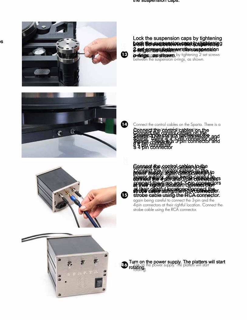
Lock the suspension caps by tightening 2 set screws between the suspension o-rings, as shown.
Connect the control cables on the Sparta. There is a 3-pin connector and a 4-pin connector.
Connect the control cables to the power supply, again being careful to connect the 3-pin and the 4-pin connectors at their rightful location. Connect the strobe cable using the RCA connector.
Turn on the power supply. The platters will start rotating.
13
14
15
16
Repeat steps 6 and 7 to install the top platter
Install belt using the top groove of the pulley.
Connect the control cables on theSparta. There is a 3 pin connector anda 4 pin connector
Connect the control cables to thepower supply, again being careful toconnect the 4 pin and 3 pin connectorsat their rightful location. Connect the strobe cable using the RCA connector.
7
8
9
10
11
12
13
Reinstall the top plate and re-install the suspension caps by tightening the screws using the 5/32 spanner.
Install the arm board. The arm board can slide to adjust the arm alignment.
ONCE THE ARM IS IN PLACE:Remove the Styrofoam spacers. Adjust the top plate level using theadjusters through the center ofthe suspension caps.
Lock the suspension caps by tightening2 set screws betewwn the suspensiono-rings...as shown.
The strobe can be used to adjust the playback speed. To change the speed, the toggle switchmust be depressed toward the + or -. Each click of the toggle will change the speed insmall steps.
Turn on the power supply. The platters will startrotating.
Speed can be selected using the 33/45 toggle switch.
16
14
15
17
ONCE THE SPEED IS SET:Push the memory switch UP AND DOWNto keep the setting in memory. You need todo this for both 33 AND 45.Once set, the system will remain calibrateduntil a new adjustment is made andmemorized.memorized. The speed will remain seteven if the power supply is disconnected.

Speed can be selected using the 33/45 toggle switch.
The strobe ca be used to adjust the playback speed. To change the speed, the adjustment toggle switch must be depressed toward the + or -. Each click of the toggle will change the speed in small steps.
ONCE THE SPEED IS SET: Push the memory switch up and down to keep setting in memory. You need to do this for both 33 and 45. Once set, the system will remain calibrated until a new adjustment is made and memorized. The speed will remain set even if the power supply is disconnected.
17
18
19
The strobe can be used to adjust the playback speed. To change the speed, the toggle switchmust be depressed toward the + or -. Each click of the toggle will change the speed insmall steps.
Turn on the power supply. The platters will startrotating.
Speed can be selected using the 33/45 toggle switch.
16
14
15
17
ONCE THE SPEED IS SET:Push the memory switch UP AND DOWNto keep the setting in memory. You need todo this for both 33 AND 45.Once set, the system will remain calibrateduntil a new adjustment is made andmemorized.memorized. The speed will remain seteven if the power supply is disconnected.
TECHNICAL SPECIFICATIONS:
dimensions: 20 in (W) x 14 in (D) x 11 in (H) 51 cm (W) x 36 cm (D) x 28 cm (H) weight: 70 lbs / 32 kg
crate dimensions: 24 in (W) x 32 in (D) x 16 in (H) 61 cm (W) x 81 cm (D) x 41 cm (H)shipping weight: 95 lbs / 43 kg
rotational speed: 33.3 rpm and 45 rpm
power supply: dual channel pure class A linear DCac voltage input: 110V or 220V factory setdc voltage output: 0 to 5 volt, cpu controlled, factory calibrateddc transmission: pico 3 pin cabletransmission: pico 4 pin cablemotors: 2432 precious metal brushes dc motors (qty 2)motor mounts: delrin capped aluminum tubes
speed guidance system: continuous open loop feedback, user speed adjustable sensors type: optical diode I/O top motor tachymetercorrection cycle: 60 times /rotation. 0.15% max., 0.05% min.strobe: cpu generated 120 Hz with LED output
tonearm lenght: 9 inches to 10.5 inches (229 mm to 267 mm)platters type: composite compressed phenolic/aluminum, balancedplatter weight: 27 lbs (12kg) / platterdrive: 1 silicone/viton 2.3 string belt / platter
main bearings: dual hydraulic isolated inverted sleeve and ballshaft type: grounded heat hardened tool steelball type: precision steellubricant: 8 ml. variable viscosity synthetic oilservice interval: 5 years (clean and re-oil)
suspension: full floating top suspendedelastomers: 317 o-rings , viton/silicone proprietary mix

4035, rue Saint-Ambroise, suite 414, Montreal (Quebec) Canada H4C 2E1
www.kronosaudio.com • [email protected]© 2014 Kronos audio