sp s i s m
TRANSCRIPT

SP SERIES
INSTALLATION AND SETUP MANUAL
Old Number M97001 - ISSUE 1
New Number MSP000H

SERVOSTAR SP SERIES RECORD OF REVISIONS
A
RECORD OF REVISIONS
( INSTALLATION AND SETUP MANUAL M97001 )
ISSUE NO.
(Revision) DATE CHANGED PAGES/BRIEF DESCRIPTION OF CHANGE CHANGE NO.
0
1
6/11/97
1/26/98
Original Release Issue
Incorporate Update Review Comments

RECORD OF REVISIONS SERVOSTAR SP SERIES
B
:

SERVOSTAR SP SERIES TABLE OF CONTENTS
i
TABLE OF CONTENTS
RECORD OF REVISIONS........................................................................................ A
TABLE OF CONTENTS Contents .............................................................................................................................................. i - iii List of Figures ..................................................................................................................................... iv List of Tables ...................................................................................................................................... v List of Drawings.................................................................................................................................. viINTRODUCTION How To Use This Manual................................................................................................................... i-1 Installation and Start-up Guidelines.................................................................................................... i-2 Customer Response............................................................................................................................. i-3 Copyright Information ........................................................................................................................ i-4 European Community (EC) Declaration of Conformity...................................................................... i-5 Abbreviations...................................................................................................................................... i-6
SECTION 1 SYSTEM DESCRIPTION
1.1 Introduction......................................................................................................................................... 1-11.2 Features............................................................................................................................................... 1-11.3 Theory of Operation............................................................................................................................ 1-21.3.1 Power Supply Module...................................................................................................................... 1-21.3.2 SERVOSTAR SP Drive Module ..................................................................................................... 1-21.3.3 Brushless DC Motor ........................................................................................................................ 1-31.3.4 Power Up/Down Sequencing ........................................................................................................... 1-31.4 Typical System Diagram..................................................................................................................... 1-41.5 Signal Information .............................................................................................................................. 1-41.5.1 Current Feedback Signals ................................................................................................................ 1-41.5.2 PWM Input Command Signals ........................................................................................................ 1-41.5.3 Analog Input Signals........................................................................................................................ 1-51.5.4 Six-step Commutation...................................................................................................................... 1-51.6 Current Ratings and Duty Cycles ........................................................................................................ 1-5
SECTION 2 INSTALLATION
2.1 Introduction......................................................................................................................................... 2-12.2 Safety Information .............................................................................................................................. 2-12.3 Conventions ........................................................................................................................................ 2-22.3.1 Model Numbering Scheme .............................................................................................................. 2-22.3.2 Abbreviations.................................................................................................................................... 2-22.4 Unpacking and Inspection................................................................................................................... 2-22.5 Installation Requirements.................................................................................................................... 2-32.5.1 Environmental Requirements ........................................................................................................... 2-32.5.2 Enclosures........................................................................................................................................ 2-32.6 Assembly............................................................................................................................................. 2-32.6.1 Mounting.......................................................................................................................................... 2-32.6.2 Mounting the External Regeneration Resistor(s) ............................................................................. 2-4
SECTION 2 INSTALLATION (CONTINUED)

TABLE OF CONTENTS SERVOSTAR SP SERIES
ii
2.7 Electrical Connections.........................................................................................................................2-42.7.1 Recommended Torque for Electrical Connections...........................................................................2-52.7.2 Grounding Scheme...........................................................................................................................2-62.7.3 Connecting the AC Input Voltage ....................................................................................................2-62.7.4 Connecting the Main DC Bus Voltage .............................................................................................2-62.7.5 Connecting the External Regeneration Resistor(s) ...........................................................................2-72.7.6 Connecting the Unregulated DC Voltage to the SERVOSTAR SP Series Drive (Connector C5).................................................................................................................................2-72.7.7 Connecting the SERVOSTAR SP Series Drive Analog Input / Output (Connector C2).................................................................................................................................2-82.7.8 Connecting the SERVOSTAR SP Series Drive Digital Input / Output (Connector C3).................................................................................................................................2-92.7.9 Connecting the SERVOSTAR SP2 Series Drive Digital Input / Output (Connector C1)................................................................................................................................2-112.7.10 Connecting the Motor.....................................................................................................................2-122.8 Installation Checklist...........................................................................................................................2-132.8.1 Checking the Motor Wiring .............................................................................................................2-132.8.2 Checking the AC Line Voltages .......................................................................................................2-132.8.3 Checking the DC Bus Voltages ........................................................................................................2-13
SECTION 3 OPERATION
3.1 Introduction.........................................................................................................................................3-13.2 Initial Start-up .....................................................................................................................................3-13.3 Sequence of Operations.......................................................................................................................3-1
SECTION 4 MAINTENANCE
4.1 Introduction.........................................................................................................................................4-14.2 Preventative Maintenance ...................................................................................................................4-14.2.1 Transient Voltages ...........................................................................................................................4-14.2.2 Surge Current ...................................................................................................................................4-24.2.3 Electrical Noise ................................................................................................................................4-24.2.4 Radio Frequency Energy`.................................................................................................................4-24.3 Periodic Maintenance..........................................................................................................................4-34.3.1 Ventilation........................................................................................................................................4-34.3.2 Grounding Integrity..........................................................................................................................4-3
SECTION 5 TROUBLESHOOTING
5.1 Introduction.........................................................................................................................................5-15.2 Field Serviceability .............................................................................................................................5-15.3 Symptoms and Corrections..................................................................................................................5-25.3.1 The Motor Exhibits Very Low Torque or is Totally Inoperative .....................................................5-25.3.2 The Motor is Erratic or Exhibits an Improper Mode of Operation...................................................5-25.3.3 SERVOSTAR SP Series Drive Status LED's ..................................................................................5-25.3.4 Power Supply Amp Status LED's .....................................................................................................5-35.3.5 SERVOSTAR SP Series Drive or Power Supply Reset Procedures................................................5-3
APPENDIX A. WARRANTY INFORMATION
SERVOSTAR SP SERIES TABLE OF CONTENTS
iii
APPENDIX B. REGIONAL SALES OFFICES
APPENDIX C. MODEL NUMBERS
APPENDIX D. CONNECTOR KITS & TOOLS
APPENDIX E. SPECIFICATIONS
APPENDIX F. OPTIONS
APPENDIX G. CURRENT LOOP COMPENSATION
APPENDIX H. DRAWINGS
GLOSSARY
INDEX

TABLE OF CONTENTS SERVOSTAR SP SERIES
iv
LIST OF FIGURES
Figure - - Title Page
1.1 - - Typical System Diagram..............................................................................................................1-4
2.1 - - Connector, SERVOSTAR SP Series Drive (C5) & Power Supply .............................................2-7 2.2 - - SERVOSTAR SP Series Drive Connector (C2)..........................................................................2-8 2.3 - - SERVOSTAR SP Series Drive Connector (C3)..........................................................................2-9 2.4 - - Enable and Reset .........................................................................................................................2-11 2.5 - - Motor Connections ......................................................................................................................2-12
SERVOSTAR SP SERIES TABLE OF CONTENTS
v
LIST OF TABLES
Table - - Title Page
5-1 - - SERVOSTAR SP Series Drive Status LED Indicator Troubleshooting..................................... 5-4 5-2 - - Power Supply Status LED Indicator Troubleshooting ................................................................ 5-4

TABLE OF CONTENTS SERVOSTAR SP SERIES
vi
LIST OF DRAWINGS
Drawing Page
SERVOSTAR SP Series 3 & 6 Amp Drive Outline and Dimension Drawing..................................................H-3
SERVOSTAR SP Series 10 Amp Drive Outline and Dimension Drawing.......................................................H-4
SERVOSTAR SP Series 20 Amp Drive Outline and Dimension Drawing.......................................................H-5
SERVOSTAR SP Series 30 Amp Drive Outline and Dimension Drawing.......................................................H-6
SERVOSTAR SP Series 55 Amp Drive Outline and Dimension Drawing.......................................................H-7
Power Supply PA08xx Outline and Dimension Drawing..................................................................................H-8
Power Supply PA14xx and PA28xx Outline and Dimension Drawing .............................................................H-9
Power Supplies PA50xx, PA75xx, and PA85xx Outline and Dimension Drawing...........................................H-10
Power Supply PA08xx Simplified Schematic Diagram.....................................................................................H-11
Power Supplies PA14xx and PA28xx Simplified Schematic Diagram .............................................................H-12
Power Supplies PA50xx, PA75xx, and PA85xx Simplified Schematic Diagram .............................................H-13
SP1XXXX Simplified Schematic Diagram.......................................................................................................H-14
SERVOSTAR SP Series System Wiring - - (Dwg. No. C-97514 - 11 Sheets) .............................................H-15
SERVOSTAR SP SERIES INTRODUCTION
i-1
INTRODUCTION
HOW TO USE THIS MANUAL
This Installation and Setup Manual is designed to help you properly install a SERVOSTAR SP Series Drive System.You do not have to be an expert in motion control to operate the system, however, this manual does assume you have afundamental understanding of basic electronics and motion control concepts and safety.
An understanding of computer operation techniques will be beneficial to most users, however, this product is designedto be used without prior computer knowledge.
It is recommended that you read this ENTIRE manual before you attempt to install the SERVOSTAR SP Series Drive.This will familiarize you with the system components and their relationship to one another.
After installation check all system parameters to insure you have configured your SERVOSTAR SP system properly.
Be sure to follow all instructions carefully and pay special attention to safety.

INTRODUCTION SERVOSTAR SP SERIES
i-2
INSTALLATION AND START-UP GUIDELINES
In order to ensure proper operation of the SERVOSTAR SP system, it is recommended that the installation and setupinformation in this manual be read and followed while mounting and wiring the unit. Failure to follow warnings,cautions, notes, and recommendations may affect system performance, safety, and may void the product warranty.
REFER TO THE FOLLOWING SECTIONS TO ENSURE PROPER INSTALLATION OF THE SERVOSTAR SPSERIES DRIVE:
Section 1. System DescriptionSection 2. InstallationAppendix E SpecificationsAppendix H Drawings

SERVOSTAR SP SERIES INTRODUCTION
i-3
THANK YOU!
Thank you and congratulations for choosing Industrial Drives' servo products for your motion controlrequirements. We seek to provide our customers with quality products, excellent support and outstandingvalue. In an effort to provide you with dependable and useful documentation, we offer you an opportunity tocritique this manual with your comments and suggestions. Your feedback on this reader comments form isvery important to us. Please answer the questions below and return the form to:
INDUSTRIAL DRIVES - Technical Manual Department
201 Rock RoadRadford, VA 24141U.S.A.FAX: 540/731/0847
Name: Title:
Company:
Street Address:
City: State: Zip:
Telephone: Fax:
Product:
Manual Part Number:
Please check the rating that best represents your opinion on each topic.
Excellent Good Fair Poor 1. Overall clarity and readability. ! ! ! !2. Organization of the manual. ! ! ! !3. Information completeness. ! ! ! !4. Information accuracy. ! ! ! !5. Installation procedures. ! ! ! !6. Ability to quickly find information you need. ! ! ! !7. Graphics. ! ! ! !8. Figures (usefulness). ! ! ! !9. Tables (usefulness). ! ! ! !10. Overall rating of this manual. ! ! ! !
Please list any errors.
What did you like least about this manual?
What did you like most about this manual?
How would you improve this manual?
Signature: Date:

INTRODUCTION SERVOSTAR SP SERIES
i-4
COPYRIGHT INFORMATION
Copyright 1997, Industrial Drives, A Kollmorgen Division. All rights reserved.
Printed in the United States of America.
NOTICE:
Not for use or disclosure outside of Industrial Drives except under written agreement.
All rights reserved. No part of this book shall be reproduced, stored in a retrieval system, or transmitted by any means,electronic, mechanical, photocopying, recording, or otherwise without the written permission from the publisher.While every precaution has been taken in the preparation of the book, the publisher assumes no responsibility forerrors or omissions. Neither is any liability assumed for damages resulting from the use of the information containedherein.
This document is proprietary information of Industrial Drives, A Kollmorgen Division, furnished for customer useONLY. No other uses are authorized without written permission of Industrial Drives.
Information in this document is subject to change without notice and does not represent a commitment on the part ofIndustrial Drives or the Kollmorgen Corporation. Therefore, information contained in this manual may be updatedfrom time-to-time due to product improvements, etc., and may not conform in every respect to former issues.
IBM-PC is a trademark of International Business Machines Corporation.U.L. is a trademark of Underwriters Laboratories.N.E.C. is a trademark of the National Electric Code.GOLDLINE, BDS4, BDS5, PSR4/5, Motion Link, PC-Scope, and Macro Moves are trademarks of the KollmorgenCorporation.
Dangerous voltages, currents, temperatures, and energy levels exist in thisproduct and in the associated servo motor(s). Extreme caution should beexercised in the application of this equipment. Only qualified individuals shouldattempt to install, set-up, and operate this equipment. Ensure that the motor,drive, and the end-user assembly are all properly grounded per NECrequirements.
INDUSTRIAL DRIVES201 Rock Road
Radford, VA 24141Phone: 540/639/2495
Fax: 540/731/0847
WARNING

SERVOSTAR SP SERIES INTRODUCTION
i-5
EUROPEAN COMMUNITY (EC) DECLARATION OFCONFORMITY
We, Kollmorgen Corporation Industrial Drives Division,201 Rock Rd, Radford, VA, USA, declare: under soleresponsibility, this equipment is exclusively designed forincorporation in another machine. The operation of thisequipment is submitted to the conformity of the machinein which it is incorporated, following the provisions of theEC Electro-Magnetic Compatibility (EMC) directive89/392/EEC.

INTRODUCTION SERVOSTAR SP SERIES
i-6
ABBREVIATIONS
A/D Analog-to-Digital ConverterCCW Counter Clockwise*CMR Common Mode RejectionCNC Computer Numerical ControlCont. ContinuedCW Clockwise*CR-LF ASCII Carriage Return, Line FeedD/A Digital-to-Analog ConverterD/L Direction LimitEMF Electro-Motive ForceEMI Electro-Magnetic InterferenceESD Electrostatic DischargeGC Goldline CableGCS Goldline Cable SetHz HertzI CurrentI/O Input / OutputkHz KiloHertzKMTG Kollmorgen Motion Technologies GroupKW KiloWattsLED Light Emitting DiodeNEC National Electrical CodePC Personal ComputerP/N Part NumberPK PeakPLC Programmable Logic ControlPWM Pulse Width ModulationR/D Resolver-to-DigitalRegen RegenerationRMS Root Mean SquareTach TachometerTL Test LimitsUL Underwriters Laboratories
* Clockwise and counterclockwise reference as viewing the motor output shaft.

SERVOSTAR SP SERIES SECTION 1 - SYSTEM DESCRIPTION
1-1
SECTION 1
SYSTEM DESCRIPTION
1.1 INTRODUCTION
Kollmorgen Motion Technology Group’s (KMTG) SERVOSTAR SP Series product line consists of a series ofsmart power stages and power supplies. They are fully regenerative four-quadrant, bi-directional PWM amplifiersdesigned to be used with KMTG's high performance permanent magnet brushless motors or other three phase motorsor loads. The product is an intelligent switching power amplifier used in high-power servo systems. The SP1 Seriesof SERVOSTAR SP Series Drives has three different modes of operation:
1. Direct Transistor Control.2. Two Phase Analog Current Command Input3. Current Command Input - Six Step Motor Excitation
The SERVOSTAR SP Series Drive modules are available in ratings of 3, 6, 10, 20, 30, and 55 amps RMS/phasecontinuous output power. The modular design provides the flexibility for multiple axis to share a common powersupply. The power supplies require no input isolation transformer.
The SERVOSTAR Power Supply modules are available in sizes of Logic-only, 8, 14, 28, 50, 75,and 85 ampsRMS/phase continuous (AC input line ratings).
The SERVOSTAR SP Series product line rates all currents as RMS values for sine wave control.
1.2 FEATURES
Highlighted design features include:• Modular construction maximizing serviceability and economy.• Two piece plug connectors interfacing.• High frequency (up to 32 kHz) motor current ripple for quality servo performance, higher efficiency, and less
audible noise.• Differential analog inputs (Modes 2 & 3).• Extensive protection features including: Main power bus over-volts shutdown, main power bus under-volts lock-
out, peak over-current shut-down, short circuit and over-temp shutdown, logic bus under-volts shut-down, andPWM frequency limiting circuitry.
• Status Indicator: Solid State Relay turns on indicating the amplifier is ready for input command signal; opens onfault conditions.
• Power Supply units contain a Soft Start function for direct line connection.• The 14 and 28 amp Power Supply unit includes 40 watts of internal shunt regulation. The 28, 50, 75 and 85
Amp Power Supplies have external shunt regulator resistor options.• Diagnostic LED indicators located on the front panel on both the SERVOSTAR SP Series Drives and the Power
Supply modules.

SECTION 1 - SYSTEM DESCRIPTION SERVOSTAR SP SERIES
1-2
1.3 THEORY OF OPERATION
The SERVOSTAR SP Series system consists of five main components:1. Power Supply Module2. SERVOSTAR SP Series Drive Module3. Brushless Motor4. User Control System5. Interconnecting Cables
1.3.1 Power Supply Module
The Power Supply Module is divided into four (4) main sections:1. The Unregulated Logic Bus, derived from the Control AC line input voltage, is described in Section 4.2.2. The 325/160 Volt Main DC Bus (nominal) is supplied by the main AC line input voltage (normally three-
phase 230 VAC or single-phase 115 VAC).3. The Soft-Start Feature circuitry limits the in-rush current (to charge the Main Bus Capacitors) to a specific
amount as listed in Appendix E.4. The Shunt Regulator (regeneration) section includes circuitry which monitors the main bus. During
deceleration profiles, the motor operates as a DC generator and pumps energy back into the main buscausing the bus voltage to rise. This action is referred to as regeneration (regen). The Shunt Regulatorlimits the voltage rise during the deceleration periods by dumping excess energy into the shut resistor.
1.3.2 SERVOSTAR SP Drive Module
The SERVOSTAR SP Drive Module is divided into four (4) main sections:1. Fault Diagnostics circuitry which monitors various signals. When a fault condition occurs the fault circuit
will become latched, the SP will become internally inhibited, the appropriate red LED will becomeilluminated, and the fault output will open indicating that the SERVOSTAR SP Series Drive is in its Inhibitmode. A toggle on the reset input will attempt to reset the latch.
2. The Input / Output interface circuitry is divided into two functions:(A) Signals between the load and the SERVOSTAR SP Series Drive.(B) Signals between the signal source (PLC, CNC, etc.) and SERVOSTAR SP Series Drive.There are numerous signals that may be used to interface between the signal source (PLC, CNC, etc.)and the SERVOSTAR SP Series Drive. These inputs and modes of operation differ with eachapplication.
3. When the external current loop mode is selected (Mode 1), the command signals are via the three sets ofdifferential inputs. Current feedback outputs for "A" phase and "C" phase leads are supplied for externallyclosing the current loops. When the current loops are external to the unit there is no control on the PWMfrequency and as a result, no control of switching losses. To use the unit in the external current loop mode,DO NOT install the header at location “COMP”.
4. When the internal current loop mode is selected (Mode 2), the command signals are input via the twodifferential analog inputs (for two out of the three phase current command). Internal circuitry processesthese signals to generate current in a load using internal analog proportional plus integral current loops with10 kHz PWM. To use the unit in the internal current loop mode, the header with the current loopcompensation components must be installed on the unit (at location “COMP” ) because the jumper betweenPins 1 and 16 sets the unit for this mode of operation.

SERVOSTAR SP SERIES SECTION 1 - SYSTEM DESCRIPTION
1-3
5. When the six-step mode is selected (Mode 3), one of the differential analog inputs is used as a currentcommand input and the PWM inputs of Mode 1 are used as the commutation (Hall sensor) inputs. Internalcircuitry processes these signals to generate motor current using internal analog proportional plus integralcurrent loop with 10 kHz PWM and does the commutation sequencing. To use the unit in the six-stepmode, the header with the current loop compensation components must be installed on the unit (at location“COMP” ). A jumpers between Pins 1 and 16 and the jumper between Pins 2 and 15 set the unit for thismode of operation
1.3.3 Brushless DC Motor
The KMTG GoldLine B and M Series and SilverLine Series brushless motors feature the latest in permanent magnettechnology, utilizing high energy Neodymium-Iron-Boron alloys. These brushless motors consist of permanentmagnet rotors and three-phase Y-stator windings. This places the heat producing member on the outside where it canbest dissipate heat. These motors (depending on size) are either four- or six-pole motors. Since they are brushlessmotors, there are no commutators or associated brushes. The motors run as synchronous motors, meaning the rotorspeed is the same as the speed (frequency) of the stator's rotating magnetic field. The feedback device is typically abrushless resolver, mounted internally as part of the overall motor construction. Other available options includeintegral brush tachometers and encoders. For more information, refer to the Installation and Service Manual, BSeries Brushless Motors M-89031.
1.3.4 Power Up/Down Sequencing
It is recommended that the control voltage be applied first and then apply the main AC voltage. Next, check forfaults and then enable the SERVOSTAR SP Series Drive. Typical Power up sequence:
1. Only the Control AC line input voltage is applied.a. The logic bus comes up.b. A power-up reset pulse is generated in the SERVOSTAR SP Series Drive.c. If no faults (other than main bus under-volts) are present after the power-up reset pulse is generated (a
delay of ≈0.6 seconds) then the drive is ready to be enabled. However, there can be no load activationuntil the main AC line input voltage is applied.
2. The Main AC line input voltage is applied.a. The soft-start circuit charges the Main DC bus capacitors in the Power Supply through a current
limiting resistor and then this resistor is bypassed.b. The under-voltage fault in the SERVOSTAR SP Series Drive is now cleared (after approximately 0.15
sec delay), and the fault output in the SERVOSTAR SP Series Drive will close. The drive is ready tobe enabled and will enable once the enable input is activated.
3. Only the Main AC line input voltage is removed.a. The main DC Bus will slowly discharge (less than 2 min. to below 50 VDC).b. The fault contact within the SERVOSTAR SP Series Drive will open due to Bus under-volts when the
bus drops to below about 110 VDC.4. Only the Control AC line input voltage is removed.
a. The fault output contact in the SERVOSTAR SP Series Drive will open. The drive is immediatelydisabled.
b. The Power Supply fault contact will open.5. It is recommended that the input commands be held at zero upon applying power. Power up delay is
approximately 1 second.
The AC line input voltages may be removed in any sequence.

SECTION 1 - SYSTEM DESCRIPTION SERVOSTAR SP SERIES
1-4
1.4 TYPICAL SYSTEM DIAGRAM
Figure 1.1 illustrates a typical system with all of the major components.
Control Power1 Phase
Main Power1 Phase or3 Phase
Transformer(May be Optional)
Servomotorwith Feedback3 Phase Motor Power
Logic Supply
To Earth Ground
DC Bus
AC Input Power(230 VAC Typical)
PAPower Supply
SP Unit
Indicators
Depending onModel Number
(Not available on allmodels of Power Supplies)
Digital Input/Output
Feedback to usersupplied controller
Analog Input/Output
Figure 1.1. Typical System Diagram
1.5 SIGNAL INFORMATION
1.5.1 Current Feedback Signals
Polarity: positive voltage: current into drive, out of load
Magnitude (Maximum):
Sinewave commutation: (√2) x (unit’s max. RMS rating) = 8 volts (peak of sinewave)
Six-step commutation: (unit’s max. RMS rating) x (√[3/2]) = 7.93 volts (peak of six-step wave)
1.5.2. PWM Input Command Signals
Used in Mode 1 operation. High side positive with respect to low side: results in current out of unit into load (turnsphase’s top transistor on and bottom transistor off)
SERVOSTAR SP SERIES SECTION 1 - SYSTEM DESCRIPTION
1-5
Low side positive with respect to high side: results in current out of load into unit (turns phase’s top transistor offand bottom transistor on
High side = low side: turn’s phase’s top and bottom transistors off
1.5.3 Analog Input Signals
Polarity: positive voltage: results in current into unit out of load
Magnitude (Maximum):
Mode 2 operation (sinewave commutation): (√2) x (unit’s max. RMS rating) = 10 volts (peak of sinewave)
Mode 3 operation (six-step commutation): (unit’s max. RMS rating) x (√[3/2]) = 8.66 volts (DC level)
Phasing (Mode 2 operation only): AC_HI:AC_LO leading CC_HI:CC_LO by 120° electrical results in clock-wiserotation (viewing motor’s shaft end) for motors with ACB phasing (such as Kollmorgen’s GoldLine motors).
1.5.4 Six-step Commutation
Commutation Signals Phasing Requirement: H1 leads H2 by 120° elect. which leads H3 by 120° elect with motorclock-wise rotation (viewing motor’s shaft end).
Commutation Signals Alignment Requirement: H1 in phase with: motor’s “A” phase with respect to “B” phaseBEMF(with motor clock-wise rotation; viewing motor’s shaft end). Motor’s phasing to be ABC sequence (withmotor clock-wise rotation; viewing motor’s shaft end).
1.6 CURRENT RATINGS AND DUTY CYCLES
The continuous current rating of the SERVOSTAR SP Series Drive units is dependent on how hot the heatsinkbecomes. This can be a function of duty cycle and switching frequency. The unit is rated for operation in a 45degree Celsius environment and 16 kHz switching for the 3, 6, and 10 Amp units and 8 kHz for the 20, 30, and 55amp units.The peak current rating of the SERVOSTAR SP Series Drive is twice its continuous rated current. This amount oftime the peak current is allowed out of the SERVOSTAR SP Series Drive must be controlled to keep the powerdevices from overheating. The peak current should not be allowed for more than 6 seconds in a 30 second period.The RMS output current must not exceed the rated current of the SERVOSTAR SP Series Drive.

SECTION 1 - SYSTEM DESCRIPTION SERVOSTAR SP SERIES
1-6

SERVOSTAR SP SERIES SECTION 2 - INSTALLATION
2-1
SECTION 2
INSTALLATION
2.1 INTRODUCTION
The information in this Section will familiarize you with the safety information, unpacking and inspection,installation requirements, assembly procedures and electrical connections for installing the SERVOSTAR SP SeriesDrive.
A checklist is provided at the end of this Section to insure proper installation.
2.2 SAFETY INFORMATION
The safety-alert symbols are illustrated as follows:
Safety-Alert Symbols
When you see these symbols in this manual, be alert to the potential for personal injury. Follow the recommendedprecautions and safe operating practices included with the alert symbols.
Safety notices in this manual provide important information. Read and be familiar with these instructions beforeattempting installation, operation, or maintenance. The purpose of this section is to alert users to possible safetyhazards associated with this equipment and the precautions that need to be taken to reduce the risk of personal injuryand damage to the equipment.
Failure to observe these precautions could result in serious bodily injury, damage to the equipment, or operationaldifficulty.
"Warning" alerts users to potential danger or harm. Failure to follow warning notices could result in personal injuryor death.
"Caution" directs attention to general precautions, which if not followed, could result in personal injury and/orequipment damage.
"Note" highlights information critical to your understanding or use of these products.

SECTION 2 - INSTALLATION SERVOSTAR SP SERIES
2-2
2.3 CONVENTIONS
To assist you in understanding the material in this manual, conventions have been established to enhance readercomprehension. Explanations of these conventions are as follows:
• Safety warnings, cautions, and notes present material that is important to user safety. Be sure to read any safetynotices you see as they could prevent equipment damage, personal injury, or even death to you or a co-worker.
• Bold text highlights other important information that is critical to system operations.
• CAPITALIZED text stresses attention to the details of the procedure.
• Underlined text emphasizes crucial words in sentences that could be misunderstood if the word is notrecognized.
2.3.1 Model Numbering Scheme
All SERVOSTAR components contain a model and serial number printed on a tag on the side panel. The modelnumber identifies how the equipment is configured. Refer to Appendix C for the model number scheme tables.These tables explain what the model configurations are. You should verify that the model numbers represent theequipment desired for your application. Also verify the compatibility between components of the servo system.
2.3.2 Abbreviations
CCW Counter ClockwiseCW ClockwiseDIFF CMD Differential CommandD/L Direction LimitGC GoldLine CableGCS GoldLine Cable SetKMTG Kollmorgen Motion Technologies GroupLED Light Emitting DiodeNEC National Electrical CodeP/N Part NumberR/D Resolver-to-DigitalRegen RegenerationTL Test LimitsUL Underwriters Laboratories
2.4 UNPACKING AND INSPECTION
Electronic components in this amplifier are static sensitive. Use proper procedures whenhandling component boards.
Upon receipt of the equipment, closely inspect components to ensure that no damage has occurred in shipment. Ifdamage is detected, notify the carrier immediately.
Carefully remove packing material and remove the equipment from the shipping container. Do not dispose ofshipping materials until the packing list has been checked. Parts that are contained within the shipment, but not

SERVOSTAR SP SERIES SECTION 2 - INSTALLATION
2-3
physically attached to the equipment, should be verified against the packing list. If any parts are missing, notifyIndustrial Drives at once.
2.5 INSTALLATION REQUIREMENTS
Proper installation and field wiring are of prime importance when considering the application of servo amplifiers.Many problems may be avoided if installation of the equipment is done properly. Users should familiarizethemselves with and follow installation and wiring instruction in addition to all applicable codes, laws and standards.Pay special attention to the following topics when installing Industrial Drives' equipment.
2.5.1 Environmental Considerations
The environment that this equipment is placed in can have dramatic effects on its operation. Industrial Drivesrecommends that the SERVOSTAR SP Series Drive and Power Supply be operated and stored under the followingconditions:
• Operating Temperature: 0° C to 45° C
• Storage Temperature: -20° C to 70° C
• Humidity: 10% to 90% (Non Condensing)
2.5.2 Enclosures
It is suggested that the SERVOSTAR SP Series Drive and Power Supply be mounted in a cabinet or other suitableenclosure to protect them from physical and environmental damage. Refer to Appendix E for complete systemdimensions.
Allow sufficient clearance for the large "regenerative" heat producing resistor(s)mounted at the upper edge of the Power Supply unit and the externally mountedregen (shunt regulator) power resistor(s).
2.6 ASSEMBLY
The SERVOSTAR SP Series Drive and Power Supply are both constructed prior to shipping from the factory. Theonly assembly required is the mounting of the devices. Operation in Modes 2 or 3 may require addition of the‘COMP’ header.
2.6.1 Mounting
Refer to the drawing of your model system in Appendix H for outline and dimensions. Be sure to look at the properdrawing for mounting measurements.
The Power Supply and SERVOSTAR SP Series Drive modules should be mounted in the vertical position.
Depending on the continuous current ratings of the SERVOSTAR SP Series Drive and Power Supply modules, up tofour units may be mounted with a single power supply.
SECTION 2 - INSTALLATION SERVOSTAR SP SERIES
2-4
Refer to the drawing of your model system in Appendix H for the Mounting HolePattern information.
Allow sufficient clearance for the large "regenerative" heat producing resistor(s).The internal resistors are mounted at the upper edge of the Power Supply unit.The externally mounted regen (shunt regulator) power resistor(s) are mountedabove the Power Supply unit.
2.6.2 Mounting the External Regeneration Resistor(s)
External regenerative resistors are a shock hazard!
Mount these resistors properly! Enclose these resistors to protect personnel andequipment!
External regeneration resistors can become extremely hot!
Allow safe clearance around the resistor(s) enclosures. Proper ventilation mustbe provided.
If the application requires greater than 40 watts of regen (shunt regulation) on the PA28, or any regen on the PA50and 75 then an externally mounted regen resistor is required. The resistor kit includes the resistor(s) and mountinghardware. A suitable enclosed location needs to be set aside for mounting these components while observing theheat and shock requirements of these resistors. The external regen resistor kit includes a thermal overload protectiondevice that must be wired in series with the resistor. The contacts of the overload should be wired to drop power ifthey open.
2.7 ELECTRICAL CONNECTIONS
Dangerous voltages, currents, temperatures, and energy levels exist in thisproduct and in the associated servo motor(s). Extreme caution should beexercised in the application of this equipment. Only qualified individuals shouldattempt to install, set-up, and operate this equipment. Ensure that he motor,drive, and the end-user assembly are properly grounded per NEC requirements.
To facilitate wiring, the SERVOSTAR SP Series Drive units must be mounted next to the PA power supply modulein descending order according to their continuous current ratings.
Follow these precautions:
1. Observe all notes on the wiring diagram.

SERVOSTAR SP SERIES SECTION 2 - INSTALLATION
2-5
2. All motor stator leads, signal input leads, resolver leads and encoder leads must be shielded.
3. Twist all AC leads to minimize electromagnetic emissions (noise).
4. Avoid running signal leads (must be shielded) in close proximity to power leads, motor stator leads, or othersources of electromagnetic noise.
5. Minimize lead lengths as much as possible.
6. Connect the SERVOSTAR SP system according to the System Wiring Diagram; pay close attention to thegrounding scheme.
7. Provide adequate stress relief for cables.
Thermal overload protection for the motor is not provided within the SERVOSTAR SP Series Drive and must beprovided externally. Refer to the National Electrical Code for proper sizing of overload protection. Motorthermostat is often sufficient.
With the exception of the hook-up of the motor, the main input voltage, and the main Bus+ and Bus- DC voltage, allinterface wiring between the SERVOSTAR SP Series Drive, Power Supply, and other equipment is accomplished byconnectors supplied with the SERVOSTAR SP Series Drive and Power Supply units.
The input/output connections are grouped by connector or terminal block. They are input/output, motor, AC mainpower and control voltages, main DC bus, and unregulated DC voltages.
Captive screws are used in the power terminals of the PA08 module, PA28 module, and the 3 amp through the 20amp SERVOSTAR SP Series Drive amplifiers. Do not attempt to remove these screws to use ring terminals. Uselocking spring terminals similar to Hollingsworth #XSS20945S or #SS20947SF for 16 and 14 AWG wire and#XSS20836 or #SS20832F for 12 and 10 AWG wire.
2.7.1 Recommended Torque for Electrical Connections
Table 2.1 displays the recommended torque values for terminal block and grounding connecting points. All torquesare measured with the wire or terminal lug underneath the screw head.
Table 2.1. Torque Values
ConnectingPoints
SPx03, 06, 10, 20Amp Units
PA08, 28Amp Units
AC Input Screws 12 in. lb.
DC Bus Screws 12 in. lb. 12 in. lb.
Motor Connecting Screws 12 in. lb.
External Regen Screws 12 in. lb.
Ground Screws 12 in. lb. 12 in. lb.

SECTION 2 - INSTALLATION SERVOSTAR SP SERIES
2-6
2.7.2 Grounding Scheme
To prevent shock hazard to personnel and to ensure proper operation of the SERVOSTAR SP Series Drive system,the SERVOSTAR SP Series Drive, Power Supply, and the servo motor must be grounded properly. EachSERVOSTAR SP Series Drive and Power Supply have at least two grounding screws on the front of the chassis.
Provisions of the National Electrical Code with respect to grounding should befollowed. These precautions generally deal with the ground loop currents arisingfrom multiple ground paths. Only one ground path should be used.
One of the screws on the chassis of the Power Supply should go to earth (machine) ground. The other(s) should beconnected to the SERVOSTAR SP Series Drive(s) ground screw. The ground wire from the motor and its cableshield should be connected to one of the ground screws for the associated SERVOSTAR SP Series Drive. The otherground screw on the SERVOSTAR SP Series Drive should be connected to a ground screw on the Power Supplyunit.
For grounding to machine or earth ground, a screw lug should be attached to the ground screw on the Power Supplyor SERVOSTAR SP Series Drive. A torque of 12 in.lb. for ground screws is recommended. Also refer to theNational Electrical Code (NEC) or UL standard 486B for recommended torque's.
2.7.3 Connecting the AC Input Voltages
The three-phase main AC Input Voltage three-phase, should be connected at La, Lb, and Lc on the power terminalblock located on the front of the Power Supply unit.
The PA08 gets its’ logic input from La, and Lb,, so when using single phase power, the main AC input voltageshould be connected at La, and Lb,. The logic input is universal and needs no settings for operation at 115 V or 230V.
The PA28, 50, and 75 have separate control AC input voltage connections on Connector C2 - Pins 3 and 6. and mustbe 220Vac. They are not designed for 115Vac logic supply operation.
2.7.4 Connecting the Main DC Bus Voltage
Refer to notes on the SERVOSTAR SP Series Drive Wiring Diagram for details concerning the hook-up of the Bus+ and Bus - circuits between the Power Supply and the SERVOSTAR SP Series Drive units.
Failure to observe correct polarity will result in damage to the Power Supplyand SERVOSTAR SP Series Drive.
2.7.5 Connecting the External Regeneration Resistor(s)
If an external regeneration resistor is required, connecting points are provided on the PA Power Supply Unit. Becertain that the overload relay is wired in series with the resistor and that the safety contacts are wired to preventfurther operation should they open.

SERVOSTAR SP SERIES SECTION 2 - INSTALLATION
2-7
2.7.6 Connecting the Unregulated DC Voltage to the SERVOSTAR SP SeriesDrive (Connector C5)
The wiring between the SERVOSTAR SP Series Drive Connector C5 and the Power Supply Connector(unregulated voltage) is as follows:
+15 VDC 1
-15 VDC 2
COMMON 3
+8 VDC 4
Figure 2.1. Connector, SERVOSTAR SP Series Drive (C5) & Power Supply
2.7.7

SECTION 2 - INSTALLATION SERVOSTAR SP SERIES
2-8
2.7.8 Connecting the SERVOSTAR SP1 Series Drive Analog Input / Output(Connector C2)
The pinouts are shown in Figure 2.2.
Ic 6 12 IC RTN
Ia 5 11 IA RTN
Shield 4 10 NC
Shield 3 9 Common
CC_HI 2 8 CC_LO
AC_HI 1 7 AC_LO
Figure 2.2. SERVOSTAR SP Series Drive Connector (C2)
Pin 1 "AC_HI" Opmode: 2, 3Differential high input command, "AC_HI"; Mode 1 operation - not used; Mode 2 operation - "A phase"channel; Mode 3 operation - "command high input"
Pin 7 "AC_LO" Opmode: 2, 3Differential low input command, "AC_LO"; Mode 1 operation - not used; Mode 2 operation - "/A phase"channel; Mode 3 operation- "command low input"
Pin 3 Shield Opmode: 2, 3"A phase" input cable shield connection
Pin 2 "CC_HI" Opmode: 2Differential high input command, "CC_HI"; Mode 1 operation - not used; Mode 2 operation - "C phase"channel; Mode 3 operation - not used
Pin 8 "CC_LO" Opmode: 2Differential low input command, "CC_LO"; Mode 1 operation - not used; Mode 2 operation - "/C phase"channel; Mode 3 operation-not used
Pin 4 Shield Opmode: 2"C phase" input cable shield connection
Pin 5 IA Opmode: 1"A phase" current feedback signal; used with Mode 1 operation; available in other modes
SERVOSTAR SP SERIES SECTION 2 - INSTALLATION
2-9
Pin 11 IA RTN Opmode: 1"A phase" current feedback signal return; used with Mode 1 operation; available in other modes
Pin 6 IC Opmode: 1"C phase" current feedback signal; used with Mode 1 operation; available in other modes
Pin 12 IC RTN Opmode: 1"C phase" current feedback signal return; used with Mode 1 operation.
Pin 9 Common Opmode: AllCircuit common
Pin 10 Not UsedNo connection; not used
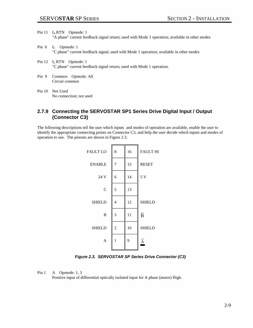
2.7.9 Connecting the SERVOSTAR SP1 Series Drive Digital Input / Output(Connector C3)
The following descriptions tell the user which inputs and modes of operation are available, enable the user toidentify the appropriate connecting points on Connector C3, and help the user decide which inputs and modes ofoperation to use. The pinouts are shown in Figure 2.3.
FAULT LO 8 16 FAULT HI
ENABLE 7 15 RESET
24 V 6 14 5 V
C 5 13
SHIELD 4 12 SHIELD
B 3 11 B
SHIELD 2 10 SHIELD
A 1 9 A
Figure 2.3. SERVOSTAR SP Series Drive Connector (C3)
Pin 1 A Opmode: 1, 3Positive input of differential optically isolated input for A phase (motor) High.

SECTION 2 - INSTALLATION SERVOSTAR SP SERIES
2-10
Pin 9 A Opmode: 1, 3Negative input of differential optically isolated input for A phase load (motor) Low.
Pin 2 Shield Opmode: 1, 3"A" Phase input cable shield connection. The shield pins provide termination points for cable shields. Toinsure there are no ground loops in the shield common, connect only one end, butt and insulate the otherend.
Pin 3 B Opmode: 1, 3Positive input of differential optically isolated for B phase load (motor) High.
Pin 11 B Opmode: 1, 3Negative input of differential optically isolated for B phase load (motor) Low.
Pin 10 Shield Opmode: 1, 3"B" Phase input cable shield connection
Pin 5 C Opmode: 1, 3Positive input of differential optically isolated for C phase load (motor) High.
Pin 13 C Opmode: 1, 3Negative input of differential optically isolated for C phase load (motor) Low.
Pin 4 Shield Opmode: 1, 3"C" Phase input cable shield connection
Pin 6 24 V (Plus or Minus) Opmode: AllProvides optocoupler signal common rail to 24 volts for systems choosing 24 V operation for the enableand reset inputs. This common rail can be connected to positive voltage (user sinks current) or to minusvoltages (user sources current). When this input is used, Pin 14 must not be used.
Pin 14 5 V (Plus or Minus) Opmode: AllProvides optocoupler signal common rail to 5 volts for systems choosing 5 V operation for the enable andreset inputs. This common rail can be connected to positive voltage (user sinks current) or to minusvoltages (user sources current). When this input is connected, Pin 6 must not be used.
Pin 7 Enable Opmode: AllAllows the SERVOSTAR SP Series Drive to be enabled or disabled without removing the main power.When a circuit is closed between Pin 7 and common (assuming Pin 6 is connected to +24 VDC or Pin 14 isconnected to +5 VDC, see Figure 2.5), the SERVOSTAR SP Series Drive will be put into the Drive-Upmode. Opening the circuit puts the SERVOSTAR SP Series Drive into the Inhibit mode (Green LEDindicated).
Pin 15 Reset Opmode: AllAllows any latched fault circuit except OVER-VOLTS or OVER-CORRECT faults to be reset by togglingPin 15 to common (Assuming Pin 6 is connected to +24 VDC or Pin 14 is connected to +5 VDC). SeeFigure 2.4.

SERVOSTAR SP SERIES SECTION 2 - INSTALLATION
2-11
ENABLE(PIN 7)
RESET(PIN 15)
+/- 24V(PIN 6)
+/- 5V(PIN 14)
Figure 2.4 Enable and Reset
Pin 8 Fault Output Low Side Opmode: AllOptically isolated fault output transistor’s source.
The transistor is normally on, indicating that no fault conditions exist.
Pin 16 Fault Output High Side Opmode: AllOptically isolated fault output transistor’s drain
The transistor is normally on, indicating that no fault conditions exist.
Pin 12 Shield Opmode: 1, 3Provided for connection of cable shields if necessary. Best shielding may result by connection at the other(source) end.
2.7.10 Connecting the Servostar SP2 Series Drive Digital Input/Output ( Connector C1)
See System Wiring Diagram C-97514 sheet 4 of 11 in Appendix H Drawings.

SECTION 2 - INSTALLATION SERVOSTAR SP SERIES
2-12
2.7.11 Connecting the Motor
B SERIES MOTORS have a thermostat switch wired to the resolver connector atthe motor.
BR SERIES MOTORS have a thermostat switch wired to the stator connector at themotor.
The motor thermostat switch is an automatic resetting device and should beconnected directly into a latched (locked out) power down type circuit.
Incorrect motor resolver or encoder phasing can cause erratic operation, runaway,or damage to the system.
The leads of the three-phase synchronous motor are brought out to Pins A, B, and C of the motor connector. Pin D isground for the motor. Refer to Figure 2.5 for pin connections.
A TOP B TOP C TOP
A BOTTOM B BOTTOM C BOTTOM
A B C
Figure 2.5. Motor Connections

SERVOSTAR SP SERIES SECTION 2 - INSTALLATION
2-13
Terminate Pins A, B, and C of the motor connector to Ma, Mb, and Mc, respectively, on the power terminal blocklocated on the front of the SERVOSTAR SP Series Drive amplifier. Terminate Pin D at the SERVOSTAR SPSeries Drive chassis ground screw. Refer to System Wiring Diagram C-97514 in Appendix H Drawings, and theappropriate motor HD (hook-up) drawing.
2.8 INSTALLATION CHECKLIST
Refer to SERVOSTAR SP Series Drive Wiring Diagram. See Appendix H.
Before applying power to the Power Supply and SERVOSTAR SP Series Drive, check the following items to ensureproper operation:
To prevent damage to the equipment, the motor and resolver, the AC line voltage,and the DC bus voltages must be connected as indicated by SERVOSTAR SPSeries Drive Wiring Diagram .
2.8.1 Checking the Motor Wiring
Disconnect both the motor stator connector from the motor. Using an ohmmeter, check the continuity of each motorstator lead between the motor stator connector pin and the SERVOSTAR SP Series Drive. The motor stator shouldbe connected according to SERVOSTAR SP Series Drive Wiring Diagram.
2.8.2 Checking the AC Line Voltages
Open the circuit breaker or remove the fuses in the Main AC lines that are connected to the Power Supply at La, Lb,and Lc. Remove Connector C7 from the Power Supply.
Apply only the AC main power. Use an AC voltmeter to check and record the 1- or 3-phase line-to-line voltage atthe circuit breaker or fuse holders. Remove power. Note the model number of the Power Supply and refer toAppendix C to confirm the correct Main AC voltage level.
Apply only the AC control power. Use an AC voltmeter to check and record the single-phase voltage at ConnectorC7 of the Power Supply. Remove power. Note the model number of the Power Supply and refer to Appendix E toconfirm correct Control AC voltage level.
If the voltage levels are within the specifications listed in Appendix E, proceed with the Check-Out procedure.
Close the circuit breaker or re-install the fuses for the Main AC input power. Re-install all connectors.
2.8.3 Checking the DC Bus Voltages
Allow sufficient time (after removing power from the system) for the voltageto bleed down before connecting or disconnecting wires at the bus.
Remove power.
SECTION 2 - INSTALLATION SERVOSTAR SP SERIES
2-14
Remove the Bus+ and Bus- leads from the Power Supply power terminal block. Remove mating Connector C1 fromthe Power Supply.
Apply power.
Check and record the Main DC Bus Voltage output at (+) with respect to (-) on the Power Supply terminal block.Check and record the unregulated DC voltage levels at Connector C1 of the Power Supply. They should be ± 15 to16 (pin 1 to pin 3) and + 7.5 to 8.5 (pin 4 to pin 3) VDC.
Remove power.
Note the model number of the Power Supply and confirm DC voltage levels.
If the voltage levels are within the specifications listed in Appendix E, proceed.
WAIT FOR THE BUS TO BLEED DOWN and reconnect the B(+) and B(-) leads to the power terminal block of thePower Supply. Be careful to reconnect the leads with the proper polarity. Re-install Connector C2 on the PowerSupply. It may take up to 2 minutes for the Bus to discharge to below 50V.
Failure to observe correct polarity will result in damage to the SERVOSTAR SPSeries Drive.

SERVOSTAR SP SERIES SECTION 3 - OPERATION
3-1
SECTION 3
OPERATION
3.1 INTRODUCTION
The information in this Section will enable you to become familiar with system components and their dependenceupon one another. Also, it will help you ensure each component is configured and functions properly. At this point,all safety stops and other precautions should be in place and working properly. Be prepared to stop the machine ifnecessary.
3.2 INITIAL START-UP
You should now be ready to supply power to test the servo systems functions and features. Work with only one axissection at a time. Confirm all other SERVOSTAR SP Series Drive amplifiers are inhibited, meaning the enablecircuits are open.
Incorrect servo-to-position loop phasing can cause excursion oscillations, orrunaways.
Appropriate precautions should be taken to stop the machine if necessary. Limit switches and safety devices shouldbe in place.
3.3 SEQUENCE OF OPERATIONS
This section contains a basic start-up sequence that should be followed the first time the servo system is initialized.READ THIS ENTIRE SECTION BEFORE PERFORMING ANY OF THESE PROCEDURES. When you applypower to the system, pay special attention to the LEDs on the SERVOSTAR SP Series Drive front panel. TheCONTROL VOLTS (green) LED should be illuminated. This indicates that the system is functioning properly.Should a FAULT (red) LED remain on for more than a instant, immediately disconnect power and consult Section 5- Troubleshooting. Apply power. Enable only one SERVOSTAR SP Series Drive. The Green Enabled LED should illuminate.
Observe the action of the machine. If the direction of the motor shaft rotation is reversed (motor shaft turns inthe wrong direction), remove power.
If the servo system performed properly, then read Section 4 - Maintenance for adjustments and other information thatmay be helpful in adapting your system to your own applications.
CAUTION

SECTION 3 - OPERATION SERVOSTAR SP SERIES
3-2

SERVOSTAR SP SERIES SECTION 4 - MAINTENANCE
4-1
SECTION 4
MAINTENANCE
4.1 INTRODUCTION
The information in this Section will enable you to maintain the systems components ensuring smooth, efficientoperation of the motor.
4.2 PREVENTATIVE MAINTENANCE
Preventative maintenance to this equipment must be performed by qualifiedpersonnel familiar with the construction, operation, and hazards involved withthe application.
Electronic components in this amplifier are static sensitive. Use properprocedures when handling component boards.
Preventative maintenance should be performed with the SERVOSTAR SP Series Drive system out of operation anddisconnected from all sources of power.
4.2.1 Transient Voltages
All transient-producing devices must be properly suppressed.
Solid state controls of the SERVOSTAR SP Series Drive may be affected by transient voltages. These voltages arein excess of the specified voltage for any given circuit. When these peak voltages occur, even for less than a second,permanent damage to the SERVOSTAR SP Series Drive can occur.
In order to help avoid transient voltages that may interfere with electronic circuit functions within the Power Supplyand SERVOSTAR SP Series Drive, all switched inductive devices or their wiring (solenoids, relay coils, startercoils, etc.) must be suppressed. A 220 ohm, 1/2 watt resistor in series with a 0.5 micro farad, 600 volt capacitor orequivalent is suggested.
CAUTION
CAUTION
NOTE

SECTION 4 - MAINTENANCE SERVOSTAR SP SERIES
4-2
4.2.2 Surge Current
Excessive current greater than that of the specified limits of the Power Supply and SERVOSTAR SP Series Drivecan cause permanent damage to the system. Current limiting means are recommended to protect from these currents.
If the short circuit inrush current generated by the power source is in excess of5000 amps RMS symmetrical current, an isolation transformer or line inductormust be utilized in the incoming power circuit. Failure to observe thisprecaution could result in damage to, or destruction of the Power Supply andSERVOSTAR SP Series Drive.
Input transformers step up or step down input voltage and can be either autotransformers or isolation transformers.Isolation transformers help eliminate the following:• Damaging AC line voltage transients reaching the Power Supply and SERVOSTAR SP Series Drive.• Damaging currents which may develop if a point inside the Power Supply or SERVOSTAR SP Series Drive
becomes grounded.
4.2.3 Electrical Noise
The low levels of energy in the SERVOSTAR SP Series Drive control circuits may cause them to be vulnerable toelectrical noise. Sources of electrical noise are those pieces of equipment that have large, fast changing voltages andcurrents when they switch on and off. These devices have the capability of inducing critical current and voltagetransients on their respective power lines. These transients must be accommodated for with noise immunityprovisions.
Electrical noise is prevented with the same methods as Surge Current and Transient Voltages. However, there areother methods of preventing electrical noise. Such as:• Maintain physical separation between electrical noise sources and the SERVOSTAR SP Series Drive
amplifier.• Maintain physical separation between electrical noise sources and the SERVOSTAR SP Series Drive control
wiring. This can be accomplished by using separate conduits or wiring trays for control wiring and powerwiring.
• Use twisted-pair wiring for control circuits of the SERVOSTAR SP Series Drive.• Follow good grounding practices when wiring the Power Supply and SERVOSTAR SP Series Drive. Be
careful not to create a grounding loop with multiple ground paths. Follow the NEC's provisions on grounding.
4.2.4 Radio Frequency Energy
This equipment generates radio frequency energy.
This equipment can radiate radio frequency energy and must be installed and used in accordance with thisinstallation and service manual in order to prevent possible interference with radio communications or otherelectronic equipment.
4.3 PERIODIC MAINTENANCE
CAUTION
NOTE

SERVOSTAR SP SERIES SECTION 4 - MAINTENANCE
4-3
Periodic maintenance must be performed by qualified personnel familiar with the construction, operation, andhazards involved with the SERVOSTAR SP Series Drive and its application. Power should be disconnected duringall maintenance procedures.
4.3.1 Ventilation
The Power Supply and SERVOSTAR SP Series Drive should be mounted vertically to allow maximum ventilationof the components. This configuration allows the heat generated by the components to vent through the top and draftin cooler air through the bottom. The top and bottom of the components are vented to allow this drafting to occur.These ventilation passages should be kept open. Inspect all fans on a regular basis.
4.3.2 Grounding Integrity
The method employed for grounding or insulating the equipment from ground should be checked to assure itsintegrity on a regular basis. This check should be performed with the power off and the testing equipment grounded.

SECTION 4 - MAINTENANCE SERVOSTAR SP SERIES
4-4

SERVOSTAR SP SERIES SECTION 5 - TROUBLESHOOTING
5-1
SECTION 5
TROUBLESHOOTING
5.1 INTRODUCTION
The information in this Section will enable you to isolate and resolve common system hardware problems. Thetroubleshooting methods in this manual isolate each component from the system until the problem is resolved.
5.2 FIELD SERVICEABILITY
Dangerous voltages exist in this equipment. Also, motor temperature mayexceed 100°°°°C. Extreme caution should be exercised when troubleshootingthis equipment. Only qualified individuals should attempt to install, setup,operate, or troubleshoot this equipment.
The SERVOSTAR SP Series Drive and Power Supply are designed to promote minimum down time situations. Dueto the compact package size and to the fact that there are few user-serviceable components on the modules, it isrecommended that they be replaced if they cease to function properly. Return the modules, in their entirety, toIndustrial Drives for repair.
The SERVOSTAR SP Series Drive modules may be interchanged, provided the following guidelines are adhered to:1. The SERVOSTAR SP Series Drive modules must be the same rating.2. The compensation header (if used) is loaded with the same values. (Modes 2 and 3 only).Before beginning the troubleshooting process, consider the following points:I. There are four (4) distinct areas within which a fault may occur:
A. External Interface (Circuitry external to, but connecting to, the SERVOSTAR SP Series Drive.)B. SERVOSTAR SP Series Drive Amplifier ModuleC. PA Power Supply Module
1. Main DC bus voltage2. Control DC bus voltages3. Shunt Regulator Regeneration Circuitry4. Soft-Start Circuitry
D. Motor1. Winding2. Feedback Device
II. There are only two (2) basic fault characteristics to be considered:A. The motor exhibits very low torque or is totally inoperative.B. The motor is erratic or exhibits an improper mode of operation.
CAUTION

SECTION 5 - TROUBLESHOOTING SERVOSTAR SP SERIES
5-2
5.3 SYMPTOMS AND CORRECTIONS
If the motor does not respond or responds in a manner other than with smooth operation, remove power andtroubleshoot the system with the following guidelines.
5.3.1 The Motor Exhibits Very Low Torque or is Totally Inoperative
Prerequisites for motor movement:1. The SERVOSTAR SP Series Drive and Power Supply must be wired correctly, per SERVOSTAR SP Series
Drive Wiring Diagram.2. All power must be present.3. The SERVOSTAR SP Series Drive must be in the Enable mode as indicated by the green LED.4. Fault circuits must not be activated. Fault modes are identified by red LED's located on the front of the
SERVOSTAR SP Series Drive and Power Supply modules.5. Input command must be present.
5.3.2 The Motor is Erratic or Exhibits an Improper Mode of Operation.
Prerequisites for proper motor operation:1. Proper grounding scheme must be provided. The motor ground wire should be connected as shown by
SERVOSTAR SP Series Drive Wiring Diagram.2. Motor armature leads must not be run in conduit or wire ducts with any signal carrying conductors.3. The feedback leads and motor armature leads must be wired according to SERVOSTAR SP Series Drive
Wiring Diagram.4. The motor system resolver must be set at its zero point.
5.3.3 SERVOSTAR SP Series Drive Status LED's
The status of the SERVOSTAR SP Series Drive modules is indicated by two (2) Green and four (4) Red LED's.The diagnostic information indicated by these LED's is listed as follows:• Approximately a half a second after all power is applied, the green CONTROL VOLTS LED on the front of
the SERVOSTAR SP Series Drive module should become illuminated to indicate that the Control AC lineinput voltage is applied.
• No fault (red) LED's should be illuminated.
The red short circuit LED is activated by protection circuitry with the power device. It will activate on an over-tempor shorted output load condition.
When the red OVER-CURRENT LED becomes illuminated, it indicates an over-current condition has occurred(usually due to excessive current command). The SERVOSTAR SP Series Drive will become latched in the Inhibitmode.
If the red OVER-VOLTS LED becomes illuminated, the SERVOSTAR SP Series Drive will become latched in theInhibit mode, indicating the presence of excessive main DC bus voltage.
When the red UNDER-VOLTS LED becomes illuminated, the SERVOSTAR SP Series Drive will be put into theInhibit mode (but not latched) indicating the main DC Bus is insufficient or absent.
The Outputs contacts located within the Power Supply power supply module will not be affected by any faultsoccurring within the SERVOSTAR SP Series Drive.
SERVOSTAR SP SERIES SECTION 5 - TROUBLESHOOTING
5-3
The green ENABLED LED must be illuminated (by energizing the remote enable while no drive faults exist) to getpower out of the SERVOSTAR SP Series Drive.
More diagnostic information about the SERVOSTAR SP Series Drive is listed in the Table 5.1.
5.3.4 Power Supply Amp Status LED's
The status of the Power Supply module is indicated by one (1) Green and one (1) Yellow LED's. (Not available onall models.) The diagnostic information indicated by these LED's is as follows:• Approximately 0.25 seconds after the main power is applied, the green DC BUS LED will become illuminated
to indicate the presence of voltage on the main DC bus capacitors and the Bus-Up output will turn on. Voltageindication may range in magnitude from over 300 VDC, during normal operation with AC line voltageapplied, to below 50 VDC when the line voltage is removed but the bus capacitors have not completelydischarged.
• The yellow REGEN LED (not available on all models) is for monitoring purposes only. When this LEDbecomes illuminated, the shunt regulator regeneration circuit is active. The Regen output will also turn onwhenever the shunt regulator is active.
• Faults occurring within the Power Supply will cause the Bus-Up output to turn off. (Not available on allmodels).
More diagnostic information about the Power Supply LED's is listed in Table 5.2.
5.3.5 SERVOSTAR SP Series Drive or Power Supply Reset Procedures
To reset the fault latches within the SERVOSTAR SP Series Drive and all fault latches within the Power Supplypower supply units, remove all AC line input voltage for at least five (5) minutes or until the power stage capacitorsare fully discharged. All other fault latches within the SERVOSTAR SP Series Drive amplifiers may be reset bytoggling the RESET input circuit to common or by removing and reapplying the input voltage as describedpreviously.
SECTION 5 - TROUBLESHOOTING SERVOSTAR SP SERIES
5-4
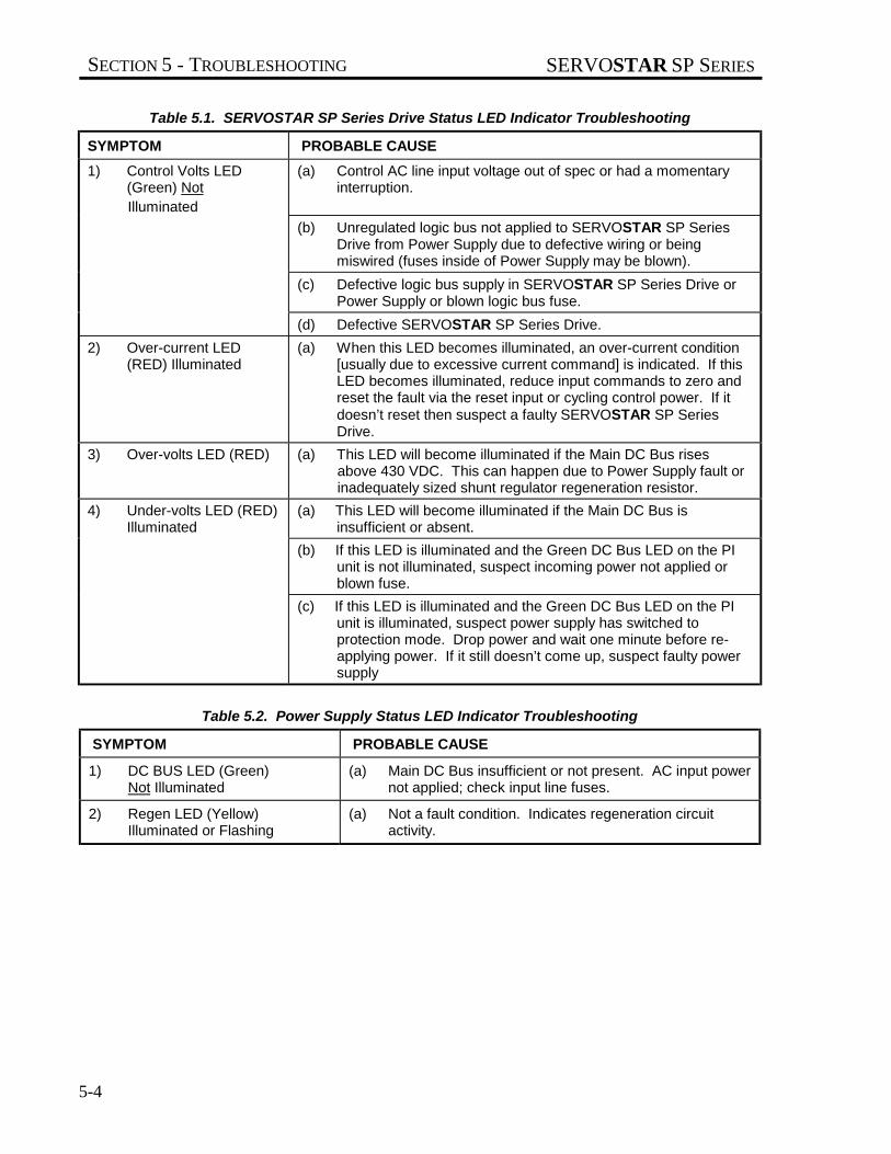
Table 5.1. SERVOSTAR SP Series Drive Status LED Indicator Troubleshooting
SYMPTOM PROBABLE CAUSE
1) Control Volts LED(Green) Not
Illuminated
(a) Control AC line input voltage out of spec or had a momentaryinterruption.
(b) Unregulated logic bus not applied to SERVOSTAR SP SeriesDrive from Power Supply due to defective wiring or beingmiswired (fuses inside of Power Supply may be blown).
(c) Defective logic bus supply in SERVOSTAR SP Series Drive orPower Supply or blown logic bus fuse.
(d) Defective SERVOSTAR SP Series Drive.
2) Over-current LED (RED) Illuminated
(a) When this LED becomes illuminated, an over-current condition[usually due to excessive current command] is indicated. If thisLED becomes illuminated, reduce input commands to zero andreset the fault via the reset input or cycling control power. If itdoesn’t reset then suspect a faulty SERVOSTAR SP SeriesDrive.
3) Over-volts LED (RED) (a) This LED will become illuminated if the Main DC Bus risesabove 430 VDC. This can happen due to Power Supply fault orinadequately sized shunt regulator regeneration resistor.
4) Under-volts LED (RED)Illuminated
(a) This LED will become illuminated if the Main DC Bus isinsufficient or absent.
(b) If this LED is illuminated and the Green DC Bus LED on the PIunit is not illuminated, suspect incoming power not applied orblown fuse.
(c) If this LED is illuminated and the Green DC Bus LED on the PIunit is illuminated, suspect power supply has switched toprotection mode. Drop power and wait one minute before re-applying power. If it still doesn’t come up, suspect faulty powersupply
Table 5.2. Power Supply Status LED Indicator Troubleshooting
SYMPTOM PROBABLE CAUSE
1) DC BUS LED (Green)Not Illuminated
(a) Main DC Bus insufficient or not present. AC input powernot applied; check input line fuses.
2) Regen LED (Yellow)Illuminated or Flashing
(a) Not a fault condition. Indicates regeneration circuitactivity.

SERVOSTAR SP SERIES APPENDIX A - WARRANTY INFORMATION
A-1
APPENDIX AWARRANTY INFORMATION
Kollmorgen Motion Technologies Group warrants that equipment, delivered by it to the Purchaser, will be of thekind and quality described in the sales agreement and/or catalog and that the equipment will be free of defects indesign, workmanship, and material.
The terms and conditions of this Warranty are provided with the product at the time of shipping or in advance uponrequest.

APPENDIX A - WARRANTY INFORMATION SERVOSTAR SP SERIES
A-2

SERVOSTAR SP SERIES APPENDIX B - REGIONAL SALES OFFICES
B-1
Kollmorgen is committed to quality customer service.Our goal is to provide the customer with information andresources as soon as they are needed. This one numberprovides order status and delivery information, productinformation and literature, and application and fieldtechncial assistance.
APPENDIX B
CUSTOMER SUPPORT
Note: If you are unaware of your local sales representa-tive, please contact us at the number below . Visit ourweb site for MotionLink software upgrades, technicalarticles, and the most recent version of our productmanuals.
Kollmorgen Customer Support Network203 Rock Road Suite A
Radford, VA 24141Phone: (888) 774-KCSN (5276)
Fax: (540) 639-1640 Inside SalesFax: (540) 639-1574 T echnical Suppor t
Email: [email protected]://www.Kollmorgen.com
APPENDIX B - REGIONAL SALES OFFICES SERVOSTAR SP SERIES
B-2
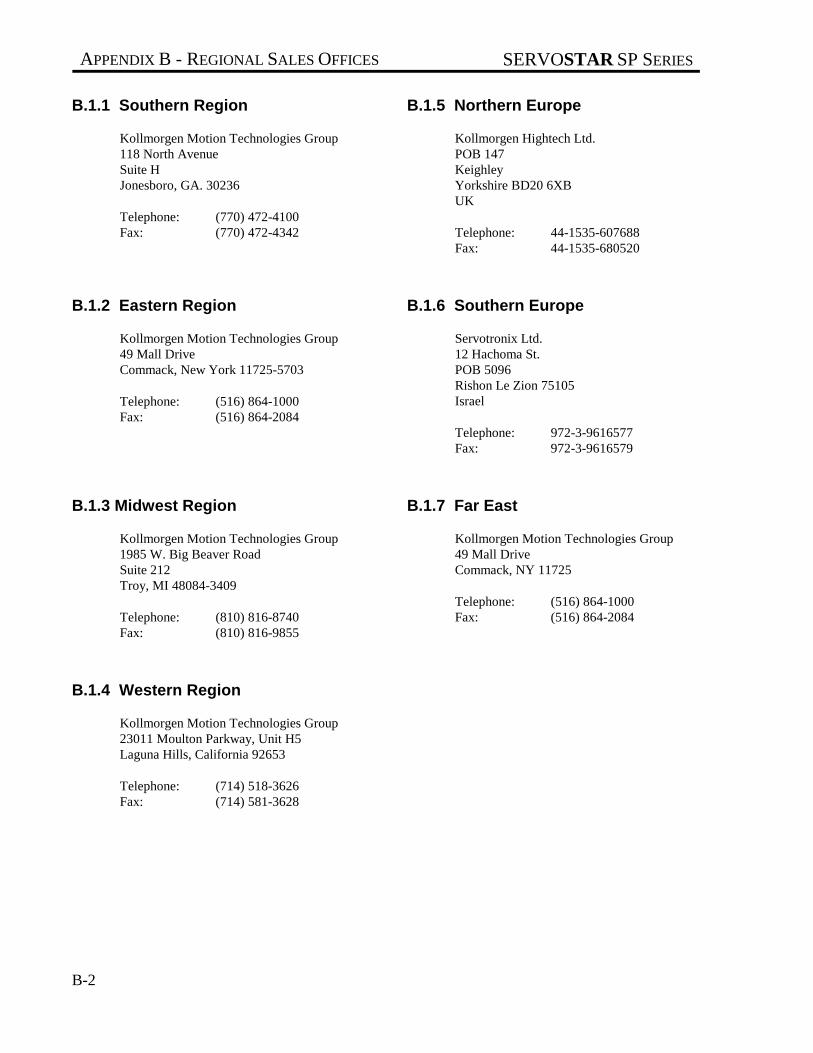
B.1.1 Southern Region
Kollmorgen Motion Technologies Group118 North AvenueSuite HJonesboro, GA. 30236
Telephone: (770) 472-4100Fax: (770) 472-4342
B.1.2 Eastern Region
Kollmorgen Motion Technologies Group49 Mall DriveCommack, New York 11725-5703
Telephone: (516) 864-1000Fax: (516) 864-2084
B.1.3 Midwest Region
Kollmorgen Motion Technologies Group1985 W. Big Beaver RoadSuite 212Troy, MI 48084-3409
Telephone: (810) 816-8740Fax: (810) 816-9855
B.1.4 Western Region
Kollmorgen Motion Technologies Group23011 Moulton Parkway, Unit H5Laguna Hills, California 92653
Telephone: (714) 518-3626Fax: (714) 581-3628
B.1.5 Northern Europe
Kollmorgen Hightech Ltd.POB 147KeighleyYorkshire BD20 6XBUK
Telephone: 44-1535-607688Fax: 44-1535-680520
B.1.6 Southern Europe
Servotronix Ltd.12 Hachoma St.POB 5096Rishon Le Zion 75105Israel
Telephone: 972-3-9616577Fax: 972-3-9616579
B.1.7 Far East
Kollmorgen Motion Technologies Group49 Mall DriveCommack, NY 11725
Telephone: (516) 864-1000Fax: (516) 864-2084
SERVOSTAR SP SERIES APPENDIX C - MODEL NUMBERS
C-1
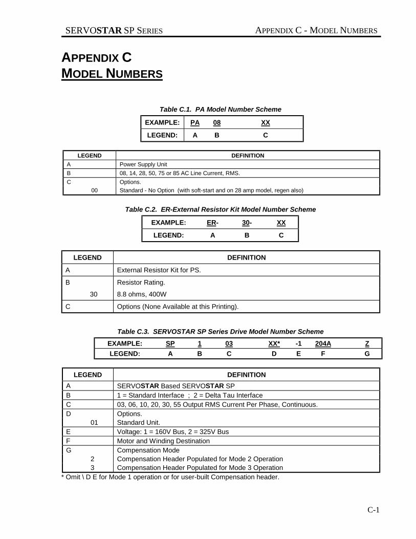
APPENDIX CMODEL NUMBERS
Table C.1. PA Model Number Scheme
EXAMPLE: PA 08 XX
LEGEND: A B C
LEGEND DEFINITION
A Power Supply Unit
B 08, 14, 28, 50, 75 or 85 AC Line Current, RMS.
C Options.
00 Standard - No Option (with soft-start and on 28 amp model, regen also)
Table C.2. ER-External Resistor Kit Model Number Scheme
EXAMPLE: ER- 30- XX
LEGEND: A B C
LEGEND DEFINITION
A External Resistor Kit for PS.
B Resistor Rating.
30 8.8 ohms, 400W
C Options (None Available at this Printing).
Table C.3. SERVOSTAR SP Series Drive Model Number Scheme
EXAMPLE: SP 1 03 XX* -1 204A Z
LEGEND: A B C D E F G
LEGEND DEFINITION
A SERVOSTAR Based SERVOSTAR SPB 1 = Standard Interface ; 2 = Delta Tau InterfaceC 03, 06, 10, 20, 30, 55 Output RMS Current Per Phase, Continuous.D Options.
01 Standard Unit.E Voltage: 1 = 160V Bus, 2 = 325V BusF Motor and Winding DestinationG Compensation Mode
2 Compensation Header Populated for Mode 2 Operation3 Compensation Header Populated for Mode 3 Operation
* Omit \ D E for Mode 1 operation or for user-built Compensation header.

APPENDIX C - MODEL NUMBERS SERVOSTAR SP SERIES
C-2
Table C.4. Compensation Card Model Designator
EXAMPLE: CMP- SP103 2204A 2
LEGEND: A B C D
LEGEND DEFINITION
A Compensation Card.
B Amplifier Base Model Number.
C Voltage, Motor, Winding, and Compensation Designator.
D Mode Designator
C.1 CABLE, BUS WIRE, AND MATING CONNECTOR KIT INFORMATIONExtra or spare bus wire and complete cable assemblies are available from KMTG.Mating connector kits are available from KMTG or may be purchased directly from the connector vendor.
C.2. CABLE MODEL NUMBER SCHEME FOR INDIVIDUAL CABLEIndividual cables can be provided by GC (Goldline Cable) Models. To assist in ordering, the model number schemefor an individual cable is as follows:
Table C.5. Cable Model Number Scheme for Individual Cable
(Bayonet Type Connector)
EXAMPLE: GC - M2 - 4/5 - 03
LEGEND: A B C D
LEGEND DEFINITION
A Goldline Cable With Bayonet-Type Connector (individual cable).
B Motor Power Cable with Mating Plug or Feedback/Option Cable.
M1 B, M-10X Motors.
M2 B, M-20X Motors (3 to 10 amp).
M2B B, M-20 X Motors (20 amp).
M4 B, M-40X Motors (3 to 20 amp).
M4B B, M - 40X Motors (30 amp.)
M6A B, M-60X-X-AX & BX Motors (up to 40 amps continuous).
M6B B, M -60X-X-AX & BX Motors (up to 65 amps continuous).
M8A B, M -80X-X-AX & BX Motors (up to 65 amps continuous).
M8B B, M -80X-X-AX & BX Motors (up to 115 amps continuous).
R System Resolver Only.
LEGEND DEFINITION

SERVOSTAR SP SERIES APPENDIX C - MODEL NUMBERS
C-3
C Amplifier Termination.
A Ring/Spade Lug Terminals.
N Not Terminated.
D Cable Length to Motor. 3 to 75 Meters in 3-Meter Increments.
Table C.6. Cable Model Number Scheme for Individual Cable
(Screw Type Connector)
EXAMPLE: GCA - M4 - 4/5 - 03
LEGEND: A B C D
LEGEND DEFINITION
A Goldline Cable with screw-type connector (individual cable).
B Motor Power Cable with Mating Plug or Feedback/Option Cable.
M4 B, M -40X Motors (up to 40 amps continuous).
M4B B, M-40X Motors (30 amps).
M6A B, M -60X Motors (up to 40 amps continuous).
M6B B, M -60X Motors (up to 65 amps continuous).
M8A B, M -80X Motors (up to 65 amps continuous).
M8B B, M -80X Motors (up to 115 amps continuous).
C Amplifier Termination.
A Ring/Spade Lug terminals.
N Not Terminated.
D Cable Length to Motor. 3 to 75 Meters in 3-Meter Increments.

APPENDIX C - MODEL NUMBERS SERVOSTAR SP SERIES
C-4

SERVOSTAR SP SERIES APPENDIX D - CONNECTOR KITS & TOOLS
D-1
APPENDIX DCONNECTOR KITS & TOOLS
D.1 INTRODUCTION
Mating connectors are customer furnished items which may be ordered either from Kollmorgen MotionTechnologies Group or purchased directly from the connector vendor. Ordering information is as follows:
Table D.1. SERVOSTAR SP Series Drive Connector Kit
CONNECTOR KIT Part Number: CK102
Connector Description Molex Part No. KMTG Part No.
C2 Connector Housing, 12Position Female
39-01-2125 A-83908-012
C3 Connector Housing, 16Position Female
39-01-2165 A-83908-016
C2, C3 PIN, Female,(18-24 AWG)
39-00-0039 A-83909-002
Table D.2. Connector Tools
CONNECTOR TOOLS (PINS, MINI FIT JR.) FROM MOLEX
Description EngineeringNumber
OrderNumber
Hand Crimping Tool HTR-60622 11-01-0122
Extractor Tool HT-60630A 11-03-0038
MOLEX TELEPHONE NUMBER: (708) 969-4550
Kollmorgen Motion Technologies Group supplies Connector Kit P/N SP1C100 with each SERVOSTAR SP SeriesDrive Module.

APPENDIX D - CONNECTOR KITS & TOOLS SERVOSTAR SP SERIES
D-2

SERVOSTAR SP SERIES APPENDIX E - SPECIFICATIONS
E-1
APPENDIX ESPECIFICATIONS
E.1 INTRODUCTION
The Specifications for the Power Supply and SERVOSTAR SP Series Drives are provided in this appendix.Derating information is also included for environments with high ambient temperatures. As a general rule, thefailure rate of solid state components doubles for every ten degrees Celsius rise in temperature. This exponentialfailure rate is strong incentive for lower ambient temperatures.
E.2 POWER SUPPLIES
The following information describes the power supplies used with SERVOSTAR SP Series Drives. They arestandard members of the SERVOSTAR family.
E.2.1 Logic Supply Module PA-LM
The Logic Supply Module is designed to supply power for up to two SERVOSTAR SP Series drives. It does notsupply Motor Bus Power. It is used where the application requires more than 4 axes of drives running from the samepower supply or where bus power is derived elsewhere.
E.2.2 Power Supply PA08xx
This modular power supply has two sections, a main dc bus, and logic power.
The main dc bus section consists of input line filters, three-phase diode bridge, bus caps, and soft-start circuitry (tolimit inrush currents). The main dc bus section is designed to operate from either 115 VAC single-phase or 230VAC three-phase input mains. A green LED indicates when there is voltage on the bus caps.
The logic power section consists of a universal input SMPS for generating the required +15 VDC and +7.5 VDCLogic Power for one or two SERVOSTAR SP Series Drive amplifiers. The SMPS input is connected to the LA andLB main dc bus input terminals.
E.2.3 Power Supply PA14xx and PA28xx
These modular power supplies have two sections, a main dc bus, and logic power.
The main dc bus section is designed to operate from 115VAC for the PA14 or 230 VAC three-phase for the PA28.Features of these power supply include:
• A green LED to indicate when there is voltage on the bus caps. • Relay output to indicate the power is energized and operating. • Soft-start circuitry (to limit inrush currents). • Internal/External Regen (shunt regulator) with a yellow LED indicator.
The power supply has a 40W rated internal resistor, for light duty applications. For heavier duty applications, ajumper on the front terminal block is removed and an external resistor is connected.
APPENDIX E - SPECIFICATIONS SERVOSTAR SP SERIES
E-2
The relay output is a normally open contact which closes upon application of power to the power supply and aftersoft-start is completed. The contacts will open if the internal Regen resistor or main heatsink becomes too hot, or ifthere is improper power supply output.
The logic power section consists of a 115VAC (PA14xx) or a 230V (PA28xx) input SMPS for generating therequired +15 VDC and +7.5 VDC Logic Power. The PA14xx can drive up to 2 SERVOSTAR SP Series Driveamplifiers. The PA28xx can drive up to 4 SERVOSTAR SP Series Drive amplifiers. The Regen resistor is fuseprotected.
E.2.4 Power Supply PA50xx / PA75xx / PA85xx
The PA50xx, PA75xx, and PA85xx Power Supply units are identical except that the 75 amp and 85 amp units havehigher power components and more capacitive filtering. Neither of the units have internal regeneration but each hasthe electronics internal and requires an external resistor.
The main dc bus section is designed to operate from 230 VAC three-phase input mains. Features of this powersupply include:
• A green LED to indicate when there is voltage on the bus caps. • Relay output to indicate the power is energized and operating. • Soft-start circuitry (to limit inrush currents). • External Regen (shunt regulator) with a yellow LED indicator. • A red fault LED indicator showing the softstart has not closed.
The relay output is a normally open contact which closes upon application of power to the power supply and aftersoft-start is completed. The contacts will open if the internal Regen resistor or main heatsink becomes too hot, or ifthere is improper power supply output. The logic power section consists of a 230V input SMPS for generating therequired +15 VDC and +7.5 VDC Logic Power for up to four SERVOSTAR SP Series Drive amplifiers. Up to 4amplifiers may be powered by this logic supply.

SERVOSTAR SP SERIES APPENDIX E - SPECIFICATIONS
E-3
Table E-1. SERVOSTAR Power Supply SpecificationsPower Supply Model PA08 PA28 PA50 PA75
Main Voltage (Vac) (line to line) 115 to 230 208 to 230 208 to 230 208 to 230
Input 1 Phase / 3 Phase 1/3 1/3 3 3
Power Frequency +15 - 5% 50/60
Main Rated current (amps) 8 14 @ 1 Phase28 @ 3 Phase
50 75
Input Current Max. current, 2 sec. (amps) 16 28 @ 1 Phase36 @ 3 Phase
75 115
Output Output volts (Nominal) 160/325 325 325 325
Power Output current 8/8 14/28 50 75
Logic Input Voltage (volts AC) 50/60 Hz 115 to 230 208 to 230 208 to 230 208 to 230
Power Input Input Current (amps Max.) 1 1 1 1
Logic Logic voltage (volts) 8
Power Logic current (amps) 2.2 4.4 4.4 4.4
Output 15V Voltage (volts) +/-15
15V Current (amps) 0.75 1.7 1.7 1.7
Protective Over temperature trip n/a 90 90 90
Functions Other Under volts, Over Temp, Softstart, Internal Fusing
Regen Regen trip voltage (on) (Vdc nom.) 390 390 390 390
Operation Regen off voltage (Vdc nom.) 375 375 375 375
Internal Peak current (amps) n/a 32 n/a n/a
Shunt Resistance (ohms) n/a 12.5 n/a n/a
Regulator Watts n/a 40 n/a n/a
External Peak current (amps) n/a 45 100 200
Shunt Minimum resistance (ohms) n/a 8.8 4.5 2.2
Regulator Watts n/a 400 1000 2000
Surge current (max. amps) 30 50 40 40
Soft Start Charge time (max. sec) 0.75 0.25 0.5 0.75
Internal heat dissipation (watts) 45 w 130 w 200 w 275 w
Operation temperature (°C) 0 to 45
Storage temperature (°C) -20 to 70
Environment Ambient humidity 10% to 90%
Atmosphere With no Corrosive gasses or dust
Altitude 3300 feet max. without derate
Vibration 0.5 g
Package Weight lb (kg) (Typical) 4.74 (2.16) 8.18 (3.72) 14.32 (6.51) 14.52 (6.6)
Height in (mm) (Max) 10.39 (264) 10.39 (264) 16 (406.4) 16 (406.4)
Width in (mm) (Max) 2.5 (63.5) 4.9 (124.4) 5.7 (144.6) 5.7 (144.6)
Depth in (mm) (Max) 7.95 (202) 7.95 (202) 11.2 (284) 11.2 (284)
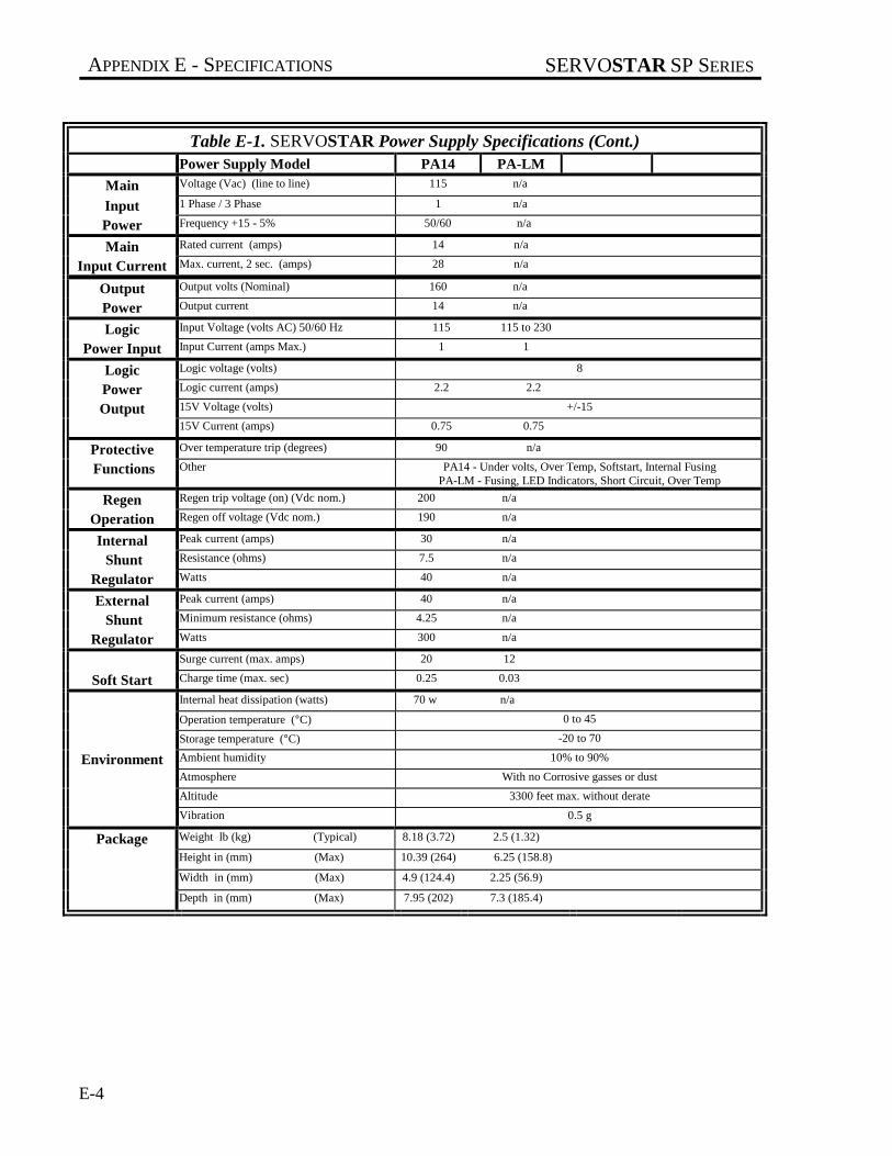
APPENDIX E - SPECIFICATIONS SERVOSTAR SP SERIES
E-4
Table E-1. SERVOSTAR Power Supply Specifications (Cont.)Power Supply Model PA14 PA-LM
Main Voltage (Vac) (line to line) 115 n/a
Input 1 Phase / 3 Phase 1 n/a
Power Frequency +15 - 5% 50/60 n/a
Main Rated current (amps) 14 n/a
Input Current Max. current, 2 sec. (amps) 28 n/a
Output Output volts (Nominal) 160 n/a
Power Output current 14 n/a
Logic Input Voltage (volts AC) 50/60 Hz 115 115 to 230
Power Input Input Current (amps Max.) 1 1
Logic Logic voltage (volts) 8
Power Logic current (amps) 2.2 2.2
Output 15V Voltage (volts) +/-15
15V Current (amps) 0.75 0.75
Protective Over temperature trip (degrees) 90 n/a
Functions Other PA14 - Under volts, Over Temp, Softstart, Internal FusingPA-LM - Fusing, LED Indicators, Short Circuit, Over Temp
Regen Regen trip voltage (on) (Vdc nom.) 200 n/a
Operation Regen off voltage (Vdc nom.) 190 n/a
Internal Peak current (amps) 30 n/a
Shunt Resistance (ohms) 7.5 n/a
Regulator Watts 40 n/a
External Peak current (amps) 40 n/a
Shunt Minimum resistance (ohms) 4.25 n/a
Regulator Watts 300 n/a
Surge current (max. amps) 20 12
Soft Start Charge time (max. sec) 0.25 0.03
Internal heat dissipation (watts) 70 w n/a
Operation temperature (°C) 0 to 45
Storage temperature (°C) -20 to 70
Environment Ambient humidity 10% to 90%
Atmosphere With no Corrosive gasses or dust
Altitude 3300 feet max. without derate
Vibration 0.5 g
Package Weight lb (kg) (Typical) 8.18 (3.72) 2.5 (1.32)
Height in (mm) (Max) 10.39 (264) 6.25 (158.8)
Width in (mm) (Max) 4.9 (124.4) 2.25 (56.9)
Depth in (mm) (Max) 7.95 (202) 7.3 (185.4)

SERVOSTAR SP SERIES APPENDIX E - SPECIFICATIONS
E-5
Table E.2. SERVOSTAR SP Series Drive Specifications
Amplifier Model SPx03 SPx06 SPx10 SPx20 SPx30 SPx55Voltage (Vdc) 125 to 360 125 to 360 125 to 360 295 to 360 295 to 360 295 to 360
Main Input power @ dc (kva) 0.63-1.4 1.26-2.79 1.96-4.34 8.68 13.33 24.45
Input Under volt trip (on power-up) 90 Vdc 90 Vdc 90 Vdc 255 Vdc 255 Vdc 255 Vdc
Power Under volt trip (normal) 90 Vdc 90 Vdc 90 Vdc 125 Vdc 125 Vdc 125 Vdc
Over volt trip 430 Vdc 430 Vdc 430 Vdc 430 Vdc 430 Vdc 430 Vdc
Control Logic Supply Voltage (Vdc)±5%
8 8 8 8 8 8
Input Logic Supply Current (Amp) 0.2 0.2 0.2 0.2 0.2 0.2
Power Analog Supply (Vdc) +15/-15 +15/-15 +15/-15 +15/-15 +15/-15 +15/-15
Analog Supply Current (mA) 200 320 330 450 420 530
Continuous Power (kw)(45°C ambient) @ 115 Vac 1ph
0.55 kw 1.1 kw 1.7 kw n/a n/a
Output Continuous Power (kw)(45°C ambient) @ 230 Vac 3ph
1.1 2.2 3.6 7.3 11 20
Power Rated output current (amps) 3 6 10 20 30 55
Max. current for 2 sec. (amps) 6 12 20 40 60 110
Rated PWM switchingfrequency (kHz)
16 16 16 8 8 8
Motor current ripple (kHz) 32 32 32 16 16 16
Form factor (rms/avg.) ≤1.01 ≤1.01 ≤1.01 ≤1.01 ≤1.01
Analog Analog Input Scaling(Modes 2 & 3)(Amps per volt)
0.85 1.70 2.83 5.66 8.48 15.55
Scaling Current Feedback Scaling(Amps per volt)
1.06 2.12 3.53 7.07 8.10 19.44
Internal Dissipation (Watts) 37 84 120 240 254 465
Heat LossOperating Temperature (°C) 0 to 45
Storage Temperature (°C) -20 to 70
Environ- Humidity (Non Condensing) 10% to 90%
Mental Atmosphere No Corrosive Gas or Dust
Altitude 3300 Feet Without Derating
Vibration 0.5g
Protective Over Current, Over Volts, Under volts, Control Volt Loss, Over Temp
Functions Over temperature trip (°C) 3 to 20 amp drives 118 °c and 90 °c for 30 and 55 amp drives
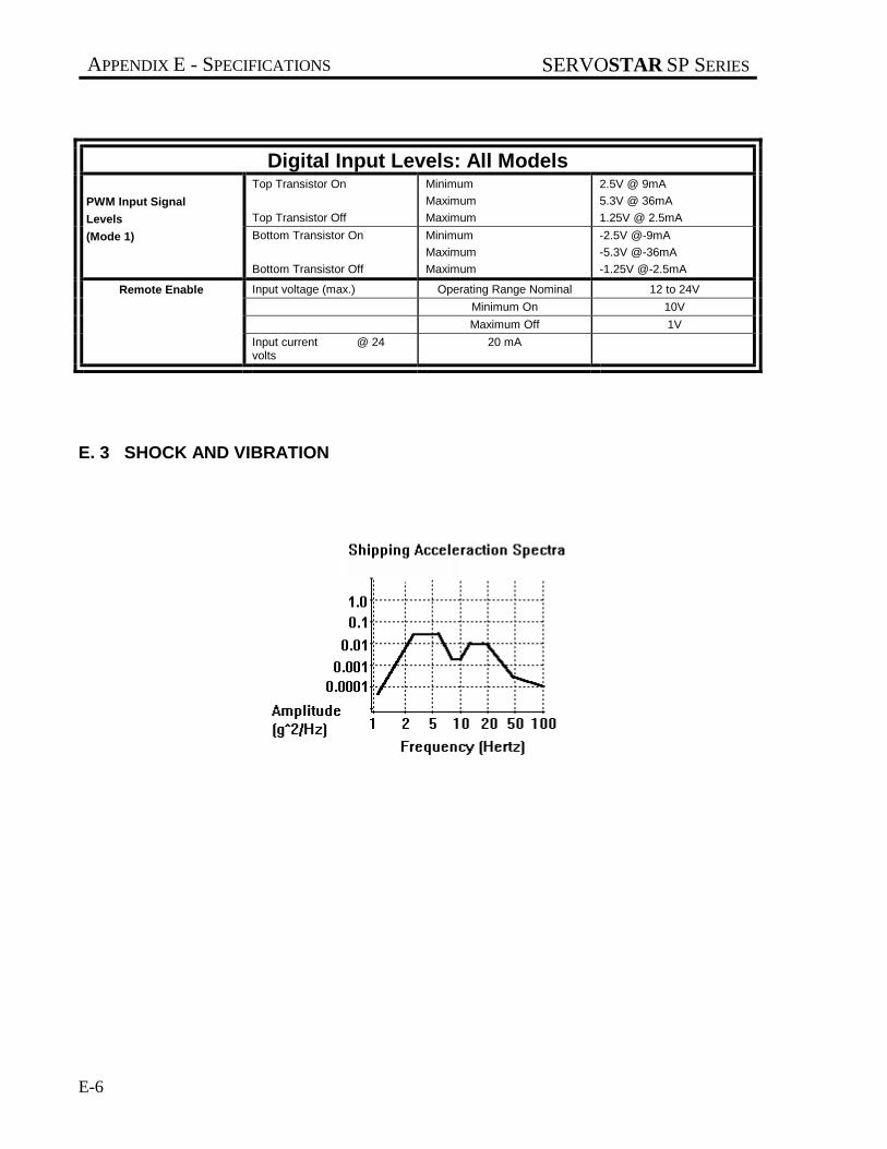
APPENDIX E - SPECIFICATIONS SERVOSTAR SP SERIES
E-6
Digital Input Levels: All ModelsTop Transistor On
Top Transistor Off
Minimum
Maximum
Maximum
2.5V @ 9mA
5.3V @ 36mA
1.25V @ 2.5mAPWM Input Signal
Levels
(Mode 1) Bottom Transistor On
Bottom Transistor Off
Minimum
Maximum
Maximum
-2.5V @-9mA
-5.3V @-36mA
-1.25V @-2.5mA
Input voltage (max.) Operating Range Nominal 12 to 24V
Minimum On 10V
Maximum Off 1V
Remote Enable
Input current @ 24volts
20 mA
E. 3 SHOCK AND VIBRATION

SERVOSTAR SP SERIES APPENDIX F - OPTIONS
F-1
APPENDIX FOPTIONS
Options are brought into existence from time to time to satisfy specific needs and to add versatility to the product.(Refer to the Model Number Schemes in Appendix C.)
The SERVOSTAR SP Series Drive may be ordered with various mechanical and electrical options, standard orcustom designed for particular applications. If a feature is desired which is not covered here, consult the KMTGRegional Sales Office for information on custom designed options.

APPENDIX F - OPTIONS SERVOSTAR SP SERIES
F-2

SERVOSTAR SP SERIES APPENDIX G - CURRENT LOOP COMPENSATION
G-1
APPENDIX GCURRENT LOOP COMPENSATION
G.1 INTRODUCTION
During mode 2 or mode 3 operation the SERVOSTAR SP Series Drive has internal current loops which must betuned to match a particular motor to a particular motor. Following is a list of the values to be used for this purpose.Three sets of components will be used in mode 2 operation and 1 set in mode 3 operation.
G.2 REQUIREMENTS
G.2.1 Operation Mode
Mode 1: Current loop external to SERVOSTAR SP Series Drive, closed by user.
Mode 2: Current Loop internal to SERVOSTAR SP Series Drive, done by Kollmorgen Motion Technologies Groupand shipped with unit or data supplied to user and user installs on supplied header/compensation board: required forthree current loops
Mode 3: internal to SERVOSTAR SP Series Drive, done by Kollmorgen Motion Technologies Group and shippedwith unit or data supplied to user and user installs on supplied header/compensation board, required for one currentloop
G.2.2 Compensation Calculation
Resistors ≤
(2.4x10⁶)x(SERVOSTAR SP Series Drive’s Cont. RMS Current Rating)x(Motor’s min. L-L inductance)
Capacitors = 1/(625 x Resistor)
These values for most motor combinations are already calculated and listed in Table G.1 at the end of Appendix G.
G.3 COMP HEADER
Pin Out
pin 1 to pin 16: mode selection jumper 1
pin 2 to pin 15: mode selection jumper 2
pin 3 to pin 14: “A phase” current loop resistor

APPENDIX G - CURRENT LOOP COMPENSATION SERVOSTAR SP SERIES
G-2
pin 4 to pin 13: “A phase” current loop capacitor
pin 5 to pin 12: “B phase” current loop resistor (not used with Mode 3)
pin 6 to pin 11: “B phase” current loop capacitor (not used with Mode 3)
pin 7 to pin 10: “C phase” current loop resistor (not used with Mode 3)
pin 8 to pin 9: “C phase” current loop capacitor (not used with Mode 3)
Mode Selection
Mode 1: jumper 1, jumper 2, comp header omitted
Mode 2: jumper 1 installed, jumper 2 omitted
Mode 3: jumper 1 installed, jumper 2 installed
Table G.1. Compensation Values
MOTOR RP'S "R" "C"
MODEL RATING K ohms uF
B-102A 3/6 AMPS 110kohm 0.015uf
B-102B 3/6 AMPS 25.5kohm 0.056uf
B-104A 3/6 AMPS 100kohm 0.015uf
B-104B 3/6 AMPS 51.1kohm 0.027uf
B-104B 6/12 AMPS 100kohm 0.015uf
B-106A 3/6 AMPS 130kohm 0.01uf
B-106B 6/12 AMPS 68.8kohm 0.022uf
B-106C 6/12 AMPS 47.5kohm 0.033uf
B-106C 10/20 AMPS 75kohm 0.018uf
MOTOR RP'S "R" "C"
MODEL RATING K ohms uF
B-202A 3/6 AMPS 536kohm 2700pf
B-202B 3/6 AMPS 201kohm 7500pf
B-202C 6/12 AMPS 150kohm 0.01uf
B-204A 3/6 AMPS 392kohm 3900pf
B-204B 6/12 AMPS 221kohm 6800pf
B-204C 10/20 AMPS 110kohm 0.01uf
B-204D 10/20 AMPS 90.9kohm 0.015uf
B-206A 3/6 AMPS 392kohm 3900pf
B-206B 6/12 AMPS 201kohm 7500pf
B-206B 10/20 AMPS 332kohm 4700pf

SERVOSTAR SP SERIES APPENDIX G - CURRENT LOOP COMPENSATION
G-3
MOTOR RP'S "R" "C"
MODEL RATING K ohms uF
B-206C 10/20 AMPS 110kohm 0.012uf
B-206D 20/40 AMPS 100kohm 0.015uf
B-206E 6/12 AMPS 130kohm 0.01uf
B-206E 10/20 AMPS 221ohm 6800pf
B-206F 3/6 AMPS 392kohm 3900pf
B-402C 10/20 AMPS 182kohm 8200pf
B-404A 6/12 AMPS 562kohm 2200pf
B-404B 10/20 AMPS 301kohm 4700pf
B-404C 20/40 AMPS 130kohm 0.01uf
B-404D 20/40 AMPS 249kohm 5600pf
B-404E 30/60 AMPS 150kohm 0.01uf
B-406A 10/20 AMPS 392kohm 3900pf
B-406B 20/40 AMPS 182kohm 8200pf
B-404C 30/60 AMPS 130kohm 0.01uf
B-404C 40/80 AMPS 182kohm 8200pf
B-406D 20/40 AMPS 357kohm 3900pf
B-602A 10/20 AMPS 332kohm 4700pf
B-602B 20/40 AMPS 130kohm 0.01uf
B-602C 20/40 AMPS 301kohm 4700pf
B-604A 20/40 AMPS 274kohm 5600pf
B-604B 30/60 AMPS 201kohm 6800pf
B-604C 40/80 AMPS 130kohm 0.01uf
B-604C 55/110 AMPS 182kohm 8200pf
B-604D 20/40 AMPS 453kohm 3300pf
MOTOR RP'S "R" "C"
MODEL RATING K ohms uF
B-606A 20/40 AMPS 301kohm 4700pf
B-606B 40/80 AMPS 182kohm 8200pf
B-606B 55/110 AMPS 249kohm 5600pf
B-606C 55/110 AMPS 121kohm 0.012uf
B-606D 30/40 AMPS 221kohm 6800pf
B-606E 40/80 AMPS 274kohm 5600pf
B-606F 20/40 AMPS 680kohm 2200pf
B-802A 30/60 AMPS 392kohm 3900pf
B-802A 40/80 AMPS 499kohm 3300pf
B-802B 40/80 AMPS 274kohm 5600pf
B-804A 40/80 AMPS 499kohm 3300pf
B-804B 55/110 AMPS 301kohm 4700pf
B-806A 55/110 AMPS 332kohm 3900pf
B-806C 30/60 AMPS 499kohm 3300pf
M-103A 3/6 AMPS 110kohm 0.015uf
M-105A 3/6 AMPS 100kohm 0.015uf
M-105B 3/6 AMPS 51.1kohm 0.027uf
M-105B 6/12 AMPS 100kohm 0.015uf
M-107A 3/6 AMPS 130kohm 0.01uf
M-107B 6/12 AMPS 68.8kohm 0.022uf
M-203A 3/6 AMPS 536kohm 2700pf
M-203B 3/6 AMPS 201kohm 7500pf
M-203C 6/12 AMPS 150kohm 0.01uf
M-205A 3/6 AMPS 392kohm 3900pf

APPENDIX G - CURRENT LOOP COMPENSATION SERVOSTAR SP SERIES
G-4
MOTOR RP'S "R" "C"
MODEL RATING K ohms uF
M-205B 6/12 AMPS 221kohm 6800pf
M-205C 10/20 AMPS 110kohm 0.01uf
M-207A 3/6 AMPS 392kohm 3900pf
M-207B 6/12 AMPS 201kohm 7500pf
M-207B 10/20 AMPS 332kohm 4700pf
M-403A 3/6 AMPS 536kohm 2700pf
M-403B 6/12 AMPS 249kohm 5600pf
M-403C 10/20 AMPS 182kohm 8200pf
M-405A 6/12 AMPS 562kohm 2200pf
M-405B 10/20 AMPS 301kohm 4700pf
M-405C 20/40 AMPS 130kohm 0.01uf
M-405D 20/40 AMPS 249kohm 5600pf
M-407A 10/20 AMPS 392kohm 3900pf
M-407B 20/40 AMPS 182kohm 8200pf
M-407C 30/60 AMPS 130kohm 0.01uf
M-407C 40/80 AMPS 182kohm 8200pf
M-407D 20/40 AMPS 357kohm 3900pf
M-603A 10/20 AMPS 332kohm 4700pf
M-603B 20/40 AMPS 130kohm 0.01uf
M-603C 20/40 AMPS 301kohm 4700pf
M-605A 20/40 AMPS 274kohm 5600pf
M-605B 30/60 AMPS 201kohm 6800pf
M-605C 40/80 AMPS 130kohm 0.01uf
M-605C 55/110 AMPS 182kohm 8200pf
MOTOR RP'S "R" "C"
MODEL RATING K ohms uF
M-605D 20/40 AMPS 453kohm 3300pf
M-607A 20/40 AMPS 301kohm 4700pf
M-607B 40/80 AMPS 182kohm 8200pf
M-607B 55/110 AMPS 249kohm 5600pf
M-607C 55/110 AMPS 121kohm 0.012uf
M-607E 30/60 AMPS 221kohm 6800pf
M-607E 40/80 AMPS 274kohm 5600pf
M-607F 20/40 AMPS 680kohm 2200pf
M-803A 30/60 AMPS 392kohm 3900pf
M-803A 40/80 AMPS 499kohm 3300pf
M-803B 40/80 AMPS 274kohm 5600pf
M-805A 40/80 AMPS 499kohm 3300pf
M-805B 55/110 AMPS 301kohm 4700pf
M-807A 55/110 AMPS 332kohm 3900pf
M-807C 30/60 AMPS 499kohm 3300pf
SERVOSTAR SP SERIES APPENDIX H - DRAWINGS
H-1
APPENDIX HDRAWINGS
SERVOSTAR SP Series 3 & 6 Amp Drive Outline and Dimension Drawing ................................................. H-3
SERVOSTAR SP Series 10 Amp Drive Outline and Dimension Drawing ...................................................... H-4
SERVOSTAR SP Series 20 Amp Drive Outline and Dimension Drawing ...................................................... H-5
SERVOSTAR SP Series 30 Amp Drive Outline and Dimension Drawing ...................................................... H-6
SERVOSTAR SP Series 55 Amp Drive Outline and Dimension Drawing ...................................................... H-7
Power Supply PA08xx Outline and Dimension Drawing.................................................................................. H-8
Power Supply PA14xx and PA28xx Outline and Dimension Drawing............................................................. H-9
Power Supplies PA50xx, PA75xx, and PA85xx Outline and Dimension Drawing .......................................... H-10
Power Supply PA08xx Simplified Schematic Diagram .................................................................................... H-11
Power Supplies PA14xx and PA28xx Simplified Schematic Diagram ............................................................. H-12
Power Supplies PA50xx, PA75xx, and PA85xx Simplified Schematic Diagram ............................................. H-13
SP1XXXX Simplified Schematic Diagram....................................................................................................... H-14
SERVOSTAR SP Series System Wiring - - (Dwg. No. C-97514 - 11 Sheets)............................................. H-15

APPENDIX H - DRAWINGS SERVOSTAR SP SERIES
H-2
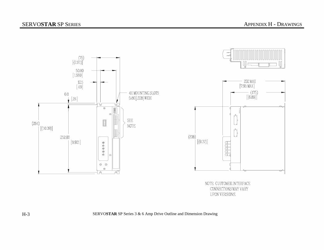
SERVOSTAR SP SERIES APPENDIX H - DRAWINGS
H-3 SERVOSTAR SP Series 3 & 6 Amp Drive Outline and Dimension Drawing
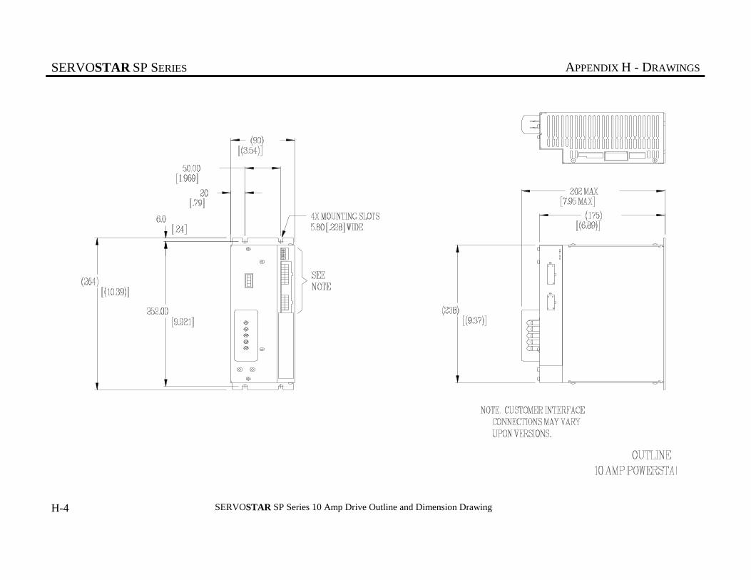
SERVOSTAR SP SERIES APPENDIX H - DRAWINGS
H-4 SERVOSTAR SP Series 10 Amp Drive Outline and Dimension Drawing

SERVOSTAR SP SERIES APPENDIX H - DRAWINGS
H-5 SERVOSTAR SP Series 20 Amp Drive Outline and Dimension Drawing
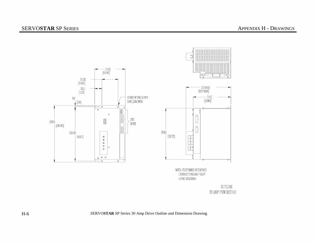
SERVOSTAR SP SERIES APPENDIX H - DRAWINGS
H-6 SERVOSTAR SP Series 30 Amp Drive Outline and Dimension Drawing

SERVOSTAR SP SERIES APPENDIX H - DRAWINGS
H-7 SERVOSTAR SP Series 55 Amp Drive Outline and Dimension Drawing

SERVOSTAR SP SERIES APPENDIX H - DRAWINGS
H-8 Power Supply PA08xx Outline and Dimension Drawing
6.0
252.00
(264)
50.00
[(2.50)]
[1.969]
[(.28)]
[.24]
[(10.39)]
[9.921]
(175)
202 MAX
(238)
(264)
[(6.89)]
[(10.39)]
[(9.37)]
[7.95 MAX]
4X MOUNTING SLOTS5.80 [.228] WIDE
(6.75)
(63.5)

SERVOSTAR SP SERIES APPENDIX H - DRAWINGS
H-9 Power Supplies PA14xx and PA28xx Outline and Dimension Drawing
202 MAX[7.95 MAX]
175[6.89]
264 [10.39]238 [9.37]
124.4[4.90]
50.00[1.969]
37.2[1.46]
252.00 [9.921]264 [10.39]
6.0 [.24]
4X MOUNTING SLOTS5.80 [.228] WIDE

SERVOSTAR SP SERIES APPENDIX H - DRAWINGS
H-10 Power Supplies PA50xx, PA75xx, and PA85xx Outline and Dimension Drawing
[6.53 MAX]
[4.000][(1.22)]
[.24]
[(11.10)]
[11.89]
[(7.01)]
[(10.39)]
[8.35 MAX]
4X MOUNTING SLOTS5.80 [.228] WIDE
(178)
101.60
166 MAX
282.00
(302)(264)
10
(31) 212 MAX

SERVOSTAR SP SERIES APPENDIX H - DRAWINGS
H-11 Power Supply PA08xx Simplified Schematic Diagram
1.5A
.1uf
.1uf
.1uf
.1uf
+1650uf
1
C1
+
4
C1
3C1
2C1
+
+
p
24ohm
3.5A
1.5A
.1uf
CONTROL CIRCUITRYINPUT MAINS
LA
LC
LB
CJF 1
1
90-260Vac
xxxxxx
xxxxx
1/97
1 1
1 1
BUS+
BUS-
COMMON
SOFT-START
40W universaltriple output switchingpower supply
SIMPLIFIED SCHEMATIC FOR PA08
+7.2V MIN.+8.5V MAX.
+14.2V MIN.+16.5V MAX.
-14.2V MIN.-16.5V MAX.
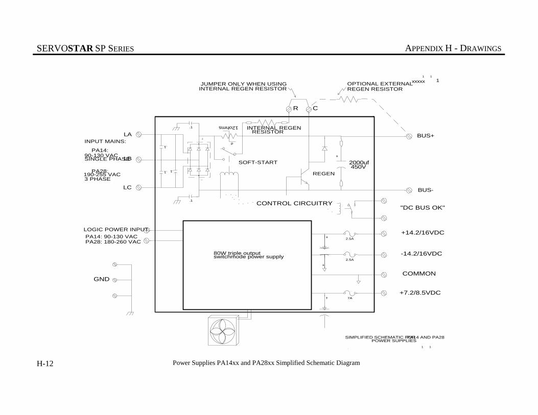
SERVOSTAR SP SERIES APPENDIX H - DRAWINGS
H-12 Power Supplies PA14xx and PA28xx Simplified Schematic Diagram
++
7A
2.5A
+
2.5A
.1
.1 .1
.1
.1
+
p
12ohms
LA
LB
LC
BUS+
BUS-
450V
3 PHASE
GND
R C
"DC BUS OK"
COMMON
OPTIONAL EXTERNALREGEN RESISTOR
SOFT-START
REGEN
INTERNAL REGEN RESISTOR
190-255 VAC
SIMPLIFIED SCHEMATIC FOR
CONTROL CIRCUITRY
CJF
JUMPER ONLY WHEN USINGINTERNAL REGEN RESISTOR
1
8/96
xxxxx
+14.2/16VDC
-14.2/16VDC
+7.2/8.5VDC
80W triple outputswitchmode power supply
PA14 AND PA28 POWER SUPPLIES
INPUT MAINS:
PA14:90-130 VACSINGLE PHASE
PA28:
LOGIC POWER INPUT:
PA14: 90-130 VACPA28: 180-260 VAC
2000uf
1 1
1 1

SERVOSTAR SP SERIES APPENDIX H - DRAWINGS
H-13 Power Supplies PA50xx, PA75xx, and PA85xx Simplified Schematic Diagram
10
++
7A
2.5A
+
2.5A
.1
.1 .1
.1
.1
+
LA
LB
LC
BUS+
BUS-
450V3 PHASE
GND
C
"DC BUS OK"
COMMON
REGEN RESISTOR
REGEN
SIMPLIFIED SCHEMATIC FOR
CONTROL CIRCUITRY
CJF
1
xxxxx
xxxxx
+14.2/16VDC
-14.2/16VDC
+7.2/8.5VDC
80W triple outputswitchmode power supply
POWER SUPPLIES
INPUT MAINS:
LOGIC POWER INPUT:
2000uf
B+
EXTERNAL
180-260 VAC
180-260 VAC
PA50 AND PA75
1/971 1
1 1
1

SERVOSTAR SP SERIES APPENDIX H - DRAWINGS
H-14 SP1XXXX Simplified Schematic Diagram
1000pf
150
150
.01
6
COMP
11COMP
7 COMP10
COMP
9COMP 8
COMP
11C3
390
150
3C3
150
390
13C3
5C3
7
C2
12
COMP
1
C5
.01
2C5
3C5
4C5
15
C3
9
C3
1
C3
5 COMP
6
C3
14
C3
7C3
12 C2
11 C2
150
16 C3
6 C2
5 C2
8 C3
1000pf
3C2
4C2
9
C2
10
C2
20K1
C2CW
20K
GNDIN OUT
133
16
16K
16K
390
390 12
C3
10
C3
133
15
8
C2
20K2
C2
390
20K
1331
GND
IN OUT
16K
16K
4
C3
3 COMP14
COMP
2
C3
GNDIN OUT
13COMP 4
COMP
133 2
+12V
-12V
+5V
N.C.
24V
5V
RESET
ENABLE
MS1 MS2
COM.
A
/A
B
/B
C
/C
CC_HI
CC_LO
COM.
FLT_HI
FLT_LO
MA
MB
MC
BUS+ BUS-
IC_RTN
IA_RTN
IC
IA
SHIELD
SHIELDS
PWMCIRCUITRY ISOLATED CURRENT
SENSOR CIRCUITRY
FPGA ISOLATED3 PHASEPOWERSTAGE
EARTH GND.
MOTORGND./SHIELD
96127
96127
CJF1 1
1 1
AC_HI
AC_LO
SPARE
"IG"
R1
R1
SIMPLIFIED SCHEMATIC FOR SP1XXXX
1/97
+15V
-15V
+8V

SERVOSTAR SP SERIES APPENDIX H - DRAWINGS
SP1
10-06-9789329 JDL 2
CONTROL VOLTSENABLED
OVER CURRENT
OVER VOLTAGE
OVER TEMPERATURE
UNDER VOLTAGE
(SEE NOTE 8, 9, 10)
RESET
ENABLE
+
- USER SUPPLIED
+5 or +24 VDC
SUPPLY
RTN
HI
RTNHI
"A" PHASE CURRENT FEEDBACK
"C" PHASECURRENT FEEDBACK
XXX DEC. PLACES ±.005 IN.XX DEC. PLACES ±.015 IN.
ANG. DIM. ±1 DEGREE DO NOT SCALE DWG. USE DIMENSIONS ONLY.
ALL DIMENSIONS ARE INCHES UNLESS OTHERWISE SPECIFIED.
UNLESS OTHERWISE SPECIFIED
CAD DWG
DWG. NO. SHEET 1 OF 11
DWG. NO. SHEET 1 OF 11
CH'K. BY:
DATE:
CROSS REF. NO:
JOB NO:
ECN NO.ISS. APP'D.APP'D.DATEDATE
FINISH:MATERIAL:
APP'D.DATE ECN NO.ECN NO. ISS.ISS.
4
4
3
3
2
2
1
1
DD
CC
BB
AA
UNLESS OTHERWISE SPECIFIED
REMOVE ALL BURRS AND
BREAK ALL SHARP EDGES.
ISSUE
DW'N. BY:
APP'D. BY:
PLOT SCALE ISSUE
C-
C-
97514 2
97514 2
SCM 05-08-97
1:1COPY CODE
SERVO STAR SP SERIES
SYSTEM WIRING
Kollmorgen Industrial DrivesRADFORD, VIRGINIA
C3 8
7
6
5
4
3
2
1
STATUS DISPLAY
USER I/O (USER INTERFACE SEE TEXT)
SP1 DRIVE
TYPICAL GOLDLINE
MOTOR CONNECTIONSNAME PIN MA
MB MC
CASE
A (BROWN)B (RED)
C (WHITE)
D (GREEN/YELLOW)
WARNING:TO PREVENT INJURY REPLACE MOTOR TERMINAL
BLOCK COVER AFTER WIRING
HI
LO
RETURN DIRECTLY TO POWER SUPPLY
EARTH
FEEDBACK DEVICE
A
B
C
MOTOR CABLE (SEE TEXT)
BUS +
BUS-
MA
MB
MC
C5
DRIVE INPUT POWER
(SEE SHEET 4-10)
1
2
3
4
16
15
14
13
12
11
10
9
C3 8
7
6
5
4
3
2
1
16
15
14
13
12
11
10
9
C2 6
5
4
3
2
1
12
11
10
9
8
7
"A" PHASE PWM INPUTA
A
"B" PHASE PWM INPUTB
B
"C" PHASE PWM INPUTC
C
"FAULT"
+5 VDC or
+24 VDC
MODE 1 CONNECTIONS
TO USER PROTECTION CIRCUIT SEE NOTE 1, 6 SHEET 10
H-15 SERVOSTAR SP Series System Wiring (Sheet 1 of 11)
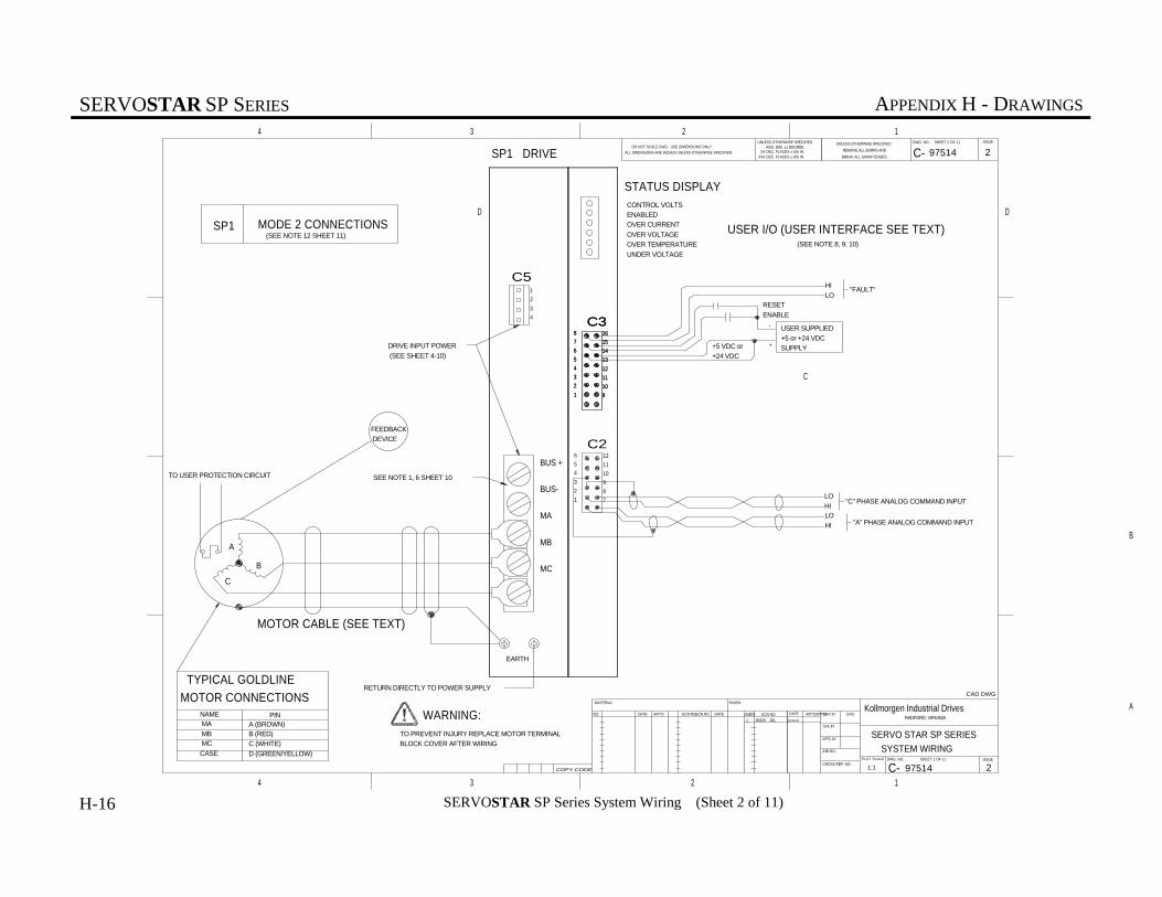
SERVOSTAR SP SERIES APPENDIX H - DRAWINGS
SP1
10-06-9789329 JDL 2
CONTROL VOLTSENABLED
OVER CURRENT
OVER VOLTAGE
OVER TEMPERATURE
UNDER VOLTAGE
(SEE NOTE 8, 9, 10)
RESET
ENABLE
+
- USER SUPPLIED
+5 or +24 VDC
SUPPLY
XXX DEC. PLACES ±.005 IN.XX DEC. PLACES ±.015 IN.
ANG. DIM. ±1 DEGREE DO NOT SCALE DWG. USE DIMENSIONS ONLY.
ALL DIMENSIONS ARE INCHES UNLESS OTHERWISE SPECIFIED.
UNLESS OTHERWISE SPECIFIED
CAD DWG
DWG. NO. SHEET 2 OF 11
DWG. NO. SHEET 2 OF 11
CH'K. BY:
DATE:
CROSS REF. NO:
JOB NO:
ECN NO.ISS. APP'D.APP'D.DATEDATE
FINISH:MATERIAL:
APP'D.DATE ECN NO.ECN NO. ISS.ISS.
4
4
3
3
2
2
1
1
DD
CC
BB
AA
UNLESS OTHERWISE SPECIFIED
REMOVE ALL BURRS AND
BREAK ALL SHARP EDGES.
ISSUE
DW'N. BY:
APP'D. BY:
PLOT SCALE ISSUE
C-
C-
97514 2
97514 21:1COPY CODE
SERVO STAR SP SERIES
SYSTEM WIRING
Kollmorgen Industrial DrivesRADFORD, VIRGINIA
C3 8
7
6
5
4
3
2
1
STATUS DISPLAY
USER I/O (USER INTERFACE SEE TEXT)
SP1 DRIVE
TYPICAL GOLDLINE
MOTOR CONNECTIONSNAME PIN MA
MB MC
CASE
A (BROWN)B (RED)
C (WHITE)
D (GREEN/YELLOW)
WARNING:TO PREVENT INJURY REPLACE MOTOR TERMINAL
BLOCK COVER AFTER WIRING
HI
LO
RETURN DIRECTLY TO POWER SUPPLY
EARTH
FEEDBACK
DEVICE
A
B
C
MOTOR CABLE (SEE TEXT)
BUS +
BUS-
MA
MB
MC
C5
DRIVE INPUT POWER
(SEE SHEET 4-10)
1
2
3
4
16
15
14
13
12
11
10
9
C3 8
7
6
5
4
3
2
1
16
15
14
13
12
11
10
9
C2 6
5
4
3
2
1
12
11
10
9
8
7
"FAULT"
+5 VDC or
+24 VDC
MODE 2 CONNECTIONS
"C" PHASE ANALOG COMMAND INPUT
"A" PHASE ANALOG COMMAND INPUT
LO
HILO
HI
(SEE NOTE 12 SHEET 11)
TO USER PROTECTION CIRCUIT SEE NOTE 1, 6 SHEET 10
H-16 SERVOSTAR SP Series System Wiring (Sheet 2 of 11)

SERVOSTAR SP SERIES APPENDIX H - DRAWINGS
10-06-9789329 JDL 2
SP1
LOHI
CURRENT COMMAND INPUT
CONTROL VOLTSENABLED
OVER CURRENT
OVER VOLTAGE
OVER TEMPERATURE
UNDER VOLTAGE
(SEE NOTE 8, 9, 10 SHEET 10)RESET
ENABLE
+
- USER SUPPLIED
+5 or +24 VDC
SUPPLY
XXX DEC. PLACES ±.005 IN.XX DEC. PLACES ±.015 IN.
ANG. DIM. ±1 DEGREE DO NOT SCALE DWG. USE DIMENSIONS ONLY.
ALL DIMENSIONS ARE INCHES UNLESS OTHERWISE SPECIFIED.
UNLESS OTHERWISE SPECIFIED
CAD DWG
DWG. NO. SHEET 3 OF 11
DWG. NO. SHEET 3 OF 11
CH'K. BY:
DATE:
CROSS REF. NO:
JOB NO:
ECN NO.ISS. APP'D.APP'D.DATEDATE
FINISH:MATERIAL:
APP'D.DATE ECN NO.ECN NO. ISS.ISS.
4
4
3
3
2
2
1
1
DD
CC
BB
AA
UNLESS OTHERWISE SPECIFIED
REMOVE ALL BURRS AND
BREAK ALL SHARP EDGES.
ISSUE
DW'N. BY:
APP'D. BY:
PLOT SCALE ISSUE
C-
C-
97514 2
97514 21:1COPY CODE
SERVO STAR SP SERIES
SYSTEM WIRING
Kollmorgen Industrial DrivesRADFORD, VIRGINIA
C3 8
7
6
5
4
3
2
1
STATUS DISPLAY
USER I/O (USER INTERFACE SEE TEXT)
SP1 DRIVE
TYPICAL GOLDLINE
MOTOR CONNECTIONSNAME PIN MA
MB MC
CASE
A (BROWN)B (RED)
C (WHITE)
D (GREEN/YELLOW)
WARNING:TO PREVENT INJURY REPLACE MOTOR TERMINAL
BLOCK COVER AFTER WIRING
HI
LO
RETURN DIRECTLY TO POWER SUPPLY
EARTH
FEEDBACK
DEVICE
A
B
C
MOTOR CABLE (SEE TEXT)
BUS +
BUS-
MA
MB
MC
C5
DRIVE INPUT POWER
(SEE SHEET 4)
1
2
3
4
16
15
14
13
12
11
10
9
C3 8
7
6
5
4
3
2
1
16
15
14
13
12
11
10
9
C2 6
5
4
3
2
1
12
11
10
9
8
7
"H1" COMMUTATION SIGNALH1
H1
"H2" COMMUTATION SIGNALH2
H2
"H3" COMMUTATION SIGNALH3
H3
"FAULT" (SEE NOTE 13)
+5 VDC or
+24 VDC
MODE 3 CONNECTIONS
(SEE NOTE 11 SHEET 10)
TO USER PROTECTION CIRCUIT
SEE NOTE 12 SHEET 11
SEE NOTE 1,6 SHEET 10
H-17 SERVOSTAR SP Series System Wiring (Sheet 3 of 11)

SERVOSTAR SP SERIES APPENDIX H - DRAWINGS
TO CONTROLLER
+5v POWERPOWER34
REFERENCE VOLTAGECOMMON33
PHASE C TOP COMMANDCOMMAND31
PHASE B TOP COMMANDCOMMAND29
PHASE A TOP COMMANDCOMMAND27
AMPLIFIER FAULTFEEDBACK26
AMPLIFIER ENABLECOMMAND25
1 OF 4 FAULT CODE BITSFEEDBACK
PHASE B ACTUAL CURRENT DATAFEEDBACK24
PHASE A ACTUAL CURRENT DATAFEEDBACK23
A/D CONVERTER STROBECOMMAND22
A/D CONVERTER CLOCKCOMMAND21
20
1 OF 4 FAULT CODE BITSFEEDBACK19
+5v POWERPOWER16
REFERENCE VOLTAGECOMMON15
PHASE C TOP COMMANDCOMMAND13
PHASE B TOP COMMANDCOMMAND11
PHASE A TOP COMMANDCOMMAND9
AMPLIFIER FAULTFEEDBACK8
AMPLIFIER ENABLECOMMAND7
PHASE B ACTUAL CURRENT DATAFEEDBACK6
PHASE A ACTUAL CURRENT DATAFEEDBACK5
A/D CONVERTER STROBECOMMAND4
A/D CONVERTER CLOCKCOMMAND3
1 OF 4 FAULT CODE BITSFEEDBACK2
1 OF 4 FAULT CODE BITSFEEDBACK1
DESCRIPTIONFUNCTIONPIN#
PIN OUT DEFINITION
10-06-9789329 JDL 2
CONTROL VOLTSENABLED
OVER CURRENT
OVER VOLTAGE
OVER TEMPERATURE
UNDER VOLTAGE
(SEE NOTE 8, 9, 10)
XXX DEC. PLACES ±.005 IN.XX DEC. PLACES ±.015 IN.
ANG. DIM. ±1 DEGREE DO NOT SCALE DWG. USE DIMENSIONS ONLY.
ALL DIMENSIONS ARE INCHES UNLESS OTHERWISE SPECIFIED.
UNLESS OTHERWISE SPECIFIED
CAD DWG
DWG. NO. SHEET 2 OF 11
DWG. NO. SHEET 4 OF 11
CH'K. BY:
DATE:
CROSS REF. NO:
JOB NO:
ECN NO.ISS. APP'D.APP'D.DATEDATE
FINISH:MATERIAL:
APP'D.DATE ECN NO.ECN NO.ISS.ISS.
4
4
3
3
2
2
1
1
DD
CC
BB
AA
UNLESS OTHERWISE SPECIFIED
REMOVE ALL BURRS AND
BREAK ALL SHARP EDGES.
ISSUE
DW'N. BY:
APP'D. BY:
PLOT SCALE ISSUE
C-
C-
97514 2
97514 21:1COPY CODE
SERVO STAR SP SERIES
SYSTEM WIRING
Kollmorgen Industrial DrivesRADFORD, VIRGINIA
STATUS DISPLAY
USER I/O (USER INTERFACE SEE TEXT)
SP2 DRIVE
TYPICAL GOLDLINE
MOTOR CONNECTIONSNAME PIN MA
MB MC
CASE
A (BROWN)B (RED)
C (WHITE)
D (GREEN/YELLOW)
WARNING:TO PREVENT INJURY REPLACE MOTOR TERMINAL
BLOCK COVER AFTER WIRING
RETURN DIRECTLY TO POWER SUPPLY
EARTH
FEEDBACK
DEVICE
A
B
C
MOTOR CABLE (SEE TEXT)
BUS +
BUS-
MA
MB
MC
C5
DRIVE INPUT POWER
(SEE SHEET 4-10)
1
2
3
4
SP2 CONNECTIONS
TO USER PROTECTION CIRCUIT SEE NOTE 1, 6 SHEET 10
H-18 SERVOSTAR SP Series System Wiring (Sheet 4 of 11)

SERVOSTAR SP SERIES APPENDIX H - DRAWINGS
I/O C
ON
NE
CTO
R(S
) SE
E S
HE
ETS
1 T
O 4
F3
F2
10-06-9789329 JDL 2
CONTROL VOLTS
ENABLED
OVER CURRENTOVER VOLTAGE
OVER TEMPERATURE
UNDER VOLTAGE
STATUS DISPLAY
NOTES:-1 FOR SINGLE PHASE OPERATION, INPUT POWER
MUST BE WIRED TO "LA" AND "LB" OR LOGIC SUPPLY WILL NOT FUNCTION.
K
SEE NOTE 7B
ON SHEET 11
SEE NOTE 6, & 7B
ON SHEET 11
PA08: 115-230 VAC NOMINAL INPUT VOLTAGE
SEE NOTE 4 ON SHEET 11
1
2
3
4
1
2
3
4
EARTH GROUND
USER SUPPLIED INPUT POWER
POWER TO
DRIVE MOUNTED
LEFT OF POWER SUPPLY
MAIN BUS
INPUT
POWER
SELECT FUSES PER
POWER SUPPLY RATING.
SEE NOTE 3 ON SHEET 10
F1
EARTH GROUNDLOW INDUCTANCE
16 AWG
HIGH VOLTAGE MAY EXIST UP TO 5 MINUTES
AFTER POWER HAS BEEN REMOVED!
WARNING:THE SERVO STAR SYSTEM OPERATES WITH VOLTAGES
AS HIGH AS 230 VAC AND 400 VDC. USE CAUTIONAND REFER INSTALLATION AND TROUBLESHOOTING
TO QUALIFIED PERSONNEL ONLY! ALWAYS REPLACE
TERMINAL COVERS AFTER SERVICING.
WARNING:
+15 VDC INPUT-15 VDC INPUT
DC COMMON
+8 VDC INPUT
+15 VDC SUPPLY-15 VDC SUPPLY
DC COMMON
+8 VDC SUPPLY
1
23
4
DRIVEPOWER SUPPLYPIN
C5, C7
CONNECTIONS
1
2
3
4
TO OTHER DRIVE
MOUNTED RIGHT
OF POWER SUPPLY
SP1 OR SP2 DRIVEPA08XX POWER SUPPLY
LOW INDUCTANCE
C5C7
BUS +
BUS-
MA
MB
MC
BUS +
BUS-
LA
LB
LC
RADFORD, VIRGINIA
Kollmorgen Industrial Drives
SERVO STAR SP SERIES
SYSTEM WIRING
COPY CODE 1:1 296675
297514
C-
C-
ISSUEPLOT SCALE
APP'D. BY:
DW'N. BY:
ISSUE
BREAK ALL SHARP EDGES.
REMOVE ALL BURRS AND
UNLESS OTHERWISE SPECIFIED
AA
B B
C C
D D
1
1
2
2
3
3
4
4
ISS. ISS.ECN NO. ECN NO.DATE APP'D.
MATERIAL: FINISH:
DATE DATEAPP'D. APP'D.ISS. ECN NO.
JOB NO:
CROSS REF. NO:
DATE:
CH'K. BY:
DWG. NO. SHEET 5 OF 11
DWG. NO. SHEET 4 OF 11
CAD DWG
UNLESS OTHERWISE SPECIFIED DO NOT SCALE DWG. USE DIMENSIONS ONLY.
ALL DIMENSIONS ARE INCHES UNLESS OTHERWISE SPECIFIED.ANG. DIM. ±1 DEGREE
XX DEC. PLACES ±.015 IN.XXX DEC. PLACES ±.005 IN.
SEE NOTE 1
WARNING:READ ALL NOTES, WARNINGS, AND CAUTIONS!
The ServoSTAR Product line is modular in construction,
There are several power supply units and many other wiring
options. Some of the information may not be pertainent
to all applications.
SEE NOTE 7A ON SHEET 11
H-19 SERVOSTAR SP Series System Wiring (Sheet 5 of 11)

SERVOSTAR SP SERIES APPENDIX H - DRAWINGS
I/O C
ON
NE
CTO
R(S
) SE
E S
HE
ETS
1 T
O 4
10-06-9789329 JDL 2
CONTROL VOLTS
ENABLED
OVER CURRENT
OVER VOLTAGEOVER TEMPERATURE
UNDER VOLTAGE
STATUS DISPLAY
SEE PAGE 4 & 6
(SEE NOTE 2)
SEE NOTE 7B
ON SHEET 11
SEE NOTES 6, & 7B
ON SHEET 11
R
C
SEE INSTALLATION
INSTRUCTIONS IN TEXT
SEE INSTALLATION
INSTRUCTIONS IN TEXT
AC LOGIC POWER IN
NOT USED
AC LOGIC POWER IN
1
2
3
NOTESFUNCTIONPIN
C8
CONNECTIONS12
3
LOGIC INPUT
VOLTAGE
(SEE SPEC'SAND TEXT)
1
2
3
C8
C61
2
1
2
3
4
1
2
3
4
EARTH GROUND
POWER TO
DRIVES MOUNTED
LEFT OF POWER SUPPLY
(SEE NOTE 2)
EARTH GROUNDLOW INDUCTANCE
CAUTION:
NOTES:-1 ATTEMPTING TO ENABLE DRIVE BEFORE THIS BUS OK BECOMES ACTIVE MAY CAUSE POWER SUPPLY
TO NOT BECOME ACTIVE.
-2 UP TO 4 DRIVES MAY BE MOUNTED TO EITHER SIDE OF
POWER SUPPLY (SEE MANUAL) (SEE NOTE 5, SHEET 10).
DC BUS OK(SEE TEXT)
CAUTION:
(SEE NOTE 1)
16 AWG
HIGH VOLTAGE MAY EXIST UP TO 5 MINUTES
AFTER POWER HAS BEEN REMOVED!
WARNING:THE SERVO STAR SYSTEM OPERATES WITH VOLTAGES
AS HIGH AS 230 VAC AND 400 VDC. USE CAUTION
AND REFER INSTALLATION AND TROUBLESHOOTING
TO QUALIFIED PERSONNEL ONLY! ALWAYS REPLACE
TERMINAL COVERS AFTER SERVICING.
WARNING:
+15 VDC INPUT-15 VDC INPUT
DC COMMON
+8 VDC INPUT
+15 VDC SUPPLY-15 VDC SUPPLY
DC COMMON
+8 VDC SUPPLY
1
23
4
DRIVEPOWER SUPPLYPIN
C5, C7
CONNECTIONS
DC BUS OK
DC BUS OK
12
NOTESFUNCTIONPIN
1
2
3
4
C6
CONNECTIONS12
TO OTHER DRIVES
MOUNTED RIGHT
OF POWER SUPPLY
(SEE NOTE 3)
SP1 OR SP2 DRIVEPA14XX or PA28XX POWER SUPPLY
LOW INDUCTANCE
C5C7
BUS +
BUS-
MA
MB
MC
BUS +
BUS-
LA
LB
LC
RADFORD, VIRGINIA
Kollmorgen Industrial Drives
SERVO STAR SP SERIES
SYSTEM WIRING
COPY CODE 1:1 297514
297514
C-
C-
ISSUEPLOT SCALE
APP'D. BY:
DW'N. BY:
ISSUE
BREAK ALL SHARP EDGES.
REMOVE ALL BURRS AND
UNLESS OTHERWISE SPECIFIED
AA
B B
C C
D D
1
1
2
2
3
3
4
4
ISS. ISS.ECN NO. ECN NO.DATE APP'D.
MATERIAL: FINISH:
DATE DATEAPP'D. APP'D.ISS. ECN NO.
JOB NO:
CROSS REF. NO:
DATE:
CH'K. BY:
DWG. NO. SHEET 6 OF 11
DWG. NO. SHEET 6 OF 11
CAD DWG
UNLESS OTHERWISE SPECIFIED DO NOT SCALE DWG. USE DIMENSIONS ONLY.
ALL DIMENSIONS ARE INCHES UNLESS OTHERWISE SPECIFIED.ANG. DIM. ±1 DEGREE
XX DEC. PLACES ±.015 IN.XXX DEC. PLACES ±.005 IN.
SEE NOTE 7A
ON SHEET 11
H-20 SERVOSTAR SP Series System Wiring (Sheet 6 of 11)

SERVOSTAR SP SERIES APPENDIX H - DRAWINGS
10-06-9789329 JDL 2
TERMINAL "R" AND "C".
-5 WHEN USING EXTERNAL REGEN RESISTOR JUMPER ON TERMINALS "R" AND "C"
MUST BE REMOVED.
SEE NOTE 4 AND 5
R
C
BUS +
BUS-
LA
LB
LC
FAULT CONTACTS-SEE NOTE 1
NORMALLY OPEN
AUXILIARY
CONTACT FROMMAIN POWER
CONTACTOR.
L3L2
L1
SYSTEM POWER
* TRANSFORMER MAY BE
OMITTED IF CORRECT
VOLTAGE SOURCE IS
AVAILABLE.
SEE SHEET 11
NOTE 3
115 VAC only for PA14XX
230 VAC only for PA28XX
+/- 10% 50/60 HZ
POWER CONTACTS OF
MAIN POWER CONTACTOR
-3 A THERMAL OVERLOAD RELAY IS SUPPLIED IN THE REGN RESISTOR KIT. THE THERMAL OVERLOAD RELAY, INCLUDED IN THE KIT, WAS SIZED FOR
YOUR RESTANCE AND POWER RATING. THE OUTPUT CONTACTS OF THE RELAY
MUST BE WIRED TO DROP POWER TO THE MAIN POWER CONTACTOR IN A FAULT
CONDITION, AS SHOWN AT LEFT.
DO NOT WIRE CONTROL POWER THROUGH THE MAIN POWER CONTACTOR.
CONTROL POWER SHOULD NOT BE REMOVED IF PA28 FAULT CONTACTS OPEN AS THIS DEFEATS FAULT LEDS.
-4 WHEN USING INTERNAL 40 W REGEN, LEAVE JUMPER INSTALLED BETWEEN ULT
CAUTION:
CAUTION:
CIRCUIT BREAKERS
OR FUSES
(CUSTOMER SUPPLIED)
E-STOP
MOMENTARY
PUSHBUTTON
TO ENERGIZE
MAIN POWER.
OVERLOAD RELAY-SEE NOTE 3
MAIN POWER CONTACTOR
EXTERNAL REGENRESISTOR
SEE NOTE 2 AND 5
12
3
C8
C61
2
1
2
3
4
NOTES:-1 THE PA14 and PA28 FAULT CONTACTS (RATED 115 VAC 1 AMP) MUST
BE WIRED IN SERIES WITH THE OVERLOAD RELAY AS SHOWN IN DRAWING AT
LEFT. THIS CONTACT IS NORMALLY OPEN AND WILL CLOSE WITHIN
250 MSEC. AFTER APPLICATION OF CONTROL AND MAIN POWER. THIS
CONTACT OPENS IN FAULT CONDITIONS.
-2 RESISTOR IS CONNECTED TO HIGH VOLTAGE; ENSURE SUFFICENT
ELECTRICAL CLEARANCE WHEN MOUNTING. RESISTOR MAY BECOME VERY HOT
DURING OPERATION. DO NOT MOUNT NEAR MATERIALS THAT ARE FLAMMABLE
OR DAMAGED BY HEAT. VENTILATION MAY BE REQUIRED.
SEE WIRING DRAWING FOR SPECIFIC REGEN RESISTOR KIT. EACH KIT HAS
DIFFERENT SERIES/PARALLEL RESISTOR CONNECTIONS TO OBTAIN SPECIFIC RESISTANCE AND POWER RATING.
HIGH VOLTAGE MAY EXIST UP TO 5 MINUTES
AFTER POWER HAS BEEN REMOVED!
WARNING:
THE SERVO STAR SYSTEM OPERATES WITH VOLTAGES
AS HIGH AS 230 VAC AND 400 VDC. USE CAUTION
AND REFER INSTALLATION AND TROUBLESHOOTING
TO QUALIFIED PERSONNEL ONLY! ALWAYS REPLACE
TERMINAL COVERS AFTER SERVICING.
WARNING:
PA14XX &PA28XX
POWER SUPPLY
C7
RADFORD, VIRGINIA
Kollmorgen Industrial Drives
SERVO STAR SP SERIES
SYSTEM WIRING
COPY CODE 1:1 297514
297514
C-
C-
ISSUEPLOT SCALE
APP'D. BY:
DW'N. BY:
ISSUE
BREAK ALL SHARP EDGES.
REMOVE ALL BURRS AND
UNLESS OTHERWISE SPECIFIED
AA
B B
C C
D D
1
1
2
2
3
3
4
4
ISS. ISS.ECN NO. ECN NO.DATE APP'D.
MATERIAL: FINISH:
DATE DATEAPP'D. APP'D.ISS. ECN NO.
JOB NO:
CROSS REF. NO:
DATE:
CH'K. BY:
DWG. NO. SHEET 7 OF 11
DWG. NO. SHEET 7 OF 11
CAD DWG
UNLESS OTHERWISE SPECIFIED DO NOT SCALE DWG. USE DIMENSIONS ONLY.
ALL DIMENSIONS ARE INCHES UNLESS OTHERWISE SPECIFIED.ANG. DIM. ±1 DEGREE
XX DEC. PLACES ±.015 IN.XXX DEC. PLACES ±.005 IN.
SEE NOTE 4
ON SHEET 11
H-21 SERVOSTAR SP Series System Wiring (Sheet 7 of 11)

SERVOSTAR SP SERIES APPENDIX H - DRAWINGS
I/O C
ONN
ECTO
R(S)
SEE
SHE
ETS
1 TO
4
10-06-9789329 JDL 2
CONTROL VOLTS
ENABLEDOVER CURRENT
OVER VOLTAGE
OVER TEMPERATURE
UNDER VOLTAGE
STATUS DISPLAY
XXX DEC. PLACES ±.005 IN.XX DEC. PLACES ±.015 IN.
ANG. DIM. ±1 DEGREE DO NOT SCALE DWG. USE DIMENSIONS ONLY.
ALL DIMENSIONS ARE INCHES UNLESS OTHERWISE SPECIFIED.
UNLESS OTHERWISE SPECIFIED
CAD DWG
DWG. NO. SHEET 8 OF 11
DWG. NO. SHEET 8 OF 11
CH'K. BY:
DATE:
CROSS REF. NO:
JOB NO:
ECN NO.ISS. APP'D.APP'D.DATEDATE
FINISH:MATERIAL:
APP'D.DATE ECN NO.ECN NO. ISS.ISS.
4
4
3
3
2
2
1
1
DD
CC
BB
AA
UNLESS OTHERWISE SPECIFIED
REMOVE ALL BURRS AND
BREAK ALL SHARP EDGES.
ISSUE
DW'N. BY:
APP'D. BY:
PLOT SCALE ISSUE
C-
C-
97514 2
97514 21:1COPY CODE
SERVO STAR SP SERIES
SYSTEM WIRING
Kollmorgen Industrial DrivesRADFORD, VIRGINIA
BUS +
BUS-
BUS +
BUS-
MA
MB
MC
C7 C5
POWER SUPPLY
PA50, PA75, & PA85 DRIVE
SP1, SP2
TO OTHER DRIVES
MOUNTED RIGHT
OF POWER SUPPLY(SEE NOTE 2)
12
C6
CONNECTIONS
1
2
3
4
PIN FUNCTION NOTES
12
DC BUS OK
DC BUS OK
C5, C7
CONNECTIONS
PIN POWER SUPPLY DRIVE1
23
4
+15 VDC SUPPLY-15 VDC SUPPLY
DC COMMON
+8 VDC SUPPLY
+15 VDC INPUT-15 VDC INPUT
DC COMMON
+8 VDC INPUT
WARNING:
THE SERVO STAR SYSTEM OPERATES WITH VOLTAGES
AS HIGH AS 230 VAC AND 400 VDC. USE CAUTIONAND REFER INSTALLATION AND TROUBLESHOOTING
TO QUALIFIED PERSONNEL ONLY! ALWAYS REPLACE
TERMINAL COVERS AFTER SERVICING.
WARNING:HIGH VOLTAGE MAY EXIST UP TO 5 MINUTES
AFTER POWER HAS BEEN REMOVED!
16 AWG
-1 ATTEMPTING TO ENABLE DRIVE BEFORE THIS
BUS OK BECOMES ACTIVE MAY CAUSE POWER SUPPLY
TO NOT BECOME ACTIVE.
-2 UP TO 4 DRIVES TOTAL MAY BE MOUNTED TO EITHER SIDE OF POWER SUPPLY (SEE MANUAL) (SEE NOTE 5, SHEET 10).
NOTES:CAUTION:
LOW INDUCTANCE
EARTH GROUND
POWER TO
DRIVES MOUNTED
LEFT OF
POWER SUPPLY(SEE NOTE 2)
LOW INDUCTANCE EARTH GROUND
1
2
3
4
1
2
3
4
1
2
C6
C81
2
3
LOGIC INPUT
VOLTAGE
(SEE SPEC'S
AND TEXT) 12
3
C8
CONNECTIONS
PIN FUNCTION NOTES1
2
3
AC LOGIC POWER IN
NOT USED
AC LOGIC POWER IN
SEE INSTALLATIONINSTRUCTIONS IN TEXT
SEE INSTALLATION
INSTRUCTIONS IN TEXT
LA LB LC
EXTERNAL
REGEN RESISTOR
DC BUS OK
SEE NOTES 6 & 7B ON SHEET 11
SEE NOTE 7B
ON SHEET 11
SEE NOTE 7B
ON SHEET 11
SEE NOTE 1
SEE NOTE 7A
ON SHEET 11
H-22 SERVOSTAR SP Series System Wiring (Sheet 8 of 11)
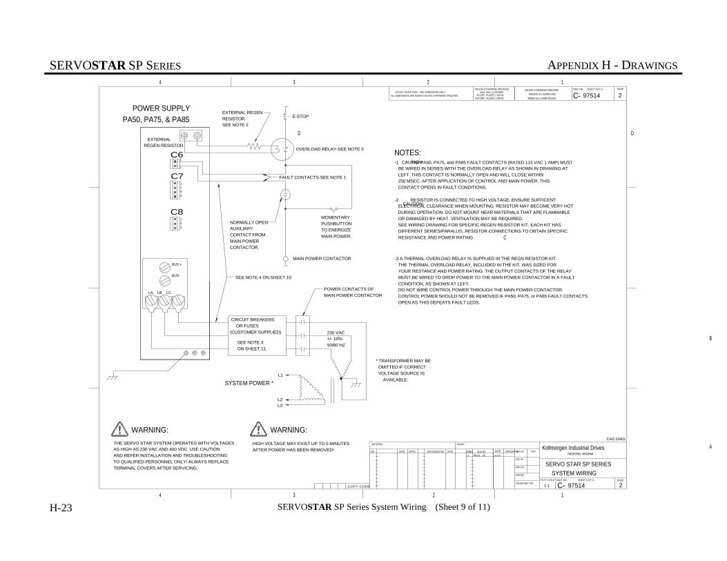
SERVOSTAR SP SERIES APPENDIX H - DRAWINGS
10-06-9789329 JDL 2
XXX DEC. PLACES ±.005 IN.XX DEC. PLACES ±.015 IN.
ANG. DIM. ±1 DEGREE DO NOT SCALE DWG. USE DIMENSIONS ONLY.
ALL DIMENSIONS ARE INCHES UNLESS OTHERWISE SPECIFIED.
UNLESS OTHERWISE SPECIFIED
CAD DWG
DWG. NO. SHEET 9 OF 11
DWG. NO. SHEET 9 OF 11
CH'K. BY:
DATE:
CROSS REF. NO:
JOB NO:
ECN NO.ISS. APP'D.APP'D.DATEDATE
FINISH:MATERIAL:
APP'D.DATE ECN NO.ECN NO. ISS.ISS.
4
4
3
3
2
2
1
1
DD
CC
BB
AA
UNLESS OTHERWISE SPECIFIED
REMOVE ALL BURRS AND
BREAK ALL SHARP EDGES.
ISSUE
DW'N. BY:
APP'D. BY:
PLOT SCALE ISSUE
C-
C-
97514 2
97514 21:1COPY CODE
SERVO STAR SP SERIES
SYSTEM WIRING
Kollmorgen Industrial DrivesRADFORD, VIRGINIA
BUS +
BUS-
C7
POWER SUPPLY
PA50, PA75, & PA85
WARNING:
THE SERVO STAR SYSTEM OPERATES WITH VOLTAGESAS HIGH AS 230 VAC AND 400 VDC. USE CAUTION
AND REFER INSTALLATION AND TROUBLESHOOTING
TO QUALIFIED PERSONNEL ONLY! ALWAYS REPLACE
TERMINAL COVERS AFTER SERVICING.
WARNING:
HIGH VOLTAGE MAY EXIST UP TO 5 MINUTES
AFTER POWER HAS BEEN REMOVED!
-1 THE PA50, PA75, and PA85 FAULT CONTACTS (RATED 115 VAC 1 AMP) MUST BE WIRED IN SERIES WITH THE OVERLOAD RELAY AS SHOWN IN DRAWING AT
LEFT. THIS CONTACT IS NORMALLY OPEN AND WILL CLOSE WITHIN
250 MSEC. AFTER APPLICATION OF CONTROL AND MAIN POWER. THIS
CONTACT OPENS IN FAULT CONDITIONS.
-2 RESISTOR IS CONNECTED TO HIGH VOLTAGE; ENSURE SUFFICENT ELECTRICAL CLEARANCE WHEN MOUNTING. RESISTOR MAY BECOME VERY HOT
DURING OPERATION. DO NOT MOUNT NEAR MATERIALS THAT ARE FLAMMABLE
OR DAMAGED BY HEAT. VENTILATION MAY BE REQUIRED.
SEE WIRING DRAWING FOR SPECIFIC REGEN RESISTOR KIT. EACH KIT HAS
DIFFERENT SERIES/PARALLEL RESISTOR CONNECTIONS TO OBTAIN SPECIFIC
RESISTANCE AND POWER RATING.
NOTES:
1
2
3
4
1
2
C6
C81
2
3
LA LB LC
EXTERNALREGEN RESISTOR
EXTERNAL REGEN
RESISTORSEE NOTE 2
MAIN POWER CONTACTOR
OVERLOAD RELAY-SEE NOTE 3
MOMENTARY
PUSHBUTTON
TO ENERGIZE
MAIN POWER.
E-STOP
CIRCUIT BREAKERS
OR FUSES
(CUSTOMER SUPPLIED)
CAUTION:
CAUTION:
-3 A THERMAL OVERLOAD RELAY IS SUPPLIED IN THE REGN RESISTOR KIT.
THE THERMAL OVERLOAD RELAY, INCLUDED IN THE KIT, WAS SIZED FOR
YOUR RESTANCE AND POWER RATING. THE OUTPUT CONTACTS OF THE RELAY
MUST BE WIRED TO DROP POWER TO THE MAIN POWER CONTACTOR IN A FAULT
CONDITION, AS SHOWN AT LEFT. DO NOT WIRE CONTROL POWER THROUGH THE MAIN POWER CONTACTOR.
CONTROL POWER SHOULD NOT BE REMOVED IF PA50, PA75, or PA85 FAULT CONTACTS
OPEN AS THIS DEFEATS FAULT LEDS.
POWER CONTACTS OF
MAIN POWER CONTACTOR
230 VAC+/- 10%
50/60 HZSEE NOTE 3
ON SHEET 11
* TRANSFORMER MAY BE
OMITTED IF CORRECT
VOLTAGE SOURCE IS
AVAILABLE.SYSTEM POWER *
L1
L2L3
NORMALLY OPENAUXILIARY
CONTACT FROM
MAIN POWER
CONTACTOR.
FAULT CONTACTS-SEE NOTE 1
SEE NOTE 4 ON SHEET 10
H-23 SERVOSTAR SP Series System Wiring (Sheet 9 of 11)

SERVOSTAR SP SERIES APPENDIX H - DRAWINGS
10-06-9789329 JDL 2
STATUS
LEDS
LA
N/C
LC
EARTH
LINE
INPUT
LOGIC
+15
-15
+8
EARTH GROUND
LOW INDUCTANCE
SEE INSTALLATION
INSTRUCTIONS IN TEXT
AC LOGIC POWER INNOT USED
AC LOGIC POWER IN
12
3
NOTESFUNCTIONPIN
LINE INPUT
CONNECTIONS1
2
3
LOGIC INPUT VOLTAGE
(SEE SPEC'S AND TEXT)
SEE NOTE 4 SHEET 10
LA
N/C
LC
1
2
34
LOGIC POWER
TO DRIVES
(SEE NOTE 1)
CAUTION:
NOTES:
-1 UP TO 2 DRIVES TOTAL MAY BE MOUNTED TO EITHER SIDE OF POWER SUPPLY (SEE MANUAL) (SEE NOTE 5, SHEET 10).
HIGH VOLTAGE MAY EXIST UP TO 5 MINUTESAFTER POWER HAS BEEN REMOVED!
WARNING:
THE SERVO STAR SYSTEM OPERATES WITH VOLTAGESAS HIGH AS 230 VAC AND 400 VDC. USE CAUTION
AND REFER INSTALLATION AND TROUBLESHOOTING
TO QUALIFIED PERSONNEL ONLY! ALWAYS REPLACE
TERMINAL COVERS AFTER SERVICING.
WARNING:
+15 VDC INPUT
-15 VDC INPUT
DC COMMON
+8 VDC INPUT
+15 VDC SUPPLY
-15 VDC SUPPLY
DC COMMON
+8 VDC SUPPLY
1
2
3
4
DRIVEPOWER SUPPLYPIN
C5
CONNECTIONS
1
23
4
LOGIC SUPPLY
PA-LM
C5
RADFORD, VIRGINIA
Kollmorgen Industrial Drives
SERVO STAR SP SERIES
SYSTEM WIRING
COPY CODE 1:1 297514
297514
C-
C-
ISSUEPLOT SCALE
APP'D. BY:
DW'N. BY:
ISSUE
BREAK ALL SHARP EDGES.
REMOVE ALL BURRS AND
UNLESS OTHERWISE SPECIFIED
AA
B B
C C
D D
1
1
2
2
3
3
4
4
ISS. ISS.ECN NO. ECN NO.DATE APP'D.
MATERIAL: FINISH:
DATE DATEAPP'D. APP'D.ISS. ECN NO.
JOB NO:
CROSS REF. NO:
DATE:
CH'K. BY:
DWG. NO. SHEET 10 OF 11
DWG. NO. SHEET 10 OF 11
CAD DWG
UNLESS OTHERWISE SPECIFIED DO NOT SCALE DWG. USE DIMENSIONS ONLY.
ALL DIMENSIONS ARE INCHES UNLESS OTHERWISE SPECIFIED.ANG. DIM. ±1 DEGREE
XX DEC. PLACES ±.015 IN.XXX DEC. PLACES ±.005 IN.
SEE NOTE 7A ON SHEET 10
H-24 SERVOSTAR SP Series System Wiring (Sheet 10 of 11)

SERVOSTAR SP SERIES APPENDIX H - DRAWINGS
10-02-9789329 JDL 2
SHEET 11 OF 11
SHEET 11 OF 11
1. WARNING: ALWAYS REPLACE TERMINAL COVERS AFTER SERVICE OR INSTALLATION!
RADFORD, VIRGINIA
Kollmorgen Industrial Drives
SERVO STAR SP SERIES
SYSTEM WIRING
COPY CODE 1:1 297514
297514
C-
C-
ISSUEPLOT SCALE
APP'D. BY:
DW'N. BY:
ISSUE
BREAK ALL SHARP EDGES.
REMOVE ALL BURRS AND
UNLESS OTHERWISE SPECIFIED
AA
B B
C C
D D
1
1
2
2
3
3
4
4
ISS. ISS.ECN NO. ECN NO.DATE APP'D.
MATERIAL: FINISH:
DATE DATEAPP'D. APP'D.ISS. ECN NO.
JOB NO:
CROSS REF. NO:
DATE:
CH'K. BY:
DWG. NO.
DWG. NO.
CAD DWG
UNLESS OTHERWISE SPECIFIED DO NOT SCALE DWG. USE DIMENSIONS ONLY.ALL DIMENSIONS ARE INCHES UNLESS OTHERWISE SPECIFIED.
ANG. DIM. ±1 DEGREEXX DEC. PLACES ±.015 IN.
XXX DEC. PLACES ±.005 IN.
7. RECOMMENDED TORQUES ARE A) CONTROL SIGNALS 2.25 IN-LB
B) SX03, SX06, SX10, SX20, PA08, PA14, AND PA28 MAX TORQUE 12 IN-LB: MOTOR, BUS CONNECTION AMD GROUND STUD C) SX30, SX55, PA50, PA75, AND PA85 MAX TORQUE 20 IN-LB: MOTOR, BUS CONNECTION AND GROUND STUD
6. THE SX03, SX06, SX10, SX20 AND PAO8 POWER TERMINAL BLOCKS INCORPORATE CAPTIVE SCREWS. DO NOT ATTEMPT TO REMOVE THEM FOR USE WITH RING TERMINALS. USE LOCKING SPRING SPADE TERMINALS SUCH AS HOLLINGSWORTH #XSS209545 OR #SS20947SF FOR 16/14 AWG WIRE AND #XSS20836 OR #XSS20832F FOR 12/10 AWG WIRE.
5. THE TOTAL NUMBER OF AXES ALLOWED PER POWER SUPPLY DEPENDS ON THE APPLICATION AND THE COMBINATION OF DRIVES REQUIRED POWER. PA-LM A MAXIMUM OF 2 DRIVES (SEE SPECIFICATIONS OF POWER SUPPLY AND REQUIREMENTS OF DRIVE) DO NOT EXCEED LOGIC SUPPLY CAPACITY!
PA08: A MAXIMUM OF 2 DRIVES (SEE SPECIFICATIONS OF POWER SUPPLY AND REQUIREMENTS OF DRIVE) DO NOT EXCEED LOGIC SUPPLY CAPACITY! PA14: A MAXIMUM OF 4 DRIVES (SEE SPECIFICATIONS OF POWER SUPPLY AND REQUIREMENTS OF DRIVE) DO NOT EXCEED LOGIC SUPPLY CAPACITY! PA28: A MAXIMUM OF 4 DRIVES (SEE SPECIFICATIONS OF POWER SUPPLY AND REQUIREMENTS OF DRIVE) DO NOT EXCEED LOGIC SUPPLY CAPACITY! PA50: A MAXIMUM OF 4 DRIVES (SEE SPECIFICATIONS OF POWER SUPPLY AND REQUIREMENTS OF DRIVE) DO NOT EXCEED LOGIC SUPPLY CAPACITY! PA75: A MAXIMUM OF 4 DRIVES (SEE SPECIFICATIONS OF POWER SUPPLY AND REQUIREMENTS OF DRIVE) DO NOT EXCEED LOGIC SUPPLY CAPACITY! PA85: A MAXIMUM OF 4 DRIVES (SEE SPECIFICATIONS OF POWER SUPPLY AND REQUIREMENTS OF DRIVE) DO N
4. ALL AC LINES SHOULD BE TWISTED CABLES.
RECOMMENDED RING TERMINALS8 AWG HOLLINGSWORTH R3027BF6 AWG HOLLINGSWORTH R4001BF4 AWG HOLINGSWORTH R5100BF
RECOMMENDED SPADE TERMINALS16/14 AWG HOLLINGSWORTH XSS20954S OR SS20947SF12/10 AWG HOLLINGSWORTH XSS20836 OR SS20832F
SX55, 6 AWG OR LARGER WIRE
SX30, 10 AWG OR LARGER WIRE
SX20, 10 AWG OR LARGER WIRE
SX10, 14 AWG OR LARGER WIRE
SX06, 14 AWG OR LARGER WIRE
SX03, 14 AWG OR LARGER WIRE
RECOMMENDED WIRE GUAGE DRIVES
PA85, 1 AWG OR LARGER WIRE
PA75, 4 AWG OR LARGER WIRE
PA50, 6 AWG OR LARGER WIRE
PA28, 10 AWG OR LARGER WIRE
PA14, 14 AWG OR LARGER WIRE
PA08, 14 AWG OR LARGER WIRE
RECOMMENDED WIRE GUAGE POWER SUPPLIES
THE POWER BUS BETWEEN POWER SUPPLIES (PA08, PA14, PA28, PA50, PA75, AND PA85) AND DRIVES SHOULD USE THEFOLLOWING MINIMUM WIREGUAGE WITH 600 VAC INSULATION. USE ONLY COPPER WIRE. WIRE SIZE MAY BE DETERMINEDFROM TABLE 310-16 OF THE NEC 60° OR 75° COLUMN.
THE ACTUAL APPLICATION MAY REQUIRE LESS CURRENT, USE 600V VAC INSULATED WIRE AND REFER TO LOCALELECTRICAL CODES FOR PROPERWIRE SIZE FOR THE CURRENTS LISTED ABOVE. FUSES FOR MAIN POWER SHOULD BE AUL RATEDTIME DELAY TYPE, SUCH AS, BUSS FRN-RSERIES. CONTROLS CIRCUITS SHALL BE PROVIDED WITHAPPROPRIATEOVER-CURRENT PROTECTION.
PA85 HAS A MAXIMUM MAIN POWER INPUT CURRENT OF 85 AMPS RMS. FUSE FOR 100 AMPS (FRN-100 OR EQUIVALENT).
PA75 HAS A MAXIMUM MAIN POWER INPUT CURRENT OF 75 AMPS RMS. FUSE FOR 80 AMPS (FRN-80 OR EQUIVALENT).
PA50 HAS A MAXIMUM MAIN POWER INPUT CURRENT OF 50 AMPS RMS. FUSE FOR 60 AMPS (FRN-60 OR EQUIVALENT).
PA28 HAS A MAXIMUM MAIN POWER INPUT CURRENT OF 28 AMPS RMS. FUSE FOR 35 AMPS (FRN-35 OR EQUIVALENT).
PA14 HAS A MAXIMUM MAIN POWER INPUT CURRENT OF 14 AMPS RMS. FUSE FOR 20 AMPS (FRN-20 OR EQUIVALENT).
PA08 HAS A MAXIMUM MAIN POWER INPUT CURRENT OF 8 AMPS RMS. FUSE FOR 10 AMPS (FRN-10 OR EQUIVALENT).
3. WIRE SIZES, BREAKERS AND FUSES FOR SERVOSTAR.
2. DRIVE AND POWER SUPPLY MUST BE INSTALLED IN AN ENCLOSURE (VENTILATION OR COOLING MAY BE NECESSARY TO PREVENT ENCLOSURE AMBIENT FROM EXCEEDING 45°C).
8. ALL SIGNAL AND CONTROL WIRES TO BE 22-18 AWG. THE CRIMP TERMINALS ARE SUPPLIED IN THE CONNECTOR KITS. IF 16 AWG WIRE IS USED, ORDER MOLEX TERMINALS #39-00-0078. SHIELDED CABLES RECOMMENDED. REFER
TO MANUAL FOR SIGNAL DESCRIPTIONS AND REQUIREMENTS.
9. SHIELDING OF SIGNAL CABLES OFTEN PROVIDES BEST PERFORMANCE WHEN SHIELDS ARE TIED ONLY AT SOURCE END.
10. REFER TO MANUAL FOR SIGNAL SPECIFICATIONS.
11. COMMUTATION SIGNAL FROM ENCODER'S COMMUTATION TRACKS OR HALL EFFECT SENSORS. MAY BE DRIVEN DIFFENENTIALLY AS SHOWN, OR SINGLE ENDED INPUTS ON HX AND HX CONNECTED TO SENSOR'S +5VDC SUPPLY.
12. OPERATION MODES 2 AND 3 REQUIRE COMPENSATION COMPONENTS INSTALLED IN HEADER LOCATION "COMP". SEE MANUAL FOR DETAILS.
H-25 SERVOSTAR SP Series System Wiring (Sheet 11 of 11)

SERVOSTAR SP SERIES APPENDIX H - DRAWINGS
H-26

SERVOSTAR SP SERIES GLOSSARY
Glossary-1
GLOSSARY
Acceleration
The change in velocity as a function of time.Acceleration usually refers to increasing velocity anddeceleration describes decreasing velocity.
Ambient Temperature
The temperature of the cooling medium, usually air,immediately surrounding the motor or another device.
Amplifier
Electronics which convert low level command signalsto high power voltages and currents to operate a servomotor.
Brushless Servo Drive
A servo drive used to control a permanent magnetsynchronous AC motor. May also be referred to as anAC Servo Drive.
Drive
This is the electronics portion of the system thatcontrols power to the motor.
Drive, Analog
Usually referring to any type of motor drive in whichthe input is an analog signal.
Drive, Servo
A motor drive which utilizes internal feedback loopsfor accurate control of motor current and/or velocity.
Efficiency
The ratio of output power to input power.
Encoder, Absolute
A digital position transducer in which the output isrepresentative of the absolute position of the inputshaft within one (or more) revolutions. Output isusually a parallel digital word.
Encoder, Incremental
A position encoding device in which the outputrepresents incremental changes in position.
Encoder, Marker
A once-per-revolution signal provided by someincremental encoders to specify a reference pointwithin that revolution. Also known as ZeroReference signal or index pulse.
Encoder Resolution
A measure of the smallest positional change whichcan be detected by the encoder.
Feedback
A signal which is transferred from the output back tothe input for use in a closed loop system.
Following Error
The position error during motion resulting from useof a position control loop with proportional gain only.
Friction
A resistance to motion caused by surfaces rubbingtogether. Friction can be constant with varying speed(coulomb friction) or proportional to speed (viscousfriction) or present at rest (static friction).
Full Load Current
The armature current of a motor operated at its fullload torque and speed with rated voltage applied.
Full Load Speed
The speed of a motor operated with rated voltage andfull load torque.
Gain
The ratio of system output signal to system inputsignal. The control loop parameter that determinessystem performance characteristics.
HP: Horsepower
One horsepower is equal to 746 watts. SincePower = Torque × Speed, horsepower is a measure ofa motor's torque and speed capability (e.g. a 1 HPmotor will produce 35 lb-in. at 1800 rpm).

GLOSSARY SERVOSTAR SP SERIES
Glossary-2
I/O: Input/Output
The reception and transmission of informationbetween control devices. In modern control systems,I/O has two distinct forms: switches, relays, etc.,which are in either an on or off state, or analogsignals that are continuous in nature such as speed,temperature, flow, etc.
Inertia
The property of an object to resist changes in velocityunless acted upon by an outside force. Higher inertiaobjects require larger torques to accelerate anddecelerate. Inertia is dependent upon the mass andshape of the object.
Inertial Match
An inertial match between motor and load is obtainedby selecting the coupling ratio such that the loadmoment of inertia referred to the motor shaft is equalto the motor moment of inertia.
Inrush Current
The current surge generated when a piece ofequipment such as a servo amplifier is connected toan AC line. This surge is typically due to the impulsecharging of a large capacitor located in theequipment.
Instability
Undesirable motion of an actuator that is differentfrom the command motion. Instability can take theform of irregular speed or hunting of the final restposition.
Limits
Motion control systems may have sensors calledlimits that alert the control electronics that thephysical end of travel is being approached and thatmotion should stop.
Logic Ground
An electrical potential to which all control signals in aparticular system are referenced.
Loop, Feedback Control
A control method that compares the input from ameasurement device, such as an encoder ortachometer, to a desired parameter, such as a positionor velocity and causes action to correct any detected
error. Several types of loops can be used incombination (i.e. velocity and position together) forhigh performance requirements.
Master Slave Motion Control
A type of coordinated motion control where themaster axis position is used to generate one or moreslave axis position commands.
Motor, AC
A device that converts electrical alternating currentinto mechanical energy. Requires no commutationdevices such as brushes. Normally operated offcommercial AC power. Can be single or multiplephase.
Oscillation
An effect that varies periodically between two values.
PLC
Programmable Logic Controller. Also known as aprogrammable controller, these devices are used formachine control and sequencing.
Power
The rate at which work is done. In motion control,Power = Torque × Speed.
Pulse Rate
The frequency of the step pulses applied to a step-permotor driver. The pulse rate divided by theresolution of the motor/drive combination ( in stepsper revolution) yields the rotational speed inrevolutions per second.
Ramping
The acceleration and deceleration of a motor. Mayalso refer to the change in frequency of the appliedstep pulse train.
Rated Torque
The torque producing capacity of a motor at a givenspeed. This is the maximum continuous torque themotor can deliver to a load and is usually specifiedwith a torque/speed curve.
SERVOSTAR SP SERIES GLOSSARY
Glossary-3
Regeneration
The action during motor braking, in which the motoracts as a generator and takes kinetic energy from theload, converts it to electrical energy, and returns it tothe amplifier.
Repeatablity
The degree to which the positioning accuracy for agiven move performed repetitively can be duplicated.
Resolution
The smallest positioning increment that can beachieved. Frequently defined as the number of stepsor feedback units required for a motor's shaft to rotateone complete revolution.
Resolver
A position transducer utilizing magnetic coupling tomeasure absolute shaft position over one revolution.
RMS Current
Root mean square current. In an intermittent dutycycle application, the RMS current is equal to thevalue of steady state current which would produce theequivalent resistive heating over a long period oftime.
Rotor
The rotating part of a magnetic structure. In a motor,the rotor is connected to the motor shaft.
Servo Amplifier/Servo Drive
An electronic device which produces the windingcurrent for a servo motor. The amplifier converts alow level control signal into high voltage and currentlevels top produce torque in the motor.
Servo System
An automatic feedback control system for mechanicalmotion in which the controlled or output quantity isposition, velocity, or acceleration. Servo systems areclosed loop systems.
Shunt Resistor
A device located in a servo amplifier for controllingregenerative energy generated when braking a motor.This device dissipates of "dumps" the kinetic energyas heat.
Single Point Ground
The common connection point for signal grounds in acontrol wiring environment.
Slew
In motion control the portion of a move made at aconstant non-zero velocity.
Speed Regulation
For a speed control system, speed regulation is thevariation in actual speed expressed as a percentage ofset speed.
Stiffness
Ratio of an applied force torque to change in positionfor a mechanical system.
Stator
The non-rotating part of a magnetic structure. In amotor the stator usually contains the mountingsurface, bearings, and non-rotating windings orpermanent magnets.
Tachometer
An electromagnetic feedback transducer whichproduces an analog voltage signal proportional torotational velocity. Tachometers can be either brushor brushless.
Torque
The rotary equivalent to force. Equal to the productof the force perpendicular to the radius of motion anddistance from the center of rotation to the point wherethe force is applied.
Velocity
The change in position as a function of time.Velocity has both a magnitude and direction.

GLOSSARY SERVOSTAR SP SERIES
Glossary-4

SERVOSTAR SP SERIES INDEX
i
INDEX
- A -
Abbreviations............................................................................................................................................. 2-2Analog Input Signals.................................................................................................................................. 1-5Assembly.................................................................................................................................................... 2-3 Mounting........................................................................................................................................... 2-3 Mounting the External Regeneration Resistor(s) .............................................................................. 2-4
- B -
Brushless DC Motor .................................................................................................................................. 1-3
- C -
Checking the AC Line Voltages................................................................................................................. 2-13Checking the DC Bus Voltages.................................................................................................................. 2-13Checking the Motor Wiring ....................................................................................................................... 2-13Connecting the AC Input Voltage .............................................................................................................. 2-6Connecting the External Regeneration Resistor(s)..................................................................................... 2-7Connecting the Main DC Bus Voltage....................................................................................................... 2-6Connecting the Motor ................................................................................................................................ 2-12Connecting the SERVOSTAR SP Series Drive Analog Input / Output (Connector C2) ........................... 2-8Connecting the SERVOSTAR SP Series Drive Digital Input / Output (Connector C3)............................ 2-9Connecting the SERVOSTAR SP2 Series Drive Digital Input / Output (Connector C1).......................... 2-11Connecting the Unregulated DC Voltage to the SERVOSTAR SP Series Drive (Connector C5) ............ 2-7Conventions ............................................................................................................................................... 2-2 Abbreviations.................................................................................................................................... 2-2 Model Numbering Scheme ............................................................................................................... 2-2Current Feedback Signals .......................................................................................................................... 1-4Current Ratings and Duty Cycles ............................................................................................................... 1-5
- D -
- E -
Electrical Connections ............................................................................................................................... 2-4 Connecting the AC Input Voltage ..................................................................................................... 2-6 Connecting the External Regeneration Resistor(s)............................................................................ 2-7 Connecting the Main DC Bus Voltage.............................................................................................. 2-6 Connecting the Motor ....................................................................................................................... 2-12 Connecting the SERVOSTAR SP Series Drive Analog Input / Output (Connector C2) .................. 2-8 Connecting the SERVOSTAR SP Series Drive Digital Input / Output (Connector C3)................... 2-9 Connecting the SERVOSTAR SP2 Series Drive Digital Input / Output (Connector C1)................. 2-11 Connecting the Unregulated DC Voltage to the SERVOSTAR SP Series Drive (Connector C5) ... 2-7 Grounding Scheme............................................................................................................................ 2-6 Recommended Torque for Electrical Connections............................................................................ 2-5Electrical Noise.......................................................................................................................................... 4-2Enclosures.................................................................................................................................................. 2-3Environmental Requirements ..................................................................................................................... 2-3
INDEX SERVOSTAR SP SERIES
ii
- F -
Features ......................................................................................................................................................1-1Field Serviceability ....................................................................................................................................5-1
- G -
Grounding Integrity....................................................................................................................................4-3Grounding Scheme.....................................................................................................................................2-6
- H -
- I -
Initial Start-up ............................................................................................................................................3-1Installation Checklist..................................................................................................................................2-13 Checking the AC Line Voltages ........................................................................................................2-13 Checking the DC Bus Voltages .........................................................................................................2-13 Checking the Motor Wiring ..............................................................................................................2-13Installation Requirements...........................................................................................................................2-3 Enclosures .........................................................................................................................................2-3 Environmental Requirements ............................................................................................................2-3
- J -
- K -
- L -
- M -
Model Numbering Scheme.........................................................................................................................2-2Mounting....................................................................................................................................................2-3Mounting the External Regeneration Resistor(s)........................................................................................2-4
- N -
- O -
- P -
Periodic Maintenance.................................................................................................................................4-3 Grounding Integrity...........................................................................................................................4-3 Ventilation.........................................................................................................................................4-3Power Supply Amp Status LED's ...............................................................................................................5-3Power Supply Module................................................................................................................................1-2Power Up/Down Sequencing .....................................................................................................................1-3

SERVOSTAR SP SERIES INDEX
iii
- P - (continued)
Preventative Maintenance .......................................................................................................................... 4-1 Electrical Noise................................................................................................................................. 4-2 Radio Frequency Energy` ................................................................................................................. 4-2 Surge Current .................................................................................................................................... 4-2 Transient Voltages ............................................................................................................................ 4-1PWM Input Command Signals .................................................................................................................. 1-4
- Q -
- R -
Radio Frequency Energy` .......................................................................................................................... 4-2Recommended Torque for Electrical Connections..................................................................................... 2-5
- S -
Safety Information ..................................................................................................................................... 2-1Sequence of Operations ............................................................................................................................. 3-1SERVOSTAR SP Drive Module ............................................................................................................... 1-2SERVOSTAR SP Series Drive or Power Supply Reset Procedures.......................................................... 5-3SERVOSTAR SP Series Drive Status LED's ............................................................................................ 5-2Signal Information ..................................................................................................................................... 1-4 Analog Input Signals......................................................................................................................... 1-5 Current Feedback Signals ................................................................................................................. 1-4 PWM Input Command Signals ......................................................................................................... 1-4 Six-step Commutation....................................................................................................................... 1-5Six-step Commutation................................................................................................................................ 1-5Surge Current ............................................................................................................................................. 4-2Symptoms and Corrections ........................................................................................................................ 5-2 Power Supply Amp Status LED's...................................................................................................... 5-3 SERVOSTAR SP Series Drive or Power Supply Reset Procedures................................................. 5-3 SERVOSTAR SP Series Drive Status LED's ................................................................................... 5-2 The Motor Exhibits Very Low Torque or is Totally Inoperative ...................................................... 5-2 The Motor is Erratic or Exhibits an Improper Mode of Operation ................................................... 5-2
- T -
The Motor Exhibits Very Low Torque or is Totally Inoperative ............................................................... 5-2The Motor is Erratic or Exhibits an Improper Mode of Operation ............................................................ 5-2Theory of Operation................................................................................................................................... 1-2 Brushless DC Motor ......................................................................................................................... 1-3 Power Supply Module....................................................................................................................... 1-2 Power Up/Down Sequencing ............................................................................................................ 1-3 SERVOSTAR SP Drive Module ...................................................................................................... 1-2Transient Voltages ..................................................................................................................................... 4-1Typical System Diagram............................................................................................................................ 1-4
- U -

INDEX SERVOSTAR SP SERIES
iv
Unpacking and Inspection ..........................................................................................................................2-2
- V -
Ventilation..................................................................................................................................................4-3
- W -
- X -
- Y -
- Z -
