southern california edison’s presidential substation ... · presidential substation project i esa...
TRANSCRIPT

Volume 2: Appendices
SOUTHERN CALIFORNIA EDISON’S PRESIDENTIAL SUBSTATION PROJECT CPUC A.08-12-023 SCH #: 2009021059
Final Environmental Impact Report (Response to Comments)
Prepared for: March 2013California Public Utilities Commission

Volume 2: Appendices
SOUTHERN CALIFORNIA EDISON’S PRESIDENTIAL SUBSTATION PROJECT CPUC A.08-12-023 SCH #: 2009021059
Final Environmental Impact Report (Response to Comments)
Prepared for: March 2013California Public Utilities Commission 505 Van Ness Avenue San Francisco, CA 94102
550 Kearny Street Suite 800 San Francisco, CA 94104 415.896.0000 www.esassoc.com
Los Angeles
Oakland
Olympia
Petaluma
Portland
Sacramento
San Diego
Seattle
Tampa
Woodland Hills
207584.02

Presidential Substation Project i ESA / 207584.02
(A.08-12-023) Final Environmental Impact Report March 2013
TABLE OF CONTENTS Southern California Edison’s Presidential Substation Project (A.08-12-023) Final Environmental Impact Report (Response to Comments)
Page
Volume 1 (bound separately)
1. Introduction
2. Public Review Process
3. Comments and Responses
4. Revisions to the Draft EIR
Volume 2
Appendices
A. Notice of Availability A-1 B. Draft EIR Newspaper Legal Advertisements B-1 C. Public Meeting Sign-in Sheets C-1 D. Public Meeting Presentation D-1 E. Form Letters Received E-1 F. Mailing List F-1 G. Certificate of Service G-1 H. Data Responses 7, 8, 9, and 10 Non-Confidential H-1 I. Construction Noise I-1 J. Mitigation Monitoring, Reporting, and Compliance Program J-1

Presidential Substation Project A-1 ESA / 207584.02
(A.08-12-023) Final Environmental Impact Report March 2013
APPENDIX A Notice of Availability

This page intentionally left blank
A-2

STATE OF CALIFORNIA JERRY BROWN, Governor
PUBLIC UTILITIES COMMISSION 505 VAN NESS AVENUE SAN FRANCISCO, CA 94102-3298
To: State Clearinghouse, Responsible and Trustee Agencies, Property Owners& Interested Parties
From: Juralynne Mosley, Environmental Project Manager
Subject: NOTICE OF AVAILABILITY OF A DRAFT ENVIRONMENTAL IMPACT REPORT (DRAFT EIR) AND PUBLIC MEETING: Presidential Substation Project (A.08-12-023) SCH No. 2009021059
Date: September 16, 2011
The California Public Utilities Commission (CPUC) has prepared a Draft Environmental Impact Report (Draft EIR) under the California Environmental Quality Act (CEQA) for consideration of Southern California Edison’s (SCE) application to construct, operate and maintain the Presidential Substation Project (A.08-12-023). The Draft EIR details the Proposed Project, evaluates and describes the potential environmental impacts associated with the construction, operation and maintenance of the Proposed Project, identifies those impacts that could be significant, and presents mitigation measures which, if adopted by the CPUC or other responsible agencies, could avoid or minimize these impacts. The Draft EIR also evaluates alternatives to the Proposed Project, including the No Project Alternative, as required by CEQA.
Description of the Proposed Project.The Proposed Project is located in the City of Thousand Oaks and unincorporated Ventura County. SCE requests authorization to:
� Construction of a new 66/16 kV distribution substation (proposed Presidential Substation) on an approximately 4-acre site;
� Replacement of existing 16 kV distribution and subtransmission poles with new subtransmission poles and installation of 66 kV subtransmission conductor to supply the proposed Presidential Substation;
� Installation of underground 66 kV subtransmission facilities for the portion of the route crossing Highway 23 (Hwy 23);
� Construction or relocation of related 16 kV distribution components, including four new 16 kV distribution getaways at the proposed Presidential Substation, and relocation, transfer, or upgrade of existing 16 kV distribution facilities either to new subtransmission poles or to new underground 16 kV distribution facilities. Upgrades to new 16 kV distribution would involve installation of new conductors instead of re-hanging or burying the existing 16 kV conductor; and
� Construction of facilities to connect the proposed Presidential Substation to SCE’s existing telecommunications system.
The objectives of the Proposed Project are to meet long term electrical demand requirements and improve electrical system operational flexibility and reliability in a cost effective manner.
A-3

- 2 -
Public Comment on the Draft EIR. The Draft EIR is available for a 45-day public comment period September 16, 2011 through Oct 31, 2011. The public may present comments and concerns regarding the Proposed Project and the adequacy of the Draft EIR. Written comments on the Draft EIR must be postmarked or received by fax or e-mail no later than October 31,2011. Please be sure to include your name, address, and telephone number in your correspondence.
Written comments on the Draft EIR should be sent to: Ms. Juralynne Mosley
Presidential Substation Project c/o ESA
1425 N. McDowell Blvd., Suite 200 Petaluma, CA 94954
Phone: (415) 962-8409 Fax: (415) 896-0332
The CPUC will also hold a public comment meeting to receive oral and written comments from interested parties. Following the end of the public comment period, responses to all comments received on the Draft EIR and submitted within the specified 45-day review period will be prepared by the CPUC and included in a response to comments document, which together with the Draft EIR, will constitute the Final EIR for the Proposed Project. The public meeting will be held:
Thursday October 13, 2011 6:30 pm – 8:30 pm
Palm Garden Hotel, 495 N. Ventu Park Road, Thousand Oaks, CA 91320
Availability of Draft EIR.Copies of the Draft EIR will be available for public review at the Moorpark City Library, Grant R. Brimhall Library in Thousand Oaks, Simi Valley Library, and on the project website: http://www.cpuc.ca.gov/Environment/info/esa/presidentialsubstation/index.html. This website will be used to post all public documents during the environmental review process and to announce any upcoming public meetings. Hard copies or CD copies of the Draft EIR may be requested by telephone at (415) 962-8409 or by e-mail at [email protected].
Project information repositories include the following branches:
Moorpark City Library 699 Moorpark Ave
Moorpark, CA 93021 Phone: (805) 517-6370
Grant R. Brimhall Library 1401 E. Janss Road
Thousand Oaks, CA 91362Phone : (805) 449-2660
Simi Valley Library 2969 Tapo Canyon
Simi Valley, CA 93063 Phone : (805) 526-1735
REMINDER: Draft EIR comments will be accepted by fax, e-mail, or postmark through October 31, 2011. Please be sure to include your name, address, and telephone number.
A-4

#*#*
Bard Reservoir
Overland Alignment
Underground atHWY 23 Crossing
Ove
rland
Alig
nm
ent
UV23
UV118
UV23
UV118
Arroyo Simi
Arroyo Santa Rosa
MOORPARK-ROYAL NO. 2
MO
OR
PAR
K-T
HO
US
AN
D O
AK
S N
O. 2
Presidential Substation Project . 207584.02Figure ES-2
Alternative Subtransmission AlignmentsSOURCE: SCE, 2010
M o o r p a r kM o o r p a r k
Sunset Hills Blvd.
E. Olsen Rd
Madera Rd
Tierra Rejada Rd
Sunset Valley Rd.
Read Rd
Proposed SubtransmissionAlignment
Proposed 16 kV DistributionLine (underground)
#* Proposed PresidentialSubstation
Alignment 1 (overhead)
Alignment 2 (overhead)
Alignment 3 (overhead)
Alignment 3 (underground)
#* Alternative Substation Site B
Existing SCE 66 kVSubtransmission Line
Mad
era
Rd
N M
ader
a R
d
Espera nce Rd
T h o u s a n dT h o u s a n dO a k sO a k s
S i m i V a l l e yS i m i V a l l e y
* Alignments would serve the proposed or alternative substation
* Alignments would be adjacent to existing roads unless indicated as "overland route"
0 1
Miles
A-5

Presidential Substation Project B-1 ESA / 207584.02
(A.08-12-023) Final Environmental Impact Report March 2013
APPENDIX B Draft EIR Newspaper Legal Advertisements

This page intentionally left blank
B-2

Client:
ESA ENERGY GROUP
Account # 164487 Ad # 288188
Phone: (415) 896-5900
Fax: (415) 962-8490
Address: 225 BUSH ST., 170
SAN FRANCISCO, CA 94104
Sales Rep.:
Phone: (805) 437-0352
Fax: (805) 437-0065
Email: [email protected]
Entry date: 09/14/2011 03:18 PM
Class.: 1299 Other Public Notices
Requested By:
NISHA CHAUHAN
PO #: D207584.02
Entered By: 147412
Printed By: 147412
Start Date: 09/19/2011
End Date: 09/19/2011
Nb. of 2
Publications: Ventura County Star
Web
Total Price: $143.00
Paid Amount: $0.00
Page 1 of 1
California Public Utilities CommissionPublic Notification for Release of a DraftEnvironmental Impact Report and Public
Comment Meeting for the PresidentialSubstation Project
Notice is hereby given that the California Public Utilities Commission (CPUC) has released a Notice of Availability for the Draft Environmental Impact Report (DEIR) for the Presidential Substation Project (Proposed Project), for public review and comment. The DEIR addresses site- specific impacts of the construction, operation, and main- tenance of the Proposed Project, and alternatives. Infor- mation to be included in the EIR may also be based on input and comments received during the 45-day com- ment period that is open from September 16, 2011 until 5:00 p.m. on October 31, 2011. The Draft EIR is available for public review on the project website at:http://www.cpuc.ca.gov/Environment/info/esa/presiden- tialsubstation/index.htmlThe website includes further information on the environ- mental review process for this project and will be updat- ed during the review process. Public comments may be submitted in writing to: Ms. Juralynne Mosley, Presiden- tial Substation Project, c/o ESA, 1425 N. McDowell Blvd., Suite 200, Petaluma, CA 94954; by fax to (415) 896-0332; or by email to presidentialsub@esas- soc.com.
Additionally, the CPUC will hold a Public Meeting on Thursday, October 13, 2011 at Palm Garden Hotel, 495 North Ventu Park Road, Thousand Oaks, California 91320. The public meeting will convene from 6:30 p.m.- 8:30 p.m. All members of the public are invited to attend the meeting to comment on the Draft EIR.Publish: Sept. 19, 2011 Ad No.288188
B-3

Client:
ESA ENERGY GROUP
Account # 164487 Ad # 288188
Phone: (415) 896-5900
Fax: (415) 962-8490
Address: 225 BUSH ST., 170
SAN FRANCISCO, CA 94104
Sales Rep.:
Phone: (805) 437-0352
Fax: (805) 437-0065
Email: [email protected]
Entry date: 09/14/2011 03:54 PM
Class.: 1299 Other Public Notices
Requested By:
NISHA CHAUHAN
PO #: D207584.02
Entered By: 147412
Printed By: 147412
Start Date: 09/19/2011
End Date: 09/24/2011
Nb. of 4
Publications: Ventura County Star
Web
Total Price: $286.00
Paid Amount: $0.00
Page 1 of 1
California Public Utilities CommissionPublic Notification for Release of a DraftEnvironmental Impact Report and Public
Comment Meeting for the PresidentialSubstation Project
Notice is hereby given that the California Public Utilities Commission (CPUC) has released a Notice of Availability for the Draft Environmental Impact Report (DEIR) for the Presidential Substation Project (Proposed Project), for public review and comment. The DEIR addresses site- specific impacts of the construction, operation, and main- tenance of the Proposed Project, and alternatives. Infor- mation to be included in the EIR may also be based on input and comments received during the 45-day com- ment period that is open from September 16, 2011 until 5:00 p.m. on October 31, 2011. The Draft EIR is available for public review on the project website at:http://www.cpuc.ca.gov/Environment/info/esa/presiden- tialsubstation/index.htmlThe website includes further information on the environ- mental review process for this project and will be updat- ed during the review process. Public comments may be submitted in writing to: Ms. Juralynne Mosley, Presiden- tial Substation Project, c/o ESA, 1425 N. McDowell Blvd., Suite 200, Petaluma, CA 94954; by fax to (415) 896-0332; or by email to presidentialsub@esas- soc.com.
Additionally, the CPUC will hold a Public Meeting on Thursday, October 13, 2011 at Palm Garden Hotel, 495 North Ventu Park Road, Thousand Oaks, California 91320. The public meeting will convene from 6:30 p.m.- 8:30 p.m. All members of the public are invited to attend the meeting to comment on the Draft EIR.Publish: Sept. 19, 24, 2011 Ad No.288188
B-4

Presidential Substation Project C-1 ESA / 207584.02
(A.08-12-023) Final Environmental Impact Report March 2013
APPENDIX C Public Meeting Sign-in Sheets

This page intentionally left blank
C-2

C-3

C-4

C-5

C-6

C-7


Presidential Substation Project D-1 ESA / 207584.02
(A.08-12-023) Final Environmental Impact Report March 2013
APPENDIX D Public Meeting Presentation

This page intentionally left blank
D-2

Presidential SubstationProject
California Public Utilities Commission bli iPublic Comment Meeting
on theDraft Environmental Impact Report (DEIR)
October 13, 2011Thousand Oaks CA
1
Thousand Oaks, CA
D-3

P rti ip t d th ir R lParticipants and their Roles
L M l CPUC P j t M� Lynne Mosley, CPUC Project Manager� Lead Agency under the California Environmental Quality
Act (CEQA)
� Mike Manka, ESA Project Manager � Environmental Consultant for the CPUC
� Southern California Edison� Project Applicant
� Public Agencies
� Members of the Public
2
D-4

M ti A dMeeting Agenda
CPUC Review and CEQA Process� CPUC Review and CEQA Process� Project Overview
Alt ti� Alternatives� Summary of Environmental Impacts� Next Steps� Public Comment
� Speaker cards� Comment forms
3
D-5

CPUC d CEQA R i PCPUC and CEQA Review Process
4
D-6

Wh D th CPUC R l t ?Who Does the CPUC Regulate?Electricity
CPUC
ElectricityTelephone
Communication
N t l GCPUC Natural Gas
WaterTransportationTransportation
and Rail
Purpose:Purpose:To ensure that utility services are
provided to the public in a safe and reliable manner and at areliable manner and at a
reasonable price
D-7
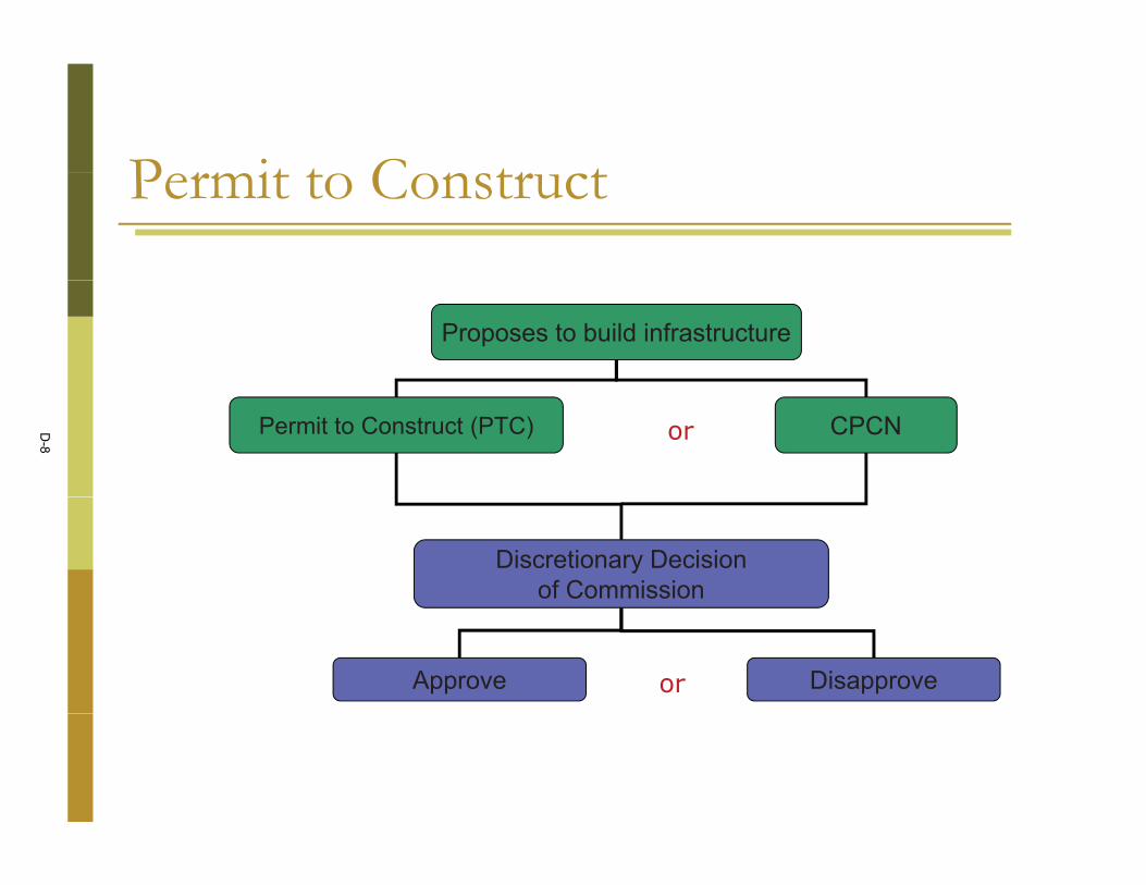
P r it t C tr tPermit to Construct
Proposes to build infrastructure
Permit to Construct (PTC) CPCNor
Discretionary Decisionof Commission
Approve Disapproveor
D-8

CPUC R i PrCPUC Review Process
Economic Review
Market Meet NeedsMarketRates MarketCompetition
Meet Needsof People
MarketStructure
Environmental Review Complies with CEQA
Public Awareness toEnvironmental Impacts
MitigationMeasures Alternatives
D-9
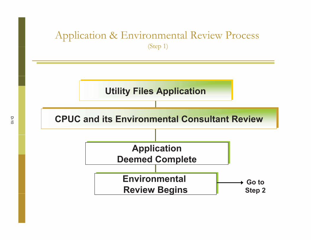
Application & Environmental Review Process (Step 1)(Step 1)
Utility Files Application
CPUC and its Environmental Consultant Review
ApplicationDeemed Completep
EnvironmentalReview Begins
Go toStep 2g p
D-10

Application & Environmental Review Process pp(Step 2)
Environmental Review Begins
EnvironmentalReview in Field
AgencyConsultation
ConductI iti l St dInitial Study
PrepareMiti t d N ti
PrepareE i t l Go toMitigated Negative
DeclarationEnvironmentalImpact Report
or Go toStep 3
D-11

Application & Environmental Review Processpp(Step 3)
PPrepareDraft EIR
Contains“Environmentally
Superior” Route and Other Alternatives
ScopingMeetings
Public NoticeReceive information
from public to
Other Alternatives
Public Noticeof Draft EIR
determine the range of issues and alternatives
Public Comments
Final EIR
D-12

Application & Environmental Review Processpp(Step 4)
Fi l EIRFinal EIR
ALJ Proposes Decision for Contains Routing, EconomicIssues Social Impactp
Commission Issues, Social ImpactIssues, And Need for Project
ALJ’s Proposed Decision
Interveners Comment on Proposed Decision
Proposed Final Decision
Commissioners Vote
D-13

Pr j t O r iProject Overview
12
D-14

Pr p d Pr j t L tiProposed Project Location� Insert Figure ES-1 Proposed Project Overview
13
D-15

Pr j t D riptiProject Description� The Proposed Project is located in the City of Thousand Oaks and
unincorporated Ventura County SCE requests authorization to:unincorporated Ventura County. SCE requests authorization to:
� Construction of a new 66/16 kV distribution substation (proposed Presidential Substation) on an approximately 4-acre site;
R l t f i ti 16 kV di t ib ti d bt i i l ith� Replacement of existing 16 kV distribution and subtransmission poles with newsubtransmission poles and installation of 66 kV subtransmission conductor to supply the proposed Presidential Substation;
� Installation of underground 66 kV subtransmission facilities for the portion of g pthe route crossing Highway 23 (Hwy 23);
� Construction or relocation of related 16 kV distribution components, including four new 16 kV distribution getaways at the proposed Presidential Substation, and relocation transfer or upgrade of existing 16 kV distribution facilities eitherand relocation, transfer, or upgrade of existing 16 kV distribution facilities either to new subtransmission poles or to new underground 16 kV distribution facilities. Upgrades to new 16 kV distribution would involve installation of new conductors instead of re-hanging or burying the existing 16 kV conductor; and
� Construction of facilities to connect the proposed Presidential Substation to
14
� Construction of facilities to connect the proposed Presidential Substation to SCE’s existing telecommunications system.
D-16

Project Objectivesj jSCE Objectives:
� Meet long term electrical demand requirements in the ENA beginning in fall of 2012 orwinter of 2013 and extending beyond 2014 in order to meet the 10-year planning criterion;
� Improve electrical system operational flexibility and reliability by providing the ability totransfer load between 16 kV distribution circuits and distribution substations within the ENA;transfer load between 16 kV distribution circuits and distribution substations within the ENA;
� Meet project needs while minimizing environmental impacts; and
� Meet project needs in a cost-effective manner.
According to SCE, construction of the Proposed Project is needed to maintain safe and reliableelectric service to customers and to serve forecasted electrical demand in the ENA.
CEQA Team Objectives:
M t l t l t i l d d i t i th ENA d fi d i th t� Meet long term electrical demand requirements in the ENA as defined in the proponentsapplication and PEA (SCE 2008); and
� Improve electrical system operational flexibility and reliability by providing the ability totransfer load between 16 kV distribution circuits and 16k V distribution substations within
15
the ENA.
D-17

Alt r tiAlternativesCEQA Screening Process:
� Meet most (basic) project objectives
� Feasibility (technical regulatory legal)� Feasibility (technical, regulatory, legal)
� Avoid/lessen significant impacts
16
D-18

Alt r ti S r iAlternatives Screening� Sixteen alternatives, plus “No Project”
� Five alternatives passed screening:
� Alternative Subtransmission Alignment 1
� Alternative Subtransmission Alignment 2
� Alternative Subtransmission Alignment 3
� Alternative Substation Site B
� System Alternative B
Due to the proximity of the proposed Presidential Substation site and the Alternative Substation Site B, the comparison of alternatives is described as combinations of the alternative subtransmission
17
described as combinations of the alternative subtransmission alignments with each of the substation sites.
D-19
Al i RAlternative Routes� Insert Figure ES-2 Alternative� Insert Figure ES 2 Alternative
Subtransmission Alignments
18
D-20

S r f I p tSummary of ImpactsThe DEIR ranked each alternative component based on both whether significant
id bl i t ld d th i t it d d ti f th i tunavoidable impacts would occur and the intensity and duration of the impactcompared to the other alternatives.
� No or Less than Significant Impacts:� No or Less than Significant Impacts:� Geology and Soils, Land Use and Planning, Population and Housing,
Public Services, Recreation, and Utilities and Service Systems.
� Impacts Less than Significant with Mitigation:� Agriculture Resources, Greenhouse Gas Emissions, Biological Resources,
Hazards and Hazardous Materials, Cultural Resources, Hydrology and , , y gyWater Quality, and Transportation and Traffic.
� Significant Unavoidable Impacts:
19
g p� Aesthetics, Air Quality, and Noise.
D-21

Environmentally Superior Alternative
� Aesthetics: Proposed Project, Alternative Subtransmission Alignment 1,p j , g ,and Alternative Subtransmission Alignment 2.
� Air Quality: Proposed Project, Alternative Subtransmission Alignment 1,Q y p j , g ,Alternative Subtransmission Alignment 2, and Alternative Subtransmission Alignment 3.
� Noise: Proposed Project, Alternative Subtransmission Alignment 1, and Alternative Subtransmission Alignment 3.
� Conclusion: S t Alt ti B i th l lt ti hi h ld t� Conclusion: System Alterative B is the only alternative which would notresult in significant unavoidable impacts
� CPUC Statement of Overriding Consideration
20
D-22

N t St pNext Steps� Notice of Availability was circulated to solicit� Notice of Availability was circulated to solicit
input from agencies and the public� This meeting is part of the comment process� Comments will be considered and addressed
in the Final EIR� CPUC considers EIR / other factors and issues
a draft decision for the Proposed Project� CPUC considers comments on draft and� CPUC considers comments on draft and
alternate decisions and votes on the Project
21
D-23

P bli P rti ip tiPublic Participation
� Environmental Review
� Scoping (March 2009 and September 2010)� Draft EIR (September 16, 2011 through
October 31 2011)October 31, 2011)
� General Proceeding� General Proceeding
22
D-24

H t C tHow to CommentPlease submit comments no later than Monday October 31,y ,
2011:
Ms. Juralynne MosleyPresidential Substation Project
c/o ESA 1425 N. McDowell Blvd., Suite 200
Petaluma, CA 94954Phone: (415) 962-8409
Fax: (415) [email protected]
Website:http://www.cpuc.ca.gov/Environment/info/esa/presidentialsubstation/index.html
23
D-25

Public Comment
24
D-26

C t G id liComment Guidelines� One person to speak at a time� One person to speak at a time� Be concise� Stay on topic� Stay on topic� Support everyone’s participation� Respect others’ opinions� Respect others opinions� Comments will be recorded� Written comments are encouraged� Written comments are encouraged
25
D-27

Presidential Substation Project E-1 ESA / 207584.02
(A.08-12-023) Final Environmental Impact Report March 2013
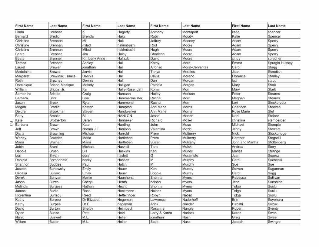
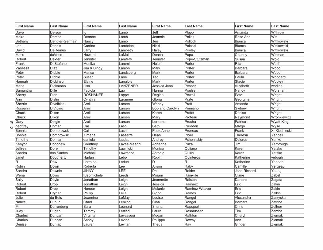
APPENDIX E Form Letters Received

This page intentionally left blank
E-2

First Name Last Name First Name Last Name First Name Last Name First Name Last NameKathleen A Gualtieri Susannah End Patricia Licea Georgina ReyesLana Abboud Elaina Ennouri Robert Lifson Georgina ReyesJudith Abel Hilary Entley Elaine Lindsey Sharon ReynoldsLeslie Abrahams Leslie Epperson Sergio Lion Sharon ReynoldsLaura Ackerman kristin erbach Filipa Loboa Heather ReynoldsKathleen Ackermann Stephanie Erickson Madeline Loder D RhewAlberto Acosta Patricia Ervin Thomas Logan Dale RhymerNorman Aguilar Dylan Escudier Patricia Long Francesca RicciAdriana Navarrete Aguinaga J Eskra Andria Lopez Kyra RiceKaren Ahn Dan Esposito Sandra Lord Megan Rice Humphriessharon ailstock Nicholas Esser Bettina Lorenz Betty RichardoneSharon Ailstock Joan Estes Bettina Lorenz Orion RidellaSharon Ailstock Gregory Esteve Bettina Lorenz michael rifkindsharon ailstock Gregory Esteve Bettina Lorenz Callie RileyTamadhur Al-Aqeel Maria Sonia Estrada-Solero A Lotsch Jen RiosDeborah Alderson Emily Ettinger A Lotsch Shann and Dennis RitchieAnn Alessi Vincenza Euripides Josephine Louie Castle RitterAnn Alessi Dinda Evans David Luboff Alberto Riverathomas alexander Luci Evanston Malgorzata Luciak Marisela RiveraJenna Allen Miranda Everett Diane Luck Barbara RobbinJulie Alley Miranda Everett nicolette ludolphi Terry Ellen RobinsonDonna Alleyne-Chin Mary Ewing John Lundquist Cheri RobinsonJeff Alonzo Fantina F Grant Lupher Maria Hagis RodriguezChoky Alvarez Amy F Erin Lynch Mary RojeskiDenise Alvera Yvonne Fast Maureen Lynch Jelica RolandCara Ammon Joy Fedele Maureen Lynch Jelica Rolandisabella amoroso Susan Fein Maureen Lynch Darsana RoldanAspen Amura Antonio Delgado Fenoy Pamela Lynn David RomportlCeleste Anacker Eline Fernandez Pamela Lynn David RomportlCeleste Anacker Rosendo Fernandez Pamela Lynn David RomportlJudith S Anderson T Fernandez Dolores B. Lynn Charlene RootGen Anderson Rosendo Fernandez Pamela Lynn Colleen RootsSandra Anderson Mary Lou Ferralli Pamela Lynn Michael RosenblumSusan Anderson Kevin Ferreira Denise Lytle Kristen RossTammy Andrews rebecca ferrell G M Diana RossRoger Angle Mauro Ferrero Angus m Macdonald Melissa RothenbergerChristine Angwin Dawn Ferro Angus Macdonald Kristen RothmanMartin Ansell Dawn Ferro Angus M Macdonald Nancy RoussyHarvey Arkin Jamie Fillmore Laura Macdonald Scott RubelSusan Armistead, M.D. scott finamore Eileen Macmillan Lisa RubinSusan Armistead, M.D. Jeffrey Findeis Susanne Madden Michael RubinsteinCharles Arnold Tom Finholt Justin Maddox Leana RudishAlison Arnold Rebecca Finley Marianne Maetz Susan RudnickiLee Arnold Elaine Fischer Evelyn Magalde Julia Ruff
E-3

First Name Last Name First Name Last Name First Name Last Name First Name Last Name
David Arnson Claudia Fisher Michelle Maing Julia RuffVance Arquilla Brendan Fisher Eugene Majerowicz lara RuffinattoDonna Arsenault Stasia Fisher Ira Mak Catherine RuggeriMatthew Ashmore Madeleine Fisher-Kern Adam Makhluf Margaret RunforsElyse Ashton Ted Fishman Qasim Makkani Cathy RupertiDavid Asselin Ashley Fisk Alex Makris Cathy RupertiDavid Asselin Maura FitzGerald Marco Malatesta Cathy RupertiNathan Atkins Stan Fitzgerald Marco Malatesta Michael RyanSilvia Ator Donna Flade Marco Malatesta Therese RyanJoanna Attard Dylan Flather Judy Malone Unnikrishnan SDavid Auerbach Joanna Fong Jace Mande deborah s van dammeSasha Auffrey Liliana Fonseca Celia Maness Angelique SaavedraJoann Aurand Pamela Fonseca Sherri Mann Nancy SagatelianJennifer Avellan Kathy Fontana Helen Manning-Brown Ed Sahagian-AllsoppRon Avila Michele Foote bjoern mannsfeld Charlotte SahnowJon Badgett William Forbes Christina Manos Bocek James SaleyJoe Badley David Ford Mark Mansfield Bruce SaltzerDiane Badley Lauren Ford Mark Mansfield Jeff Salvarynannette bailey R Forest Margherita Manzo Jeff SalvarynMichael Bailey Pietro Fornana Mary Marchetti Nancy SalvatierraAlicia Baker J.K. Fort-Strietzel Charbonnier Marie Maria SanchezLee Baldwin J. K. Fort-Strietzel Sandrine Markey Maria Sanchezcarol banever Fantina Fountouki Lynne Marko Maria SanchezJessy Barate Sesame Fowler Saul Markowitz Maria A SanchezTheresa Barbour Caroll Fowler Deborah Marks Kim SandholdtAngie Barker Zack Frank Patricia Marlatt Sam Sandilla JrNani Barnes Jan Frankl Dorrine Marshall Julie SanfordPatricia Barnhart marion frazier Jon Martell Ally SantaclaraLaurie Barre Lisa Fredsti Paul Martin Lori SantosHeather Barrera Eckart Freihöffer Marilyn Martin Evelyn SantosSteven Barrett Gianfranco Frelli Russell Martin Maria SanzSteven Barrett Gianfranco Frelli Helen Martin Sylvia SaraviaSteven Barrett Gianfranco Frelli Catherine Martin Margie SareSteven Barrett David Fremont-Smith Holly Martinell Dorrian SarrisSteven Barrett Jeanette French John Martinez Marlene SauerSara Barrientos Andrew Frey Melissa Martinez Brad SaundersSusan Barrons Shelley Fu Melissa Martinez Brad SaundersRobin Barstow Ettienne Fuentes Jr. Jennifer Martini Elizabeth SaveriHerb Bartel Kristina Fukuda-Schmid Tim Martinson Anne SawyerLisa Barth Kristina Fukuda-Schmid Kris Mashburn Lois SayersTina Bartle David and Audrey Funk Dawn Mason Manuela ScaliciRebecca Bartlett David and Audrey Funk Jill Masson Kelley ScanlonTodd Bartolomeo David and Audrey Funk Carole Mathews Sally SchenkerSandra Barton Eben Futral Anubhuti Mathur Sally Schenker
E-4

First Name Last Name First Name Last Name First Name Last Name First Name Last Name
Jennifer Bass Elysa G Dale Mattes Carol ScherickLarry Bassett Edward G. Mrkvicka Dale Mattes Lola SchiefelbeinJolianne Baum Kornelia Gaber Michael Mayo Gary SchlemmerMindi Baurer Carol Gabor Darius Mazaheri Henry SchlingerValerie Bavisotto Carol Gabor Darius Mazaheri Paul SchmittJo Baxter Mal Gaffney Susan Mazza Maria SchneiderCornelia Bayley Glenn Gallagher Mary McAuliffe Nancy SchuhrkeG Beam Peter Galvin Angela McBride Diane SchwanbeckSandra Beatty John Gambardella Ellen Mccabe Diane SchwanbeckElisabeth Bechmann Joshua Garcia Karen McChrystal Laura SchwindCary Becker Gloria Garcia Ted McClure L.D. ScottCarol Becker William Gardner Patty McCollim Joan ScottPeter Bedard Asa Gardner Douglas McCormick Belinda ScottKevin Beel Jamila Garrecht Edward McCoy Ann Marie ScottiDaniel Belachew David Garrett Cree McCree Amanda ScuderDaniel Belachew Darryl Garris Krystel McCullough Michael SeagerPatty Bell Esther Garvett Amy McDaniel Kerry SearleMarisa Beltrame Henry Gaudsmith Patricia McDonald Alisha SeatonNoel Bender Linda Gazzola Patricia McDonald Gil SeeberBetty Bender Linda Gazzola Brad McDonough Gil SeeberBetty Bender S George Maureen McGee Samantha SeegullMichelle Benes Charis george mike mcginn Ellen SegalMaria Benitez Inna Gergel Edwin McGrath Joyce SeligRichard Benson Inna Gergel Lisa McGuire Robert SeltzerGeorgia Benyk Camile Getter caephren mckenna Mark SentesyMarie-Ange Berchem Javier Eduardo Giachalla Velasco Kathy McLean MacKenzie SerpeFelice Berenson Grace Giammello Kathy McLean Ruth SerraBernie Berenson David Giantomasi Gay McLeod Ruth SerraPeter Berg Valerie Giddy Lynne Mcnamara Ruth SerraPatricia Bergh RN Camille Gilbert Lynne Mcnamara Jeff SevierEileen Bergmann Linda Gilbert Jacob McNeal Candace ShadboltDiane Berliner luron Gilberte Penny McNeil Hiten ShahTodd Berliner Anthony gilchriest Colleen McNulty Brijesh ShahMichael Berry Meagan Gill Blue McRight Mariam Shah-RaisHARRISON P BERTRAM J David Gillanders Alexandra Meador Daniel ShalitMichael Betancur Sharon Gillespie Irma Mejia Diane ShaughnessyDirk Beving Lilly Gillian Ron Melin S.S. ShawRussell Bezette Ken Gilliland Virginia Mellace S.S. ShawRussell Bezette Lance gimenez Katharine Mellors Gabriel SheetsChristine Biela Lance Gimenez Catherine Melvin Gabriel SheetsMichelle Billmaier Mark & Susan Glasser Catherine Melvin Dodie ShepardArmand Biron Margie Glod Massimiliano Mengoli Dodi SheparsShirley Biscotti Christina Golamis Billie Menier Melanie ShepherdKerri Bisner Christina Golamis Michael Mercadante Donna Shepherd
E-5
First Name Last Name First Name Last Name First Name Last Name First Name Last Name
O Bisogno Scotti Angela Goldberg Michele Mercer Richard ShermanAlan Bixler Georgia Goldfarb Michael Meredith Tawny SherrillAngela Black Viviam Gonzalez Robert Meredith Anne SherrillRichard Blain Michael Goode Robert Meredith Megan SherwoodRichard Blaine Luna Gooding Michael Merenda Ariel ShidloJill Blaisdell Ellen Goodman Sasha Meretzky Betty ShipleyJanet Blake Ellen Goodman Alison Merkel Linda Shishino-CruzSeana blake Christine Goodreau Margaret Merlin Timothy ShiversM Blanc claudine goossens Pamela Merriam Athena ShlienRollin Blanton Susan Goran Sobel Courtney Merritt Virginia ShontellMoran Bluestein Monika Gosteli-Gyger Nicholas Merry Michael ShoresRobin Blum Jaimie Gowatsky London Metcalfe H ShuklaJennifer Bock George Grace london metcalfe Ron ShultzTrina Bodine George Grace Colonel Meyer Todd ShumanParis Boehm Bettina Graf Barb Meyer Carole Shurtz HavelkaJustin Bonsey Guy Graham Kathleen Michaels Ann SiegelLes Borean lesley graham Raelyn Michaelson Suzy SiegmannDAVE BORKOWSKI SVEVA GRAMMATICO Raelyn Michaelson Nicole SilvaBarbara Boros Andreina Granado Alain Michaud Chad SilverSilvana Borrelli Joel Graves Shannon Milhaupt Ron SilverMarie Boschen William Gray Lesa Miller Mark SimpsonVic Bostock Dianne Gray Don Miller Joni SimsJenny Boulton Jonathon Green Ruth Miller Shravasti SinghJenny Boulton Rhonda Green Pamela Miller Therese SingletonStephane Bouthier Jason Green Dianne Miller Susan SinotteDanielle Bower Gallagher Green Elias Minakis Leno SislinHerley Jim Bowling Lucian Grey Steve Mineck lenore sivulichHeidi Bowman David Griggs Mark Mironov Ardis SkillettJules Box Dr & Mrs James Grimes Monique Misewicz Barb SkoogRod Boyd maria gritsch Denise Mitchell Kimberly SkrobizaJon Boyden James Grizzell Mitch Mitchell paul slapinskiLisa Mayr Boynton Michelle Gross Gosia Mitros Dana SlawsonLisa Mayr Boynton kortney groves Michael Moeller Adam SloanEliette Bozzola Rebecca Grundy Erika Mohos Nathan SmithGenevieve Brackett Snti Guallar Ingrid Mohr Larry SmithJennifer Bradley Kathleen Gualtieri RaeAnn Moldenhauer bernice smithJenny Bramlette Elizabeth Guapyassu Victoria Molinari stephane smithJenny Bramlette tanya guchi Marina Molnar Rich SmithJenny Bramlette Ayan Gudda Chatelain Mona Karen SnellTania Brandao Valerya Gurevich Sue Monaghan Sara SnyderTania Brandao Ana Gutierrez Kristin Monday Julia SolaRichard Brandes Nickolas Gutierrez Mauro Monia Julia SolaVicky brandt Janet Hackney Carolyn Monnet Mike SoshnickMisty Breaux Beverly Hadjikhani Dorthea Montaine Michael Spadoni
E-6
First Name Last Name First Name Last Name First Name Last Name First Name Last Name
Linda Brebner K Hagerty Anthony Montapert katie spencerBernard Bredig Brenda Haig Robin Moody Katie SpencerChristine Brennan Mi Hak Jeffrey Mooney Adam SperryChristine Brennan milad hakimbashi Rod Moore Adam SperryChristine Brennan Milad hakimbashi Hugh Moore Adam SperryBeate Brenner Jim Haley Charlene Moore Adam SperryBeate Brenner Kimberly Anne Halizak David Moore cindy sprecherTeresa Bressert Ashley Hall Kathy Mora Emma Spurgin HusseyLaurel Brewer jonathan Hall Alfonso Moral-Cervantes Carol StaggMadeleine Brewer Jarvis Hall Tanya Morales Jean StandishMargaret Brewinski Isaacs Dennis Hall Olivia Moreno Florence StanleyRuth Breznay Dennis Hall Dan Morgan laci stappDominique Briano-Mazique Melody Halligan Patricia Morgan Mary StarkWilliam Briggs, Jr. Kai Hally-Rosendahl Kona Mori Mary StarkSamantha Bristoe Craig Hamann Hatley Morison Peter StearnsBarbara Britz Lisa Hammermeister Rachel Morr Meghan StearnsJason Brock Ryan Hammond Rachel Morr Lori SteckervetzMegan Brodie Kristen Hampton Ann Marie Morris Charleen SteevesDeidre Brookman Steven Handwerker Ann Marie Morris Rose Marie StefBetty Brooks BILLI HANLON Jesse Morton Neal SteinerKate Brotherton Sarah Hanneken Richard Moser christina stembergerBarbara Brown Kate Harding John Moss Michael StempleJeff Brown Norma J F Harrison Valentina Mozzi Jenny StewartDiana Browning Michael Harrold Prem Mulberry Nick StockbridgeWendy Brueder Maria Hartleben Prem Mulberry Heather StogsdillMaria Bruinen Maria Hartleben Susan Mulcahy John and Martha StoltenbergJebin Bruni Michael Haskell Tara Mulski Andrea StoryDebbie Brush Bill Haskins Ken Mundy Marisa StrangeLori Bryan dora haslett G Muramoto Juan SuarezDaniela Brzobohata becky Hassett M Murphy Carol SucheckiShannon Buddes Paul Hatch M Murphy Sue SueJoseph Buhowsky Emily Hauer Ken Murray Steven SugarmanCecelia Bullard Emily Hauer Bobbie Murray Carol SuggDerek Bunyan Martin Haunhorst Shonna Myers Rebecca SullivanJason Burch Cheryl Heath nelson myers Jane SunshineMelinda Burgess Nathan Hecht Shonna Myers Tolga SusluJames Burks Ross Heckmann Nelson Myers Tolga SusluFlorentina Burlacu Reed Heffelfinger Robyn Nabat Tolga SusluKathy Burpee Dr Elizabeth Hegeman Lawrence Naderhoff Erin SuyeharaKathy Burpee Dr E hegeman Arick Naeder Hiroshi SuzukiDavid Burton Shelby Heimbach Rosanne Nangle Robert SventyDylan Busse Patti Held Larry & Karen Narlock Karen SwanNahid Buswell M.L. Heller jonathan Nash Greg SweelWiliam Butler M.L. Heller Scott Nass Joseph Swinger
E-7

First Name Last Name First Name Last Name First Name Last Name First Name Last Name
Anne Buttyan Michael Henderson Matthew Nasser Susan SwitzerNancy Byers Alec Hendrickson Peter Navarro Nataliya SyarovaNancy Byers Dakota Hennessey Michael Neary Jean-Charles SzostakNancy Byers lLloyd J. Herbert, Jr. Carrie Needler Brenna TOtto Cache Terri Herbst carrie needler Kenneth TabachnickOtto Cache Birgit Hermann Thomasena Negri-Leary Vincent TaborJanet Cade Dana Hershkowitz Dara Neidhardt Maria TalamantesMimchel Cagnetta Annie Hg Dara Neidhardt Marie Talbotkyle Calcagno Annie Hg Dara Neidhardt Jimy TallalLori Anne Callahan Janet Hicks Janet Neihart Jan TamotoMelinda Calvert Clark Hiestand Debbie Neimark Teresa TarinMelinda Calvert Lindi Higgins Debbie Neimark Emily TaylorMax Calvillo Helve Hiis Debbie Neimark James TaylorCath Campbell Lisa Hills Debbie Neimark Alison TaylorKaren Campbell Norman Hines Debbie Neimark Sara TaylorCath Campbell lance hlmenez Catherine Nelson Alison TaylorKaren Campbell Xuandai Hoang Bette Nelson Sara TaylorTom Canning Terri Hobba Aleeta Nelson Sara TaylorStacey Cannon Natalie Hodapp Catherine Nelson Sara TaylorPatricia Canterbury Rebecca Hoeschler Lisa Denise Nelson Sara TaylorIraida Capaccio T.A. Hoffman Bette Nelson Kyle Te PoelElaine Capogeannis Dianne Hoffman Bette Nelson Carol TenagliaMichele Caporaso Toni Holbrook Bette Nelson Laura TenenbaumHortencia Cardenas Walter Holdsworth Andrea Nemec William TepperTiziana Cardone Stephen Holland chris ness Karina TerraEdward Carey JWF Holliday Alice Neuhauser Chiara TestiBrenda Carey Candace Hollis-Franklyn Laura Nevins Chiara TestiJered Cargman Magnus Holmen Laura Nevins Chiara TestiElizabeth Carlisle Michelle Holmes Laura Nevins Joanne ThielenIan Carlon Celeste Hong Kim Newhart Mitsuka ThiemMargery Carman Kenneth Hope Diane Nezgoda Thomas Thirionlaura carmona-mancilla Alexandra Hopkins Carol Ng Laura ThomaeMichael Carney Lindy Hoppe Tuduyen Nguyen Ron ThomasJack Carone Steve Hosmer Patricia Nickles Tina ThomasGary Carpenter Alberta Householder Debra Nicols S ThompsonJay Carr Kristin Howard Susan Nicosia Michaoah ThompsonCarmen Carrasco Jessica Howell Turner Kis Bøggild Nielsen Julia ThompsonRicardo Carrera Jon Hoy Amir Niknam Dave TindelGreg Carter Donna Hoyer Christina Nilloe Priscilla TineWade A Carter Suzette Hoyt Jessica M-E Nitsch Tina TineCarl Cartwright Chuck Hugi Sandra Noah Jeff ToppingMauricio Carvajal Jacki Hunter Pam Nobuto Lynn TorMauricio Carvajal Jennifer hunter Jennifer Norman Heather TorbitMauricio Carvajal Lee Hutchings Susan Norton Alvan D Camacho Torres
E-8

First Name Last Name First Name Last Name First Name Last Name First Name Last Name
Brett Casper Frank Huttinger Vicki Nosal Alvan D Camacho TorresClaudida Cass Rachel Imholte Raymond Nuesch Jennifer TothClaudia Castillo Bonnie Ip Raymond Nuesch Ask TrainingAlan Castner Eric Isenhower Raymond Nuesch Holger TressinBarbara Caton Anna Isis-Brown Raymond Nuesch Jace TrimmerBarbara Caton Steve Iverson Raymond Nuesch Tia TriplettThomas Cavanagh Tonya Ivey Raymond Nuesch Mark TruscinskiEd Cavuto Tonya Ivey Rayleen Nunez Jackie TryggesethJane Cecil Donna J Rebekah O'Brien Jackie TryggesethShirley Cernos Lisbeth Jaasko Rick O'Bryan Sauwah TsangSheila Chaffins Danya Jablon Rebbeca Odle kevin tsuiSheila Chaffins Danya Jablon Rebecca Odle Kevin TsuiSheila Chaffins Lisa Jacobson Rebecca Odle Roy TuckmanMatt Chalfa S Janes Julie O'Donnell Paul TuffJoanne Challacombe Nina Janik Elizabeth O'Halloran Paul TuffJoy Chambers Susan Janow Carol Ohlendorf Paul TuffDanielle Charney Brenda Jaquez Kris Ohlenkamp Charles TullisJanet Chase Cyril Jay-Rayon Jan Oldham aiting tungLinda Chase Justin Jeannero hellen Oliveira Gabriella TurekBrandon Chavez Karen Jenne Kate Oliver Jessica Howell Turneralicia chen Nicole Jergovic Susan Olsen Patricia TurtleRichelle Ching nicole jergovic Diane Olson J. Gregory TwainBarbara Chitwood Donna Jerry Polly O'Malley Taner UcarSun Cho Darynne Jessler Abraham Omorenimwen Oboruemuh Taner UcarMathew Christianson Lance Jimneez Abraham Omorenimwen Oboruemuh Lisa UdelMaria Christopher Elizabeth Johansen J Orcutt E UngerIris Chynoweth Bettina Johl Brian O'Reilly Pamela UngerDon Cianelli Theodore Johns Dara orelick Massimiliano UrsoEleonora Ciccarelli Theodore Johns Wendy Orewyler Kenny VaherEleonora Ciccarelli Theodore Johns WENDY OREWYLER Alexis ValLoralee Clark Theodore Johns Vikki Orlando Alexis ValJanice Cleary Theodore Johns Vikki Orlando Damir ValecicqDiego Clemente Sue Johnson Carolyn Ormenaj A ValenciaAthena Clevenger Annelisa Johnson Carolyn Ormenaj E ValenciaGordon Clint Penny Johnson Carolyn Ormenaj Melinda Van beekCindy Cobb Caryle Johnson Carolyn Ormenaj kieren van den blinkH. Coetzee Jessica Johnston Carolyn Ormenaj Kieren Van den blinkDonna Coffey frederique joly Edward Ornitz Joshua Van DeventerDonna Coffey V. & B. Jones Nancy Orons Patricia van HartesveldtCameron Coffman Mike Jones Erin O'Rourke Anne van OppenBrenda Colbert M Jones John Orsini Sandra Van ZantMartha Colella Hiroko Jones Ray Ortiz Roberta VandeheyFlynn Coleman Hiroko Jones Leslie Osborne Ron VanderfordMary Coleman Kyana Jones Katherine Oshana Charlotte Vardan
E-9

First Name Last Name First Name Last Name First Name Last Name First Name Last Name
Minturn Collins Hiroko Jones Roy Oshita marcela vasquezgeoffrey Collins Hiroko Jones Adam Ostler Ileana VasquezAmanda Collins Michelle Jones Adam Ostler Margaret VasutGinamarie Colorio Michelle Jones Barbara Ostrowski Satya VayuSara Colton Sandra Joos Fabienne Oubrayrie Christina VelasquezCarla Compton Hadi Jorabchi Fabienne Oubrayrie Christina VelasquezCarla Compton Eric Jorgensen Fabienne Oubrayrie Petra VeneriIlaria Conconi Ana Jude Christophe Ouedec Christine VentenillaAlan Conklin Lauren Jusek Gary Overby Christine VentenillaAnna Connolly Jennifer Kaiser Amanda Overstreet Evelyn VerrillShirley Conroy Jessica Kalanick Van Oxley Jackie VescioThomas Conroy Ray Kalinski Susan P. Vessicchiuo Phoenix VieFaith Conroy Zee Kallah Melinda Padgett Sharon Viethklouise cook Frank Kalman Melinda Padgett m.m. VillaMaggie Cook Frank Kalman Melinda Padgett m.m villaJan Cooke Lee Kanthoul Evan Page Blake ViolaCharlene Cooper Nolan Kappelman Natalia Palacios Jamie VirgiliCharlene Cooper Jennifer Kardos Michelle Palladine Dante VittorelliPenelope Cooper-Kelley Ann-Kristin Karling Giancarlo Panagia Terry VollmerSean Corrigan Kent Karlsson Corey Pane Joe and Mary VolpeDr. Robert Cospito katie karras Cheri Pann Ma WDr. Robert Cospito Ruwange Karunaratna Gina Pantier Celeste WMaurice Costa Lynne Kastner Gina Pantier Frank WagnerMaurice Costa Lynne Kastner Brian Pappas Linda WaineDonna Cottrell Renata Kater Patrizio Paratelli Aurea WalkerCharles Couch Michael Katz Patrizio Paratelli Craig WalkerCharles Couch Martha Rosalie Kaufman Jai Parekh Scott WalkerCathy Cousins Laura kaufman Jai Parekh Kathy WallAdelina Covaci Deborah Kavruck Roger Pariseau Victoria and David WallaceKim Cox Paul Keables Jason Park Amber WallaceWm Crafts Christina Keach Mary Parker Aleta WallachLaura Craig Thomas Keenan David Parker Hunter WallofMaggie Cramer Marie Kelly David Parker Hunter WallofMark Crane Maria Kelly Diane Parmeter Hunter WallofDonna Crane Bruce Kendall Michael Parsons Nathan WalworthMark Crane Janet Kennington Adam Pastula Tim WarnerScott Crockett Brian Kessler Marina Peake Ronald WarrenJim Cromeenes Michael & Kathryn Kevany Marina Peake Rose WascheWilliam Cromwick JEANNE KEVER Erwin Pearlman Danuta WatolaWilliam Cromwick Reema Khan Kelle Peeplez Angela WatsonThomas Crothers Jennifer Killian Joshua Pelleg Ann WattersRobert Crum Kathryn Kind Daniel Pelletier Sheila WattsCathy Crum Barbara King María Pellicer Don WebbKylie Cullen Barbara King María Pellicer Heidi Weber
E-10

First Name Last Name First Name Last Name First Name Last Name First Name Last Name
Debra Cunningham Mandu King brian peltier Lori WeberConnie Curnow Barbara King Roberto Penaherrera Jan WeberAmanda Curry Jade Kiran Deborah Pendrey Chris WeeksCatherine Curtis Jade Kiran Stanley Pendze Ans WeeversSandy Cvijanovic Suzanne Kirby E Perkins Richard WegmanRosemary Cyr Michelle Kirk Rachel Perlman Melanie WeinsteinDavid Czamanske Kaye Kirkwood Francis Perlman Jerry and Donna weinstockDiane D M Kiser Jill Pern Kristen WeissScott Dale Deering Nancy Kissock jonathan Peter Stephen WeitzLisa Daloia Richard Kite Peggy Peters Joanna Welch LaskenMelissa Dalton Deanna Kizis Susan Peters Jeannette WellingRhea Damon Marcy Klapper John Petersen Jennifer WellingsJerry Daniel Marcy Klapper JM Peterson Susan WellsCourtney Daniels Craig Kleber George Petrisko Caitlin WelshStacey Daniels-Dattilo Tracey Kleber Tami Petty Caitlin WelshJohannis Danielsen Daniel Knecht Jamaka Petzak Tom WenzelMelinda Dastrup John Koenig Horst Pfand F. Robert WesleyBetty David William Lee Kohler Horst Pfand Shane WesternA Davis Amala Kohler Mindy Pfeiffer John Whalenchelsea davis Bodhi Kohler Mindy Pfeiffer Patty WheelerAngelika Davis John Koperczak Christina Pham Jessica WheelerBillie Dawson Tara Korb Yen Pham L WhippleKatie Dawson Inga Kornev Brenda Philipsen Michael WhiteAnna-Maria D'Cruz Terry Kourda E. Lehuanani Phillips Kat WhiteChantal De Geest Laura Kowal Kaelyn Phillips Michael WhiteVictoria De Goff T Kowitt Francoise Phipps Catherine WhitmoreFrancois de la Giroday laura krause Arielle Phoenix Katherine WhitsonCarolyn De Mirjian Fred & Sara Krauthamer Elizabeth Piburn Deanna WiemarCarolyn De Mirjian Kevin Kreiger Pille Pierre-Louis Deanna WiemarCarolyn De Mirjian Donald Krotser Brian Pierson Sunni WigandRachel de Rougemont K Krupinski Thomas Pierson Faith WilcoxRachel de Rougemont Kelly Kulauzovic Lissa Pierson Gillian WilkersonDarin De Stefano Linda Kurtz Evelio Pina Paul WilkinsKristopher Deapen Kim La Chance Jacqueline Pineda Christina WilliamsHellen DeAssis Suzanne La Muniere Cristiano Pinnow F WilliamsEvelyn DeBaun Jason LaBerge Meryl Pinque Davina WilliamsJohn Deddy Mercedes Lackey Janna Piper Davina WilliamsDiana Dee Roberta LaFrance Janna Piper Jen WillisDiana Dee Alexandre Lagreou janna piper bennye willisDiana Dee Alexandre Lagreou Janna Piper Marianne WilsonDiana Dee Alexandre Lagreou Danielle Pirotte David WilsonDiana Dee Caitlyn Lajoie Danielle Pirotte Joseph WincekMaria Deliou Alison Lake Massimo Pistarino Joie WinickMaria Deliou Jessica Lam Tom Pitman Carol Winkler
E-11
First Name Last Name First Name Last Name First Name Last Name First Name Last Name
Dave Delson K Lamb Jeff Plapp Amanda WithrowMoira Demos Deanne Lamb Jeannie Pollak Rose Ann WittBethany Dengler-Germain Nancy Lamb Jeri Pollock Bianca WittkowskiLori Dennis Corrine Lambden Nicki Poloski Bianca WittkowskiDavid DeRemus Larry Lambeth Haley Pooley Bianca WittkowskiMace deVries Howard LaMell Donna Pope Charley WittmanRobert Dexter Jennifer Lamfers Jennifer Pope-Stutzman Susan WoldFrank Di Stefano Monika Lamml Helen Porter Rita WolffVanessa Diaz Jim & Cindy Lamon Mark Porter Barbara WoodPeter Dibble Marisa Landsberg Mark Porter Barbara WoodPeter Dibble Susan Lane Ted Porter Paula WoodardHannah Dickinson Elaine Langlois Mark Porter Stacie WooleyMaria Dickmann Lisa LANZENER Jessica Jean Posner elizabeth worlineSamantha Dille Fabiola Lao Hanna Poulsen Nancy WorshamSherry Dion ROSHANEE Lappe Regina Powell Pete WrightAnn Distin Cynthia Laramee Gloria Prate Georgina WrightSherrie Divelbiss Areil Larsen Wendy Pratt Amanda WrightRoseann DiVicino Areil Larsen Bob and Carolyn Primiano Sydney WrightChuck Dixon Areil Larsen Karen Profet Denise WrightChuck Dixon Areil Larsen Mary Proteau Raymond WronkiewiczGary Dolgin Areil Larsen Lorraine Prucha Patrice Wyatt-Kinggeoffrey Doman Cal Lash Beth Prudden Margo WyseBonnie Dombrowski Cal Lash PauleAnne Pruneau Frank X. KleshinskiBonnie Dombrowski Ximena Lasserre Dean Pryer Theresa YandellTimothy Domian daniela laudati Andrey Pshenitskiy Delores YankoKenyon Donohew Courtney Laves-Mearini Adrianne Puza Jim YarbroughJeffrey Dorer Timothy Lawnicki Monica Quijano Karen YatskoSandra dos Santos Michael Lawrence Antonio Quilici Karen YatskoJanet Dougherty Harlan Lebo Robin Quinteros Katherine yeboahR Dow Lorraine Leduc D R Katherine YeboahRobin Down Roberta Lee Alison Raby Camille YergeauSandra Downie JINNY LEE Phil Raider John Richard YoungWena Dows Kleomichele Leeds Miriam Rainville Claire ZabelSally Doyle Jonathan Leigh Jeannette Ralston Darlene ZagataRobert Drop Jonathan Leigh Jessica Ramirez Eric ZakinRobert Drop Honour Leigh Melanie Ramirez-Weaver Eric ZakinRobert Dryden Phillip Leija Sigrid Ramos Eric ZalkinJulie du Bois Jeannine LeMay Louise Rangel Alexandra ZarzyckaNance Dubuc Chad Leming Gina Rangel Barbara ZatrineM Dürrenberg Sara Leonard Shana Rapoport Chris ZellnerJudy Dugan Tammy Lettieri Laura Rasmussen Tim ZembaCharles Duncan Virginia Levasseur Megan Rathfon Cheryl ZiemakCharles Duncan Sandy Levine Philippe Raway Ann ZiemakDenise Dunlap Lauren Levitan Theda Ray Ginger Ziemak
E-12

First Name Last Name First Name Last Name First Name Last Name First Name Last Name
stefan dwornik Michael Levitt Mark Reback Arlene ZimmerDavid Dyre Michael Levitt Rod Rediger Helene ZimmermanPam Eastwood robert Levitt Miho Reed Christine ZimmermanChris Eaton michael levitt Louis Reginato Jr Susan ZimmermanLinda Eberle Candace Lewandowski Cathy Reich John ZimmermannTerri Eddings Rena Lewis Heidi Reinhard Margaret ZochJeremy Eggerman Katherine Lewis Judith Reinsma Matt ZolaEdwin Ek O Lewis Angela Rennison Matt ZolaSusanne Ekberg Courtney Lewis Kristen Renton Carlo ZucchiSusanne Ekberg courtney lewis marisa reple Philip Zurflufshellsy ellis Dominic Libby Jana Repova Alison ZylaKyle Embler Patricia Licea Teresa Rex m k
S H Dr DieselDr Hegeman
E-13

Presidential Substation Project F-1 ESA / 207584.02
(A.08-12-023) Final Environmental Impact Report March 2013
APPENDIX F Mailing List

Appendix F
Mailing List
Presidential Substation Project F-2 ESA / 207584.02
(A.08-12-023) Final Environmental Impact Report March 2013
MASTER MAILING LIST: AGENCIES, ORGANIZATIONS AND INDIVIDUALS
SENT A HARD COPY OF FINAL EIR VIA OVERNIGHT DELIVERY SERVICE
Agency/Organization/ Jurisdiction Name, Title Street City, State, Zip Code
LEAD AGENCY/APPLICANT California Public Utilities Commission Juralynne Mosley, Project Manager 505 Van Ness Avenue Area 4-a San Francisco CA 94102 California Public Utilities Commission Hallie Yacknin, Administrative Law Judge 505 Van Ness Avenue Area 4-a San Francisco CA 94102 Southern California Edison Company Christine McLeod, Project Manager 2244 Walnut Grove Avenue Quad 3D,
388L Rosemead CA 91770
Southern California Edison Company Case Administration 2244 Walnut Grove Avenue, Rm. 321 Rosemead CA 91770 Southern California Edison Company Tammy Jones 2244 Walnut Grove Ave./ PO Box 800 Rosemead CA 91770
LIBRARIES Grant R. Brimhall Library 1401 E. Janss Road Thousand Oaks CA 91362 Moorpark City Library 699 Moorpark Avenue Moorpark CA 93021 Simi Valley Library 2969 Tapo Canyon Simi Valley CA 93063
CPUC SERVICE LIST Alston and Bird LLP Robert D. Pontelle 333 South Hope St., 16th Floor Los Angeles CA 90071 City of Moorpark Joseph R. Vacca 799 Moorpark Avenue Moorpark CA 93021 City of Simi Valley Paul Miller 2929 Tapo Canyon Road Simi Valley CA 93094-1912 City of Thousand Oaks Andrew P. Fox 2100 Thousand Oaks Blvd. Thousand Oaks CA 91362 City of Thousand Oaks Christopher G.Norman 2100 Thousand Oaks Boulevard Thousand Oaks CA 91362 Douglass & Liddell Donald C. Liddell 2928 2nd Avenue San Diego CA 92103 Goodin MacBride Squeri Day & Lamprey LLP
Michael B. Day 505 Sansome Street, Suite 900 San Francisco CA 94111-3133
Ranco Madera HOA William Gantzer 986 Lincoln Ct. Simi Valley CA 93065 Reich Radcliffe & Kuttler LLP Marc G. Reich, ESQ; Beth S. Kuttler, ESQ 4675 MacArthur Court Suite 550 Newport Beach CA 92660 Resident - Olsen RD Margie M. Overton 1508 Calle Fidelidad Thousand Oaks CA 91360 Resource Management Agency Kari Finley 800 S Victoria Ave Ventura CA 93009-1740 California Energy Markets 425 Divisadero Street, Suite 303 San Francisco CA 94131 Caterine A. Adler 771 Brossard Dr. Thousand Oaks CA 91360 F. Christopher Hansing 4656 Read Road Moorpark CA 93021 Gaston and Lesette Monast 5006 Read Road Thousand Oaks CA 93021-8765 George & Debra Tash 5777 Balcom Canyon Road Somis Valley CA 93066 Harvey Corr 4914 Read Toad Moorpark CA 93021 Helen Mary and Rebecca Sullivan 2028 Kirtland Circle Thousand Oaks CA 91360 James N. Assalley 1915 Maya Pradera Lane Thousand Oaks CA 93021 Jay Brewer 4991 Read Road Thousand Oaks CA 93021 Jeni Brown 3678 Sunset Valley Road Moorpark CA 93021 Jennifer L. Crandall, DDS 4656 Read Road Moorpark CA 93021 John Tanner 7255 Crest Rancho Palos Verdes CA 90275 Jon & Sharon Fleagane 4954 Read Road Moorpark CA 93021 Kelly Lobez 3678 Sunset Valley Road Moorpark CA 93021 Lehua Custer 4956 Read Road Moorpark CA 93021 Lily Sweet Wu 23 Braemar Ct Parsipanny NJ 07054-2456 Marco and Teresa Todesco 331 Laguna Terrace Simi Valley CA 93065 Marie Meyers 3678 Sunset Valley Road Moorpark CA 93021 Marissa Festerling 3678 Sunset Valley Road Moorpark CA 93021 Mark and Deborah Cassar 3678 Sunset Valley Road Moorpark CA 93021 Mark Bruce 1140 Adirondack Ct Simi Valley CA 93065 Martin A. Josephson 4906 Read Road Moorpark CA 93021 Richard and Rebecca Voskanian 4946 Read Road Moorpark CA 93021 Stephen Gibson 4912 Read Road Moorpark CA 93021 Teresa Chiu 1320 Miravalle Avenue Los Altos CA 94024 Walter Marchbanks 5000 Read Road Thousand Oaks CA 93021

Appendix F
Mailing List
Presidential Substation Project F-3 ESA / 207584.02
(A.08-12-023) Final Environmental Impact Report March 2013
MASTER MAILING LIST: AGENCIES AND INDIVIDUALS SENT A COMPACT DISC (CD) OF FINAL EIR VIA UNITED STATES POSTAL SERVICE
Name Title Agency/Organization Street City, State, Zip Code
Jonathan Evans Toxics and Endangered Species Campaign Director, Staff Attorney
Center for Biological Diversity 351 California St., Ste. 600 San Francisco CA 94104
David Bobardt Community Development Director City of Moorpark 799 Moorpark Ave Moorpark CA 93021
Robert Huber Mayor City of Simi Valley 2929 Tapo Canyon Road Simi Valley CA 93063
Mark Towne Deputy Director/City Planner City of Thousand Oaks 2100 E. Thousand Oaks Blvd. Thousand Oaks CA 91362
Ben Emami Engineering Manager II County of Ventura Public Works Agency
800 South Victoria Ave. Ventura CA 93009
Andrea Ozdy Land Conservation Act Planner County of Ventura, Planning Division
800 South Victoria Avenue L-1740
Ventura CA 93009
Derrick Wilson Staff Services Manager, Integrated Waste Management Division
County of Ventura, Public Works Agency
800 South Victoria Ave. Ventura CA 93009
Daniel Blankenship Department of Fish and Game P.O. Box 211480 Newhall CA 91322
Dianna Watson Department of Transportation 100 Main Street, MS #16 Los Angeles CA 90012
Katy Sanchez Native American Heritage Commission
Native American Heritage Commission
915 Capitol Mall, Room 364 Sacramento CA95814
Paul Edelman Deputy Director, Natural Resources and Planning
Santa Monica Mountains Conservancy
9750 Ramirez Canyon Rd Malibu CA 90265
Charles and Sheryl Cronin Co-Founder sTTop 1912 Maya Pradera Moorpark CA 93021
Diane Noda Field Supervisor U.S. Fish and Wildlife Service 2493 Portola Road, Suite B Ventura CA 93003
Alicia Stratton Ventura County Air Pollution Control District
669 County Square Drive Ventura CA 93003
Linda Parks Supervisor, Second District Ventura County Board of Supervisors
625 West Hillcrest Thousand Oaks CA 91360
Tom Wolfington Permit Manager Ventura County Watershed Protection District
800 South Victoria Ave. Ventura CA 93009
Alison Merkel 5 Meadowlark Lane Oak Park CA 91301
Andy Gosser 1574 Calle Artigas Thousand Oaks CA 91360
Betty Evans 1382 Calle Fidelidad Thousand Oaks CA 91360
Charlotte Watters 1590 Calle Artigas Thousand Oaks CA 91362
Corene Hansen 3208 Starfire Ave Thousand Oaks CA 91360
Craig Underwood 1010 Rosada Crt. Camarillo CA 93010
Danila Oder 530 S. Kingsley Dr. #402 Los Angeles CA 90020
Dennis Broersma 1540 Calle Fidelidad Thousand Oaks CA 91360
Donald Harrington 876 Warren Cr. Moorpark CA 93021
Elizabeth Groden 14164 Huron Ct Moorepark CA 93021
Gabriel and Silvia Scally 1577 Calle Artigas Thousand Oaks CA 91360
Gary Morse 1589 Calle Artigas Thousand Oaks CA 91360
George Pappas 1424 Calle Fidelidad Thousand Oaks CA 91360
Georgette McBreen 4179 N. Cedarpine Ln. Moorepark CA 93021
Ginger Brandenburg 1547 Calle Fidelidad Thousand Oaks CA 91360
Heidi Dauwalter 2918 Rosette St Simi Valley CA 93065
Jennie Crowley 1486 Calle Fidelidad Thousand Oaks CA 91360
Kim Halizak 1933 N.Beachwood Dr. #205 Los Angeles CA 90068
Kristi Brumle 1520 Calle Fidelidad Thousand Oaks CA 91360
Laura Wilson 390 Somerset Circle Thousand Oaks CA 91360
Lily Wu 1924 Maya Pradera Lane Moorpark CA 93021
Louise Meisterling 1432 Calle Artigas Thousand Oaks CA 91360
Marjorie Herring 3240 Sunset Valley Road Moorpark CA 93021
Appendix F
Mailing List
Presidential Substation Project F-4 ESA / 207584.02
(A.08-12-023) Final Environmental Impact Report March 2013
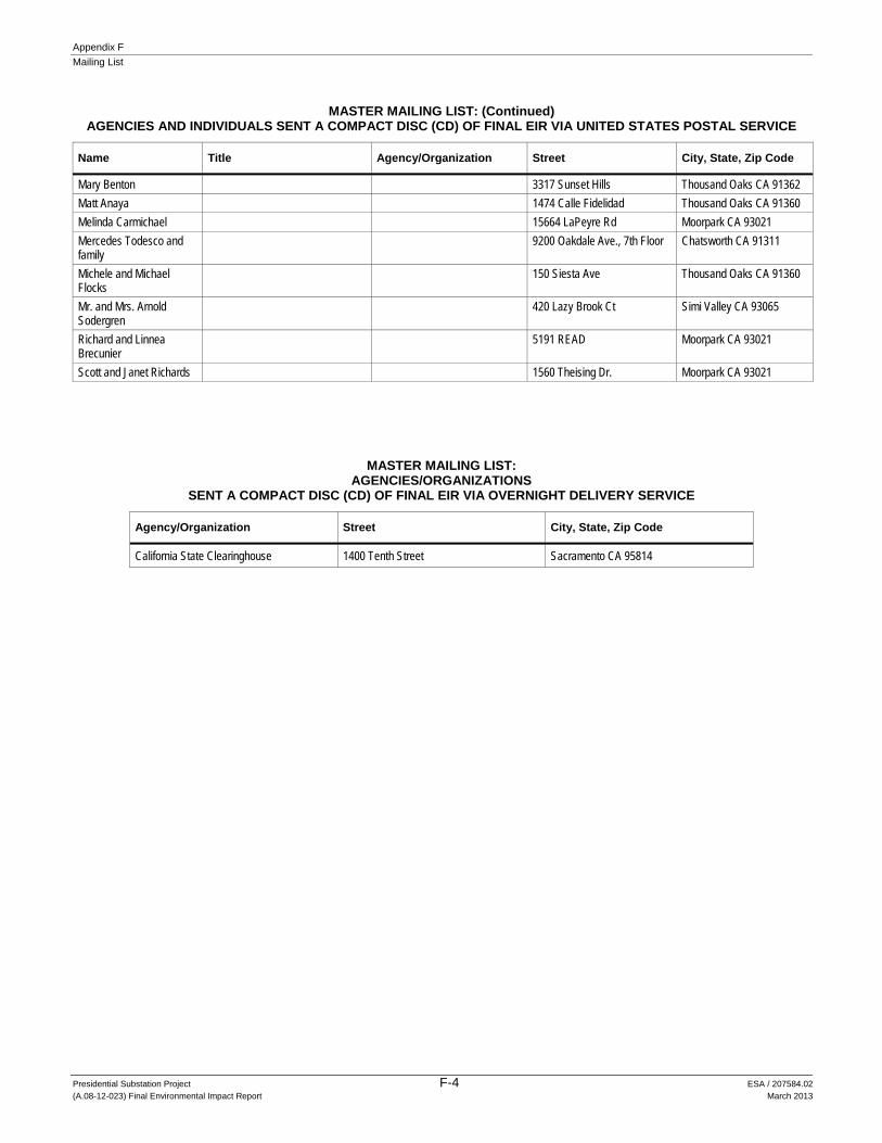
MASTER MAILING LIST: (Continued) AGENCIES AND INDIVIDUALS SENT A COMPACT DISC (CD) OF FINAL EIR VIA UNITED STATES POSTAL SERVICE
Name Title Agency/Organization Street City, State, Zip Code
Mary Benton 3317 Sunset Hills Thousand Oaks CA 91362
Matt Anaya 1474 Calle Fidelidad Thousand Oaks CA 91360
Melinda Carmichael 15664 LaPeyre Rd Moorpark CA 93021
Mercedes Todesco and family
9200 Oakdale Ave., 7th Floor Chatsworth CA 91311
Michele and Michael Flocks
150 Siesta Ave Thousand Oaks CA 91360
Mr. and Mrs. Arnold Sodergren
420 Lazy Brook Ct Simi Valley CA 93065
Richard and Linnea Brecunier
5191 READ Moorpark CA 93021
Scott and Janet Richards 1560 Theising Dr. Moorpark CA 93021
MASTER MAILING LIST: AGENCIES/ORGANIZATIONS
SENT A COMPACT DISC (CD) OF FINAL EIR VIA OVERNIGHT DELIVERY SERVICE
Agency/Organization Street City, State, Zip Code
California State Clearinghouse 1400 Tenth Street Sacramento CA 95814

Presidential Substation Project G-1 ESA / 207584.02
(A.08-12-023) Final Environmental Impact Report March 2013
APPENDIX G Certificate of Service

Appendix G
Certificate of Service
Presidential Substation Project G-2 ESA / 207584.02
(A.08-12-023) Final Environmental Impact Report March 2013
This page intentionally left blank


Presidential Substation Project H-1 ESA / 207584.02
(A.08-12-023) Final Environmental Impact Report March 2013
APPENDIX H Data Responses 7, 8, 9, and 10 Non-Confidential

This page intentionally left blank
H-2

Southern California EdisonPresidential Substation Project A.08-12-023
DATA REQUEST SET Presidential ED-07
To: ENERGY DIVISIONPrepared by: Saeed Sadeghi
Title: Project Engineer Dated: 02/24/2012
Question 01:
Response to Comments and Final EIR
The following comments from SCE provided in their table submitted to the CPUC on December 9, 2011, require clarification in order to be incorporated into the FEIR. The comment numbers relate to comments from the SCE table:
Comment 1: Pertaining to site acreage. Our understanding is that the Proposed Presidential Substation Site would require SCE to purchase a 5.4 acre parcel. However, the maximum footprint of disturbance would be 4 acres (hence the consistent use of “4-acre site”). This is consistent with the application and construction drawings. Provide either confirmation of this assumption, or additional detail to support disturbance of an area greater than 4 acres.
Response to Question 01:
The gross acreage of the purchased land is 5.4. Of this, 0.134 acre is dedicated to the street acceleration/deceleration to access the substation. Additionally, 2.33 acres of land is estimated to be disturbed for the substation construction which includes 1.36 acres within the substation walls and the remaining approximately 1 acre for such things as slope stabilization, catch basin, etc. In summary, the total land disturbance is estimated to be approximately 2.5 acres.
H-3

Southern California EdisonPresidential Substation Project A.08-12-023
DATA REQUEST SET Presidential ED-07
To: ENERGY DIVISIONPrepared by: Kendra Heinicke
Title: Estimator Dated: 02/24/2012
Question 02:
Response to Comments and Final EIR
The following comments from SCE provided in their table submitted to the CPUC on December 9, 2011, require clarification in order to be incorporated into the FEIR. The comment numbers relate to comments from the SCE table:
Comment 65: Based on conceptual engineering referenced in comment, please provide a map showing where overhead facilities are expected to occur on both sides of the roadway.
Response to Question 02:
SCE is not able to provide mapping at this time due to the fact SCE has not engineered this alternative route. It is expected, however, overhead facilities would occur on both sides of the roadway due to required guying or to avoid obstacles such as vegetation. For example, poles located in a curve or on a corner will typically require guying. (See Presidential ED-03 (Part 3) Question 50 for previous information provided regarding guying). Typically, guying consists of a guy wire (down guy) attached to a buried anchor, or when there is not adequate space for the required down guy, a shorter guy pole is typically placed with a down guy and buried anchor in a location that has sufficient room for these facilities. For example, if the guy wires would need to be placed in an area that is used by vehicles, a guy pole would instead be placed on the opposite side of the road to clear the roadway. To minimize the number of guy wires crossing the road, the subtransmission alignment could be designed to cross the roadway at certain locations so that most ,or ideally all, of the guying would be located on the same side of the roadway as the subtransmission line. In addition, the subtransmission line may need to cross the road at right angles to avoid vegetation or other obstacles.
H-4

Southern California EdisonPresidential Substation Project A.08-12-023
DATA REQUEST SET Presidential ED-07
To: ENERGY DIVISIONPrepared by: Rodney Porter
Title: Planner Dated: 02/24/2012
Question 03a:
Response to Comments and Final EIR
The following comments from SCE provided in their table submitted to the CPUC on December 9, 2011, require clarification in order to be incorporated into the FEIR. The comment numbers relate to comments from the SCE table:
Comment 67* (and several others) (* Per confirmation from ESA to SCE on 3/1/12, while SCE’s Comment 67 pertained to Alternative Alignment 3, SCE is to respond to the question in reference to Alternative Alignment 3 ) : In regards to Alternative Alignment 3. Please perform and provide the results of a wind loading study for installing a telecommunications line on the existing distribution poles from the intersection of Sunset Valley Road and Read Road east to the Proposed Presidential Substation If the results of the wind loading study determine that under Alternative Alignment 3, it would be necessary to replace existing 16 kV distribution poles between Sunset Valley Road and the Proposed Substation in order to support the installation of a telecommunications line please provide the following:
a. In a latter comment (Comment 182), SCE stated that the telecommunications line would not be installed in the duct bank. Please explain whether this is an engineering constraint or not.
Response to Question 03a:
3. In regards to Alternative Alignment 3, wind loading calculations have been performed for the existing distribution poles from the intersection of Sunset Valley Road and Read Road east to the proposed Presidential Substation. The wind loading calculations determined that all the poles that were calculated "passed" - meeting or exceeding the minimum safety factor required with the addition of the proposed telecommunication line being installed on them. 3a. There would not be an engineering constraint to install the telecommunications line inside the proposed subtransmission duct bank, based on the Alternative Alignment 3 design.
H-5

Southern California EdisonPresidential Substation Project A.08-12-023
DATA REQUEST SET Presidential ED-07
To: ENERGY DIVISIONPrepared by: Jack Haggenmiller
Title: Field Engineering Project Manager Dated: 02/24/2012
Question 03b:
Response to Comments and Final EIR
The following comments from SCE provided in their table submitted to the CPUC on December 9, 2011, require clarification in order to be incorporated into the FEIR. The comment numbers relate to comments from the SCE table:
Comment 67* (and several others) (* Per confirmation from ESA to SCE on 3/1/12, while SCE’s Comment 67 pertained to Alternative Alignment 3, SCE is to respond to the question in reference to Alternative Alignment 3 ) : In regards to Alternative Alignment 3. Please perform and provide the results of a wind loading study for installing a telecommunications line on the existing distribution poles from the intersection of Sunset Valley Road and Read Road east to the Proposed Presidential Substation If the results of the wind loading study determine that under Alternative Alignment 3, it would be necessary to replace existing 16 kV distribution poles between Sunset Valley Road and the Proposed Substation in order to support the installation of a telecommunications line please provide the following:
b. Describe the types of poles to be installed, including estimated heights.
Response to Question 03b:
The results of the wind loading study determined that under Alternative Alignment 3, it would not be necessary to replace any of the existing 16 kV distribution poles between Sunset Valley Road and the Proposed Substation in order to support the installation of a new telecommunicaitons line. Therefore, there are no types of poles to be installed that can be described.
H-6
Southern California EdisonPresidential Substation Project A.08-12-023
DATA REQUEST SET Presidential ED-07
To: ENERGY DIVISIONPrepared by: Adolfo Espino
Title: Engineer Dated: 02/24/2012
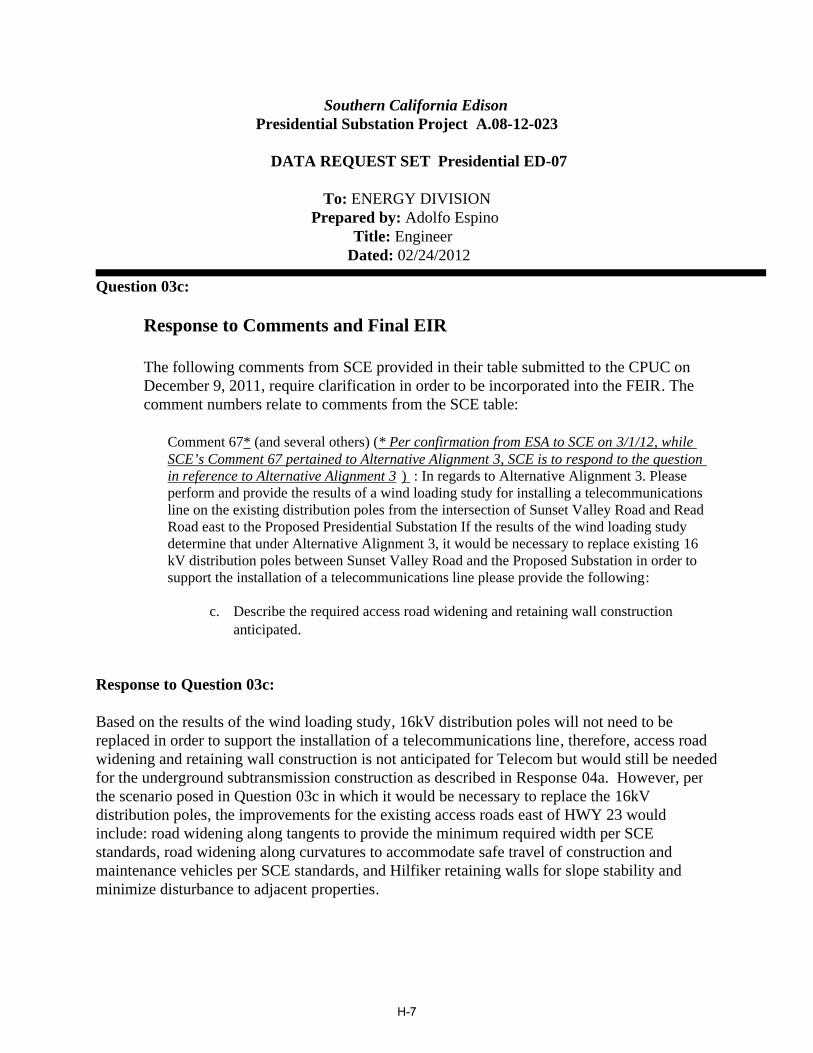
Question 03c:
Response to Comments and Final EIR
The following comments from SCE provided in their table submitted to the CPUC on December 9, 2011, require clarification in order to be incorporated into the FEIR. The comment numbers relate to comments from the SCE table:
Comment 67* (and several others) (* Per confirmation from ESA to SCE on 3/1/12, while SCE’s Comment 67 pertained to Alternative Alignment 3, SCE is to respond to the question in reference to Alternative Alignment 3 ) : In regards to Alternative Alignment 3. Please perform and provide the results of a wind loading study for installing a telecommunications line on the existing distribution poles from the intersection of Sunset Valley Road and Read Road east to the Proposed Presidential Substation If the results of the wind loading study determine that under Alternative Alignment 3, it would be necessary to replace existing 16 kV distribution poles between Sunset Valley Road and the Proposed Substation in order to support the installation of a telecommunications line please provide the following:
c. Describe the required access road widening and retaining wall construction anticipated.
Response to Question 03c:
Based on the results of the wind loading study, 16kV distribution poles will not need to be replaced in order to support the installation of a telecommunications line, therefore, access road widening and retaining wall construction is not anticipated for Telecom but would still be needed for the underground subtransmission construction as described in Response 04a. However, per the scenario posed in Question 03c in which it would be necessary to replace the 16kV distribution poles, the improvements for the existing access roads east of HWY 23 would include: road widening along tangents to provide the minimum required width per SCE standards, road widening along curvatures to accommodate safe travel of construction and maintenance vehicles per SCE standards, and Hilfiker retaining walls for slope stability and minimize disturbance to adjacent properties.
H-7

Southern California EdisonPresidential Substation Project A.08-12-023
DATA REQUEST SET Presidential ED-07
To: ENERGY DIVISIONPrepared by: Adolfo Espino
Title: Engineer Dated: 02/24/2012
Question 04:
Response to Comments and Final EIR
The following comments from SCE provided in their table submitted to the CPUC on December 9, 2011, require clarification in order to be incorporated into the FEIR. The comment numbers relate to comments from the SCE table:
Comment 70 (and several others): Alternative Subtransmission Alignment #3 – Explain the conditions under which the Hilfiker wall widening of access roads would be required and what specific construction components it pertains to, specifically is it associated with undergrounding, or installation of poles. It was previously explained that the access road widening and installation of the Hilfiker wall was associated with the installation of new subtransmission poles and not necessarily associated with the undergrounding activities. For Alternative Alignment 3 Specifically:
a. If the existing 16 kV poles did not need to be replaced, would the access road need to be widened? If yes, describe and explain why.
b. If the existing 16 kV poles did not need to be replaced, would the Hilfiker wall be required? If yes explain why.
Response to Question 04:
a. The construction activities involved with installing the telecommunication line east of HWY 23 would not require access road widening if the existing 16kV subtransmission poles did not need to be replaced.
The construction activities pertaining to undergrounding the 66kV along Alternative Subtransmission Alignment #3 include a large flat pad for construction vehicles, turnaround areas, crane pad areas for installing the vault, and access roads for construction and maintenance designed to current SCE Standards. Due to the steep slope in the vicinity of the proposed alignment, any grading activities would have extensive impacts to the slope and may require retaining walls to provide adequate stability and minimize impacts.
H-8

b. The construction activities involved with installing the telecommunication line east of HWY 23 would not require the Hilfiker wall if the existing 16kV subtransmission poles did not need to be replaced.
See description of construction activities pertaining to undergrounding the 66kV along Alternative Subtransmission Alignment #3 in Response 04a.
H-9

Southern California EdisonPresidential Substation Project A.08-12-023
DATA REQUEST SET Presidential ED-07
To: ENERGY DIVISIONPrepared by: Kendra Heinicke
Title: Estimator Dated: 02/24/2012
Question 05:
Response to Comments and Final EIR
The following comments from SCE provided in their table submitted to the CPUC on December 9, 2011, require clarification in order to be incorporated into the FEIR. The comment numbers relate to comments from the SCE table:
Comment 71: SCE comments stating that undergrounding the 66 kV line east of Hwy 23 could be infeasible contradicts with information provided in Data Response 5, Question 2* #6 (1/6/2011). Response 5, Question 2 #6 provided details on undergrounding this section. Please describe the engineering constraints associated with radius requirements, topography, and existing water pipeline associated with this alignment for a 66 kV installation compared to a 16 kV installation. (* Per confirmation from ESA to SCE on 3/1/12, Data Response 5, Question 2 is the correct data request question),
Response to Question 05:
The CPUC's Data Request 5, Question 2 requests information for general methodologies as well as specifics for undergrounding along Read Road and west of HWY 23. SCE's response therefore addressed west of the 23 Hwy and not east of HWY 23.
The DEIR's Alternative Subtransmission Alignment 3 proposes that the 66 kV subtransmission line would follow the same underground route that was proposed by SCE for the 16 kV facilities. This does not appear to be feasible with the current topography and design constraints on the east side of HWY 23. For example, on the east side of HWY 23, the area immediately adjacent to the Caltrans ROW has a 20 foot wide easement owned by the Camrosa Water Company. The Camrosa easement contains various above and below ground facilities owned and used by Camrosa, therefore there may be additional constraints with the placement of underground subtransmission facilities in this area.
The 66 kV conduit would be placed under the freeway utilizing a bore, which would consist of a sending and a receiving pit on each side of the HWY 23 ROW. Based on a conceptual review, SCE would need to install two subtransmission vaults on each side of the freeway (one for each circuit on each side of the freeway) near the bore locations The two new subtransmission vaults on both sides of the freeway are required to allow workers to safely maintain each source 66 kV
H-10

subtransmission line to the proposed Presidential Substation while maintaining 66 kV service to the substation. The vaults would need to be installed as close as possible to the freeway crossing to prevent cable damage. On the east side of the freeway, there is not enough suitable space for the subtransmission vaults to be aligned with the bore due to the terrain. This may require SCE to grade a space in line with the bore to install the vaults. If this was to be required, space for two 10' by 20' vaults would need to be provided and this would be followed by a 90 degree turn with a 25' minimum radius that would be needed to turn the conduits to the north. To summarize, approximately eighty feet of flat space directly in line with the bore would be required before the ducts turn to the north.
Alternatively, assuming that there are no engineering constraints, the 66 kV subtransmission conduits would instead require a 25 foot radius sweep ten feet outside of the Caltrans ROW before making an approximately 90 degree turn to the north. The closest vault locations would be located in a slope and this would require that the ground be graded to level.
In any case, SCE would need to establish a work area to access the vault locations. Cranes and other large vehicles would need access to the bore pit and vault location areas to install the underground infrastructure. The existing terrain is not suitable for the activities required to construct and maintain the 66 kV facilities and significant grading would be required for construction. Some of the access roads that were proposed for the overhead 66 kV line route may still need to be constructed to facilitate underground construction and maintenance access.
The existing 16 kV distribution circuit crosses the freeway underground and terminates on each side of the freeway in existing manholes adjacent to the Caltrans ROW. Under SCE's Proposed Project, the proposed 16 kV underground facilities on the east side of the freeway would begin at the existing manhole and proceed north. The 16 kV conduits would typically require only a 12.5 foot turning radius to accommodate the proposed 16 kV cable and is much more feasible given the space constraints imposed by the existing topography and the additional grading that would be required for subtransmission construction that include conduit with a 25 foot turning radius and the addition of large vaults. In addition, the installation of 66 kV underground facilities require a larger work space compared to the 16 kV underground installation due to the larger equipment required for construction.
H-11

Southern California EdisonPresidential Substation Project A.08-12-023
DATA REQUEST SET Presidential ED-07
To: ENERGY DIVISIONPrepared by: Adolfo Espino
Title: Engineer Dated: 02/24/2012
Question 06:
Response to Comments and Final EIR
The following comments from SCE provided in their table submitted to the CPUC on December 9, 2011, require clarification in order to be incorporated into the FEIR. The comment numbers relate to comments from the SCE table:
Comment 122: Please explain why the Hilfiker wall and widening of the access roads will still be required.
Response to Question 06:
Alternative Subtransmission Alignment 3 describes undergrounding the 66 kV subtransmission line under HWY 23 and continuing underground from the east side of the highway to the proposed Presidential Substation site. Due to the steep slope on the east side of the highway, any grading activities could have extensive impacts to the slope and may require retaining walls to provide adequate stability and minimize impacts. The construction activities pertaining to undergrounding the 66 kV line include constructing the following: a large flat pad for construction vehicles, turnaround areas, crane pad areas for vault installation, and access roads that will be needed for both construction and maintenance that meet current SCE standards.
H-12

Southern California EdisonPresidential Substation Project A.08-12-023
DATA REQUEST SET Presidential ED-07
To: ENERGY DIVISIONPrepared by: Rodney Porter
Title: Planner Dated: 02/24/2012
Question 07:
Response to Comments and Final EIR
The following comments from SCE provided in their table submitted to the CPUC on December 9, 2011, require clarification in order to be incorporated into the FEIR. The comment numbers relate to comments from the SCE table:
Comment 182: Please explain why the telecommunications line could not be installed in the duct bank and would require installation on the distribution poles along this specific route .
Response to Question 07:
The telecommunications line could be installed in a separate conduit within the subtransmission duct bank, but additional underground telecommunications structures would be required.
Installing the telecommunications line on the existing distribution poles for Alternative Alignment 3 on the east side of HWY 23, would be consistent with the rest of the proposed telecommunications route per Alternative Alignment 3, and also be considerably less expensive than constructing additional underground conduit and structures, and is therefore preferred over installing the telecommunications underground.
H-13

Southern California EdisonPresidential Substation Project A.08-12-023
DATA REQUEST SET Presidential ED-07
To: ENERGY DIVISIONPrepared by: Adolfo Espino
Title: Engineer Dated: 02/24/2012
Question 08:
Response to Comments and Final EIR
The following comments from SCE provided in their table submitted to the CPUC on December 9, 2011, require clarification in order to be incorporated into the FEIR. The comment numbers relate to comments from the SCE table:
Comment 328: Please clarify if the suggested revision is for the Proposed Project of an Alternative. If it’s for an Alternative, we would need additional information on this Alternative to evaluate it. If so, please provide additional information to support the Alternative.
Response to Question 08:
The suggested revision is for the Proposed Project and Subtransmission Alignments 1, 2, and 3. The update describes more accurately the use of paved and unpaved roads east of HWY 23 and an existing access road off of Olsen/Madera Road. Figure 2-10 in the EIR displays some roads required for construction east of HWY 23. The roads shown would be required for the Proposed Project as well as all Alternative Alignments.
H-14

Southern California EdisonPresidential Substation Project A.08-12-023
DATA REQUEST SET Presidential ED-07
To: ENERGY DIVISIONPrepared by: Rosalie Barcinas
Title: Project Manager Dated: 02/24/2012
Question 09:
Response to Comments and Final EIR
The following comments from SCE provided in their table submitted to the CPUC on December 9, 2011, require clarification in order to be incorporated into the FEIR. The comment numbers relate to comments from the SCE table:
Comment 329: The number of estimated truckloads contradicts the truck capacity indicated in SCE’s response to Data Response #3, Question 32 which calculated 7.3 CY per truck. Please explain the change, and describe the truck type used for the revised estimate.
Response to Question 09:
SCE revised its estimate for truckloads given the fact there are different types of dump trucks with different capacities that could be used during construction. The revised estimate represents a more realistic number.
H-15
Southern California EdisonPresidential Substation Project A.08-12-023
DATA REQUEST SET Presidential ED-08
To: ENERGY DIVISIONPrepared by: Saeed Sadeghi
Title: Project Engineer Dated: 03/19/2012
Question 01:
. Provide substation single line drawings and substation layout diagrams for the following substations:
· Royal· Potrero· Thousand Oaks· Presidential
Response to Question 01:
Please see the attached files for the Single Line Diagrams and Plot Plans for Royal Substation, Potrero Substation, Thousand Oaks Substation, and the proposed Presidential Substation.
THIS DATA REQUEST CONTAINS PROTECTED MATERIAL - CONTAINSCRITICAL ENERGY INFRASTRUCTURE INFORMATION.
H-16

Southern California EdisonPresidential Substation Project A.08-12-023
DATA REQUEST SET Presidential ED-08
To: ENERGY DIVISIONPrepared by: Scott Smith
Title: Support Engineering Manager Dated: 03/19/2012
Question 02:
Provide subtransmission and distribution conductor rating data associated with each of the above noted substations in Item 1.
Response to Question 02:
Please refer to the enclosed attachment.
THIS DATA REQUEST CONTAINS PROTECTED MATERIAL - CONTAINSCRITICAL ENERGY INFRASTRUCTURE INFORMATION.
H-17

Southern California EdisonPresidential Substation Project A.08-12-023
DATA REQUEST SET Presidential ED-08
To: ENERGY DIVISIONPrepared by: Scott Smith
Title: Support Engineering Manager Dated: 03/19/2012
Question 03:
Please confirm (or correct) the following transformer ratings parameters as they apply to the current SCE standard 66/16 kV transformer.
· Base rating, 55 degree C rise, 15 MVA.· Top nameplate rating, 65 degree C rise with one stage of fans, 28 MVA.· PLL rating, 65 degree C rise with four stages of fans and low 5% impedance, 36.4
MVA (130% of Top nameplate rating).· Emergency rating, 145% of Top nameplate rating, 40.6 MVA.
Response to Question 03:
Following is the rating for SCE's standard 66/16 kV Distribution Substation Transformer (actual nameplate voltage is 69-17.28 kV):
· Base Rating (55C, OA): 15 MVA (530 Amps)Note:
1. OA stands for Open Air Cooling2. 55 C is the Temperature Rise
· Top Rating (65C, FA/FA): 28 MVA (989 Amps) Note:
1. FA / FA stands for 2 stages of forced air cooling (fans)2. 65 C is the Temperature Rise
· PLL Rating (130% of Top Rating): 36.4 MVA (1286 Amps)
· (N-1) Rating (145% of the Top Rating): 40.6 MVA (1435 Amps)
Following is the rating for SCE's standard 66/16 kV Distribution Substation Transformer Bank (actual nameplate voltage is 69-17.28 kV): (Which is
H-18
composed of 2 - 15 MVA transformers operated in parallel).
· Base Rating (55C, OA): 30 MVA (1060 Amps)Note:
1. OA stands for Open Air Cooling2. 55 C is the Temperature Rise
· Top Rating (65C, FA/FA): 56 MVA (1978 Amps) Note:
1. FA / FA stands for 2 stages of forced air cooling (fans)2. 65 C is the Temperature Rise
· PLL Rating (130% of Top Rating): 72.8 MVA (2572 Amps)
· (N-1) Rating (145% of the Top Rating): 81.2 MVA (2870 Amps)
Note: The nominal impedance of our standard Distribution Substation Transformer is 7% based on:
· MVA Base Rating of 15· Primary Winding Voltage of 69 kV· Secondary Winding Voltage of 17.28 kV
H-19

Southern California EdisonPresidential Substation Project A.08-12-023
DATA REQUEST SET Presidential ED-08
To: ENERGY DIVISIONPrepared by: Jack Haggenmiller
Title: Field Engineering Project Manager Dated: 03/19/2012
Question 04:
Describe the criteria used to determine which substations were included in the ENA versus which substations providing load (as described in the revised load forecast) into the proposed Presidential Substation Project were not included in the ENA (Santa Susana, Newbury, Oak Park).
Response to Question 04:
To understand how SCE defined the Electrical Needs Area, one must first understand what circumstances drive the need for a project. An action plan is typically identified when a constraint on the electrical distribution system is identified. In the case of this project, it was originally observed that the last transformer bank capacity increase project at Thousand Oaks Substation in 2008 built the substation out to its capacity limit. Future growth needs within the sphere of influence of Thousand Oaks Substation would need to be served from the surrounding substations. During this review, it was noticed that while Royal Substation and Potrero Substation are not yet completely built-out, they are both within one small capacity increase project of being completely built-out. Thus, an area was identified where three contiguous substations were either at or near their ultimate capacity. The location where customers are no longer being served from Thousand Oaks Substation, Royal Substation, and Potrero Substation was defined as the outer boundary of the Electrical Needs Area. That is, the Electrical Needs Area is defined by the outer limits of the distribution circuits emanating from Thousand Oaks Substation, Royal Substation, and Potrero Substation.
In regards as to why the neighboring Newbury Substation, Oak Park Substation, and Santa Susana Substation were not included in the Electrical Needs Area, Newbury Substation has the potential capability of having an additional 11.2 MVA of nameplate capacity added before it will reach its ultimate build-out of 112 MVA of nameplate capacity. However, upgrading Newbury Substation would not provide any direct capacity relief to the Electrical Needs Area. Oak Park Substation and Santa Susana Substation are substations where future capacity upgrades are impractical due to the existing limited footprint of each substation. While Oak Park could provide some capacity relief to Thousand Oaks and Potrero Substations, it is too far away to provide effective capacity relief to Royal Substation. Santa Susana Substation has the potential capability of having an additional 8 MVA of nameplate capacity before it reaches its ultimate
H-20

build-out of 112 MVA of nameplate capacity. Likewise, Santa Susana Substation could also provide some limited capacity relief to Royal Substation, but it is too far away from Thousand Oaks Substation and Potrero Substation. By placing the new capacity in a central location within the Electrical Needs Area, the new capacity can be effectively tapped into and significant load relief provided to all of these substations so that SCE can continue to provide safe and reliable electrical service to its customers.
As discussed in PEA Section 2.1.3, although the upgrade of Royal Substation and Potrero Substation would provide direct capacity relief to the Electrical Needs Area, following these upgrades, there would be no remaining options for increasing capacity at any of the Electrical Needs Area Substations. Therefore, as also discussed within PEA Section 2.13, these substations upgrades would only delay, but not eliminate, the need for a new substation in the Electrical Needs Area. Including the upgrades of Santa Susana Substation and Newbury Substation to their ultimate 112 MVA in addition to building Royal Substation and Potrero Substation to their ultimate 112 MVA nameplate capacity would provide sufficient capacity in the Electrical Needs Area to meet the 10 year Peak Demand Forecast, but would unfortunately result in a situation where five adjacent substations (Santa Susana Substation, Royal Substation, Thousand Oaks Substation, Potrero Substation, and Newbury Substation) would all be operating at their 112 MVA ultimate build-out capacity.
SCE is concerned with the potential reduced reliability and operational flexibility associated with building-out multiple adjacent substations with high utilization rates in a localized area during peak conditions. In addition, because SCE is obligated to serve all existing and new customers within its service territory, SCE is concerned that if a new large 5-10 MVA customer were to apply for service in this area that SCE may not be able to serve the customer in a timely manner because of the lack of available capacity.
The SCE grid is interconnected and benefits of a proposed project are not necessarily constrained by the Electrical Needs Area boundary. Trying to analyze a large regional Electrical Needs Area with multiple substations is significantly more difficult than analyzing a single substation Electrical Needs Area. Problems associated with a large regional Electrical Needs Area with multiple substations would potentially show such an Electrical Needs Area as a whole having sufficient capacity. However, this approach would lose sight of the more localized constraints, such as when the first substation reaches it Maximum Operating Limit, which could be years before the entire reserve capacity of a larger regional Electrical Needs Area reached its capacity. Therefore, SCE proposes an Electrical Needs Area to address the more localized need and system constraints which would otherwise be "lost in the shuffle" in a broader more generic Electrical Needs Area.
H-21

Southern California EdisonPresidential Substation Project A.08-12-023
DATA REQUEST SET Presidential ED-08
To: ENERGY DIVISIONPrepared by: Jack Haggenmiller
Title: Field Engineering Project Manager Dated: 03/19/2012
Question 05:
If an alternative was developed to address only the forecast load growth generated from within the ENA, describe the load impacts on those substations outside the ENA (Santa Susana, Newbury, Oak Park), which have been identified under the revised load forecast as rolling significant load into the Proposed Presidential Substation. This alternative would assume that there would not be capacity within the ENA substations to accommodate load rolling from outside the ENA.
Response to Question 05:
THIS DATA REQUEST CONTAINS REQUEST CONTAINS PROTECTED MATERIAL
CRITICAL ENERGY INFRASTRUCTURE INFORMATION.
Please see the attached file containing the analysis that addresses a criteria high case 2012 - 2021 Peak Demand Forecast where load growth is only generated from within the Electrical Needs Area. If no load were to be transferred into the Presidential Substation Project Electrical Needs Area, the following substations are forecasted to reach their Maximum Operating Limits in the following years as provided below. Please note that the 95% Maximum Operating Limits would be reached sooner than the dates provided below and therefore SCE may need to develop projects to address the capacity exceedences earlier than the dates specified. However, in the interest of providing a response in a timely manner, SCE is providing the figures below, which are consistent with what SCE provided in its February 2012 Rebuttal Testimony. The 95% Maximum Operating Limits figures can be provided if needed by the CPUC.
Oak Park Substation 102.8% in 2018Newbury Substation 100.3% in 2019Royal Substation 103.2% in 2020 (This assumes that the mitigation bank capacity increase occurs in
2015.) Thousand Oaks Substation 100.5% in 2020Santa Susana Substation 100.3% in 2020
Although not specifically requested, the following substation is also forecasted to reach its
H-22

Maximum Operating Limit in the following year:
Malibu Substation 101.3% in 2018
In addition, seven new 16 kV distribution circuits would be required as indicated on the attached Substation Status Sheets.
Under this scenario, SCE would have six substations over their capacities by 2020 and would require appropriate projects to mitigate the capacity deficiencies. The Presidential Substation would not only address the need for additional capacity in the Electrical Needs Area, but would also be a major contributor to resolving the deficiencies above.
H-23

Southern California EdisonPresidential Substation Project A.08-12-023
DATA REQUEST SET Presidential ED-09 Supplemental
To: ENERGY DIVISIONPrepared by: Rosalie Barcinas
Title: Project Manager Dated: 07/17/2012
Question 01 Supplemental:
Please confirm (or provide corrected information) that existing Potrero Substation transformers are in the process of being replaced and the new units will have transformer ratings of 28 MVA top rating (PLL 36.4 MVA) however, the existing transformer breakers and bank leads will continue to limit the substations capability to the current 128.9 MVA and there are no plans to upgrade the bank leads and breaker.
Response to Question 01 Supplemental:
SCE has amended its original response to remove those portions considered confidential. Please consider the non-confidential response below as a companion or supplemental response to the original response.
The current No. 3 transformer bank (composed of 2 - 22.4 MVA transformers connected in a "back to back" configuration with a top rating of 44.8 MVA) is scheduled to be replaced with a new bank (composed of 2 -28 MVA transformers connected in a "back to back" configuration with a top Rating of 56 MVA) by 12/31/2012. This transformer bank is being replaced due to an existing Infrastructure Replacement (IR) project which does not include replacement of the transformer breakers and bank leads (which can impact the useable capacity of the No. 3 transformer bank). Since the transformer breakers and bank leads are not being replaced as part of the IR project, the full capacity of four 28 MVA transformers may not be achieved. Prior to the No. 3 transformer bank replacement, a new heat run study will be performed to determine the revised total substation transformer bank capability.
H-24

Southern California EdisonPresidential Substation Project A.08-12-023
DATA REQUEST SET Presidential ED-09 Supplemental
To: ENERGY DIVISIONPrepared by: Rosalie Barcinas
Title: Project Manager Dated: 07/17/2012
Question 02 Supplemental:
If System Alternative B was revised to include the expansion of the three existing ENA Substations (Potrero, Thousand Oaks, and Royal), discuss the technical feasibility issues/constraints at each substation. Such an alternative would assume that the existing transformer banks would continue to be used but each substation would add a third bank similar in design to existing transformer banks (i.e. two back to back transformers each rated 28 MVA @65C rise OA/FA/FA, PLL rating 36.4MVA). Also assume expansion would be restricted to within existing substation property and would not require all three expansions (if feasible) to occur at the same time. Address changes and work necessary to accommodate third transformer bank, including:
• Necessary expansion of the 16kV switchrack to accommodate up to an additional five16kV circuits.
• Necessary changes/additions to 16kV get away lines and cables.
• 69kV bus and upstream transmission upgrades required.
• Any other physical/electrical issues that may need to be addressed to accomplish the expansion.
Response to Question 02 Supplemental:
SCE has amended its original response to remove those portions considered confidential. Please consider the non-confidential response below as a companion or supplemental response to the original response.
Challenges Related to Adding a Third Bank at Potrero, Royal, and Thousand Oaks SubstationsIn response to this data request, SCE has performed the conceptual engineering required to evaluate the impact of adding a third bank to Potrero, Royal, and Thousand Oaks substations. SCE’s primary concerns with this proposal are related to the revised configuration of the 16 kV and 66 kV switchracks that would be required to accommodate an increased substation nameplate capacity. Other concerns are related to maintaining compliance with SCE’s operating
H-25

and design standards. SCE’s concerns and technical challenges are discussed below.
16 kV Switchrack ConfigurationThe existing 16 kV switchrack (at Potrero, Royal, and Thousand Oaks substations) is configured in a Double Operating and Transfer bus arrangement, which is SCE’s standard design. This configuration is appropriate for the existing two bank substation configuration. However, adding a third bank at each of the three substations would require SCE’s standard Double Operating and Transfer bus arrangement to be changed to a non-standard three operating bus arrangement with one long bus and two short buses. This seemly small change results in an extremely complex configuration that would result in exposing SCE’s workers to increased safety hazards and would also increase the difficulty in operation of the equipment. Examples of safety hazards inherent in the proposed design include increased short circuit duties that exceed the interrupting ratings of SCE’s highest rated distribution circuit breakers, and could result in severe arc flash exposure to SCE field crews if switching errors are made or in the case of equipment failure during operation. SCE’s highest rated distribution circuit breakers come equipped with an interruption rating that is significantly lower than the calculated fault current under certain operating conditions with this non-standard configuration. In addition, other operating complexities would limit SCE’s ability to balance loads on the transformer banks within the substation, increase the potential of circuit breaker mis-operation due to circulating currents, and increase the potential of restoration delays due to field personnel’s lack of familiarity with a non-standard substation configuration. SCE also does not have an alternative design available that would fit in the space available at the existing substations.
While the short circuit duty issue can be resolved by the replacement of all 16kV circuit breakers at the three (3) substations (moving up to a larger circuit breaker interrupting rating), these breakers are not qualified for use on SCE’s distribution system. SCE believes that it would take up to 36 months to specify, manufacture, and test a new breaker that meets the new interrupting requirements for these three substation applications. Once this new breaker is developed and tested, SCE would then need to evaluate if this new breaker would physically fit within the existing switchrack. If it is determined that the newly qualified circuit breaker does not fit, then this option would no longer be viable. In addition, as a result of the higher imposed fault duty, SCE would need to develop a new safety grounding system specific to these three substations to protect the field crews who would be responsible for constructing, operating and maintaining the equipment in the switchrack.
66 kV Switchrack ConfigurationIncreasing the substation ultimate nameplate capacity from 112 MVA to 168 MVA would limit the ability of the substation to maintain service to customers during the loss of a 66 kV operating bus with the current configuration. SCE’s “Loss of an Operating Bus” criteria requires the substation to be able to carry the peak substation load on one 66 kV subtransmission supply line when the 66 kV operating bus is out of service for planned or forced outages. The increased substation loads associated with the proposed capacity increases would prevent the substation from meeting this reliability requirement
H-26

during summer load conditions. There are essentially two potential options to resolve this criteria violation: (1) increase the size and rating of the subtransmission system supply conductors; or (2) provide a new switchrack design that is configured with a Double Operating Bus. The first option could potentially require replacing many or all of the poles and conductors on at least two of the 66 kV subtransmission lines that supply each of the substations. The second option would require the installation of SCE’s standard Double Operating Bus configuration (Breaker and a Half arrangement), which features two operating buses, with 3 breakers installed in series (in each bay) between the two operating buses, allowing the installation of two line positions, or a line and a bank position in each bay. However, this configuration would not fit within the existing property lines of these substation facilities, and is therefore not viable.
While it may be possible to install a non-standard Double Bus, Double Breaker (DBDB) configuration in place of the existing Operating and Transfer Bus configuration at each of the substations to address the 66 kV switchrack concerns, it does not resolve the non-standard design for the 16 kV switchrack configuration as well as the stated safety and operational concerns associated with the 16 kV switchrack. Furthermore, this configuration would be a non-standard design that is not familiar to SCE’s field crews, would require additional grounding activities, personnel training, would limit use of “out of town” crews during emergency conditions (thus impacting customer reliability), and would potentially result in a higher total cost of ownership than the more economical Breaker and a Half configuration.
StandardsSCE strives to construct substations in a consistent manner, meaning that the substation layouts, switch rack designs, equipment, and operating requirements at each substation are consistent and familiar to the field personnel that are required to operate and maintain the equipment at multiple substations. These standards are developed and revised as necessary based on experience to ensure we are building safe, reliable and operable substations on a consistent basis. In addition, the consistent design ensures that upgrades to existing substations and / or construction of new substations are constructed in a manner that provides the lowest total cost of ownership. During emergency conditions, the consistent design allows SCE to bring in “out of town” field crews to help restore power to SCE’s customers. We obtain this consistent design through the development and use of standards. In addition, SCE’s standards provide a base to evaluate the merits of proposed changes which are evaluated to determine impact on safety, reliability, operations, maintenance, construction and cost.
While SCE does not recommend the three bank option proposed in this data request for the reasons identified above, we have (in an effort to provide a complete response to this data request) completed a very conceptual engineering study to identify the facility upgrades that would be required to implement the requested capacity increases at Potrero, Royal, and Thousand Oaks substations. To meet the requirements of this data request (specifically, restricting the work to within the existing property boundaries) a non-standard 66 kV DBDB switchrack configuration and conversion / upgrade of the existing 16 kV Double Operating and
H-27
Transfer Bus to a non-standard 3 Bus configuration were evaluated in SCE’s conceptual engineering study. However, it should be noted that SCE does not support this option because of the safety, operability, reliability, and standards issues identified above.
The results of SCE’s conceptual engineering studies are summarized below. Royal Substation
Transformer Bank Related WorkRequirement: Increase the nameplate capacity of Royal Substation from 112 MVA to 168 MVA
Scope of Work (may include but is not limited to the following): Install two 3-phase, 28 MVA transformers in a back to back bank configuration (56 MVA) to increase the substation nameplate capacity from 112 MVA to 168 MVA. Installation would require the addition of new transformer foundations, one new transformer dead-end rack, isolating disconnect switches on the primary side (2) and on the secondary side (2) of the new transformer bank, a new primary voltage (overhead) bank lead, and a new secondary voltage (overhead and underground) bank lead.
66 kV Switch Rack Related WorkRequirement: Upgrade the 66 kV switchrack from an operating and transfer bus configuration to a DBDB configuration as required to meet SCE’s loss of operating bus criteria and to facilitate installation of the third bank.Scope of Work (may include but is not limited to the following): Convert the existing seven position operating and transfer bus configuration to an eight position DBDB configuration to accommodate the new 66 kV bank position and a future 66 kV line position (required to support the ultimate capability of the three bank substation when load growth requires the additional capacity). This work entails:
· Remove the existing transfer bus, existing bus tie circuit breaker, disconnect switches and supports, and bus potential transformers;
· Increase the ratings of the existing disconnect switches, circuit breakers, and jumpers on the existing operating bus; Add a new bank position and circuit breaker with the increased ratings;
· Re-conductor existing operating bus (which would become the east operating bus); and
· Install a new 66 kV west operating bus, seven new 66 kV circuit breakers, 14 new disconnect switches, new bank position, a future line position, and new potential transformers on three existing 66 kV subtransmission lines
16 kV Switch Rack Related WorkRequirement: Upgrade the existing 16 kV switchrack to accommodate a third bank position, two new shunt capacitor positions and five new distribution circuit line positions.Scope of Work (may include but is not limited to the following):
H-28

· Replace all of the existing 16 kV circuit breakers and disconnect switches (ten line positions, two bank positions, one bus paralleling position, and one bus tie position) with new circuit breakers and disconnect switches
· Extend the existing 16 kV bus to provide eight new positions; · Relocate the existing bus paralleling position; · Construct a new bank position by rebuilding the existing position;· Install new circuit breaker and disconnect switches in the new bank position · Equip five new 16 kV line positions with circuit breakers and disconnect
switches; · Add a second bus tie circuit breaker and disconnect switches;· Add a second bus paralleling circuit breaker and disconnect switches; · Install new potential transformers (three on each of the three operating bus);· Install two new 4.8 MVAR capacitor banks (one on the south bus and one on the
north bus), · Install new 16 kV duct bank getaways for five new 16 kV distribution circuits.
Automation (Substation Automated System) / Protection Related WorkRequirement: Replace or modify the existing SAS / protection system as required to support the facility modifications described above. Scope of Work (may include but is not limited to the following):
· Modify or expand the existing substation automation / protection systems as required to support the facility changes described above (66 kV line protection changes, 66 kV bus configuration change, 66 kV bank position addition, 16 kV bank addition, 16 kV bus reconfiguration and expansion, new 16 kV distribution line positions and new 16 kV capacitor additions).
Miscellaneous UpgradesRequirement: Ensure that the substation auxiliary power system is adequately sized to support the increased substation load associated with the proposed capacity increase.Scope of Work (may include but is not limited to the following): Increase the capacity of the existing substation light and power system to support the additional substation load.
Equipment / Structure Relocation Related WorkRequirement: Relocate equipment and structures as required to support the proposed capacity increase.Scope of Work (may include but is not limited to the following): The following equipment and structures may be required to be relocated to facilitate the equipment additions required to increase the substation nameplate capacity to 168 MVA.
· Relocate two – 16 kV, 4.8 MVAR Capacitor banks to facilitate extension of the south bus.
· Relocate three – 66 kV towers to make room for the new 66 kV west operating bus
· Relocate the existing Moorpark-Royal No. 2 66 kV underground cable to facilitate installation of the new 16 kV north switchrack extension.
· Relocate the 16 kV north duct bank
H-29

· Relocate the northeast corner fence to the substation property line.
66 kV Line Modification / Addition Related WorkRequirement: Ensure that the 66 kV subtransmission system has enough capacity to support the proposed substation capacity increase.Scope of Work (may include but is not limited to the following):
· Re-conductor the underground section of the Moorpark-Royal No. 2 66 kV Subtransmission Line from 1750 Al XLPE cable to 3000 CU XLPE cable in 2016
· Re-conductor the overhead sections of 653 ACSR to 954 SAC in 2021.· Construct a new third Moorpark-Royal 66 kV subtransmission line (That would
likely be composed of both overhead and underground line sections) when additional capacity is required to serve customer load (i.e., Bank capacity would be limited by subtransmission line capacity)
16 kV Distribution Circuit Addition Related WorkRequirement: Expand the existing distribution system as required to accommodate five new distribution circuitsScope of Work (may include but is not limited to the following): Construct five new distribution circuits (details to be determined).
New Real Estate RequirementsExisting property is adequate for the substation expansion.Additional property, easements or Right of Way may be required to be obtained to support 66 kV subtransmission line modifications or additions and / or 16 kV distribution circuits.
Potrero Substation
Transformer Bank Related WorkRequirement: Increase the nameplate capacity of Potrero Substation from 112 MVA to 168 MVA.
Scope of Work (may include but is not limited to the following): Install two 3-phase, 28 MVA transformers in a back to back bank configuration (56 MVA) to increase the substation nameplate capacity from 112 MVA to 168 MVA. Installation would require the addition of new transformer foundations, one new transformer dead-end rack, disconnect switches on the primary side and on secondary side of the new transformer bank, and new primary (overhead) and secondary (overhead and underground) bank leads.
66 kV Switch Rack Related WorkRequirement: Modify the 66 kV switchrack from an operating and transfer bus configuration to a DBDB configuration as required to meet SCE’s loss of operating bus criteria and to facilitate installation of the third bank.Scope of Work (may include but is not limited to the following): Convert the existing operating and transfer bus configuration to an eight position DBDB configuration and to accommodate the
H-30

new 66 kV bank position. This work entails:
· Remove the existing operating bus, existing bus tie position equipment (circuit breaker, disconnect switches, supports and bus Potential Transformers), eight – 66 kV disconnect switches and two -66 kV disconnect structures and associated foundations;
· Increase the ratings of the existing disconnect switches on the existing transfer bus, add new circuit breakers and disconnect switches as required, and a new bank position;
· Re-conductor existing transfer bus (which would become the south operating bus); and
· Install a new low-profile 66 kV north operating bus, seven new 66 kV circuit breakers, 14 new disconnect switches, new 66 kV bank position, and new potential transformers on the four existing 66 kV subtransmission lines
16 kV Switch Rack Related WorkRequirement: Upgrade the existing 16 kV switchrack to accommodate a third bank position, two new shunt capacitor positions and five new distribution circuit line positions.Scope of Work (may include but is not limited to the following):
· Replace all of the existing 16 kV circuit breakers and disconnect switches (ten line positions, two bank positions, one bus paralleling position, and one bus tie position) with new circuit breakers and disconnect switches
· Extend the existing 16 kV wrap-around bus to add ten new positions;· Relocate the existing 16 kV line from the existing position to a new position;; · Construct a new bank position by rebuilding the existing steel structure and
equipping the position with a circuit breaker and disconnect switches;· Equip five new 16 kV line positions with circuit breakers and disconnect
switches; · Install a second bus tie circuit breaker and disconnect switches · Install a second bus paralleling circuit breaker and disconnect switches; · Install a new control cable trench;· Install new potential transformers (three on each of the three operating bus), · Install two new 4.8 MVAR capacitor banks (one on the south bus and one on the
north bus), · Install new 16 kV duct bank getaways for five new 16 kV distribution circuits.
Automation (Substation Automated System) / Protection Related WorkRequirement: Replace or modify the existing SAS / protection system as required to support the facility modifications described above. Scope of Work (may include but is not limited to the following):
· Modify or expand the existing substation automation / protection systems as required to support the facility changes described above (66 kV line protection changes, 66 kV bus configuration change, 66 kV bank position addition, 16 kV bank addition, 16 kV bus reconfiguration and expansion, new 16 kV distribution line positions and new 16 kV capacitor additions).
H-31

Miscellaneous UpgradesRequirement: Ensure that the substation auxiliary power system is adequately sized to support the increased substation load associated with the proposed capacity increase.Scope of Work (may include but is not limited to the following): Increase the capacity of the existing substation light and power system to support the additional substation load.
Equipment / Structure Relocation Related WorkRequirement: Relocate equipment and structures as required to support the proposed capacity upgradeScope of Work (may include but is not limited to the following): The following equipment and structures may be required to be relocated to facilitate the equipment additions required to increase the substation nameplate capacity to 168 MVA.
· Relocate two – 66 kV structures to make room for the new 66 kV north operating bus
· Relocate 150 feet of two – 5” ducts (getaway for two – 16 kV circuits)· Relocate 66 kV dead end structures
66 kV Line Modification / Addition Related WorkRequirement: Ensure that the 66 kV subtransmission system has enough capacity to support the proposed substation capacity increase.Scope of Work (may include but is not limited to the following): No new 66 kV subtransmission lines or line upgrades are required.
16 kV Distribution Circuit Addition Related WorkRequirement: Expand the existing distribution system as required to accommodate five new distribution circuitsScope of Work (may include but is not limited to the following): Construct five new distribution circuits (details to be determined)
New Real Estate RequirementsExisting property is adequate for the substation expansion.Additional property, easements or Right of Way may be required to be obtained to support 66 kV subtransmission line modifications or additions and / or 16 kV distribution circuits.
Thousand Oaks Substation
Transformer Bank Related WorkRequirement: Increase the nameplate capacity of Thousand Oaks Substation from 112 MVA to 168 MVA.
Scope of Work (may include but is not limited to the following): Install two 3-phase, 28 MVA transformers in a back to back bank configuration (56 MVA) to increase the substation nameplate capacity from 112 MVA to 168 MVA. Installation would require the addition of new transformer foundations, one new transformer dead-end rack, disconnect switches on the primary side and on secondary side of the new transformer bank, and new primary (overhead)
H-32

and secondary (overhead and underground) bank leads.
66 kV Switch Rack Related WorkRequirement: Upgrade the 66 kV switchrack from an operating and transfer bus configuration to a DBDB configuration as required to meet SCE’s loss of operating bus criteria and to facilitate installation of the third bank.Scope of Work (may include but is not limited to the following): Convert the existing operating and transfer bus configuration to an eight position DBDB configuration and to accommodate the new 66 kV bank position. This work entails:
· Remove the existing transfer bus, existing bus tie circuit breaker, disconnect switches and supports and bus potential transformers;
· Upgrade the ratings of the existing disconnect switches, circuit breakers, and jumpers;
· Re-conductor the existing operating bus (which would become the south operating bus); and
· Install a new 66 kV North Operating Bus, seven new 66 kV circuit breakers and 14 new disconnect switches, new 66 kV bank position, and new potential transformers on the four existing 66 kV subtransmission lines.
16 kV Switch Rack Related WorkRequirement: Modify the existing 16 kV switchrack to accommodate a third bank position, two new shunt capacitor positions, and five new distribution circuit line positions.Scope of Work (may include but is not limited to the following):
· Replace all of the existing 16 kV circuit breakers and disconnect switches (ten line positions, two bank positions, one bus paralleling position, and one bus tie position) with new circuit breakers and disconnect switches
· Build out existing 16 kV bus vacant position by adding a new circuit breaker and disconnect switches
· Extend the existing 16 kV bus to provide seven new positions; · Relocate the existing bus paralleling position; · Construct a new bank position by rebuilding the existing steel structure and
equipping the position with a circuit breaker and disconnect switches; · Equip five new 16 kV line positions with circuit breakers and disconnect
switches; · Install a second bus paralleling circuit breaker and disconnect switches; · Install a second bus tie circuit breaker and disconnect switches; · Install new potential transformers (three potential transformers on each of the
three operating buses); · Install two new 4.8 MVAR capacitor banks (one on the South Bus and one on the
North Bus);· Install new 16 kV duct bank getaways for five new 16 kV distribution circuits.
Automation (Substation Automated System) / Protection Related WorkRequirement: Replace or modify the existing SAS / protection system as required to support the
H-33

facility modifications described above. Scope of Work (may include but is not limited to the following):
· Modify or expand the existing substation automation / protection systems as required to support the facility changes described above (66 kV line protection changes, 66 kV bus configuration change, 66 kV bank position addition, 16 kV bank addition, 16 kV bus reconfiguration and expansion, new 16 kV distribution line positions, and new 16 kV capacitor additions).
Miscellaneous UpgradesRequirement: Ensure that the substation auxiliary power system is adequately sized to support the increased substation load associated with the proposed capacity increase.Scope of Work (may include but is not limited to the following):
· Increase the capacity of the existing substation light and power system to support the additional substation load.
Equipment / Structure Relocation Related WorkRequirement: Relocate equipment and structures as required to support the proposed capacity upgradeScope of Work may include but is not limited to the following: The following equipment and structures may be required to be relocated to facilitate the equipment additions required to increase the substation nameplate capacity to 168 MVA.
· Relocate four – 16 kV, 4.8 MVAR Capacitor banks to facilitate extension of the South Bus.
· Relocate six – 66 kV towers to make room for the new 66 kV North Operating Bus
· Relocate one – 66 kV underground cable
66 kV Line Upgrade / Addition Related WorkRequirement: Ensure that the 66 kV subtransmission system has enough capacity to support the proposed substation capacity increase.Scope of Work (may include but is not limited to the following): No new 66 kV subtransmission lines or line upgrades are required.
16 kV Distribution Circuit Addition Related WorkRequirement: Expand the existing distribution system as required to accommodate five new distribution circuitsScope of Work:
· Getaway Construction. Construction of the getaways would be a challenge given the number of duct banks already in the ground, the minimum space requirement that must be maintained between the getaways to minimize the heat transfer between the getaways, and the limited getaway easements that are available. Other issues may include the availability of space in the street to accommodate the new duct banks and vaults required for the new circuits.
· Construct five new distribution circuits beyond the getaways (details to be determined).
H-34

New Real Estate RequirementsExisting property is adequate for the substation expansion. However, additional property, easements or Right of Way (ROW) may be required to be obtained to support 66 kV subtransmission line modifications or additions and / or 16 kV distribution circuits.
H-35

Southern California EdisonPresidential Substation Project A.08-12-023
DATA REQUEST SET Presidential ED-10
To: ENERGY DIVISIONPrepared by: Jack Haggenmiller
Title: Field Engineering Project Manager Dated: 09/20/2012
Question 01:
Southern California Edison (SCE) in response to data inquiries has noted that the implementation of a System Alternative A (per its most recent iteration as described below) would require SCE to take other actions external to the ENA to meet the projected 2021 loads. To more fully understand and assess the impacts of the proposed System Alternative A (see the proposed description of this alternative below), the following data is requested. In replying to the questions please assume that Alternative A is implemented and the rolling of load into the ENA would be limited by the capacities of the ENA substations (Royal, Thousand Oaks, and Potrero) following the completion of all identified upgrades. The CPUC would not impose operational load rolling restrictions under this alternative.
System Alternative A – Upgrade Existing Substations Using Standard SCE Equipment and Transformers
DescriptionIncrease capacity at two of the existing ENA Substations: Upgrade Potrero Substation and Royal Substation by replacing the existing transformers and 16 kV station capacitor banks with higher capacity equipment, and adding additional 16 kV circuits. The Thousand Oaks Substation is not capable of supporting an upgrade. The upgrades would consist of:
Potrero Substation Upgrades Replace two 22.4 MVA transformers with two 28 MVA transformers;
The upgrade of two 3 MVAR 16 kV station capacitor banks to two 4.8 MVAR 16 kV station capacitor banks;
Upgrade the existing transformer breakers and leads (work internal at the substation); and
Install one new 16 kV circuit approximately 1-mile long.
Royal Substation Replace one 22.4 MVA transformer with a 28 MVA transformer;
Replace and relocate two 16 kV capacitor banks (4.8 and 6.0 MVAR) with three new 4.8 MVAR 16 kV capacitor banks;
Extend the 16 kV operating and transfer buses and rack; and
H-36

Install two new 16 kV circuits approximately 6.5 miles long.
What additional upgrades would be required outside the ENA at the following substations:
a. Newbury, (Note: the SCE 2/6/12 rebuttal from Alicia Lopez, indicated that 11.2MVA could be added to the substation although there may be potential issues with circuit ties.) Please describe the nature of any problems associated with the circuit ties.
b. Oak Park, and (Note: the SCE 2/6/12 rebuttal from Alicia Lopez, indicated that an additional 28 MVA transformer and / or the two existing 14 MVA transformers could be replaced with 28 MVA units, again although there may be limitations with circuits and other infrastructure.) Please describe the nature of any problems associated with the circuits or other infrastructure. Would one be correct in assuming the 28 MVA transformers would carry a PLL rating of approximately 36.4 MVA?
c. Santa Susana. (Note: no indications were given in the SCE 2/6/12 rebuttal from Alicia Lopez, as to whether or not upgrades are possible at this substation.)
Response to Question 01:
Using the 2012 - 2021 Peak Demand Forecast, the scenario that both 1) System Alternative A – Upgrade Existing Potrero and Royal Substations Using Standard SCE Equipment and Transformers and SCE standard design (in 2015) and 2) being able to roll load in accordance with existing SCE practices are implemented. Please note each of the answers below is based on only a desktop analysis and neither a job walk analysis nor engineering has been completed to detail all necessary work elements:
a. SCE would not need to upgrade the transformers at Newbury Substation, but would require an additional distribution circuit in 2016 under the scenario in this Data Request #10. Today, there are two sets of circuits that tie to each other between Thousand Oaks Substation and Newbury Substation. However, these four circuits are currently loaded considerably higher than the average circuit loading, which restrict SCE's ability to roll load between Thousand Oaks Substation and Newbury Substation. The aforementioned new distribution circuit could provide the ability to roll additional amounts of load when needed beginning in 2016.
b. The typical PLL of a 28 MVA nameplate rated transformer with a heat run study would be 36.4 MVA. If banked with another 28 MVA nameplate rated transformer with a heat run study of the same impedance and no other limiting factors, then that transformer would also be rated at 36.4 MVA. A new 16 kV distribution circuit* would be needed at Oak Park Substation in 2016, and a bank increase project including additional 16 kV capacitors would be needed in 2017. Additional 16 kV circuits would also be needed in 2019 and 2020. The current footprint of the existing substation does not allow for the installation of the wrap-a-round bus without removing trees, grading, and expanding the wall/fence of the substation. The three new 16 kV distribution circuits would require extensive civil work.
Oak Park Substation Bank IncreaseInstall new 28 MVA transformer.Install second 16 kV operating bus.Install new 4800 kVAR capacitor (CAP) bank.
H-37

Replace one circuit breaker (CB) with a larger CB.
c. There is a small transformer capacity increase possible at Santa Susana Substation that could allow for an additional approximately 8 MVA of additional capacity, building Santa Susana Substation out to its ultimate 112 MVA nameplate rating. This bank increase would be needed in 2018. An additional 16 kV distribution circuit would also be needed in 2020. However, construction of this circuit in a manner that meets SCE’s standards may not be feasible due to the space limitations between the substation and an existing flood control channel which may limit the ability to construct new distribution circuits.
Santa Susana Substation Bank IncreaseReplace two transformers with two (2) 28 MVA transformers at Transformer Bank. Replace other limiting components as needed.Replace two CAP banks with two larger CAP banks.Replace six circuit breakers (CB) with larger CBs.
Despite these upgrades and the upgrades needed to fully play out this scenario addressed in Questions 4 and 5, Royal Substation is still forecasted to exceed its Planned Loading Limit in 2021. Therefore Presidential Substation would be needed within SCE's ten year planning horizon in 2021.
*Denotes work already identified in SCE’s 2012 – 2021 DSP Peak Demand Forecast but needed in the ten year planning horizon for this System Alternative A scenario (including the additional work identified in this data request set) as well.
H-38

Southern California EdisonPresidential Substation Project A.08-12-023
DATA REQUEST SET Presidential ED-10
To: ENERGY DIVISIONPrepared by: Jack Haggenmiller and Saeed Sadeghi
Title: Project Manager and Project Engineer Dated: 09/20/2012
Question 02:
Southern California Edison (SCE) in response to data inquiries has noted that the implementation of a System Alternative A (per its most recent iteration as described below) would require SCE to take other actions external to the ENA to meet the projected 2021 loads. To more fully understand and assess the impacts of the proposed System Alternative A (see the proposed description of this alternative below), the following data is requested. In replying to the questions please assume that Alternative A is implemented and the rolling of load into the ENA would be limited by the capacities of the ENA substations (Royal, Thousand Oaks, and Potrero) following the completion of all identified upgrades. The CPUC would not impose operational load rolling restrictions under this alternative.
System Alternative A – Upgrade Existing Substations Using Standard SCE Equipment and Transformers
DescriptionIncrease capacity at two of the existing ENA Substations: Upgrade Potrero Substation and Royal Substation by replacing the existing transformers and 16 kV station capacitor banks with higher capacity equipment, and adding additional 16 kV circuits. The Thousand Oaks Substation is not capable of supporting an upgrade. The upgrades would consist of:
Potrero Substation Upgrades Replace two 22.4 MVA transformers with two 28 MVA transformers;
The upgrade of two 3 MVAR 16 kV station capacitor banks to two 4.8 MVAR 16 kV station capacitor banks;
Upgrade the existing transformer breakers and leads (work internal at the substation); and
Install one new 16 kV circuit approximately 1-mile long.
Royal Substation Replace one 22.4 MVA transformer with a 28 MVA transformer;
Replace and relocate two 16 kV capacitor banks (4.8 and 6.0 MVAR) with three new 4.8 MVAR 16 kV capacitor banks;
Extend the 16 kV operating and transfer buses and rack; and
H-39

Install two new 16 kV circuits approximately 6.5 miles long.
What additional external capacity (Top rating and PLL) would be achieved as a result of these substation upgrades outside the ENA?
Response to Question 02:
With the above mentioned bank increases specified in Question 1 (which stated additional substation upgrades would not be required at Newbury Substation), Oak Park Substation and Santa Susana Substation (which are external to the ENA) would have the following top rating (nameplate) and anticipated PLL ratings:
Oak Park Substation: 84 MVA top nameplate rating and an estimated 109.2 MVA PLL
Santa Susana Substation: 112 MVA top nameplate rating and an estimated 145.6 MVA PLL
H-40

Southern California EdisonPresidential Substation Project A.08-12-023
DATA REQUEST SET Presidential ED-10
To: ENERGY DIVISIONPrepared by: Thomas Botello Title: Grid Control Manager
Dated: 09/20/2012
Question 03:
Southern California Edison (SCE) in response to data inquiries has noted that the implementation of a System Alternative A (per its most recent iteration as described below) would require SCE to take other actions external to the ENA to meet the projected 2021 loads. To more fully understand and assess the impacts of the proposed System Alternative A (see the proposed description of this alternative below), the following data is requested. In replying to the questions please assume that Alternative A is implemented and the rolling of load into the ENA would be limited by the capacities of the ENA substations (Royal, Thousand Oaks, and Potrero) following the completion of all identified upgrades. The CPUC would not impose operational load rolling restrictions under this alternative.
System Alternative A – Upgrade Existing Substations Using Standard SCE Equipment and Transformers
DescriptionIncrease capacity at two of the existing ENA Substations: Upgrade Potrero Substation and Royal Substation by replacing the existing transformers and 16 kV station capacitor banks with higher capacity equipment, and adding additional 16 kV circuits. The Thousand Oaks Substation is not capable of supporting an upgrade. The upgrades would consist of:
Potrero Substation Upgrades Replace two 22.4 MVA transformers with two 28 MVA transformers;
The upgrade of two 3 MVAR 16 kV station capacitor banks to two 4.8 MVAR 16 kV station capacitor banks;
Upgrade the existing transformer breakers and leads (work internal at the substation); and
Install one new 16 kV circuit approximately 1-mile long.
Royal Substation Replace one 22.4 MVA transformer with a 28 MVA transformer;
Replace and relocate two 16 kV capacitor banks (4.8 and 6.0 MVAR) with three new 4.8 MVAR 16 kV capacitor banks;
Extend the 16 kV operating and transfer buses and rack; and
H-41

Install two new 16 kV circuits approximately 6.5 miles long.
Describe how these combined upgrades would affect the operational flexibility of the SCE system within and external to the ENA. What are likely operational constraints and limitations, etc.?
Response to Question 03:
The operating constraints or limitations associated with System Alternative A increase as the need for Presidential Substation in 2021 draws closer. While System Alternative A and the additional work identified in this data request provide additional transformer capacity and additional circuits, Santa Susana Substation, Royal Substation, Thousand Oaks Substation, and Potrero Substation would be built to their ultimate capacities. If Presidential Substation is not constructed and load continues to grow, by 2021, Royal Substation would be loaded to its ultimate capacity, creating increased risk of load dropping for the loss of any transformer. Circuit restoration for unplanned outages would also be limited because of the lack of adjacent substation capacity. Lastly, the introduction of any unanticipated new large customers not accounted for in SCE’s forecast would then result in either the need to accelerate the construction of Presidential Substation, the creation of some other project (e.g. new substation or subtransmission line), or a situation where SCE may fail to meet its obligation to serve a new customer in a timely manner.
H-42

Southern California EdisonPresidential Substation Project A.08-12-023
DATA REQUEST SET Presidential ED-10
To: ENERGY DIVISIONPrepared by: Jack Haggenmiller
Title: Field Engineering Project Manager Dated: 09/20/2012
Question 04:
Southern California Edison (SCE) in response to data inquiries has noted that the implementation of a System Alternative A (per its most recent iteration as described below) would require SCE to take other actions external to the ENA to meet the projected 2021 loads. To more fully understand and assess the impacts of the proposed System Alternative A (see the proposed description of this alternative below), the following data is requested. In replying to the questions please assume that Alternative A is implemented and the rolling of load into the ENA would be limited by the capacities of the ENA substations (Royal, Thousand Oaks, and Potrero) following the completion of all identified upgrades. The CPUC would not impose operational load rolling restrictions under this alternative.
System Alternative A – Upgrade Existing Substations Using Standard SCE Equipment and Transformers
DescriptionIncrease capacity at two of the existing ENA Substations: Upgrade Potrero Substation and Royal Substation by replacing the existing transformers and 16 kV station capacitor banks with higher capacity equipment, and adding additional 16 kV circuits. The Thousand Oaks Substation is not capable of supporting an upgrade. The upgrades would consist of:
Potrero Substation Upgrades Replace two 22.4 MVA transformers with two 28 MVA transformers;
The upgrade of two 3 MVAR 16 kV station capacitor banks to two 4.8 MVAR 16 kV station capacitor banks;
Upgrade the existing transformer breakers and leads (work internal at the substation); and
Install one new 16 kV circuit approximately 1-mile long.
Royal Substation Replace one 22.4 MVA transformer with a 28 MVA transformer;
Replace and relocate two 16 kV capacitor banks (4.8 and 6.0 MVAR) with three new 4.8 MVAR 16 kV capacitor banks;
Extend the 16 kV operating and transfer buses and rack; and
H-43

Install two new 16 kV circuits approximately 6.5 miles long.
Would new 66 kV line(s) be required to serve any of these substations? If additional 66 kV line(s) is/are needed, what would the conceptual beginning, endpoint, and route(s) be?
Response to Question 04:
This response answers the question using the 2012 - 2021 Peak Demand Forecast data and assumes a scenario in which1) System Alternative A – Upgrades existing Potrero and Royal Substations using standard SCE design and equipment – would be constructed, 2) SCE is able to roll load in accordance with existing SCE practices, and 3) the scope of work identified in Questions 1 and 5 of this Data Request are constructed. For purposes of this analysis, SCE has assumed that all projects within the current 2012 - 2021 DSP Peak Demand Forecast and the 2012 - 2021 Transmission Substation Plan with need dates identified before 2015 (when System Alternative A would be constructed ) would be implemented. Under this scenario, the following additional 66 kV subtransmission line work would be needed:
1) Reconductor the existing Potrero Substation to Thousand Oaks Substation leg of the existing Moorpark-Potrero-Thousand Oaks 66 kV Subtransmission Line in 2019. The portion of the existing 66 kV subtransmission line that would be reconductored is approximately 4 miles. The line route passes Thousand Oaks Substation, proceeds east on Wilbur Road, south on Holdencamp Road, east along existing SCE facilities and ultimately along Hillcrest Drive and into Potrero Substation.
2) Reconductor a portion of the existing Moorpark – Royal No. 2 66 kV Subtransmission Line in 2020. The portion is located along First Street from Los Angeles Avenue to Royal Substation and is approximately 3,000 feet in length.
3) Construct the new Moorpark – Valdez 66 kV Subtransmission Line from Moorpark Substation to Valdez Substation in 2020. SCE would likely propose this new 66 kV subtransmission line to follow the route of the existing Moorpark – Royal 66 kV No. 1 Subtransmission Line from Moorpark Substation to Royal Substation approximately 8.5 miles, install new conductor and facilities or reuse idle conductor along the portion of the existing Moorpark – Royal No. 2 66 kV Subtransmission Line from Royal Substation to Royal Avenue approximately 1 mile, and then follow the existing Moorpark – Shelline – Valdez 66 kV Subtransmission Line approximately 16 miles from Royal Avenue to Valdez Substation.
This new 66 kV subtransmission line would leave Moorpark Substation, travel north on Gabbert Road, east on Poindexter Road, north near Moorpark Road, east near Charles Street, and follow the north side of SR-118, and somewhat follow Los Angeles Avenue southeast until Cochran Street where it would proceed east to Royal Substation. As the new 66 kV subtransmission line passed Royal Substation, it would proceed south on First Street until Royal Avenue, and then east on Royal Avenue until reaching the existing SCE right of way. From this location, the 66 kV subtransmission line would proceed southeast to SR-101 where it would proceed east on the south side of the freeway near Calabasas Road. The 66 kV subtransmission line would continue proceeding southeast after crossing Park Granada, and follow the path between Park Sorrento and Valmar Road until reaching Valdez Substation.
H-44

Despite these upgrades and the upgrades needed to fully play out this scenario addressed in Questions 1 and 5, Royal Substation is still forecasted to exceed its Planned Loading Limit in 2021. Therefore, Presidential Substation would be needed within SCE's ten year planning horizon in 2021.
H-45

Southern California EdisonPresidential Substation Project A.08-12-023
DATA REQUEST SET Presidential ED-10
To: ENERGY DIVISIONPrepared by: Jack Haggenmiller
Title: Field Engineering Project Manager Dated: 09/20/2012
Question 05:
Southern California Edison (SCE) in response to data inquiries has noted that the implementation of a System Alternative A (per its most recent iteration as described below) would require SCE to take other actions external to the ENA to meet the projected 2021 loads. To more fully understand and assess the impacts of the proposed System Alternative A (see the proposed description of this alternative below), the following data is requested. In replying to the questions please assume that Alternative A is implemented and the rolling of load into the ENA would be limited by the capacities of the ENA substations (Royal, Thousand Oaks, and Potrero) following the completion of all identified upgrades. The CPUC would not impose operational load rolling restrictions under this alternative.
System Alternative A – Upgrade Existing Substations Using Standard SCE Equipment and Transformers
DescriptionIncrease capacity at two of the existing ENA Substations: Upgrade Potrero Substation and Royal Substation by replacing the existing transformers and 16 kV station capacitor banks with higher capacity equipment, and adding additional 16 kV circuits. The Thousand Oaks Substation is not capable of supporting an upgrade. The upgrades would consist of:
Potrero Substation Upgrades Replace two 22.4 MVA transformers with two 28 MVA transformers;
The upgrade of two 3 MVAR 16 kV station capacitor banks to two 4.8 MVAR 16 kV station capacitor banks;
Upgrade the existing transformer breakers and leads (work internal at the substation); and
Install one new 16 kV circuit approximately 1-mile long.
Royal Substation Replace one 22.4 MVA transformer with a 28 MVA transformer;
Replace and relocate two 16 kV capacitor banks (4.8 and 6.0 MVAR) with three new 4.8 MVAR 16 kV capacitor banks;
Extend the 16 kV operating and transfer buses and rack; and
H-46

Install two new 16 kV circuits approximately 6.5 miles long.
In addition to those described in items 1-4 above, what other upgrades external the ENA may be needed under an implementation of System Alternative A scenario?
Response to Question 05:
This response answers the question using the 2012 - 2021 Peak Demand Forecast data and assumes a scenario in which 1) System Alternative A – upgrade existing Potrero and Royal Substations using standard SCE design and equipment is constructed, 2) SCE is able to roll load in accordance with existing SCE practices, and 3) the scope of work identified in Questions 1 and 4 of this Data Request are constructed. For purposes of this analysis, SCE has assumed that all projects within the current 2012 - 2021 DSP Peak Demand Forecast and the 2012 - 2021 Transmission Substation Plan with need dates identified before 2015 (when System Alternative A would be constructed ) would be implemented. Under this scenario, the following additional work would be needed:
1) A new 16 kV distribution circuit would be needed emanating from Chatsworth Substation in 2020
2) A bank upgrade project* would be needed at Malibu Substation in 2017 to add a new 28 MVA transformer, capacitor bank, and second 16 kV operating bus. A new 16 kV distribution circuit would also be needed in 2021.
3) A new 16 kV distribution circuit* would be needed emanating from Moorpark Substation in 2020.
4) A new 16 kV distribution circuit* would be needed emanating from Tapia Substation in 2017.
5) A new 16 kV distribution circuit* would be needed emanating from Thousand Oaks Substation in 2016.
6) A new 16 kV distribution circuit* would be needed emanating from Valdez Substation in 2016.
In addition, in order to complete the proposed Moorpark - Valdez 66 kV Subtransmission Line in 2020 as identified under this scenario, three 16 kV distribution circuits out of Valdez Substation would need to have existing sections of line rearranged. These include approximately 3/4 mile of existing overhead vertical configuration circuit rebuilt to horizontal configuration circuit along the south side of the Ventura Freeway (SR-101) approximately west of Ramada Boulevard extended on one circuit. In addition, approximately 1.5 miles of existing overhead horizontal configuration circuit would be needed to be rearranged as vertical configuration circuit along Calabasas Road from approximately Parkway Calabasas to approximately Crummer Ranch Road on a second circuit. On a third circuit, approximately 1 mile of existing overhead vertical configuration circuit would need to be rearranged as horizontal configuration, and approximately 1.5 miles of existing overhead vertical configuration circuit would need to be converted to horizontal configuration, and approximately 3/4 miles of existing overhead vertical configuration would need to be converted to horizontal configuration between the Ventura Freeway (SR-101) and Calabasas Road from approximately Park Granada extended to approximately Las Virgenes
H-47

Road.
7) A new 66 kV capacitor would be required at Oak Park Substation in 2018.
Despite these upgrades and the upgrades needed to fully play out this scenario addressed in Questions 1 and 4, Royal Substation is still forecasted to exceed its Planned Loading Limit in 2021. Therefore, Presidential Substation would still be needed within SCE's ten year planning horizon in 2021.
*Denotes work already identified in SCE’s 2012 – 2021 DSP Peak Demand Forecast but needed in the ten year planning horizon for this System Alternative A scenario (including the additional work identified in this data request set) as well.
H-48

Presidential Substation Project I-1 ESA / 207584.02
(A.08-12-023) Final Environmental Impact Report March 2013
APPENDIX I Construction Noise

This page intentionally left blank
I-2

Substation Construction at 300 Feet
EquipmentReference Noise Level Distance to Receptor
Number of equipment
Hourly Usage Lmax
Combined Lmax Leq(h)
Combined Leq(h) Days
Grading NoiseDozer 80 600 1 40 53.0 73.4 49.0 67.0 90Loader 79 700 1 40 50.3 46.4Loader 79 650 1 40 51.2 47.2Scraper 88 350 1 30 66.9 61.6Grader 85 550 1 30 59.0 53.7Water Truck 90 300 1 20 70.5 63.6Backhoe 85 500 1 20 60.0 53.0Backhoe 85 450 1 20 61.1 54.2Tamper 86 400 1 20 63.4 56.4FencingBobcat 79 300 1 80 59.5 59.5 58.6 58.6 10Civil NoiseExcavator 87 400 1 40 64.4 73.6 60.4 68.5 15Foundation Auger 82 650 1 60 54.2 51.9Backhoe 85 450 1 30 61.1 55.9Backhoe 85 500 1 30 60.0 54.8Dump Truck 88 350 1 20 66.9 59.9Skip Loader 79 700 1 30 50.3 45.1Water Truck 90 300 1 30 70.5 65.3Bobcat 79 750 1 30 49.6 44.4Bobcat 79 800 1 30 48.9 43.7Forklift 84 550 1 40 58.0 54.0Crane 83 600 1 20 56.0 49.0ElectricalScissor Lift 84 300 1 30 64.5 69.3 59.3 64.2 35Scissor Lift 84 350 1 30 62.9 57.6Manlift 84 400 1 30 61.4 56.2Manlift 84 450 1 30 60.1 54.9Reach Manlift 84 500 1 40 59.0 55.0Crane 83 550 1 30 57.0 51.7WiringManlift 84 300 1 40 64.5 64.5 60.6 60.6 25TransformersCrane 83 350 1 60 61.9 66.4 59.7 64.2 10Forklift 84 300 1 60 64.5 62.3AsphaltingPaving Roller 74 550 1 40 48.0 72.7 44.0 68.4 15Paving Roller 74 600 1 40 47.0Asphalt Paver 89 300 1 40 69.5 65.6Stake Truck 88 350 1 40 66.9 62.9Tractor 82 450 1 30 58.1 52.9Dump Truck 88 400 1 30 65.4 60.2Asphalt Curb Mach 82 500 1 30 57.0 51.8LandscapingTractor 82 350 1 60 60.9 69.2 58.7 64.6 15Dump Truck 88 300 1 30 68.5 63.3
I-3

Substation Construction at 600 Feet
EquipmentReference Noise Level Distance to Receptor
Number of equipment
Hourly Usage Lmax
Combined Lmax Leq(h)
Combined Leq(h) Days
Grading NoiseDozer 80 900 1 40 48.6 66.7 44.6 60.4 90Loader 79 1000 1 40 46.5 42.5Loader 79 950 1 40 47.0 43.1Scraper 88 650 1 30 60.2 54.9Grader 85 850 1 30 54.2 49.0Water Truck 90 600 1 20 63.0 56.0Backhoe 85 800 1 20 54.9 47.9Backhoe 85 750 1 20 55.6 48.6Tamper 86 700 1 20 57.3 50.4FencingBobcat 79 600 1 80 52.0 52.0 51.1 51.1 10Civil NoiseExcavator 87 700 1 40 58.3 67.0 54.4 62.0 15Foundation Auger 82 950 1 60 50.0 47.8Backhoe 85 750 1 30 55.6 50.4Backhoe 85 800 1 30 54.9 49.7Dump Truck 88 650 1 20 60.2 53.2Skip Loader 79 1000 1 30 46.5 41.2Water Truck 90 600 1 30 63.0 57.8Bobcat 79 1050 1 30 45.9 40.7Bobcat 79 1100 1 30 45.4 40.2Forklift 84 850 1 40 53.2 49.3Crane 83 900 1 20 51.6 44.6ElectricalScissor Lift 84 600 1 30 57.0 62.9 51.8 57.9 35Scissor Lift 84 650 1 30 56.2 50.9Manlift 84 700 1 30 55.3 50.1Manlift 84 750 1 30 54.6 49.4Reach Manlift 84 800 1 40 53.9 49.9Crane 83 850 1 30 52.2 47.0WiringManlift 84 600 1 40 57.0 57.0 53.0 53.0 25TransformersCrane 83 650 1 60 55.2 59.2 52.9 57.0 10Forklift 84 600 1 60 57.0 54.8AsphaltingPaving Roller 74 850 1 40 43.2 65.9 39.3 61.5 15Paving Roller 74 900 1 40 42.6Asphalt Paver 89 600 1 40 62.0 58.0Stake Truck 88 650 1 40 60.2 56.2Tractor 82 750 1 30 52.6 47.4Dump Truck 88 700 1 30 59.3 54.1
I-4

Asphalt Curb Mach 82 800 1 30 51.9 46.7LandscapingTractor 82 650 1 60 54.2 61.8 51.9 57.3 15Dump Truck 88 600 1 30 61.0 55.8
I-5

Substation Construction at 1,600 Feet
EquipmentReference Noise Level Distance to Receptor
Number of equipment Hourly Usage Lmax
Combined Lmax Leq(h)
Combined Leq(h) Days
Grading NoiseDozer 80 1900 1 40 40.5 56.8 36.5 50.6 90Loader 79 2000 1 40 38.9 35.0Loader 79 1900 1 40 39.5 35.5Scraper 88 1650 1 30 50.0 44.8Grader 85 1850 1 30 45.8 40.6Water Truck 90 1600 1 20 52.4 45.4Backhoe 85 1800 1 20 46.1 39.1Backhoe 85 1750 1 20 46.4 39.4Tamper 86 1700 1 20 47.7 40.7FencingBobcat 79 1600 1 80 41.4 41.4 40.4 40.4 10Civil NoiseExcavator 87 1750 1 40 48.4 57.0 44.4 52.1 15Foundation Auger 82 2000 1 60 41.9 39.7Backhoe 85 1900 1 30 45.5 40.3Backhoe 85 1850 1 30 45.8 40.6Dump Truck 88 1700 1 20 49.7 42.7Skip Loader 79 2200 1 30 37.9 32.7Water Truck 90 1600 1 30 52.4 47.1Bobcat 79 2100 1 30 38.4 33.2Bobcat 79 2150 1 30 38.2 32.9Forklift 84 1800 1 40 45.1 41.1Crane 83 1850 1 20 43.8 36.8ElectricalScissor Lift 84 1600 1 30 46.4 53.3 41.1 48.2 35Scissor Lift 84 1650 1 30 46.0 40.8Manlift 84 1700 1 30 45.7 40.5Manlift 84 1750 1 30 45.4 40.2Reach Manlift 84 1800 1 40 45.1 41.1Crane 83 1850 1 30 43.8 38.6WiringManlift 84 1600 1 40 46.4 46.4 42.4 42.4 25TransformersCrane 83 1650 1 60 45.0 48.8 42.8 46.5 10Forklift 84 1600 1 60 46.4 44.2AsphaltingPaving Roller 74 1850 1 40 34.8 55.8 30.8 51.4 15Paving Roller 74 1900 1 40 34.5Asphalt Paver 89 1600 1 40 51.4 47.4Stake Truck 88 1650 1 40 50.0 46.1Tractor 82 1750 1 30 43.4 38.2Dump Truck 88 1700 1 30 49.7 44.5Asphalt Curb Machi 82 1800 1 30 43.1 37.9LandscapingTractor 82 1650 1 60 44.0 51.3 41.8 46.8 15Dump Truck 88 1600 1 30 50.4 45.1
I-6

Subtransmission Line Construction
EquipmentReference Noise Level
Distance to Receptor
Number of equipment
Hourly Usage Lmax
Combined Lmax Leq(h)
Combined Leq(h) Days
Access Roads (400 feet to closest receptor)Water truck 90 400 1 10 67.4 69.2 57.4 63.2 5Dozer 80 475 1 60 55.6 53.3loader 79 500 1 60 54.0 51.8compactor 82 450 1 40 58.1 54.2Grader 85 425 1 60 61.8 59.5Access Roads (100 feet to closest receptor)Water truck 90 100 1 10 82.5 83.5 72.5 76.5 5Dozer 80 175 1 60 66.4 64.2loader 79 200 1 60 63.9 61.7compactor 82 150 1 40 70.1 66.1Grader 85 125 1 60 75.1 72.8Pole Framing and Setting, and RemovalAuger Drill Rig 82 300 1 50 62.5 66.8 59.5 64.2 113Crane 83 300 1 60 63.5 61.3Compressor1 78 300 1 50 58.5 55.5TSP FootingCrane 83 70 1 50 79.3 89.3 76.3 84.7 33Backhoe 85 70 1 80 81.3 80.4Water Truck 90 70 1 10 86.3 76.3Auger Drill Rig 82 70 1 50 78.3 75.3Cement Truck 85 70 1 50 81.3 78.31. Used generator noise level in absence of compressor. Pole Framing and Setting, and RemovalAuger Drill Rig 82 300 1 50 62.5 66.8 59.5 64.2 113Crane 83 300 1 60 63.5 61.3Compressor1 78 300 1 50 58.5 55.5TSP FootingCrane 83 70 1 50 79.3 88.6 76.3 82.8 33Backhoe 85 300 1 80 65.5 64.6Water Truck 90 70 1 10 86.3 76.3Auger Drill Rig 82 70 1 50 78.3 75.3Cement Truck 85 70 1 50 81.3 78.3TSP FootingCrane 83 70 1 50 79.3 88.9 76.3 83.7 33Backhoe 85 100 1 80 77.5 76.5Water Truck 90 70 1 10 86.3 76.3Auger Drill Rig 82 70 1 50 78.3 75.3Cement Truck 85 70 1 50 81.3 78.3
I-7

Substation Construction at 35 feet
EquipmentReference Noise Level Distance to Receptor
Number of equipment
Hourly Usage Lmax
Combined Lmax Leq(h)
Combined Leq(h) Days
Grading NoiseDozer 80 600 1 40 53.0 73.4 49.0 67.0 90Loader 79 700 1 40 50.3 46.4Loader 79 650 1 40 51.2 47.2Scraper 88 350 1 30 66.9 61.6Grader 85 550 1 30 59.0 53.7Water Truck 90 300 1 20 70.5 63.6Backhoe 85 500 1 20 60.0 53.0Backhoe 85 450 1 20 61.1 54.2Tamper 86 400 1 20 63.4 56.4FencingBobcat 79 300 1 80 59.5 59.5 58.6 58.6 10Civil NoiseExcavator 87 135 1 40 76.2 94.3 72.2 89.0 15Foundation Auger 82 385 1 60 59.8 57.6Backhoe 85 185 1 30 70.8 65.6Backhoe 85 235 1 30 68.2 63.0Dump Truck 88 85 1 20 82.2 75.2Skip Loader 79 435 1 30 55.5 50.3Water Truck 90 35 1 30 93.9 88.6Bobcat 79 485 1 30 54.3 49.1Bobcat 79 535 1 30 53.3 48.0Forklift 84 285 1 40 65.1 61.1Crane 83 335 1 20 62.3 55.4ElectricalScissor Lift 84 300 1 30 64.5 69.3 59.3 64.2 35Scissor Lift 84 350 1 30 62.9 57.6Manlift 84 400 1 30 61.4 56.2Manlift 84 450 1 30 60.1 54.9Reach Manlift 84 500 1 40 59.0 55.0Crane 83 550 1 30 57.0 51.7WiringManlift 84 300 1 40 64.5 64.5 60.6 60.6 25TransformersCrane 83 350 1 60 61.9 66.4 59.7 64.2 10Forklift 84 300 1 60 64.5 62.3AsphaltingPaving Roller 74 550 1 40 48.0 72.7 44.0 68.4 15Paving Roller 74 600 1 40 47.0Asphalt Paver 89 300 1 40 69.5 65.6Stake Truck 88 350 1 40 66.9 62.9Tractor 82 450 1 30 58.1 52.9Dump Truck 88 400 1 30 65.4 60.2Asphalt Curb Mach 82 500 1 30 57.0 51.8LandscapingTractor 82 350 1 60 60.9 69.2 58.7 64.6 15Dump Truck 88 300 1 30 68.5 63.3
I-8

Underground Subtransmission and Distribution Construction
EquipmentReference Noise Level Distance to Receptor
Number of equipment
Hourly Usage Lmax
Combined Lmax Leq(h)
Combined Leq(h) Days
Trenching/Laying Conduit/Encasement/Slurry at 50 FeetBackhoes 85 50 1 80 85.0 86.2 84.0 85.2 104Concrete Saw 78 125 1 60 68.1 65.8Grinder 80 100 1 80 72.5 71.5Crane 83 75 1 80 78.6 77.6Compressor 78 150 1 40 66.1 62.1Roller 74 175 1 80 60.4 59.4Trenching/Laying Conduit/Encasement/Slurry at 125 FeetBackhoes 85 125 1 80 75.1 77.2 74.1 76.2 104Concrete Saw 78 200 1 60 62.9 60.7Grinder 80 175 1 80 66.4 65.4Crane 83 150 1 80 71.1 70.1Compressor 78 225 1 40 61.7 57.7Roller 74 250 1 80 56.5 55.6Bore Construction at 150 feetBackhoes 85 175 1 60 71.4 76.6 69.2 74.4 104Excavator 87 150 1 60 75.1 72.9
I-9

Presidential Substation Project J-1 ESA / 207584.02
(A.08-12-023) Final Environmental Impact Report March 2013
APPENDIX J Mitigation Monitoring, Reporting, and Compliance Program

Appendix J
Mitigation Monitoring, Reporting, and Compliance Program
Presidential Substation Project J-2 ESA / 207584.02
(A.08-12-023) Final Environmental Impact Report March 2013
This page intentionally left blank

Appendix J
Mitigation Monitoring, Reporting, and Compliance Program
Presidential Substation Project J-3 ESA / 207584.02
(A.08-12-023) Final Environmental Impact Report March 2013
STATE OF CALIFORNIA JERRY BROWN, Governor
PUBLIC UTILITIES COMMISSION 505 VAN NESS AVENUE
SAN FRANCISCO, CA 94102-3298
MITIGATION MONITORING, REPORTING AND COMPLIANCE PROGRAM SOUTHERN CALIFORNIA EDISON’S PRESIDENTIAL SUBSTATION PROJECT (APPLICATION NO. A.08-12-023)
INTRODUCTION
This document describes the mitigation monitoring, reporting and compliance program (MMRCP) for ensuring the effective implementation of the mitigation measures required for the California Public Utilities Commission (CPUC) approval of the Southern California Edison’s (SCE) application to construct, operate and maintain the Proposed Project. All mitigations are presented in Table 8-1 provided at the end of this MMRCP.
If the Proposed Project is approved, this MMRCP would serve as a self-contained general reference for the Mitigation Monitoring Program adopted by the CPUC for the project. If and when the Proposed Project has been approved by the CPUC, the CPUC will compile the Final Plan from the Mitigation Monitoring Program in the Final Environmental Impact Report (EIR), as adopted.
California Public Utilities Commission – MMRCP Authority
The California Public Utilities Code in numerous places confers authority upon the CPUC to regulate the terms of service and the safety, practices and equipment of utilities subject to its jurisdiction. It is the standard practice of the CPUC, pursuant to its statutory responsibility to protect the environment, to require that mitigation measures stipulated as conditions of approval be implemented properly, monitored, and reported on. In 1989, this requirement was codified statewide as Public Resources Code §21081.6. Public Resources Code §21081.6 requires a public agency to adopt a MMRCP when it approves a project that is subject to preparation of an EIR and where the EIR for the project identifies potentially significant environmental effects. California Environmental Quality Act (CEQA) Guidelines §15097 was added in 1999 to further clarify agency requirements for mitigation monitoring and reporting.
The purpose of a MMRCP is to ensure that measures adopted to mitigate or avoid significant impacts of a project are implemented. The CPUC views the MMRCP as a working guide to facilitate not only the

Appendix J
Mitigation Monitoring, Reporting, and Compliance Program
Presidential Substation Project J-4 ESA / 207584.02
(A.08-12-023) Final Environmental Impact Report March 2013
implementation of mitigation measures by the project proponent, but also the monitoring, compliance and reporting activities of the CPUC and any monitors it may designate.
The CPUC will address its responsibility under Public Resources Code §21081.6 when it takes action on SCE’s applications. If the CPUC approves the applications, it will also adopt a Mitigation Monitoring, Compliance, and Reporting Program that includes the mitigation measures ultimately made a condition of approval by the CPUC.
Because the CPUC must decide whether or not to approve the SCE application and because the application may cause either direct or reasonably foreseeable indirect effects on the environment, CEQA requires the CPUC to consider the potential environmental impacts that could occur as the result of its decisions and to consider mitigation for any identified significant environmental impacts.
If the CPUC approves SCE’s application for authority to construct the proposed Presidential Substation and subtransmission alignments, SCE would be responsible for implementation of any mitigation measures governing both construction and future operation of the proposed Presidential Substation and subtransmission lines. Though other State and local agencies would have permit and approval authority over construction of the Proposed Project, the CPUC would continue to act as the lead agency for monitoring compliance with all mitigation measures required by this EIR. All approvals and permits obtained by SCE would be submitted to the CPUC for mitigation compliance prior to commencing the activity for which the permits and approvals were obtained.
In accordance with CEQA, the CPUC reviewed the impacts that would result from approval of the application. The activities considered include the construction of the proposed Presidential Substation and associated subtransmission alignments, telecommunications connection, and 16 kV distribution getaways, as well as the future operation of these project components. The CPUC review concluded that implementation of the Proposed Project could result in significant unmitigable impacts to Aesthetic Resources, Air Quality, and Noise. All other potential impacts could be mitigated to less-than-significant levels. SCE has agreed to incorporate all the proposed mitigation measures into the project. The CPUC has included the stipulated mitigation measures as conditions of approval of the applications and has circulated a Draft EIR.
The attached EIR presents and analyzes potential environmental impacts that would result from construction, operation and maintenance of the project, and proposes mitigation measures, as appropriate. Based on the EIR, approval of the application would have no impact or less-than-significant impacts in the following area:
Geology and Soils Land Use and Planning Population and Housing
Public Services Recreation Utilities and Service Systems
The EIR indicates that approval of the application would result in potentially significant impacts in the areas of:

Appendix J
Mitigation Monitoring, Reporting, and Compliance Program
Presidential Substation Project J-5 ESA / 207584.02
(A.08-12-023) Final Environmental Impact Report March 2013
Agriculture Resources Greenhouse Gas Emissions Biological Resources Hazards and Hazardous Materials Cultural Resources Hydrology and Water Quality Geology, Soils and Seismicity Transportation and Traffic
The EIR indicates that approval of the application would result in significant unmitigable impacts in the in the area of:
Aesthetics Air Quality Noise
Roles and Responsibilities
As the lead agency under CEQA, the CPUC is required to monitor this project to ensure that the required mitigation measures and any APMs are implemented. The CPUC will be responsible for ensuring full compliance with the provisions of this MMRCP and has primary responsibility for implementation of the monitoring program. The purpose of the monitoring program is to document that the mitigation measures required by the CPUC are implemented and that mitigated environmental impacts are reduced to the level identified in the Program. The CPUC has the authority to halt any activity associated with the Proposed Project if the activity is determined to be a deviation from the approved project or the adopted mitigation measures.
The CPUC may delegate duties and responsibilities for monitoring to other mitigation monitors or consultants as deemed necessary. The CPUC will ensure that the person(s) delegated any duties or responsibilities are qualified to monitor compliance.
The CPUC, along with its mitigation monitor, will ensure that any variance process, which will be designed specifically for the Proposed Project, or deviation from the procedures identified under the monitoring program is consistent with CEQA requirements; no project variance will be approved by the CPUC if it creates new significant environmental impacts. As defined in this MMRCP, a variance should be strictly limited to minor project changes that will not trigger other permit requirements, that does not increase the severity of an impact or create a new impact, and that clearly and strictly complies with the intent of the mitigation measure. A Proposed Project change that has the potential for creating significant environmental effects will be evaluated to determine whether supplemental CEQA review is required. Any proposed deviation from the approved project and adopted mitigation measures, including correction of such deviation, shall be reported immediately to the CPUC and the mitigation monitor assigned to the construction for their review and approval. In some cases, a variance may also require approval by a CEQA responsible agency.
Enforcement and Responsibility
The CPUC is responsible for enforcing the procedures for monitoring through the environmental monitor. The environmental monitor shall note problems with monitoring, notify appropriate agencies or individuals about any problems, and report the problems to the CPUC. The CPUC has the authority to

Appendix J
Mitigation Monitoring, Reporting, and Compliance Program
Presidential Substation Project J-6 ESA / 207584.02
(A.08-12-023) Final Environmental Impact Report March 2013
halt any construction, operation, or maintenance activity associated with the project if the activity is determined to be a deviation from the approved project or adopted mitigation measures. The CPUC may assign its authority to their environmental monitor.
Mitigation Compliance Responsibility
SCE is responsible for successfully implementing all the adopted mitigation measures in this MMRCP. The MMRCP contains criteria that define whether mitigation is successful. Standards for successful mitigation also are implicit in many mitigation measures that include such requirements as obtaining permits or avoiding a specific impact entirely. Additional mitigation success thresholds will be established by applicable agencies with jurisdiction through the permit process and through the review and approval of specific plans for the implementation of mitigation measures.
SCE shall inform the CPUC and its mitigation monitor in writing of any mitigation measures that are not or cannot be successfully implemented. The CPUC in coordination with its mitigation monitor will assess whether alternative mitigation is appropriate and specify to SCE the subsequent actions required.
Dispute Resolution Process
This MMRCP is expected to reduce or eliminate many of the potential disputes concerning the implementation of the adopted measures. However, in the event that a dispute occurs, the following procedure will be observed:
Step 1. Disputes and complaints (including those of the public) should be directed first to the CPUC’s designated Project Manager for resolution. The Project Manager will attempt to resolve the dispute.
Step 2. Should this informal process fail, the CPUC Project Manager may initiate enforcement or compliance action to address deviations from the Proposed Project or adopted Mitigation Monitor-ing Program.
Step 3. If a dispute or complaint regarding the implementation or evaluation of the MMRCP or the mitigation measures cannot be resolved informally or through enforcement or compliance action by the CPUC, any affected participant in the dispute or complaint may file a written “notice of dispute” with the CPUC’s Executive Director. This notice should be filed in order to resolve the dispute in a timely manner, with copies concurrently served on other affected participants. Within 10 days of receipt, the Executive Director or designee(s) shall meet or confer with the filer and other affected participants for purposes of resolving the dispute. The Executive Director shall issue an Executive Resolution describing his/her decision, and serve it on the filer and other affected participants.
Step 4. If one or more of the affected parties is not satisfied with the decision as described in the Resolution, such party(ies) may appeal it to the CPUC via a procedure to be specified by the CPUC.
Parties may also seek review by the CPUC through existing procedures specified in the CPUC’s Rules of Practice and Procedure for formal and expedited relief.

Appendix J
Mitigation Monitoring, Reporting, and Compliance Program
Presidential Substation Project J-7 ESA / 207584.02
(A.08-12-023) Final Environmental Impact Report March 2013
General Monitoring Procedures
Mitigation Monitor
Many of the monitoring procedures will be conducted during the construction phase of the project. The CPUC and the mitigation monitor are responsible for integrating the mitigation monitoring procedures into the construction process in coordination with SCE. To oversee the monitoring procedures and to ensure success, the mitigation monitor assigned to the construction must be on site during that portion of construction that has the potential to create a significant environmental impact or other impact for which mitigation is required. The mitigation monitor is responsible for ensuring that all procedures specified in the monitoring program are followed.
Construction Personnel
A key feature contributing to the success of mitigation monitoring will be obtaining the full cooperation of construction personnel and supervisors. Many of the mitigation measures require action on the part of the construction supervisors or crews for successful implementation. To ensure success, the following actions, detailed in specific mitigation measures included in the MMRCP, will be taken:
Procedures to be followed by construction companies hired to do the work will be written into contracts between SCE and any construction contractors. Procedures to be followed by construction crews will be written into a separate agreement that all construction personnel will be asked to sign, denoting agreement.
One or more pre-construction meetings will be held to inform all and train construction personnel about the requirements of the MMRCP.
A written summary of mitigation monitoring procedures will be provided to construction supervisors for all mitigation measures requiring their attention.
General Reporting Procedures
Site visits and specified monitoring procedures performed by other individuals will be reported to the mitigation monitor assigned to the construction. A monitoring record form will be submitted to the mitigation monitor by the individual conducting the visit or procedure so that details of the visit can be recorded and progress tracked by the mitigation monitor. A checklist will be developed and maintained by the mitigation monitor to track all procedures required for each mitigation measure and to ensure that the timing specified for the procedures is adhered to. The mitigation monitor will note any problems that may occur and take appropriate action to rectify the problems. SCE shall provide the CPUC with written quarterly reports of the project, which shall include progress of construction, resulting impacts, mitigation implemented, and all other noteworthy elements of the project. Quarterly reports shall be required as long as mitigation measures are applicable.

Appendix J
Mitigation Monitoring, Reporting, and Compliance Program
Presidential Substation Project J-8 ESA / 207584.02
(A.08-12-023) Final Environmental Impact Report March 2013
Public Access to Records
The public is allowed access to records and reports used to track the monitoring program. Monitoring records and reports will be made available for public inspection by the CPUC on request. The CPUC and SCE will develop a filing and tracking system.
Condition Effectiveness Review
In order to fulfill its statutory mandates to mitigate or avoid significant effects on the environment and to design a MMRCP to ensure compliance during project implementation (CEQA 21081.6):
The CPUC may conduct a comprehensive review of conditions which are not effectively mitigating impacts at any time it deems appropriate, including as a result of the Dispute Resolution procedure outlined above; and
If in either review, the CPUC determines that any conditions are not adequately mitigating significant environmental impacts caused by the project, or that recent proven technological advances could provide more effective mitigation, then the CPUC may impose additional reasonable conditions to effectively mitigate these impacts.
These reviews will be conducted in a manner consistent with the CPUC’s rules and practices.
Applicant Proposed Measures
The following APMs would be implemented to avoid or reduce potential impacts from the Proposed Project.
APM-BIO-01: Minimize Impacts to Coastal Sage Scrub. To the extent feasible, the Proposed Project would be designed to avoid or minimize impacts to coastal sage scrub. Mitigation measures and compensation for impacts to coastal sage scrub would be developed in consultation with USFWS and CDFG to reduce the impacts to less than significant.
APM-BIO-02: Minimize Impacts to Jurisdictional Drainages. A jurisdictional drainage delineation would be conducted during Spring 2009 to describe and map the extent of resources under the jurisdiction of the USACE, the RWQCB, and/or the CDFG following the guidelines presented in the Interim Regional Supplement to the Corps of Engineers Wetland Delineation Manual: Arid West Region. As appropriate, SCE would secure a Streambed Alteration Agreement from the CDFG, and Clean Water Act Section 404 and 401 permits from the USACE and LARWQCB, respectively, prior to disturbing the jurisdictional drainage.
APM-BIO-03: Additional Biological Resource APMs. SCE may propose additional biological resource APMs following receipt of results of focused surveys that would be conducted as part of the Proposed Project, and consultation with appropriate agencies.
APM CUL-1: Cultural Resources Treatment Plan. SCE will develop a Cultural Resources Treatment Plan that would define appropriate actions necessary to lessen or avoid potential impacts to sites CA-VEN-1571 and CA-VEN-744.

Appendix J
Mitigation Monitoring, Reporting, and Compliance Program
Presidential Substation Project J-9 ESA / 207584.02
(A.08-12-023) Final Environmental Impact Report March 2013
APM CUL-2: Installation of Geotextile Type Fabric along Access Road. Prior to construction, SCE will address the drivability of the access road leading to site CA-VEN-744. In the event that the road is determined to be inadequate for transporting of equipment, SCE would design and implement the placement of geotextile-type fabric and fill soil along the road prior to access road usage. The placement of the geotextile-type fabric and fill soil would protect the archaeological site from potential impacts such as increased displacing of artifacts of the existing site surface due to vehicle traffic and road maintenance.
APM CUL-3: Capping of Archaeological Site on Potential Impact Areas. Prior to installation of the subtransmission structure located at site CA-VEN-744, SCE will cap the portions of the site that have the potential to be impacted. To cap the site, SCE will place geotextile-type fabric on the surface of the archaeological site and then spread imported fill soil or other suitable material over the geotextile-type fabric. The capping will prevent future erosion of the site surface as a result of SCE’s ingress and egress for maintenance and inspection activities. The archaeological site cap will not be removed after construction.
APM CUL-4: Construction of Earthen Pad. SCE will install an earthen pad adjacent to the existing subtransmission structure location. The earthen pad is necessary to support heavy equipment required to install the subtransmission structure safely, while preserving archaeological site CA-VEN-744 from potential construction related impacts. The earthen pad area will be covered by geotextile-type fabric and then overlaid by “honey comb structure.” The honey comb structure will be filled with imported fill soil. The earthen pad would not be removed after construction and will be utilized for maintenance activities.
APM CUL-5: Fencing of an Environmentally Sensitive Area. SCE would install an Environmentally Sensitive Area (ESA) fence to protect portions of archaeological sites CA-VEN-744 and CA-VEN-1571 from potential impacts.
APM CUL-6: Native American Monitoring. SCE will retain the services of a Chumash Native American representative to conduct monitoring activities during work carried out within sites CA-VEN-744 and CA-VEN–1571 and in their vicinity. The Native American representative will be present during any archaeological excavations and during project construction in those areas determined by SCE’s project archaeologist as having the potential to contain archaeological resources.
APM CUL-7: Archaeological Monitoring. A qualified archaeologist will be on site to monitor ground-disturbing activities within or in the vicinity of sites CA-VEN-744 and CA-VEN–1571. If archaeological resources were identified during construction activities, construction would be halted in that area and away from the discovery, until a qualified archaeologist assesses the significance of the resource. The archaeologist would recommend appropriate measures to record, preserve or recover the resources.
APM-PAL-01: Develop and Implement a Paleontological Monitoring Plan. A project paleontologist meeting the qualifications established by the Society of Vertebrate Paleontologists shall be retained by SCE to develop and implement a Paleontological Monitoring Plan prior to the start of ground disturbing activities at the Proposed Project substation site. As part of the Paleontological Monitoring Plan, the project paleontologist shall establish a curation agreement with an accredited facility prior to the initiation of ground-disturbing activities. The Paleontological Monitoring Plan shall also include a final monitoring report. If fossils are identified, the final

Appendix J
Mitigation Monitoring, Reporting, and Compliance Program
Presidential Substation Project J-10 ESA / 207584.02
(A.08-12-023) Final Environmental Impact Report March 2013
monitoring report shall contain an appropriate description of the fossils, treatment, and curation. The Paleontological Monitoring Plan shall also include a final monitoring report provision for the preparation of a final report at the conclusion of the project. If fossils are identified, the final monitoring report shall contain an appropriate description of the fossils, treatment, and curation.
APM-PAL-02: Paleontological Monitoring. A paleontological monitor shall be on site to observe ground-disturbing activities within the paleontologically sensitive formations at the Proposed Project substation site. If fossils are found during ground-disturbing activities, the paleontological monitor shall be empowered to halt the ground-disturbing activities within 25 feet of the find in order to allow evaluation of the find and determination of appropriate treatment.
Mitigation Monitoring, Reporting and Compliance Program
Table J-1 presents a compilation of the mitigation measures in the EIR. The purpose of the table is to provide a single comprehensive list of impacts, mitigation measures, monitoring and reporting requirements, and timing.

Appendix J
Mitigation Monitoring, Reporting, and Compliance Program
Presidential Substation Project J-11 ESA / 207584.02
(A.08-12-023) Final Environmental Impact Report March 2013
TABLE J-1 MITIGATION MONITORING, REPORTING AND COMPLIANCE PROGRAM FOR THE PRESIDENTIAL SUBSTATION PROJECT
Environmental Impact Mitigation Measures Proposed in this EIR Implementing Actions Monitoring/Reporting Requirements Timing
Aesthetics
Impact 4.1-2: The Proposed Project would substantially damage scenic resources, including, but not limited to, trees, rock outcroppings, and historic buildings within a county scenic highway. Less than significant with mitigation (Class II)
Mitigation Measure 4.1-2a: For all pole structures that are visible from viewsheds where visual impacts are significant (i.e., Highway 23, Read Road, and Underwood Family Farms, and Olsen Road), SCE shall install tubular steel poles or light-weight steel poles made of self-weatherizing steel, which would oxidize to a natural-looking rust color within approximately one year. SCE shall apply surface coatings with appropriate colors, finishes and textures to most effectively blend the structures with the visible backdrop landscape. For structures that are visible from one or more sensitive viewing locations, the darker colors shall be selected, because darker colors tend to blend into landscape more effectively than lighter colors, which may contrast and produce glare. At locations where a tubular steel pole or light-weight steel pole would be silhouetted against the skyline, non-reflective, light-gray colors shall be selected to blend with the sky. SCE shall develop a Structure Surface Treatment Plan for the tubular steel poles, light-weight steel poles, and any other visible structures in consultation with a visual specialist designated by the CPUC, as appropriate, to ensure that the objectives of this measure are achieved. SCE shall submit the Structure Surface Treatment Plan to the CPUC for review and approval at least 90 days prior to the start of construction.
SCE and its contractors to implement measure as defined.
CPUC mitigation monitor to inspect compliance.
During construction of new poles/towers.
Mitigation Measure 4.1-2b: The subtransmission line conductors shall be non-specular and non-reflective and the insulators shall be non-reflective and non-refractive.
SCE and its contractors to implement measure as defined.
CPUC mitigation monitor to inspect compliance.
During installation of subtransmission line conductors.
Mitigation Measure 4.1-2c: Prior to the start of construction of the retaining wall and reinforced geogrids visible from Highway 23, SCE will submit to the City of Thousand Oaks a landscaping plan and wall design, as part of the grading permit application for the Proposed Project.
SCE and its contractors to implement measure as defined.
CPUC mitigation monitor to inspect compliance.
Prior to commencement of construction activities.
Impact 4.1-3: The Proposed Project would substantially damage scenic resources, including, but not limited to, trees, rock outcroppings, and historic buildings within a city-designated scenic highway. Significant unavoidable (Class I)
Mitigation Measure 4.1-3a: Implement Mitigation Measure 4.1-2b.
Mitigation Measure 4.1-3b: Implement Mitigation Measure 4.1-2a. For all structures that are visible from Olsen Road, SCE shall install tubular steel poles or light-weight steel poles made of self-weatherizing steel, which would oxidize to a natural-looking rust color within about one year.
Alternately, in lieu of installing self-weatherizing steel poles SCE may install standard tubular steel or light-weight steel poles and apply surface coatings with appropriate colors, finishes and textures to most effectively blend the structures with the visible backdrop landscape. For structures that are visible from one or more sensitive viewing location, the darker color shall be selected, because darker colors tend to blend into landscape more effectively than lighter colors, which may contrast and produce glare. At locations where a tubular steel pole or light-weight steel pole would be silhouetted against the skyline, non-reflective, light-gray colors shall be selected to blend with the sky. SCE shall develop a Structure Surface Treatment Plan for the tubular steel poles, light-weight steel poles, and any other visible structures.
SCE and its contractors to implement measure as defined.
SCE and its contractors to implement measure as defined.
CPUC mitigation monitor to inspect compliance.
CPUC mitigation monitor to inspect compliance.
During installation of subtransmission line conductors.
During construction of new poles/towers.
Impact 4.1-5: Construction of the proposed Presidential Substation could result in a temporary adverse impact to visual quality. Less than significant with mitigation (Class II)
Mitigation Measure 4.1-5: The temporary fencing used during construction at the Presidential Substation site shall incorporate aesthetic treatment through use of appropriate, non-reflective materials, such as chain link fence with light brown or green vinyl slats. SCE shall submit final construction plans demonstrating compliance with this measure to the CPUC for review and approval at least 60 days prior to the start of construction.
SCE and its contractors to implement measure as defined.
CPUC mitigation monitor to inspect compliance.
Submit plans to CPUC at least 60 days prior to commencement of construction activities.
Impact 4.1-6: Use of construction pulling/stringing set-up locations during the approximately 13-20 month construction period could result in temporary adverse impacts to visual quality. Less than significant with mitigation (Class II)
Mitigation Measure 4.1-6: SCE shall not place equipment on the pulling/splicing sites any sooner than two weeks prior to the required use.
SCE and its contractors to implement measure as defined.
CPUC mitigation monitor to inspect compliance.
During construction and installation of pulling/splicing sites.
Impact 4.1-8: The Proposed Project could substantially degrade the existing visual character or quality of the Proposed Project site and its surroundings from public views. Significant unavoidable (Class I)
Mitigation Measure 4.1-8a: SCE will submit to the City of Thousand Oaks a landscaping plan and perimeter wall design that maximizes screening of the Presidential Substation using trees, shrubs, other landscaping, and appropriate wall design, as part of the grading permit application for the Project.
Mitigation Measure 4.1-8a4.1-8b: Implement Mitigation Measure 4.1-2b and Mitigation Measure 4.1-3b.
Mitigation Measure 4.1-8b: Implement Mitigation Measures 4.1-2a and 4.1-2b.
SCE and its contractors to implement measure as defined.
SCE and its contractors to implement measure as defined.
CPUC mitigation monitor to inspect compliance.
CPUC mitigation monitor to inspect compliance.
During installation of subtransmission line conductors and new poles and towers.
During installation of subtransmission line conductors and new poles and towers.
Impact 4.1-9: The Proposed Project would create new sources of light or glare that could adversely affect views in the project area. Less than significant with mitigation (Class II)
Mitigation Measure 4.1-9a: SCE shall design and install all lighting at project facilities, including construction and storage yards and the staging area, such that light bulbs and reflectors are not visible from public viewing areas; lighting does not cause reflected glare; and illumination of the project facilities, vicinity, and nighttime sky is minimized. SCE shall submit a Construction and Operation Lighting Mitigation Plan, which includes a photometric analysis indicating that these objectives would be achieved under SCE’s proposed lighting design, to the City of Thousand Oaks and the CPUC for review and approval at least 90 days prior to the start of construction or the ordering of any exterior lighting fixtures or components, whichever comes first. SCE shall not order any exterior lighting fixtures or components until the Construction and Operation Lighting Mitigation Plan is approved by the City of Thousand Oaks and the CPUC. The Plan shall include but is not limited to the following measures:
SCE and its contractors to implement measure as defined.
CPUC mitigation monitor to inspect compliance.
At least 90 days prior to the start of construction or the ordering of any exterior lighting fixtures or components.

Appendix J
Mitigation Monitoring, Reporting, and Compliance Program
TABLE J-1 (Continued) MITIGATION MONITORING, REPORTING AND COMPLIANCE PROGRAM FOR THE PRESIDENTIAL SUBSTATION PROJECT
Presidential Substation Project J-12 ESA / 207584.02
(A.08-12-023) Final Environmental Impact Report March 2013
Environmental Impact Mitigation Measures Proposed in this EIR Implementing Actions Monitoring/Reporting Requirements Timing
Aesthetics (cont.)
Impact 4.1-9 (cont.) Lighting shall be designed so exterior lighting is hooded, with lights directed downward or toward the area to be illuminated and so that backscatter to the nighttime sky is minimized. The design of the lighting shall be such that the luminescence or light sources are shielded to prevent light trespass outside the project boundary, and to reduce glare.
All lighting shall be of minimum necessary brightness consistent with worker safety.
High illumination areas not occupied on a continuous basis shall have switches or motion detectors to light the area only when occupied.
Mitigation Measure 4.1-9b: Implement Mitigation Measure 4.1-9a. SCE and its contractors to implement measure as defined.
CPUC mitigation monitor to inspect compliance.
At least 90 days prior to the start of construction or the ordering of any exterior lighting fixtures or components.
Mitigation Measure 4.1-9c: Only low profile shaded street lighting, if needed, shall be used to reduce down slope light spillover and night glare.
SCE and its contractors to implement measure as defined.
CPUC mitigation monitor to inspect compliance.
During construction and operation.
Mitigation Measure 4.1-9d: Implement Mitigation Measure 4.1-2b. SCE and its contractors to implement measure as defined.
CPUC mitigation monitor to inspect compliance.
During installation of subtransmission line conductors.
Impact 4.1-10: Alternative Substation Site B could substantially degrade the existing visual character or quality of the project site and its surroundings from public views. Less than significant with mitigation (Class I)
Mitigation Measure 4.1-10: Prior to the start of the substation construction, SCE shall consult with the City of Simi Valley to develop an appropriate landscaping plan and perimeter wall design. The preliminary landscaping plan shall include a mixture of groundcover, shrubs, and trees based on the City of Simi Valley guidelines and standards for landscape plantings. Landscaping at the proposed substation site shall be designed to filter views for the surrounding community and other potential sensitive receptors. Plants shall be installed and maintained outside the south, east and west perimeter walls.1
SCE and its contractors to implement measure as defined.
CPUC mitigation monitor to inspect compliance.
Prior to commencement of construction activities.
Agriculture and Forestry Resources
Cumulative Impact for Agricultural ResourcesImpact 6-1
Mitigation Measure 4.2-Cumulative6-1: SCE shall obtain agricultural conservation easements, as defined under Civil Code section 815 et seq, at a one to one (1:1) ratio for each acre of Farmland that is permanently converted by the Proposed Project. An agricultural conservation easement is a voluntary, recorded agreement between a landowner and a holder of the easement that preserves the land for agriculture. The easement places legally enforceable restrictions on the land. The exact terms of the easement are negotiated, but restricted activities shall include subdivision of that property, non-farm development, and other uses that are inconsistent with agricultural production. The mitigation lands must be of equal or better quality (according to the latest available FMMP data) and have an adequate water supply. In addition, the mitigation lands must be within the same county as the impact.
SCE and its contractors to implement measure as defined.
CPUC mitigation monitor to inspect compliance.
Prior to commencement of construction activities.
Air Quality
Impact 4.3-1: Project construction activities would generate ozone precursor emissions that could contribute substantially to a violation of ozone air quality standards. Significant unavoidable (Class I)
Mitigation Measure 4.3-1: For off-road construction equipment of more than 50 horsepower and on-road diesel fueled vehicles, SCE shall make a good faith effort to ensure achievement of a Project-wide fleet-average 20 percent NOx and 20 percent ROC reduction compared to the most recent CARB fleet average. A Construction Equipment NOx and ROC Reduction Plan to achieve these reductions shall be submitted to CPUC for review and approval prior to commencement of construction activities. Construction activities cannot commence until the plan has been approved. Acceptable options for reducing emissions include the use of late model engines, low-emission diesel products, alternative fuels, engine retrofit technology, after-treatment products, and/or other options as such become available. If SCE determines that the 20 percent NOx reduction cannot feasibly be achieved, the Construction Equipment NOx Reduction Plan shall include documentation from at least two local heavy construction equipment rental companies that indicates that the companies do not have access to necessary amounts of equipment with late model engines, engine retrofits, after treatment products, etc.
SCE and its contractors to implement measure as defined.
CPUC mitigation monitor to inspect compliance.
Prior to commencement of construction activities.
Impact 4.3-2: Project construction activities would generate fugitive dust emissions of criteria pollutants that could contribute substantially to an existing or projected air quality violation. Less than significant with mitigation (Class II)
Mitigation Measure 4.3-2: SCE shall reduce construction-related fugitive dust emissions by implementing the following VCAPCD dust control measures. SCE shall require all contractors to comply with the following requirements:
Pre-grading/excavation activities shall include watering the area to be graded or excavated before commencement of grading or excavation operations. Application of water (preferably reclaimed, if available) should penetrate sufficiently to minimize fugitive dust during grading activities.
All soil and fill haul trucks shall be required to have covered loads.
SCE and its contractors to implement measure as defined.
CPUC mitigation monitor to inspect compliance.
Prior to or during construction activities.
1 Mitigation Measure 4.1-10 was included in the Draft EIR but accidentally omitted in the Draft EIR MMRCP Section – the addition in the Final EIR is a typographical correction and does not represent a new impact or mitigation.

Appendix J
Mitigation Monitoring, Reporting, and Compliance Program
TABLE J-1 (Continued) MITIGATION MONITORING, REPORTING AND COMPLIANCE PROGRAM FOR THE PRESIDENTIAL SUBSTATION PROJECT
Presidential Substation Project J-13 ESA / 207584.02
(A.08-12-023) Final Environmental Impact Report March 2013
Environmental Impact Mitigation Measures Proposed in this EIR Implementing Actions Monitoring/Reporting Requirements Timing
Air Quality
Impact 4.3-2 (cont.) All graded and excavated material, exposed soil areas, and active portions of the construction site, including unpaved on-site roadways, shall be treated to prevent fugitive dust. Treatment shall include, but not necessarily be limited to, periodic watering, application of environmentally-safe soil stabilization materials, and/or roll-compaction as appropriate. Watering shall be done as often as necessary and reclaimed water shall be used whenever possible.
Graded and/or excavated inactive areas of the construction site shall be monitored by the mitigation monitor at least weekly for dust stabilization. Soil stabilization methods, such as water and roll-compaction, and environmentally-safe dust control materials, shall be periodically applied to portions of the construction site that are inactive for over four days. If no further grading or excavation operations are planned for the area, the area should be seeded and watered until grass growth is evident, or periodically treated with environmentally-safe dust suppressants, to prevent excessive fugitive dust.
Signs shall be posted at the proposed Presidential Substation work site limiting traffic to 15 miles per hour or less.
During periods of high winds (i.e., wind speed sufficient to cause fugitive dust to impact adjacent properties), all clearing, grading, earth moving, and excavation operations shall be curtailed to the degree necessary to prevent fugitive dust created by on-site activities and operations from being a nuisance or hazard, either off-site or on-site. The site superintendent/supervisor shall use his/her discretion in conjunction with the mitigation monitor in determining when winds are excessive.
Adjacent public streets and roads shall be swept at least once per day, preferably at the end of the day, if visible soil material is carried over to adjacent streets and roads.
Personnel involved in grading operations, including contractors and subcontractors, should be advised to wear respiratory protection in accordance with California Division of Occupational Safety and Health regulations.
Impact 4.3-4: Construction activities would result in emissions of NOx that would be cumulatively considerable. Significant unavoidable (Class I)
Mitigation Measure 4.3-4: Implement Mitigation Measures 4.3-1 (Construction Equipment NOx Reductions) and 4.3-2 (Fugitive Dust Mitigation Plan).
SCE and its contractors to implement measure as defined.
CPUC mitigation monitor to inspect compliance.
Prior to commencement of construction activities.
Biological Resources
Impact 4.4-1: Construction activities associated with the Proposed Project could result in adverse impacts to the following federal and/or State-Listed Endangered or Threatened plant species: Braunton’s milk-vetch, Agoura Hills dudleya, Conejo dudleya, and Lyon’s pentachaeta as well as other non listed special-status species. Less than significant with mitigation (Class II)
Mitigation Measure 4.4-1: SCE and or its contractors shall develop and implement a Noxious Weed and Invasive Plant Control Plan consistent with standard BMPs (see for example: Department of Transportation, State of California (Storm Water Quality Handbook - Project Planning and Design Guide [Caltrans, 2010]; and Construction Site Best Management Practices Manual [Caltrans, 2003]). The Plan shall be reviewed and approved by the Ventura County Office of the Agricultural Commissioner and the CPUC. At a minimum, the Plan shall address any required cleaning of construction vehicles to minimize spread of noxious weeds and invasive plants.
SCE and its contractors to implement measure as defined.
CPUC mitigation monitor to inspect compliance.
Prior to construction activities.
Impact 4.4-2: Construction activities associated with the Proposed Project could result in adverse impacts to the following special-status wildlife species, if present: western pond turtle, coast horned lizard, Swainson’s hawk, American peregrine falcon, coastal California gnatcatcher, and San Diego desert woodrat. Less than significant with mitigation (Class II)
Mitigation Measure 4.4-2a: Within areas that provide potentially suitable habitat, SCE and/or its contractors shall perform preconstruction surveys within 24 hours of initial ground disturbance to identify the potential presence of western pond turtle, coast horned lizard and San Diego desert woodrat within work areas. If any of these species are identified during surveys of the immediate project footprint, individuals shall be relocated from work areas by an individual who is authorized by CDFG to undertake species relocation. A suitable relocation area shall be identified and approved by CDFG prior to preconstruction surveys.
SCE and its contractors to implement measure as defined.
CPUC mitigation monitor to inspect compliance.
Twenty-four hours prior to initial ground disturbance activities.
Mitigation Measure 4.4-2b: Where impacts to coastal sage scrub cannot be avoided (e.g. at the proposed Presidential Substation site and portions of substranmission alignments), SCE and/or its contractors shall contact CDFG and the USFWS to coordinate coastal scrub avoidance measures that have been incorporated into the project design, and determine if additional measures are needed to reduce impacts to coastal California gnatcatcher habitat. Avoidance measures may include limiting the seasonal timing of work outside the breeding so that active gnatcatcher nesting is not disrupted during construction, limiting project disturbances to the smallest possible area in or near areas with suitable habitat, and providing environmental training to construction workers. In addition, the following actions will be carried out:
Coastal sage scrub shall be restored at a 1:1 ratio in areas where it is temporarily disturbed. If permanent impacts are anticipated to coastal sage scrub, SCE shall establish new habitat at a ratio of at least 1:1 (one acre of created habitat for each acre lost) to achieve a no-net loss standard.
A qualified ecologist shall prepare a restoration and mitigation plan in coordination with CDFG and USWS to mitigate for temporarilytemporary impacts to coastal sage scrub habitat with the intention of restoring habitat for coastal California gnatcatcher. The plan shall include a full description of microhabitat conditions necessary
SCE and its contractors to implement measure as defined.
CPUC mitigation monitor to inspect compliance.
Prior to construction activities.

Appendix J
Mitigation Monitoring, Reporting, and Compliance Program
TABLE J-1 (Continued) MITIGATION MONITORING, REPORTING AND COMPLIANCE PROGRAM FOR THE PRESIDENTIAL SUBSTATION PROJECT
Presidential Substation Project J-14 ESA / 207584.02
(A.08-12-023) Final Environmental Impact Report March 2013
Environmental Impact Mitigation Measures Proposed in this EIR Implementing Actions Monitoring/Reporting Requirements Timing
Biological Resources
Impact 4.4-2 (cont.) for each affected target vegetation species, seed germination and planting requirements, a description of the supplemental irrigation system, if needed to support site restoration, restoration techniques for temporarily disturbed occurrences, assessments of potential transplant and enhancement sites, success and performance criteria, and monitoring requirements, as well as measures to ensure long-term sustainability. Restoration sites shall be monitored for a period of at least three years to track mitigation success and identify needed adjustments to the restoration program. Plant survival and growth shall be recorded at the same time each year and reported to CDFG on an annual basis using survival and percentage cover as a metric of success. Restored areas shall be considered mature when they achieve 50 percent coverage by native plant species. The mitigation plan shall apply to portions of the project alignment that support restored coastal sage scrub habitat (e.g. at the proposed subtransmission alignment). At a minimum, the mitigation plan shall provide:
- The location of mitigation sites that are selected from suitable lands in the in the local project vicinity;
- A description of native vegetation to be planted or seeded and an estimation of the density and coverage of the final planted areas;
- Site preparation measures that will be employed to encourage vegetation establishment, including the need for supplemental irrigation, erosion control, or other measures as appropriate;
- Measures that would be employed to discourage site invasion by non-native species, for example, mowing, weeding, and/or herbicide application;
- The source of plantings or seeds that are used in support of site restoration, with a preference for local plant stock wherever possible;
- A schedule for maintaining and monitoring restored areas to include the number of scheduled site visits, actions that will be taken on each site visit, contingency measures to respond to site degradation, need for replanting, invasion by weeds, or erosion;
- The restoration effort shall be considered successful when plant cover reaches 50 percent, or is at least comparable to vegetation cover in disturbed areas, and plants are self-sustaining without supplemental water for a period of at least two years.
Annual monitoring reports shall be prepared to document site progress and measures that were implemented during the prior year. Reports shall be submitted to CDFG and USFWS for review and approval.
Impact 4.4-3: Construction activities may impact common or protected nesting migratory birds. Less than significant with mitigation (Class II)
Mitigation Measure 4.4-3: SCE and/or its contractors shall implement the following measures to avoid impacts on nesting raptors and other protected birds for construction activities that are scheduled during the breeding season (February 1 through August 31):
No more than two weeks before construction within each new construction area, a qualified wildlife biologist shall conduct preconstruction surveys of all potential nesting habitat within 500 feet of construction sites. If active nests are not identified, no further action is necessary. If active nests are identified, a no-disturbance buffer shall be created around active raptor nests and nests of other special-status birds during the breeding season, or until it is determined that all young have fledged. Typical buffers are 300 to 500 feet for raptors and 150 to 250 feet for other nesting birds (e.g., waterfowl and songbirds), depending upon species. The size of these buffer zones and types of construction activities that are allowed in these areas could be further modified during construction in coordination with CDFG and shall be based on existing and anticipated levels of noise and disturbance.
SCE and its contractors to implement measure as defined.
CPUC mitigation monitor to inspect compliance.
Within two weeks of construction activity near all potential nesting habitat.
Impact 4.4-4: Operation of new transmission lines could impact raptors as a result of electrocution or collision. Less than significant with mitigation (Class II)
Mitigation Measure 4.4-4: SCE shall follow APLIC guidelines for avian protection on powerlines. SCE and/or its contractors shall use current guidelines to reduce bird mortality from interactions with powerlines. The APLIC (2005) and USFWS recommend the following:
Provide 60-inch minimum horizontal separation between energized conductors or energized conductors and grounded hardware;
Insulate hardware or conductors against simultaneous contact if adequate spacing is not possible, and;
Use pole designs that minimize impacts to birds, and;.
Shield wires to minimize the effects from bird collisions.
SCE and its contractors to implement measure as defined.
CPUC mitigation monitor to inspect compliance.
During installation of conductors, poles, and power lines.
Impact 4.4-5: Construction of the proposed subtransmission alignment could impact designated critical habitat for coastal California gnatcatcher. Less than significant with mitigation (Class II)
Mitigation Measure 4.4-5: Implementation of Mitigation Measure 4.4-2a and 4.4-2b. SCE and its contractors to implement measure as defined.
CPUC mitigation monitor to inspect compliance.
Prior to ground disturbance and other construction activities.

Appendix J
Mitigation Monitoring, Reporting, and Compliance Program
TABLE J-1 (Continued) MITIGATION MONITORING, REPORTING AND COMPLIANCE PROGRAM FOR THE PRESIDENTIAL SUBSTATION PROJECT
Presidential Substation Project J-15 ESA / 207584.02
(A.08-12-023) Final Environmental Impact Report March 2013
Environmental Impact Mitigation Measures Proposed in this EIR Implementing Actions Monitoring/Reporting Requirements Timing
Biological Resources (cont.)
Impact 4.4-6: Construction activities could impact jurisdictional waters of the United States and waters of the State, including drainages and seasonal wetlands. Less than significant with mitigation (Class II)
Mitigation Measure 4.4-6a: SCE and/or its contractors shall through project design, avoid and minimize impacts to jurisdictional waters of the U.S. and waters of the State to the maximum extent possible. This includes minimizing the footprint during construction of poles for the proposed subtransmission line and spanning drainages that occur within the alignment.
SCE and its contractors to implement measure as defined.
CPUC mitigation monitor to inspect compliance.
Prior to construction activities.
Mitigation Measure 4.4-6b: In the event of any project changes that involve ground disturbance outside of the boundary of the existing wetland delineation, a new wetland delineation shall be performed.
SCE and its contractors to implement measure as defined.
CPUC mitigation monitor to inspect compliance.
Prior to or during construction activities
Mitigation Measure 4.4-6c6b: Where jurisdictional wetlands and other waters cannot be avoided, e.g., at the Proposed Presidential Substation site, to offset temporary and permanent impacts that occur as a result of the project, restoration, enhancement or compensatory mitigation shall be provided through the following mechanisms:
To compensate for wetland impacts from the Proposed Presidential Substation, wetland enhancement and/or restoration shall be performed at a suitable off-site drainage or stream that is suitable to CDFG, RWQCB, and the Corps. Wetland mitigation and/or enhancement shall be provided at a minimum 2:1 replacement ratio in one of several nearby unnamed intermittent drainages to offset wetland losses.
If temporary impacts are anticipated to wetlands, a Wetland Mitigation and Monitoring Plan shall be developed by a qualified biologist or wetland scientist in coordination with CDFG, RWQCB and the Corps that details mitigation and monitoring obligations for temporary impacts to wetlands and other waters as a result of construction activities. The Plan shall quantify the total acreage lost, monitoring and reporting requirements, and site specific plans to compensate for wetland losses resulting from the project at the ratios described above. The Plan shall be submitted to the appropriate regulatory agencies for approval. The Plan and documentation of such agency approval shall be submitted to the CPUC prior to construction.
SCE and its contractors to implement measure as defined.
CPUC mitigation monitor to inspect compliance.
Prior to construction activities.
Impact 4.4-8: Construction activities associated with Alternative 1 could result in adverse impacts to special-status plants species in portion of the alignment located north of the proposed Presidential Substation site. Less than significant with mitigation (Class II).2
Mitigation Measure 4.4-8a: In portions of Alternative Subtransmission Alignment 1 that have not been surveyed for special-status plants, SCE and/or its contractors shall complete focused plant surveys following CDFG and USFWS special-status plant survey guidelines. Surveys shall document the location, extent, and size of rare plant populations in the study area for each project component, and shall be used to inform the planned avoidance of special-status plant populations whenever possible.
Based on focused plant survey findings, to the extent feasible, the final project design shall minimize impacts on known special-status plant populations within and adjacent to the construction footprints, with complete avoidance of any federal or State-listed plant species. SCE and/or its contractors shall design facilities to avoid sensitive plant populations whenever possible. Exclusion fencing shall be installed and maintained during construction around sensitive plant populations with as large a buffer as possible to minimize the potential for direct and indirect impacts.
Mitigation Measure 4.4-8b: Where avoidance of non-listed plant species is not feasible, SCE and/or its contractors shall compensate for the loss through plant salvage and replanting, as follows:
A qualified ecologist shall develop a Restoration and Mitigation Plan according to CDFG guidelines and in coordination with CDFG. At minimum, the plan shall include collection of complete plants or reproductive structures (as appropriate) from affected plants, a full description of microhabitat conditions necessary for each affected species, seed germination requirements, proposed restoration techniques for temporarily disturbed occurrences, an assessment of potential transplant and enhancement sites, a description of performance criteria, and a monitoring program to follow the progress of transplanted individuals.
SCE and its contractors to implement measure as defined.
SCE and its contractors to implement measure as defined.
CPUC mitigation monitor to inspect compliance.
CPUC mitigation monitor to inspect compliance.
Prior to construction activities.
Prior to construction activities.
Impact 4.4-9: Construction activities associated with Alternative Subtransmission Alignment 2 could result in less than significant impacts to least Bell’s vireo, a federal and State listed Endangered species. Less than significant with mitigation (Class II)3
Mitigation Measure 4.4-9: SCE and/or its contractors shall design Alternative Subtransmission Alignment 2 to avoid impacts to riparian habitat, with poles located outside of riparian corridors whenever feasible. If impacts to riparian habitat occur, compensatory shall be required as described in Mitigation Measure 4.4-6b. Additionally, in the absence of a focused assessment to document the presence or absence of least Bell’s vireo, this species shall be presumed present and construction activities near the identified drainage shall occur outside the February 1 through August 31 breeding season described in Mitigation Measure 4.4-3.
If SCE plans to locate facilities within 250 feet of riparian habitat at this location during the least Bell’s vireo breeding season, a habitat assessment for least Bell’s vireo shall be performed at this location and findings coordinated with the USFWS to determine the need for the full eight survey protocol. If least Bell’s vireo are identified during surveys, construction activities at this location would occur outside the breeding season to avoid impacts to this species.
SCE and its contractors to implement measure as defined.
CPUC mitigation monitor to inspect compliance.
Prior to construction activities.
2 Impact 4.4-8 and Mitigation Measures 4.4-8 a and b were included in the Draft EIR but accidentally omitted in the Draft EIR MMRCP Section – the addition in the Final EIR is a typographical correction and does not represent a new impact or mitigation. 3 Impact 4.4-9 and Mitigation Measure 4.4-9 were included in the Draft EIR but accidentally omitted in the Draft EIR MMRCP Section – the addition in the Final EIR is a typographical correction and does not represent a new impact or mitigation.

Appendix J
Mitigation Monitoring, Reporting, and Compliance Program
TABLE J-1 (Continued) MITIGATION MONITORING, REPORTING AND COMPLIANCE PROGRAM FOR THE PRESIDENTIAL SUBSTATION PROJECT
Presidential Substation Project J-16 ESA / 207584.02
(A.08-12-023) Final Environmental Impact Report March 2013
Environmental Impact Mitigation Measures Proposed in this EIR Implementing Actions Monitoring/Reporting Requirements Timing
Cultural Resources
Impact 4.5-1: Project construction could cause an adverse change in the significance of a historical resource [inclusive of archaeological resources] which is either listed or eligible for listing on the National Register of Historic Places, the California Register of Historical Resources, or a local register of historic resources. Less than significant with mitigation (Class II)
Mitigation Measure 4.5-1: A qualified archaeologist shall be retained to serve as lead archaeologist and shall prepare and implement a Cultural Resources Treatment and Discovery Plan prior to issuance of a grading permit. The Cultural Resources Treatment and Discovery Plan shall address the implementation of protective measures (as detailed in APMs CUL-2 through CUL-5), archaeological monitoring, and procedures for discovery of cultural resources. The Cultural Resources Treatment and Discovery Plan shall provide detailed plans for data recovery for those components of eligible resource CA-VEN-744 that cannot be avoided during project implementation, and for the capping of those portions of site CA-VEN-744 that may be indirectly impacted. The plan shall also address the creation of Environmentally Sensitive Areas within sites CA-VEN-744 and CA-VEN-1571. The Cultural Resources Treatment and Discovery Plan shall also state that if significant portions of either site are encountered during project implementation outside of protected areas, Proposed Project redesign should be considered in order to avoid impacts to significant areas. If avoidance is infeasible, then data recovery shall be implemented.
The Cultural Resources Treatment and Discovery Plan shall detail the duration and locations of archaeological and Native American monitoring during project implementation and shall provide for discretionary modifications to monitoring procedures by the lead archaeologist based on observations made by the monitor as construction progresses. The Cultural Resources Treatment and Discovery Plan shall also create measures for the accidental discovery of archaeological resources during project implementation. Avoidance shall be the preferred means of avoiding impacts to cultural resources. The Cultural Resources Treatment and Discovery Plan shall set forth detailed procedures for data recovery in the event that resources cannot be avoided.
SCE and its contractors to implement measure as defined.
CPUC mitigation monitor to inspect compliance.
Prior to issuing a grading permit.
Impact 4.5-2: Project construction could adversely impact a unique archaeological resource. Less than significant with mitigation (Class II)
Mitigation Measure 4.5-2a: Prior to issuance of a grading permit, an archaeological monitor shall be retained by SCE and/or its contractors to monitor all ground-disturbing activities, including grading, excavation, vegetation clearance and grubbing, and implementation of cultural resources protective measures (i.e. site capping, pad construction). The procedures for monitoring shall be outlined in the Cultural Resources Treatment and Discovery Plan as described in Mitigation Measure 4.5-1, and shall include provisions for discretionary modifications to monitoring procedures by the lead archaeologist based on observations made by the monitor as construction progresses.
The monitor shall be a qualified archaeologist and shall work under the supervision of an archaeologist who meets the Secretary of the Interior’s professional qualification standards for archaeology. In the event that cultural resources are unearthed during ground-disturbing activities, the archaeological monitor shall be empowered to halt or redirect ground-disturbing activities away from the vicinity of the find so that the find can be evaluated.
Due to the sensitivity of the project area for Native American resources, at least one Native American monitor shall also monitor ground-disturbing activities in the project area, including the implementation of protective measures and data recovery. Selection of monitors shall be made from the Native American Heritage Commission list provided for the Project.
SCE and its contractors to implement measure as defined.
CPUC mitigation monitor to inspect compliance.
Prior to issuing a grading permit and during construction activities.
Mitigation Measure 4.5-2b: If archaeological resources are encountered at any point during Proposed Project implementation, SCE and/or its contractors shall cease all activity within 50 feet of the find until the find can be evaluated by a qualified archaeologist. If the archaeologist determines that the resources may be significant, and if avoidance is determined to be infeasible, the archaeologist shall notify the lead agency and shall follow procedures outlined in the Cultural Resources Treatment and Discovery Plan (Mitigation Measure 4.5-1), in consultation with the lead agency and with appropriate Native American representatives (if the resources are prehistoric or Native American in nature).
SCE and its contractors to implement measure as defined.
CPUC mitigation monitor to inspect compliance.
During construction and operation of the Proposed Project.
Impact 4.5-3: The project could adversely affect unidentified paleontological resources. Less than significant with mitigation (Class II)
Mitigation Measure 4.5-3: Applicant Proposed Measures PAL-01 and PAL-02 shall be implemented for all paleontologically sensitive portions of the project area. The Paleontological Mitigation Plan, as described in Applicant Proposed Measure PAL-01, shall be based on prior paleontological evaluations, shall identify paleontologically sensitive formations within the project area, and shall address the locations of and procedures for paleontological resources monitoring, including the identification of specific paleontological monitoring locations; microscopic examination of samples where applicable; the evaluation, recovery, identification, and curation of fossils; and the preparation of a final mitigation report.
All earth moving activities within those formations identified as sensitive within the Paleontological Mitigation Plan shall be monitored on a full-time basis, unless the project paleontologist determines that sediments are previously disturbed or there is no reason to continue monitoring in a particular area due to other depositional factors, which would make fossil preservation unlikely or deemed scientifically insignificant. In the event fossils are exposed during earth moving, construction activities shall be redirected to other work areas until the procedures outlined in the Paleontological Mitigation Plan have been implemented or the paleontologist determines work can resume in the vicinity of the find.
SCE and its contractors to implement measure as defined.
CPUC mitigation monitor to inspect compliance.
During construction activities.

Appendix J
Mitigation Monitoring, Reporting, and Compliance Program
TABLE J-1 (Continued) MITIGATION MONITORING, REPORTING AND COMPLIANCE PROGRAM FOR THE PRESIDENTIAL SUBSTATION PROJECT
Presidential Substation Project J-17 ESA / 207584.02
(A.08-12-023) Final Environmental Impact Report March 2013
Environmental Impact Mitigation Measures Proposed in this EIR Implementing Actions Monitoring/Reporting Requirements Timing
Cultural Resources (cont.)
Impact 4.5-4: Project construction could result in damage to previously unidentified human remains. Less than significant with mitigation (Class II)
Mitigation Measure 4.5-4: If human remains are uncovered during construction, SCE and/or its contractors shall immediately halt all work in the vicinity of the find, contact the Ventura County Coroner to evaluate the remains, and follow the procedures and protocols set forth in §15064.5 (e)(1) of the CEQA Guidelines. If the County coroner determines that the remains are Native American, SCE shall contact the NAHC, in accordance with Health and Safety Code §7050.5, subdivision (c), and PRC5097.98 (as amended by AB 2641). Per PRC 5097.98, the landowner shall ensure that the immediate vicinity, according to generally accepted cultural or archaeological standards or practices, where the Native American human remains are located, is not damaged or disturbed by further development activity until the landowner has discussed and conferred, as prescribed in this section (PRC §5097.98), with the most likely descendents regarding their recommendations, if applicable, taking into account the possibility of multiple human remains.
SCE and its contractors to implement measure as defined.
CPUC mitigation monitor to inspect compliance.
During construction activities.
Impact 4.5-5: Construction of Alternative Subtransmission Alignment 1 could adversely impact a unique archaeological resource. Less than significant with mitigation (Class II)
Mitigation Measure 4.5-5: The portion of Alternative Subtransmission Alignment 1 that has not been subject to archaeological survey shall be surveyed prior to any ground-disturbing activities. If significant cultural resources are identified, the procedures described in Mitigation Measure 4.5-2b shall be implemented.4
SCE and its contractors to implement measure as defined.
CPUC mitigation monitor to inspect compliance.
Prior to construction activities.
Geology, Soils, Seismicity, and Mineral Resources
No Impacts No Mitigations N/A N/A N/A
Greenhouse Gas Emissions
Impact 4.7-2: The Proposed Project could conflict with CARB’s Climate Change Scoping Plan. Less than significant with mitigation (Class II)
Mitigation Measure 4.7-2: SCE shall ensure that the circuit breakers installed at the proposed Presidential Substation have a guaranteed SF6 annual leak rate of no more than 0.5 percent by volume. SCE shall provide CPUC with documentation of compliance, such as specification sheets, prior to installation of the circuit breakers. In addition, SCE shall annually monitor the SF6-containing circuit breakers at the proposed Presidential Substation for the detection and repair of leaks. SCE shall annually report its Presidential Substation-related SF6 emissions to the CPUC until a regulation is approved by the State of California Office of Administrative Law that approves a regulation requiring annual reporting of SF6 emissions to the CARB.
SCE and its contractors to implement measure as defined.
CPUC mitigation monitor to inspect compliance.
Prior to installation of circuit breakers and annual monitoring of the SF6-containing circuit breakers.
Hazards and Hazardous Materials
Impact 4.8-1: Construction, operations, and maintenance activities would require the use of certain materials such as fuels, oils, solvents, and other chemical products that could pose a potential hazard to the public or the environment through routine transport and use or accidental release. Less than significant with mitigation (Class II)
Mitigation Measure 4.8-1a: SCE and/or its contractors shall implement BMPs including but not limited to the following:
Follow manufacturer’s recommendations on use, storage, and disposal of chemical products used in construction;
Avoid overtopping construction and maintenance equipment fuel gas tanks;
Use tarps and adsorbent pads under vehicles when refueling to contain and capture any spilled fuel;
During routine maintenance of construction and operations equipment, properly contain and remove grease and oils; and
Properly dispose of discarded containers of fuels and other chemicals.
SCE and its contractors to implement measure as defined.
CPUC mitigation monitor to inspect compliance.
During construction and operation of the Proposed Project.
Mitigation Measure 4.8-1b: SCE and/or its contractors shall prepare a Hazardous Substance Control and Emergency Response Plan and implement it during construction, operations, and maintenance to ensure compliance with all applicable federal, State, and local laws and guidelines regarding the handling of hazardous materials. The plan shall prescribe hazardous material handling procedures to reduce the potential for a spill during construction, or exposure of the workers or public to hazardous materials. The plan shall also include a discussion of appropriate response actions in the event that hazardous materials are released or encountered during excavation activities. The plan shall be submitted to the CPUC for review and approval prior to the commencement of construction activities.
Hazardous Materials and Hazardous Waste Handling: A project operations-specific hazardous materials management and hazardous waste management program shall be developed prior to operationsconstruction of proposed Presidential Substation project. The program shall outline proper hazardous materials use, storage, and disposal requirements, as well as hazardous waste management procedures. The program shall identify types of hazardous materials to be used at the proposed Presidential Substation project and the types of wastes that would be generated. All project personnel shall be provided with project-specific training. This program shall be developed to ensure that all hazardous materials and wastes are handled in a safe and
SCE and its contractors to implement measure as defined.
CPUC mitigation monitor to inspect compliance.
During construction and operation of the Proposed Project.
4 The text contained in Mitigation Measure 4.5-5 was in the Draft EIR but not included in the MMRCP in error. Impact 4.5.5 is new to the Final EIR.

Appendix J
Mitigation Monitoring, Reporting, and Compliance Program
TABLE J-1 (Continued) MITIGATION MONITORING, REPORTING AND COMPLIANCE PROGRAM FOR THE PRESIDENTIAL SUBSTATION PROJECT
Presidential Substation Project J-18 ESA / 207584.02
(A.08-12-023) Final Environmental Impact Report March 2013
Environmental Impact Mitigation Measures Proposed in this EIR Implementing Actions Monitoring/Reporting Requirements Timing
Hazards and Hazardous Materials (cont.)
Impact 4.8-1 (cont.) environmentally sound manner. Employees handling wastes would receive hazardous materials training and shall be trained in hazardous waste procedures, spill contingencies, waste minimization procedures and Treatment, Storage, and Disposal Facility training in accordance with OSHA Hazard Communication Standard.
Transport of Hazardous Materials: Containers used to store hazardous materials shall be properly labeled and kept in good condition. Written procedures for the transport of hazardous materials used shall be established in accordance with U.S. Department of Transportation and Caltrans regulations. A qualified transporter shall be selected to comply with U.S. Department of Transportation and Caltrans regulations.
Emergency Release Response Procedures: An Operations Emergency Response Plan detailing responses to releases of hazardous materials would be developed prior to Substation operationalconstruction activities. It would prescribe hazardous materials handling procedures for reducing the potential for a spill and would include an emergency response program to ensure quick and safe cleanup of accidental spills. All hazardous materials spills or threatened release, including petroleum products such as gasoline, diesel, and hydraulic fluid, regardless of the quantity spilled, would be immediately reported to the applicable agencies if the spill enters a storm drain, if the spill migrates from the site, or if the spill causes injury to a person or threatens injury to public health. The plan shall identify and make all personnel aware of the local, State, and federal emergency response reporting guidelines.
Mitigation Measure 4.8-1c: SCE and/or its contractors shall prepare and implement a Health and Safety Plan to ensure the health and safety of construction workers and the public during construction, operations, and maintenance. The plan shall include information on the appropriate personal protective equipment to be used during construction, operations, and maintenance. The plan shall be submitted to the CPUC for review and approval prior to the commencement of construction activities.
SCE and its contractors to implement measure as defined.
CPUC mitigation monitor to inspect compliance.
During construction and operation of the Proposed Project.
Mitigation Measure 4.8-1d: SCE and/or its contractors shall ensure that oil-absorbent material, tarps, and storage drums shall be used to contain and control any minor releases. Emergency spill supplies and equipment shall be kept at the project staging areas and adjacent to all areas of work, and shall be clearly marked. Detailed information for responding to accidental spills and for handling any resulting hazardous materials shall be provided in the project’s Hazardous Substance Control and Emergency Response Plan (see Mitigation Measure 4.8-1b), which shall be implemented during construction operations, and maintenance.
SCE and its contractors to implement measure as defined.
CPUC mitigation monitor to inspect compliance.
During construction and operation of the Proposed Project.
Mitigation Measure 4.8-1e: SCE shall prepare and submit a Hazardous Materials Business Plan for the proposed Presidential Substation project. The required documentation shall be submitted to the Ventura County Department of Environmental Health and the CPUC. The Hazardous Materials Business Plan would include hazardous materials and hazardous waste management procedures and emergency response procedures, including emergency spill cleanup supplies and equipment.
SCE and its contractors to implement measure as defined.
CPUC mitigation monitor to inspect compliance.
During construction and operation of the Proposed Project.
Impact 4.8-2: Project activities could release previously unidentified hazardous materials into the environment. Less than significant with mitigation (Class II)
Mitigation Measure 4.8-2: SCE’s Hazardous Substance Control and Emergency Response Plan (as required under Mitigation Measure 4.8-1b) shall include provisions that would be implemented if any subsurface hazardous materials are encountered during construction. Provisions outlined in the plan shall include immediately stopping work in the contaminated area and contacting appropriate resource agencies, including the CPUC designated monitor, upon discovery of subsurface hazardous materials. The plan shall include the phone numbers local and State agencies and primary, secondary, and final cleanup procedures. The Hazardous Substance Control and Emergency Response Construction Plan shall be submitted to the CPUC for review and approval prior to the commencement of construction activities.
SCE and its contractors to implement measure as defined.
CPUC mitigation monitor to inspect compliance.
During construction of the Proposed Project
Impact 4.8-3: Project activities could release hazardous materials within the vicinity of an existing day care facility. Less than significant with mitigation (Class II)
Mitigation Measure 4.8-3: Implement Mitigation Measures 4.8-1a through 4.8-1e, and 4.8-2. SCE and its contractors to implement measure as defined.
CPUC mitigation monitor to inspect compliance.
During construction and operation of the Proposed Project.
Impact 4.8-4: The Proposed Project could result in a safety hazard for people working in the project area because a nearby private airstrip. Less than significant with mitigation (Class II)
Mitigation Measure 4.8-4: SCE shall provide written notification to the Ventura County Sheriff Department and the land owner of the Tierra Rejada Valley landing strip stating when the new subtransmission line and poles would be erected. SCE shall also provide the Sheriff Department and the landing strip owner with recent aerial photos or topographic maps clearly showing the location of the new lines and poles. The photos or maps shall also indicate the heights of the poles and conductors. SCE shall provide documentation of compliance to the CPUC.
SCE and its contractors to implement measure as defined.
CPUC mitigation monitor to inspect compliance.
Prior to construction and installation of new subtransmission lines and poles.
Impact 4.8-5: Construction of the Proposed Project could interfere with an emergency response or evacuation plan. Less than significant with mitigation (Class II)
Mitigation Measure 4.8-5: Implement Mitigation Measures 4.15-1b. SCE and its contractors to implement measure as defined.
CPUC mitigation monitor to inspect compliance.
Prior to construction of the Proposed Project.

Appendix J
Mitigation Monitoring, Reporting, and Compliance Program
TABLE J-1 (Continued) MITIGATION MONITORING, REPORTING AND COMPLIANCE PROGRAM FOR THE PRESIDENTIAL SUBSTATION PROJECT
Presidential Substation Project J-19 ESA / 207584.02
(A.08-12-023) Final Environmental Impact Report March 2013
Environmental Impact Mitigation Measures Proposed in this EIR Implementing Actions Monitoring/Reporting Requirements Timing
Hazards and Hazardous Materials (cont.)
Impact 4.8-6: Construction and maintenance-related activities could ignite dry vegetation and start a fire. Less than significant with mitigation (Class II)
Mitigation Measure 4.8-6: SCE and/or its contractors shall have water tanks and/or water trucks sited/available at active project sites for fire protection. All construction and maintenance vehicles shall have fire suppression equipment. Construction personnel shall be required to park vehicles away from dry vegetation. Prior to construction, SCE and its contractors shall contact and coordinate with the California Department of Forestry (CalFire) and applicable local fire departments (i.e., Ventura County) to determine the appropriate amounts of fire equipment to be carried on the vehicles and appropriate locations for the water tanks if water trucks are not used. SCE shall submit verification of its consultation with CalFire and the local fire departments to the CPUC.
SCE and its contractors to implement measure as defined.
CPUC mitigation monitor to inspect compliance.
Prior to construction and maintenance activities.
Hydrology and Water Quality
Impact 4.9-1: Construction and maintenance activities associated with the Proposed Project could result in increased erosion and sedimentation and/or pollutant (e.g., fuels and lubricants) loading to surface waters, which could increase turbidity, suspended solids, settleable solids, or otherwise degrade water quality. Less than significant with mitigation (Class II)
Mitigation Measure 4.9-1: For all segments of new or improved access roads that would be within 300 feet of an existing surface water channel (i.e., one that has a distinct bed and banks, including irrigation ditches where no berm/levee is currently in place) and traverse a ground slope greater than two percent, the following protective measures shall be adhered to and/or installed:
All access roads shall be out-sloped;
In-board ditches may be used to control/convey water seepage from cut slopes. If used, in-board ditches shall be lined with rock rip-rap and (the slope shall not exceed 6 percent);
Cross-drains (road surface drainage, e.g., waterbars, rolling dips, or channel drains) shall be installed at intervals based upon the finished road slope: road slope 5 percent or less, cross-drain spacing shall be 150 feet; road slope 6 to 15 percent, cross-drain spacing shall be 100 feet; 16 to 20 percent, cross-drain spacing shall be 75 feet; and 21 to 25 percent, cross-drain spacing shall be 50 feet;
Energy dissipation features (e.g., rock rip-rap, or a rock-filled container) shall be installed at all cross-drain outlets; and
No new or improved road segments with finished slopes greater than 25 percent.
SCE and its contractors to implement measure as defined.
CPUC mitigation monitor to inspect compliance.
Prior to construction and maintenance activities.
Impact 4.9-2: Dewatering during Project construction activities could release previously contaminated groundwater to surface water bodies and/or increase sediment loading to local surface water channels through overland discharge and subsequent erosion, both processes could degrade water quality in receiving surface waters. Less than significant with mitigation (Class II)
Mitigation Measure 4.9-2: Regarding dewatering activities and discharges (if necessary), the following measures shall be implemented as part of Proposed Project construction:
If degraded soil or groundwater is encountered during excavation (e.g., there is an obvious sheen, odor, or unnatural color to the soil or groundwater), SCE and/or its contractor shall excavate, segregate, test, and dispose of degraded soil or groundwater in accordance with State hazardous waste disposal requirements.
All dewatering activities shall, where feasible, ultimately discharge to the land surface in the vicinity of the particular installation or construction site. The discharges shall be contained, such that the water is allowed to infiltrate back into the soil (and eventually to the groundwater table) and the potential for inducing erosion and subsequent sediment delivery to nearby surface waterways is eliminated. Further, the holding tank or structure shall be protected from the introduction of pollutants (e.g., oil or fuel contamination from nearby equipment). Concerning such activities, SCE shall apply and comply with the provisions of SWRCB Order 2003-0003-DWQ, including develop and submit to the LARWQCB a discharge monitoring plan.
If discharging to a community sewer system is feasible or necessary, SCE shall discharge to a community sewer system that flows to a wastewater treatment plant. Prior to discharging, SCE shall inform the responsible organization or municipality and present them with a description of and plan for the anticipated discharge. SCE shall comply with any specific requirements that the responsible organization or municipality may have. If discharging to surface waters (including to storm drains) would be necessary, SCE shall obtain and comply with the provisions of the LARWQCB Dewatering General Permit. SCE shall perform a reasonable potential analysis using a representative sample(s) of the groundwater to be discharged; this shall include analyzing the sample(s) for the constituents listed in the LARWQCB Dewatering General Permit, including TDS and nitrate. Further, the sample(s) shall be compared to the screening criteria listed in the LARWQCB Dewatering General Permit and the Basin Plan, and it shall be demonstrated that the discharge would not exceed any of the applicable water quality criteria or objectives. If necessary, SCE shall develop and submit to the LARWQCB a treatment plan and design.
SCE shall provide to the CPUC proof of compliance with LARWQCB plans and permits prior to the commencement of construction activities.
SCE and its contractors to implement measure as defined.
CPUC mitigation monitor to inspect compliance.
During construction activities.
Impact 4.9-3: Installation of the proposed Presidential Substation would alter the local drainage pattern, potentially resulting in substantial on- or off-site erosion or sedimentation, and/or substantially increasing the rate or amount of surface runoff in a manner which would result in flooding on- or off-site. Less than significant with mitigation (Class II)
Mitigation Measure 4.9-3: The following storm water quality control measures and BMPs shall be implemented at the proposed Presidential Substation site (see Appendix D for the related worksheet and calculations):
SCE shall implement a Retention BMP(s) (as defined in the Ventura County TGM [2010]) with a design volume of approximately 0.010.006 acre-feet. The drainage area to this feature shall comprise at least 0.17 acre0.10 acres of the proposed impervious surface area. This BMP shall be selected, designed, and implemented according to the guidance and requirements summarized in the Ventura County MS4 Permit and the Ventura
SCE and its contractors to implement measure as defined.
CPUC mitigation monitor to inspect compliance.
During construction and operation of the Proposed Project.

Appendix J
Mitigation Monitoring, Reporting, and Compliance Program
TABLE J-1 (Continued) MITIGATION MONITORING, REPORTING AND COMPLIANCE PROGRAM FOR THE PRESIDENTIAL SUBSTATION PROJECT
Presidential Substation Project J-20 ESA / 207584.02
(A.08-12-023) Final Environmental Impact Report March 2013
Environmental Impact Mitigation Measures Proposed in this EIR Implementing Actions Monitoring/Reporting Requirements Timing
Hydrology and Water Quality (cont.)
Impact 4.9-3 (cont.) County TGM (2010). Alternatively, SCE shall demonstrate that the proposed storm water infiltration swale, or modifications thereto, would meet these mitigation requirements.
SCE shall implement a Treatment Control BMP(s) (as defined in the Ventura County TGM [2010]) with a design volume of approximately 0.050.056 acre-feet. The drainage area to this feature shall comprise at least the remaining 3.835.3 acres of the proposed Presidential substation site (i.e., the residual drainage area not captured by the Retention BMP(s)). This BMP shall be selected, designed, and implemented according to the guidance and requirements summarized in the Ventura County MS4 Permit and the Ventura County TGM (2010). Alternatively, SCE shall demonstrate that the proposed storm water infiltration swale, or modifications thereto, would meet these mitigation requirements.
Land Use and Planning
No Impacts No Mitigations N/A N/A N/A
Noise
Impact 4.11-1: Construction activities would generate noise levels in unincorporated Ventura County that would exceed Ventura County construction noise threshold criteria. Significant unavoidable (Class I)
Mitigation Measure 4.11-1a: SCE and/or its contractors shall develop a Construction Noise Reduction Plan. The Plan shall be submitted to the CPUC for review and approval prior to the commencement of construction activities. The Plan shall include, but not be limited to, the following measures for daytime construction activities:
Publish and distribute to the potentially affected community within 300 feet, a “Hot Line” telephone number or pager number, which shall be attended during active construction working hours, for use by the public to register complaints. All complaints shall be logged noting date, time, complainants’ name, nature of complaint, and any corrective action taken.
All construction equipment shall have intake and exhaust mufflers recommended by the manufacturers thereof, to meet relevant noise limitations.
Maximize physical separation, as far as practicable, between noise sources (construction equipment) and noise receptors. Separation may be achieved by providing enclosures for stationary items of equipment and noise barriers around particularly noisy areas at the project sites and by locating stationary equipment to minimize noise impacts on the community.
Utilize construction noise barriers such as paneled noise shields, barriers, or enclosures adjacent to or around noisy equipment associated with access road construction, pole installation and removal, and underground trenching for distribution line and fiber optic cable in the immediate vicinity (i.e., within 200 feet) of sensitive receptors. Noise control shields shall be made featuring a solid panel and a weather-protected, sound-absorptive material on the construction-activity side of the noise shield. Shields used during linear construction activities shall be readily removable and moveable so that they may be repositioned, as necessary, to provide noise abatement for construction activities located near residential receptors.
SCE and its contractors to implement measure as defined.
CPUC mitigation monitor to inspect compliance.
During construction activities.
Mitigation Measure 4.11-1b: The Construction Noise Reduction Plan required by Mitigation Measure 4.11-1a shall include a nighttime noise and nuisance reduction strategy in the event that nighttime construction activity is determined to be necessary within 1,000 feet of sensitive receptors. The strategy shall include a set of site-specific noise attenuation measures that apply state of the art noise reduction technology to ensure that nighttime construction noise levels and associated nuisances are reduced to the extent feasible.
The attenuation measures may include, but not be limited to, the control strategies and methods for implementation that are listed below. If any of the following strategies are determined by SCE to not be feasible, an explanation as to why the specific strategy is not feasible shall be included in the Construction Noise Reduction Plan.
Plan construction activities to minimize the amount of nighttime construction.
Offer temporary relocation of residents within 200 feet of nighttime construction activities.
Temporary noise barriers, such as shields and blankets, shall be installed immediately adjacent to all nighttime stationary noise sources (e.g., auger rigs, bore rigs, generators, pumps, etc.).
Install temporary noise barriers that block the line of sight between nighttime activities and the closest residences within 1,000 feet.
The notification requirements identified in Mitigation Measure 4.11-1a shall be extended to include residences within 1,000 feet of pending nighttime construction activities.
SCE and its contractors to implement measure as defined.
CPUC mitigation monitor to inspect compliance.
During construction activities.
Impact 4.11-4: Construction activities could increase ambient noise levels in Thousand Oaks and Simi Valley. Less than Significant with Mitigation (Class II)
Mitigation Measure 4.11-4: Implement Mitigation Measures 4.11-1a and 4.11-1b. SCE and its contractors to implement measure as defined.
CPUC mitigation monitor to inspect compliance.
During construction activities.

Appendix J
Mitigation Monitoring, Reporting, and Compliance Program
TABLE J-1 (Continued) MITIGATION MONITORING, REPORTING AND COMPLIANCE PROGRAM FOR THE PRESIDENTIAL SUBSTATION PROJECT
Presidential Substation Project J-21 ESA / 207584.02
(A.08-12-023) Final Environmental Impact Report March 2013
Environmental Impact Mitigation Measures Proposed in this EIR Implementing Actions Monitoring/Reporting Requirements Timing
Population and Housing
No Impacts No Mitigations N/A N/A N/A
Public Services
No Impacts No Mitigations N/A N/A N/A
Recreation
No Impacts No Mitigations N/A N/A N/A
Transportation and Traffic
Impact 4.15-1: Project construction would temporarily increase traffic volumes on roadways in the study area, and would potentially conflict with an applicable plan, ordinance or policy establishing measures of effectiveness for the performance of the circulation system. Less than significant with mitigation (Class II)
Mitigation Measure 4.15-1a: SCE shall obtain and comply with local road encroachment permits for public roads that are crossed by the proposed subtransmission alignment. SCE shall also coordinatenotify the owner of any private road east of Hwy 23 that would be crossed by the proposed subtransmission alignment regarding short-term construction activities at private road crossings with the applicable private property owners. Copies of all encroachment permits for those specific construction activities that would involve the crossing of a public road, and evidence of private property coordinationowner notification for those construction activities that would involve the crossing of a private road east of Hwy 23 shall be provided to the CPUC prior to the commencement of those specific construction activities.
SCE and its contractors to implement measure as defined.
CPUC mitigation monitor to inspect compliance.
Prior to commencement of construction activities.
Mitigation Measure 4.15-1b: SCE shall prepare and implement a Traffic Management Plan subject to approval of the appropriate state agency and/or local government(s). The approved Traffic Management Plan and documentation of agency approvals shall be submitted to the CPUC prior to the commencement of construction activities. The plan shall:
Include a discussion of work hours, haul routes, work area delineation, traffic control and flagging;
Identify all access and parking restriction and signage requirements;
Require workers to park personal vehicles at the approved staging area and take only necessary Project vehicles to the work sites;
Lay out plans for notifications and a process for communication with affected residents and landowners prior to the start of construction. Advance public notification shall include posting of notices and appropriate signage of construction activities. The written notification shall include the construction schedule, the exact location and duration of activities within each street (i.e., which road/lanes and access point/driveways would be blocked on which days and for how long), and a toll-free telephone number for receiving questions or complaints; and
Include plans to coordinate all construction activities with emergency service providers in the area prior to construction to ensure that construction activities and associated lane closures would not significantly affect emergency response vehicles. Emergency service providers shall be notified of the timing, location, and duration of construction activities. All roads shall remain passable to emergency service vehicles at all times. SCE shall submit verification of its consultation with emergency service providers to the CPUC.
Identify all roadway locations where special construction techniques (e.g., night construction) would be used to minimize impacts to traffic flow.
Limit construction-related truck traffic on State highways to off-peak traffic hours to the extent feasible.
SCE and its contractors to implement measure as defined.
CPUC mitigation monitor to inspect compliance.
Prior to commencement of construction activities.
Mitigation Measure 4.15-1c: The County and SCE shall insure that appropriate warning signs are posted alerting bicyclists to bike lane closures and instructing motorists to share the road with bicyclists. In addition, in order to remove potential roadway hazards to bicyclist in the construction areas the SEC shall ensure that all contract haul trucks are covered to prevent spillage of materials onto haul routes, and that the area adjacent to the Substation site shall be kept free of debris and dirt that may accumulate from entering and exiting trucks by conducting regular sweeping of the project area.
SCE and its contractors to implement measure as defined.
CPUC mitigation monitor to inspect compliance.
Prior to commencement of construction activities.
Mitigation Measure 4.15-1d: SCE shall coordinate with the appropriate local government departments in Thousand Oaks, Simi Valley, with county agencies such as the Ventura County Public Works Agency, with state agencies such as Caltrans, and with other utility districts and agencies as appropriate, regarding the timing of construction projects that would occur near the Proposed Project. The Ventura County Public Works Agency reviews environmental documents to ensure that all individual and cumulative adverse impacts to the Regional Road Network and County-maintained local roads have been adequately evaluated and mitigated to insignificant levels. SCE shall submit verification of its coordination to the CPUC. This multi-agency coordination, and implementation of Mitigation Measures 4.15-1a and 4.15-1b, would ensure that the cumulative effect of simultaneous construction activities in overlapping areas would be minimized.
SCE and its contractors to implement measure as defined.
CPUC mitigation monitor to inspect compliance.
Prior to commencement of construction activities.

Appendix J
Mitigation Monitoring, Reporting, and Compliance Program
TABLE J-1 (Continued) MITIGATION MONITORING, REPORTING AND COMPLIANCE PROGRAM FOR THE PRESIDENTIAL SUBSTATION PROJECT
Presidential Substation Project J-22 ESA / 207584.02
(A.08-12-023) Final Environmental Impact Report March 2013
Environmental Impact Mitigation Measures Proposed in this EIR Implementing Actions Monitoring/Reporting Requirements Timing
Transportation and Traffic (cont.)
Impact 4.15-3: Project construction would increase potential traffic safety hazards for vehicles, bicyclists, and pedestrians on public roadways. Less than significant with mitigation (Class II)
Mitigation Measure 4.15-3aMitigation Measure 4.15-3: Implement Mitigation Measure 4.15-1a, Mitigation Measure 4.15-1b and Mitigation Measure 4.15-1c.
SCE and its contractors to implement measure as defined.
CPUC mitigation monitor to inspect compliance.
Prior to commencement of construction activities.
Mitigation Measure 4.15-3b: Roads damaged by construction would be repaired to a structural condition equal to that which existed prior to construction activity. The Project Partners and the local jurisdiction shall enter into an agreement prior to construction that will detail the pre-construction conditions and the post-construction requirements of the rehabilitation program.
SCE and its contractors to implement measure as defined.
CPUC mitigation monitor to inspect compliance.
Prior to commencement of construction activities.
Impact 4.15-4: The Proposed Project would not result in inadequate emergency access. Less than significant with mitigation (Class II)
Mitigation Measure 4.15-4: Implement Mitigation Measure 4.15-1b. SCE and its contractors to implement measure as defined.
CPUC mitigation monitor to inspect compliance.
Prior to commencement of construction activities.
Impact 4.15-5: The Proposed Project would temporarily conflict with adopted policies, plans, or programs regarding public transit, bicycle, or pedestrian facilities, and would temporarily decrease the performance or safety of such facilities. Less than significant with mitigation (Class II)
Mitigation Measure 4.15-5: Implement Mitigation Measure 4.15-1c. SCE and its contractors to implement measure as defined.
CPUC mitigation monitor to inspect compliance.
Prior to commencement of construction activities.
Utilities and Service Systems
No Impacts No Mitigations N/A N/A N/A