some questions in1005 software engineering the …kloukin/teaching/in1005/lectures/...0137035152,...
TRANSCRIPT

IN1005 Software EngineeringLecture 1 – Introduction
Christos Kloukinas
Department of ComputingCity University London
2010–2011
1/25
Some Questions
I What is Software?I What is Engineering?I What is the Difference between a Programmer and a SW
Engineer?I Can we Build the Perfect SW System?I How does SW Engineering Differ from X (e.g., Civil)
Engineering?I What are the Goals of a SW Engineer?I What is the Difference between Safety and Security?I How can we Build a Safe/Secure System?I How can we Design a SW System?I What are our Design Techniques?
2/25
Introduction – Crisis, Software, and EngineeringSoftware CrisisSoftware?Engineering?
GoalsAttributesA Short BreakThreatsMeans
Software Design BasicsThe Design ProblemDesign MethodsDesign Techniques
What will FollowContent, Books, The Future 3/25
The Software Crisis I
Problems with software projects started early on:I Over-budget;I Over-time;I Low quality software (inefficient, buggy, difficult to
maintain);I Not meeting requirements;I Unmanageable projects;I Software was never delivered.
4/25
The Software Crisis II
I First call to arms:1969–1970 NATO Software Engineering Conferences(http://homepages.cs.ncl.ac.uk/brian.randell/NATO).
I Problem still not solved.We are always attempting to build more and more complexsystems.
5/25
Software – What is it? I
What computers run.I Must be precise – there’s no “you know what I mean?”I How much computer-friendly should it be?
I Not much – software is written for people first!I Computers only work on machine code after all.I Should only break the human-friendliness when current
tools (compilers, etc.) cannot implement the ideasefficiently enough.
I If you do so, you need to document this VERY carefully!I Document what the human-friendly idea is.I What the tool-related problem is (maybe it’ll go away in the
future).I Explain the computer-friendly solution well.
Remember Nobody enjoys premature optimisation. . .
6/25

Software – What is it? II
Not hardware.I Why not implement it in hardware?
Much faster, not so many bugs.I Need to describe infinite systems;I Need to change it;I We don’t understand the problem well enough to go to
hardware directly – need to experiment.
Oh dear. . .
7/25
Engineering – What is it? I
I Software Engineer = (Master) Programmer?I Civil Engineer = (Master) Builder?
I Artisans can build products (sometimes amazing ones).I Engineers can build products and demonstrate that these
have specific properties.I If you cannot demonstrate that your artifact has specific
properties you haven’t engineered it.I Sometimes artisans can build products that engineers
cannot demonstrate that they have specific properties.No warranties. . .
I Sometimes, that’s good enough for the intended audienceand use.MS Word, doghouse, . . .
8/25
Engineering – What is it? II
I IEEE 1 SWEBOK 2 (2004) – www.swebok.org:The IEEE Computer Society defines software engineeringas “(1) The application of a systematic, disciplined,quantifiable approach to the development, operation,and maintenance of software; that is, the application ofengineering to software. (2) The study of approaches as in(1).”
I Approach must be: systematic, disciplined, quantifiable.I Applied to: development, operation, and maintenance
activities. And the management of these.
1Institute of Electrical and Electronics Engineers2SW Eng. Body of Knowledge 9/25
Engineering – Ground Control to Major Tom. . .
Given enough time and resources we could build the perfectsystem, right?
I No, we couldn’t.I Nobody has infinite resources – must finish on budget!I Even if infinite resources were available, requirements will
change in between – “perfect” doesn’t exist!
“Le mieux est l’ennemi du bien.” (The best is the enemy of good.)Voltaire, “Dictionnaire Philosophique” (1764)
Need to produce something that is good enough, given the timeand resource limitations.
10/25
SW Engineering versus X Engineering
I X Engineering uses calculus and probabilities mainly.I Computer Science uses logic and discrete mathematics.
I Exceptions: Dependability, SLAI X Engineering: TolerancesI Computer Science: No tolerances.
An array is either sorted or not.
11/25
What are our goals?
We want to demonstrate the following properties:I Dependability: we can justifiably rely on them to operate
correctly in a specific environment.(Should your camera be expected to work underwater?)
I Efficiency: Perform tasks without wasting resources/(CPU time, RAM/disk memory, network bandwidth, etc.)
I Maintainability: easy to correct and adapt to newenvironments and requirements.
I Usability: Easy to use by their intended users.I Compare power tools for expert users (e.g., Unix) versus
simple tools for inexpert users (e.g., MS Windows) –sometimes these can be combined (e.g., MacOS) butusually they are not (bus, family car).
And do so without spending a fortune or working for a century. . .
12/25

Dependability Attributes
I Availability: System is usable when I need it (a time point).A = MTBF/(MTBF + MTTR) (when MTTR→ 0?)
I Reliability: System is usable continuously (a time interval).R = MTBF
I Integrity: Absence of improper system alterations (yourbank account doesn’t change its value out of the blue).
I Safety: No damage to the people, system or environment.I Security: Confidentiality + safety (enemy cannot harm us).
Based on Avižienis et al.’s“Basic Concepts and Taxonomy of Dependable and SecureComputing”, dx.doi.org/10.1109/TDSC.2004.2cs.ncl.ac.uk/research/pubs/articles/papers/666.pdf
13/25
Safe ’n’ Secure – Some Fun
Some etymology:I Safe← Salvus (Latin)← VOloc (Greek) – whole.I Secure← Se-Cura (Latin) – without care, care-free.I We say “health and safety” but not “health and security”. . .I Security is an ill-defined term – I blame the Romans. . .
From Monty Python’s “Life of Brian”Reg But apart from the sanitation, the medicine, education,
wine, public order, irrigation, roads, the fresh-watersystem, and public health, what have the Romans everdone for us?
PFJ Member Brought peace?Reg (frustrated) Oh god, peace, SHUT UP!
14/25
Safe ’n’ Secure – The MathsIt’s all about execution traces:
I A trace property, i.e., a set of traces, is a union of a safety(always not bad) and a liveness (eventually good)properties: car never explodes + car eventually moves.
I A hyper-property, i.e., a set of set of traces, is a union of ahyper-safety and a hyper-liveness properties.
I There’s nothing more. Hyper-properties (second-orderlogic) are more expressive than properties (first-orderlogic) but the buck stops here – higher-order logics arereducible to second-order logic.
Sad Some “security” properties, e.g., secure information flow,can only be described as hyper-properties.
Sadder Only safety trace properties can be monitored at run-time.
Michael R. Clarkson, Fred B. Schneider, “Hyperproperties”, J.Comput. Secur., 18(6):1157–1210, September 2010.cs.cornell.edu/fbs/publications/Hyperproperties.pdf
15/25
Dependability Threats
I Faults: Something that is wrong inside the system or theway it’s being used.
I Development/Physical/InteractionI Errors: Wrong system state, caused by faults.
Not all faults lead to errors.I Detected/Latent
I Failures: A deviation of the system behaviour from itsspecification, caused by errors.Not all errors lead to failures.
I Content/Timing, Halt/Erratic, Signalled/Unsignalled,Consistent/Inconsistent, Minor/Catastrophic
16/25
Dependability Means
I Static – Design-Time (mainly):I Fault Prevention: Means to prevent the occurrence or
introduction of faults.Remove fire sources; introduce processes to check thatpeople don’t bring them into the area.
I Fault Tolerance: avoid failures in the presence of faults.Use non-flammable materials.
I Dynamic – Run-Time (mainly):I Fault Removal: Reduce the number and severity of faults.
Water sprinklers; firewalls.I Fault Forecasting: Estimate the present number, the future
incidence, and the likely consequences of faults.Fire drills; analysis of how many victims would be.
17/25
Dependability, Usability, Maintainability, and WhereThey are Needed
Usability and Maintainability are crucial for Dependability:I Difficult use increases the likelihood of user faults.I Difficult adaptation increases the likelihood of fault
introduction during maintenance or the use of systems inenvironments for which they weren’t designed for.
18/25

Software Design
I Niklaus Wirth: Algorithms + Data Structures = Programsen.wikipedia.org/wiki/Algorithms_+_Data_Structures_=_Programs
I Type of data influences the data structures needed.I Type of tasks to perform influences the algorithms needed.I But: data structures influence what algorithms can be used
and algorithms influence what data structures can be usedas well.
I This is (part of) the design problem:I Which solution to choose among the many(?) available?
(Sometimes it’s not easy to find even one. . . )I How to future-proof if?
19/25
Software Design Methods
I Data-Driven: Structure the system according to the typesof data.
I Function-Driven: Structure according to the requiredfunctions.
I Object-Oriented: Structure according to objects(combination of data and functions).
20/25
Software Design Techniques I
I Modularity: divide and conquer.I Localisation: collect similar things together & keep things
that are used together close (how to divide).Numbers, Shapes, Pasta & Sauce, . . .
Modularity, Localisation, High Cohesion & Loose CouplingDavid Lorge Parnas, “On the Criteria To Be Used in DecomposingSystems into Modules”, Comm. ACM 15(12):1053–8, Dec. 1972,dx.doi.org/10.1145/361598.361623http://bit.ly/MP49r (PDF) http://bit.ly/f73P (HTML)“. . . it is almost always incorrect to begin the decomposition of asystem into modules on the basis of a flowchart. We propose insteadthat one begins with a list of difficult design decisions or designdecisions which are likely to change. Each module is then designedto hide such a decision from the others.”
21/25
Software Design Techniques II
I Encapsulation: hide implementation details of things.Don’t let users know how integers are implemented.
I Abstraction: hide things!Number abstracts over Integer, Rational, Complex, . . .I can write a sorting algorithm for numbers, without caringwhat they really are.In fact, all I care about is <, not even numbers.
I Uniformity: make everything look and feel similar (difficultto abstract otherwise).i + j (independently of whether i, j are integers, reals, . . . )
22/25
An Ode to Abstraction
I Who’s better – a writer or a poet?A poet can express in one page what a writer needs awhole book for.
I Abstraction is Über-Laziness – why say a million things ifyou can say just one single meta-thing? a2 = b2 + c2
I It’s all about finding the superfluous (for what you want todo) and removing it.
“Perfection is reached not when there is nothing left to add, butwhen there is nothing left to take away.”Antoine de Saint-Exupéry
I Abstraction is hard – need an eye for the “bigger picture”.
23/25
Module Content
I Introduction to SW EngI Waterfall and Incremental development processesI Project Management BasicsI Requirements EngineeringI Use CasesI Activity DiagramI Class DiagramsI Sequence DiagramI Testing BasicsI Revision
24/25

Books
Bruegge & Dutoit“Object-Oriented Software Engineering Using UML, Patterns, andJava: International Version, 3/E”, ISBN-10: 0136061257, ISBN-13:9780136061250, Prentice Hall, 2010UK Publisher’s site http://bit.ly/gzj5n4US Publisher’s site http://bit.ly/fHqaYHAuthor’s site http://bit.ly/fPdwqz
Sommerville“Software Engineering: International Version, 9/E”, ISBN-10:0137035152, ISBN-13: 9780137035151, Addison-Wesley, 2011
UK Publisher’s site http://bit.ly/fEkaaN
25/25

IN1005 Software EngineeringLecture 2 – Development Processes & Project Management
Christos Kloukinas
Department of ComputingCity University London
2010–2011
1/30
Topics Discussed Previously
I What is Software, Engineering?I Programmer vs SW Engineer, SW vs X Engineering?I What are the Goals of a SW Engineer?
I Dependability Attributes, Threats, MeansI Dependability links with Usability, Maintainability & Efficiency
I How can we Design a SW System?I Data-Driven, Function-Driven, Object-Oriented Approaches
I What are our Design Techniques?I Modularity, Localisation,
Encapsulation, Abstraction,Uniformity
2/30
Development ProcessesNeed for ProcessesCommon Activities & Idealised Life-CycleThe Waterfall Process ModelThe Incremental Development Process Model
Project ManagementManagement & RisksProject PlanningPlanning ChartsTools to Learn Until Graduation
Summary
3/30
The Need for Development Processes
I Part of the “Software Crisis”: unmanageable projects.I To manage, you need to know what, when & by whom.I You need to be systematic (cf. engineering).I Activity types are more or less the same.I Processes describe how to structure them.I Process models are abstractions of these processes.
4/30
Common Activities
I Specification: define the goals and the constraintsI Design: high-level solutionI Development: low-level solutionI Verification & Validation: ensure that
I The solution is correct (verification – against spec)I It is the correct solution (validation – against client)
I Evolution: change it till it’s unrecognisable
5/30
Idealised Software Life-Cycle
I Requirements capture: what users say they want + what they needI Requirements specification: detailed reqs – the contractI High-level Design: architecture – main subsystems & functionsI Low-Level Design: decomposition down to componentsI Development: implement componentsI Testing: test components, their integration – specs met?I Trial: use it in a real environment – fit for purpose?I Ship & Install: inflict pain. . .I Operation & Maintenance: pay for your sins – correct faults & evolveI Decommission: transfer data to new system, etc.
6/30

The Waterfall Process Model [Royce 1970]
I SYSTE M
I ANALYSIS
PROGRAM DESIGN
I c o o , . o
TESTING
I OPERATIONS
Figure 2. Implementation steps to develop a large computer program for delivery to a customer.
I believe in this concept, but the implementation described above is risky and invites failure. The
problem is illustrated in Figure 4. The testing phase which occurs at the end of the development cycle is the
first event for which timing, storage, input /output transfers, etc., are experienced as distinguished from
analyzed. These phenomena are not precisely analyzable. They are not the solutions to the standard partial
differential equations of mathematical physics for instance. Yet if these phenomena fail to satisfy the various
external constraints, then invariably a major redesign is required. A simple octal patch or redo of some isolated
code wil l not f ix these kinds of diff icult ies. The required design changes are l ikely to be so disruptive that the
software requirements upon which the design is based and which provides the rationale for everything are
violated. Either the requirements must be modif ied, or a substantial change in the design is required. In effect
the development process has returned to the origin and one can expect up to a lO0-percent overrun in schedule
and/or costs.
One might note that there has been a skipping-over of the analysis and code phases. One cannot, of
course, produce software wi thout these steps, but generally these phases are managed wi th relative ease and
have l i tt le impact on requirements, design, and testing. In my experience there are whole departments
consumed with the analysis of orbi t mechanics, spacecraft att i tude determination, mathematical opt imizat ion
of payload activity and so forth, but when these departments have completed their di f f icul t and complex work,
the resultant program steps involvea few lines of serial arithmetic code. If in the execution of their d i f f icul t
and complex work the analysts have made a mistake, the correction is invariably implemented by a minor
change in the code with no disruptive feedback into the other development bases.
However, I believe the illustrated approach to be fundamental ly sound. The remainder of this
discussion presents five addit ional features that must be added to this basic approach to eliminate most of the
development risks.
329
7/30
Where from?Might work if:
I (Sub-)Project is small; andI Requirements are very well understood (have built many
similar systems).Mainly used in large projects, spread over several sites, to helpcoordinate the work (partly explains why large projects fail often).
It all started hereWinston W. Royce: Managing the Development of LargeSoftware Systems: Concepts and Techniques. ICSE1987:328–339 (reprinted from IEEE WESCON, August 1970,pages 1–9). www.cs.umd.edu/class/spring2003/cmsc838p/Process/waterfall.pdf
I Royce advised against itI In theory, each step produces artifacts that are signed offI In theory, faults only take you back one step
8/30
Waterfall Disadvantages
I Restrictive, since phases could overlapI Doesn’t take advantage of the system structure – all
subsystems need not be at the same phaseI Wants the whole system to be designed before anything is
built and tested – very difficult to get it rightI Changes in requirements extremely difficult to makeI Problems in Testing cause a backtrack to the Design and
from there to SW Requirements (OUCH!)I “[McConnell 1996, p. 72] estimates that ". . . a requirements
defect that is left undetected until construction ormaintenance will cost 50 to 200 times as much to fix as itwould have cost to fix at requirements time."” [Wikipedia,“Waterfall model”]1
:-( Managers love it – it’s easy to visualise and explain. . .
1en.wikipedia.org/w/index.php?oldid=407257819
9/30
Royce wanted instead
I To do a Full Design before the Analysis;I To build a first system as a prototype, with lots of iterations
with the client;I Only then rerun the whole process to build the final system.
That’s more or less three systems that one has to design fully:Full Preliminary Design, First Prototype, Final System.
I The Full Preliminary Design is the equivalent of asimulation/prototype in other areas of engineering.
I One cannot analyse, design, and implement an airplanewithout simulations and prototypes.
I You need the simulation/prototype to better understand therequirements and judge which alternative design decisionsare better.
I SW is just as complex – it’s just that a simulation/prototypewill look and feel a lot like the final system.
10/30
Preliminary Detailed Design [Royce 1970]
STEP 1: PROGRAM DESIGN COMES FIRST
The first step towards a f ix is illustrated in Figure 5. A preliminary program design phase has been
inserted between the software requirements generation phase and the analysis phase. This procedure can be
criticized on the basis that the program designer is forced to design in the relative vacuum of initial software
requirements wi thout any existing analysis..As a result, his preliminary design may be substantially in error as
compared to his design if he were to wait until the analysis was complete. This criticism is correct but it misses
the point. By this technique the program designer assures that the software wi l l not fail because of storage,
timing, and data f lux reasons. As the analysis proceeds in the succeeding phase the program designer must
impose on the analyst the storage, timing, and operational constraints in such a way that he senses the
consequences. When he justif iably requires more of this kind of resource in order to implement his equations
it must be simultaneously snatched from his analyst compatriots. In this way all the analysts and all the
program designers wi l l contr ibute to a meaningful design process which wi l l culminate in the proper allocation
of execution time and storage resources. If the total resources to be applied are insufficient or if the embryo
operational design is wrong it wi l l be recognized at this earlier stage and the iteration with requhements and
preliminary design can be redone before final design, coding and test commences.
How is this procedure implemented? The fol lowing steps are required.
1) Begin the design process with program designers, not analysts or programmers.
2) Design, define and allocate the data processing modes even at the risk of being wrong. Allocate
processing, functions, design the data base, define data base processing, allocate execution time, define
interfaces and processing modes wi th the operating system, describe input and output processing, and define
preliminary operating procedures.
3) Write an overview document that is understandable, informative and current. Each and every
worker must have an elemental understanding of the system. At least one person must have a deep understand-
ing of the system which comes partial ly from having had to write an overview document.
/ ALLOCATE ~ A DESCRIBE
/ sO..oOO,,. / c %
I
Figure 5. Step 1 : Insure that a prel iminary program design is complete before analysis begins.
331
11/30

Wha
tRoy
ceR
eally
Wan
ted
(wat
erfa
llth
is..
.)I |
I '
I I
: i ] . ~ ' l l
e ~$ ~ ~ i
n | ~ ~ u 8 (
I I .. I s " "
O0 0@'
0 O° ~
d
p@@@@@@~S.
I w
R
I.L.
338
12/3
0

Royce on Documentation [Royce 1970]At this point it is appropriate to raise the issue of – “how much doc-umentation?” My own view is “quite a lot;” certainly more than mostprogrammers, analysts, or program designers are willing to do if left totheir own devices. The first rule of managing software development isruthless enforcement of documentation requirements.Occasionally I am called upon to review the progress of other softwaredesign efforts. My first step is to investigate the state of the documen-tation. If the documentation is in serious default my first recommen-dation is simple. Replace project management. Stop all activities notrelated to documentation. Bring the documentation up to acceptablestandards. Management of software is simply impossible without avery high degree of documentation. As an example, let me offer thefollowing estimates for comparison. In order to procure a 5 million dol-lar hardware device, I would expect that a 30 page specification wouldprovide adequate detail to control the procurement. In order to procure5 million dollars of software I would estimate a 1500 page specificationis about right in order to achieve comparable control.
13/30
HW / SW
I $ 5,000,000 HW Artifact→ 30 page specI $ 5,000,000 SW Artifact→ 1500 page spec (×50!)
So, assume that the specifier is working for a year:I HW person: ' £ 40,000 per yearI SW person: ' £ 2,000,000 per year (?!?!? yeah, right. . . )
Why does SW need so much more documentation than HW?
14/30
Faking it. . .Parnas Strikes Back. . . 1
David Lorge Parnas, Paul C. Clements: A Rational DesignProcess: How and Why to Fake it. IEEE Trans. Software Eng.12(2):251–257 (1986) www.cs.tufts.edu/~nr/cs257/archive/david-parnas/fake-it.pdf
I Difficult to follow the Waterfall (“Rational”) model in reality.I The documents that Waterfall produces are important.
With all the changes that will be needed to be made, thedeveloping team itself changing, etc., people need thedocs to understand what the system is doing and why.
I So fake it – produce the documents as if you had followedthe Waterfall process (all bloody 1500+ pages of them!).
What does that guy know?[9] Heninger, K., Kallander, J., Parnas, D.L. and Shore, J.Software Requirements for the A-7E Aircraft, NRL2
Memorandum Report 3876, 27 November, 1978.1Remember him from lecture 1?2Naval Research Laboratory, US Navy. . . 15/30
Incremental Development
I How can we accommodate changes more easily?
Incremental development
Concurrentactivities
ValidationFinal
version
DevelopmentIntermediate
versions
SpecificationInitial
version
Outlinedescription
!"#$%&'()*#+#,-./&*)#0*-1)22)2#
Figure from [Sommerville, 9 ed.]16/30
Followed by Incremental Delivery
Incremental delivery
Design systemarchitecture
Define outline requirements
Assign requirements to increments
Systemincomplete?
Finalsystem
Develop systemincrement
Validateincrement
Integrateincrement
Validatesystem
Deployincrement
Systemcomplete?
!"#$%&'()*#+#,-./&*)#0*-1)22)2#
Figure from [Sommerville, 9 ed.]I Easier to accommodate requirement changesI Allows to get early and frequent client feedbackI Quicker delivery of something useful (even if partial)
17/30
Incremental Development Disadvantages
I Process difficult to visualiseI Where are we?I How far do we still need to go?
I Incremental design leads to architectural degradation.Easy to apply patches upon patches, till there’s no clothvisible. . .
I Needs frequent refactoring, to ensure that the overallstructure is not destroyed
18/30
Project Management Goals & Problems
Deliver a systemI On time (schedule)I Within budget (cost)I Meeting requirements (fit for purpose)I Following good practices and regulations (good quality)
DespiteI Software being intangible
(cannot judge progress by looking at the artefact)I Many projects trying to build something new
(difficult to anticipate problems)I Processes being variable and organisation specific
(hard to predict when a process will lead to devel. problems)I Software designers & developers being quite opinionated
(flame wars on what OS/editor/etc. to use. . . )
19/30
Project Management Activities
I Proposal Writing – Set objectives and sell the ideaI Project Planning
I Identify tasksI Estimate durations & resources neededI Identify dependenciesI Assign people to tasksI Monitor & Revise
I Reporting ProgressI Inform customers & higher-level managers about progress
I Risk ManagementI Identify possible risksI Estimate their likelihood & severityI Devise plans to deal with themI Take action when (possibly unidentified) problems arise
I Manage people (good luck!)
20/30
Classic Risks of Student Projects
I Over-ambitiousI Increments allow you to deliver something
I Bad PlanningI Need to constantly monitor and revise planI Need to consider non-project tasks (coursework, exams,
part-time job, etc.)I Technical – crashes, etc.
I Backups, use tools you know, avoid OS/etc. updatesI Changing requirements
I Must manage client expectationsI Agree on a minimum, stable set
I Technology vs Goal OrientedI Don’t try to build everything – try to reuseI Nobody cares whether you’ve used Java/.Net/etc. – it’s
whether it works well that mattersI Design more, reuse and develop less
21/30
Project Planning
I A man, a plan, a canal – Panama!I “Man thinks, God laughs. . . ” (Jewish proverb)
22/30
Milestones & Deliverables
I Need to define Milestones & Deliverables to judge progressI Milestone: end-point of an activity, e.g., testing resultsI Deliverable: Result delivered to the clientI Deliverables are milestones but not the other way round
I Milestones by a road tell you how far you’ve travelledI Cities (deliverables) that are reached through the road
Parnas again. . .David Lorge Parnas, Paul C. Clements: A Rational DesignProcess: How and Why to Fake it. IEEE Trans. Software Eng.12(2):251–257 (1986) www.cs.tufts.edu/~nr/cs257/archive/david-parnas/fake-it.pdf
“Management of any process that is not described in terms ofwork products can only be done by mindreaders. Only if weknow which work products are due and what criteria they mustsatisfy can we review the project and measure progress.”
23/30
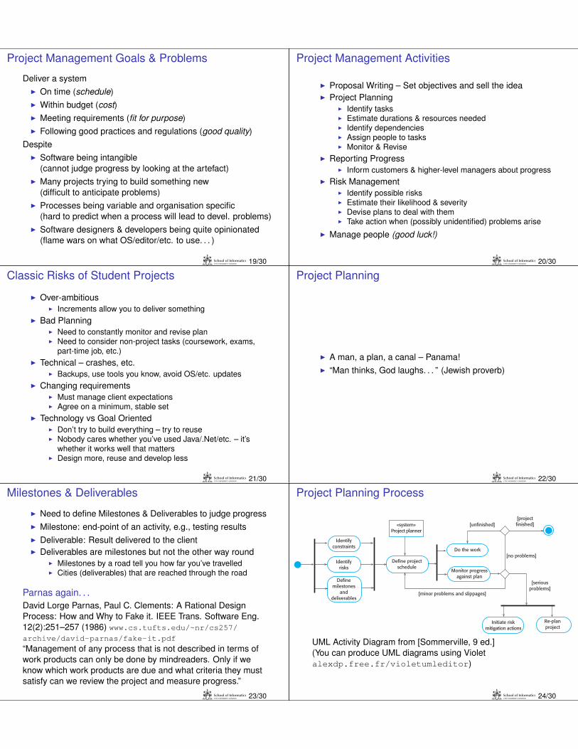
Project Planning Process
The project planning process
Define projectschedule
Identifyrisks
Identifyconstraints
Definemilestones
anddeliverables
«system»Project planner
Do the work
Monitor progressagainst plan
[no problems]
[minor problems and slippages]
[projectfinished][unfinished]
[seriousproblems]
Initiate riskmitigation actions
Re-planproject
UML Activity Diagram from [Sommerville, 9 ed.](You can produce UML diagrams using Violetalexdp.free.fr/violetumleditor)
24/30

Project Scheduling
I Identify tasksI Organise them to run concurrentlyI Minimise dependencies (maybe by decomposing tasks)I Estimate task duration if done by one person (PersonMonths)I Estimate other resourcesI Decide how many resources (people too) to assign to itI Fallacy:
I More workers makes a task finish fasterI Might increase throughput but not decrease response time.
One couple can produce a baby in 9 months.Can 9 couples produce a baby in 1 month?
I Might even delay the task.Too many cooks in the kitchen. . .
25/30
Gantt Charts – House Building
26/30
PERT Charts – House Building
27/30
PERT Charts – The Critical Path
I The critical path can change during the project!I Make sure you know which is the current one!
28/30
Tools – Artisans are Judged by their Tools. . .
I Planning – Gantt/PERT chartsI Gantt Project http://www.ganttproject.biz/
I UML ModellingI Violet alexdp.free.fr/violetumleditor
I Version ManagementI SubversionI CVS
I Build ManagementI MakeI Ant (Java only)I GNU automake/autoconf
I Others: Zotero(?), GNU Emacs(!), Eclipse, OSGiI Languages: Java, C++, Lisp, ProLog, ML/Haskel,
AWK/Perl/Python, Bourne Shell, LATEX, . . .
29/30
Summary
I Waterfall Process – Easy to grasp, difficult to make it workI Documentation is vital – fake the Waterfall if you mustI Incremental
I Increase likelihood that you’ll deliver something valuableI Make it easier to accommodate requirements changesI Watch out for architectural/design degradation! Refactor often!
I Management: Make sure you deliver (without Prozac. . . )I Constant Planning, Risk Management, Reporting
I PlanningI Milestones, DeliverablesI Tasks, Dependencies, ConcurrencyI Control Concurrency – Use it Wisely!I Resource Allocation, SchedulesI Charts – Gantt, PERT, Critical Path
30/30

IN1005 Software EngineeringLecture 3 – Requirements Engineering – Part I
Christos Kloukinas
Department of ComputingCity University London
2010–2011
1/32
Topics Discussed Previously – Dev. ProcessesI Waterfall Process
I Easy to grasp – Difficult to make it workI Good for small projects, where requirements are clear/stableI Risky when requirements are unclear/unstableI Used in large projects to synchronise everyone – risk factor!I Royce wanted a preliminary low-level design and a
prototype system with lots of interactions with the clientI Documentation is vital
I Very difficult to understand choices made/system without itI Need to follow a logical order, not a historical oneI Fake the Waterfall if you must!
I Incremental Development ProcessI Increase likelihood that you’ll deliver something valuableI Make it easier to understand requirements – get
experience with the system through the early incrementsI Make it easier to accommodate requirements changesI Watch out for architectural degradation! Refactor often!
I Reuse-based Development: Negotiate req. changes to max. reuseI Feel free to combine processes if it makes sense
2/32
Topics Discussed Previously – Project Management
I Management: Make sure you deliver (without Prozac. . . )I Constant Planning, Risk Management, Reporting
I PlanningI Milestones, Deliverables (what needs to be achieved)
I Deliverables = MilestonesI Milestones 6= Deliverables
I Tasks (how to achieve it)I Keep tasks short – long tasks hide problemsI Identify task dependenciesI Try to maximise concurrency
Break up tasks to achieve fine-grained dependenciesI Control Concurrency – Use it wisely!
I Resource Allocation, SchedulesI Charts: Gantt, PERT, Critical Path – Use Real Tools!I Monitor the plan every day and re-plan
I Problems don’t arise at milestonesI They arise a day at a time – don’t miss that day. . .
3/32
Table of ContentsRequirements – Introduction
Requirements SourcesRequirements Levels & TypesDomain & Non-functional RequirementsRequirements Properties – The 5 C’s & Their 3 C’sins. . .Verifiability
Specifying RequirementsGeneral GuidelinesSome HelpVolere Shell & Friends to our Rescue
Eliciting RequirementsHow – Questionnaires/InterviewsHow – ScenariosHow – Ethnography
Summary
4/32
What are Requirements?
I Descriptions of What tasks the system must & must not doI Descriptions of the Constraints
I Under which it must do its tasksI Under which it must be developedI Imposed by society and other external factors
5/32
Where do Requirements Come from?
I The application domainI Legal or other regulations, acceptable processes, etc.I What the client, users, etc. state they want
I Problem #1: Stated needs 6= Real needs!!!I Problem #2: Stated needs 6= Total needs!!!I Problem #3: Stated “needs” = Bad solutions!!!
(a.k.a. over-constraining/over-specification)
6/32

The Client is the King NOT!“Whatever the client says must be done!”
I Totally untrueI As an engineer you must identify their real needsI As an engineer you have a duty to society as well
I Cannot break laws and regulations because clients want itI If you cannot convince them, might have to walk away. . .
Better than seeing your face in the papers/causing harm. . .I If SW is hard for SW Engineers to understand and design,
it’s even more difficult for clientsI Often they don’t know what they needI May hide info or even lie for political reasonsI May have strong opinions neverthelessI It’s your professional duty to protect them – & us!
Just like doctors don’t simply do what their patients ask them for.The Client is Your Patient!
And so is Society!7/32
Types of Requirements Levels
I User RequirementsI High-level, imprecise statements in informal languageI The BIG problem!I Toto, I think we’re not in Kansas anymore. . .I Client managers/engineers, users, system architect
I System RequirementsI Structured, precise statements – can be used as a contractI Easier to deal with but are they reflecting real needs?I Are they reflecting all of the real needs?I Client engineers, users, system architect, SW developers
I Software Design SpecificationI Detailed SW description – Basis for design and developmentI Toto, we’re back in Kansas!I System architect, SW developers
8/32
Types of Requirements
I Functional RequirementsI What the system must do and what it must not do
I Non-functional RequirementsI Constraints on how the system should perform its tasks
(within 100 µs, within 64 KB RAM, . . . )I Constraints on the development process
(use Java 1.4.3, have an independent testing team, . . . )I Domain Requirements
I Constraints imposed by the domain of operation.I Can be natural laws or legal obligations/regulations
(financial institutions need to follow certain rules)I The client doesn’t require them – the domain does
9/32
Domain Requirements
I Derived by the application domain, not the usersI Failure to meet one may mean the whole system is unworkable!I Examples
I All databases must have a Z39.50-based user interfaceI The deceleration of a train shall be computed as:
Dtrain = Dcontrol + Dgradient , whereDgradient = 9.81ms2 ∗ compensated gradient/α WHAT?!?!?
I Users may not state them because its second nature tothem (but not to you. . . )
I May have them, yet still have no clue what they meanI Very easy to screw upI Never assume anything about them (especially that you
understand them “more or less”) – keep asking questions!I The whole point behind introducing bioinformatics, financial
computing, etc. degrees – to learn the domain as well.Just like Civil/Electrical/Mechanical/Chemical/etc. Engineering
10/32
Non-Functional Requirements
I Usually relate to a system as a whole – not to a component.What makes a Ferrari fast? Its engine? Body? Wheels?
I Can influence the whole architectureI Can lead to many functional requirements (e.g., security).
Need locks, chains, guards, dogs, cameras, . . .I Failure to meet one may mean the whole system is unusable!I Often are difficult to verifyI Can be classified into
I Product requirementsI Organisational requirementsI External requirements
11/32
Non-Functional Requirements General Classification
I ProductI DependabilityI UsabilityI MaintainabilityI SecurityI E fficiency
I PerformanceI Space
I OrganisationalI OperationalI DevelopmentI Environmental
I ExternalI E thicalI RegulatoryI Legislative
I AccountabilityI Safety/security
[Sommerville, 9th ed.]
I Capturing the requirements is far more important thanclassifying them “correctly”
I Different classifications existI Classification is just an aid
I Is there anything else to do for class A?I What are the test metrics that can be used for class A?
12/32

Properties Requirements Should Have
I Just like all other artifacts, reqs should have some propertiesI When they don’t, the design is difficult/impossible to get rightI And too much time/money is spent on discovering the real
requirements the hard wayI What we need is “The 5 C’s & Their 3 Young C’sins”. . .
13/32
The Five C’s: Clarity, (over-)Constraining,Completeness, Consistency & Correctness
I Requirements should be clearI Avoid ambiguityI Preliminary low-level design to identify unclear requirements
I They should not specify how something is to be achieved.That’s over-constraining the design-space – over-specification
I Watch out for concealed (or not) specifications of solutionsI Try to identify why they want things done that wayI What’s the real problems they’re trying to solve?I Are there better ways to solve them?
I Should be complete – define everything that is requiredI Again, preliminary low-level design – any missing info?
I Should be consistent – no contradictory requirementsI NHS: Government wants A, managers want B, doctors want C,
nurses want D, patients want E , relatives want F , . . .I And you’re in the middle. . . – guess who’s the fall guy?
I Oh, and they should be correct . . .I What is really needed & what we really intend to build
Usually they’re none of the above. . . apart from over-constraining. . .14/32
Example of Over-Constraining
I Consider a car navigation system, e.g., Tom-Tom:“The driver types in his/her destination co-ordinates (street& town name or a postcode or longitude & latitude) and thesystem shall compute the shortest route to there from thecurrent location”
Q What’s wrong with this user-level requirement?1.2.3.4.
15/32
And Here’s The 3 Young C’sins of the 5 C’s:Realism, Traceability & Verifiability
Requirements must be:I Realistic: Possible to achieve within constraints
I “Produce a vehicle that travels faster than light”I “Build a sky-scrapper on a £1,000 budget”
I Traceable: Possible to linkI A system function/design pattern to some requirement.
Why we’ve built something/built it in a particular way?I A requirement to some system functions/design patterns.
Have we built everything we need to?I Crucial for developing tests (is the requirement fully covered?)
I Verifiable: Possible to verify whether the final systemmeets them or not.
I “System shall have a good user interface”I “Responding shall be done within 1 sec for most cases”I “Product shall be error-free” – too difficult to establish
Good tests are the best way to achieve clarity, correctness and(increase) realism
16/32
Unverifiable Versus Verifiable Requirements
I UnverifiableI “The system should be easy to use by medical staff.”I “It should be organized in such a way that user errors are
minimized.”Q Verifiable?
I
I
[Sommerville, 9th ed.]
17/32
Some Metrics for NF-Requirements
I SizeI MbytesI Number of ROM chips
I UsabilityI Training timeI Number of help framesI Task completion time
I PortabilityI Percentage of target-
dependent statementsI Number of target systems
[Sommerville, 9th ed.]
I SpeedI Transactions per secondI User/event response timeI Screen refresh time
I ReliabilityI Mean time to failureI Probability of unavailabilityI Rate of failure occurrenceI Availability
I RobustnessI Time to restart after failureI Percentage of events causing failureI Probability of data corruption on failure
18/32

General Guidelines on Writing RequirementsI Use the same format for all requirementsI Use language consistently
I Use “shall” for mandatory and “should” for desirableI Try to follow the same sentence structure:
FR The X shall/should (not) do Y.The system shall print receipts for items purchased.The voting machine shall print receipts.Printed receipts shall allow voters to verify their vote.
NFR The X-ing shall/should be done with constraint Y.Receipt printing should take less than 2 seconds.Voting shall be anonymous.Computing deceleration shall use Newton’s formula.
I Highlight text at key parts
I State if a req is ENDURING or VOLATILE – the latter will bite you. . .I Be brief – avoid long sentencesI Avoid jargon (esp. computer one)I Eschew obfuscation. . .
19/32
Natural Language Blues
Problems with natural language to be aware ofI Ambiguity
I One statement can be understood in different waysI Over-flexibility
I Many statements/words can say the same thing differently.Voting receipt, ballot, vote, pick, selection, choice, . . .
I Difficult to modulariseI Have to copy-paste a lotI Difficult to keep copies the same
20/32
How to Decrease the Natural Language Problems
I Create a dictionary of termsI Don’t use terms not in the dictionaryI Group/tag them as inputs, outputs, actors, FR, NFR, etc.I Review often to ensure that there are no synonyms.
I Groups/tags mean you don’t have to look at everything
I Parnas (fake it) suggests typing the terms: %term%, @term@, . . .
21/32
Don’t be Stupid, Be a Smartie!I Use your text processor’s reference & macro capabilities
instead of typing the terms themselves, e.g., in LATEX:\dic{\shall be}{shall be}{MUST}\dic{\anonymous}{anonymous}{No names}\dic{\vote}{vote}{A way...\vote \shall \anonymous - see Req\ref{U:Anon-II}\index{NFR!\ref{U:Anon-I}}...\index{Enduring!\ref{U:Anon-I}}...
I Easy to catch undefined terms, change words (vote->ballot),cross-reference, search for all shall/should type reqs, etc.
I Don’t do it by hand – you’re a programmer, so program it!\newcommand{\dic}[3]{% command, expansion, def\newcommand{#1}{#2}\glossary{[#1] #3}}
A program (\dic) creating another program (#1) andusing it (in the \glossary). . .
22/32
Indexing & Defining Terms – Automatically. . .Index:anonymous, 22, 23attention, 23
EnduringReq-V-A-I, 22
NFRPrivacy
Req-V-A-I, 22Req-V-A-I, 22Security
Req-V-A-I, 22
safe, 23secure, 23shall be, 22, 23
vote, 22, 23
Glossary:anonymous No names please.
attention I will say it only once.safe Uninjured. I am safe.
secure Care-free. I feel secure.shall be MUST.
vote A way to express a preference.
Note: The page of a term’sdefinition is indexed in bold.E.g., “attention, 23”
Use as many groups/tags as you can think of when indexing.23/32
The LATEX Terrorist Strikes Again – Why not Word?
I You can use whatever you know & works bestI But Word will be far more difficult to use in this wayI And it’s very difficult to edit documents collaboratively. . .I And keep all different versions. . .
What changed between v. 1.03 & v. 3.45?I It’s like programming – nobody writes programs in WordI Your requirements specification is just another programI So use a programmer-friendly framework (LATEX) instead.
Leave WYSIWYG & mouse-clicking to users.Work like a programmer 1 – be lazy.
I Indeed, for every tool you consider, ask yourself:Can I program/extend it to do what I want?
I No “macro” language (e.g., Emacs) or no code (e.g., gcc)?Walk away – leave it to those who like working hard. . .
1Have I said this again? 24/32

More Help in Writing Requirements – Volere & Co!
I Specify them using the Volere2 template, developed by theAtlantic Systems Guild3
I Developed to help with the cataloguing of requirementsI And to help us not forget their most important characteristicsI We’ll cover it in (excruciating!) detail in the next lectureI Business Use Cases, Product Use Cases, UML Use Case
diagrams
2www.volere.co.uk3www.systemsguild.com 25/32
The Volere Template Shell
Copyright © the Atlantic Systems Guild Limited Volere Template V14 /4
to illustrate how managers can use requirements as input when managing a project.
Testing Requirements Requirements are made testable by adding a fit criterion. This fit criterion is a measurement of the requirement, which makes it possible to determine whether a given solution fits the requirement. If a fit criterion cannot be found for a requirement, then the requirement is either ambiguous or poorly understood. All requirements can be measured, and all should carry a fit criterion. There are examples of fit criteria throughout the Template.
Requirements Shell The requirements shell is a guide to writing each atomic requirement. The components of the shell (also called a “snow card”) are discussed below. This shell can, and should, be automated.
26/32
How Can we Obtain Requirements?
I Questionnaires/Structured interviews – pre-set questionsI Unstructured interviews – no pre-set questionsI Scenarios – consider a case & work it out with themI Ethnography – observe the natives in their natural habitat. . .
27/32
Questionnaires/Interviews
I Usually a mix of structured/unstructuredI Let them talk – learn to listenI Be open-minded – avoid pre-conceived ideas about reqsI Prompt them with an opening question or a req. proposalI Good for understanding what they do and how they might
interact with the systemI Regress to your childhood – keep asking Why?I Not good for understanding domain requirements
I Too difficult to understand special terminology in adiscussion
I They may find it difficult to explain some domain reqs orthing that it’s not worth to
28/32
Scenarios
I Real-life examples of how a system can be usedI A starting state/eventI Identify the normal flow of eventsI Describe exceptions – what can go wrong at each step †
I Identify concurrent activities that may influence this one †
I Describe the state at the end† So as to identify the Use Cases. . .
29/32
Ethnography
I You’re in exotic Userlandia observing the nativesI Identify what are the tasks they performI Identify how they perform the tasksI Identify social & organisational factorsI Identify what they didn’t think to tell youI Identify what they don’t want to tell youI Identify what they don’t realise even themselves
30/32

Summary I
I Requirements: What to do & Constraints on how to do itI Coming from the domain, laws/etc. & the usersI One has to diagnose them – discover the real problemsI Reqs Levels: User Reqs, System Reqs, SW Design Spec.I Reqs Types: Functional, Non-Functional, DomainI FRs: What to do – Met by some componentI NFRs: Constraints on tasks – Met by the whole systemI NFRs: Product (DUMSE), Organisational (ODE), External (ERL)I Reqs Properties: The 5 C’s & Their 3 Cousins. . .
I Clarity, over-Constraining, Completeness, Consistency & CorrectnessI Realism, Traceability, VerifiabilityI Good tests increase clarity, correctness, realism & verifiability
31/32
Summary II
I Metrics for NFRs – ensure they’re verifiableI Specifying Requirements
I Same format, consistent language, “shall”/“should”FR The X shall/should (not) do Y.
NFR The X-ing shall/should be done with constraint Y.I Enduring versus Volatile ReqsI Natural Language Problems: Ambiguous, over-flexible,
difficult to modulariseI Fight back with dictionaries, groups/tags, synonyms 4
I Automate as much as possible:The least you have to do by hand, the better!
I The Volere template can help a lot (see our next episode)I Eliciting Requirements
I Questionnaires/Interviews, Scenarios, Ethnography
4Get WordNet!!! Amazing little tool and free! 32/32

IN1005 Software EngineeringLecture 4 – Requirements Engineering – Part II
Christos Kloukinas
Department of ComputingCity University London
2010–2011
1/33
Topics Discussed Previously I
I Requirements: What to do & Constraints on how to do itI Coming from the domain, laws/etc. & the usersI One has to diagnose them – discover the real problemsI Reqs Levels: User Reqs, System Reqs, SW Design Spec.I Reqs Types: Functional, Non-Functional, DomainI FRs: What to do – Met by some componentI NFRs: Constraints on tasks – Met by the whole systemI NFRs: Product (DUMSE), Organisational (ODE), External (ERL)I Reqs Properties: The 5 C’s & Their 3 Cousins. . .
I Clarity, over-Constraining, Completeness, Consistency & CorrectnessI Realism, Traceability, VerifiabilityI Good tests increase clarity, correctness, realism & verifiability
2/33
Topics Discussed Previously II
I Metrics for NFRs – ensure they’re verifiableI Specifying Requirements
I Same format, consistent language, “shall”/“should”FR The X shall/should (not) do Y.
NFR The X-ing shall/should be done with constraint Y.I Enduring versus Volatile ReqsI Natural Language Problems: Ambiguous, over-flexible,
difficult to modulariseI Fight back with dictionaries, groups/tags, synonyms 1
I Automate as much as possible:The least you have to do by hand, the better! Be lazy!
I The Volere template can help a lot (we’ll see how today)I Eliciting Requirements
I How – Questionnaires/Interviews, Scenarios, Ethnography
1Get WordNet!!! Amazing little tool and free! 3/33
Table of Contents
The Volere Template
What – Requirements Elicitation GoalsActorsScenarios & Use-CasesVolere Template
Specifying Use-Cases
Summary
4/33
The Volere Shell [Volere template ed. 15, Jan 2010]Requirement #: 75 Requirement Type: 9 Event/BUC/PUC #: 7,9Description: The product shall record all the roads that have beentreated.Rationale: To be able to schedule untreated roads and highlightpotential danger.Originator: Arnold Snow – Chief Engineer.Fit Criterion: The recorded treated roads shall agree with thedrivers’ road treatment logs and shall be up to date within 30 min-utes of the completion of the road’s treatment.Customer Satisfaction: 3 Customer Dissatisfaction: 5Dependencies: All requirements using road and
scheduling data.Conflicts: 105
Supporting Material: Work context diagram terms definitions insection 5.History: Created February 31, 2009. Volere
c© Atlantic Systems Guild
I “If a fit criterion cannot be found for a requirement, then therequirement is either ambiguous or poorly understood.”
5/33
Volere – Fit Criteria
I Functional Requirements: Just check the output – receiptprinted, position of vehicle/function computed correctly, etc.
I Non-Functional Requirements: The difficult partI The Volere approach classifies NFR into many sub-typesI Here are some:
I PerformanceI DeviceI PortabilityI Look-and-feelI UsabilityI Training
I AvailabilityI ReliabilityI RecoverabilityI MaintainabilityI SafetyI Security
I They tell you what they specify, how to measure and test them
6/33

Volere NFR: Performance, Device, Portability
I PerformanceSpecifies time to do things, required throughput ratesMeasure using response times or times to undertake an action
(speed), actions per time period (throughput), or numbersof units handled (load)
Test using response timing, load tests, throughput testsI Device
Specifies features, perhaps interactive, of the productMeasure using adherence to specified standards, device features
and attributesTest using observations of the product by independent
assessors, standards compliance rulesI Portability
Specifies platforms that product needs to operate onMeasure using the names and versions of products and operating
systemsTest using usage trials on range of products
7/33
Volere NFR: Look-and-Feel, Usability, TrainingI Look-and-feel
Specifies how end-users will perceive the productMeasure using adherence to specified standards, use of colours,
adoption of designsTest using observations of the product by independent
assessors, standards compliance rulesI Usability
Specifies how people will interact with the productMeasure using task completion times, error-rates, overall
satisfaction, level of feedback needed for trusting that theproduct works correctly 2
Test (with HCI techniques) with usability evaluation, protocolanalysis and cognitive walkthrough techniques
I TrainingSpecifies levels and nature of training to use the productMeasure using training duration and outcomes
Test using training course outcomes
2Think safety-critical systems. . . 8/33
Volere NFR: Availability, Reliability, Recoverability
I AvailabilitySpecifies nature and levels of access to the productMeasure using times when available, % downtime
Test using system-level trials and user experiencesI Reliability
Specifies levels of failure supported in the productMeasure using mean-time between (defined) failures
Test using product reliability trials, customer evidenceI Recoverability
Specifies the repair of the product in case of failureMeasure using time and likelihood to recover
Test using simple maintenance and recovery tasks
9/33
Volere NFR: Maintainability, Safety, Security
I MaintainabilitySpecifies the acceptable levels of product upgradeMeasure using time and resources to maintain
Test using simple maintenance/updating tasksI Safety
Specifies how safe is the productMeasure using number/risk of injuries in total/over time
Test using health and safety compliance techniquesI Security
Specifies levels of illegal access to the productMeasure using specified access functions, and mean-time between
breachesTest using security experts
10/33
Requirements Elicitation Goals
I Identify ActorsI Identify ScenariosI Identify Use-CasesI Identify Relationships among Actors & Use-CasesI Identify Initial Analysis ObjectsI Identify Non-Functional Requirements (AGAIN???)
[Bruegge & Dutoit, 3rd ed, section 4.4]
11/33
AGAIN??? Req. Elicitation and Analysis Process
(A UML Activity Diagram)
12/33

Actors & Roles
I In UML, Actors are Role abstractions. . .I Actors represent persons/other systems interacting with our systemI Actors are always external to the systemI Actors (i.e., Roles)
I Judge, Jury, ExecutionerI Car navigation system, e.g., Tom-Tom:Q Tom-Tom Actors???
13/33
Problems with Actors (Roles)
I 1 Entity can assume N RolesI Manager, Cashier, Salesperson: Polyanna
I This may not always be a good thingI Loan Requestor, Loan Advisor, Loan Approver: Christos CrookI Judge, Jury, Executioner: Judge Dredd
Q What else can be an actor?Consider a system that waters plants each day at 22:00.Who’s the actor that triggers the watering?
14/33
Identifying Actors
I Identify people/systems interacting with the systemI Who/what uses the system? Joe, TFL, . . .I Who installs the system?I Who starts/stops the system?I Who maintains the system?I Who maintains the system’s data?I Which other systems are linked to the system?I Who gets/gives information to the system?I Does anything happen at a specific time point?
I Identify actorsI What roles do these people/systems play in their
interaction? Driver, Road/congestion info server, . . .
[Bruegge & Dutoit, 3rd ed, section 4.4]
15/33
Scenarios & Use-Cases
I A Scenario is an instance of a Use-Case – it shows asingle line of events
I Both are described from the viewpoint of the userI Both are triggered by a Primary Actor. A single one.|PA(scenario/use-case)| = 1
I Secondary Actors may also interact with the system.|SA(scenario/use-case)| ≥ 0
I We use Scenarios to start fleshing out the Use-CasesI Both describe something that happensI Both named using verbs/verb phrases
I PaySalesTax, ComputeRoute, VerifyShoppingList
16/33
Identifying Scenarios/Use-Cases
I Start with a list of actors that interact with the systemI What would some actor want to do with the system?I If state/info is changed, which actor triggers that?I When changes occur, which actors are notified?I Are there external events that affect the system?
What notifies it about them?I Does the system interact with any other systems?I Does the system produce reports?
17/33
Scenario Types
As-is Scenarios describe the current process – used tounderstand a system and validate thisunderstanding with the users.
Visionary Scenarios describe the future process – used tomodel the new system and communicatewith the clients.
Evaluation Scenarios describe the tasks through which thesystem is to be evaluated. Also helps inimproving the definition of thefunctionality required by these scenarios.
Training Scenarios are essentially tutorials that helpintroduce new users to the system,showing them step-by-step instructionsfor performing tasks.
[Bruegge & Dutoit, 3rd ed, section 4.4]
18/33

Use-Cases
I Use-Case: combines all scenarios for a specific system useI Named using verb phrases – should indicate what the primary actor
is trying to accomplish: ReportEmergency, BorrowBookI Actors named with noun phrases: FieldOfficer, StudentI Should clearly determine the system boundary, e.g., indent system
actions to the right or show non-system actions in italicsI Actions phrased in the active voice, so it’s obvious who does themI Should be clear how one action follows another – causalityI Should describe exceptions separatelyI Should not describe the user interface, only the actionsI Should not be too long – max 2/3 pages. Use «include» & «extend»
relationships to keep them short (considered later)
19/33
Use-Case Types
I Business Use-Cases (BUC)I Terms belong to the business domain, NOT the computing oneI Describe business processes – What are the goals & how to do itI Business goals [Volere template ed. 15, Jan 2010]:Service goals Measured by quantifying what it does for the customers of
the businessRevenue goals Measured by revenue, revenue growth, market share over
some time periodLegal goal Conformance to some law/standard
I Product Use-Cases (PUC)I N PUC linked to 1 BUCI Both business & computing terms usedI Describe how the system will help in achieving the business goalsI Identify which parts of a BUC will be automated (part of the system)
and which not (outside the system boundary)
20/33
Example of Business Use-Cases: Road De-icing IBUC Input/Output BUC Summary1 Weather stationtransmits reading.
Weather stationreadings (in)
Record the readings as ofthat weather station.
2 Weather serviceforecasts weather.
District weatherforecast (in)
Record the forecast.
3 Road engineersadvise changedroads.
Changed road(in)
Record new/changed road,check all appropriate weatherstations are attached.
4 Road Engineer-ing installs newweather station.
New weather sta-tion (in)
Record weather station, at-tach it to these roads.
5 Road Engi-neering changesweather station.
Changed weatherstation (in)
Record changes to theweather station.
6 Time to testweather stations.
Failed weatherstation alert (out)
Determine weather stationsnot transmitting for 2 hours,inform Road Engineering offailures.
[Volere template ed. 15, Jan 2010]21/33
Example of Business Use-Cases: Road De-icing IIBUC Input/Output BUC Summary7 Truck depotchanges a truck.
Truck change (in) Record truck changes.
8 Time to detect icyroads.
Road de-icingschedule (out)
Predict the ice state for thenext 2 hours. Assign trucksto roads that will freeze. Is-sue schedule.
9 Truck treats aroad.
Treated road (in) Record the road as beingsafe for the next 3 hours.
10 Truck depot re-ports truck prob-lems.
Truck breakdown(in)Amended grittingschedule (out)
Reassign available trucks topreviously assigned roads.
11 Time to monitorroad treatment.
Untreated roadreminder (out)
Check all scheduled roadshave been treated in the as-signed time, issue remindersfor untreated roads.
[Volere template ed. 15, Jan 2010]22/33
Product Use-Cases – UML Use-Case Diagram
I Each ellipsis is a PUC (systems underlined, people in bold)[Volere template ed. 15, Jan 2010] 23/33
Product Use-Case Specification - IUse-Case: ProduceDeicingSchedule ID: PUC-8.1Brief description: Produces next De-icing Schedule to follow.Primary Actor: TimeSecondary Actors: TruckDepotEngineer, ThermalMappingDatabasePre-conditions: NoneMain Flow:
1. Time signals TruckDepotEngineer for new schedules every 2 hours.2. System uses the current thermal map from the
ThermalMappingDatabase to determine roads most likely to be icy.3. System orders these roads according to how they can be
reached from the TruckDepot.4. The TruckDepotEngineer decreases concurrency according to
how many trucks are available.5. The TruckDepotEngineer selects times for treating each road.Post-conditions: 1. The DeicingSchedule is produced.
Alternative Flows: None.
24/33

Product Use-Case Specification - II
Use-Case: PaySalesTax ID: 1Brief description: Pay Sales Tax to the Tax Authority at the end of thebusiness quarter.Primary Actor: TimeSecondary Actors: TaxAuthorityPre-conditions: NoneMain Flow:
1. Time signals the end of the business quarter.2. The system determines the Sales Tax owed to the Tax Authority.3. The system sends an electronic payment to the Tax Authority.
Post-conditions:1. The Tax Authority receives the correct amount of Sales Tax.
Alternative Flows: None.
I 1 PUC = 1 Scenario? Branching/alternative flows ⇒ more scenarios.
25/33
Pre and Post-Conditions
I Pre-conditions state the constraints that must be true before ause-case. The use-case cannot start without them.¬ FoodIsAvailable ∨ ¬ TimeIsAvailable ⇒ ¬ HaveMeal
I Pre-conditions do not cause a use-case to start, that’s thetriggering condition/event – specified as step 1 of the main flow.BeHungry ` HaveMeal
I Pre-conditions only block a use-case (when they’re false)I Post-conditions state the constraints that must be true after the
use-case – if false, the use-case failed.HaveMeal ⇒ ¬ BeHungry
I If there are no pre-/post-conditions, write “None”I But if no post-condition, then what’s the purpose of the use-case?
Maybe missing something?
26/33
Main Flow
<step number> The <actor/system> <some action>
I Lists the flow of events in a use-caseI Always begins with the primary actor doing an actionI Steps should be:
I ShortI Declarative – say what needs to be done, not howI Ordered according to the time they are performedI Describe interaction among system and actors
I The main flow is the perfect world scenarioI Everything goes as expected and desired – no errors,
deviations, interruptsI Alternatives shown by branching or by listing under
Alternative Flows
27/33
Branching & Repetition Within a Flow: If & For/While
<step number> If <Boolean condition><step number.1> <some action>
Else<step number.2> <some action>
<step number> For <some elements><step number.1> <some action><step number.2> <some action>
<step number> While <condition><step number.1> <some action><step number.2> <some action>
28/33
Branching into Alternative Flows
I Alternative flows capture errors, deviations, interruptsI Alternative flows never return back to the main flowI Examine each main flow step for:
I AlternativesI ExceptionsI Interruptions
I List the names of the alternative flows in the main use-case,then specify them separately
I Don’t overdo it 3 – only document if needed to clarify requirements
3Best advice ever. . . K.I.S.S.!!! 29/33
Finding Exceptions (A.K.A. Intro to Testing. . . )
I Events: Not occurring, too frequent, too infrequent, wrong order, . . .I Actions: Insufficient information, not completing, . . .I Cognitive Exceptions: Slips, mistakes, lack of knowledge/skill, . . .I Other Human Exceptions: Age, size, gender, disability, . . .I Machine Exceptions: Power failures, breakdowns, blockages, . . .I Human-Machine Exceptions: Misinterpret interface, . . .I Machine-Machine Exceptions: Communication failure, scrambled
messages, wrong representations used, . . .
30/33

Alternative Flows Example - IUse-Case: CreateNewCustomerAccount ID: 5Brief description: System creates a new account for the Customer.Primary Actor: CustomerSecondary Actors: NonePre-conditions: NoneMain Flow:
1. Customer selects “create new customer account”.2. While the Customer details are invalid:
2.1 System asks Customer to enter his/her details (email, password,and again password for confirmation).
2.2 System validates the Customer details.
3. System creates a new account for the Customer.Post-conditions:
1. A new account has been created for the Customer.Alternative Flows: InvalidEmailAddress, InvalidPassword, Cancel.
31/33
Alternative Flows Example - IIAlternative Flow: CreateNewCustomerAccount:InvalidEmailAddressID: 5.1Brief description: System informs Customer that they have providedan invalid email.Primary Actor: CustomerSecondary Actors: NonePre-conditions: 1. Customer has provided an invalid email.
Alternative Flow:1. The alternative flow begins after step 2.2 of the main flow.2. System informs Customer that the email provided is invalid.3. System allows Customer to provide a different email.
Post-conditions: NoneI Note name and ID of the alternative flowI Always state how it is triggered:
I After some step of the main flowI At any time during the main flow, e.g., computer crashI Instead of the main flow/flow step, triggered by an actor
32/33
Summary I
I Volere Shell, more NFR sub-types with measures and testsI Requirements Elicitation GoalsI Requirements Elicitation & Analysis ProcessI Actors & How to identify themI Scenarios, Use-Cases & How to identify themI Scenario Types: As-is, Visionary, Evaluation, TrainingI Use-Cases Types: Business (BUC –
Service/Revenue/Legal goals) & Product (PUC)I Intro to UML Use-Case DiagramsI Use-Case specification
I Pre and Post-conditionsI Main flow, Branching/RepetitionI Alternative flowsI Finding exceptions (a.k.a. finding test cases)
33/33

IN1005 Software EngineeringLecture 5 – Requirements Engineering & Use-Cases
Christos Kloukinas
Department of ComputingCity University London
2010–2011
1/40
Topics Discussed Previously I
I Volere Shell, more NFR sub-types with measures and testsI Requirements Elicitation GoalsI Requirements Elicitation & Analysis ProcessI Actors & How to identify themI Scenarios, Use-Cases & How to identify themI Types I:
I As-Is,I To-Be (Visionary),I Testing (Evaluation),I Training
I Types II:I Business (BUC – Service/Revenue/Legal goals)I Product (PUC)
2/40
Topics Discussed Previously II
I Intro to UML Use-Case DiagramsI Use-Case specification
I Pre and Post-conditionsI Main flow, Branching/RepetitionI Alternative flowsI Finding exceptions (a.k.a. finding test cases)
I Quick glimpse into identifying initial analysis objects
3/40
Table of Contents
Initial Analysis Objects
Use-Case Modelling Example
Requirements and Use-Cases
Advanced Use-Case Modelling
Summary
4/40
Identifying Initial Analysis Objects – Heuristics
I Terms that developers/users must clarify to understand a use-caseI Recurring nouns in the use-cases, e.g., Incident, ForecastI Real-world entities tracked by the system, e.g., Truck, RoadSectionI Real-world processes that the system must track, e.g., ScheduleI Use cases, e.g., ProduceDeicingScheduleI Data sources/sinks, e.g., PrinterI Artifacts with which users interact, e.g., ThermalMappingDatabase
Always use application domain terms – Not IT ones.[Bruegge & Dutoit, 3rd ed, section 4.4]
5/40
Initial Analysis Objects: Roles/Actors & Abstraction
I Are your analysis objects instances of something more general?Find the actors (roles)!Fido→ Dog
I There could be an abstraction that describes the concept better.Abstract over the actors!Dog→ Canine
I Many of them could be grouped into the same class.Add a bit more abstraction. . . (IFF it helps – NOT otherwise)Canine, Feline→ Mammal
6/40

Road De-Icing: Business Data Model
I Identify the business objects and entities involved
I Here: A UML Class DiagramI Can also use Entity-Relationship diagrams
7/40
Cross-Checking Analysis Objects
I (Over-flexibility) If a concept appears in N use-cases, thecorresponding objects should be named the same.Check your dictionary often for terms that should be merged!
I (Ambiguity) If two objects are named the same but correspond todifferent concepts, the concepts have to be renamed.Check your dictionary often for terms that should be split!
I Identify the use-cases that create an object.Where are its attributes given values?
I Identify the actors who can access this information.I Identify use-cases that modify and destroy the object.I Identify the (primary) actors who trigger these use-cases.I (K.I.S.S.) Decide whether the object is really needed.
Is there at least one use-case that depends on it?
Identify: Maintain this info – use automatic indexes – be a smarty![Bruegge & Dutoit, 3rd ed, section 4.4]
8/40
Indexed Objects\index{O:Truck!Created In!PUC-3}\index{O:Truck!Created In!PUC-4}\index{O:Truck!Accessed By!A:FieldOfficer}\index{O:Truck!Accessed By!A:RoadEngineer}\index{O:Truck!Modified In!PUC-5}\index{O:Truck!Destroyed In!PUC-7}\index{PUC-3!Triggered By!A:Time}\index{PUC-4!Triggered By!A:FieldOfficer}
I Use Parnas’ typed terms to easily findterms in the index, for example:
I Objects start with “O:”,I Actors with “A:”,I Actions with “X:”, . . .
I Can go further – use different fonts for:
I objects (O:Truck),I actors (A:FieldOfficer),I actions (X:Selects), . . .
Easier to spot visually.
Index:O:Truck
Accessed ByA:FieldOfficer, 9A:RoadEngineer, 9
Created InPUC-3, 9PUC-4, 9
Destroyed InPUC-7, 9
Modified InPUC-5, 9
PUC-3Triggered By
A:Time, 9PUC-4
Triggered ByA:FieldOfficer, 9
9/40
Supermarket Scales System (S3)
I The system shall:I Weigh different types of vegetables and fruitI Print out a price tag with barcodeI Enable an operator to change prices and namesI Have a signal alarm when problems ariseI Record information for the production of sales reports
I We’ll develop a use-case model, that is:I UML Use-Case Diagram, andI Use-Case Specifications.
Material from [Robert Stroud and Clear View Training]c©City University London 2000–2011c©Clear View Training 2008, v. 2.5
10/40
Finding the Actors
I An actor is a role played by something external to the system(human, machine or time) and to whom the system delivers somevalue
I A single human/system can instantiate several different actorsI Actors come in two kinds:
I Primary actors, using system in daily activitiesI Secondary actors, enabling primary actors to use system
11/40
Finding the Use-Cases
I Consider what the system does for the actors
12/40

Use-Case Specifications
I The template to use – a reminder:
Use-Case: UseCaseName ID:Brief description:Primary Actor:Secondary Actors:Pre-conditions: 1. Pre-Condition1
Main Flow:1. Step1 (the Trigger)2. Step2Post-conditions: 1. Post-Condition1
Alternative Flows:
13/40
WeighProduce I
Use-Case: WeighProduce ID: S3-01Brief description: The A:Customer X:Weighs some O:Produce.Primary Actor: A:CustomerSecondary Actors: None
Pre-conditions:1. The O:Scales are X:Switched on.2. The O:Message “Please weigh produce” is
X:Displayed.
Main Flow:
14/40
WeighProduce IIMain Flow:1. A:Customer X:Places O:Vegetables on the O:Scale
2. System X:Displays O:Message “Select vegetable type”
3. A:Customer X:Presses O:Button for O:Vegetable type4. System X:Reads the O:Vegetable type for the O:Button pressed5. System X:Reads O:Weight on the O:Scale
6. System X:Calculates O:Price of O:Vegetables7. System X:Prints a O:PriceTag showing O:Vegetable type,O:Price/kgr, O:Price of O:Vegetables, and O:Barcode
8. System X:Displays O:Message “Please take price tag”
9. A:Customer X:Takes the O:Ticket
10. A:Customer X:Takes O:Vegetables11. System X:Displays O:Message “Please weigh vegetables”
Post-conditions: 1. . . .Alternative Flows: RunOutOfPaper
15/40
WeighProduce III – RunOutOfPaper Alternative Flow
Alternative Flow: WeighProduce:RunOutOfPaperID: S3-01.01Pre-conditions: 1. O:Scales are out of O:Paper
Alternative Flow:7.
7.1 System attempts to X:Print O:PriceTag but has no O:Paper7.2 System X:Sounds a O:Warning at the supermarket control desk7.3 A:Operator X:Restocks O:Paper in O:Printer
Post-conditions: 1. O:Scales have a new roll of O:Paper
16/40
S3 Summary
I A simple example use-caseI System development – a case of building a model of the worldI Use-Case driven approach – basis for developing systemsI Crucial skill for:
I Your studies (and GPA. . . ):I Second year Team ProjectI Final year Individual ProjectI Placement
I Your professional life:I This is the most difficult problem – figure out the
correct problem and solution from a haystack ofunnecessary, incomplete, inaccurate info
I Programming something specific is relatively easy(and cheap. . . )
17/40
Are we There Yet?
I Have we identified all objects/steps correctly in the use-case/alt-flow?
I Why treat messages as objects?
18/40

When to Perform Use-Case Analysis
I Use cases – system behaviour from the viewpoint of oneor more actors.They are the best choice when:
I The system is dominated by functional requirementsI The system has many user types to which it delivers
different functionalityI The system has many interfaces
I Use cases are designed to capture functional requirements.They are a poor choice when:
I The system is dominated by non-functional requirementsI The system has few usersI The system has few interfaces
19/40
Use-Cases, Requirements & Environment
I Use-Cases relate a system’s requirements to its environment
Use cases, requirements & environment
!! Use cases
!! Relate a system’s requirements to its environment
41
Events triggered by system
System behaviour
Properties of the system
Events into system ENVIRONMENT
USE CASES
REQUIREMENTS
20/40
Linking Use-Cases & RequirementsI Links expressed as a UML Class Diagram:
I Each requirement specified at one of three levels:I System-level requirementI Use-Case-level requirementI Action-level requirement
21/40
Use-Cases XXX Requirements
I Use-Cases satisfy RequirementsI A Use-Case satisfies a Requirement when its behaviour
implements the requirement:
PurchaseItemssatisfiesRequirement: The system shall enable operators tomanage the purchase of items from the supermarket
I Requirements Constraint Use-CasesI The requirement is satisfied when system and actors
behave as expressed in the use-case within the constraintsexpressed by the requirement:
Requirement: The system shall enable the completion of95% of customer purchases within 90 seconds of the startof the purchase of the first item.constrainsPurchaseItems
22/40
Actions Realise Requirements
I The requirement is satisfied when the action enables thesystem/actor to undertake the behaviour described in the use case
2 The system reads customer information from club card.FR1 The system shall read a standard club card barcode.
3 While more products are to be purchased.3.1 The operator swipes the product using the barcode reader.
TR1 The operator shall be trained to read the barcode reader.DR1 The system shall have graphical instructions to use the reader.
3.2 The system displays the item name and price.FR2 The system shall have a standard product barcode.FR3 The system shall retrieve product details from the product DB.FR4 The system shall display product name and price on the display.
23/40
Requirements Constrain Actions
I The requirement is satisfied when the system/actor undertakesthe action within the req. constraints
2 The system reads customer information from club card.PR1 The system shall read all barcodes within 0.25 seconds.RR2 The system shall read the code of 9999/10000 of swiped barcodes.
3 While more products are to be purchased.3.1 The operator swipes the product using the barcode reader.3.1 The system displays the item name and price.
RR2 The system shall read the code of 9999/10000 of swiped barcodes.PR2 The system shall read all barcodes within 0.01 seconds.
24/40

Requirements Tracing
I Functional Requirements are captured in a requirements modeland in a use-case model, so we need to relate the two
I There is a many-to-many relationship between reqs and use-cases:I One use-case covers many individual functional requirementsI One functional requirement may be realised by many use-cases
I Hopefully we have CASE support for requirements tracingI If no CASE support, create a Requirements Traceability matrix:
U1 U2 U3 U4R1R2R3R3R5
(good luck if you do it entirely by hand. . . )
25/40
More Relationships
I So far we’ve considered the basicsI But there’s more!
I Actor generalisationI Use-Case generalisationI Use-Case inclusionI Use-Case extension
26/40
Actor Generalisation – Example
I Customer & SalesAgent are verysimilar
I They both interact withListProducts, OrderProducts,AcceptPayment
I SalesAgent also interacts withCalculateCommission
I Our diagram is a mess – can wesimplify it?
27/40
Actor Generalisation
I If N actors interact with a setof use-cases in the same way,then generalise to another actor
I The descendant actors inheritroles and relationships to usecases of the ancestor actor
I Descendant actors can replacethe ancestor anywhere(The Substitutability Principle)
28/40
Generalisation of Use-Cases
I The ancestor use-case mustbe a more general case of oneor more descendant use-cases
I Child use-cases are morespecific forms of their parent
In UML, names of abstract things arealways in italics – see Order aboveand Purchaser in the previous slide.
29/40
«include» Relationship
I The base use-case executes till:include(SomeUseCase)
I Control passes to SomeUseCaseI When SomeUseCase is finished,
control goes back to the baseuse-case
I Note:I Base use-cases are not complete
without the included use casesI Included use-cases may be
complete use-cases, or may justspecify a fragment of behaviourfor inclusion elsewhere
30/40

«include» Example
Use-Case: ChangeEmployeeDetailsID: 1Brief description: The managerchanges the employee details.Primary Actor: ManagerSecondary Actors: NonePre-conditions:
1. Manager is logged on the system
Main Flow:1. include(FindEmployeeDetails)
2. System displays employee details
3. Manager changes employee details
Post-conditions:
1. Employee details are changed
Alternative Flows: None
Use-Case: FindEmployeeDetailsID: 4Brief description: The managerfinds the employee details.Primary Actor: ManagerSecondary Actors: NonePre-conditions:
1. Manager is logged on
Main Flow:1. Manager enters employee’s ID
2. System finds employee details
Post-conditions:
1. System has found the employee
details
Alternative Flows: None31/40
«extend» Relationship
I «extend» adds new behaviour to abase use-case
I The base use-case specifies oneor more extension points
I The «extend» relationship mayspecify which of the extensionpoints it is extending
I The base use-case does notknow if it’s been extended!
32/40
«extend» – Base Use-Case
Use-Case: ReturnBookMain Flow:1. Librarian enters the borrower’s ID
2. System displays borrower details andborrowed books
3. Librarian finds the book to be returnedextension point: overdueBook
4. Librarian returns the bookPost-conditions:
1. Book has been returned
33/40
«extend» – Extension Use-Case
Use-Case: IssueFineBrief description:Segment 1: Librarian records & prints a fine.Primary Actor: LibrarianSecondary Actors: NoneSegment 1 Pre-conditions:
1. The returned book is overdueSegment 1 Main Flow:1. Librarian enters details of the fine
2. System prints a fine
Segment 1 Post-conditions:
1. Fine has been recorded
2. System has printed the fine
I Extension use-cases have extension segmentsI Inserted at the specified extension points of base use-cases
34/40
«extend» – Multiple Extension Points
Use-Case: IssueFineBrief description:Segment 1: Librarian records & prints a fine.Segment 2: Librarian accepts payment for a fine.Primary Actor: LibrarianSecondary Actors: NoneSegment 1 Pre-conditions:1. The returned book is overdue
. . .Segment 2 Pre-conditions:1. A fine is dueSegment 2 Main Flow:1. Librarian accepts payment from the borrower2. Librarian records the payment3. System prints a receiptSegment 2 Post-conditions:1. Fine is recorded as paid2. System has printed a receipt
I Base use-cases must have the same number of extension points35/40
«extend» – Conditional Extensions
I Can add conditions on «extend» relationshipsI Conditions are Boolean expressions (True/False)I Extension performed only when condition is True
36/40
«extend» vs «include»
I For an include use-case, the event that triggers it is described insidethe use-case that includes it, e.g., at step 3 include FindBook.
I For an extend use-case, the even that triggers it is described insidethe extend use-case itself.The extended use-case has no knowledge of the extension.
I So common system functions that can be used in many places,e.g., view a map, specify a filename, etc. should be representedwith include use-cases.
I Behaviour that can happen anytime or whose occurrence can bemore easily described as a trigger, e.g., impose a fine, deal withnetwork failure, etc. should be represented with an extend use-case.
[Bruegge & Dutoit, 3rd ed, section 4.4]
37/40
Heuristics for «extend» and «include» Relationships
I Use «extend» for exceptional, optional, or seldom-occurring behaviour.E.g., the breakdown of a resource, the notification of nearbyresources responding to an unrelated incident, etc.
I Use «include» for behaviour that is shared across ≥ 2 use-cases.I K.I.S.S.!!! Don’t overdo it with extend/include!
A few longer use-cases (e.g., two pages long) are easier tounderstand and review than many short ones (e.g., ten lines long).
[Bruegge & Dutoit, 3rd ed, section 4.4]
38/40
Summary I
I Initial analysis objectsI Heuristics for identifying themI Abstraction into actors/roles and higher-level objectsI Cross-checking with use-cases
I A use-case modelling exampleI Requirements & Use-Cases
I When’s to specify use-cases (FR, many actors/interfaces)I Use-Cases: High-level program, working on environment
events and system/actor actionsI Links among Use-Cases, Requirements, and Actions
39/40
Summary II
I Advanced Use-Case ModellingI Use-Case/Actor generalisationI Use-Case inclusion
I Inclusion pointsI Base knows of inclusion
I Use-Case extensionI Extension pointsI Base does not know of extensions!I Multiple extension segmentsI Conditional extension
40/40

IN1005 Software EngineeringLecture 6 – Activity Diagrams
Christos Kloukinas
Department of ComputingCity University London
2010–2011
1/37
Topics Discussed Previously – I
I Initial analysis objectsI Heuristics for identifying themI Abstraction into actors/roles and higher-level objectsI Cross-checking with use-cases
I A use-case modelling exampleI Requirements & Use-Cases
I When to specify use-cases (FR, many actors/interfaces)I Use-Cases: High-level program, working on environment
events and system/actor actionsI Links among Use-Cases, Requirements, and Actions
2/37
Topics Discussed Previously – II
I Advanced Use-Case ModellingI Use-Case/Actor generalisationI Use-Case inclusion
I Inclusion pointsI Base knows of inclusion
I Use-Case extensionI Extension pointsI Base does not know of extensions!I Multiple extension segmentsI Conditional extension
3/37
Table of Contents
Why-O-Why?Cost of ErrorsConsequences of ErrorsTherefore
Activity DiagramsWhat For?Activity Diagrams – The BasicsActivity Diagrams – How to UseActivity Diagrams – Examples
Summary
4/37
Requirements – Why Spend So Much Time On Them?
(while reading this, visualise a shell-shocked SW Engineer. . . )
“The hardest single part of building a software system isdeciding precisely what to build.No other part of the conceptual work is as difficult asestablishing the detailed technical requirements, including allthe interfaces to people, to machines, and to other softwaresystems.No other part of the work so cripples the resulting system ifdone wrong.No other part is more difficult to rectify later.”
[Fred Brooks “The Mythical Man Month”] 1
1Book available at the library. 5/37
Indeed. . . – Cost of Errors – IRelative cost to fix an error [Barry W. Boehm, 1976 & 1981a,b]:
Figure from[Boehm 1981b, p. 40]Scale is not linear!
6/37

Indeed. . . – Cost of Errors – II
I And these figures are considered conservative!I Added operational costs incurred by errors increase further
the economic impact of leaving errors to be found after thesoftware has become operational.
I Boehm - creator of the COCOMO 2 method:
Boehm 1976 “Software Engineering” IEEE Trans. Computers,25(12), pp. 1226–1241
Boehm 1981a “An Experiment in Small-Scale ApplicationSoftware Engineering” IEEE Trans. Softw. Eng.,7(5), pp. 482–493
Boehm 1981b “Software Engineering Economics”Prentice-Hall, 1981, ISBN 0138221227 (see pp.39–41 3)
2COnstructive COst MOdel: A model for predicting the cost of SW projects.3Book available at the library. 7/37
Requirements Failure – LASI The London Ambulance Service (LAS) Computer Aided Despatch
(CAD) system failed dramatically on October 26th 1992 shortly afterit was introducedI The system could not cope with the load placed on it by normal use;I The response to emergency calls was several hours;I Ambulance communications failed; andI Ambulances were lost from the system.
I A series of errors were made in the procurement, design,implementation, and introduction of the system.
G. Spanoudakis
Some evidence
(ESI-1996-TR95104)
G. Spanoudakis
Failures due to Requirements - The case of LAS
The London Ambulance Service (LAS):• system for receiving incident calls and dispatching ambulances• collapsed on 26 October 1992
8/37
Why did LAS Fail?
I Incorrect ambulance location dataI Ambulance crews couldn’t use mobile data terminalsI Crews failed to notify statusI AVLS 4 didn’t keep track of ambulance location and status
I Increased incident call frequencyI Poor ambulance allocation
I Multiple ambulances to single callsI Lists of current incidents scrolled off operator screenI Large number of exception messages
I Public kept calling when ambulances did not turn up
See also Ian Sommerville’s “The London Ambulance fiasco”presentation http://bit.ly/gFMeYw
4Automatic Vehicle Location Service 9/37
Requirements Engineering Failures [Neil Maiden]
I Failure to talk to users to determine current work practicesor future system requirements
I The requirements specification was not formally signed offI Requirements were not measurableI Did not look at other emergency service CAD systemsI Key stakeholders and technical requirements omittedI Inept requirements prioritisation and negotiation
I Performance requirements over usability requirementsI No stakeholder validation of requirements or user
requirements testing
In other words: Hubris. . .(who brought in her big sister Nemesis to clean up. . . )
10/37
Not the worst. . . The Three Mile Island accidentI A partial
core meltdownin anuclearreactorplant
I Partly because of:I Inadequately trained operatorsI Information overloadI Much of it irrelevant, misleading or incorrectI Improper quality assurance and maintainanceI Lack of communication of important safety information
(traceability. . . )I Poor management
I Pennsylvania came close to becoming uninhabitable. . .I Spooky coincidence: the film “The China Syndrome” had
come out 12 days earlier with a similar storyline. . .11/37
So. . .
I So, that explains why we’re still dealing with requirements!I This far we’ve looked at how to:
I Describe them in a more structured mannerI Group’em, measure ’n’ test’em 5
I Connect them with the use-cases (high-level solutions to FRs)I Describe the main flow of use-cases
I Problem:I Main flow too “IT-like” – numbered steps, if-then-else, while/repeat,
exceptions. . .I Not even standardised. . . – each one does as s/he pleasesI Too sequential
I Business processes are usually drawn as parallel workflows.I So. . . enter activity diagrams!
5You got to know when to hold’em, know when to fold ’em,Know when to walk away and know when to run.
12/37

Activity Diagrams – What For?
I Activity diagrams are used to describe workflows.I Simple workflows can be described textually (as we’ve done).I But complex ones, with concurrent activities, etc. are better
described graphically:I Easier to follow what is going on at a particular point –
which other actions are taking place at the same time.I Plus, easier to understand by non-IT people
13/37
Activity Diagrams for Choreographies
I Activity diagrams allow us to describe the “choreography”for a number of different entities
I “Orchestration” vs “Choreography” 6:I An orchestra has a conductor during the performance.I But dancers are far more independent.I We use orchestrations to control locally how we do
things using other entities.I We use choreographies to specify how interactions of
independent entities should work.I Orchestration: local view – Statecharts (mainly)I Choreography: global view – Activity Diagrams (mainly)
(Sequence diagrams also used for scenarios)
6Use these to impress at dinner parties. Make sure you also mention“web-services”, “cloud-computing”, “Web 3.0”, . . .
14/37
Activity Diagrams: From A to Z. . .
17/02/2011 23:35fig128002.svg
Page 1 of 1file:///Users/kloukin/Desktop/slides/lec6/fig128002.svg
One starts here
And ends here
I A flow (the arrow) needs a “token” to fire.I It removes the token from its source and hands it to its sink.
I A crossed circle ends a single flow.I The concentric circle ends the whole activity.
Easy Peasy. . .
15/37
In Between: Activities, Actions, and Objects
I Activities describe behaviours – may contain activities7/actions/objects.I Actions: “atomic” activities – no more decompositionI Objects: Produced/Consumed by activities/actions
19/02/2011 00:04fig128258.svg
Page 1 of 1file:///Users/kloukin/Desktop/slides/lec6/figs/fig128258.svg
An Activity
An Action
An Object AnotherAction
7BoUML doesn’t allow this. . . Good nevertheless!
16/37
Activity Diagrams: Decisions and Merges19/02/2011 12:06fig128130.svg
Page 1 of 1file:///Users/kloukin/Desktop/slides/lec6/figs/fig128130.svg
Some Activity
No Action
Yes Action
UndecidedAction
Decided?
[UNDECIDED]
[YES]
[NO]
I Flows out of a decision node labelled with their triggering conditionI Only one outgoing flow is allowed to fire – undefined otherwiseI A merge node shows where the decision branches end 8.I Different decision actions do not block there for others to complete.
8 More on this later. . .
17/37
Multitasking: Forks and Joins
19/02/2011 00:04fig134914.svg
Page 1 of 1file:///Users/kloukin/Desktop/slides/lec6/figs/fig134914.svg
Another Activity
Action1
Action2
I A fork node replicates its input token to all its outgoing flows.I Almost like starting as many threads as out-flows.I Transitions leaving fork: degree of concurrencyI A join node waits for all its input flows to give it a token before
allowing the activity to continue.I A join node produces a single token (unless it’s also a fork).
18/37

Later. . . : Here’s a Test!
20/02/2011 08:44fig128514.svg
Page 1 of 1file:///Users/kloukin/Desktop/slides/lec6/figs/fig128514.svg
action1
action2
action3
[FALSE]
[TRUE]
I A join node waits for all its input flows to give it a token beforeallowing the activity to continue.
I What happens here? Do you really understand joins?
19/37
Adding Nesting: Dependencies19/02/2011 11:39fig128258.svg
Page 1 of 1file:///Users/kloukin/Desktop/slides/lec6/figs/fig128258.svg
DoSomethingPartII
DoSomething DoSomethingPartI
I Activity DoSomething is really a nested activity.I Consisting of DoSomethingPartI and DoSomethingPartII
I Dashed arrow shows the dependency.
20/37
Flow Weights: Give me More!
19/02/2011 12:05fig128386.svg
Page 1 of 1file:///Users/kloukin/Desktop/slides/lec6/figs/fig128386.svg
Football Player Form FootballTeam
{weight=11}
I Weights describe the number of tokens required for theworkflow to continue
21/37
Activity Diagrams: Expansion Regions
19/02/2011 13:30fig128642.svg
Page 1 of 1file:///Users/kloukin/Desktop/slides/lec6/figs/fig128642.svg
Specify TripRoute
<<iterative>>
<<parallel>>
Print Itinerary
Book Hotel
Book Flight
I An activity region that executes multiple times.I Can be of type iterative, parallel or stream
Parallel You get all inputs, treat them (possibly) in parallelIterative You get all inputs, treat them in order (if defined)Stream You get an input at a time, treat them as they come
22/37
Assigning Blame: Partitions19/02/2011 11:02fig128002.svg
Page 1 of 1file:///Users/kloukin/Desktop/slides/lec6/figs/fig128002.svg
Accounting Dep Customer
Invoice MakePayment
Send Invoice
I Introduce “swimlanes” that relate actions to their actors.I Identify which actor is responsible for performing an activity.
(Suralan: I.e., know which git to fire!)
23/37
Exceptions19/02/2011 13:41fig128770.svg
Page 1 of 1file:///Users/kloukin/Desktop/slides/lec6/figs/fig128770.svg
Interruptible Activity Region
Cancel Order
Close OrderProcess Order
CancelRequest
I Action CancelRequest has an “accept event action” stereotype.I Its out-flow has an “interrupt” stereotype (the broken arrow label).
24/37
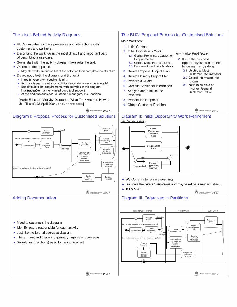
The Ideas Behind Activity Diagrams
I BUCs describe business processes and interactions withcustomers and partners.
I Describing the workflow is the most difficult and important partof describing a use-case.
I Some start with the activity diagram then write the text.I Others do the opposite.
I May start with an outline list of the activities then complete the structure.I Do we need both the diagram and the text?
I Need to keep them synchronised. . .I Activity diagrams: get short activity descriptions – maybe enough?I But difficult to link requirements with activities in the diagram
in a traceable manner – need good tool support!I At the end, the audience (customer, managers, etc.) decides.
[Maria Ericsson “Activity Diagrams: What They Are and How toUse Them”, 22 April 2004, ibm.co/bu3oM5]
25/37
The BUC: Proposal Process for Customised SolutionsMain Workflow:
1. Initial Contact2. Initial Opportunity Work:
2.1 Gather Preliminary CustomerRequirements
2.2 Create Sales Plan (optional)2.3 Perform Opportunity Analysis
3. Create Proposal Project Plan4. Create Delivery Project Plan5. Prepare a Quote6. Compile Additional Information7. Analyse and Finalise the
Proposal8. Present the Proposal9. Obtain Customer Decision
Alternative Workflows:
2. If in 2 the businessopportunity is rejected, thefollowing may be done:2.1 Unable to Meet
Customer Requirements2.2 Critical Information Not
Known2.3 New/Incomplete or
Incorrect GeneralCustomer Profile
26/37
Diagram I: Proposal Process for Customised Solutions19/02/2011 16:00fig128898.svg
Page 1 of 1file:///Users/kloukin/Desktop/slides/lec6/figs/fig128898.svg
CreateProposal Plan
PresentProposal
Obtaincustomerdecision
Compileadditional
information
Createdeilvery project
plan
Communicatewith customer
to obtainmissing
information
Prepare aquote
Analyse andfinalise theproposal
Initial ContactInitial
OpportunityWork
[rejected or redirected to other region or supplier]
[rejected]
[accepted]
[join w. other supplier or change requirements]
SearchAlternatives
27/37
Diagram II: Initial Opportunity Work Refinement19/02/2011 15:59fig140930.svg
Page 1 of 1file:///Users/kloukin/Desktop/slides/lec6/figs/fig140930.svg
GatherPreliminaryCustomer
Reqs
PerformOpportunity
Analysis
Create SalesPlan
Initial Opportunity Work
[if requested]
[else]
I We don’t try to refine everything.I Just give the overall structure and maybe refine a few activities.I K.I.S.S.!!!
28/37
Adding Documentation
I Need to document the diagramI Identify actors responsible for each activityI Just like the tutorial use-case diagramI There: Identified triggering (primary) agents of use-casesI Swimlanes (partitions) used to the same effect
29/37
Diagram III: Organised in Partitions19/02/2011 23:20fig147458.svg
Page 1 of 1file:///Users/kloukin/Desktop/slides/lec6/figs/fig147458.svg
Proposal OwnerCustomer Sales Interface
PresentProposal
Prepare aquote
Obtaincustomerdecision
Communicatewith customer
to obtainmissing
information
Compileadditional
information
Initial Contact
Analyse andfinalise theproposal
Createdeilvery project
planInitialOpportunity
Work
CreateProposal Plan
[rejected]
[accepted]
[rejected or redirected to other region or supplier]
[join w. other supplier or change requirements]
SearchAlternatives
Quote Owner
30/37

Activity Diagrams – Not Just for BUC!
19/02/2011 23:42fig147586.svg
Page 1 of 1file:///Users/kloukin/Desktop/slides/lec6/figs/fig147586.svg
Finishtransaction &print receipt
Prepare toprint receipt
Ask foramount
Verify accesscode
Handleincorrect code
Withdraw money at an ATM.Dispense
cash
[amount unavailable]
[resolved][incorrect]
[unresolved]
[correct]
[amount available]
I Withdrawing money at an ATM – the procedure
31/37
Describing Complex Algorithms – I
UML Superstructure Specification, v2.3 383
The following example shows a use of the shorthand notation for an expansion region with a single action. In this example, the trip route outputs sets of flights and sets of hotels to book. The hotels may be booked independently and in parallel with each other and with booking the flight.
Figure 12.87 - Expansion region
nxteven = lower+upper nxtodd = (lower-upper)*root
lower:Complex upper:Complex
nxteven:Complex nxtodd:Complex
root:Complex
Slower, Supper = cut(S)
«parallel»
S = shuffle(Sneven,Snodd)
Sneven: Array<Complex> Snodd: Array<Complex>
S’: Array<Complex>
S: Array<Complex>
Slower: Array<Complex> Supper: Array<Complex>
V: Array<Complex>
[OMG, “UML . . . ”,fig. 12.87]
32/37
Describing Complex Algorithms - II
“[A] fragment of a Fast Fourier Transform (FFT) computationcontaining an expansion region. Outside the region, there areoperations on arrays of complex numbers. S, Slower, Supper,and V are arrays. Cut and shuffle are operations on arrays.Inside the region, two arithmetic operations are performed onelements of the 3 input arrays, yielding 2 output arrays.Different positions in the arrays do not interact, therefore theregion can be executed in parallel on all positions.”
[OMG, “OMG Unified Modeling Language (OMG UML):Superstructure, Version 2.3”, pp. 382–383] 9
OMG Document Number: formal/2010-05-05URL: www.omg.org/spec/UML/2.3/Superstructure
9The whole ugly truth. . .
33/37
Another Test – Yippie!
UML Superstructure Specification, v2.3 385
Attributes
No additional attributes
Associations
No additional associations
Constraints[1] A final node has no outgoing edges.
Semantics
All tokens offered on incoming edges are accepted. See children of final node for other semantics.
Notation
The notations for final node are illustrated below. There are two kinds of final node: activity final and (IntermediateActivities) flow final. For more details on each of these specializations, see ActivityFinal and FlowFinal.
Examples
The figure below illustrates two kinds of final node: flow final and activity final. In this example, it is assumed that many components can be built and installed before finally delivering the resulting application. Here, the Build Component behavior occurs iteratively for each component. When the last component is built, the end of the building iteration is indicated with a flow final. However, even though all component building has come to an end, other behaviors are still executing. When the last component has been installed, the application is delivered. When Deliver Application has completed, control is passed to an activity final node—indicating that all processing in the activity is terminated.
Rationale
Final nodes are introduced to model where flows end in an activity.
Figure 12.90 - Final node notation
Figure 12.91 - Flow final and activity final example
Activity final Flow final
BuildComponent
[more componentsto be built]
[no more components
InstallComponent
[more componentsto be installed]
[no more components
DeliverApplication
to be built]
to be installed]
[OMG, . . . , fig. 12.91, p. 385]
I Why does the flow end (right crossed circle) when
there are “more components to be installed”?!?I If you don’t understand this, then you don’t understand forks.I Execute the workflow for just 1, and then 2 components.
34/37
Summary – II Importance of Requirements Engineering
I Most difficult part of the conceptual work neededI Most risky part – can cripple the system if done wrongI Error cost up to ≥ 100× if discovered at operation
instead of requirements phase!I Cost of requirements errors:
From leaving people to die to bloody Armageddon. . . 10
I Need to:I Talk to usersI Determine current work practicesI Determine future system requirementsI Have requirements specification formally signed offI Have measurable requirementsI Analyse similar systemsI Involve all stakeholdersI Be careful when prioritising and negotiating – usability matters!I Validate requirements through testing with stakeholders & users.
10No pressure then. . .35/37
Summary – III Activity diagrams: describe complex workflows graphicallyI Can easily describe concurrent activitiesI Mainly used to describe choreographies (i.e., global view)
I How independent entities interact & coordinateI But can also be used for orchestrations (i.e., local view)
I How local activities are organisedI Activity diagrams basic elements:
I Start & end nodesI Activity, action, objectI Decision & merge nodesI Fork & join nodesI Dependencies – Refining activitiesI Flow weightsI Expansion regions: «parallel», «iterative», and «stream»I Partitions, i.e., swimlanes – associate actors to actionsI Exceptions
36/37

Summary – III
I Describing BUC – workflow’s the most important partI Both textually and graphically (keep synchronised!)I Example: Proposal for customised solutions
I General workflow firstI Refine key activities (not all of them!)I Document diagram – partition into swimlanes
I Not just for BUCI Both for simple and complex/parallel procedures
I Ensure you. . .I Know your forksI And your joins
37/37

IN1005 Software EngineeringLecture 7 – Objects & Classes – Part I
Christos Kloukinas
Department of ComputingCity University London
2010–2011
1/29
Topics Discussed Previously – II Importance of Requirements Engineering
I Most difficult part of the conceptual work neededI Most risky part – can cripple the system if done wrongI Error cost up to ≥ 100× if discovered at operation
instead of requirements phase!I Cost of requirements errors:
From leaving people to die to bloody Armageddon. . . 1
I Need to:I Talk to usersI Determine current work practicesI Determine future system requirementsI Have requirements specification formally signed offI Have measurable requirementsI Analyse similar systemsI Involve all stakeholdersI Be careful when prioritising and negotiating – usability matters!I Validate requirements through testing with stakeholders & users.
1No worries. . .2/29
Topics Discussed Previously – III Activity diagrams: describe complex workflows graphicallyI Can easily describe concurrent activitiesI Mainly used to describe choreographies (i.e., global view)
I How independent entities interact & coordinateI But can also be used for orchestrations (i.e., local view)
I How local activities are organisedI Activity diagrams basic elements:
I Start & end nodesI Activity, action, objectI Decision & merge nodesI Fork & join nodesI Dependencies – Refining activitiesI Flow weightsI Expansion regions: «parallel», «iterative», and «stream»I Partitions, i.e., swimlanes – associate actors to actionsI Exceptions
3/29
Topics Discussed Previously – III
I Describing BUC – workflow’s the most important partI Both textually and graphically (keep synchronised!)I Example: Proposal for customised solutions
I General workflow firstI Refine key activities (not all of them!)I Document diagram – partition into swimlanes
I Not just for BUCI Both for simple and complex/parallel procedures
I Ensure you. . .I Know your forksI And your joins
4/29
Table of Contents
Why Object-Orientation?
Objects
Classes
Summary
5/29
From Procedures to Objects
I So far our models and analyses are not object-orientedI Use-cases describe services – can be implemented as
procedures (think of void main(...), Math.sin())I Activity diagrams describe workflows and proceduresI What about objects and object-orientation?I Why do we need them?
WARNING! CODE AHEAD!
6/29
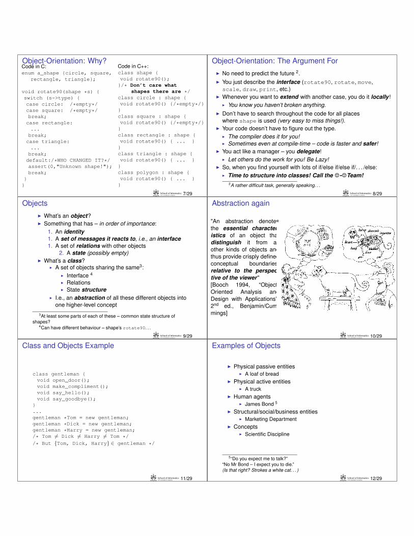
Object-Orientation: Why?Code in C:enum a_shape {circle, square,
rectangle, triangle};
void rotate90(shape *s) {switch (s->type) {case circle: /*empty*/case square: /*empty*/break;case rectangle:...break;case triangle:...break;default:/*WHO CHANGED IT?*/assert(0,"Unknown shape!");break;
}}
Code in C++:class shape {void rotate90();}/* Don’t care what
shapes there are */class circle : shape {void rotate90() {/*empty*/}}class square : shape {void rotate90() {/*empty*/}}class rectangle : shape {void rotate90() { ... }}class triangle : shape {void rotate90() { ... }}class polygon : shape {void rotate90() { ... }}
7/29
Object-Orientation: The Argument ForI No need to predict the future 2.I You just describe the interface (rotate90, rotate, move,scale, draw, print, etc.)
I Whenever you want to extend with another case, you do it locally !I You know you haven’t broken anything.
I Don’t have to search throughout the code for all placeswhere shape is used (very easy to miss things!).
I Your code doesn’t have to figure out the type.I The compiler does it for you!I Sometimes even at compile-time – code is faster and safer!
I You act like a manager – you delegate!I Let others do the work for you! Be Lazy!
I So, when you find yourself with lots of if/else if/else if/. . . /else:I Time to structure into classes! Call the ,-,Team!
2A rather difficult task, generally speaking. . .
8/29
ObjectsI What’s an object?I Something that has – in order of importance:
1. An identity1. A set of messages it reacts to, i.e., an interface1. A set of relations with other objects
2. A state (possibly empty)I What’s a class?
I A set of objects sharing the same3:I Interface 4
I RelationsI State structure
I I.e., an abstraction of all these different objects intoone higher-level concept
3At least some parts of each of these – common state structure ofshapes?
4Can have different behaviour – shape’s rotate90. . .
9/29
Abstraction again
"An abstraction denotesthe essential character-istics of an object thatdistinguish it from allother kinds of objects andthus provide crisply definedconceptual boundaries,relative to the perspec-tive of the viewer"[Booch 1994, “Object-Oriented Analysis andDesign with Applications”,2nd ed., Benjamin/Cum-mings]
!"#$%&'()*+,(-./01&*234(561&7/368/19):.)665.):01;6<3+561)*36/
Software Systems Engineering G. Spanoudakis
Objects: A synthesis of the definitions
Something that
• represents an entity in a problem domain or a software
system
• has an identity which distinguishes it from all the other objects.
• has a state (i.e., a set of properties and relevant values)
• has relations with other objects
• has behaviour
Software Systems Engineering G. Spanoudakis
"An abstraction denotes the
essential characteristics of an
object that distinguish it from
all other kinds of objects and
thus provide crisply defined
conceptual boundaries,
relative to the perspective of
the viewer "
[Booch 1994]
Object Creation through Abstraction
Objects are created by abstracting the characteristics of an
entity which are of interest to the modeller
10/29
Class and Objects Example
class gentleman {void open_door();void make_compliment();void say_hello();void say_goodbye();
}...gentleman *Tom = new gentleman;gentleman *Dick = new gentleman;gentleman *Harry = new gentleman;/* Tom 6= Dick 6= Harry 6= Tom */
/* But {Tom, Dick, Harry} ∈ gentleman */
11/29
Examples of Objects
I Physical passive entitiesI A loaf of bread
I Physical active entitiesI A truck
I Human agentsI James Bond 5
I Structural/social/business entitiesI Marketing Department
I ConceptsI Scientific Discipline
5“Do you expect me to talk?”“No Mr Bond – I expect you to die.”(Is that right? Strokes a white cat. . . )
12/29
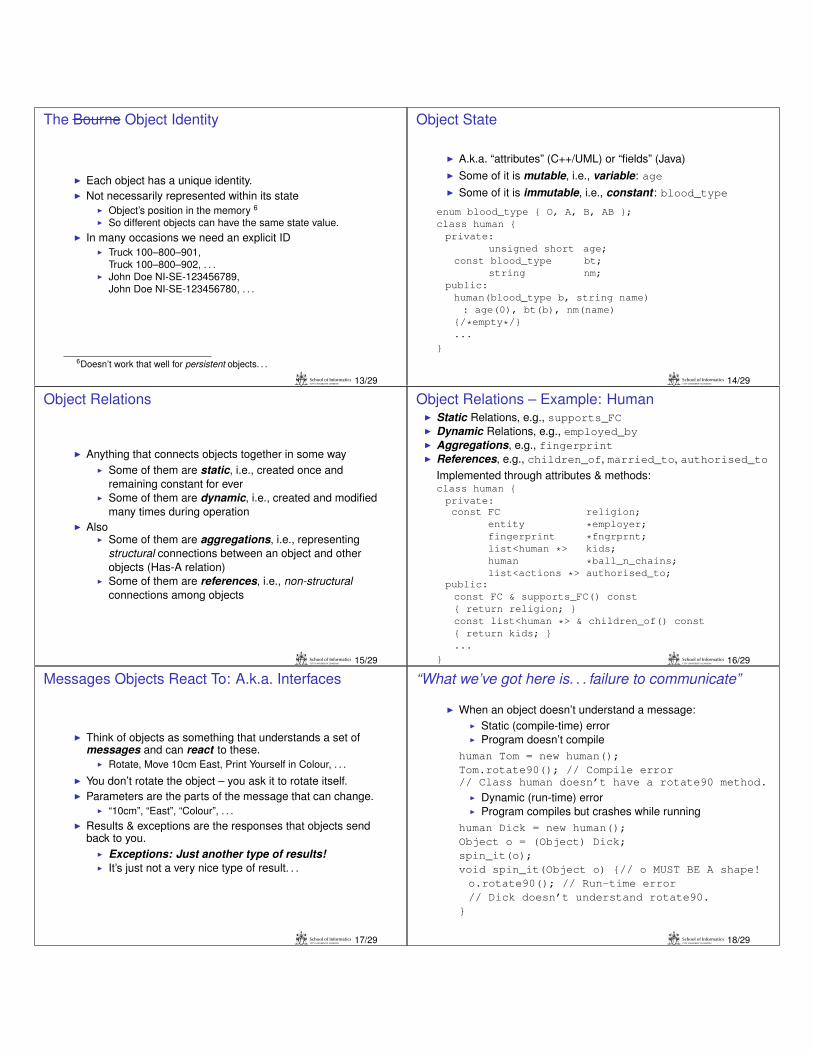
The Bourne Object Identity
I Each object has a unique identity.I Not necessarily represented within its state
I Object’s position in the memory 6
I So different objects can have the same state value.I In many occasions we need an explicit ID
I Truck 100–800–901,Truck 100–800–902, . . .
I John Doe NI-SE-123456789,John Doe NI-SE-123456780, . . .
6Doesn’t work that well for persistent objects. . .
13/29
Object State
I A.k.a. “attributes” (C++/UML) or “fields” (Java)I Some of it is mutable, i.e., variable: ageI Some of it is immutable, i.e., constant : blood_type
enum blood_type { O, A, B, AB };class human {private:
unsigned short age;const blood_type bt;
string nm;public:human(blood_type b, string name): age(0), bt(b), nm(name)
{/*empty*/}...
}
14/29
Object Relations
I Anything that connects objects together in some wayI Some of them are static, i.e., created once and
remaining constant for everI Some of them are dynamic, i.e., created and modified
many times during operationI Also
I Some of them are aggregations, i.e., representingstructural connections between an object and otherobjects (Has-A relation)
I Some of them are references, i.e., non-structuralconnections among objects
15/29
Object Relations – Example: HumanI Static Relations, e.g., supports_FCI Dynamic Relations, e.g., employed_byI Aggregations, e.g., fingerprintI References, e.g., children_of, married_to, authorised_to
Implemented through attributes & methods:class human {private:const FC religion;
entity *employer;fingerprint *fngrprnt;list<human *> kids;human *ball_n_chains;list<actions *> authorised_to;
public:const FC & supports_FC() const{ return religion; }const list<human *> & children_of() const{ return kids; }...
} 16/29
Messages Objects React To: A.k.a. Interfaces
I Think of objects as something that understands a set ofmessages and can react to these.
I Rotate, Move 10cm East, Print Yourself in Colour, . . .I You don’t rotate the object – you ask it to rotate itself.I Parameters are the parts of the message that can change.
I “10cm”, “East”, “Colour”, . . .I Results & exceptions are the responses that objects send
back to you.I Exceptions: Just another type of results!I It’s just not a very nice type of result. . .
17/29
“What we’ve got here is. . . failure to communicate”
I When an object doesn’t understand a message:I Static (compile-time) errorI Program doesn’t compile
human Tom = new human();Tom.rotate90(); // Compile error// Class human doesn’t have a rotate90 method.
I Dynamic (run-time) errorI Program compiles but crashes while running
human Dick = new human();Object o = (Object) Dick;spin_it(o);void spin_it(Object o) {// o MUST BE A shape!o.rotate90(); // Run-time error// Dick doesn’t understand rotate90.
}
18/29

En-capsul-ation
I What’s the big idea?I Hide things (put them in a capsule)
I What things?I State and/or Behaviour
I Why?I To minimise dependencies
among objects/sub-systems/etc.I How?
I By defining interfaces that don’t exposeyour exact state or behaviour.
I And this buys me what?I You can change both your state structure and
your behaviour without your clients noticing.
19/29
Encapsulation – Not Just for State
I How does the bank decide to grant or refuse a loan?I They might give you some hints but not the full process
I They don’t tell you that they check if they’ve got enoughmoney or are at the brink of collapse. . .
I Or that they refuse if you’re “too” old/young/. . .I How does the bank check if a credit card transaction is
authentic?I No info provided!I How does a flat owner decide whom to rent the flat to?
I May refuse to rent to foreign looking people but are notgoing to tell you that (usually).
20/29
Main Class Relations – Is-A
Generalisation (i.e., Abstraction)Identify a common high-level concept toexpress lower-level ones.
Specialisation (i.e., Refinement)Identify a new subcase of a high-level concept.
I An automobile Is-A vehicle:I vehicle Generalises automobileI automobile Specialises vehicle
I An aeroplane Is-A vehicle:I vehicle Generalises aeroplaneI aeroplane Specialises vehicle
I Generalisation/Specialisation – the two facets of Is-A!
21/29
Main Class Relations – Has-A
Containment (i.e., Aggregation) Has-A relation
I A car Has-A driving-wheelI We have shared aggregation (a.k.a. “aggregation”):
I Component may belong to many composites.I When composite is destroyed, component can remain behind
and be used by others.I A person belongs to possibly many families
(as a child, parent, grandparent, etc.).I An engine of a car – can be reused in other cars
when the first car is damaged.I And composite aggregation (a.k.a. “composition”):
I Component belongs to a single composite.I When composite is destroyed, one (normally) destroys
its components tooI Rows of a table, buttons of a window.
22/29
Aggregation vs Composition
I The main difference is the possibilityto belong to many composites(or indeed be independent – aggregation).
I The destruction of the componentupon the destruction of its composite 7
is mostly an implementation,language-specific problem 8
that has very little to do with design!
Few exceptions only (flush message buffers, close downconnections to DB’s, kill threads, . . . )
7In composition: Yes – In aggregation: No.8Got a Garbage-Collector?
23/29
Generalisation, Aggregation, and Composition in UML
27/02/2011 12:38fig128002.svg
Page 1 of 1file:///Users/kloukin/Desktop/slides/lec7/figs/fig128002.svg
Generalisation/Is-A:circle Is-A shapeshape Generalises circlecircle Specialises shape
human
circle
shape
centre_of_gravity
rotate90()
square
familyHas-A
button
window
1..*
<<aggregation>>
*
11..*
<<composition>>
I button belongs to one window only – window has 0 or more buttonsI shape an interface? Dashed arrow, same arrowhead
24/29

General/Special-isation Implies InheritanceI When S inherits from G – S Is-A G:
I G Generalises SI S Specialises G
I A subclass inherits all the properties of the superclassI Should not be used just to inherit the code of the methods
(very bad karma. . . )I A class can specialise multiple super-classes:
27/02/2011 13:14fig128130.svg
Page 1 of 1file:///Users/kloukin/Desktop/slides/lec7/figs/fig128130.svg
Person
IndividualTaxPayer
TaxationSubject
Employee
company
25/29
Polymorphism
I When the user of a method doesn’t know the type of themethod’s object and the method’s behaviour.
I The object can take many (poly) forms (morphs).I doit(shape &s) {s.rotate90(); s.print();}I Is s a circle? A square?
I We don’t care.I In fact, we don’t want to know!I doit does one thing one time and another thing
the next time, depending on what s is.BLISS! ,
26/29
Summary – I
I The idea behind object-orientationI DelegationI Ease the extension with new sub-cases:
I Do so locally, without breaking existing codeI Hide information from the clients – don’t complicate their life
27/29
Summary – III Objects
I Have identity, interface, relations, stateI Physical passive/active entities, Human agents, Social entities,
ConceptsI Identity – Sometimes not modelled directly, just a memory addressI State – Variable/ConstantI Relations – Static/Dynamic and Aggregations/ReferencesI Objects react to messages (their interface)I Method parameters: Parts of the message that can changeI Method result: Response message from the objectI Method exceptions: Another type of result (undesirable)I Failure to understand a message: Static/Dynamic errorI Offer encapsulation
I Allows to hide state and/or behaviourI Minimises dependencies among objects/sub-systems/etc.I Done through interfacesI Can easily change state structure and/or behaviour,
without clients noticing28/29
Summary – IIII Classes
I Have interface, relations, state structure – object abstractionI Main relations: Is-A, Has-AI Is-A: Generalises/Abstracts, Specialises/RefinesI Has-A: Composite Has-A Component
I Shared aggregation: “Aggregation”I Composite aggregation: “Composition”I In aggregation, components can belong to many composites
or even exist on their own (family aggregates humans)I In composition, components cannot belong to many
composites or exist on their own (window composes buttons)I Another “implementation-centric” difference – (AVOID!)I Aggregation: Composite destroyed, Components live onI Composition: Composite destroyed, Components destroyed too
I (Some) UML arrows (see slide 24)I Multiple inheritanceI Polymorphism
29/29

IN1005 Software EngineeringLecture 8 – Objects & Classes – Part II
Christos Kloukinas
Department of ComputingCity University London
2010–2011
1/29
Topics Discussed Previously – I
I The idea behind object-orientationI DelegationI Ease the extension with new sub-cases:
I Do so locally, without breaking existing codeI Hide information from the clients – don’t complicate their life
I The first & most important client is you. . .
2/29
Topics Discussed Previously – III Objects
I Have identity, interface, relations, stateI Physical passive/active entities, Human agents, Social entities,
ConceptsI Identity – Sometimes not modelled directly, just a memory addressI State – Variable/ConstantI Relations – Static/Dynamic and Aggregations/ReferencesI Objects react to messages (their interface)I Method parameters: Parts of the message that can changeI Method result: Response message from the objectI Method exceptions: Another type of result (undesirable)I Failure to understand a message: Static/Dynamic errorI Offer encapsulation
I Allows to hide state and/or behaviourI Minimises dependencies among objects/sub-systems/etc.I Done through interfacesI Can easily change state structure and/or behaviour,
without clients noticing3/29
Topics Discussed Previously – IIII Classes
I Have interface, relations, state structure – object abstractionI Main relations: Is-A, Has-AI Is-A: Generalises/Abstracts, Specialises/RefinesI Has-A: Composite Has-A Component
I Shared aggregation: “Aggregation”I Composite aggregation: “Composition”I In aggregation, components can belong to many composites
or even exist on their own (family aggregates humans)I In composition, components cannot belong to many
composites or exist on their own (window composes buttons)I Another “implementation-centric” difference – (AVOID!)I Aggregation: Composite destroyed, Components live onI Composition: Composite destroyed, Components destroyed too
I (Some) UML arrowsI Multiple inheritanceI Polymorphism
4/29
Table of Contents
Tutorial 7 – A Misconception
Defining Classes – DetailsVisibilityMultiplicityScopeParameter Direction
Class Types: Entity, Boundary & Control
How To Find Classes
Summary
5/29
Can I Have A Create Method In My Class?I First method suggested for PatientRecord was
“create_a_PatientRecord”I But does that really make sense?I An object’s method needs to be called on some object.I Which object is supposed to receive the
“create_a_PatientRecord” message?I The one you want to create?C c = c.create();
I
Another PatientRecord?C c1 = ...; C c2 = c1.create();
I
How do you create new objects of some class C in Java?Don’t confuse constructors with creation methods.Constructors initialise new objects.
6/29

Can I Have a Create Method In My Class? Sure!
I Some classes do have a create method.I But it doesn’t return an object of that class. . .class Bank {Account create_account(name, PIN);
}
I We say that Bank is a factory class.I Can also have a class-scope method that creates objects
of that class. . . (more on this later)
7/29
What Came First – The Chicken Or The Egg?
I Does a Consultation have a Paymentor a Payment have a Consultation?
I They both have the other!I Which is the component and which the composite?
:-(
I Can X exist without a Y?Payment without a Consultation?
I In a composition this answers the question.I In an aggregation? Components can exist independently.
A human doesn’t need to belong to a family.I What looks like a set of things? A human or a family?
That’s the composite; the other is the component.I As you may have noticed, in many cases
we want a bidirectional relation!Given an X find its Y’s & given a Y find its X’s!
8/29
O-O: Encapsulation & Visibility
I We want to hide things (attributes & methods).I Hide them from whom?!?- Everybody! Visibility: private# Everybody but our subclasses! Visibility: protected
˜Everybody outside our package! Visibility: package(sub-packages also have access)
+ Nobody. Visibility: public
PersonDetails- name: string [2 .. *]# address: string [3]
˜ email_address: string [0 .. 1]+ getNIN(): string
9/29
Multiplicity
PersonDetails- name: string [2 .. *]# address: string [3]
˜ email_address: string [0 .. 1]+ getNIN(): string
I Square brackets after the attributes?I These define their multiplicity.I name: 2 or more stringsI email_address: 0 or 1 string, i.e., it can be null
(one may not have an email address or we may not know it)
10/29
Scope: Instance vs ClassI So far, attributes & methods have belonged to objects.
Scope: Instance (class instance = object)I Sometimes we may want them to belong to the class.
Scope: ClassI E.g., used to keep track of the number of objects.
PersonDetails- count: int = 0 // Class scope (underlined)- ID: int // Instance scope+ get_count(): int# increment_count()+ getID(): intPersonDetails p = new PersonDetails;int id = p.getID();int howmany = p.get_count(); // WRONG!int howmany = PersonDetails.get_count(); // OK!
I What’s static void main(String args[]); ?!?
11/29
On “Parameters”. . . Direction Matters!I Test: Method is given two integers, returns min & max.I How? Methods have only one result.
The return value or some exception – never both.Reminder: An exception is just another type of a result.
I Solution: Allow method to change its parameters back!I Parameter direction:in Input – default. Caller provides value.out Output. Method, not the caller, provides value upon
(normal) return.inout Both Input & Output. Caller provides initial value,
method may change it upon (normal) return.in_restaurant(in cash: money, out steak: food
, out fries: food)
I In UML:+ min_max(inout min: int, inout max: int)
Give it two numbers, it’ll return the min in the firstparameter and the max in the second.
12/29

Parameter Direction – In JavaI In UML: + min_max(inout min: int, inout max: int)I In Java?!?public class mm {public static void minmax(int min, int max) {if (min>max) {int tmp = max; max = min; min = tmp;
}System.out.println("min: " +min
+" max: " +max);}public static void main(String args[]){int i = 2, j = 1; minmax(i, j);System.out.println("min: " +i +" max: " +j);
}}
I Is this going to work? What will be printed?Note: Java passes arguments by value (i.e., copies of them).(In C++: minmax(int &min, int &max) – never said this!)
13/29
Do Try This At Home. . .public class minmax {public int v;public minmax(int i) { v = i; }public static void minmax(minmax min, minmax max) {if (min.v>max.v) {int tmp = max.v; max.v = min.v; min.v = tmp;
}System.out.println("min: " +min.v
+" max: " +max.v);}
public static void main(String args[]) {minmax i = new minmax(2), j = new minmax(1);minmax(i, j);System.out.println("min: " +i.v +" max: " +j.v);
}}
14/29
Class Types: Interface ClassesI Symbol: A circle – the perfect shapeI Set of behaviours that one provides or uses.
06/03/2011 17:44an_interface.svg
Page 1 of 1file:///Users/kloukin/Desktop/slides/lec8/lec8/figures/an_interface.svg
an_interface
rotate()
Provides class A implements shape { ...}
Uses ????class cookie_cutter {
}15/29
Class Types: Actor Classes
I When real actors should be tracked, e.g.,:I To adapt the system’s behaviour:
age, fatigue, transfer rate, etc.I To know which real entity has assumed
the role of some actor:Buyer? Buyer who???
I To allocate resources:AmbulanceCrew (location? availability?)
06/03/2011 17:44an_actor.svg
Page 1 of 1file:///Users/kloukin/Desktop/slides/lec8/lec8/figures/an_actor.svg
an_actor
fatigue_level
16/29
Class Types: Entity Classes
I Symbol: Ball on the groundI Maps real entities & activities the system deals with:
Trucks, schedules, consultation, payment, etc.
06/03/2011 17:44an_entity.svg
Page 1 of 1file:///Users/kloukin/Desktop/slides/lec8/lec8/figures/an_entity.svg
an_entity
size
throw_in()
kick()
17/29
Class Types: Boundary Classes
I Symbol: Door-knob (you use it to open the door. . . )I Allow actors (not actor classes!) to interact with the system:
Windows, graphs, etc.
06/03/2011 17:44a_boundary.svg
Page 1 of 1file:///Users/kloukin/Desktop/slides/lec8/lec8/figures/a_boundary.svg
a_boundary
treat_event()
inform_client()
18/29

Class Types: Control Classes
I Symbol: Spinning wheelI Contain the control logic, that links the boundary classes
with the entity classes.
06/03/2011 17:44a_control.svg
Page 1 of 1file:///Users/kloukin/Desktop/slides/lec8/lec8/figures/a_control.svg
a_control
reaction()
19/29
E-B-C and M-V-C 1
I Entity, Boundary, and Control ClassesI Also known as the Model-View-Control Design Pattern
Model/Entity System’s representation of the worldView/Boundary How model is shown externally
and how the actors can interact with the systemControl Links Entity with Boundary
I Changes Model/Entity accordingto inputs from View/Boundary
I Asks View/Boundary to inform actorsof the Model/Entity changes
Q1 Which of the E-B-C is most likely to change?Q2 How are actor classes related to the above?!?
Who cares about their state?
1I know the alphabet. . . just not in alphabetical order. . .
20/29
Source of Classes – Noun/Verb Heuristics
Source Requirements and Use-CasesAnalyse them and search for:
I Nouns/noun phrases; andI Verbs/verb phrases
Noun Candidate for a class or a class attributeVerb Candidate for a class method or a class relation
I Check – do you have the corresponding classes?
I Try to group according to E-B-C type.
21/29
Heuristics for Mapping Words to Model Entities
[Abbot 1983] 2 heuristics for mapping words to model entities:In Words In Model ExamplesCommon noun Class Field officerProper noun Instance AliceDoing verb Operation Creates, submits, selectsBeing verb Inheritance Is a kind of, is one of eitherHaving verb Aggregation Has, consists of, includesModal verb Constraints Must beAdjective Attribute Incident description
[Bruegge & Dutoit, 3rd ed, section 5.4.1, Table 5-1]
2Abbot R. (1983) “Program design by informal English descriptions,”Communications of the ACM, Vol. 26, No. 11. 22/29
Finding Entity Classes
I If you cannot understand the term, it’s probably an entityclass
I Recurring nouns in use-cases, e.g., IncidentI Real world entities the system needs to track, e.g.,
FieldOfficer, Dispatcher, TruckI Real world activities the system needs to track, e.g.,
EmergencyOperationsPlan, DeIcingSchedule
[Bruegge & Dutoit, 3rd ed, section 5.4.1]
23/29
Finding Boundary Classes
I User interface controls needed to initiate the use-case,e.g., EmergencyButton
I Forms needed for entering data, e.g., IncidentReportForm(Don’t describe their format!)
I Notices and messages for responding to users, e.g.,AlertOfficer, AcknowledgementNotice, OutOfPaperWarning
I Actor terminals, when multiple actors are involved in ause-case, e.g., DispatcherStation(These may need different interfaces)
[Bruegge & Dutoit, 3rd ed, section 5.4.2]
24/29

Finding Control Classes
I Identity one control object per actor in the use-case.This is the actor’s proxy – tries to meet its actor’s goals.
I Identify one control object per use-case.Co-ordinates all the actor control objects – tries to imposesome order 3.
Note A control object’s lifespan should be the extent ofa use-case or of a user session.
I Difficult to identify beginning & end of a control object?⇒ Ill-defined use-case pre- and post-conditions.
[Bruegge & Dutoit, 3rd ed, section 5.4.3]
3LAPD. . . 25/29
Issues With Initial Classes
I Cannot find all attributes and methods this way.I Usually leads to a large number of small classes
plus a few King-Kong ones. . .I Is it possible to compose smaller classes together?
I Small boundary classes may be parts of a larger boundary class.I Control classes of different use-cases could be composed.
I Is it possible to break-up monster classes?Classes should be responsible for doing 3–5 things only.
I Avoid premature implementation – for a SatWatch:I Do include: UniversalTime, Location, Timezone
Domain concepts that need to be representedI Don’t include: TimezoneDataBase, GPSLocator, UserLogin
Implementation specific choices
26/29
Summary – I
Tutorial 7
I Creating new objects – usually someone else’s responsibilityI E.g., a Factory object (Bank creates Accounts)I Who’s the composite and who’s the component?
(A fun game for the whole family!)
Class Definition
I Visibility: Private (-), Protected (#), Package (˜), Public (+)I Multiplicity: attribute [A .. B] where A, B ∈ N ∪ {0, ∗}I Scope: Instance (i.e., object) versus Class (“static”)I Parameter Direction: in, out, inout
27/29
Summary – II
Class Types
I Interface, Actor, Entity, Boundary, and ControlI Interface:
I Provided (implemented) &I Used (attributes, parameters/return values/exceptions)
I Actor class: Subtype of Entity ClassI E-B-C: Like Model-View-Control
View/Boundary most likely to change – Model/Entity andControl are the essential part of the application
28/29
Summary – III
Class Identification
I Noun/Verb Heuristics:I Noun: class or attributeI Verb: method or relationI Abbot’s heuristics
I Heuristics for Entity ClassesI Heuristics for Boundary ClassesI Heuristics for Control ClassesI Issues with Initial Classes
29/29
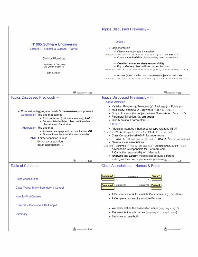
IN1005 Software EngineeringLecture 9 – Objects & Classes – Part III
Christos Kloukinas
Department of ComputingCity University London
2010–2011
1/31
Topics Discussed Previously – I
Tutorial 7
I Object creationI Objects cannot create themselves
AClass anObject = anObject.create(); // NO WAY!!!I Constructors initialise objects – they don’t create them.
I Creation: someone else’s responsibilityI E.g., a Factory object – Bank creates Accounts
Account acc = bank.createAccount(bank, holderName, PIN);
I A class (static) method can create new objects of that classAClass anObject = AClass.create(); // OK - AClass exists
2/31
Topics Discussed Previously – II
I Composition/aggregation – who’s the murderer component?Composition The one that cannot:
I Exist on its own (button of a window); AND †
I Be associated with two objects of the otherclass (button of a window).
Aggregation The one that:I Appears later (payment vs consultation); ORI Does not look like a set (human vs family)
† AND If either condition is false,it’s not a composition,it’s an aggregation. . .
3/31
Topics Discussed Previously – IIIClass Definition
I Visibility: Private (-), Protected (#), Package (˜), Public (+)I Multiplicity: attribute [A .. B] where A, B ∈ N ∪ {0, ∗}I Scope: Instance (i.e., object) versus Class (Java: “static”)I Parameter Direction: in, out, inoutI Java & out/inout parameters. . .Tutorial 8
I (Multiple) Interface Inheritance for type relations (IS-A)Circle IS-A ShapeI, Circle IS-A PrintableI
I Class Composition (HAS-A) for code re-useCircle1 HAS-A 1ShapeImpl, Circle1 HAS-A 1PrintableImpl
I General class associationsDriver1 Drives 1..∗Car, Mechanic1 ResponsibleFor ∗Car
A Mechanic is responsible for 0 or more cars.A Car is the responsibility of 1 Mechanic.
I Analysis and Design models can be quite different,as long as the core properties are preserved.
4/31
Table of Contents
Class Associations
Class Types: Entity, Boundary & Control
How To Find Classes
Example – Consume & Be Happy!
Summary
5/31
Class Associations – Names & Roles13/03/2011 22:03associations-syntax.svg
Page 1 of 1file:///Users/kloukin/Desktop/slides/lec9/lec9/figures/associations-syntax.svg
Person1Company1
Company2 Person2
*
employer
*
employee
employs >
* *
I A Person can work for multiple Companies (e.g., part-time)I A Company can employ multiple Persons
I We either define the association name (employs >), orI The association role names (employer, employee)I Bad style to have both
6/31

Reflexive Class Associations 13/03/2011 21:51reflexive-associations.svg
Page 1 of 1file:///Users/kloukin/Desktop/slides/lec9/lec9/figures/reflexive-associations.svg
FileDirectory
1* *0..1
subdirectory
parent
I A Directory has zero or more FilesI A File belongs to one Directory
I A Directory can have zero or many subdirectoriesI A Directory has zero or one parentI The parent-subdirectory association is reflexive
7/31
Association Classes13/03/2011 22:00association-class.svg
Page 1 of 1file:///Users/kloukin/Desktop/slides/lec9/lec9/figures/association-class.svg
Job
salary
Company3 Person3
**
I A Person can work for multiple Companies (e.g., part-time)I A Company can employ multiple PersonsI Where do we store a Person’s salary?
I Not in Person – different salary for each employeeI Not in Company – different salary for each PersonI It’s a property of the employment association itself
I We need an association class! That’s Job.
8/31
Association Class Reification – Allow MultipleAssociations Among Some Objects
13/03/2011 22:00association-class.svg
Page 1 of 1file:///Users/kloukin/Desktop/slides/lec9/lec9/figures/association-class.svg
Job
salary
Company3 Person3
**
I A Person can have only one Job with some CompanyI What if we want to allow more Jobs with some Company? 13/03/2011 22:22association-class-reified.svg
Page 1 of 1file:///Users/kloukin/Desktop/slides/lec9/lec9/figures/association-class-reified.svg
Company4 Person4Job4
salary1 * * 1
I Now a Person can have multiple Jobs with a CompanyI Job is a reified1 association class. . .1Reify: Consider an abstract concept to be real. [WordNet]
9/31
Class Types: Interface ClassesI Symbol: A circle – the perfect shapeI Set of behaviours that one provides or uses.
06/03/2011 17:44an_interface.svg
Page 1 of 1file:///Users/kloukin/Desktop/slides/lec8/lec8/figures/an_interface.svg
an_interface
rotate()
Provides class Circle implements Shape {...}Uses ????
class CookieCutter {Shape currentShape;Ingredient currentIngredients[];Cookie cutCookie(Shape s, Ingredient i[]);
}Shape, Ingredient, Cookie: interfaces used officially
Unlike Provides, we can use interfaces unofficially(inside the method implementations)
10/31
Class Types: Actor Classes
I When real actors should be tracked, e.g.,:I To adapt the system’s behaviour:
age, fatigue, transfer rate, etc.I To know which real entity has assumed some actor’s role:
Buyer? Buyer who???I To allocate resources:
AmbulanceCrew (location? availability?)
06/03/2011 17:44an_actor.svg
Page 1 of 1file:///Users/kloukin/Desktop/slides/lec8/lec8/figures/an_actor.svg
an_actor
fatigue_level
I Use-Case Actor 6= Actor Class!!!
11/31
Class Types: Entity Classes
I Symbol: Ball on the groundI Maps real entities & activities the system deals with:
Trucks, schedules, consultation, payment, etc.
06/03/2011 17:44an_entity.svg
Page 1 of 1file:///Users/kloukin/Desktop/slides/lec8/lec8/figures/an_entity.svg
an_entity
size
throw_in()
kick()
12/31
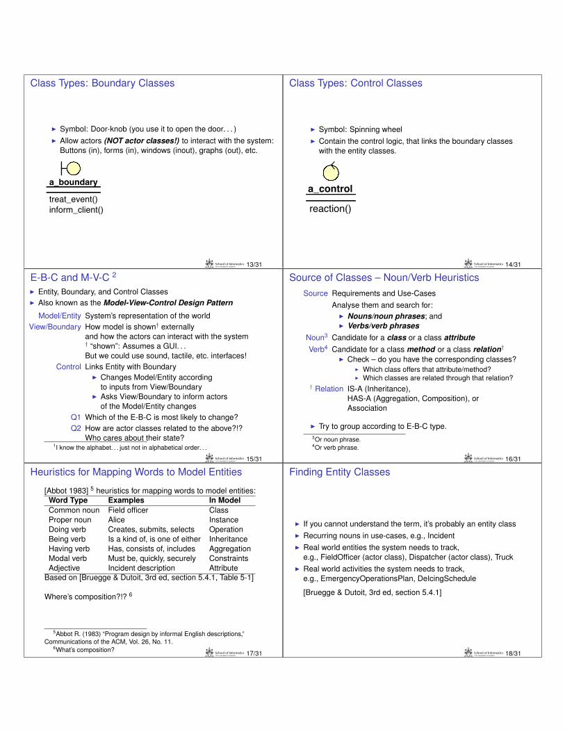
Class Types: Boundary Classes
I Symbol: Door-knob (you use it to open the door. . . )I Allow actors (NOT actor classes!) to interact with the system:
Buttons (in), forms (in), windows (inout), graphs (out), etc.
06/03/2011 17:44a_boundary.svg
Page 1 of 1file:///Users/kloukin/Desktop/slides/lec8/lec8/figures/a_boundary.svg
a_boundary
treat_event()
inform_client()
13/31
Class Types: Control Classes
I Symbol: Spinning wheelI Contain the control logic, that links the boundary classes
with the entity classes.
06/03/2011 17:44a_control.svg
Page 1 of 1file:///Users/kloukin/Desktop/slides/lec8/lec8/figures/a_control.svg
a_control
reaction()
14/31
E-B-C and M-V-C 2
I Entity, Boundary, and Control ClassesI Also known as the Model-View-Control Design Pattern
Model/Entity System’s representation of the worldView/Boundary How model is shown† externally
and how the actors can interact with the system† “shown”: Assumes a GUI. . .But we could use sound, tactile, etc. interfaces!
Control Links Entity with BoundaryI Changes Model/Entity according
to inputs from View/BoundaryI Asks View/Boundary to inform actors
of the Model/Entity changesQ1 Which of the E-B-C is most likely to change?Q2 How are actor classes related to the above?!?
Who cares about their state?1I know the alphabet. . . just not in alphabetical order. . .
15/31
Source of Classes – Noun/Verb HeuristicsSource Requirements and Use-Cases
Analyse them and search for:I Nouns/noun phrases; andI Verbs/verb phrases
Noun3 Candidate for a class or a class attributeVerb4 Candidate for a class method or a class relation†
I Check – do you have the corresponding classes?I Which class offers that attribute/method?I Which classes are related through that relation?
† Relation IS-A (Inheritance),HAS-A (Aggregation, Composition), orAssociation
I Try to group according to E-B-C type.3Or noun phrase.4Or verb phrase.
16/31
Heuristics for Mapping Words to Model Entities
[Abbot 1983] 5 heuristics for mapping words to model entities:Word Type Examples In ModelCommon noun Field officer ClassProper noun Alice InstanceDoing verb Creates, submits, selects OperationBeing verb Is a kind of, is one of either InheritanceHaving verb Has, consists of, includes AggregationModal verb Must be, quickly, securely ConstraintsAdjective Incident description Attribute
Based on [Bruegge & Dutoit, 3rd ed, section 5.4.1, Table 5-1]
Where’s composition?!? 6
5Abbot R. (1983) “Program design by informal English descriptions,”Communications of the ACM, Vol. 26, No. 11.
6What’s composition? 17/31
Finding Entity Classes
I If you cannot understand the term, it’s probably an entity classI Recurring nouns in use-cases, e.g., IncidentI Real world entities the system needs to track,
e.g., FieldOfficer (actor class), Dispatcher (actor class), TruckI Real world activities the system needs to track,
e.g., EmergencyOperationsPlan, DeIcingSchedule
[Bruegge & Dutoit, 3rd ed, section 5.4.1]
18/31

Finding Boundary Classes
I User interface controls needed to initiate the use-case,e.g., EmergencyButton
I Forms needed for entering data, e.g., IncidentReportFormDon’t describe their format!May not be forms at the end – user touches a map location.
I Notices and messages for responding to users, e.g.,AlertOfficer, AcknowledgementNotice, OutOfPaperWarning
I Actor terminals, when multiple actors are involved in ause-case, e.g., DispatcherStation(These may need different interfaces)
[Bruegge & Dutoit, 3rd ed, section 5.4.2]
19/31
Finding Control Classes
I Identity one control object per actor in the use-case.This is the actor’s proxy – tries to meet its actor’s goals.
I Identify one control object per use-case.Co-ordinates all the actor control objects – tries to imposesome order 7.
Note A control object’s lifespan should be the extent ofa use-case or of a user session.
I Difficult to identify beginning & end of a control object?⇒ Ill-defined use-case pre- and post-conditions.
[Bruegge & Dutoit, 3rd ed, section 5.4.3]
7LAPD. . . 20/31
Issues With Initial Interaction Classes
I Cannot find all attributes and methods this way.I Usually leads to a large number of small classes
plus a few King-Kong ones. . .I Is it possible to compose smaller classes together?
I Small boundary classes may be parts of a larger boundary class.I Control classes of different use-cases could be composed.
I Is it possible to break-up monster classes?Classes should be responsible for doing 3–5 things only.
I Avoid premature implementation – for a SatWatch:I Do include: UniversalTime, Location, Timezone
Domain concepts that need to be representedI Don’t include: TimezoneDataBase, GPSLocator, UserLogin
Implementation specific choices
21/31
A Supermarket Self-Checkout Point[Noun/noun phrase] [Verb/verb phrase] . . .
Main Flow:1. A:Customer X:Places O:Vegetables on the O:Scale
2. System X:Displays O:Message “Select vegetable type”
3. A:Customer X:Presses O:Button for O:Vegetable type4. System X:Reads the O:Vegetable type for the O:Button pressed5. System X:Reads O:Weight on the O:Scale
6. System X:Calculates O:Price of O:Vegetables7. System X:Prints a O:PriceTag showing O:Vegetable type,O:Price/Kgr, O:Price of O:Vegetables, and O:Barcode
8. System X:Displays O:Message “Please take price tag”
9. A:Customer X:Takes the O:Ticket
10. A:Customer X:Takes O:Vegetables11. System X:Displays O:Message “Please weigh vegetables”
Post-conditions: 1. . . .Alternative Flows: RunOutOfPaper 22/31
Candidate Classes
I Verbs may indicate control classes or imply relations.I Nouns may indicate actors, boundary classes, entity
classes or relations.
Actor Boundary Control Entity Relation?Class? Class? Class?
Customer Button Checkout Sys. Vegetable Scales -> VegetableDisplay Vegetable Customer -> ButtonScales Type Scales -> DisplayPrinter Price Tag Customer -> Display
23/31
Drawing What We’ve Got – Interaction Classes I 13/03/2011 16:05lecture9-diagrams-v1.svg
Page 1 of 1file:///Users/kloukin/Desktop/slides/lec9/lec9/figures/lecture9-diagrams-v1.svg
Button
Customer CheckoutSystem VegetableType
Scales
Display
Printer
24/31

Fleshing It Out – Adding Attributes & Methods
I Verbs may indicate methods.I Nouns may indicate attributes.
Attribute? Method?Price/Kgr Displays message “Select vegetable type”Price Reads vegetable typeWeight Reads weight on the scalesBarcode Prints a price tag
Displays message “Please take price tag”Displays message “Please weight vegetables”
25/31
Drawing What We’ve Got – Interaction Classes II 13/03/2011 16:34lecture9-diagrams-v2.svg
Page 1 of 1file:///Users/kloukin/Desktop/slides/lec9/lec9/figures/lecture9-diagrams-v2.svg
CustomerVegetableType
name
pricePerKgr
Scales
getWeight()
Display
showMessage()
Printer
printPriceTag()
CheckoutSystem
calculatePrice()
Button
selectVegType()
26/31
Phase II – Splitting/Consolidating
I So far – interaction-based viewI Leads to classes that are not always appropriateI Boundary classes can often be combined into fewer classesI Entity classes often become attributesI Control classes found in each use-case
often combined across use-casesI Need to focus on important business abstractions
instead of E-B-C classes
27/31
Drawing What We’ve Got – Analysis Classes13/03/2011 16:49lecture9-diagrams-v3.svg
Page 1 of 1file:///Users/kloukin/Desktop/slides/lec9/lec9/figures/lecture9-diagrams-v3.svg
Display
showMessage()
CheckoutScales
selectVegetable()
calculatePrice()
generateBarcode()
weighVegetables()
Printer
printPriceTag()
VegetableType
name
pricePerKgr*
1
1
1
1
1
28/31
Summary – IObject Creation
I Not done by the object itself (it doesn’t exist yet)I Either by some other class’ object or the class itself (static)
Component
I The one that’s not the composite. . .
Inheritance
I Type Relation (IS-A) vs Code Reuse (HAS-A)I Inheriting from a class combines bothI Inheriting from an interface and composing with an
implementation class separates them
Associations
I General class relations29/31
Summary – II
Class Types
I Interface, Actor, Entity, Boundary, and ControlI Interface:
I Provided (implemented) &I Used (attributes, parameters/return values/exceptions)
I Actor class: Subtype of Entity ClassI E-B-C: Like Model-View-Control
View/Boundary most likely to change – Model/Entity andControl are the essential part of the application
30/31

Summary – III
Class Identification
I Noun/Verb Heuristics:I Noun: class or attributeI Verb: method or relationI Abbot’s heuristics
I Heuristics for Entity ClassesI Heuristics for Boundary ClassesI Heuristics for Control ClassesI From Initial Interaction Classes to Analysis Classes
31/31
IN1005 Software EngineeringLecture 10 – Revision
Christos Kloukinas
Department of ComputingCity University London
2010–2011
1/30
Table of Contents
Exam Structure & Strategy
Revision Sources & Strategy
The Summaries
2/30
Exam Structure
I Two sectionsSection A
I Weight: 40%I 20 multiple choice questionsI You should answer all of them.
Section B
I Weight: 60%I 2 questions requiring you to specify something.I You should answer one of them.
3/30
Section A – 40%
I 20 Multiple choice questions – 4 choices for eachI Mainly testing your knowledge of definitions.I Some of the questions can be a bit tricky.
Read them (and the answer choices!) carefully.I Marking:
Correct Answer 2.0 MarksNo Answer 0.0 Marks
Incorrect Answer -0.5 MarksI No idea what the answer should be? Better leave it blank.I Section A overall mark:
I Will not be negative even if you get everything wrong.I You can still get full marks from Section B.
4/30
Section B – 60%I DO NOT ANSWER BOTH QUESTIONS IN SECTION B!I Read both of them carefully.I Choose the one that you think you can answer better.I If you do answer both:
I We’ll simply consider the first one you’ve started answering.Even if it’s only a few lines of doodles.
I We’ll totally ignore the other.Even if it’s perfect.
I Don’t want the first one to be considered?Cross it out.
I Answering both usually leads to a lot fewer marks. . .I You’ll be asked to specify something in UML, i.e.,:
I Use-Case DiagramI Activity DiagramI Class Diagram
I Should spend at least 60% of your time on Section B.5/30
Exam Strategy
I Read the whole exam carefully.I Identify parts that you are unsure what they mean.I Ask invigilators for clarifications.I Start answering the questions you understand while you
wait for clarifications on the others.I Start with Section A.I Start with Section A! Get the “easy” marks first.I That way you can then concentrate on Section B without
worrying too much about time.I Choose one question from Section B.I DO NOT ANSWER BOTH QUESTIONS IN SECTION B!I You waste your time and don’t maximise your marks.
6/30

Revision Sources – Handouts
I Go through the “Summary” part of a lecture’s handouts.I Go through the “Topics Covered Previously” in the next lecture.I These give you the main points of a lecture.I Now go through the main part of the handouts and
try to understand each of the main points.I Learn the definitions.I Understand the definitions.I Strange term? Unsure what X means? ASK!I If A looks like B, try to understand their differences!I If A can be used instead of B, try to understand their differences!I Learn when A can be applied and when it cannot be applied.I Not enough to learn the definitions by heart. . .
7/30
Revision Sources – Tutorials
I Try to work them out on your own, without looking at the solutions.I Try to work them out on your own, without looking at the solutions.I Try to work them out on your own,
without looking at the solutions! 1
I Now compare with the solutions andtry to understand why your answers differ (if they do).
I Are your answers wrong?I Are they simply a different way of achieving the same result?I Are they a lot less detailed? (Missed something? Why?)I Are they a lot more detailed? (Problem – Ask)I Are things related differently? (BIG PROBLEM – ASK!)
1You think you understand them and can do them but you don’t.
8/30
Revision Sources – Coursework
I Go through your coursework and the model answers andtry to understand why they differ.
I Coursework model answers to be discussed in Tutorial 10.I Be there.I Be there on time.I Ask questions.I Take notes.
9/30
Revision Strategy
I “Try to understand” – Got Questions?I Post on Moodle!!!I Register to receive all posts by email (there’s a delay. . . ).I Read all posts by others.
Won’t answer if already answered the same question.I Try to answer the questions of others.
Best way to know if you really understand something!I I’ll be posting too – but I’ll be waiting till someone else posts first.
That way I’ll get at least two birds with one stone. . .I Don’t leave it for too late.
May not be reading posts a few days before the exam.
10/30
Lecture 1 – Introduction
I What is Software, Engineering?I Programmer vs SW Engineer, SW vs X Engineering?I What are the Goals of a SW Engineer?
I Dependability Attributes, Threats, MeansI Dependability links with Usability, Maintainability & Efficiency
I How can we Design a SW System?I Data-DrivenI Function-DrivenI Object-Oriented Approaches
I What are our Design Techniques?I ModularityI LocalisationI EncapsulationI AbstractionI Uniformity
11/30
Lecture 2 – Dev. ProcessesI Waterfall Process
I Easy to grasp – Difficult to make it workI Good for small projects, where requirements are clear/stableI Risky when requirements are unclear/unstableI Used in large projects to synchronise everyone – risk factor!I Royce wanted a preliminary low-level design and a
prototype system with lots of interactions with the clientI Incremental Development Process
I Increase likelihood that you’ll deliver something valuableI Make it easier to understand requirements – get
experience with the system through the early incrementsI Make it easier to accommodate requirements changesI Watch out for architectural degradation! Refactor often!
I Reuse-based Development: Negotiate req. changes to max. reuseI Feel free to combine processes if it makes senseI Documentation is vital
I Very difficult to understand choices made/system without itI Need to follow a logical order, not a historical oneI Fake the Waterfall if you must!
12/30
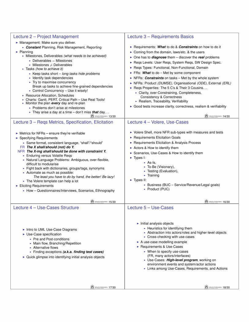
Lecture 2 – Project ManagementI Management: Make sure you deliver.
I Constant Planning, Risk Management, ReportingI Planning
I Milestones, Deliverables (what needs to be achieved)I Deliverables = MilestonesI Milestones 6= Deliverables
I Tasks (how to achieve it)I Keep tasks short – long tasks hide problemsI Identify task dependenciesI Try to maximise concurrency
Break up tasks to achieve fine-grained dependenciesI Control Concurrency – Use it wisely!
I Resource Allocation, SchedulesI Charts: Gantt, PERT, Critical Path – Use Real Tools!I Monitor the plan every day and re-plan
I Problems don’t arise at milestonesI They arise a day at a time – don’t miss that day. . .
13/30
Lecture 3 – Requirements Basics
I Requirements: What to do & Constraints on how to do itI Coming from the domain, laws/etc. & the usersI One has to diagnose them – discover the real problemsI Reqs Levels: User Reqs, System Reqs, SW Design Spec.I Reqs Types: Functional, Non-Functional, DomainI FRs: What to do – Met by some componentI NFRs: Constraints on tasks – Met by the whole systemI NFRs: Product (DUMSE), Organisational (ODE), External (ERL)I Reqs Properties: The 5 C’s & Their 3 Cousins. . .
I Clarity, over-Constraining, Completeness,Consistency & Correctness
I Realism, Traceability, VerifiabilityI Good tests increase clarity, correctness, realism & verifiability
14/30
Lecture 3 – Reqs Metrics, Specification, Elicitation
I Metrics for NFRs – ensure they’re verifiableI Specifying Requirements
I Same format, consistent language, “shall”/“should”FR The X shall/should (not) do Y.
NFR The X-ing shall/should be done with constraint Y.I Enduring versus Volatile ReqsI Natural Language Problems: Ambiguous, over-flexible,
difficult to modulariseI Fight back with dictionaries, groups/tags, synonymsI Automate as much as possible:
The least you have to do by hand, the better! Be lazy!I The Volere template can help a lot
I Eliciting RequirementsI How – Questionnaires/Interviews, Scenarios, Ethnography
15/30
Lecture 4 – Volere, Use-Cases
I Volere Shell, more NFR sub-types with measures and testsI Requirements Elicitation GoalsI Requirements Elicitation & Analysis ProcessI Actors & How to identify themI Scenarios, Use-Cases & How to identify themI Types I:
I As-Is,I To-Be (Visionary),I Testing (Evaluation),I Training
I Types II:I Business (BUC – Service/Revenue/Legal goals)I Product (PUC)
16/30
Lecture 4 – Use-Cases Structure
I Intro to UML Use-Case DiagramsI Use-Case specification
I Pre and Post-conditionsI Main flow, Branching/RepetitionI Alternative flowsI Finding exceptions (a.k.a. finding test cases)
I Quick glimpse into identifying initial analysis objects
17/30
Lecture 5 – Use-Cases
I Initial analysis objectsI Heuristics for identifying themI Abstraction into actors/roles and higher-level objectsI Cross-checking with use-cases
I A use-case modelling exampleI Requirements & Use-Cases
I When to specify use-cases(FR, many actors/interfaces)
I Use-Cases: High-level program, working onenvironment events and system/actor actions
I Links among Use-Cases, Requirements, and Actions
18/30

Lecture 5 – Advanced Use-Cases
I Advanced Use-Case ModellingI Use-Case/Actor generalisationI Use-Case inclusion
I Inclusion pointsI Base knows of inclusion
I Use-Case extensionI Extension pointsI Base does not know of extensions!I Multiple extension segmentsI Conditional extension
19/30
Lecture 6 – Importance of Requirements EngineeringI Importance of Requirements Engineering
I Most difficult part of the conceptual work neededI Most risky part – can cripple the system if done wrongI Error cost up to ≥ 100× if discovered at operation
instead of requirements phase!I Cost of requirements errors:
From leaving people to die to bloody Armageddon. . .I Need to:
I Talk to usersI Determine current work practicesI Determine future system requirementsI Have requirements specification formally signed offI Have measurable requirementsI Analyse similar systemsI Involve all stakeholdersI Be careful when prioritising and negotiating – usability matters!I Validate requirements through testing with stakeholders & users.
20/30
Lecture 6 – Activity DiagramsI Activity diagrams: describe complex workflows graphicallyI Can easily describe concurrent activitiesI Mainly used to describe choreographies (i.e., global view)
I How independent entities interact & coordinateI But can also be used for orchestrations (i.e., local view)
I How local activities are organisedI Activity diagrams basic elements:
I Start & end nodesI Activity, action, objectI Decision & merge nodesI Fork & join nodesI Dependencies – Refining activitiesI Flow weightsI Expansion regions: «parallel», «iterative», and «stream»I Partitions, i.e., swimlanes – associate actors to actionsI Exceptions
21/30
Lecture 6 – Uses of Activity Diagrams
I Describing BUC – workflow’s the most important partI Both textually and graphically (keep synchronised!)I Example: Proposal for customised solutions
I General workflow firstI Refine key activities (not all of them!)I Document diagram – partition into swimlanes
I Not just for BUCI Both for simple and complex/parallel procedures
I Ensure you. . .I Know your forksI And your joins
22/30
Lecture 7 – Why O-O?
I The idea behind object-orientationI DelegationI Ease the extension with new sub-cases:
I Do so locally, without breaking existing codeI Hide information from the clients – don’t complicate their life
I The first & most important client is you. . .
23/30
Lecture 7 – Intro to ObjectsI Objects
I Have identity, interface, relations, stateI Physical passive/active entities, Human agents, Social entities,
ConceptsI Identity – Sometimes not modelled directly, just a memory addressI State – Variable/ConstantI Relations – Static/Dynamic and Aggregations/ReferencesI Objects react to messages (their interface)I Method parameters: Parts of the message that can changeI Method result: Response message from the objectI Method exceptions: Another type of result (undesirable)I Failure to understand a message: Static/Dynamic errorI Offer encapsulation
I Allows to hide state and/or behaviourI Minimises dependencies among objects/sub-systems/etc.I Done through interfacesI Can easily change state structure and/or behaviour,
without clients noticing24/30

Lecture 7 – Intro to ClassesI Classes
I Have interface, relations, state structure – object abstractionI Main relations: Is-A, Has-AI Is-A: Generalises/Abstracts, Specialises/RefinesI Has-A: Composite Has-A Component
I Shared aggregation: “Aggregation”I Composite aggregation: “Composition”I In aggregation, components can belong to many composites
or even exist on their own (family aggregates humans)I In composition, components cannot belong to many
composites or exist on their own (window composes buttons)I Another “implementation-centric” difference – (AVOID!)I Aggregation: Composite destroyed, Components live onI Composition: Composite destroyed, Components destroyed too
I (Some) UML arrowsI Multiple inheritanceI Polymorphism
25/30
Lecture 8 – Object Creation
I Objects cannot create themselvesAClass anObject = anObject.create(); // NO WAY!!!
I Constructors initialise objects – they don’t create them.
I Creation: someone else’s responsibilityI E.g., a Factory object – Bank creates Accounts
Account acc = bank.createAccount(bank, holderName, PIN);
I A class (static) method can create new objects of that classAClass anObject = AClass.create(); // OK - AClass exists
26/30
Lecture 8 – Aggregation vs Composition
I Composition/aggregation – who’s the component?Composition The one that cannot:
I Exist on its own (button of a window);AND †
I Be associated with two objects of theother class (button of a window).
Aggregation The one that:I Appears later (payment vs consultation);
ORI Does not look like a set
(human vs family)† AND If either condition is false,
it’s not a composition,it’s an aggregation. . .
27/30
Lecture 8 – Class Definition, . . .I Visibility: Private (-), Protected (#), Package (˜), Public (+)I Multiplicity: attribute [A .. B] where A, B ∈ N ∪ {0, ∗}I Scope: Instance (i.e., object) versus Class (Java: “static”)I Parameter Direction: in, out, inoutI Java & out/inout parameters. . .
Plus
I (Multiple) Interface Inheritance for type relations (IS-A)Circle IS-A ShapeI, Circle IS-A PrintableI
I Class Composition (HAS-A) for code re-useCircle1 HAS-A 1ShapeImpl, Circle1 HAS-A 1PrintableImpl
I General class associationsDriver1 Drives 1..∗Car, Mechanic1 ResponsibleFor ∗Car
A Mechanic is responsible for 0 or more cars.A Car is the responsibility of 1 Mechanic.
I Analysis and Design models can be quite different,as long as the core properties are preserved.
28/30
Lecture 9 – Class Types, Identification, Associations
I Interface, Actor, Entity, Boundary, and ControlI Interface:
I Provided (implemented) &I Used (attributes, parameters/return values/exceptions)
I Actor class: Subtype of Entity ClassI E-B-C: Like Model-View-Control
View/Boundary most likely to change – Model/Entity andControl are the essential part of the application
29/30
Lecture 9 – Class Identification, Associations, Etc.
Class IdentificationI Noun/Verb Heuristics:
I Noun: class or attributeI Verb: method or relationI Abbot’s heuristics
I Heuristics for Entity/Boundary/Control ClassesI From Initial Interaction Classes to Analysis Classes
Associations, etc. (Tutorial 9)I Reflexive AssociationsI Association ClassesI Reified Association ClassesI Class diagrams cannot express all constraints, so. . .I We add OCL constraints (not to be examined)
30/30