some aspects of the failure mechanisms in batio 3-based ... · pdf filemarch 26-29, 2012 carts...
TRANSCRIPT

March 26-29 2012 CARTS International Las Vegas NV
59
Some Aspects of the Failure Mechanisms in BaTiO3-Based Multilayer Ceramic Capacitors
David (Donhang) Liu MEI Technologies Inc NASA Goddard Space Flight Center Greenbelt MD 20771 Donhangliu-1nasagov
Michael J Sampson NASA Goddard Space Flight Center Greenbelt MD 20771 MichaelJSampsonnasagov
Abstract
The objective of this presentation is to gain insight into possible failure mechanisms in BaTiO3-based ceramic capacitors that may be associated with the reliability degradation that accompanies a reduction in dielectric thickness as reported by Intel Corporation in 2010 The volumetric efficiency (microFcm3) of a multilayer ceramic capacitor (MLCC) has been shown to not increase limitlessly due to the grain size effect on the dielectric constant of ferroelectric ceramic BaTiO3 material The reliability of an MLCC has been discussed with respect to its structure The MLCCs with higher numbers of dielectric layers will pose more challenges for the reliability of dielectric material which is the case for most base-metal-electrode (BME) capacitors
A number of MLCCs manufactured using both precious-metal-electrode (PME) and BME technology with 25 V rating and various chip sizes and capacitances were tested at accelerated stress levels Most of these MLCCs had a failure behavior with two mixed failure modes the well-known rapid dielectric wearout and so-called ldquoearly failuresrdquo The two failure modes can be distinguished when the testing data were presented and normalized at use-level using a 2-parameter Weibull plot The early failures had a slope parameter of β gt1 indicating that the early failures are not infant mortalities
Early failures are triggered due to external electrical overstress and become dominant as dielectric layer thickness decreases accompanied by a dramatic reduction in reliability This indicates that early failures are the main cause of the reliability degradation in MLCCs as dielectric layer thickness decreases All of the early failures are characterized by an avalanche-like breakdown leakage current The failures have been attributed to the extrinsic minor construction defects introduced during fabrication of the capacitors
A reliability model including dielectric thickness and extrinsic defect feature size is proposed in this presentation The model can be used to explain the Intel-reported reliability degradation in MLCCs with respect to the reduction of dielectric thickness It can also be used to estimate the reliability of a MLCC based on its construction and microstructure parameters such as dielectric thickness average grain size and number of dielectric layers
Measures for preventing early failures are also discussed in this document
Introduction
An inevitable trend in the miniaturization of MLCCs is an attempt to increase the capacitance volumetric efficiency (microFcm3) A typical monolithic MLCC structure is shown in Figure 1 A number of dielectric layers and internal electrodes are alternately stacked up together and the internal electrodes are connected in parallel to form end terminations for the electrical contacts The capacitance 119862119905 of an MLCC can be represented by
119862119905 = 1205760 ∙ 120576119903 ∙ 119873 ∙119878119889
(1)
httpsntrsnasagovsearchjspR=20120009286 2018-05-14T133104+0000Z
March 26-29 2012 CARTS International Las Vegas NV
60
where S is the overlap area of internal electrodes N is the number of the individual dielectric layers 120576119903 is the relative dielectric constant of the ceramic BaTiO3 dielectric d is the thickness of the dielectric layer and 1205760 is the dielectric constant of free space
Figure 1 A typical structure of an MLCC device
Volumetric efficiency can be defined and expressed as
119862119905119881
=1205760∙120576119903∙119873∙
119878119889
119878∙ℎ (2)
where ℎ asymp 119873 ∙ 119889 is the approximate height of an MLCC Equation 2 can be simplified as
119862119905119881asymp 1205760
120576119903 1198892
asymp 8854 times 10minus8 120576119903 1198892
micro1198651198881198983 (3)
The approximate relationship shown in Equation 3 clearly reveals that in order to increase the volumetric efficiency (119862119905V) one needs to increase the dielectric constant 120576119903 decrease the dielectric layer thickness d or make both of these changes For a wide range of dielectric thicknesses the grain size is almost unchanged at a given processing condition so that it is more effective to increase the 119862119905V by reducing the dielectric thickness d However several reports [1-3] have shown that once the grain size is below a certain point 120576119903 will decrease dramatically with a further decrease in grain size This is due to the fact that ceramic BaTiO3 begins to lose its ferroelectricity as the grain size of BaTiO3 decreases beyond a certain point Therefore there exists a limit of d below which the value of 119862119905V will not increase with further reduction of d because of the grain size reduction in such thin dielectric layers
Furthermore one should not expect to increase 119862119905V simply by increasing the capacitor area S or the number of dielectric layers N of an MLCC Figure 2 shows the results of a calculation of 119862119905V as a function of dielectric thickness d for a number of ceramic BaTiO3 MLCCs The dielectric thickness and grain size data are based on the measured data from our previous reports [11-12] and the dielectric constant data were taken from Figure 2 in reference 2
The Reliability of a Multilayer Ceramic Capacitor
A monolithic MLCC can be converted both constructively and electrically to a number of single layer ceramic capacitors connected in parallel Such an idea is shown in Figure 3 Assuming 119862119894 is the i-th layer capacitor the MLCC can be viewed as a parallel connection among 1198621 1198622 1198623hellip 119862119894hellip and 119862119873 where N is the number of dielectric layers inside an MLCC device Since every single-layer capacitor 119862119894 shares the same electrode area S the same dielectric thickness d and the same processing history it is reasonable to assume that 1198621 = 1198622 = 1198623 = ⋯ =119862119894 hellip = 119862119873 So the sum of the capacitance 119862119905 of an MLCC can be expressed as
119862119905 = 1198621 + 1198622 + 1198623 hellip + 119862119894 hellip + 119862119873 = 119873 ∙ 119862119894 (4)
March 26-29 2012 CARTS International Las Vegas NV
61
Figure 2 Calculated capacitance volumetric efficiency as a function of dielectric thickness d
Similarly the reliability of an MLCC with N layers of dielectric material 119877119905 can be expressed as
119877119905 = 1198771 times 1198772 times 1198773 hellip times 119877119894 hellip times 119877119873 = 119877119894119873 (5)
where 119877119894 is the reliability of an i-th single-layer capacitor When a 2-parameter Weibull distribution is used the reliability 119877119894 of capacitor 119862119894 can be written as
119877119894(119905) = 119890minus119905120578
120573
(6)
where e is the base for natural logarithms t is the failure time slope β is the dimensionless shape parameter whose value is often characteristic of the particular failure mode under study and η is the scale parameter that represents the point at which 632 of the population has failed
The reliability relationship shown in Equation 5 indicates that the overall reliability 119877119905 of an MLCC device is dependent highly on the reliability 119877119894 of a single-layer capacitor inside a monolithic MLCC Since dielectric
Figure 3 A cross-section view of a monolithic MLCC shows a stack of N layers of single-layer capacitors (a) this construction can be equivalently converted to the same number of single-layer capacitors connected in parallel
0
1000
2000
3000
4000
5000
0 5 10 15 20
Volu
met
ric E
ffic
ienc
y (micro
Fcm
3 )
Dielectric Thickness (microm)
March 26-29 2012 CARTS International Las Vegas NV
62
degradation is the primary cause of the long-term reliability failure of a single-layer capacitor it is reasonable to assume that the reliability 119877119894 is mainly determined by that of the ceramic BaTiO3 dielectric material
In many situations the 119877119894 of a dielectric material can last more than thousands of years at the use level without showing significant degradation leading to high overall reliability 119877119905 However if 119877119894 is reduced slightly the overall reliability 119877119905 of a MLCC can be degraded rapidly due to the ldquoamplifyingrdquo effect from the number of dielectric layers N Table I summarizes the calculated 5-year reliability of 119877119905 from Equation 5 as a function of single dielectric layer reliability 119877119894 as well as the number of dielectric layers N It is interesting to note that when the reliability of a single-layer capacitor 119877119894 is very close to unity the number of dielectric layers N does not have a significant impact on the overall reliability 119877119905 However if 119877119894 is not close to unity the MLCC reliability 119877119905 will be degraded much more quickly if the number of dielectric layers N is significantly large
Table I Calculated 5-year reliability 119877119905 of an MLCC device with respect to 119877119894 and N Ri (5 yr) Rt (5 yr) with N =20 Rt (5 yr) with N =200 Rt (5 yr) with N =500 099999 099980 099800 099501 099990 099800 098020 095123 099900 098019 081865 060638 099000 081791 013398 000657
The results summarized in Table I reveal some important facts about the reliability of an MLCC with respect to its structure (1) the overall reliability 119877119905 of an MLCC is primarily determined by 119877119894 the reliability of the dielectric material in a single-layer capacitor (2) the number of dielectric layers N behaves more like a secondary factor to accelerate the degradation of the reliability 119877119905 if 119877119894 is only slightly reduced (3) since BME capacitors normally have a much higher value of N if the overall reliability 119877119905 is assumed to be identical for both PME and BME capacitors the reliability of the single-layer dielectric 119877119894 should be much higher for the BME capacitors This latter fact is one of the reliability challenges for BME capacitors with a large number of dielectric layers N
What Happened When the Dielectric Layer Became Thinner
In 2010 Intel reported a worrying trend with respect to the life reliability of BaTiO3-based high volumetric efficiency MLCCs [4] Numerous hours of qualification data of MLCCs for decoupling applications to support Intel CPUs initially showed that the failure due to dielectric wearout would not be a concern this is because their reliability model indicated that MLCCs could generally be used for thousands of years before the insulating resistance (IR) would begin to degrade However in the last five years it has been noticed that as capacitance volumetric efficiency has increased the usable life of MLCCs has been reduced to hundreds then tens and sometimes even less than five years This rapid life reliability degradation has been attributed to the method by which volumetric efficiency of MLCCs has increased ie the stacking up of hundreds of layers of dielectric material with an accompanying further reduction in dielectric layer thickness
Based on our discussions on 119862119905V and on 119877119905 with respect to 119877119894 and N in the previous sections we may gain better insight into the failure mechanisms in these high 119862119905V MLCCs that were reported by Intel First as shown in Figure 2 the 119862119905V of an MLCC may not be increased without limit Second the calculated results in Table I indicate that the overall reliability 119877119905 of an MLCC will not be significantly reduced only by an increase in the number of dielectric layers N as long as the single-layer capacitor reliability 119877119894 is very close to unity A significant reduction in 119877119905 implies a simultaneous reduction in 119877119894
When a 2-parameter Weibull model is used the reliability 119877119894 is only dependent on the Weibull parameters β and η The rapid reduction in 119877119905 may suggest two possibilities (1) 119877119894 only declined slightly however due to the ldquoamplifyingrdquo effect of a large number of N a significant reduction in 119877119905 could be observed (2) a failure mode other than regular dielectric wearout might have been introduced when d became smaller and smaller and resulted in a fair amount reduction in dielectric reliability 119877119894
On the other hand the trend shown in Figure 4 reveals an important fact the thinner the dielectric thickness d the higher the electric field applied to the dielectric layer This suggests that with continuous reduction of d the MLCC may be operated under electrical overstress conditions It is important to find out whether this overstress would
March 26-29 2012 CARTS International Las Vegas NV
63
Figure 4 The trend in dielectric thickness reduction as reported by Intel As the dielectric thickness decreases electrical field increases [4]
introduce new failure modes that could cause significant reliability degradation in MLCCs with thinner dielectric layers
Failure Mechanism under Overstress Conditions
1 Accelerating Stress Testing and Weibull Model In general most overstress tests for reliability estimation employ a number of highly accelerated stress levels such as voltage V and temperature T In order to gain insight into the influence of the electrical overstress on the overall reliability 119877119905 with respect to the reduction of d a number of MLCCs from various manufacturers with the same rated voltage but different dielectric thicknesses were selected for a number of reliability tests under various highly accelerated testing (HAT) conditions
It is widely known that the failure rate for MLCCs that is caused by a single failure mode when both V and T are changed from V1 to V2 and T1 to T2 is the product of the separate acceleration factors
119860119881119879 = 119877119886119905119890(1198791)119877119886119905119890(1198792)
∙ 119877119886119905119890(1198811)119877119886119905119890(1198812)
= (11988121198811
)119899 ∙ 119890minus(119864119904 119870119861frasl ) 11198791minus 11198792 (7)
where n is an empirical parameter that represents the voltage acceleration factors 119864119878 is an activation energy that represents the temperature acceleration factor and 119896119861is the Boltzman constant
This so-called Prokopowicz and Vaskas equation (P-V equation) has proven to be useful in the capacitor industry for testing MLCCs at various highly accelerated testing conditions [5] An average of n ~3 has been found for the voltage acceleration factor and an average value of 1 lt 119864119878 lt 2 eV is typical for the temperature acceleration factor [6-9]
When a 2-parameter Weibull model is applied according to Equation 7 the Weibull distribution scale parameter η can be expressed as
120578(119881119879) = 119862119881119899∙ 119890(119861119879) (8)
where C and B = 119864119878119896119861 are constants When Equations 6 and 8 are combined the reliability of a MLCC 119877119905(119905) can be expressed as
March 26-29 2012 CARTS International Las Vegas NV
64
119877119905(119905) = 119890minus119905119881
119899119890minus119861119879
119862
120573
(9)
The purpose of HAT testing is to predict the reliability life of capacitors under a normal non-accelerated operating condition In this study the ldquonormal use-level conditionrdquo refers to the capacitors being operated at room temperature (300K) and at rated voltage (Vr) When accelerating factors n and B = 119864119878119896119861 are known the reliability life tR of a unit for a specified reliability starting the mission at zero can be determined by
119905119877 = 120578minus119897119899119877119905(119905119877)1120573 = 119862119881119899∙ 119890(119861119879)
⎩⎪⎨
⎪⎧minus119897119899
⎣⎢⎢⎢⎡
119890minus119905119877119881
119899119890minus119861119879
119862
120573
⎦⎥⎥⎥⎤
⎭⎪⎬
⎪⎫
1120573 (10)
Note that this is the life for which the unit will function successfully with a reliability of 119877(119905119877) If 119877(119905119877) = 05 then 119905119877 = the median life [10]
When the maximum likelihood estimation method previously described by Nelson [10] is applied reliability and accelerating parameters B β C and n in Equation 9 can all be determined Furthermore all reliability data points tested under HAT conditions may be extrapolated and normalized individually to their use-level conditions using Equation 10 The approach from Equation 10 when compared to that of Equation 7 is more effective for determining the use-level reliability of each test point when mixed failure modes are present
2 Highly Accelerated Test Results and Discussion A number of MLCCs manufactured using both BME and PME technology with 25 V rated voltage and various chip sizes and capacitances were tested at accelerated stress levels The tests were performed at three different temperatures (155 degC 165 degC and 175 degC) and at three voltages (150 V 200 V and 250 V) for all units Table II summarizes the specifics of the MLCC samples that are to be HAT tested in this study Although most of the capacitors are 25 V rated the dielectric thickness varies significantly There is one PME capacitor sample that is rated only at 5 V in Table I The reason for including this 5 V-rated unit when all of the other capacitors are rated at 25 V is because this PME capacitor has a relatively thick dielectric layer when compared to other BME capacitors but it is still thinner than the MIL-PRF-123 minimum dielectric thickness requirement of 20 microm
Table II Microstructure Data of 25 V MLCCs with Respect to Dielectric Thicknesses
Capacitor ID Cap (microF) Chip Size Mfg Processing Technology Dielectric Thickness (microm) Avg Grain
Size (microm) A08X22525 220 0805 A BME 35 031
A08X15425 015 0805 A BME 98 046
A06X10425 010 0603 A BME 76 047
B06X22425 022 0603 B BME 42 034
B08X33425 033 0805 B BME 58 042
B08X10525 100 0805 B BME 46 040
C06X10525 100 0603 C BME 31 044
C08X22525 220 0805 C BME 40 032
D06X10405 010 0603 D PME 124 068
D08X10425 010 0805 D PME 202 061
Figure 5 shows use-level Weibull probability plots of some MLCC samples that were HAT tested in this study Each data point in Figure 5 was extrapolated using Equation 10 This was done for each failure and for any suspensions that were entered and then the median ranks of the failures were determined The data points were
March 26-29 2012 CARTS International Las Vegas NV
65
Figure 5 Use-level Weibull probability plots of typical BaTiO3 ceramic capacitors with 25 V rating All data points are extrapolated using Equation 10 and best fitted using a single 2-parameter Weibull model
Upper left 022 microF 0603 manufacturer B upper right 015 microF 0805 manufacturer A Lower left 056 microF 0805 manufacturer C lower right 001 microF 0805 manufacturer A
ldquobest fittedrdquo using a single 2-parameter Weibull model (indicated by straight lines for each plot in Figure 5) Although the majority of the data points fit the Weibull model very well a number of ldquoearly failuresrdquo are as shown in Figure 5 at the lower left corner near the fitted curve for almost every capacitor sample in this study The early failures also caused a slight curve at the bottom of the distribution indicating a subpopulation that fits a line with a smaller slope parameter β value and a lower time parameter η It suggests that these parts failed earlier than the majority of the failed parts with higher β and η values at a given HAT testing condition Similar results were also reported previously for HAT-tested MLCCs [8]
As described in our previous report [11] all capacitors listed in Table II exhibited a minimum of 105 years of reliability life at use-level when the early failures were removed for the statistical calculations In this report however the statistical calculations of early failures will be the focus of the discussion
Figure 6 shows the 2-parameter Weibull plot for capacitor sample A06X10425 The plot contains a ldquodogleg bendrdquo characteristic ie a shallow slope followed by a steep slope The plot is usually caused by mixtures of more than one failure mode The failure modes shown in Figure 6 can be statistically separated using a mixed bi-Weibull approach based on the likelihood ratio test [10]
The results of bi-Weibull modeling reveal a slope parameter β =154 for the first data set indicating an early wearout failure mode (1ltβ lt4) followed by a failure mode with a slope parameter of β =847 which is usually defined as rapid wearout (β gt4) as described in reference 13 Corresponding contour plots of the two failure modes
Calculated Use Level Probability Weibull of B06X22425
Time-to-Failure (Minutes)
Norm
al Pe
rcen
tile
100E+9 100E+13100E+10 100E+11 100E+12010
050
100
500
1000
5000
9000
9990
010
Use Level Probablity Weibull of A08X15425
Time-to-Failure (Minutes)
Norm
al Pe
rcen
tile
100E+12 100E+16100E+13 100E+14 100E+15010
050
100
500
1000
5000
9000
9990
010
Use Level Probablity Weibull of C08X56425
Time-to-Failure (Minutes)
Norm
al Pe
rcen
tile
100E+13 100E+16100E+14 100E+15010
050
100
500
1000
5000
9000
9990
010
Use-Level Probablity of A06X10425
Time-to-Failure (minutes)
Norm
al Pe
rcen
tile
100E+12 100E+15100E+13 100E+14010
050
100
500
1000
5000
9000
9900
010
March 26-29 2012 CARTS International Las Vegas NV
66
Figure 6 Statistical separation of mixed failure modes using bi-Weibull modeling Corresponding contour plots reveal the existence of two independent failure modes
reveal no crossover with respect to β and η This indicates that the split data followed two different failure modes and the separation of the two failure modes is statistically a success
The bi-Weibull modeling procedure that has been used to separate the early wearouts from rapid wearouts as shown in Figure 6 was repeatedly applied to the use-level Weibull data for the rest of the capacitor samples listed in Table II The calculated Weibull parameters and the corresponding 5-year reliability are summarized in Table III To ease comparison measurements for dielectric thickness d are also included Due to the limited availability of early failure data points some of the β values in Table III are estimates However as will be discussed in the next section the percentage of early failures was determined independently from a capacitorrsquos leakage current measurement
It is worthy to note that after bi-Weibull modeling all early failures exhibit a Weibull slope parameter of β gt 1 This indicates that these failures are not infant mortalities and therefore may not be completely removed by a regular burn-in process
Table III Early Failures in MLCCs with Respect to Dielectric Thicknesses
Capacitor ID Percent of early failures ()
Weibull Slope Parameter β 5-Year Reliability Dielectric Thickness
(microm) A08X22525 76 169 00 35 A08X15425 11 146 10 98 A06X10425 23 138 10 76 B06X22425 45 170 00 42 B08X33425 24 423 10 58 B08X10525 43 177 00 46 C06X10525 80 118 00 31 C08X22525 60 122 00 40 D06X10405 9 224 10 124 D08X10425 0 NA 10 202
Early Failures and Reliability of BaTiO3-Based Ceramic Capacitors
1 Early Failures as a Function of Dielectric Thickness and Overstress Although the Weibull parameters of early failures were statistically determined using a bi-Weibull model the actual percentage of early failures as summarized in Table III was determined experimentally As discussed in a previous report [11] when the leakage current of each capacitor is monitored as a function of testing time all early failures show an avalanche-like leakage current breakdown characterized by a sudden and extremely rapid increase in
Bi-Weibull Modeling of A06X10425
Time-to-Failure (minutes)
Norm
al Pe
rcen
tile
100E+12 100E+15100E+13 100E+14010
050
100
500
1000
5000
9000
9900
010
β =847
β =154
Contour Plot of A06X10425
5000 4000012000 19000 26000 3300000
120
24
48
72
96
Time Parameter Eta
Slop
e Par
amet
er B
eta
Early Wearout
Rapid Wearout
March 26-29 2012 CARTS International Las Vegas NV
67
leakage current without any initial gradual increase in leakage current Indeed the early failures can be divided into three groups
(1) The failures that occurred at the very beginning of HAT testing when the testing conditions were just set up Most of the failures found in test samples of capacitor A08X22525 belong to this group These failures are also dominant for some of the MLCCs with smaller dielectric thicknesses However they were not used for bi-Weibull calculations since they failed almost instantly
(2) At a given accelerated testing voltage and temperature early failures always occurred first regardless of the combination of temperature and voltage The early failures also form a subpopulation with a smaller β and lower η in comparison to the subsequent rapid wearout failures These early failures represent a subgroup that shows relatively poor reliabilities
(3) As accelerating test conditions became more aggressive the number of early failures increased significantly This may result in slope parameter β being transformed to a smaller value with respect to those observed with lesser accelerated testing conditions This is clear evidence that early failures result in a new failure mode due to electrical overstress conditions The more aggressive the overstress conditions the higher the number of early failures that would be revealed
Figure 7 shows the experimentally determined percentage of early failures as a function of measured dielectric thickness d The calculated 5-year reliability data from Equation 6 are also plotted together Under the same accelerating conditions the percentage of early failures increases significantly with decreasing dielectric thickness d It is evident that a new failure mode has been introduced when d lt 6 microm In the meantime the 5-year reliability decreases dramatically as early failures become the dominant failure mode
Although d asymp 6 microm appears to be much greater than d asymp 1 microm for a dielectric thickness at which the capacitor reliability degraded rapidly as shown in Figure 4 the stress level used in Figure 7 is also much higher than the Intel operating voltage of 12 V However if the failure mode revealed in Figure 7 is the same as that which causes the reliability degradation in Figure 4 the reliability degradation in MLCCs will occur at a greater dielectric thickness when the operating voltage shown in Figure 4 is increased beyond 12 V
Figure 7 Percentage of experimentally determined early failures and calculated 5-year Weibull reliability as a function of dielectric thickness d
Finally it is important to point out that although the early failures failed with an avalanche-like-like leakage current breakdown the failure is indeed a thermal breakdown that was caused by a rapid temperature increase due to a sudden increase in the capacitor current that generates excessive heat to destroy the dielectric structure There is a fundamental difference between an avalanche-like breakdown in ceramic capacitors and an avalanche-like breakdown in diodes that represents a typical electrical breakdown The reason for this is simple The thermal
00
02
04
06
08
10
0
10
20
30
40
50
60
70
80
90
100
0 5 10 15 20
Perc
enta
ge o
f Ear
ly F
ailu
res
()
Dielectric Thickness (microm)
5-Year Reliability
March 26-29 2012 CARTS International Las Vegas NV
68
conductivity of ceramic BaTiO3 is more than 100 times smaller than that of a silicon-based diode The massive heat generated by an avalanche-like leakage current will not be dissipated fast enough to prevent the rapid temperature increase in a ceramic capacitor
2 The Impact of Early Failures on the Reliability of BaTiO3 Ceramic Capacitors It has been reported that the avalanche-like leakage current breakdown failure of ceramic capacitors can be attributed to minor extrinsic construction defects introduced during capacitor fabrication [14] In a previous report [11] we have processed a number of MLCC samples for cross-section examination of the defect types and feature sizes of the extrinsic defects The results revealed that micro-voids were occasionally observed among the grain boundaries but cracks and delamination were rarely found In addition a number of failure analyses were also performed on the MLCC samples that had failed due to an avalanche-like breakdown Figure 8 shows a cross-section SEM image and a corresponding energy dispersive X-ray (EDX) map of a BME capacitor that failed with an avalanche-like breakdown The SEM image shows voiding at the defect site
Figure 8 Cross-section SEM image (left) and EDX map (right) of a BME capacitor that failed with an avalanche-like breakdown The voiding and carbon calcium contamination introduced during manufacturing are revealed
The matching EDX map appears to show a short between opposing electrodes of the capacitor A white arrow points to the location of carbon and calcium contaminations likely introduced during manufacturing The original defect size appears to be almost equivalent to the grain size of BaTiO3
Additional failure analysis results showed that the most common observed defects in a MLCC failed with an avalanche-like breakdown are the grains with an initial inhomogeneous element distribution due to incomplete solid-state reactions during the formation of the BaTiO3 compound Size-wise these defects are approximately of the average grain size of a BaTiO3 dielectric
The extrinsic defects that may not be removed by a burn-in process are also called ldquofreaksrdquo [8] The failure rate of a ldquofreakrdquo extrinsic defect depends on dielectric thickness and external stress levels When the dielectric thickness is far greater than the feature size of the defects most of the defects are non-harmful and may not cause any failures for many years or even during a devicersquos lifetime when used at regular use-level conditions However as the dielectric thickness approaches the feature size of the defects the non-harmful defects can cause catastrophic dielectric damage
As showing in Figure 9 assuming the feature size of an extrinsic defect is r and d is the dielectric thickness the reliability of dielectric 119877119894 can be written as 119877119894 rarr 1 when d gtgt r and 119877119894 rarr 0 when d asymp r For a 2-parameter Weibull distribution the reliability 119877119894 with respect to dielectric thickness d and size r can be expressed as
119877119894(119905) = 119890minus119905120578120573
1 minus 119903119889120572 (11)
where
119875 = 1 minus 119903119889120572
(120572 ge 5) (12)
March 26-29 2012 CARTS International Las Vegas NV
69
is a geometric factor that determines the reliability of a dielectric layer in terms of the ratio 119903119889 and 120572 is an empirical constant that depends only on the processing condition and microstructure of a ceramic capacitor In general the value of empirical parameter α is assumed to be 120572 ge 5 and can be determined experimentally Equation 11 can be applied to explain the reliability degradation behavior shown in Figure 7
From the failure analysis results discussed earlier if the feature size of a freak defect approximates the average grain size we have
119903119889 asymp 1
119899119906119898119887119890119903 119900119891 119904119905119886119888119896119890119889 119892119903119886119894119899119904 119901119890119903 119889119894119890119897119890119888119905119903119894119888 119897119886119910119890119903 (13)
The proposed reliability model as described in equations (5) (11) and (13) indicates that the overall reliability of a MLCC can be approximately estimated using only dielectric thickness average grain size and number of dielectric layers if the failure mode is caused by extrinsic defects (freaks)
(a) (b)
Figure 9 An illustration of dielectric thickness d with respect to the feature size r of an extrinsic defect inside the dielectric layer
The dielectric layer reliability is dependent on the ratio rd (a) d gtgt r (b) d asymp r
3 How Can the Reliability of BaTiO3-Based MLCCs Be Improved So far we have demonstrated that early failures are the primary cause of reliability degradation in BaTiO3-based ceramic capacitors when dielectric thickness is reduced and the MLCCs are operated under electrical overstress conditions The overstress testing results of MLCCs show that at a given external electric field the number of early failures is inversely proportional to the dielectric thickness All early failures failed with avalanche-like leakage current characteristics and the failures can be attributed to extrinsic minor defects These defects have a typical feature size equivalent to the average grain size of a BaTiO3 dielectric In addition all early failures can behave in one of two ways they can stay benign for a long time (perhaps beyond the required lifetime) or they can cause catastrophic dielectric damage depending on the level of external stress and the dielectric thickness
Since extrinsic processing defects can never be completely eliminated the best outcome would be to keep potential early failures benign during the lifetime of an MLCC This can be achieved if a minimum dielectric thickness is set at a given electrical stress level This is exactly the same approach that has been implemented with high-reliability PME ceramic capacitors Paragraph 341 of MIL-PRF-123 is cited here as a reference ldquoCapacitors supplied to this specification shall have a minimum dielectric thickness of 20 microm for 50 volt rated capacitors or 25 microm for capacitors with ratings above 50 voltsrdquo
A comparison of microstructures for both BME and PME MLCCs has shown that BME capacitors generally exhibit a denser and more uniform microstructure with relatively small grain size (03~04 microm for BME versus asymp 1 microm for PME capacitors) At a given rated voltage the minimum dielectric thickness for BME capacitors should therefore be smaller than that for PME capacitors The results shown in Figure 7 suggest that the minimum dielectric thickness for 25 V is about 6 microm Further testing data from manufacturers should be encouraged to establish a realistic minimum dielectric thickness versus voltage rating for BME capacitors under consideration for high-reliability applications NASArsquos widely used voltage de-rating method is another effective method for further guaranteeing the long-term reliability of MLCC capacitors Finally many MLCC manufacturers may have developed their own screening process to eliminate some of the extrinsic defects and the practice can be further evaluated and improved
March 26-29 2012 CARTS International Las Vegas NV
70
Summary
Volumetric efficiency (microFcm3) of a MLCC may not be increased without limit Since the dielectric constant of ceramic BaTiO3 is confined by the grain size effect the volumetric efficiency will reach a peak and then decline with further reduction in dielectric thickness
The reliability of an MLCC is mainly determined by the reliability of the single dielectric layer The number of dielectric layers N in an MLCC behaves like an amplifying factor to make a problematic part degrade more quickly BME capacitors usually have a higher N and will pose a higher demand for dielectric material reliability
When tested under electrical overstress conditions all 25 V-rated BME and some 5 V-rated PME capacitors revealed Weibull reliability plots with mixed failure modes early failures and rapid wearout failures Early failures are characterized with a lower value of the slope parameter β and a smaller time parameter η and these early failures will result in reduced reliabilities for MLCCs But the early failures are not infant mortalities and may not be completely removed by a burn-in process The percentage of early failures is inversely proportional to dielectric thickness d When d is below 6 microm the reliability 119877119905 of studied 25V MLCCs decrease dramatically accompanied by a rapid increase in the percentage of early failures
All of the early failures exhibit an avalanche-like breakdown leakage current characterized by a sudden and extremely rapid increase in leakage current without any initial gradual increase in leakage current Early failures are due to the extrinsic minor construction defects introduced during capacitor fabrication Corresponding failure analysis results show that most of the extrinsic defects are the grains with inhomogeneous composition or contamination during the formation of BaTiO3 phase The typical feature size of these defects is similar to the grain size of BaTiO3 dielectrics A reliability model with respect to the dielectric thickness d and extrinsic defect feature size r was proposed and used to explain the reliability degradation due to the reduction of d The model can be used to explain the Intel-reported reliability degradation in MLCCs with respect to the reduction of d It can also be used to estimate the reliability of a MLCC based only on its microstructure and construction parameters such as dielectric thickness average grain size and number of dielectric layers
Preventing the reliability degradation of MLCCs that results from early failures requires a means by which potential early failures can be kept benign during the lifetime of an MLCC This can be done by establishing a minimum dielectric thickness at a given voltage rating a method that is currently being applied to high-reliability PME capacitors Voltage de-rating is clearly another effective method for preventing early failures
Acknowledgements
Author David Liu appreciates the NASA Electronic Parts and Packaging (NEPP) programrsquos support for this study The authors are also thankful to Dr Henning Leidecker for valuable discussion and to B Wang and N Heng at the GSFC Code 562 Parts Analysis Laboratory for assistance with electrical testing Thanks are also due to the managers and engineers at various capacitor manufacturers for sampling and for useful discussions
References
1 Y Sakabe N Wada and Y Hamaji ldquoGrain size effects on dielectric properties and crystal structure of fine-grained BaTiO3 ceramicsrdquo J of Korean Phys Soc 32[2] pp S260-S264 1998
2 A Shaikh R Vest and G Vest ldquoDielectric properties of ultrafine grained BaTiO3rdquo IEEE Transactions on Ultrasonic Ferroelectrics and Frequency Control 36[1] pp 407-412 July 1989
3 Ding S Song T Yang X and Luo G ldquoEffect of grain size of BaTiO3 ceramics on dielectric propertiesrdquo Ferroelectrics 402[1] pp 55-59 2010
4 C Hendricks Y Min T Lane and V Magadala ldquoWhat is happening to the long term life of MLCCsrdquo CARTS proceedings pp 3-11 2010
5 T I Prokopowicz and A R Vaskas ldquoResearch and development intrinsic reliability subminiature ceramic capacitorsrdquo Final Report ECOM-90705-F NTIS AD-864068 Oct 1969
6 R Munikoti and P Dhar ldquoHighly accelerated life testing (HALT) for multiplayer ceramic capacitor qualificationrdquo IEEE Trans Comp Hybrids and Manuf Tech11[4] 1988
March 26-29 2012 CARTS International Las Vegas NV
71
7 BS Rawal and N H Chan ldquoConduction and failure mechanism in barium titanate based ceramics under highly accelerated conditionsrdquo AVX Tech Report 1988
8 J Paulsen and E Reed ldquoHighly accelerated lifetesting of base-metal-electrode ceramic chip capacitorsrdquo Microelectronics Reliability 42 pp 815-820 2002
9 D Liu H W Leidecker T J Perry and F S Felt ldquoAccelerating factors in life testing of high-voltage multi-layer ceramic capacitorsrdquo CARTS proceedings pp 168-73 2005
10 W Nelson ldquoAccelerated testing statistical models test plan and data analysisrdquo John Wiley and Sons pp 496 1990
11 D Liu and M Sampson ldquoReliability evaluation of base-metal-electrode multilayer ceramic capacitors for potential space applicationsrdquo CARTS proceedings pp 45-63 2011
12 D Liu ldquoFailure modes in capacitors when tested under a time-varying stressrdquo CARTS proceedings pp 210-223 2011
13 RB Abernethy ldquoThe new Weibull handbookrdquo (Fifth edition) pp 2-11 August 2008 14 M Cozzolino and G J Ewell ldquoFailure analysis of surface-mounted capacitorsrdquo Microelectronic Failure
Analysis Desk Reference 2002 Supplement pp133-141 2002
- 1 Y Sakabe N Wada and Y Hamaji ldquoGrain size effects on dielectric properties and crystal structure of fine-grained BaTiO3 ceramicsrdquo J of Korean Phys Soc 32[2] pp S260-S264 1998
- 2 A Shaikh R Vest and G Vest ldquoDielectric properties of ultrafine grained BaTiO3rdquo IEEE Transactions on Ultrasonic Ferroelectrics and Frequency Control 36[1] pp 407-412 July 1989
- 5 T I Prokopowicz and A R Vaskas ldquoResearch and development intrinsic reliability subminiature ceramic capacitorsrdquo Final Report ECOM-90705-F NTIS AD-864068 Oct 1969
- 6 R Munikoti and P Dhar ldquoHighly accelerated life testing (HALT) for multiplayer ceramic capacitor qualificationrdquo IEEE Trans Comp Hybrids and Manuf Tech11[4] 1988
- 7 BS Rawal and N H Chan ldquoConduction and failure mechanism in barium titanate based ceramics under highly accelerated conditionsrdquo AVX Tech Report 1988
- 8 J Paulsen and E Reed ldquoHighly accelerated lifetesting of base-metal-electrode ceramic chip capacitorsrdquo Microelectronics Reliability 42 pp 815-820 2002
- 9 D Liu H W Leidecker T J Perry and F S Felt ldquoAccelerating factors in life testing of high-voltage multi-layer ceramic capacitorsrdquo CARTS proceedings pp 168-73 2005
- 13 RB Abernethy ldquoThe new Weibull handbookrdquo (Fifth edition) pp 2-11 August 2008
- 14 M Cozzolino and G J Ewell ldquoFailure analysis of surface-mounted capacitorsrdquo Microelectronic Failure Analysis Desk Reference 2002 Supplement pp133-141 2002
-

March 26-29 2012 CARTS International Las Vegas NV
60
where S is the overlap area of internal electrodes N is the number of the individual dielectric layers 120576119903 is the relative dielectric constant of the ceramic BaTiO3 dielectric d is the thickness of the dielectric layer and 1205760 is the dielectric constant of free space
Figure 1 A typical structure of an MLCC device
Volumetric efficiency can be defined and expressed as
119862119905119881
=1205760∙120576119903∙119873∙
119878119889
119878∙ℎ (2)
where ℎ asymp 119873 ∙ 119889 is the approximate height of an MLCC Equation 2 can be simplified as
119862119905119881asymp 1205760
120576119903 1198892
asymp 8854 times 10minus8 120576119903 1198892
micro1198651198881198983 (3)
The approximate relationship shown in Equation 3 clearly reveals that in order to increase the volumetric efficiency (119862119905V) one needs to increase the dielectric constant 120576119903 decrease the dielectric layer thickness d or make both of these changes For a wide range of dielectric thicknesses the grain size is almost unchanged at a given processing condition so that it is more effective to increase the 119862119905V by reducing the dielectric thickness d However several reports [1-3] have shown that once the grain size is below a certain point 120576119903 will decrease dramatically with a further decrease in grain size This is due to the fact that ceramic BaTiO3 begins to lose its ferroelectricity as the grain size of BaTiO3 decreases beyond a certain point Therefore there exists a limit of d below which the value of 119862119905V will not increase with further reduction of d because of the grain size reduction in such thin dielectric layers
Furthermore one should not expect to increase 119862119905V simply by increasing the capacitor area S or the number of dielectric layers N of an MLCC Figure 2 shows the results of a calculation of 119862119905V as a function of dielectric thickness d for a number of ceramic BaTiO3 MLCCs The dielectric thickness and grain size data are based on the measured data from our previous reports [11-12] and the dielectric constant data were taken from Figure 2 in reference 2
The Reliability of a Multilayer Ceramic Capacitor
A monolithic MLCC can be converted both constructively and electrically to a number of single layer ceramic capacitors connected in parallel Such an idea is shown in Figure 3 Assuming 119862119894 is the i-th layer capacitor the MLCC can be viewed as a parallel connection among 1198621 1198622 1198623hellip 119862119894hellip and 119862119873 where N is the number of dielectric layers inside an MLCC device Since every single-layer capacitor 119862119894 shares the same electrode area S the same dielectric thickness d and the same processing history it is reasonable to assume that 1198621 = 1198622 = 1198623 = ⋯ =119862119894 hellip = 119862119873 So the sum of the capacitance 119862119905 of an MLCC can be expressed as
119862119905 = 1198621 + 1198622 + 1198623 hellip + 119862119894 hellip + 119862119873 = 119873 ∙ 119862119894 (4)
March 26-29 2012 CARTS International Las Vegas NV
61
Figure 2 Calculated capacitance volumetric efficiency as a function of dielectric thickness d
Similarly the reliability of an MLCC with N layers of dielectric material 119877119905 can be expressed as
119877119905 = 1198771 times 1198772 times 1198773 hellip times 119877119894 hellip times 119877119873 = 119877119894119873 (5)
where 119877119894 is the reliability of an i-th single-layer capacitor When a 2-parameter Weibull distribution is used the reliability 119877119894 of capacitor 119862119894 can be written as
119877119894(119905) = 119890minus119905120578
120573
(6)
where e is the base for natural logarithms t is the failure time slope β is the dimensionless shape parameter whose value is often characteristic of the particular failure mode under study and η is the scale parameter that represents the point at which 632 of the population has failed
The reliability relationship shown in Equation 5 indicates that the overall reliability 119877119905 of an MLCC device is dependent highly on the reliability 119877119894 of a single-layer capacitor inside a monolithic MLCC Since dielectric
Figure 3 A cross-section view of a monolithic MLCC shows a stack of N layers of single-layer capacitors (a) this construction can be equivalently converted to the same number of single-layer capacitors connected in parallel
0
1000
2000
3000
4000
5000
0 5 10 15 20
Volu
met
ric E
ffic
ienc
y (micro
Fcm
3 )
Dielectric Thickness (microm)
March 26-29 2012 CARTS International Las Vegas NV
62
degradation is the primary cause of the long-term reliability failure of a single-layer capacitor it is reasonable to assume that the reliability 119877119894 is mainly determined by that of the ceramic BaTiO3 dielectric material
In many situations the 119877119894 of a dielectric material can last more than thousands of years at the use level without showing significant degradation leading to high overall reliability 119877119905 However if 119877119894 is reduced slightly the overall reliability 119877119905 of a MLCC can be degraded rapidly due to the ldquoamplifyingrdquo effect from the number of dielectric layers N Table I summarizes the calculated 5-year reliability of 119877119905 from Equation 5 as a function of single dielectric layer reliability 119877119894 as well as the number of dielectric layers N It is interesting to note that when the reliability of a single-layer capacitor 119877119894 is very close to unity the number of dielectric layers N does not have a significant impact on the overall reliability 119877119905 However if 119877119894 is not close to unity the MLCC reliability 119877119905 will be degraded much more quickly if the number of dielectric layers N is significantly large
Table I Calculated 5-year reliability 119877119905 of an MLCC device with respect to 119877119894 and N Ri (5 yr) Rt (5 yr) with N =20 Rt (5 yr) with N =200 Rt (5 yr) with N =500 099999 099980 099800 099501 099990 099800 098020 095123 099900 098019 081865 060638 099000 081791 013398 000657
The results summarized in Table I reveal some important facts about the reliability of an MLCC with respect to its structure (1) the overall reliability 119877119905 of an MLCC is primarily determined by 119877119894 the reliability of the dielectric material in a single-layer capacitor (2) the number of dielectric layers N behaves more like a secondary factor to accelerate the degradation of the reliability 119877119905 if 119877119894 is only slightly reduced (3) since BME capacitors normally have a much higher value of N if the overall reliability 119877119905 is assumed to be identical for both PME and BME capacitors the reliability of the single-layer dielectric 119877119894 should be much higher for the BME capacitors This latter fact is one of the reliability challenges for BME capacitors with a large number of dielectric layers N
What Happened When the Dielectric Layer Became Thinner
In 2010 Intel reported a worrying trend with respect to the life reliability of BaTiO3-based high volumetric efficiency MLCCs [4] Numerous hours of qualification data of MLCCs for decoupling applications to support Intel CPUs initially showed that the failure due to dielectric wearout would not be a concern this is because their reliability model indicated that MLCCs could generally be used for thousands of years before the insulating resistance (IR) would begin to degrade However in the last five years it has been noticed that as capacitance volumetric efficiency has increased the usable life of MLCCs has been reduced to hundreds then tens and sometimes even less than five years This rapid life reliability degradation has been attributed to the method by which volumetric efficiency of MLCCs has increased ie the stacking up of hundreds of layers of dielectric material with an accompanying further reduction in dielectric layer thickness
Based on our discussions on 119862119905V and on 119877119905 with respect to 119877119894 and N in the previous sections we may gain better insight into the failure mechanisms in these high 119862119905V MLCCs that were reported by Intel First as shown in Figure 2 the 119862119905V of an MLCC may not be increased without limit Second the calculated results in Table I indicate that the overall reliability 119877119905 of an MLCC will not be significantly reduced only by an increase in the number of dielectric layers N as long as the single-layer capacitor reliability 119877119894 is very close to unity A significant reduction in 119877119905 implies a simultaneous reduction in 119877119894
When a 2-parameter Weibull model is used the reliability 119877119894 is only dependent on the Weibull parameters β and η The rapid reduction in 119877119905 may suggest two possibilities (1) 119877119894 only declined slightly however due to the ldquoamplifyingrdquo effect of a large number of N a significant reduction in 119877119905 could be observed (2) a failure mode other than regular dielectric wearout might have been introduced when d became smaller and smaller and resulted in a fair amount reduction in dielectric reliability 119877119894
On the other hand the trend shown in Figure 4 reveals an important fact the thinner the dielectric thickness d the higher the electric field applied to the dielectric layer This suggests that with continuous reduction of d the MLCC may be operated under electrical overstress conditions It is important to find out whether this overstress would
March 26-29 2012 CARTS International Las Vegas NV
63
Figure 4 The trend in dielectric thickness reduction as reported by Intel As the dielectric thickness decreases electrical field increases [4]
introduce new failure modes that could cause significant reliability degradation in MLCCs with thinner dielectric layers
Failure Mechanism under Overstress Conditions
1 Accelerating Stress Testing and Weibull Model In general most overstress tests for reliability estimation employ a number of highly accelerated stress levels such as voltage V and temperature T In order to gain insight into the influence of the electrical overstress on the overall reliability 119877119905 with respect to the reduction of d a number of MLCCs from various manufacturers with the same rated voltage but different dielectric thicknesses were selected for a number of reliability tests under various highly accelerated testing (HAT) conditions
It is widely known that the failure rate for MLCCs that is caused by a single failure mode when both V and T are changed from V1 to V2 and T1 to T2 is the product of the separate acceleration factors
119860119881119879 = 119877119886119905119890(1198791)119877119886119905119890(1198792)
∙ 119877119886119905119890(1198811)119877119886119905119890(1198812)
= (11988121198811
)119899 ∙ 119890minus(119864119904 119870119861frasl ) 11198791minus 11198792 (7)
where n is an empirical parameter that represents the voltage acceleration factors 119864119878 is an activation energy that represents the temperature acceleration factor and 119896119861is the Boltzman constant
This so-called Prokopowicz and Vaskas equation (P-V equation) has proven to be useful in the capacitor industry for testing MLCCs at various highly accelerated testing conditions [5] An average of n ~3 has been found for the voltage acceleration factor and an average value of 1 lt 119864119878 lt 2 eV is typical for the temperature acceleration factor [6-9]
When a 2-parameter Weibull model is applied according to Equation 7 the Weibull distribution scale parameter η can be expressed as
120578(119881119879) = 119862119881119899∙ 119890(119861119879) (8)
where C and B = 119864119878119896119861 are constants When Equations 6 and 8 are combined the reliability of a MLCC 119877119905(119905) can be expressed as
March 26-29 2012 CARTS International Las Vegas NV
64
119877119905(119905) = 119890minus119905119881
119899119890minus119861119879
119862
120573
(9)
The purpose of HAT testing is to predict the reliability life of capacitors under a normal non-accelerated operating condition In this study the ldquonormal use-level conditionrdquo refers to the capacitors being operated at room temperature (300K) and at rated voltage (Vr) When accelerating factors n and B = 119864119878119896119861 are known the reliability life tR of a unit for a specified reliability starting the mission at zero can be determined by
119905119877 = 120578minus119897119899119877119905(119905119877)1120573 = 119862119881119899∙ 119890(119861119879)
⎩⎪⎨
⎪⎧minus119897119899
⎣⎢⎢⎢⎡
119890minus119905119877119881
119899119890minus119861119879
119862
120573
⎦⎥⎥⎥⎤
⎭⎪⎬
⎪⎫
1120573 (10)
Note that this is the life for which the unit will function successfully with a reliability of 119877(119905119877) If 119877(119905119877) = 05 then 119905119877 = the median life [10]
When the maximum likelihood estimation method previously described by Nelson [10] is applied reliability and accelerating parameters B β C and n in Equation 9 can all be determined Furthermore all reliability data points tested under HAT conditions may be extrapolated and normalized individually to their use-level conditions using Equation 10 The approach from Equation 10 when compared to that of Equation 7 is more effective for determining the use-level reliability of each test point when mixed failure modes are present
2 Highly Accelerated Test Results and Discussion A number of MLCCs manufactured using both BME and PME technology with 25 V rated voltage and various chip sizes and capacitances were tested at accelerated stress levels The tests were performed at three different temperatures (155 degC 165 degC and 175 degC) and at three voltages (150 V 200 V and 250 V) for all units Table II summarizes the specifics of the MLCC samples that are to be HAT tested in this study Although most of the capacitors are 25 V rated the dielectric thickness varies significantly There is one PME capacitor sample that is rated only at 5 V in Table I The reason for including this 5 V-rated unit when all of the other capacitors are rated at 25 V is because this PME capacitor has a relatively thick dielectric layer when compared to other BME capacitors but it is still thinner than the MIL-PRF-123 minimum dielectric thickness requirement of 20 microm
Table II Microstructure Data of 25 V MLCCs with Respect to Dielectric Thicknesses
Capacitor ID Cap (microF) Chip Size Mfg Processing Technology Dielectric Thickness (microm) Avg Grain
Size (microm) A08X22525 220 0805 A BME 35 031
A08X15425 015 0805 A BME 98 046
A06X10425 010 0603 A BME 76 047
B06X22425 022 0603 B BME 42 034
B08X33425 033 0805 B BME 58 042
B08X10525 100 0805 B BME 46 040
C06X10525 100 0603 C BME 31 044
C08X22525 220 0805 C BME 40 032
D06X10405 010 0603 D PME 124 068
D08X10425 010 0805 D PME 202 061
Figure 5 shows use-level Weibull probability plots of some MLCC samples that were HAT tested in this study Each data point in Figure 5 was extrapolated using Equation 10 This was done for each failure and for any suspensions that were entered and then the median ranks of the failures were determined The data points were
March 26-29 2012 CARTS International Las Vegas NV
65
Figure 5 Use-level Weibull probability plots of typical BaTiO3 ceramic capacitors with 25 V rating All data points are extrapolated using Equation 10 and best fitted using a single 2-parameter Weibull model
Upper left 022 microF 0603 manufacturer B upper right 015 microF 0805 manufacturer A Lower left 056 microF 0805 manufacturer C lower right 001 microF 0805 manufacturer A
ldquobest fittedrdquo using a single 2-parameter Weibull model (indicated by straight lines for each plot in Figure 5) Although the majority of the data points fit the Weibull model very well a number of ldquoearly failuresrdquo are as shown in Figure 5 at the lower left corner near the fitted curve for almost every capacitor sample in this study The early failures also caused a slight curve at the bottom of the distribution indicating a subpopulation that fits a line with a smaller slope parameter β value and a lower time parameter η It suggests that these parts failed earlier than the majority of the failed parts with higher β and η values at a given HAT testing condition Similar results were also reported previously for HAT-tested MLCCs [8]
As described in our previous report [11] all capacitors listed in Table II exhibited a minimum of 105 years of reliability life at use-level when the early failures were removed for the statistical calculations In this report however the statistical calculations of early failures will be the focus of the discussion
Figure 6 shows the 2-parameter Weibull plot for capacitor sample A06X10425 The plot contains a ldquodogleg bendrdquo characteristic ie a shallow slope followed by a steep slope The plot is usually caused by mixtures of more than one failure mode The failure modes shown in Figure 6 can be statistically separated using a mixed bi-Weibull approach based on the likelihood ratio test [10]
The results of bi-Weibull modeling reveal a slope parameter β =154 for the first data set indicating an early wearout failure mode (1ltβ lt4) followed by a failure mode with a slope parameter of β =847 which is usually defined as rapid wearout (β gt4) as described in reference 13 Corresponding contour plots of the two failure modes
Calculated Use Level Probability Weibull of B06X22425
Time-to-Failure (Minutes)
Norm
al Pe
rcen
tile
100E+9 100E+13100E+10 100E+11 100E+12010
050
100
500
1000
5000
9000
9990
010
Use Level Probablity Weibull of A08X15425
Time-to-Failure (Minutes)
Norm
al Pe
rcen
tile
100E+12 100E+16100E+13 100E+14 100E+15010
050
100
500
1000
5000
9000
9990
010
Use Level Probablity Weibull of C08X56425
Time-to-Failure (Minutes)
Norm
al Pe
rcen
tile
100E+13 100E+16100E+14 100E+15010
050
100
500
1000
5000
9000
9990
010
Use-Level Probablity of A06X10425
Time-to-Failure (minutes)
Norm
al Pe
rcen
tile
100E+12 100E+15100E+13 100E+14010
050
100
500
1000
5000
9000
9900
010
March 26-29 2012 CARTS International Las Vegas NV
66
Figure 6 Statistical separation of mixed failure modes using bi-Weibull modeling Corresponding contour plots reveal the existence of two independent failure modes
reveal no crossover with respect to β and η This indicates that the split data followed two different failure modes and the separation of the two failure modes is statistically a success
The bi-Weibull modeling procedure that has been used to separate the early wearouts from rapid wearouts as shown in Figure 6 was repeatedly applied to the use-level Weibull data for the rest of the capacitor samples listed in Table II The calculated Weibull parameters and the corresponding 5-year reliability are summarized in Table III To ease comparison measurements for dielectric thickness d are also included Due to the limited availability of early failure data points some of the β values in Table III are estimates However as will be discussed in the next section the percentage of early failures was determined independently from a capacitorrsquos leakage current measurement
It is worthy to note that after bi-Weibull modeling all early failures exhibit a Weibull slope parameter of β gt 1 This indicates that these failures are not infant mortalities and therefore may not be completely removed by a regular burn-in process
Table III Early Failures in MLCCs with Respect to Dielectric Thicknesses
Capacitor ID Percent of early failures ()
Weibull Slope Parameter β 5-Year Reliability Dielectric Thickness
(microm) A08X22525 76 169 00 35 A08X15425 11 146 10 98 A06X10425 23 138 10 76 B06X22425 45 170 00 42 B08X33425 24 423 10 58 B08X10525 43 177 00 46 C06X10525 80 118 00 31 C08X22525 60 122 00 40 D06X10405 9 224 10 124 D08X10425 0 NA 10 202
Early Failures and Reliability of BaTiO3-Based Ceramic Capacitors
1 Early Failures as a Function of Dielectric Thickness and Overstress Although the Weibull parameters of early failures were statistically determined using a bi-Weibull model the actual percentage of early failures as summarized in Table III was determined experimentally As discussed in a previous report [11] when the leakage current of each capacitor is monitored as a function of testing time all early failures show an avalanche-like leakage current breakdown characterized by a sudden and extremely rapid increase in
Bi-Weibull Modeling of A06X10425
Time-to-Failure (minutes)
Norm
al Pe
rcen
tile
100E+12 100E+15100E+13 100E+14010
050
100
500
1000
5000
9000
9900
010
β =847
β =154
Contour Plot of A06X10425
5000 4000012000 19000 26000 3300000
120
24
48
72
96
Time Parameter Eta
Slop
e Par
amet
er B
eta
Early Wearout
Rapid Wearout
March 26-29 2012 CARTS International Las Vegas NV
67
leakage current without any initial gradual increase in leakage current Indeed the early failures can be divided into three groups
(1) The failures that occurred at the very beginning of HAT testing when the testing conditions were just set up Most of the failures found in test samples of capacitor A08X22525 belong to this group These failures are also dominant for some of the MLCCs with smaller dielectric thicknesses However they were not used for bi-Weibull calculations since they failed almost instantly
(2) At a given accelerated testing voltage and temperature early failures always occurred first regardless of the combination of temperature and voltage The early failures also form a subpopulation with a smaller β and lower η in comparison to the subsequent rapid wearout failures These early failures represent a subgroup that shows relatively poor reliabilities
(3) As accelerating test conditions became more aggressive the number of early failures increased significantly This may result in slope parameter β being transformed to a smaller value with respect to those observed with lesser accelerated testing conditions This is clear evidence that early failures result in a new failure mode due to electrical overstress conditions The more aggressive the overstress conditions the higher the number of early failures that would be revealed
Figure 7 shows the experimentally determined percentage of early failures as a function of measured dielectric thickness d The calculated 5-year reliability data from Equation 6 are also plotted together Under the same accelerating conditions the percentage of early failures increases significantly with decreasing dielectric thickness d It is evident that a new failure mode has been introduced when d lt 6 microm In the meantime the 5-year reliability decreases dramatically as early failures become the dominant failure mode
Although d asymp 6 microm appears to be much greater than d asymp 1 microm for a dielectric thickness at which the capacitor reliability degraded rapidly as shown in Figure 4 the stress level used in Figure 7 is also much higher than the Intel operating voltage of 12 V However if the failure mode revealed in Figure 7 is the same as that which causes the reliability degradation in Figure 4 the reliability degradation in MLCCs will occur at a greater dielectric thickness when the operating voltage shown in Figure 4 is increased beyond 12 V
Figure 7 Percentage of experimentally determined early failures and calculated 5-year Weibull reliability as a function of dielectric thickness d
Finally it is important to point out that although the early failures failed with an avalanche-like-like leakage current breakdown the failure is indeed a thermal breakdown that was caused by a rapid temperature increase due to a sudden increase in the capacitor current that generates excessive heat to destroy the dielectric structure There is a fundamental difference between an avalanche-like breakdown in ceramic capacitors and an avalanche-like breakdown in diodes that represents a typical electrical breakdown The reason for this is simple The thermal
00
02
04
06
08
10
0
10
20
30
40
50
60
70
80
90
100
0 5 10 15 20
Perc
enta
ge o
f Ear
ly F
ailu
res
()
Dielectric Thickness (microm)
5-Year Reliability
March 26-29 2012 CARTS International Las Vegas NV
68
conductivity of ceramic BaTiO3 is more than 100 times smaller than that of a silicon-based diode The massive heat generated by an avalanche-like leakage current will not be dissipated fast enough to prevent the rapid temperature increase in a ceramic capacitor
2 The Impact of Early Failures on the Reliability of BaTiO3 Ceramic Capacitors It has been reported that the avalanche-like leakage current breakdown failure of ceramic capacitors can be attributed to minor extrinsic construction defects introduced during capacitor fabrication [14] In a previous report [11] we have processed a number of MLCC samples for cross-section examination of the defect types and feature sizes of the extrinsic defects The results revealed that micro-voids were occasionally observed among the grain boundaries but cracks and delamination were rarely found In addition a number of failure analyses were also performed on the MLCC samples that had failed due to an avalanche-like breakdown Figure 8 shows a cross-section SEM image and a corresponding energy dispersive X-ray (EDX) map of a BME capacitor that failed with an avalanche-like breakdown The SEM image shows voiding at the defect site
Figure 8 Cross-section SEM image (left) and EDX map (right) of a BME capacitor that failed with an avalanche-like breakdown The voiding and carbon calcium contamination introduced during manufacturing are revealed
The matching EDX map appears to show a short between opposing electrodes of the capacitor A white arrow points to the location of carbon and calcium contaminations likely introduced during manufacturing The original defect size appears to be almost equivalent to the grain size of BaTiO3
Additional failure analysis results showed that the most common observed defects in a MLCC failed with an avalanche-like breakdown are the grains with an initial inhomogeneous element distribution due to incomplete solid-state reactions during the formation of the BaTiO3 compound Size-wise these defects are approximately of the average grain size of a BaTiO3 dielectric
The extrinsic defects that may not be removed by a burn-in process are also called ldquofreaksrdquo [8] The failure rate of a ldquofreakrdquo extrinsic defect depends on dielectric thickness and external stress levels When the dielectric thickness is far greater than the feature size of the defects most of the defects are non-harmful and may not cause any failures for many years or even during a devicersquos lifetime when used at regular use-level conditions However as the dielectric thickness approaches the feature size of the defects the non-harmful defects can cause catastrophic dielectric damage
As showing in Figure 9 assuming the feature size of an extrinsic defect is r and d is the dielectric thickness the reliability of dielectric 119877119894 can be written as 119877119894 rarr 1 when d gtgt r and 119877119894 rarr 0 when d asymp r For a 2-parameter Weibull distribution the reliability 119877119894 with respect to dielectric thickness d and size r can be expressed as
119877119894(119905) = 119890minus119905120578120573
1 minus 119903119889120572 (11)
where
119875 = 1 minus 119903119889120572
(120572 ge 5) (12)
March 26-29 2012 CARTS International Las Vegas NV
69
is a geometric factor that determines the reliability of a dielectric layer in terms of the ratio 119903119889 and 120572 is an empirical constant that depends only on the processing condition and microstructure of a ceramic capacitor In general the value of empirical parameter α is assumed to be 120572 ge 5 and can be determined experimentally Equation 11 can be applied to explain the reliability degradation behavior shown in Figure 7
From the failure analysis results discussed earlier if the feature size of a freak defect approximates the average grain size we have
119903119889 asymp 1
119899119906119898119887119890119903 119900119891 119904119905119886119888119896119890119889 119892119903119886119894119899119904 119901119890119903 119889119894119890119897119890119888119905119903119894119888 119897119886119910119890119903 (13)
The proposed reliability model as described in equations (5) (11) and (13) indicates that the overall reliability of a MLCC can be approximately estimated using only dielectric thickness average grain size and number of dielectric layers if the failure mode is caused by extrinsic defects (freaks)
(a) (b)
Figure 9 An illustration of dielectric thickness d with respect to the feature size r of an extrinsic defect inside the dielectric layer
The dielectric layer reliability is dependent on the ratio rd (a) d gtgt r (b) d asymp r
3 How Can the Reliability of BaTiO3-Based MLCCs Be Improved So far we have demonstrated that early failures are the primary cause of reliability degradation in BaTiO3-based ceramic capacitors when dielectric thickness is reduced and the MLCCs are operated under electrical overstress conditions The overstress testing results of MLCCs show that at a given external electric field the number of early failures is inversely proportional to the dielectric thickness All early failures failed with avalanche-like leakage current characteristics and the failures can be attributed to extrinsic minor defects These defects have a typical feature size equivalent to the average grain size of a BaTiO3 dielectric In addition all early failures can behave in one of two ways they can stay benign for a long time (perhaps beyond the required lifetime) or they can cause catastrophic dielectric damage depending on the level of external stress and the dielectric thickness
Since extrinsic processing defects can never be completely eliminated the best outcome would be to keep potential early failures benign during the lifetime of an MLCC This can be achieved if a minimum dielectric thickness is set at a given electrical stress level This is exactly the same approach that has been implemented with high-reliability PME ceramic capacitors Paragraph 341 of MIL-PRF-123 is cited here as a reference ldquoCapacitors supplied to this specification shall have a minimum dielectric thickness of 20 microm for 50 volt rated capacitors or 25 microm for capacitors with ratings above 50 voltsrdquo
A comparison of microstructures for both BME and PME MLCCs has shown that BME capacitors generally exhibit a denser and more uniform microstructure with relatively small grain size (03~04 microm for BME versus asymp 1 microm for PME capacitors) At a given rated voltage the minimum dielectric thickness for BME capacitors should therefore be smaller than that for PME capacitors The results shown in Figure 7 suggest that the minimum dielectric thickness for 25 V is about 6 microm Further testing data from manufacturers should be encouraged to establish a realistic minimum dielectric thickness versus voltage rating for BME capacitors under consideration for high-reliability applications NASArsquos widely used voltage de-rating method is another effective method for further guaranteeing the long-term reliability of MLCC capacitors Finally many MLCC manufacturers may have developed their own screening process to eliminate some of the extrinsic defects and the practice can be further evaluated and improved
March 26-29 2012 CARTS International Las Vegas NV
70
Summary
Volumetric efficiency (microFcm3) of a MLCC may not be increased without limit Since the dielectric constant of ceramic BaTiO3 is confined by the grain size effect the volumetric efficiency will reach a peak and then decline with further reduction in dielectric thickness
The reliability of an MLCC is mainly determined by the reliability of the single dielectric layer The number of dielectric layers N in an MLCC behaves like an amplifying factor to make a problematic part degrade more quickly BME capacitors usually have a higher N and will pose a higher demand for dielectric material reliability
When tested under electrical overstress conditions all 25 V-rated BME and some 5 V-rated PME capacitors revealed Weibull reliability plots with mixed failure modes early failures and rapid wearout failures Early failures are characterized with a lower value of the slope parameter β and a smaller time parameter η and these early failures will result in reduced reliabilities for MLCCs But the early failures are not infant mortalities and may not be completely removed by a burn-in process The percentage of early failures is inversely proportional to dielectric thickness d When d is below 6 microm the reliability 119877119905 of studied 25V MLCCs decrease dramatically accompanied by a rapid increase in the percentage of early failures
All of the early failures exhibit an avalanche-like breakdown leakage current characterized by a sudden and extremely rapid increase in leakage current without any initial gradual increase in leakage current Early failures are due to the extrinsic minor construction defects introduced during capacitor fabrication Corresponding failure analysis results show that most of the extrinsic defects are the grains with inhomogeneous composition or contamination during the formation of BaTiO3 phase The typical feature size of these defects is similar to the grain size of BaTiO3 dielectrics A reliability model with respect to the dielectric thickness d and extrinsic defect feature size r was proposed and used to explain the reliability degradation due to the reduction of d The model can be used to explain the Intel-reported reliability degradation in MLCCs with respect to the reduction of d It can also be used to estimate the reliability of a MLCC based only on its microstructure and construction parameters such as dielectric thickness average grain size and number of dielectric layers
Preventing the reliability degradation of MLCCs that results from early failures requires a means by which potential early failures can be kept benign during the lifetime of an MLCC This can be done by establishing a minimum dielectric thickness at a given voltage rating a method that is currently being applied to high-reliability PME capacitors Voltage de-rating is clearly another effective method for preventing early failures
Acknowledgements
Author David Liu appreciates the NASA Electronic Parts and Packaging (NEPP) programrsquos support for this study The authors are also thankful to Dr Henning Leidecker for valuable discussion and to B Wang and N Heng at the GSFC Code 562 Parts Analysis Laboratory for assistance with electrical testing Thanks are also due to the managers and engineers at various capacitor manufacturers for sampling and for useful discussions
References
1 Y Sakabe N Wada and Y Hamaji ldquoGrain size effects on dielectric properties and crystal structure of fine-grained BaTiO3 ceramicsrdquo J of Korean Phys Soc 32[2] pp S260-S264 1998
2 A Shaikh R Vest and G Vest ldquoDielectric properties of ultrafine grained BaTiO3rdquo IEEE Transactions on Ultrasonic Ferroelectrics and Frequency Control 36[1] pp 407-412 July 1989
3 Ding S Song T Yang X and Luo G ldquoEffect of grain size of BaTiO3 ceramics on dielectric propertiesrdquo Ferroelectrics 402[1] pp 55-59 2010
4 C Hendricks Y Min T Lane and V Magadala ldquoWhat is happening to the long term life of MLCCsrdquo CARTS proceedings pp 3-11 2010
5 T I Prokopowicz and A R Vaskas ldquoResearch and development intrinsic reliability subminiature ceramic capacitorsrdquo Final Report ECOM-90705-F NTIS AD-864068 Oct 1969
6 R Munikoti and P Dhar ldquoHighly accelerated life testing (HALT) for multiplayer ceramic capacitor qualificationrdquo IEEE Trans Comp Hybrids and Manuf Tech11[4] 1988
March 26-29 2012 CARTS International Las Vegas NV
71
7 BS Rawal and N H Chan ldquoConduction and failure mechanism in barium titanate based ceramics under highly accelerated conditionsrdquo AVX Tech Report 1988
8 J Paulsen and E Reed ldquoHighly accelerated lifetesting of base-metal-electrode ceramic chip capacitorsrdquo Microelectronics Reliability 42 pp 815-820 2002
9 D Liu H W Leidecker T J Perry and F S Felt ldquoAccelerating factors in life testing of high-voltage multi-layer ceramic capacitorsrdquo CARTS proceedings pp 168-73 2005
10 W Nelson ldquoAccelerated testing statistical models test plan and data analysisrdquo John Wiley and Sons pp 496 1990
11 D Liu and M Sampson ldquoReliability evaluation of base-metal-electrode multilayer ceramic capacitors for potential space applicationsrdquo CARTS proceedings pp 45-63 2011
12 D Liu ldquoFailure modes in capacitors when tested under a time-varying stressrdquo CARTS proceedings pp 210-223 2011
13 RB Abernethy ldquoThe new Weibull handbookrdquo (Fifth edition) pp 2-11 August 2008 14 M Cozzolino and G J Ewell ldquoFailure analysis of surface-mounted capacitorsrdquo Microelectronic Failure
Analysis Desk Reference 2002 Supplement pp133-141 2002
- 1 Y Sakabe N Wada and Y Hamaji ldquoGrain size effects on dielectric properties and crystal structure of fine-grained BaTiO3 ceramicsrdquo J of Korean Phys Soc 32[2] pp S260-S264 1998
- 2 A Shaikh R Vest and G Vest ldquoDielectric properties of ultrafine grained BaTiO3rdquo IEEE Transactions on Ultrasonic Ferroelectrics and Frequency Control 36[1] pp 407-412 July 1989
- 5 T I Prokopowicz and A R Vaskas ldquoResearch and development intrinsic reliability subminiature ceramic capacitorsrdquo Final Report ECOM-90705-F NTIS AD-864068 Oct 1969
- 6 R Munikoti and P Dhar ldquoHighly accelerated life testing (HALT) for multiplayer ceramic capacitor qualificationrdquo IEEE Trans Comp Hybrids and Manuf Tech11[4] 1988
- 7 BS Rawal and N H Chan ldquoConduction and failure mechanism in barium titanate based ceramics under highly accelerated conditionsrdquo AVX Tech Report 1988
- 8 J Paulsen and E Reed ldquoHighly accelerated lifetesting of base-metal-electrode ceramic chip capacitorsrdquo Microelectronics Reliability 42 pp 815-820 2002
- 9 D Liu H W Leidecker T J Perry and F S Felt ldquoAccelerating factors in life testing of high-voltage multi-layer ceramic capacitorsrdquo CARTS proceedings pp 168-73 2005
- 13 RB Abernethy ldquoThe new Weibull handbookrdquo (Fifth edition) pp 2-11 August 2008
- 14 M Cozzolino and G J Ewell ldquoFailure analysis of surface-mounted capacitorsrdquo Microelectronic Failure Analysis Desk Reference 2002 Supplement pp133-141 2002
-
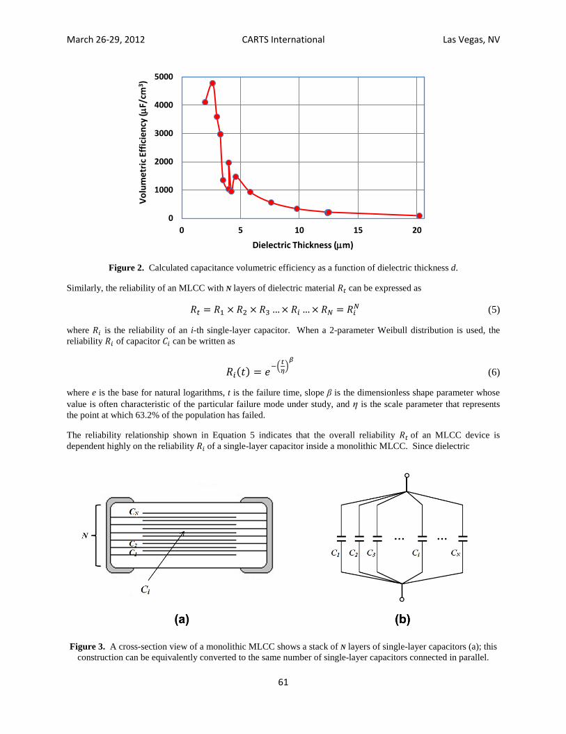
March 26-29 2012 CARTS International Las Vegas NV
62
degradation is the primary cause of the long-term reliability failure of a single-layer capacitor it is reasonable to assume that the reliability 119877119894 is mainly determined by that of the ceramic BaTiO3 dielectric material
In many situations the 119877119894 of a dielectric material can last more than thousands of years at the use level without showing significant degradation leading to high overall reliability 119877119905 However if 119877119894 is reduced slightly the overall reliability 119877119905 of a MLCC can be degraded rapidly due to the ldquoamplifyingrdquo effect from the number of dielectric layers N Table I summarizes the calculated 5-year reliability of 119877119905 from Equation 5 as a function of single dielectric layer reliability 119877119894 as well as the number of dielectric layers N It is interesting to note that when the reliability of a single-layer capacitor 119877119894 is very close to unity the number of dielectric layers N does not have a significant impact on the overall reliability 119877119905 However if 119877119894 is not close to unity the MLCC reliability 119877119905 will be degraded much more quickly if the number of dielectric layers N is significantly large
Table I Calculated 5-year reliability 119877119905 of an MLCC device with respect to 119877119894 and N Ri (5 yr) Rt (5 yr) with N =20 Rt (5 yr) with N =200 Rt (5 yr) with N =500 099999 099980 099800 099501 099990 099800 098020 095123 099900 098019 081865 060638 099000 081791 013398 000657
The results summarized in Table I reveal some important facts about the reliability of an MLCC with respect to its structure (1) the overall reliability 119877119905 of an MLCC is primarily determined by 119877119894 the reliability of the dielectric material in a single-layer capacitor (2) the number of dielectric layers N behaves more like a secondary factor to accelerate the degradation of the reliability 119877119905 if 119877119894 is only slightly reduced (3) since BME capacitors normally have a much higher value of N if the overall reliability 119877119905 is assumed to be identical for both PME and BME capacitors the reliability of the single-layer dielectric 119877119894 should be much higher for the BME capacitors This latter fact is one of the reliability challenges for BME capacitors with a large number of dielectric layers N
What Happened When the Dielectric Layer Became Thinner
In 2010 Intel reported a worrying trend with respect to the life reliability of BaTiO3-based high volumetric efficiency MLCCs [4] Numerous hours of qualification data of MLCCs for decoupling applications to support Intel CPUs initially showed that the failure due to dielectric wearout would not be a concern this is because their reliability model indicated that MLCCs could generally be used for thousands of years before the insulating resistance (IR) would begin to degrade However in the last five years it has been noticed that as capacitance volumetric efficiency has increased the usable life of MLCCs has been reduced to hundreds then tens and sometimes even less than five years This rapid life reliability degradation has been attributed to the method by which volumetric efficiency of MLCCs has increased ie the stacking up of hundreds of layers of dielectric material with an accompanying further reduction in dielectric layer thickness
Based on our discussions on 119862119905V and on 119877119905 with respect to 119877119894 and N in the previous sections we may gain better insight into the failure mechanisms in these high 119862119905V MLCCs that were reported by Intel First as shown in Figure 2 the 119862119905V of an MLCC may not be increased without limit Second the calculated results in Table I indicate that the overall reliability 119877119905 of an MLCC will not be significantly reduced only by an increase in the number of dielectric layers N as long as the single-layer capacitor reliability 119877119894 is very close to unity A significant reduction in 119877119905 implies a simultaneous reduction in 119877119894
When a 2-parameter Weibull model is used the reliability 119877119894 is only dependent on the Weibull parameters β and η The rapid reduction in 119877119905 may suggest two possibilities (1) 119877119894 only declined slightly however due to the ldquoamplifyingrdquo effect of a large number of N a significant reduction in 119877119905 could be observed (2) a failure mode other than regular dielectric wearout might have been introduced when d became smaller and smaller and resulted in a fair amount reduction in dielectric reliability 119877119894
On the other hand the trend shown in Figure 4 reveals an important fact the thinner the dielectric thickness d the higher the electric field applied to the dielectric layer This suggests that with continuous reduction of d the MLCC may be operated under electrical overstress conditions It is important to find out whether this overstress would
March 26-29 2012 CARTS International Las Vegas NV
63
Figure 4 The trend in dielectric thickness reduction as reported by Intel As the dielectric thickness decreases electrical field increases [4]
introduce new failure modes that could cause significant reliability degradation in MLCCs with thinner dielectric layers
Failure Mechanism under Overstress Conditions
1 Accelerating Stress Testing and Weibull Model In general most overstress tests for reliability estimation employ a number of highly accelerated stress levels such as voltage V and temperature T In order to gain insight into the influence of the electrical overstress on the overall reliability 119877119905 with respect to the reduction of d a number of MLCCs from various manufacturers with the same rated voltage but different dielectric thicknesses were selected for a number of reliability tests under various highly accelerated testing (HAT) conditions
It is widely known that the failure rate for MLCCs that is caused by a single failure mode when both V and T are changed from V1 to V2 and T1 to T2 is the product of the separate acceleration factors
119860119881119879 = 119877119886119905119890(1198791)119877119886119905119890(1198792)
∙ 119877119886119905119890(1198811)119877119886119905119890(1198812)
= (11988121198811
)119899 ∙ 119890minus(119864119904 119870119861frasl ) 11198791minus 11198792 (7)
where n is an empirical parameter that represents the voltage acceleration factors 119864119878 is an activation energy that represents the temperature acceleration factor and 119896119861is the Boltzman constant
This so-called Prokopowicz and Vaskas equation (P-V equation) has proven to be useful in the capacitor industry for testing MLCCs at various highly accelerated testing conditions [5] An average of n ~3 has been found for the voltage acceleration factor and an average value of 1 lt 119864119878 lt 2 eV is typical for the temperature acceleration factor [6-9]
When a 2-parameter Weibull model is applied according to Equation 7 the Weibull distribution scale parameter η can be expressed as
120578(119881119879) = 119862119881119899∙ 119890(119861119879) (8)
where C and B = 119864119878119896119861 are constants When Equations 6 and 8 are combined the reliability of a MLCC 119877119905(119905) can be expressed as
March 26-29 2012 CARTS International Las Vegas NV
64
119877119905(119905) = 119890minus119905119881
119899119890minus119861119879
119862
120573
(9)
The purpose of HAT testing is to predict the reliability life of capacitors under a normal non-accelerated operating condition In this study the ldquonormal use-level conditionrdquo refers to the capacitors being operated at room temperature (300K) and at rated voltage (Vr) When accelerating factors n and B = 119864119878119896119861 are known the reliability life tR of a unit for a specified reliability starting the mission at zero can be determined by
119905119877 = 120578minus119897119899119877119905(119905119877)1120573 = 119862119881119899∙ 119890(119861119879)
⎩⎪⎨
⎪⎧minus119897119899
⎣⎢⎢⎢⎡
119890minus119905119877119881
119899119890minus119861119879
119862
120573
⎦⎥⎥⎥⎤
⎭⎪⎬
⎪⎫
1120573 (10)
Note that this is the life for which the unit will function successfully with a reliability of 119877(119905119877) If 119877(119905119877) = 05 then 119905119877 = the median life [10]
When the maximum likelihood estimation method previously described by Nelson [10] is applied reliability and accelerating parameters B β C and n in Equation 9 can all be determined Furthermore all reliability data points tested under HAT conditions may be extrapolated and normalized individually to their use-level conditions using Equation 10 The approach from Equation 10 when compared to that of Equation 7 is more effective for determining the use-level reliability of each test point when mixed failure modes are present
2 Highly Accelerated Test Results and Discussion A number of MLCCs manufactured using both BME and PME technology with 25 V rated voltage and various chip sizes and capacitances were tested at accelerated stress levels The tests were performed at three different temperatures (155 degC 165 degC and 175 degC) and at three voltages (150 V 200 V and 250 V) for all units Table II summarizes the specifics of the MLCC samples that are to be HAT tested in this study Although most of the capacitors are 25 V rated the dielectric thickness varies significantly There is one PME capacitor sample that is rated only at 5 V in Table I The reason for including this 5 V-rated unit when all of the other capacitors are rated at 25 V is because this PME capacitor has a relatively thick dielectric layer when compared to other BME capacitors but it is still thinner than the MIL-PRF-123 minimum dielectric thickness requirement of 20 microm
Table II Microstructure Data of 25 V MLCCs with Respect to Dielectric Thicknesses
Capacitor ID Cap (microF) Chip Size Mfg Processing Technology Dielectric Thickness (microm) Avg Grain
Size (microm) A08X22525 220 0805 A BME 35 031
A08X15425 015 0805 A BME 98 046
A06X10425 010 0603 A BME 76 047
B06X22425 022 0603 B BME 42 034
B08X33425 033 0805 B BME 58 042
B08X10525 100 0805 B BME 46 040
C06X10525 100 0603 C BME 31 044
C08X22525 220 0805 C BME 40 032
D06X10405 010 0603 D PME 124 068
D08X10425 010 0805 D PME 202 061
Figure 5 shows use-level Weibull probability plots of some MLCC samples that were HAT tested in this study Each data point in Figure 5 was extrapolated using Equation 10 This was done for each failure and for any suspensions that were entered and then the median ranks of the failures were determined The data points were
March 26-29 2012 CARTS International Las Vegas NV
65
Figure 5 Use-level Weibull probability plots of typical BaTiO3 ceramic capacitors with 25 V rating All data points are extrapolated using Equation 10 and best fitted using a single 2-parameter Weibull model
Upper left 022 microF 0603 manufacturer B upper right 015 microF 0805 manufacturer A Lower left 056 microF 0805 manufacturer C lower right 001 microF 0805 manufacturer A
ldquobest fittedrdquo using a single 2-parameter Weibull model (indicated by straight lines for each plot in Figure 5) Although the majority of the data points fit the Weibull model very well a number of ldquoearly failuresrdquo are as shown in Figure 5 at the lower left corner near the fitted curve for almost every capacitor sample in this study The early failures also caused a slight curve at the bottom of the distribution indicating a subpopulation that fits a line with a smaller slope parameter β value and a lower time parameter η It suggests that these parts failed earlier than the majority of the failed parts with higher β and η values at a given HAT testing condition Similar results were also reported previously for HAT-tested MLCCs [8]
As described in our previous report [11] all capacitors listed in Table II exhibited a minimum of 105 years of reliability life at use-level when the early failures were removed for the statistical calculations In this report however the statistical calculations of early failures will be the focus of the discussion
Figure 6 shows the 2-parameter Weibull plot for capacitor sample A06X10425 The plot contains a ldquodogleg bendrdquo characteristic ie a shallow slope followed by a steep slope The plot is usually caused by mixtures of more than one failure mode The failure modes shown in Figure 6 can be statistically separated using a mixed bi-Weibull approach based on the likelihood ratio test [10]
The results of bi-Weibull modeling reveal a slope parameter β =154 for the first data set indicating an early wearout failure mode (1ltβ lt4) followed by a failure mode with a slope parameter of β =847 which is usually defined as rapid wearout (β gt4) as described in reference 13 Corresponding contour plots of the two failure modes
Calculated Use Level Probability Weibull of B06X22425
Time-to-Failure (Minutes)
Norm
al Pe
rcen
tile
100E+9 100E+13100E+10 100E+11 100E+12010
050
100
500
1000
5000
9000
9990
010
Use Level Probablity Weibull of A08X15425
Time-to-Failure (Minutes)
Norm
al Pe
rcen
tile
100E+12 100E+16100E+13 100E+14 100E+15010
050
100
500
1000
5000
9000
9990
010
Use Level Probablity Weibull of C08X56425
Time-to-Failure (Minutes)
Norm
al Pe
rcen
tile
100E+13 100E+16100E+14 100E+15010
050
100
500
1000
5000
9000
9990
010
Use-Level Probablity of A06X10425
Time-to-Failure (minutes)
Norm
al Pe
rcen
tile
100E+12 100E+15100E+13 100E+14010
050
100
500
1000
5000
9000
9900
010
March 26-29 2012 CARTS International Las Vegas NV
66
Figure 6 Statistical separation of mixed failure modes using bi-Weibull modeling Corresponding contour plots reveal the existence of two independent failure modes
reveal no crossover with respect to β and η This indicates that the split data followed two different failure modes and the separation of the two failure modes is statistically a success
The bi-Weibull modeling procedure that has been used to separate the early wearouts from rapid wearouts as shown in Figure 6 was repeatedly applied to the use-level Weibull data for the rest of the capacitor samples listed in Table II The calculated Weibull parameters and the corresponding 5-year reliability are summarized in Table III To ease comparison measurements for dielectric thickness d are also included Due to the limited availability of early failure data points some of the β values in Table III are estimates However as will be discussed in the next section the percentage of early failures was determined independently from a capacitorrsquos leakage current measurement
It is worthy to note that after bi-Weibull modeling all early failures exhibit a Weibull slope parameter of β gt 1 This indicates that these failures are not infant mortalities and therefore may not be completely removed by a regular burn-in process
Table III Early Failures in MLCCs with Respect to Dielectric Thicknesses
Capacitor ID Percent of early failures ()
Weibull Slope Parameter β 5-Year Reliability Dielectric Thickness
(microm) A08X22525 76 169 00 35 A08X15425 11 146 10 98 A06X10425 23 138 10 76 B06X22425 45 170 00 42 B08X33425 24 423 10 58 B08X10525 43 177 00 46 C06X10525 80 118 00 31 C08X22525 60 122 00 40 D06X10405 9 224 10 124 D08X10425 0 NA 10 202
Early Failures and Reliability of BaTiO3-Based Ceramic Capacitors
1 Early Failures as a Function of Dielectric Thickness and Overstress Although the Weibull parameters of early failures were statistically determined using a bi-Weibull model the actual percentage of early failures as summarized in Table III was determined experimentally As discussed in a previous report [11] when the leakage current of each capacitor is monitored as a function of testing time all early failures show an avalanche-like leakage current breakdown characterized by a sudden and extremely rapid increase in
Bi-Weibull Modeling of A06X10425
Time-to-Failure (minutes)
Norm
al Pe
rcen
tile
100E+12 100E+15100E+13 100E+14010
050
100
500
1000
5000
9000
9900
010
β =847
β =154
Contour Plot of A06X10425
5000 4000012000 19000 26000 3300000
120
24
48
72
96
Time Parameter Eta
Slop
e Par
amet
er B
eta
Early Wearout
Rapid Wearout
March 26-29 2012 CARTS International Las Vegas NV
67
leakage current without any initial gradual increase in leakage current Indeed the early failures can be divided into three groups
(1) The failures that occurred at the very beginning of HAT testing when the testing conditions were just set up Most of the failures found in test samples of capacitor A08X22525 belong to this group These failures are also dominant for some of the MLCCs with smaller dielectric thicknesses However they were not used for bi-Weibull calculations since they failed almost instantly
(2) At a given accelerated testing voltage and temperature early failures always occurred first regardless of the combination of temperature and voltage The early failures also form a subpopulation with a smaller β and lower η in comparison to the subsequent rapid wearout failures These early failures represent a subgroup that shows relatively poor reliabilities
(3) As accelerating test conditions became more aggressive the number of early failures increased significantly This may result in slope parameter β being transformed to a smaller value with respect to those observed with lesser accelerated testing conditions This is clear evidence that early failures result in a new failure mode due to electrical overstress conditions The more aggressive the overstress conditions the higher the number of early failures that would be revealed
Figure 7 shows the experimentally determined percentage of early failures as a function of measured dielectric thickness d The calculated 5-year reliability data from Equation 6 are also plotted together Under the same accelerating conditions the percentage of early failures increases significantly with decreasing dielectric thickness d It is evident that a new failure mode has been introduced when d lt 6 microm In the meantime the 5-year reliability decreases dramatically as early failures become the dominant failure mode
Although d asymp 6 microm appears to be much greater than d asymp 1 microm for a dielectric thickness at which the capacitor reliability degraded rapidly as shown in Figure 4 the stress level used in Figure 7 is also much higher than the Intel operating voltage of 12 V However if the failure mode revealed in Figure 7 is the same as that which causes the reliability degradation in Figure 4 the reliability degradation in MLCCs will occur at a greater dielectric thickness when the operating voltage shown in Figure 4 is increased beyond 12 V
Figure 7 Percentage of experimentally determined early failures and calculated 5-year Weibull reliability as a function of dielectric thickness d
Finally it is important to point out that although the early failures failed with an avalanche-like-like leakage current breakdown the failure is indeed a thermal breakdown that was caused by a rapid temperature increase due to a sudden increase in the capacitor current that generates excessive heat to destroy the dielectric structure There is a fundamental difference between an avalanche-like breakdown in ceramic capacitors and an avalanche-like breakdown in diodes that represents a typical electrical breakdown The reason for this is simple The thermal
00
02
04
06
08
10
0
10
20
30
40
50
60
70
80
90
100
0 5 10 15 20
Perc
enta
ge o
f Ear
ly F
ailu
res
()
Dielectric Thickness (microm)
5-Year Reliability
March 26-29 2012 CARTS International Las Vegas NV
68
conductivity of ceramic BaTiO3 is more than 100 times smaller than that of a silicon-based diode The massive heat generated by an avalanche-like leakage current will not be dissipated fast enough to prevent the rapid temperature increase in a ceramic capacitor
2 The Impact of Early Failures on the Reliability of BaTiO3 Ceramic Capacitors It has been reported that the avalanche-like leakage current breakdown failure of ceramic capacitors can be attributed to minor extrinsic construction defects introduced during capacitor fabrication [14] In a previous report [11] we have processed a number of MLCC samples for cross-section examination of the defect types and feature sizes of the extrinsic defects The results revealed that micro-voids were occasionally observed among the grain boundaries but cracks and delamination were rarely found In addition a number of failure analyses were also performed on the MLCC samples that had failed due to an avalanche-like breakdown Figure 8 shows a cross-section SEM image and a corresponding energy dispersive X-ray (EDX) map of a BME capacitor that failed with an avalanche-like breakdown The SEM image shows voiding at the defect site
Figure 8 Cross-section SEM image (left) and EDX map (right) of a BME capacitor that failed with an avalanche-like breakdown The voiding and carbon calcium contamination introduced during manufacturing are revealed
The matching EDX map appears to show a short between opposing electrodes of the capacitor A white arrow points to the location of carbon and calcium contaminations likely introduced during manufacturing The original defect size appears to be almost equivalent to the grain size of BaTiO3
Additional failure analysis results showed that the most common observed defects in a MLCC failed with an avalanche-like breakdown are the grains with an initial inhomogeneous element distribution due to incomplete solid-state reactions during the formation of the BaTiO3 compound Size-wise these defects are approximately of the average grain size of a BaTiO3 dielectric
The extrinsic defects that may not be removed by a burn-in process are also called ldquofreaksrdquo [8] The failure rate of a ldquofreakrdquo extrinsic defect depends on dielectric thickness and external stress levels When the dielectric thickness is far greater than the feature size of the defects most of the defects are non-harmful and may not cause any failures for many years or even during a devicersquos lifetime when used at regular use-level conditions However as the dielectric thickness approaches the feature size of the defects the non-harmful defects can cause catastrophic dielectric damage
As showing in Figure 9 assuming the feature size of an extrinsic defect is r and d is the dielectric thickness the reliability of dielectric 119877119894 can be written as 119877119894 rarr 1 when d gtgt r and 119877119894 rarr 0 when d asymp r For a 2-parameter Weibull distribution the reliability 119877119894 with respect to dielectric thickness d and size r can be expressed as
119877119894(119905) = 119890minus119905120578120573
1 minus 119903119889120572 (11)
where
119875 = 1 minus 119903119889120572
(120572 ge 5) (12)
March 26-29 2012 CARTS International Las Vegas NV
69
is a geometric factor that determines the reliability of a dielectric layer in terms of the ratio 119903119889 and 120572 is an empirical constant that depends only on the processing condition and microstructure of a ceramic capacitor In general the value of empirical parameter α is assumed to be 120572 ge 5 and can be determined experimentally Equation 11 can be applied to explain the reliability degradation behavior shown in Figure 7
From the failure analysis results discussed earlier if the feature size of a freak defect approximates the average grain size we have
119903119889 asymp 1
119899119906119898119887119890119903 119900119891 119904119905119886119888119896119890119889 119892119903119886119894119899119904 119901119890119903 119889119894119890119897119890119888119905119903119894119888 119897119886119910119890119903 (13)
The proposed reliability model as described in equations (5) (11) and (13) indicates that the overall reliability of a MLCC can be approximately estimated using only dielectric thickness average grain size and number of dielectric layers if the failure mode is caused by extrinsic defects (freaks)
(a) (b)
Figure 9 An illustration of dielectric thickness d with respect to the feature size r of an extrinsic defect inside the dielectric layer
The dielectric layer reliability is dependent on the ratio rd (a) d gtgt r (b) d asymp r
3 How Can the Reliability of BaTiO3-Based MLCCs Be Improved So far we have demonstrated that early failures are the primary cause of reliability degradation in BaTiO3-based ceramic capacitors when dielectric thickness is reduced and the MLCCs are operated under electrical overstress conditions The overstress testing results of MLCCs show that at a given external electric field the number of early failures is inversely proportional to the dielectric thickness All early failures failed with avalanche-like leakage current characteristics and the failures can be attributed to extrinsic minor defects These defects have a typical feature size equivalent to the average grain size of a BaTiO3 dielectric In addition all early failures can behave in one of two ways they can stay benign for a long time (perhaps beyond the required lifetime) or they can cause catastrophic dielectric damage depending on the level of external stress and the dielectric thickness
Since extrinsic processing defects can never be completely eliminated the best outcome would be to keep potential early failures benign during the lifetime of an MLCC This can be achieved if a minimum dielectric thickness is set at a given electrical stress level This is exactly the same approach that has been implemented with high-reliability PME ceramic capacitors Paragraph 341 of MIL-PRF-123 is cited here as a reference ldquoCapacitors supplied to this specification shall have a minimum dielectric thickness of 20 microm for 50 volt rated capacitors or 25 microm for capacitors with ratings above 50 voltsrdquo
A comparison of microstructures for both BME and PME MLCCs has shown that BME capacitors generally exhibit a denser and more uniform microstructure with relatively small grain size (03~04 microm for BME versus asymp 1 microm for PME capacitors) At a given rated voltage the minimum dielectric thickness for BME capacitors should therefore be smaller than that for PME capacitors The results shown in Figure 7 suggest that the minimum dielectric thickness for 25 V is about 6 microm Further testing data from manufacturers should be encouraged to establish a realistic minimum dielectric thickness versus voltage rating for BME capacitors under consideration for high-reliability applications NASArsquos widely used voltage de-rating method is another effective method for further guaranteeing the long-term reliability of MLCC capacitors Finally many MLCC manufacturers may have developed their own screening process to eliminate some of the extrinsic defects and the practice can be further evaluated and improved
March 26-29 2012 CARTS International Las Vegas NV
70
Summary
Volumetric efficiency (microFcm3) of a MLCC may not be increased without limit Since the dielectric constant of ceramic BaTiO3 is confined by the grain size effect the volumetric efficiency will reach a peak and then decline with further reduction in dielectric thickness
The reliability of an MLCC is mainly determined by the reliability of the single dielectric layer The number of dielectric layers N in an MLCC behaves like an amplifying factor to make a problematic part degrade more quickly BME capacitors usually have a higher N and will pose a higher demand for dielectric material reliability
When tested under electrical overstress conditions all 25 V-rated BME and some 5 V-rated PME capacitors revealed Weibull reliability plots with mixed failure modes early failures and rapid wearout failures Early failures are characterized with a lower value of the slope parameter β and a smaller time parameter η and these early failures will result in reduced reliabilities for MLCCs But the early failures are not infant mortalities and may not be completely removed by a burn-in process The percentage of early failures is inversely proportional to dielectric thickness d When d is below 6 microm the reliability 119877119905 of studied 25V MLCCs decrease dramatically accompanied by a rapid increase in the percentage of early failures
All of the early failures exhibit an avalanche-like breakdown leakage current characterized by a sudden and extremely rapid increase in leakage current without any initial gradual increase in leakage current Early failures are due to the extrinsic minor construction defects introduced during capacitor fabrication Corresponding failure analysis results show that most of the extrinsic defects are the grains with inhomogeneous composition or contamination during the formation of BaTiO3 phase The typical feature size of these defects is similar to the grain size of BaTiO3 dielectrics A reliability model with respect to the dielectric thickness d and extrinsic defect feature size r was proposed and used to explain the reliability degradation due to the reduction of d The model can be used to explain the Intel-reported reliability degradation in MLCCs with respect to the reduction of d It can also be used to estimate the reliability of a MLCC based only on its microstructure and construction parameters such as dielectric thickness average grain size and number of dielectric layers
Preventing the reliability degradation of MLCCs that results from early failures requires a means by which potential early failures can be kept benign during the lifetime of an MLCC This can be done by establishing a minimum dielectric thickness at a given voltage rating a method that is currently being applied to high-reliability PME capacitors Voltage de-rating is clearly another effective method for preventing early failures
Acknowledgements
Author David Liu appreciates the NASA Electronic Parts and Packaging (NEPP) programrsquos support for this study The authors are also thankful to Dr Henning Leidecker for valuable discussion and to B Wang and N Heng at the GSFC Code 562 Parts Analysis Laboratory for assistance with electrical testing Thanks are also due to the managers and engineers at various capacitor manufacturers for sampling and for useful discussions
References
1 Y Sakabe N Wada and Y Hamaji ldquoGrain size effects on dielectric properties and crystal structure of fine-grained BaTiO3 ceramicsrdquo J of Korean Phys Soc 32[2] pp S260-S264 1998
2 A Shaikh R Vest and G Vest ldquoDielectric properties of ultrafine grained BaTiO3rdquo IEEE Transactions on Ultrasonic Ferroelectrics and Frequency Control 36[1] pp 407-412 July 1989
3 Ding S Song T Yang X and Luo G ldquoEffect of grain size of BaTiO3 ceramics on dielectric propertiesrdquo Ferroelectrics 402[1] pp 55-59 2010
4 C Hendricks Y Min T Lane and V Magadala ldquoWhat is happening to the long term life of MLCCsrdquo CARTS proceedings pp 3-11 2010
5 T I Prokopowicz and A R Vaskas ldquoResearch and development intrinsic reliability subminiature ceramic capacitorsrdquo Final Report ECOM-90705-F NTIS AD-864068 Oct 1969
6 R Munikoti and P Dhar ldquoHighly accelerated life testing (HALT) for multiplayer ceramic capacitor qualificationrdquo IEEE Trans Comp Hybrids and Manuf Tech11[4] 1988
March 26-29 2012 CARTS International Las Vegas NV
71
7 BS Rawal and N H Chan ldquoConduction and failure mechanism in barium titanate based ceramics under highly accelerated conditionsrdquo AVX Tech Report 1988
8 J Paulsen and E Reed ldquoHighly accelerated lifetesting of base-metal-electrode ceramic chip capacitorsrdquo Microelectronics Reliability 42 pp 815-820 2002
9 D Liu H W Leidecker T J Perry and F S Felt ldquoAccelerating factors in life testing of high-voltage multi-layer ceramic capacitorsrdquo CARTS proceedings pp 168-73 2005
10 W Nelson ldquoAccelerated testing statistical models test plan and data analysisrdquo John Wiley and Sons pp 496 1990
11 D Liu and M Sampson ldquoReliability evaluation of base-metal-electrode multilayer ceramic capacitors for potential space applicationsrdquo CARTS proceedings pp 45-63 2011
12 D Liu ldquoFailure modes in capacitors when tested under a time-varying stressrdquo CARTS proceedings pp 210-223 2011
13 RB Abernethy ldquoThe new Weibull handbookrdquo (Fifth edition) pp 2-11 August 2008 14 M Cozzolino and G J Ewell ldquoFailure analysis of surface-mounted capacitorsrdquo Microelectronic Failure
Analysis Desk Reference 2002 Supplement pp133-141 2002
- 1 Y Sakabe N Wada and Y Hamaji ldquoGrain size effects on dielectric properties and crystal structure of fine-grained BaTiO3 ceramicsrdquo J of Korean Phys Soc 32[2] pp S260-S264 1998
- 2 A Shaikh R Vest and G Vest ldquoDielectric properties of ultrafine grained BaTiO3rdquo IEEE Transactions on Ultrasonic Ferroelectrics and Frequency Control 36[1] pp 407-412 July 1989
- 5 T I Prokopowicz and A R Vaskas ldquoResearch and development intrinsic reliability subminiature ceramic capacitorsrdquo Final Report ECOM-90705-F NTIS AD-864068 Oct 1969
- 6 R Munikoti and P Dhar ldquoHighly accelerated life testing (HALT) for multiplayer ceramic capacitor qualificationrdquo IEEE Trans Comp Hybrids and Manuf Tech11[4] 1988
- 7 BS Rawal and N H Chan ldquoConduction and failure mechanism in barium titanate based ceramics under highly accelerated conditionsrdquo AVX Tech Report 1988
- 8 J Paulsen and E Reed ldquoHighly accelerated lifetesting of base-metal-electrode ceramic chip capacitorsrdquo Microelectronics Reliability 42 pp 815-820 2002
- 9 D Liu H W Leidecker T J Perry and F S Felt ldquoAccelerating factors in life testing of high-voltage multi-layer ceramic capacitorsrdquo CARTS proceedings pp 168-73 2005
- 13 RB Abernethy ldquoThe new Weibull handbookrdquo (Fifth edition) pp 2-11 August 2008
- 14 M Cozzolino and G J Ewell ldquoFailure analysis of surface-mounted capacitorsrdquo Microelectronic Failure Analysis Desk Reference 2002 Supplement pp133-141 2002
-
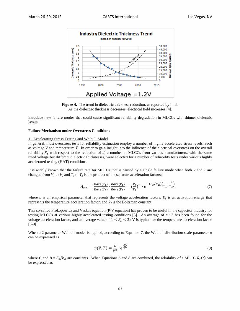
March 26-29 2012 CARTS International Las Vegas NV
71
7 BS Rawal and N H Chan ldquoConduction and failure mechanism in barium titanate based ceramics under highly accelerated conditionsrdquo AVX Tech Report 1988
8 J Paulsen and E Reed ldquoHighly accelerated lifetesting of base-metal-electrode ceramic chip capacitorsrdquo Microelectronics Reliability 42 pp 815-820 2002
9 D Liu H W Leidecker T J Perry and F S Felt ldquoAccelerating factors in life testing of high-voltage multi-layer ceramic capacitorsrdquo CARTS proceedings pp 168-73 2005
10 W Nelson ldquoAccelerated testing statistical models test plan and data analysisrdquo John Wiley and Sons pp 496 1990
11 D Liu and M Sampson ldquoReliability evaluation of base-metal-electrode multilayer ceramic capacitors for potential space applicationsrdquo CARTS proceedings pp 45-63 2011
12 D Liu ldquoFailure modes in capacitors when tested under a time-varying stressrdquo CARTS proceedings pp 210-223 2011
13 RB Abernethy ldquoThe new Weibull handbookrdquo (Fifth edition) pp 2-11 August 2008 14 M Cozzolino and G J Ewell ldquoFailure analysis of surface-mounted capacitorsrdquo Microelectronic Failure
Analysis Desk Reference 2002 Supplement pp133-141 2002
- 1 Y Sakabe N Wada and Y Hamaji ldquoGrain size effects on dielectric properties and crystal structure of fine-grained BaTiO3 ceramicsrdquo J of Korean Phys Soc 32[2] pp S260-S264 1998
- 2 A Shaikh R Vest and G Vest ldquoDielectric properties of ultrafine grained BaTiO3rdquo IEEE Transactions on Ultrasonic Ferroelectrics and Frequency Control 36[1] pp 407-412 July 1989
- 5 T I Prokopowicz and A R Vaskas ldquoResearch and development intrinsic reliability subminiature ceramic capacitorsrdquo Final Report ECOM-90705-F NTIS AD-864068 Oct 1969
- 6 R Munikoti and P Dhar ldquoHighly accelerated life testing (HALT) for multiplayer ceramic capacitor qualificationrdquo IEEE Trans Comp Hybrids and Manuf Tech11[4] 1988
- 7 BS Rawal and N H Chan ldquoConduction and failure mechanism in barium titanate based ceramics under highly accelerated conditionsrdquo AVX Tech Report 1988
- 8 J Paulsen and E Reed ldquoHighly accelerated lifetesting of base-metal-electrode ceramic chip capacitorsrdquo Microelectronics Reliability 42 pp 815-820 2002
- 9 D Liu H W Leidecker T J Perry and F S Felt ldquoAccelerating factors in life testing of high-voltage multi-layer ceramic capacitorsrdquo CARTS proceedings pp 168-73 2005
- 13 RB Abernethy ldquoThe new Weibull handbookrdquo (Fifth edition) pp 2-11 August 2008
- 14 M Cozzolino and G J Ewell ldquoFailure analysis of surface-mounted capacitorsrdquo Microelectronic Failure Analysis Desk Reference 2002 Supplement pp133-141 2002
-