solutions manual part 1 - 1&1 internet · chapter 3 - fieldwork ... preparing submittals for...
TRANSCRIPT
Instructors Manualfor
Construction Surveying and Layout
Third Edition
Part One - Surveying Field Practices
Chapters 1-10
Prepared by
Wesley G. Crawford
TABLE OF CONTENTS
Chapter 1 - Construction Surveying ........................................................................ 3
Chapter 2 - Communications .................................................................................... 4
Chapter 3 - Fieldwork Practices............................................................................... 6
Chapter 4 - Distance Measurement - Chaining ....................................................... 8
Chapter 5 - Angle Measurement ............................................................................ 11
Chapter 6 - Total Station ........................................................................................ 16
Chapter 7 - Leveling .............................................................................................. 19
Chapter 8 - Lasers .................................................................................................. 29
Chapter 9 - GPS Field Procedures ......................................................................... 30
Chapter 10 - Equipment Calibration ...................................................................... 33
Copyright 2003 - Creative Construction Publishing - 3
Construction Surveying and Layout, 3rd Edition
Chapter 1 - Construction Surveying
QUESTIONS AND PROBLEMS
1. List 10 personal tools carried by a field engineer.
1) Plumb bob
2) Hand level
3) Gammon reel
4) Fieldbook
5) 25’ or 5 meter tape
6) marking scribe
7) marking pens
8) pencils
9) calculator
10) safety vest
2. Why do you think a safety belt or harness is needed in construction layout?
It is needed whenever working in high places. Either above a deep excavation, on structural steel,or on bridges.
3. On a word processor, prepare a poster that could be hung on the wall, denoting the personal itemsyou would use for construction layout.
This can be any size that fits the situation. Possibly make it a checklist type of poster to remindwhat needs to be taken to the field
4. Prepare a bar chart of your daily schedule for a busy day of the week. Determine if it keeps youfrom forgetting activities.
This can be broken into hour or smaller time slots to show detailed activities that re-occur. Anysize is acceptable.
5. Review the success characteristics of a field engineer and determine which are most important toyou.
This is a personal evaluation. See the characteristics on page 1-8.
6. Describe the relationship between the field engineer and the superintendent.
The field engineer works for the superintendent. Depending on the company structure, the fieldengineer helps the superintendent in any way possible.
If the field engineer is from an outside company, that individual still is responsible to whatever thesuperintendent needs done.
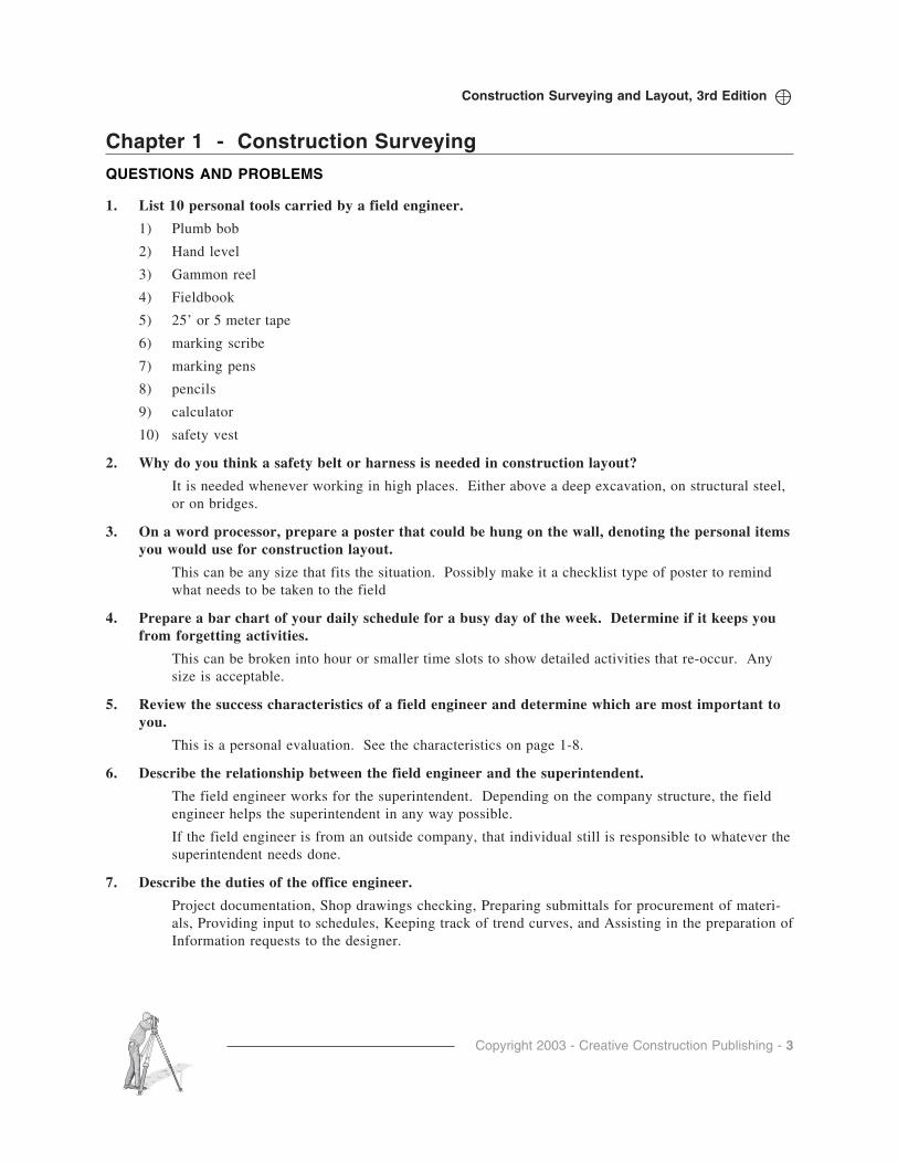
7. Describe the duties of the office engineer.
Project documentation, Shop drawings checking, Preparing submittals for procurement of materi-als, Providing input to schedules, Keeping track of trend curves, and Assisting in the preparation ofInformation requests to the designer.

Copyright 2003 - Creative Construction Publishing - 4
Construction Surveying and Layout, 3rd Edition
8. Describe the role of the field engineer in quality control.
Field Engineers are the eyes of the superintendent on the jobsite. The Field Engineer is in themidst of the work and can see the materials being placed and the craftsmanship that is beingperformed. The field engineer can see when something is wrong and may be able to get it cor-rected before it becomes permanent.
9. Establish a goal (save money, lose weight, etc.) and use a trend chart to keep track of yourprogress towards that goal.
This is a personal activity. I can attest that it works very well for weight loss…provided youexercise and stick to a diet!!
10. Contact a Registered Surveyor in your area and find out what it takes to become licensed.
Most registered surveyors would be glad to discuss their profession. If a local surveyor cannot becontacted, find out the name of the state surveying society. Visit the website of the AmericanCongress on Surveying and Mapping for the address of every state society. http://www.acsm.net/.
Chapter 2 - COMMUNICATIONS
QUESTIONS AND PROBLEMS
1. Analyze your communication habits and methods and write down five ways you could improveyourself.
1) Listen better
2) Be prepared
3) Concentrate
4) Be understanding
5) Eliminate distractions
2. What is the key to oral communication?
Listening
3. Develop a poster that you could use to remind yourself to be a better communicator.
COMMUNICATION IS KEY
• Communication is the most important part of every action.
• To develop trust on the construction site, be honest in all communications.
• To be an effective person, master the art of listening well.
• Effective letter writing is concise, makes sense, includes necessary information, and cannot be misunderstood.
• Be polite, and be on time for meetings.
• Hand and arm signals are an effective method of communicating on the construction site.
• For safety reasons, be able to communicate with a crane operator.
• Construction stakes are the communication tool used to locate the project.
• Line and grade marks are used to communicate to the craftsperson.
• Use abbreviations to reduce the size of writing on stakes.
Copyright 2003 - Creative Construction Publishing - 5
Construction Surveying and Layout, 3rd Edition
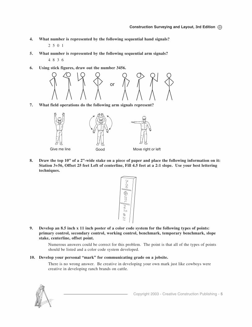
4. What number is represented by the following sequential hand signals?
2 5 0 1
5. What number is represented by the following sequential arm signals?
4 8 3 6
6. Using stick figures, draw out the number 3456.
7. What field operations do the following arm signals represent?
8. Draw the top 10” of a 2”-wide stake on a piece of paper and place the following information on it:Station 3+56, Offset 25 feet Left of centerline, Fill 4.5 feet at a 2:1 slope. Use your best letteringtechniques.
Give me line Move right or leftGood
or
3+
56
25
'LF4
@ 2
:15
9. Develop an 8.5 inch x 11 inch poster of a color code system for the following types of points:primary control, secondary control, working control, benchmark, temporary benchmark, slopestake, centerline, offset point.
Numerous answers could be correct for this problem. The point is that all of the types of pointsshould be listed and a color code system developed.
10. Develop your personal “mark” for communicating grade on a jobsite.
There is no wrong answer. Be creative in developing your own mark just like cowboys werecreative in developing ranch brands on cattle.
Copyright 2003 - Creative Construction Publishing - 6
Construction Surveying and Layout, 3rd Edition
Chapter 3 - Fieldwork Practices
QUESTIONS AND PROBLEMS
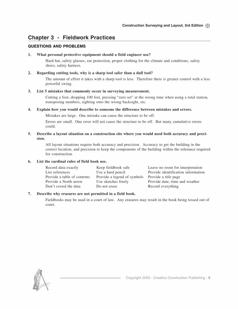
1. What personal protective equipment should a field engineer use?
Hard hat, safety glasses, ear protection, proper clothing for the climate and conditions, safetyshoes, safety harness.
2. Regarding cutting tools, why is a sharp tool safer than a dull tool?
The amount of effort it takes with a sharp tool is less. Therefore there is greater control with a lesspowerful swing.
3. List 5 mistakes that commonly occur in surveying measurement.
Cutting a foot, dropping 100 feet, pressing “zero set” at the wrong time when using a total station,transposing numbers, sighting onto the wrong backsight, etc.
4. Explain how you would describe to someone the difference between mistakes and errors.
Mistakes are large. One mistake can cause the structure to be off.
Errors are small. One error will not cause the structure to be off. But many cumulative errorscould.
5. Describe a layout situation on a construction site where you would need both accuracy and preci-sion.
All layout situations require both accuracy and precision. Accuracy to get the building in thecorrect location, and precision to keep the components of the building within the tolerance requiredfor construction.
6. List the cardinal rules of field book use.
Record data exactly Keep fieldbook safe Leave no room for interpretationList references Use a hard pencil Provide identification informationProvide a table of contents Provide a legend of symbols Provide a title pageProvide a North arrow Use sketches freely Provide date, time and weatherDon’t crowd the data Do not erase Record everything
7. Describe why erasures are not permitted in a field book.
Fieldbooks may be used in a court of law. Any erasures may result in the book being tossed out ofcourt.

Copyright 2003 - Creative Construction Publishing - 7
Construction Surveying and Layout, 3rd Edition
Equipment Care Schedule
Maintenance Item
Daily Weekly Monthly
Yearly or at Seasonal Temperature Changes
Start of New Job
When New
Wipe Clean
Deep Clean
Lubricate (Dry Teflon Spray
only)
Check and Correct
Calibration
Check Instrument Constants
Lens Cleaning
8. Develop a poster on equipment care that you would place on your job as a field engineer.
9. Discuss methods that you would use to keep instruments clean.
Keep the empty case closed
Brush dirt off of the instrument with a shaving brush.
Use compressed air to blow dirt off of an instrument.
Clean the lenses with camera cleaning supplies.
10. How is the care of electronic instruments different from other instruments?
The must be kept drier. Electronic contacts must not get wet.
11. What common food storage aid could be used to keep a calculator dry and clean on a dirty, wetconstruction site?
Zip-lock bag
12. Develop an “instrument care and maintenance” chart to be used to regularly clean equipment.
TAKE CARE OF YOUR EQUIPMENT
• Transport equipment in its case.
• Keep an empty case closed
• Attach the instrument securely to the tripod
• Do not touch the lenses.
• Allow wet instruments to air dry outside of their case.
• Establish a wide foundation
• Never force any part of an instrument
• Keep the instrument clean.
• Climatize the instrument when there are extreme weather conditions.
Copyright 2003 - Creative Construction Publishing - 8
Construction Surveying and Layout, 3rd Edition
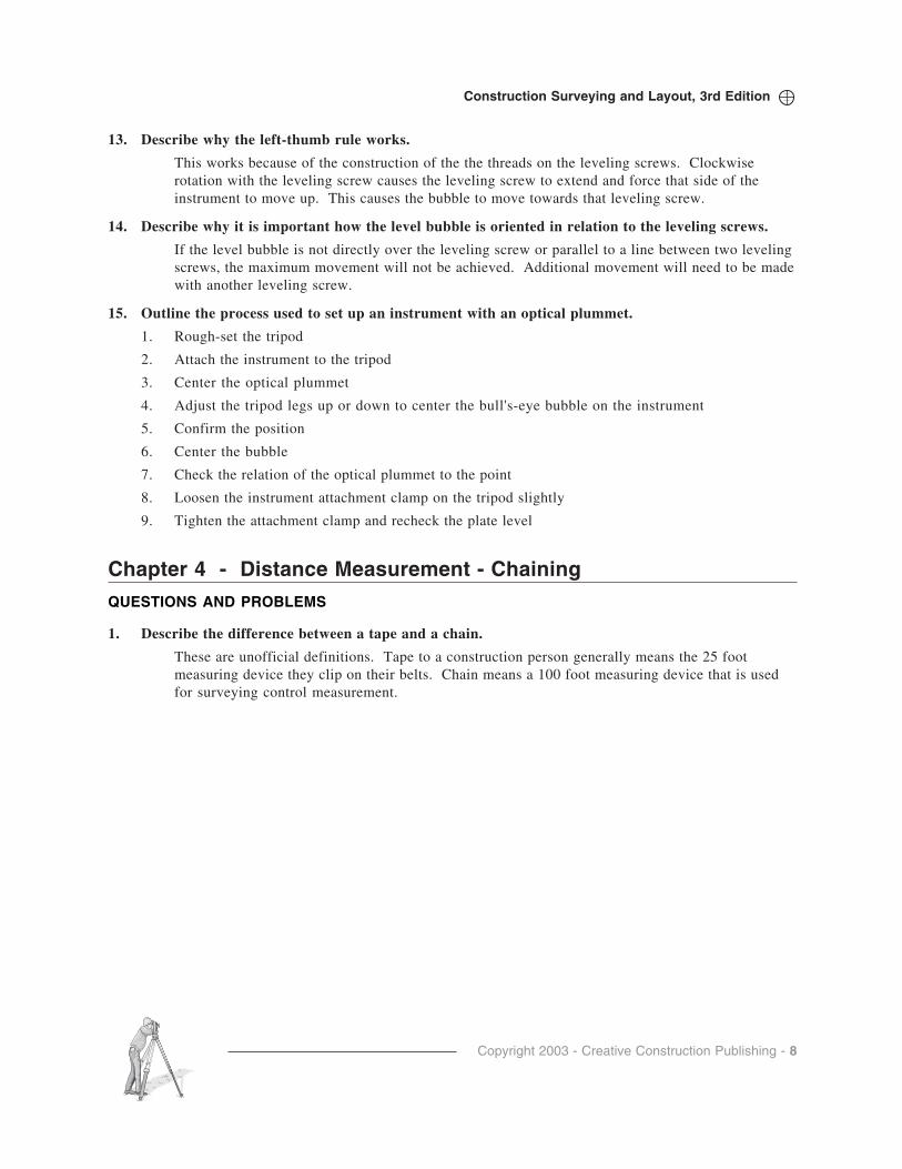
13. Describe why the left-thumb rule works.
This works because of the construction of the the threads on the leveling screws. Clockwiserotation with the leveling screw causes the leveling screw to extend and force that side of theinstrument to move up. This causes the bubble to move towards that leveling screw.
14. Describe why it is important how the level bubble is oriented in relation to the leveling screws.
If the level bubble is not directly over the leveling screw or parallel to a line between two levelingscrews, the maximum movement will not be achieved. Additional movement will need to be madewith another leveling screw.
15. Outline the process used to set up an instrument with an optical plummet.
1. Rough-set the tripod
2. Attach the instrument to the tripod
3. Center the optical plummet
4. Adjust the tripod legs up or down to center the bull's-eye bubble on the instrument
5. Confirm the position
6. Center the bubble
7. Check the relation of the optical plummet to the point
8. Loosen the instrument attachment clamp on the tripod slightly
9. Tighten the attachment clamp and recheck the plate level
Chapter 4 - Distance Measurement - Chaining
QUESTIONS AND PROBLEMS
1. Describe the difference between a tape and a chain.
These are unofficial definitions. Tape to a construction person generally means the 25 footmeasuring device they clip on their belts. Chain means a 100 foot measuring device that is usedfor surveying control measurement.
Copyright 2003 - Creative Construction Publishing - 9
Construction Surveying and Layout, 3rd Edition
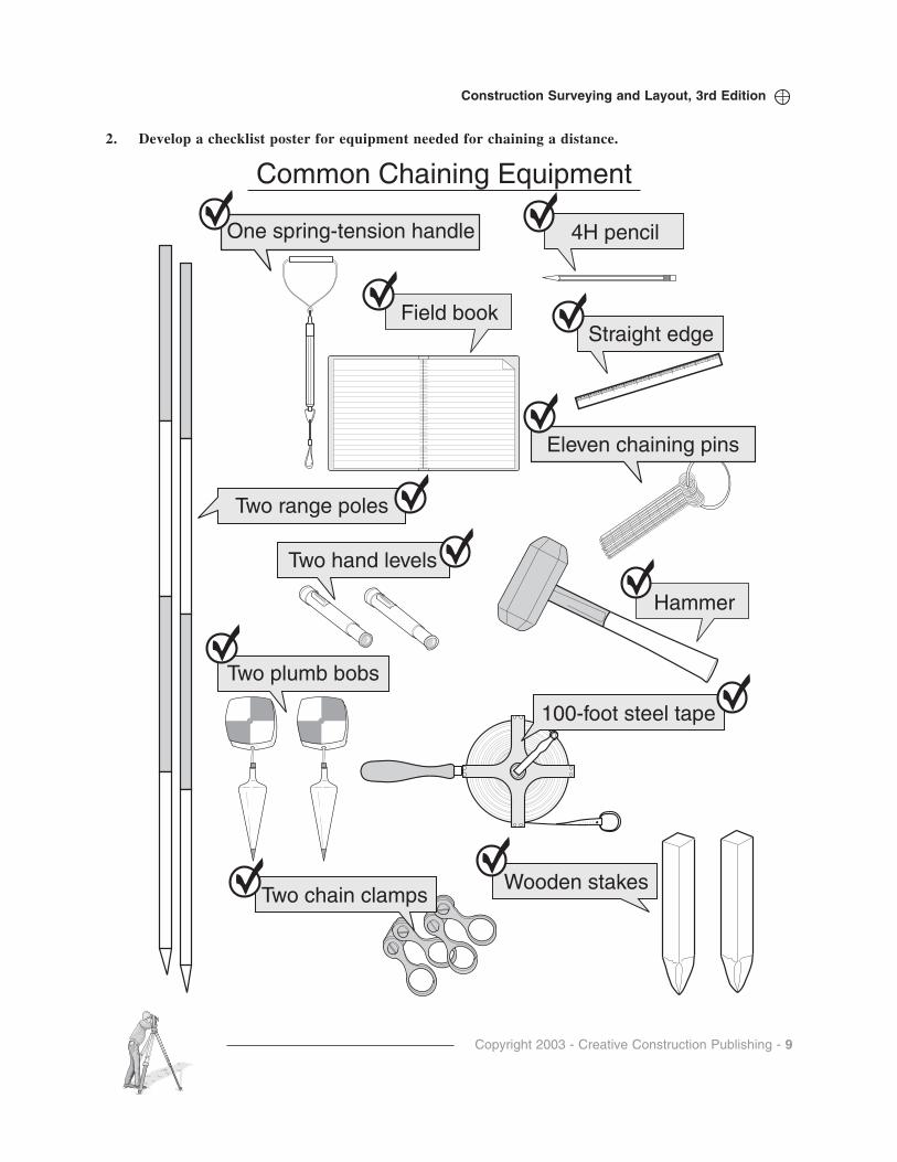
2. Develop a checklist poster for equipment needed for chaining a distance.
Common Chaining Equipment
One spring-tension handle 4H pencil
Field book
Two range poles
Two plumb bobs
Straight edge
Two hand levels
100-foot steel tape
Wooden stakes
Eleven chaining pins
Hammer
Two chain clamps
Copyright 2003 - Creative Construction Publishing - 10
Construction Surveying and Layout, 3rd Edition
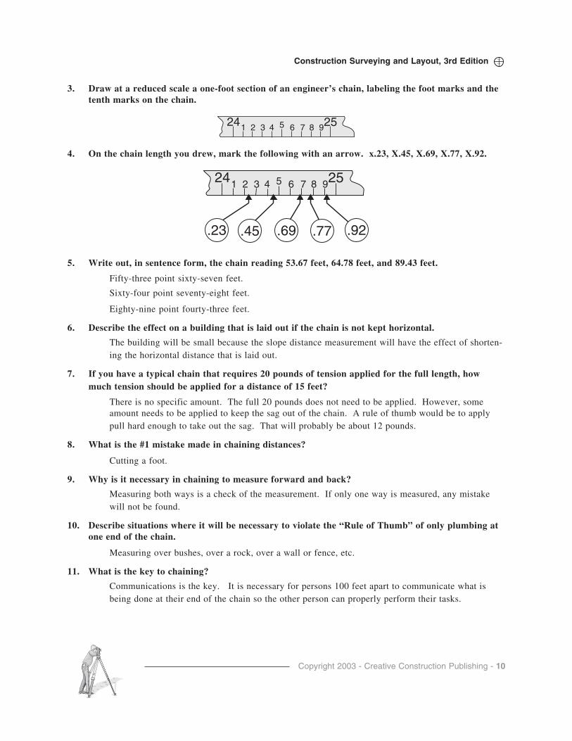
3. Draw at a reduced scale a one-foot section of an engineer’s chain, labeling the foot marks and thetenth marks on the chain.
4. On the chain length you drew, mark the following with an arrow. x.23, X.45, X.69, X.77, X.92.
5. Write out, in sentence form, the chain reading 53.67 feet, 64.78 feet, and 89.43 feet.
Fifty-three point sixty-seven feet.
Sixty-four point seventy-eight feet.
Eighty-nine point fourty-three feet.
6. Describe the effect on a building that is laid out if the chain is not kept horizontal.
The building will be small because the slope distance measurement will have the effect of shorten-ing the horizontal distance that is laid out.
7. If you have a typical chain that requires 20 pounds of tension applied for the full length, howmuch tension should be applied for a distance of 15 feet?
There is no specific amount. The full 20 pounds does not need to be applied. However, someamount needs to be applied to keep the sag out of the chain. A rule of thumb would be to applypull hard enough to take out the sag. That will probably be about 12 pounds.
8. What is the #1 mistake made in chaining distances?
Cutting a foot.
9. Why is it necessary in chaining to measure forward and back?
Measuring both ways is a check of the measurement. If only one way is measured, any mistakewill not be found.
10. Describe situations where it will be necessary to violate the “Rule of Thumb” of only plumbing atone end of the chain.
Measuring over bushes, over a rock, over a wall or fence, etc.
11. What is the key to chaining?
Communications is the key. It is necessary for persons 100 feet apart to communicate what isbeing done at their end of the chain so the other person can properly perform their tasks.
25241 2 3 4 5 6 7 8 9
25241 2 3 4 5 6 7 8 9
.23 .45 .69 .77 .92
Copyright 2003 - Creative Construction Publishing - 11
Construction Surveying and Layout, 3rd Edition
12. How should chaining pins be inserted into the ground?
At 45º to the ground so that the plumb bob can be suspended over the point where the pin goes inthe ground. And, at 90 degrees to the chain so that the measurement can be made to the center ofthe pin.
13. If the forward distance measured is 1234.56 and the back distance is 1234.67, what is the discrep-ancy ratio?
14. What is the source of error if a chain is labeled as a 100-foot chain, and it is actually found to be100.01 when compared to a calibration baseline?
Instrumental
15. List 5 random errors that might occur because of “human limitations.”
Reading the distance incorrectly.
Inserting the chaining pin,
Plumbing over the pin.
The plumb bob moving because of an unsteady hand.
Plumbing at both ends of the chain.
Etc.
Chapter 5 - Angle Measurement
QUESTIONS AND PROBLEMS
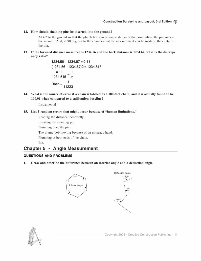
1. Draw and describe the difference between an interior angle and a deflection angle.
112231
Ratio
11234.615
0.11
1234.6151234.67)2(1234.56
0.111234.671234.56
=
=
=−=−
χ
right
left
right
Deflection angle
Interior angle
Copyright 2003 - Creative Construction Publishing - 12
Construction Surveying and Layout, 3rd Edition
2. State why it is important to turn angles direct and reverse.
This processes eliminates systematic errors in the instrument. The error may cause the angle to belarger when it is turned direct and it will cause the measured angle to be shorter when it is turnedwith the instrument reverse. Therefore, the error is balanced out and a better estimate of the truevalue is obtained by averaging out the angle.
3. How can closing the horizon check your measured angle?
Since it is known that there are 360º in a circle, the summation of the angles around a point shouldadd to 360º within the tolerance of the instruement.
4. Describe three differences between a transit, theodolite, and total station.
The Transit is an open instrument that has two bubbles, a metal circle, an upper and lower clamp, acompass, a four-screw leveling system, and generally is set over a point with a plumb bob. Thetheodolite has a single bubble, glass circle, various clamp arrangements from one clamp to twoclamps, a three screw leveling system and an optical plummet. It is generally much more compactand enclosed than a transit. The total station has many of the features of the theodolite but theangles and distances are measured electronically and the plummet may be a laser.
5. What is the main difference between a digital theodolite and a total station?
Digital theodolite just measures angles while the total station measures both distance and angle.
6. Why is a total station called a total station?
Because it is capable of all measurements, including: slope, horizontal and vertical distances,horizontal and vertical angles, coordinate displays, numerous coordinate geometry routines thatcan be accessed in the field, and often times data collection.
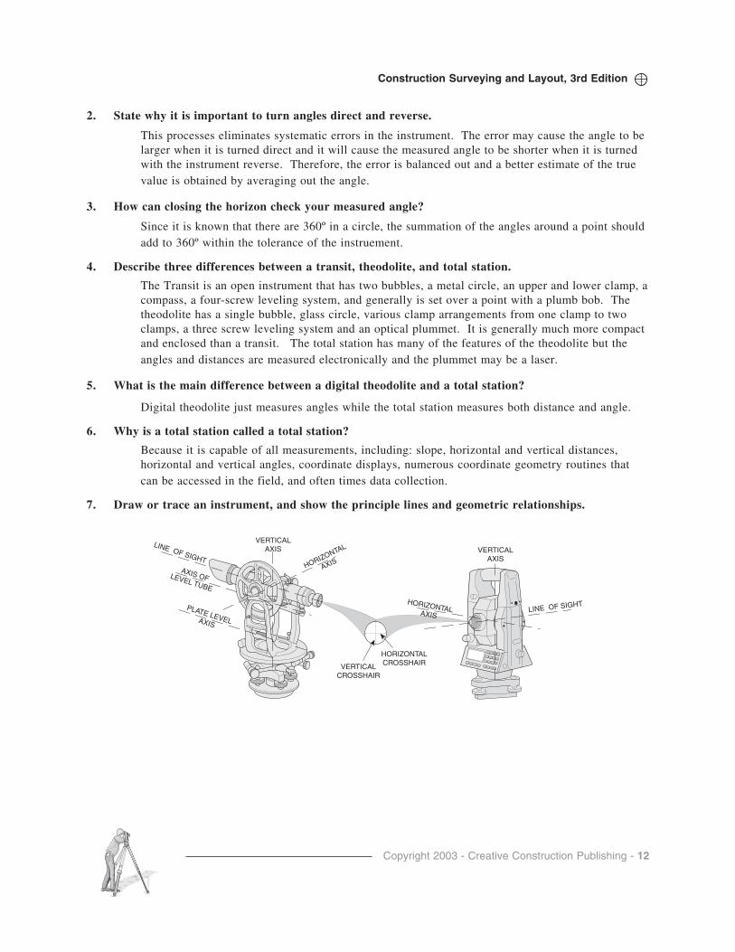
7. Draw or trace an instrument, and show the principle lines and geometric relationships.
VERTICALAXIS VERTICAL
AXISHORIZONTAL
AXIS
LINE OF SIGHT
LINE OF SIGHT
AXIS OFLEVEL TUBE
HORIZONTALCROSSHAIRVERTICAL
CROSSHAIR
PLATE LEVELAXIS
HORIZONTALAXIS
Copyright 2003 - Creative Construction Publishing - 13
Construction Surveying and Layout, 3rd Edition
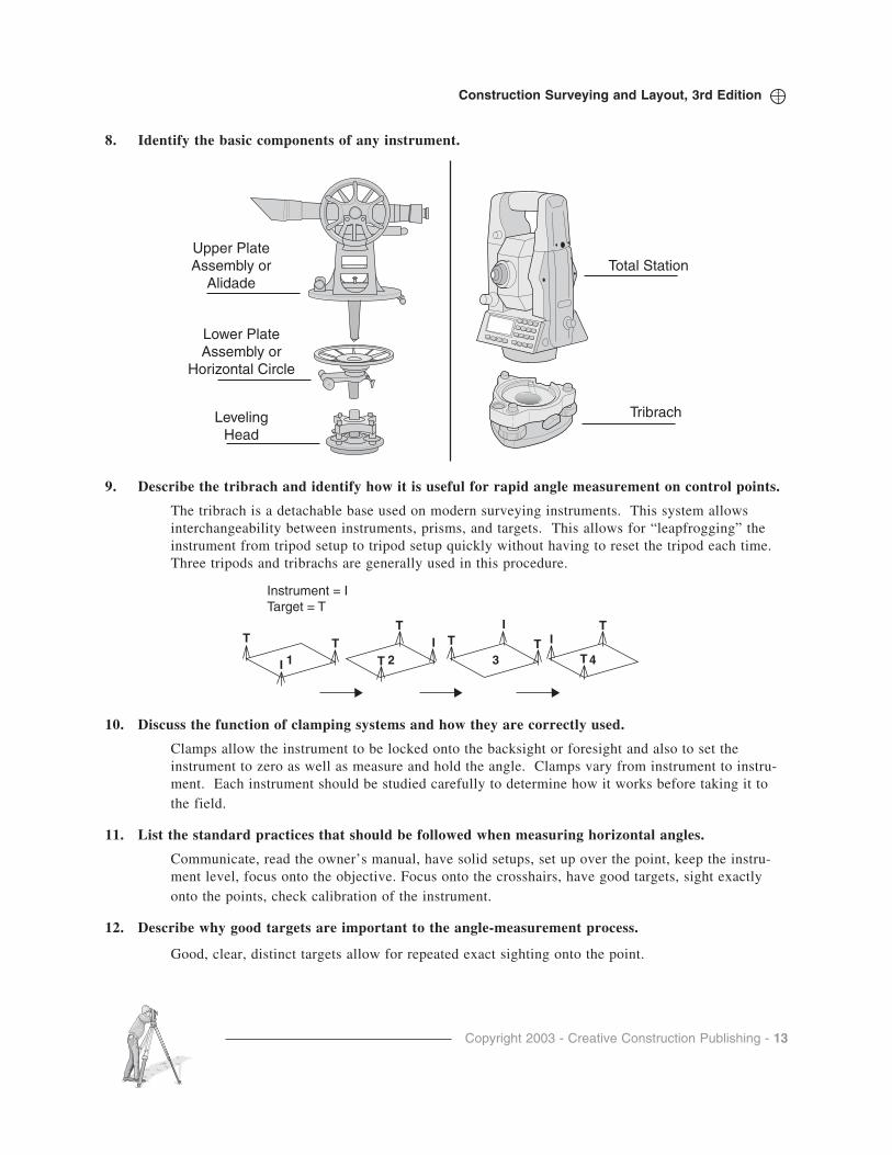
8. Identify the basic components of any instrument.
9. Describe the tribrach and identify how it is useful for rapid angle measurement on control points.
The tribrach is a detachable base used on modern surveying instruments. This system allowsinterchangeability between instruments, prisms, and targets. This allows for “leapfrogging” theinstrument from tripod setup to tripod setup quickly without having to reset the tripod each time.Three tripods and tribrachs are generally used in this procedure.
10. Discuss the function of clamping systems and how they are correctly used.
Clamps allow the instrument to be locked onto the backsight or foresight and also to set theinstrument to zero as well as measure and hold the angle. Clamps vary from instrument to instru-ment. Each instrument should be studied carefully to determine how it works before taking it tothe field.
11. List the standard practices that should be followed when measuring horizontal angles.
Communicate, read the owner’s manual, have solid setups, set up over the point, keep the instru-ment level, focus onto the objective. Focus onto the crosshairs, have good targets, sight exactlyonto the points, check calibration of the instrument.
12. Describe why good targets are important to the angle-measurement process.
Good, clear, distinct targets allow for repeated exact sighting onto the point.
LevelingHead
Upper PlateAssembly or
Alidade
Tribrach
Lower PlateAssembly or
Horizontal Circle
Total Station
Instrument = ITarget = T
4T
TI
3TT
I
2
T
T
I
I
T T1

Copyright 2003 - Creative Construction Publishing - 14
Construction Surveying and Layout, 3rd Edition
13. List and describe three “helpful hints” for reading angles.
Set zero exactly, read both ways, read in the correct direction, close the horizon, use direct andreverse.
14. Describe any difference that exists in the process of measuring an angle direct and measuring anangle reverse.
Scope is right side up when sighting direct, and the scope is upside down when turning reverseangles.
15. What geometric formula is used when comparing traverse angles to a closed figure?
(n-2)180 where n is the number of angles in the closed figure.
16. What is the basic difference between measuring an angle and laying out an angle?
Measuring is determining the angle from a existing backsight point to an existing foresight point.
Layout is measuring a calculated angle off of an existing backsight to establish a line or point atthe value of the angle.
17. Identify the single greatest mistake that can occur in angle layout.
Sighting onto a bad backsight (moved) or sighting onto the wrong backsight.
18. What is the difference between a vertical angle and a zenith angle?
Vertical angle is measured off of the horizon with up being positive and down from the horizonbeing negative.
Zenith angles are measure down from the zenith point directly above the instrument. Positive andnegative are not needed.
19. Which crosshair is used when measuring horizontal angles, and which crosshair is used whenmeasuring vertical angles?
The vertical crosshair is used when measuring horizontal angles.
The horizontal crosshair is used when measuring vertical angles.
Copyright 2003 - Creative Construction Publishing - 15
Construction Surveying and Layout, 3rd Edition
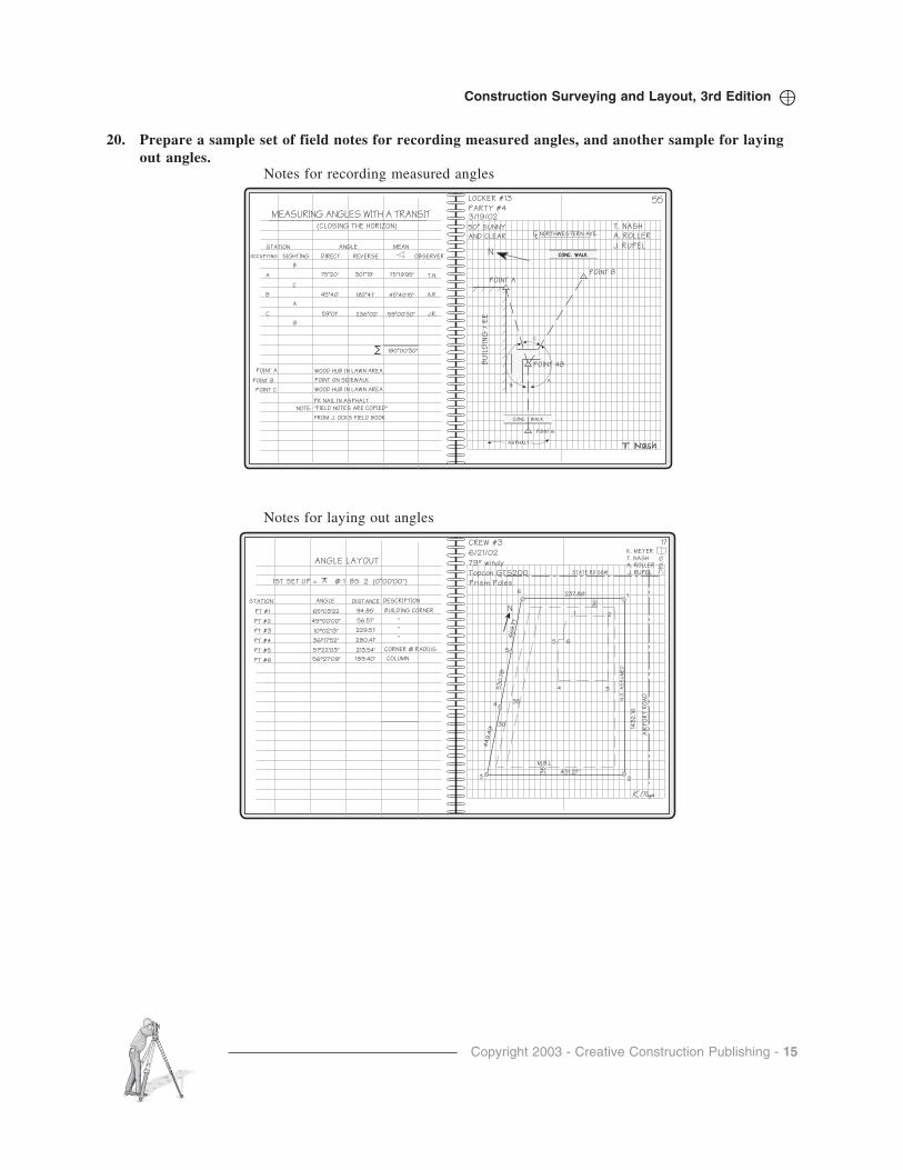
20. Prepare a sample set of field notes for recording measured angles, and another sample for layingout angles.
ANGLE LAYOUT
STATION
65º03'22
45º00'00"
10º02'13"
36º17'52"
51º22'03"
56º27'09"
ANGLE
BUILDING CORNER
"
"
"
CORNER @ RADIUS
COLUMN
DESCRIPTION
CREW #3
6/21/02
79º windy
Topcon GTS200
Prism Poles
94.85'
56.57'
229.51'
280.41'
213.54'
189.40'
1ST SET UP = @ 1 BS 2 (0˚00'00")
DISTANCE
PT #1
PT #2
PT #3
PT #4
PT #5
PT #6
M.B.L
N O
A
SS
UM
ED
431.27'
237.88'
30
53
0.7
8'
44
9.4
9'
46
9.7
1'
4 3
21
65
5
6
4
3 2
1
143
2.1
6
AIR
PO
RT
RO
AD
35
'
35
35
'
STATE RD 26W J. RUPEL
T. NASH
A. ROLLER
K. MEYER
N
17
Notes for laying out angles
MEASURING ANGLES WITH A TRANSIT
OCCUPYING
"FIELD NOTES ARE COPIED"
FROM J. OCKS FIELD BOOK
NOTE:
A
A
B
B
B
C
C
75˚20'
45˚40'
59˚01'
301˚19'
182˚41'
236˚02'
T.N.
A.R.
J.R.
SIGHTING DIRECT REVERSE OBSERVER
T. NASH
A. ROLLER
J. RUPEL
LOCKER #13
PARTY #43/19/02
50˚ SUNNY
AND CLEAR
75˚19'95"
45˚40'15"
59˚00'30"
POINT 6
POINT 4B
POINT BPOINT A
NORTHWESTERN AVE.
(CLOSING THE HORIZON)
STATION ANGLE MEAN
180˚00'30"
POINT A
POINT B
POINT C
WOOD HUB IN LAWN AREA
POINT ON SIDEWALK
WOOD HUB IN LAWN AREA
PK NAIL IN ASPHALT
CL
ASPHALT
A
C
B
CONC. WALKCONC. WALK
CONC. WALK
BU
ILD
ING
/ E
E
55
N
Notes for recording measured angles

Copyright 2003 - Creative Construction Publishing - 16
Construction Surveying and Layout, 3rd Edition
Chapter 6 - Total Station
QUESTIONS AND PROBLEMS
1. Describe why the total station is the instrument of choice on the construction site.
Versatile, rapid, greater productivity in the measurement and layout of angles and distances.
2. List and describe five advantages of using a total station.
Instant horizontal distance, quick checking of work, single instrument with great capabilities, easyto use, provides a computer in the field, data storage, etc.
3. How is a total station different from a digital theodolite?
Digital theodolite just measures angles while the total station measures both distance and angle.
4. Visit the World Wide Websites of three surveying equipment manufacturers and research themeasurement and functional capabilities of typical one-second total stations that are available.Develop a table comparing a total station from each manufacturer.
www.leica.com
www.sokkia.com
www.topcon.com
www.nikon.com
5. Describe how the relative precision of total stations would affect the layout work on a construction site.
Distance measurement with a total station is best for longer distances. At short distances, theprecision is poor.
6. Visit the World Wide Web and research the various types of total stations that are available fromone manufacturer. List and describe the types.
www.leica.com
www.sokkia.com
www.topcon.com
www.nikon.com
7. What is actually measured by the total station?
Time that it takes for the wavelength to go out and return to the instrument.
0 200 400 800 1000600 1200
10,000
60,000
50,000
40,000
30,000
20,000
DISTANCE IN FEET
CLO
SU
RE
AC
CU
RA
CY

Copyright 2003 - Creative Construction Publishing - 17
Construction Surveying and Layout, 3rd Edition
8. Why is it important to sight exactly onto the prism (target) when using a total station?
Not sighting exactly may result in poor angles measured.
9. What major mistake could occur with the zero set feature of a total station?
Pushing the “zero set” button at the wrong time during the measuring sequence can result in a hugeerror.
10. Describe the relationship of the prism to the center of the rod when the prism has a –30 mm offset.
The center of the prism is 30 mm in from of the center of the rod.
11. What is inputted to determine the parts-per-million correction factor?
Air temperature and barometric pressure
12. For the total station available to you, set up a table that lists the step-by-step procedure forpreparing the total station for measuring.
Go to your owner’s manual.
13. Outline the basic procedure for measuring a distance and an angle.
1) Set up over the point and prepare for measurements.
2) Measure the height of instrument.
3) Sight onto the backsight and set the direction.
4) Loosen the horizontal clamp and turn to the prism pole held at the foresight.
5) Sight onto the prism.
6) Measure the Distance.
7) Read and record the distance and angle.
8) Double-check.
14. From the step-by-step procedure on measuring, which person is most important to the process?
Both are equally important in performing the task. It is often said however, that the most experi-enced person should be the one at the prism because anyone can be taught in a few hours to use thetotal station, whereas it takes months of experience to be good at the various duties at the prismpole (rod holder)
15. Develop a list of equipment that is used in total station measurement.
Total station, prism pole, prism , target, tripods, case for instrument, case for prisms, chain forchecking distances, tape for measuring instrument height, hammer, hubs, tacks.
16. Describe the fundamental difference between measuring and layout.
Measuring is determining the distance between two points that are already in the ground.
Layout is the establishment of points on the ground from distances on the plans.
17. List some activities on a construction site where trigonometric elevations would be useful.
Height of pier, height of building, height of dirt pile, establishing elevations throughout the site,depth of excavation, etc.
Copyright 2003 - Creative Construction Publishing - 18
Construction Surveying and Layout, 3rd Edition
18. Why is it important to turn direct and reverse to obtain precise elevations in trigonometric leveling?
Again, this averages out any error.
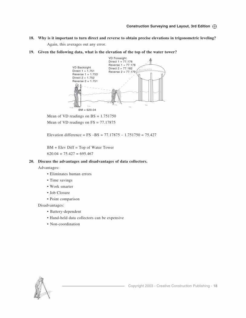
19. Given the following data, what is the elevation of the top of the water tower?
Mean of VD readings on BS = 1.751750
Mean of VD readings on FS = 77.17875
Elevation difference = FS –BS = 77.17875 – 1.751750 = 75.427
BM + Elev Diff = Top of Water Tower
620.04 + 75.427 = 695.467
20. Discuss the advantages and disadvantages of data collectors.
Advantages:
• Eliminates human errors
• Time savings
• Work smarter
• Job Closure
• Point comparison
Disadvantages:
• Battery-dependent
• Hand-held data collectors can be expensive
• Non-coordination
U n i v e r s i t yVD BacksightDirect 1 = 1.751Reverse 1 = 1.753Direct 2 = 1.752Reverse 2 = 1.751
VD ForesightDirect 1 = 77.176Reverse 1 = 77.178Direct 2 = 77.182Reverse 2 = 77.179
BM = 620.04
Copyright 2003 - Creative Construction Publishing - 19
Construction Surveying and Layout, 3rd Edition
Chapter 7 - Leveling
QUESTIONS AND PROBLEMS
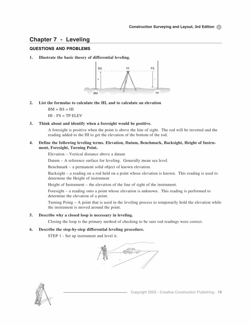
1. Illustrate the basic theory of differential leveling.
2. List the formulas to calculate the HI, and to calculate an elevation
BM + BS = HI
HI - FS = TP ELEV
3. Think about and identify when a foresight would be positive.
A foresight is positive when the point is above the line of sight. The rod will be inverted and thereading added to the HI to get the elevation of the bottom of the rod.
4. Define the following leveling terms. Elevation, Datum, Benchmark, Backsight, Height of Instru-ment, Foresight, Turning Point.
Elevation – Vertical distance above a datum
Datum – A reference surface for leveling. Generally mean sea level.
Benchmark – a permanent solid object of known elevation.
Backsight – a reading on a rod held on a point whose elevation is known. This reading is used todetermine the Height of instrument
Height of Instrument – the elevation of the line of sight of the instrument.
Foresight – a reading onto a point whose elevation is unknown. This reading is performed todetermine the elevation of a point.
Turning Poing – A point that is used in the leveling process to temporarily hold the elevation whilethe instrument is moved around the point.
5. Describe why a closed loop is necessary in leveling.
Closing the loop is the primary method of checking to be sure rod readings were correct.
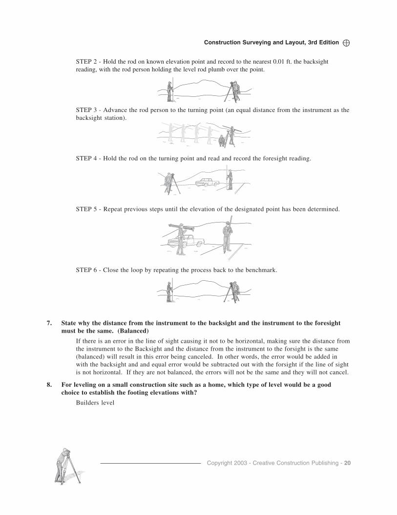
6. Describe the step-by-step differential leveling procedure.
STEP 1 - Set up instrument and level it.
BS FS
BM TP
HI
+ -
Copyright 2003 - Creative Construction Publishing - 20
Construction Surveying and Layout, 3rd Edition
STEP 2 - Hold the rod on known elevation point and record to the nearest 0.01 ft. the backsightreading, with the rod person holding the level rod plumb over the point.
STEP 3 - Advance the rod person to the turning point (an equal distance from the instrument as thebacksight station).
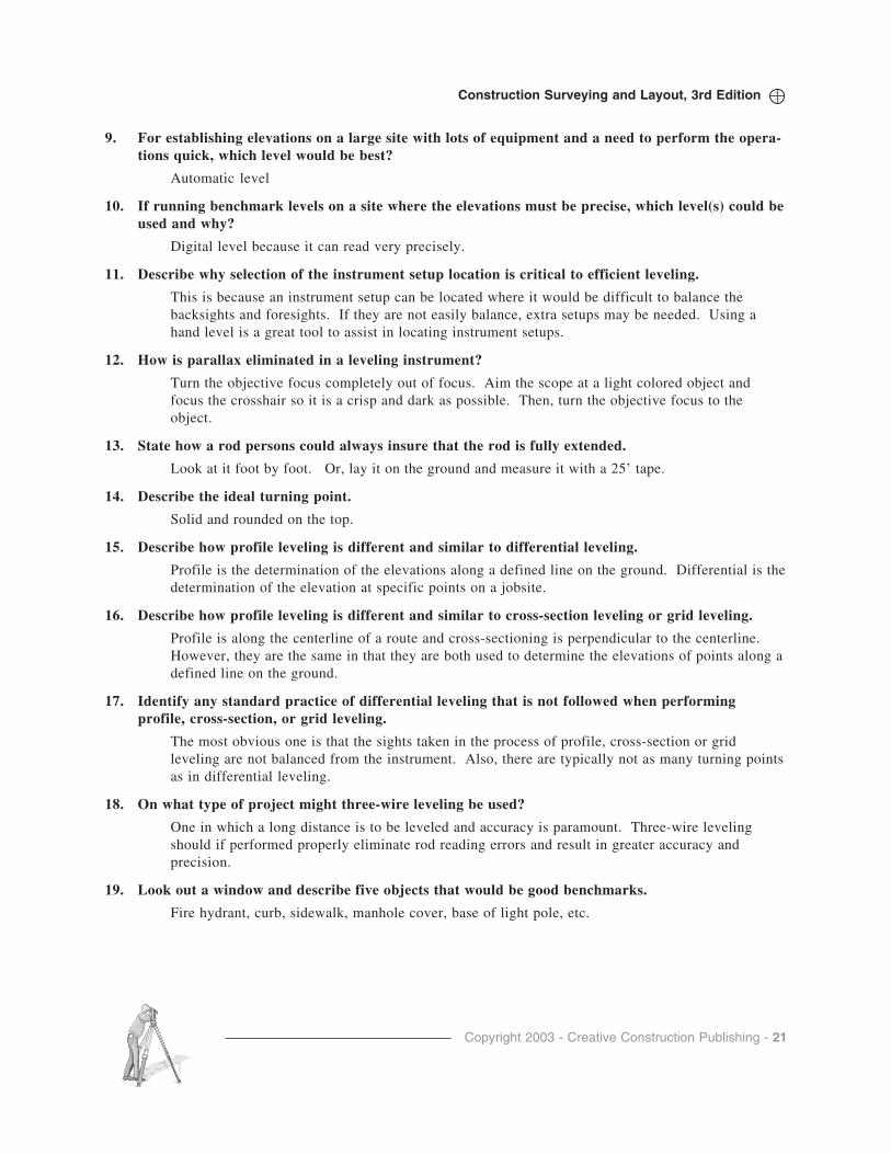
STEP 4 - Hold the rod on the turning point and read and record the foresight reading.
STEP 5 - Repeat previous steps until the elevation of the designated point has been determined.
STEP 6 - Close the loop by repeating the process back to the benchmark.
7. State why the distance from the instrument to the backsight and the instrument to the foresightmust be the same. (Balanced)
If there is an error in the line of sight causing it not to be horizontal, making sure the distance fromthe instrument to the Backsight and the distance from the instrument to the forsight is the same(balanced) will result in this error being canceled. In other words, the error would be added inwith the backsight and and equal error would be subtracted out with the forsight if the line of sightis not horizontal. If they are not balanced, the errors will not be the same and they will not cancel.
8. For leveling on a small construction site such as a home, which type of level would be a goodchoice to establish the footing elevations with?
Builders level
Copyright 2003 - Creative Construction Publishing - 21
Construction Surveying and Layout, 3rd Edition
9. For establishing elevations on a large site with lots of equipment and a need to perform the opera-tions quick, which level would be best?
Automatic level
10. If running benchmark levels on a site where the elevations must be precise, which level(s) could beused and why?
Digital level because it can read very precisely.
11. Describe why selection of the instrument setup location is critical to efficient leveling.
This is because an instrument setup can be located where it would be difficult to balance thebacksights and foresights. If they are not easily balance, extra setups may be needed. Using ahand level is a great tool to assist in locating instrument setups.
12. How is parallax eliminated in a leveling instrument?
Turn the objective focus completely out of focus. Aim the scope at a light colored object andfocus the crosshair so it is a crisp and dark as possible. Then, turn the objective focus to theobject.
13. State how a rod persons could always insure that the rod is fully extended.
Look at it foot by foot. Or, lay it on the ground and measure it with a 25’ tape.
14. Describe the ideal turning point.
Solid and rounded on the top.
15. Describe how profile leveling is different and similar to differential leveling.
Profile is the determination of the elevations along a defined line on the ground. Differential is thedetermination of the elevation at specific points on a jobsite.
16. Describe how profile leveling is different and similar to cross-section leveling or grid leveling.
Profile is along the centerline of a route and cross-sectioning is perpendicular to the centerline.However, they are the same in that they are both used to determine the elevations of points along adefined line on the ground.
17. Identify any standard practice of differential leveling that is not followed when performingprofile, cross-section, or grid leveling.
The most obvious one is that the sights taken in the process of profile, cross-section or gridleveling are not balanced from the instrument. Also, there are typically not as many turning pointsas in differential leveling.
18. On what type of project might three-wire leveling be used?
One in which a long distance is to be leveled and accuracy is paramount. Three-wire levelingshould if performed properly eliminate rod reading errors and result in greater accuracy andprecision.
19. Look out a window and describe five objects that would be good benchmarks.
Fire hydrant, curb, sidewalk, manhole cover, base of light pole, etc.

Copyright 2003 - Creative Construction Publishing - 22
Construction Surveying and Layout, 3rd Edition
20. Calculate the following differential leveling notes. Provide an arithmetic check.
Difference between starting and ending elevation = 1420.520 – 1420.526 = 0.006
Difference between Sum of BS and Sum of FS = 39.856 – 39.850 = 0.006 Checks
Level Loop from BM Birch to BM Moose
Station +BS HI -FS -SS Elevation
BM Birch 1420.520
Inst. 6.113 1426.633
TP # 1 7.188 1419.445
Inst 5.776 1425.221
TP # 2 4.324 1420.897
Inst 6.734 1427.631
BM Moose 9.717 1417.914
Return
BM Moose 1417.914
Inst 9.586 1427.500
TP # 3 10.417 1417.083
Inst. 11.647 1428.73
BM Birch 8.204 1420.526
Check Σ = 39.856 39.850
Copyright 2003 - Creative Construction Publishing - 23
Construction Surveying and Layout, 3rd Edition
Level Loop from BM 338 to BM 441
Station +BS HI -FS -SS Elev
BM 338 6.659 241.772 235.113m
TP # 1 5.431 241.086 6.117 235.655
TP # 2 5.135 237.487 8.734 232.352
TP # 3 5.321 233.657 9.151 228.336
TP # 4 3.197 224.898 11.956 221.701
TP # 5 0.355 214.486 10.767 214.131
BM 441 11.772 217.880 8.378 206.108
TP # 6 12.919 225.348 5.451 212.429
TP # 7 14.185 231.757 7.776 217.572
TP # 8 12.717 232.877 11.597 220.160
TP # 9 10.239 232.345 10.771 222.106
TP # 10 9.636 236.854 5.127 227.218
BM 338 1.736 235.118
Check 97.566 97.561
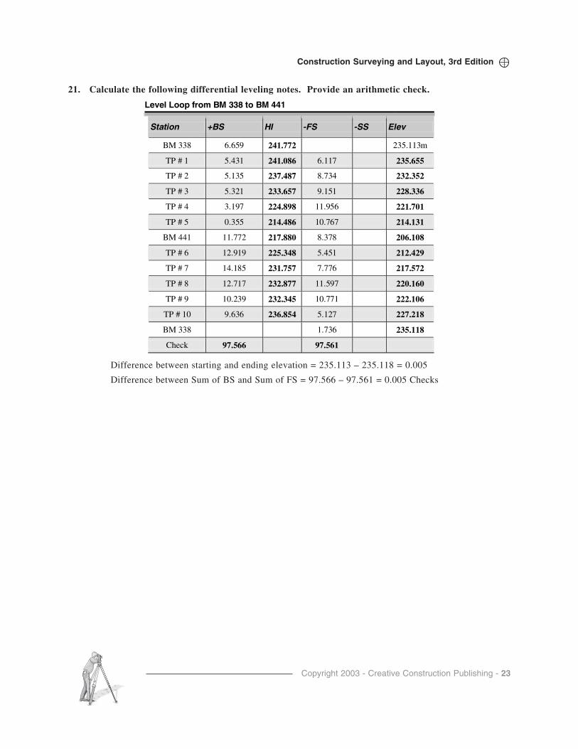
21. Calculate the following differential leveling notes. Provide an arithmetic check.
Difference between starting and ending elevation = 235.113 – 235.118 = 0.005
Difference between Sum of BS and Sum of FS = 97.566 – 97.561 = 0.005 Checks
Copyright 2003 - Creative Construction Publishing - 24
Construction Surveying and Layout, 3rd Edition
Profile Level Notes of Barcus Orchard Road
Station +BS HI -FS -SS Elev
BM 3055 4.56 4414.580 4410.02
TP # 1 2.43 4407.690 9.32 4405.260 0+00 4.6 4403.1
0+50 4.2 4403.5
1+00 3.2 4404.5
1+50 1.7 4406.0
TP # 2 5.68 4412.48 0.89 4406.800
2+00 7.5 4405.0
2+50 3.8 4408.7
2+76 6.5 4406.0
3+00 2.7 4409.8
Tp # 3 3.75 4413.53 2.70 4409.78
TP # 4 7.62 4415.49 5.66 4407.87
BM 3055 5.45 4410.04
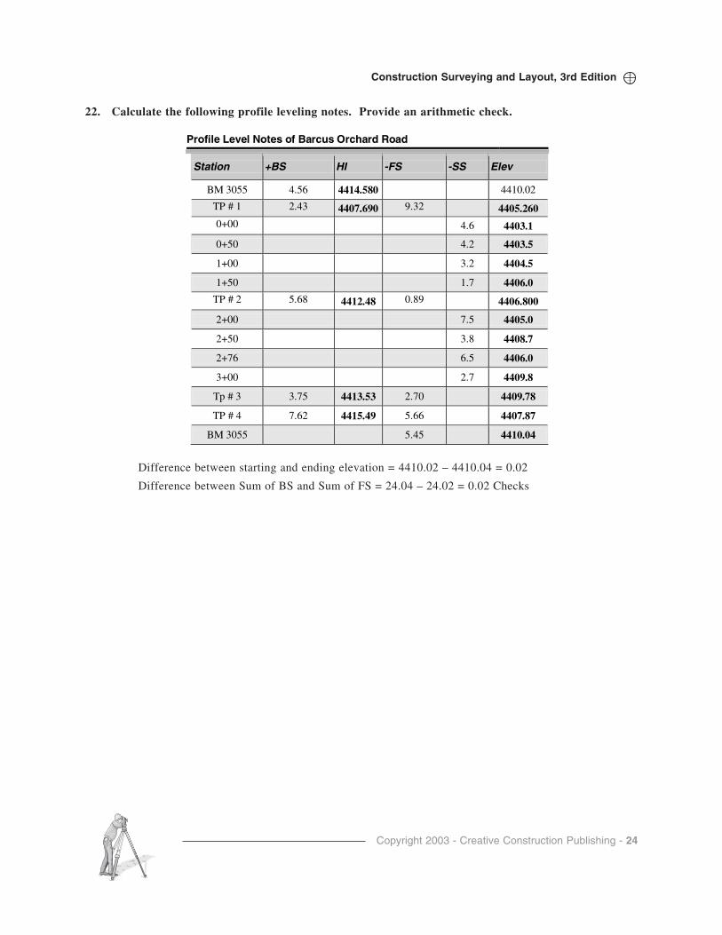
22. Calculate the following profile leveling notes. Provide an arithmetic check.
Difference between starting and ending elevation = 4410.02 – 4410.04 = 0.02
Difference between Sum of BS and Sum of FS = 24.04 – 24.02 = 0.02 Checks

Copyright 2003 - Creative Construction Publishing - 25
Construction Surveying and Layout, 3rd Edition
23. Calculate the following profile leveling notes. Provide an arithmetic check.
Profile Level Notes of Camp Rotary Road
Station +BS HI -FS -SS Elev
BM 325 2.562 443.582 441.02m
TP # 1 2.430 442.179 3.833 439.749
0+00 4.63 437.55
0+20 5.23 436.95
0+40 3.82 438.36
0+55 1.75 440.43
1+45 0.54 441.64
Tp # 2 3.958 443.367 2.770 439.409
1+50 1.82 441.55
2+76 3.65 439.72
3+00 4.79 438.58
TP # 3 3.621 441.352 5.636 437.731
BM 325 0.336 441.016
BS + FS 12.571 12.575
Difference between starting and ending elevation = 441.02 – 441.016 = 0.004
Difference between Sum of BS and Sum of FS = 0.004 Checks.
Copyright 2003 - Creative Construction Publishing - 26
Construction Surveying and Layout, 3rd Edition
Elevations of XYZ Building Site Prior to Excavation
Station +BS HI -FS -SS Elev
BM 926 1.75 622.03 620.28
TP1 3.44 620.91 4.56 617.47
A1 4.7 616.2
A2 4.6 616.3
A3 4.5 616.4
A4 4.4 616.5
B1 5.2 615.7
B2 5.0 615.9
B3 5.0 615.9
B4 4.7 616.2
C1 5.6 615.3
C2 5.2 615.7
C3 4.8 616.1
C4 4.5 616.4
D1 5.8 615.1
D2 5.1 616.8
D3 4.8 616.1
D4 4.6 616.3
TP 2 5.67 622.88 3.70 617.21
BM 926 2.59 620.29
BS + FS 10.86 10.85
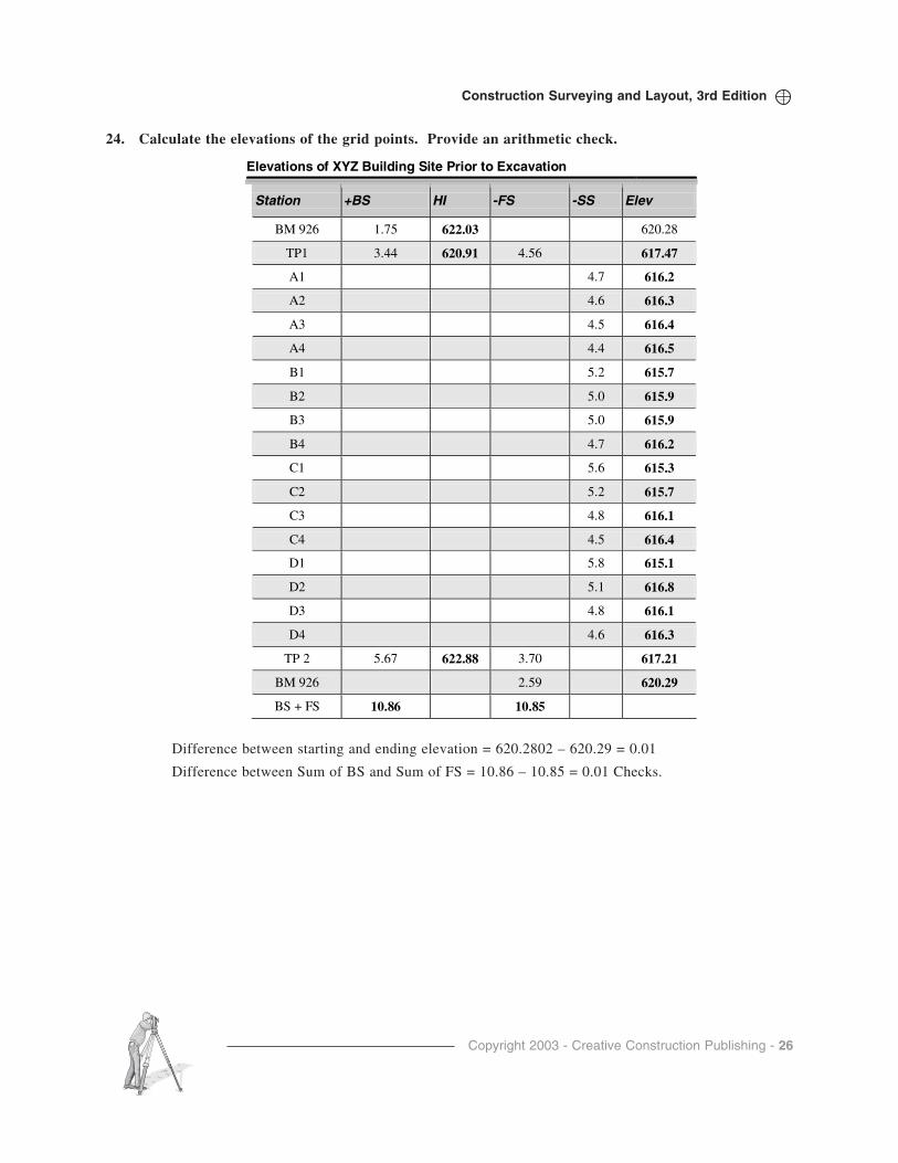
24. Calculate the elevations of the grid points. Provide an arithmetic check.
Difference between starting and ending elevation = 620.2802 – 620.29 = 0.01
Difference between Sum of BS and Sum of FS = 10.86 – 10.85 = 0.01 Checks.
Copyright 2003 - Creative Construction Publishing - 27
Construction Surveying and Layout, 3rd Edition
Elevations of XYZ Building Site after Excavation
Station +BS HI -FS -SS Elev
BM 926 2.59 622.87 620.28
TP1 4.44 621.63 5.68 617.19
A1 9.7 611.9
A2 9.6 611.3
A3 9.6 611.3
A4 9.7 611.9
B1 9.7 611.9
B2 9.6 612.0
B3 9.5 612.1
B4 9.7 611.9
C1 9.8 611.8
C2 9.6 611.3
C3 9.7 611.9
C4 9.8 611.8
D1 9.7 611..9
D2 9.6 611.3
D3 9.8 611.8
D4 9.7 611.9
TP 2 3.83 3.71 617.92
BM 926 1.49 620.26
BS + FS 10.86 10.88
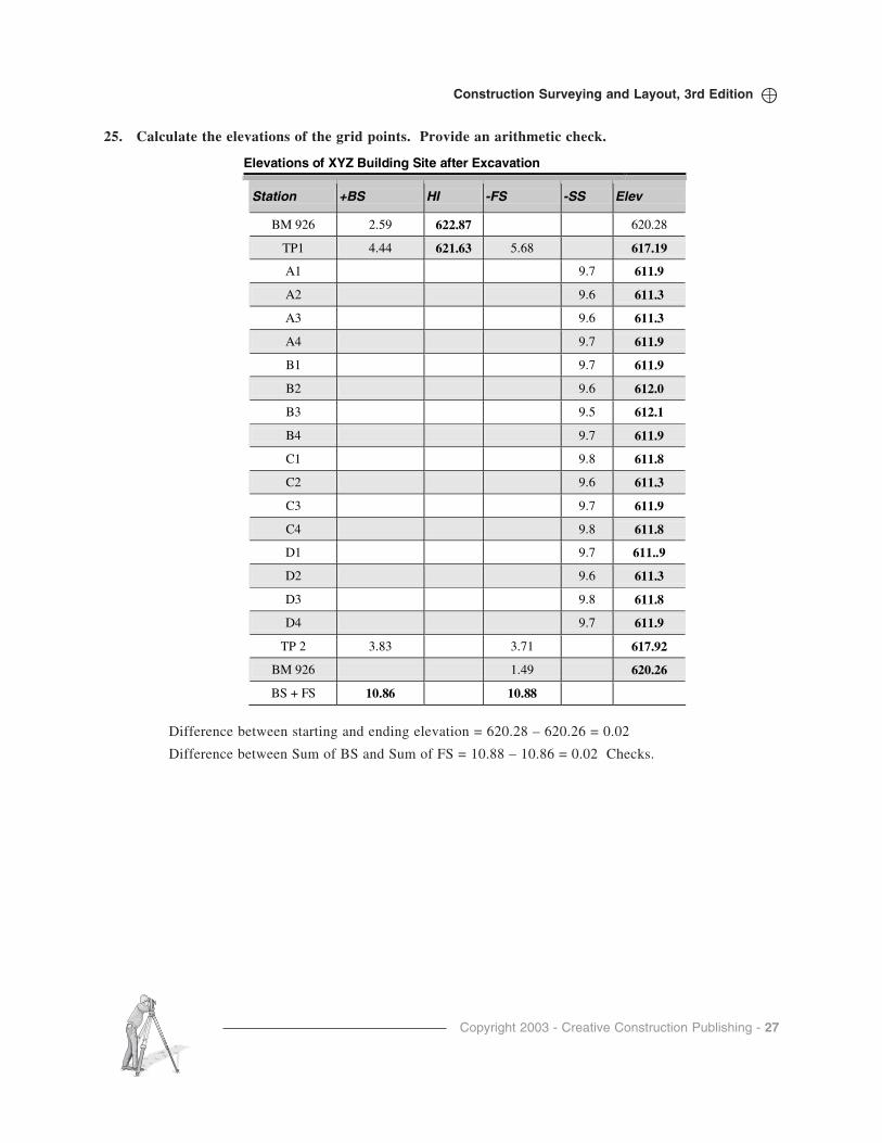
25. Calculate the elevations of the grid points. Provide an arithmetic check.
Difference between starting and ending elevation = 620.28 – 620.26 = 0.02
Difference between Sum of BS and Sum of FS = 10.88 – 10.86 = 0.02 Checks.

Copyright 2003 - Creative Construction Publishing - 28
Construction Surveying and Layout, 3rd Edition
26. The grade foreman on the utilities just called. He doesn’t like decimal parts of a foot representedon grade stakes. He wants the offset stake tops to be a whole number of feet (XXX.00) abovefoundation forms. Having gathered the following data, how much deeper must this stake bedriven until it is a whole number of feet above the form elevation of 658.00? What elevation is itdriven to? When the stake is at the desired grade, what will be your reading on the rod?
Top of Form = 658.0'
BM #1= 664.71 BM #2 = 665.32
BS on BM #1 =7.23 BS on BM #2 = 6.62
Initial Rod Reading on Stake = 11.34
Answer:
HI#1 = 664.71 + 7.23 = 671.94
HI#2 = 665.32 + 6.62 = 671.94
This confirms that the Benchmarks have not moved, the readings were correct, and the math wascorrect. The HI is 671.94.
HI - Rod Reading = Elevation on Stake.
671.94 - 11.34 = 660.60.
660.60 - 658.00 = 2.60' above the form elevation.
To get the mark on the stake an even number of feet above 658.00, drive the stake 0.60' down sothat the rod reading on the stake will be
11.34 + 0.60 = 11.94.
Checking...671.94 - 11.94 = 660.00. The stake is exactly 2 feet above the formwork and has beendriven to elevation 660.00.

Copyright 2003 - Creative Construction Publishing - 29
Construction Surveying and Layout, 3rd Edition
Chapter 8 - Lasers
QUESTIONS AND PROBLEMS
1. What is LASER an acronym for?
Light Amplified by Stimulated Emission of Radiation
2. List advantages of lasers as a construction tool.
Ease of use, productivity, versatility, fewer human errors, accurate, dependable.
3. Explain why lasers are so versatile.
Many kinds, horizontal lines, horizontal planes, vertical lines, vertical planes, slope lines, slopeplanes and compound planes are possible with various types of lasers.
4. What benefits do lasers bring to the construction site?
Manny applications of the laser are possible on the construction site. See answers above.
5. What types of lasers are available?
Visible beam and electronic levels.
6. Distinguish between fixed, rotating, and utility lasers.
A fixed laser projects a single line, for example a pipe laser.
A rotating laser projects a beam that can be seen 360º around the instrument.
A utility laser projects fixed or rotating lines.
7. List the various classes of lasers and their accuracy.
Fixed = + 1/16th per 100 feet.
Rotating = + 1/16th per 100 feet
Utility = + 1/16th per 100 feet.
8. List five uses of a pocket laser on a jobsite.
• Square a room
• Project a line onto a ceiling
• Create a horizontal line
• Project a straight line
• Locate the center of a room, etc.
9. Describe why a utility laser is such a versatile instrument.
Utility has all the functions and planes available on it.
10. Explain why having two or more lasers set up on a construction site could cause major mistakes.
Two planes could be projected and the wrong line could be picked up by a sensor.

Copyright 2003 - Creative Construction Publishing - 30
Construction Surveying and Layout, 3rd Edition
11. List five sources of mistakes that could occur in laser use on the jobsite.
• Two lasers used at the same time
• Signal reflection off of a surrounding building
• Laser bumped
• Weather deflection of line
• Wrong Benchmark used
12. Under what conditions might a laser become unusable due to weather.
Heavy rain, fog, snow
13. Besides a normal level rod, what can a sensor be attached to when establishing elevations?
Direct elevation rod, 2 by 2 lumber, 2 by 4 lumber
14. Describe how it is possible to establish grade (elevations) with one person, using a direct elevationrod and Laser
Set BM elevation at the line of sight of the laser on the rod. Read elevations of FS onto TurningPoint directly on the rod. Repeat as needed for each instrument setup. This is time-consuming,but it is do-able by one person.
15. What type of laser does not have to be checked for calibration?
None. All should be checked.
Chapter 9 - GPS Field Procedures
QUESTIONS AND PROBLEMS
1. What makes GPS unique from other measuring tools?
It determines position via satellite signals. No physical measurement (such as chaining) is madebetween points.
2. In what ways has GPS revolutionized surveying?
One person surveys are possible. Position can be determined anywhere on the surface of the earth.Intervisibility between points is not needed, etc.
3. List 5 uses of GPS other than those listed in this text.
• Farming
• GEOCACHE games
• Military
• Ship navigation
• Mountain climbing, etc.
4. How many satellites are used in the GPS system?
24 plus 6 in reserve
Copyright 2003 - Creative Construction Publishing - 31
Construction Surveying and Layout, 3rd Edition
5. List 5 advantages of GPS over conventional surveying techniques.
• Intervisibility not needed
• Instant positioning
• Day or night use
• Flexibility
• Simple operation.
6. Describe 5 significant disadvantages of GPS.
• Obstacles such as trees, buildings
• Satellite positioning limits time and day for strongest signals
• No underground system
• Can’t be used under bridges
• Battery dependent, etc
7. Why isn’t GPS used for all types of surveying and construction layout?
Not precise enough for all types of layout.
8. Research in a library or on the Internet the different types of GPS surveying (static, rapid static,kinematic, stop and go, and RTK) and their uses in surveying.
Please visit the library for this answer.
9. Describe the basic theory of DGPS.
Establish a GPS base station that communicates with a rover GPS unit. The difference betweenpositions can be very accurately determined.
10. Identify why good GPS surveying starts in the office and not in the field.
Planning must be the first step of a GPS survey. Determine the location, time, obstacles, obstruc-tions, etc., to make system work as efficiently as possible.
11. List 10 standard practices that will improve the field procedures of GPS surveys.
• Consistancy • Flexibility • Checklists of equipment
• Planning • Reconnaissance • GDOP
• Reception • Orientation • Security
• Calibration • Checklists of personal equipment
12. On a word processor, develop your own personal checklists for GPS surveying.
This is a personal list.
13. What is the most important part of GPS planning?
Availability of satellites.
14. Based on the items discussed in this Chapter, go to a local construction site and prepare a skyplotof obstructions that would affect GPS work on that site.
Personal observations.

Copyright 2003 - Creative Construction Publishing - 32
Construction Surveying and Layout, 3rd Edition
15. Prepare a checklist that could be used to check all of the equipment used in a GPS survey toensure that it is in good shape.
This could be done in a table on a word processor. The answer is dependent on the type of equip-ment available.
16. Visit the World Wide Web and locate websites that present GPS satellite availability times foryour location.
Personal observation of WWW resources.
17. Distinquish between the various DOP’s that affect the GPS survey results.
PDOP – precision in position
HDOP – horizontal position
GDOP – Geometric position of satellites
VDOP – Vertical position
18. Locate a local baseline for calibrating GPS equipment.
Personal observation in your area.
19. Develop a GPS log sheet for recording the observation data.
20. What is the most important rule of thumb regarding the downloading of GPS data?
Back it up. Download as soon as possible.
1 2 3 4 5 6 7 8 9 10
11 12 13 14 15 16 17 18
19 20 21 22 23 24 25 26
27 28 29 30
Project Name: Project ID:Company:Crew:Date: Day: Start Time: End Time:Weather: Temp: Pressure:Station Name: ID: #Equipment: Observer:Model: Antenna: Fixed or VariableReceiver S/N: HI of Fixed Pole:Antenna S/N: Satellites Tracked: CircleAntenna Model: Data Collector S/N: Tripod Type: Fixed Adjustable Cable Condition Lengths File Name Backup Yes No Sketch on Back? Yes No Problems Encountered:

Copyright 2003 - Creative Construction Publishing - 33
Construction Surveying and Layout, 3rd Edition
Chapter 10 - Equipment Calibration
QUESTIONS AND PROBLEMS
1. Describe what the components of an ideal area would be for testing angle-measuring instruments.
Avoid obstacles, flat, open area
2. Describe what an ideal area for testing leveling instruments.
Flat open area for testing leveling equipment
3. When is the best time of the day to perform calibration checks?
Early morning before the sun comes up and the air temperature becomes hot.
4. Describe the step-by-step process used to calibrate a chain.
STEP 1 - Assign specific duties to the individuals assisting in the test: Two persons to hold the ends ofthe chains and apply the proper tension, one person to align the 0 ends, and one person to makethe comparison at the 100- or 200-foot ends. Lay out the chains. Attach the tension handles to thechains. Assuming the chains will be lying on the ground fully supported, a tension of 10-12pounds will be applied. (Check chain manufacturer for the exact tension required for the particularchain.) The persons doing the comparing should each have a magnifying glass for more precisealignment of the end marks.
STEP 2 - With everyone in position, apply tension to the chains. Have the person at the 0 end commu-nicate to the holders to align the 0’s perfectly. When that is ready, communicate to the personmeasuring the difference between the calibrated chain and the chain being tested. Constantcommunication between the participants is the key to a successful comparison of the chains.
STEP 3 - The person doing the comparison should measure and record the difference (estimate to thethousandth of a foot) between the ends of the chains.
STEP 4 - Repeat the test at least three times to obtain an average of the difference in length. Apply anycorrection for expansion or contraction of the chain because of temperature. Compare the nominal(what length the chain should be) to the calibrated length.
5. Draw an instrument and show the principle lines and geometric relationships.
See text on page 10-11.Vertical
Axis
Horizontal
AxisAxis ofLevel Tube
Line of Sight
VerticalCrosshair
HorizontalCrosshair
Copyright 2003 - Creative Construction Publishing - 34
Construction Surveying and Layout, 3rd Edition
6. What out-of-calibration geometric relation is not eliminated by direct-and-reverse procedures?
Plate level not being perpendicular to the vertical axis.
7. When prolonging a centerline on a highway project, which geometric relationship is most impor-tant?
Line of sight should be perpendicular to the horizontal axis.
8. In high-rise construction, which of the geometric relationships within an instrument is mostimportant for plumbing the structure?
The horizontal axis should be perpendicular to the vertical axis.
9. When using a transit as a level for setting grade on forms, establishing elevation, etc., which of thegeometric relationships within an instrument is most important?
The line of sight should be perpendicular to the vertical axis.
10. What special procedure must be performed so that the quick peg can be performed by one person?Describe or illustrate.
STEP 1 - Locate two objects that are about 250 feet apart where it would be possible to glue onto or nailinto a 2-foot or 1-meter section of an old rod. This could be old power poles, light poles, build-ings, bridge piers, etc. Obtain permission to do this from the owner.
STEP 2 - Set up the leveling instrument exactly between these two objects, make sure it is level, andsight towards each object and mark the line of sight on the object. Because of the geometry of theinstrument, these marks will be the same elevation.
STEP 3 - Glue or nail a section of rod on each object, making sure the foot or meter mark at the bottomof the rod is exactly on the marks placed on the object.
STEP 4 - Now, whenever a leveling instrument needs to be pegged, simply set up the instrument closeto one of the objects. Sight onto the near rod face, and read the rod. Sight onto the far rod face,and read the rod.
STEP 5 - Compare the readings. Ignore the whole foot/meter parts of the reading as they may not be thesame since a different part of the rod was glued to the object. However, the decimal part of thereading should be the same if the instrument is in proper adjustment. If the decimal parts aredifferent, the instrument needs adjusted.
11. Describe how to check the calibration of a circular bubble.
STEP 1 - Screw the prism pole into the top assembly. Place prism pole tip in bottom shoe. Move thebrackets as needed to center the bubble. Tighten the top and bottom.
STEP 2 - Now rotate or spin prism pole 360°. If the bubble is in adjustment, it will remain centeredthroughout this rotation. If the bubble drifts off of center, the bubble is not in adjustment.
STEP 3 - If the bubble needs adjustment, locate the vial adjustment screws on the bottom of the bubblehousing, and turn them until the bubble is centered.
Repeat Step 2 until bubble remains centered in a full 360-degree rotation.