solutions for 802.11p wireless access in vehicular environments...
TRANSCRIPT

Keysight TechnologiesSolutions for 802.11p Wireless Access in Vehicular Environments (WAVE) Measurements
Application Note
02 | Keysight | Solutions for 802.11p Wireless Access in Vehicular Environments (WAVE) Measurements - Application Note
Accelerating Design and Test of 802.11p Devices for the Connected Car Using A Range of Flexible, High-Performance SolutionsOverviewOne of the critical issues facing society today is automotive safety. According to figures released by the World Health Organization (WHO), approximately 2,500 people are killed on roads every day, which equates to nearly 1 million people each year. Automotive companies have recognized their role in this challenge and are now proactively working to adapt to new technologies designed to improve road safety and reduce the incidence of accidents that cause death and injury on the road. Using advanced wireless communi-cations, these companies will improve car safety for drivers, passengers, pedestrians and others. At the same time, they will provide a slew of other benefits, ranging from better traffic management, improved energy efficiency and updated in-car entertainment/information systems. All of these benefits will be delivered though connected car technologies.
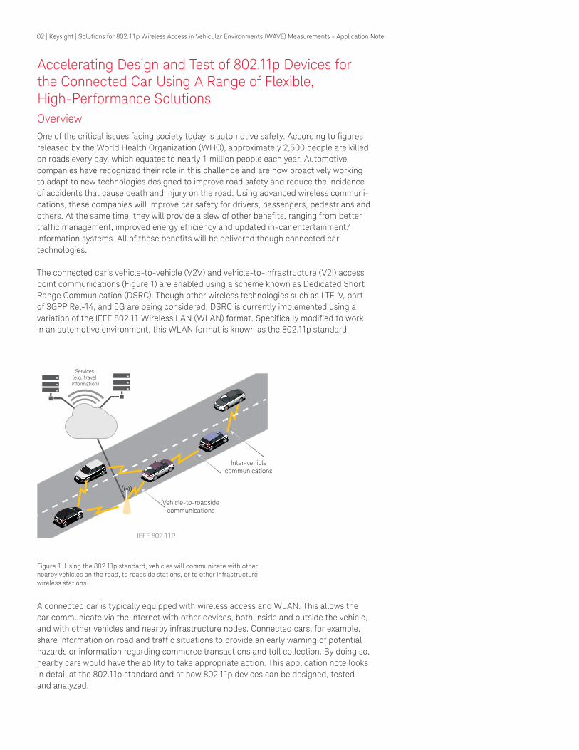
The connected car’s vehicle-to-vehicle (V2V) and vehicle-to-infrastructure (V2I) access point communications (Figure 1) are enabled using a scheme known as Dedicated Short Range Communication (DSRC). Though other wireless technologies such as LTE-V, part of 3GPP Rel-14, and 5G are being considered, DSRC is currently implemented using a variation of the IEEE 802.11 Wireless LAN (WLAN) format. Specifically modified to work in an automotive environment, this WLAN format is known as the 802.11p standard.
Services (e.g. travel information)
Vehicle-to-roadsidecommunications
IEEE 802.11P
Inter-vehiclecommunications
Figure 1. Using the 802.11p standard, vehicles will communicate with other nearby vehicles on the road, to roadside stations, or to other infrastructure wireless stations.
A connected car is typically equipped with wireless access and WLAN. This allows the car communicate via the internet with other devices, both inside and outside the vehicle, and with other vehicles and nearby infrastructure nodes. Connected cars, for example, share information on road and traffic situations to provide an early warning of potential hazards or information regarding commerce transactions and toll collection. By doing so, nearby cars would have the ability to take appropriate action. This application note looks in detail at the 802.11p standard and at how 802.11p devices can be designed, tested and analyzed.
03 | Keysight | Solutions for 802.11p Wireless Access in Vehicular Environments (WAVE) Measurements - Application Note
Problem
Applying advanced technologies like 802.11p offers enormous benefits for the automotive industry, but it also presents new design and test challenges for developers and manufacturers. Vehicles with 802.11p will communicate with other vehicles and roadside infrastructure, sharing information regarding location, speed, acceleration, and even anti-lock braking system activation. They’ll also share more mission-critical road and traffic condition information; regardless of whether or not they are visible to one other or around a blind curve.
To ensure a robust 802.11p system, accurate physical layer tests are essential. One of the specific challenges associated with testing 802.11p-based devices is being able to properly generate the waveforms needed for receiver measurement, with fading as necessary. When measuring the transmitter, dealing with the much stricter spectrum emission mask, transmitter power and more, can also be problematic.
What’s required to overcome these challenges is an effective test and measurement strategy for 802.11p devices; one that enables appropriate signal generation and analysis to properly test and measure communication links (e.g., the transmitter and receiver). The signal generation and analysis solutions utilized should offer fast measurement times and switching speeds, scalability to allow the tools to be tailored to the users changing test needs, and flexibility to ensure they support both current and future formats.

04 | Keysight | Solutions for 802.11p Wireless Access in Vehicular Environments (WAVE) Measurements - Application Note
Solution
To better understand the solutions for overcoming the challenges that come with implementation of 802.11p in automotive applications, it’s first necessary to have a clearer understanding of the standard itself. First published as an amendment in 2010, 802.11p is part of the 802.11-2012 Wireless LAN standard, and is targeted as the PHY and MAC layers of a vehicular communication system known as Wireless Access in Vehicular Environments (WAVE). The standard defines enhancements to 802.11 to support Intelligent Transportation System (ITS) applications. This includes data exchange between high-speed vehicles, as well as between the vehicles and roadside infrastructure in the licensed 5.9 GHz (5.85-5.925 GHz) ITS band. While details of the ITS system (especially at higher layers) will vary depending on regional issues, these systems plan to use 802.11p for the MAC and physical (PHY) layers. Devices based on the 802.11p standard can be used in environments where the PHY properties are rapidly changing and very short-duration communication exchanges are required.
The 802.11p standard defines three modes: 5-, 10- and 20-MHz, and utilizes the same PHY as the 802.11a standard; however, the 802.11p PHY has a different sampling rate. Table 1 shows the differences between the 802.11a and 802.11p PHY layer specifications. Note that a few modifications for the PHY and MAC are needed in 802.11p to achieve a robust connection and a fast setup for a moving vehicle environment. Table 1. 802.11a and 802.11p physical layer specifications.
Comparison of Physical Parameters Between 802.11a and 802.11p Standards
Parameters 802.11a 802.11p
Channel bandwidth 20 MHz 5, 10 , 20 MHz
Bit rate (Mbps) 6, 9, 12, 18, 24, 36, 48, 54 1.5, 2.25, 3, 4.5, 6, 9, 12, 13.5 18, 24, 27, 36, 48, 54
Modulation type BPSK, QPSK, 16QAM, 64QAM BPSK, QPSK, 16QAM, 64QAM
Code rate 1/2, 2/3, 3/4 1/2, 2/3, 3/4
Number of subcarriers 52 52
Symbol duration 4 µs 16, 8, 4 us
Guard time 0.8 µs 3.2,1.6, 0.8 µs
Preamble duration 16 µs 64, 32, 16 µs
Subcarrier spacing 312.5 kHz 78.125, 156.25, 312.5 kHz
SEM Fixed IEEE and regional FCC, ETSI

05 | Keysight | Solutions for 802.11p Wireless Access in Vehicular Environments (WAVE) Measurements - Application Note
Test Requirements for 802.11p Measurements
Whether for the purposes of research and development, production test, quality assurance, or regulatory testing, measurement of the PHY layers of 802.11p devices is absolutely necessary. These measurements fall into two distinct categories: 802.11p transmitter and receiver tests.
802.11p Transmitter Tests 802.11p transmitter measurements are needed to analyze the physical parameters of the 802.11p signal generated from a Device-under-Test (DUT) to verify its transmit characteristics and the required standards including channel power, occupied bandwidth, spectrum emission mask (SEM), center frequency, symbol clock tolerance, and modulation accuracy.
Table 2 summarizes test requirements for the 802.11a and 802.11p standards. Some 802.11p test requirements are the same as those for 802.11a (e.g., spectral flatness and constellation error), but others were specifically defined for 802.11p. Besides the 802.11p test requirements defined in 802.11, regional test requirements (e.g., the Federal Communications Commission (FCC) in the United States and the European Telecommunications Standards Institute (ETSI) in Europe) are also required.
The test requirements specifically defined for 802.11p include:
Transmitter Power. The 802.11-2012 Annex D.2.2 specification defines four different power classes: A, B, C, and D (Table 3).
Table 2. 802.11a and 802.11p transmitter test requirements.
Transmitter Test 802.11a IEEE-2012
802.11p IEEE-2012
Transmitter power 18.3.9.2 IEEE 802.11: Annex D.2.2FCC: 47 CFR[B8] Sec. 90.375ETSI 302 571 Sec. 6.3
Spectrum mask 18.3.9.3 IEEE 802.11: Annex D.2.3FCC: 47 CFR [B8] Sec. 95.377ETSI: 302571 Sec 6.4
Transmission spurious 18.3.9.4 Same as 802.11a
Center frequency tolerance 18.3.9.5 ±20 ppm for 20 MHz/10MHz±10 ppm for 5 MHz
Symbol clock frequency tolerance 18.3.9.6 ±20 ppm for 20 MHz/10MHz±10 ppm for 5 MHz
Center frequency leakage 18.3.9.7.2 Same with 802.11a
Spectral flatness 18.3.9.7.3 Same with 802.11a
Constellation error 18.3.9.7.4 Same with 802.11a
Modulation accuracy 18.3.9.8 Same with 802.11a
Table 3. Four different power classes are defined in 802.11-2012 standard Annex D.2.2.
Power Class Max. Output Power (dBm)
Class A 0
Class B 10
Class C 20
Class D 28.8

06 | Keysight | Solutions for 802.11p Wireless Access in Vehicular Environments (WAVE) Measurements - Application Note
Specifically, the SEM test requirements for 802.11p power classes C and D are much stricter than for 802.11a (Figure 2).
Transmit center frequency and symbol clock frequency tolerance. The 802.11-2012 specification defines the transmit center frequency and symbol clock frequency tolerance for different bandwidths. The test requirements are as follows:
– A transmitted center frequency tolerance of ±20 ppm maximum for 20- and 10-MHz channels, and ±10 ppm maximum for 5-MHz channels. The transmit center frequency and symbol clock frequency must be derived from the same reference oscillator.
– A symbol clock frequency tolerance of ±20 ppm maximum for 20- and 10-MHz channels, and ±10 ppm maximum for 5-MHz channels. The transmit center frequency and symbol clock frequency must be derived from the same reference oscillator.
SEM. Annex D.2.3 defines the SEM for operations in the United States (Table 4). In addition, SEMs are also defined by the FCC and ETSI for local test requirements.
Table 4. SEM data for 802.11p 10-MHz channel spacing in 802.11-2012 Annex D.2.3
STA Transmit Power Class
Permitted power spectral density, dBr
± 4.5-MHz Offset (± f1) ± 5.0-MHz Offset (± f2) ± 5.5-MHz Offset (± f3) ±10-MHz Offset (± f4) ±15-MHz Offset (± f5)
Class A 0 -10 -20 -28 -40
Class B 0 -16 -20 -28 -40
Class C 0 -26 -32 -40 -50
Class D 0 -35 -45 -55 -65
802.11p SEM for 10 MHz Signal Bandwidth Power Class APower Class CIEEE Normal
Power Class BPower Class D
Figure 2. 802.11p SEM test requirements for IEEE and power class A-D for 10 MHz

07 | Keysight | Solutions for 802.11p Wireless Access in Vehicular Environments (WAVE) Measurements - Application Note
Table 6. Receiver minimum input sensitivity test requirement for the 802.11p standard.
Modulation Coding Rate 5-MHz Channel Spacing
10-MHzChannel Spacing
20-MHzChannel Spacing (Same as 802.11a)
BPSK 1/2 -88 -85 -82
BPSK 3/4 -87 -84 -81
QPSK 1/2 -85 -82 -79
QPSK 3/4 -83 -80 -77
16QAM 1/2 -80 -77 -74
16QAM 3/4 -76 -73 -70
64QAM 2/3 -72 -69 -66
64QAM 3/4 -71 -68 -65
802.11p Receiver Tests Table 5 summarizes test requirements for 802.11a and 802.11p. Note that some 802.11p receiver test requirements are the same as those for 802.11a. However, 802.11p defines much stricter requirements for adjacent and nonadjacent channel rejection.
Table 5. 802.11a and 802.11p receiver test requirements.
ReceiverTest 802.11a IEEE-2012
802.11p IEEE-2012
Minimum input sensitivity 18.3.10.2 Sensitivity for 5 MHz and 10 MHz20 MHz is same with 802.11a
Adjacent channel rejection 18.3.10.3 12 dB stricter than 802.11a
Non-adjacent channel rejection 18.3.10.4 10 dB stricter than 802.11a
Maximum input level 18.3.10.5 Same with 802.11a
Clear channel assessment 18.3.10.6 -82 dBm for 20 MHz-85 dBm for 10 MHz-88 dBm for 5 MHz
Received channel power indicator measurement
18.3.10.7 Same with 802.11a
The 802.11p receiver test requirements include:
Receiver minimum input sensitivity. This receiver test measures the sensitivity of the DUT at the condition of very low input levels. The minimum test requirement for sensitivity levels depends on the modulation and channel bandwidth. Table 6 shows the 802.11p test requirements for receiver minimum input sensitivity at 5-, 10- and 20-MHz channel spacing.

08 | Keysight | Solutions for 802.11p Wireless Access in Vehicular Environments (WAVE) Measurements - Application Note
Adjacent and non-adjacent channel rejection. Adjacent and non-adjacent channel rejection are key 802.11p receiver tests. They are measured by setting the desired signal’s strength to 3 dB above the rate dependent sensitivity specified in Table 7, and raising the power of the interfering signal until 10 percent packet error rate (PER) results. The power difference between the interfering and desired channel is the corresponding adjacent or nonadjacent channel rejection. Note that the requirements for these tests are very strict because 802.11p is much more sensitive to interference in the adjacent or non-adjacent channel.
Table 7. This table summarizes the adjacent or non-adjacent channel rejection test requirements for 802.11p
Modulation Coding Rate Adjacent Channel Rejection(dB)(802.11a)
Adjacent Channel Rejection(dB)(802.11p)
Non-AdjacentChannel Rejection(dB)(802.11a)
Non-AdjacentChannel Rejection(dB)(802.11p)
BPSK 1/2 16 28 32 42
BPSK 3/4 15 27 31 41
QPSK 1/2 13 25 29 39
QPSK 3/4 11 23 27 37
16QAM 1/2 8 20 24 34
16QAM 3/4 4 16 20 30
64QAM 2/3 0 12 16 26
64QAM 3/4 -1 11 15 25
Testing 802.11p Receivers Under Fading Conditions Because 802.11p is designed for communication within a vehicular environment, testing receivers under fading conditions is essential to validating moving performance. The 802.11-14/0259r0 document, an amendment to the 802.11 standard, specifies 802.11 V2V radio channel models for fading conditions that can be used during simulation. It defines five scenarios:
– Rural line-of-sight (LOS): Intended primarily as a reference result, this channel applies in very open environments where other vehicles, buildings and large fences are absent.
– Urban approaching LOS: This scenario comprises two vehicles approaching each other in an urban setting with buildings nearby.
– Street crossing non-line-of-sight (NLOS): This scenario defines two vehicles approaching an urban blind intersection with other traffic present. Buildings/fences are also present on all corners.
– Highway LOS: In this scenario, two cars are following each other on a multilane inter-region roadway (e.g., Autobahn). Signs, overpasses, hill-sides and other traffic are also present.
– Highway NLOS: This scenario mimics that of the Highway LOS, but with occluding trucks present between the vehicles.

09 | Keysight | Solutions for 802.11p Wireless Access in Vehicular Environments (WAVE) Measurements - Application Note
In wireless channel models, a Rayleigh profile is typically used that is assumed to be symmetric around the center carrier. In a vehicular environment where both the trans-mitter and receiver are moving, the Doppler spectrum becomes asymmetric because the multipath signals are absorbed by obstacles. To describe the channel conditions more accurately, the 802.11p standard defines a new half bathtub (HalfBT) Doppler spectrum profile. HalfBath spectra induce a significant bias to the instantaneous Doppler that is consistent with the constant macro dynamics of the scenario. Examples of different types of spectra are shown in Figure 3. An example of an 802.11p module under rural LOS parameters is shown in Table 8.
Figure 3. An example of pure Doppler, classic bathtub and asymmetric uniform spectra like HalfBath
Pure Doppler
Power
Classic Bath Tub
Asymmetric Uniform
Doppler freq
Table 8. An example of an 802.11p fading model under rural LOS parameters with a 144-km/hr max differential.
Tap1 Tap2 Tap3 Units
Power 0 -14 -17 dB
Delay 0 83 183 ns
Doppler 0 492 -295 Hz
Profiles Static HalfBT HalfBT
10 | Keysight | Solutions for 802.11p Wireless Access in Vehicular Environments (WAVE) Measurements - Application Note
Solutions for 802.11p Signal Generation and AnalysisKeysight offers accurate and flexible signal generation and signal analysis solutions for the 802.11p design and test lifecycle. The signal generation solution comprises the N7617B Signal Studio for WLAN 802.11a/b/g/j/p/n/ac/ah software and vector signal generator (N5182B MXG or N5172B EXG X-Series signal generators, E8267D PSG, or M9381A PXIe VSG), while the signal analysis solution is made up of the 89601B vector signal analysis (VSA) software with WLAN Modulation Analysis for 802.11a/b/g/p/j (89601B VSA Option B7R) and the X-Series signal analyzers with N9077 WLAN 802.11a/b/g/j/p/n/ac/ah Measurement Application. Together, these signal generation and analysis solutions address and exceed the stringent requirements of 802.11p physical layer tests—from research, development, verification to manufacturing—for 802.11p devices.
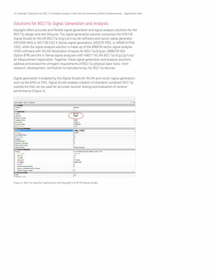
Signal generation is enabled by the Signal Studio for WLAN and vector signal generators such as the MXG or EXG. Signal Studio enables creation of standard-compliant 802.11p waveforms that can be used for accurate receiver testing and evaluation of receiver performance (Figure 4).
Figure 4. 802.11p waveform generation with Keysight’s N7617B Signal Studio.

11 | Keysight | Solutions for 802.11p Wireless Access in Vehicular Environments (WAVE) Measurements - Application Note
Signal Studio for WLAN supports the 5-, 10- and 20-MHz bandwidth modes defined in the 802.11p standard. The software’s basic options provide partially-coded signals for testing components, while its advanced options provide signals with full channel coding and flexible configuration of MAC headers. Keysight’s N7605B Signal Studio for real-time fading supports the HalfBath fading profile specifically defined for 802.11p. Using it, engineers can simulate realistic wireless channels for receiver test on the MXG or EXG X-Series vector signal generators (Figure 5). All fading parameters are configurable via the software’s interface (Figure 6).
Figure 5. Keysight’s N5182B MXG X-Series RF vector signal generator.
Figure 6. A screen shot of the 802.11p fading simulation with N7605B Signal Studio
Once the 802.11p test signals have been created, they are modulated by the vector signal generator and subsequently analyzed by the 89601B VSA software and an X-Series signal analyzer. The 89601B VSA is a comprehensive set of tools for demodulation and vector signal analysis. It supports over 45 hardware platforms, including the X-Series signal analyzers and Keysight Infiniium oscilloscopes. Option B7R provides the ability to thoroughly analyze and characterize WLAN 802.11a/b/g/p/j signals with preset settings for advanced modulation quality measurements in spectrum and time domains.

12 | Keysight | Solutions for 802.11p Wireless Access in Vehicular Environments (WAVE) Measurements - Application Note
The N9077 WLAN Measurement Application is one in a common library of more than 25 measurement applications. It transforms the X-Series signal analyzers into 802.11 standard-based WLAN transmitter testers by adding fast one-button RF conformance measurements to help engineers design, evaluate, and manufacture WLAN transmitters. The measurement application is fully compliant to the 802.11 series standards, covering 802.11a/b/g/j/p/n/ac/ah. It provides 802.11p preset tests including the SEM tests for 802.11, and also regional SEM tests as defined in the FCC and ETSI specifications (Figure 7). Keysight X-Series signal analyzers are able to measure unwanted emissions with an excellent level of accuracy and provide the dynamic range needed to measure the stricter power classes C and D of 802.11p. Moreover, the analyzers’ real-time spectrum analysis allows engineers to see, capture and understand the most elusive signals—known or unknown (Figure 8).
– Modulation accuracy: The test requirement for transmitter constellation error for 802.11p is the same as that of 802.11a. To demodulate 5-, 10- or 20-MHz 802.11p bandwidth signals, the user simply chooses the 802.11p test mode on the signal analyzer. These instruments then set the subcarrier spacing automatically in the measurement application to account for the narrower signals (Figure 9). For a 5-, 10, or 20-MHz bandwidth input signal, the subcarrier spacing is set to 78.125-, 156.25-, or 312.5-kHz, respectively.
Figure 7. SEM measurement on a 10-MHz FCC Class A, 802.11p transmitter with 0-dBm maximum output power by the Keysight N9077 WLAN Measurement Application.
Figure 8. Keysight’s N9020A MXA offers versatile real-time spectrum analysis to see, capture and understand the most elusive signals.
Figure 9. EVM measurement with Keysight N9077 WLAN Measurement Application

13 | Keysight | Solutions for 802.11p Wireless Access in Vehicular Environments (WAVE) Measurements - Application Note
Solutions for 802.11p Transmitter and Receiver Measurements For 802.11p transmitter testing (e.g., SEM, power, and modulation) and 802.11p receiver testing (e.g. sensitivity, adjacent channel rejection, and non-adjacent channel rejection), Keysight’s E6640A EXM wireless test set provides the functionality needed in a single box. The EXM one-box tester is optimized for multi-device testing with up to four transmit/receive units (TRX’s) loaded into a PXI mainframe (Figure 10). Each TRX consists of a complete vector signal analyzer, vector signal generator and calibrated RFIO that can be used to easily test multi-format devices. The EXM can be configured to test cellular products with a standard 40 MHz of analysis bandwidth and/or WLAN products with up to 160 MHz of analysis bandwidth to support the current and future wireless connectivity technologies.
Figure 10. Keysight’s EXM offers the speed, accuracy and multi-port density to ramp up rapidly and optimize full-volume manufacturing
The V9077B for EXM Wireless Test Set WLAN Measurement Application is the equivalent of the N9077 WLAN Measurement Application for the X-Series signal analyzer. It transforms the EXM into an 802.11 standard-based WLAN transmitter tester (Figure 11). With 802.11p one-button and sequence analyzer measurements and 802.11p waveform generation through Signal Studio, the EXM and V9077B solution solves 802.11p RF transmitter and receiver test challenges. In addition, the automated software can control the instrument and 802.11p chipset to enable fast and accurate automated measure-ment, helping to reduce test plan development time and effort.
Figure 11. Channel power measurement on an 802.11p transmitter using the EXM and the V9077B WLAN Measurement Application.
14 | Keysight | Solutions for 802.11p Wireless Access in Vehicular Environments (WAVE) Measurements - Application Note
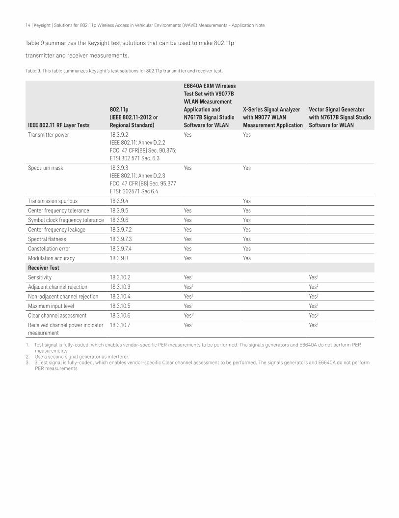
Table 9 summarizes the Keysight test solutions that can be used to make 802.11p
transmitter and receiver measurements.
Table 9. This table summarizes Keysight’s test solutions for 802.11p transmitter and receiver test.
IEEE 802.11 RF Layer Tests
802.11p(IEEE 802.11-2012 or Regional Standard)
E6640A EXM Wireless Test Set with V9077B WLAN Measurement Application and N7617B Signal Studio Software for WLAN
X-Series Signal Analyzer with N9077 WLAN Measurement Application
Vector Signal Generator with N7617B Signal Studio Software for WLAN
Transmitter power 18.3.9.2IEEE 802.11: Annex D.2.2FCC: 47 CFR[B8] Sec. 90.375;ETSI 302 571 Sec. 6.3
Yes Yes
Spectrum mask 18.3.9.3IEEE 802.11: Annex D.2.3FCC: 47 CFR [B8] Sec. 95.377ETSI: 302571 Sec 6.4
Yes Yes
Transmission spurious 18.3.9.4 Yes
Center frequency tolerance 18.3.9.5 Yes Yes
Symbol clock frequency tolerance 18.3.9.6 Yes Yes
Center frequency leakage 18.3.9.7.2 Yes Yes
Spectral flatness 18.3.9.7.3 Yes Yes
Constellation error 18.3.9.7.4 Yes Yes
Modulation accuracy 18.3.9.8 Yes Yes
Receiver Test
Sensitivity 18.3.10.2 Yes1 Yes1
Adjacent channel rejection 18.3.10.3 Yes2 Yes2
Non-adjacent channel rejection 18.3.10.4 Yes2 Yes2
Maximum input level 18.3.10.5 Yes1 Yes1
Clear channel assessment 18.3.10.6 Yes3 Yes3
Received channel power indicator measurement
18.3.10.7 Yes1 Yes1
1. Test signal is fully-coded, which enables vendor-specific PER measurements to be performed. The signals generators and E6640A do not perform PER measurements.
2. Use a second signal generator as interferer. 3. 3 Test signal is fully-coded, which enables vendor-specific Clear channel assessment to be performed. The signals generators and E6640A do not perform
PER measurements

15 | Keysight | Solutions for 802.11p Wireless Access in Vehicular Environments (WAVE) Measurements - Application Note
Designing 802.11p DevicesIn addition to standard-based 802.11p tests, Keysight provides powerful design tools for the early research and development stage of the design process. Efficiently designing the 802.11p device’s PHY layer requires appropriate modeling and simulation solutions. The solutions must offer a level of performance that’s compatible with accurate mea-surements, and be able to handle the complexity of the 802.11p standard, while being flexible enough to quickly adapt to its changing requirements.
Three solutions capable of meeting this criterion are the SystemVue, Advanced Design System (ADS) and GoldenGate software platforms from Keysight Technologies, Inc. For system-level modeling and simulation, SystemVue Electronic System Level (ESL) design software is used. SystemVue is a communications design environment that can be used to create working 802.11p waveforms, which can be uploaded to an arbitrary waveform generator (AWG) and used to modulate an RF signal generator. Using it, designers can verify and make trade-offs between the device’s baseband algorithms and system per¬formance with faded and precisely impaired channels, and various RF components.
SystemVue brings together PHY baseband algorithmic modeling, accurate RF modeling, standards-based reference intellectual property (IP), and direct interaction with test equipment. Used early in the R&D lifecycle, it follows both the RF and baseband design paths into implementation, provid¬ing continuity for cross-domain verification.
While developing 802.11p devices can be challenging, SystemVue helps simplify the process by enabling validation of early RFIC and MMIC designs in ADS and GoldenGate, prior to tape out. It also provides economical system-level validation and high-fidelity early pre-compliance using simulations, so final hardware-compliance testing can be performed more quickly and with greater confidence. Finally, it enables generation of consistent test vectors for simulation versus hardware testing.
Like SystemVue, ADS helps designers develop and share customized models prior to performing simulations to better understand performance and the impact of different devices. However, while SystemVue works at the system level, ADS targets device simulation and is extensively used in R&D. The GoldenGate RFIC simulation software platform provides yet another avenue for engineers to look at simulated performance data, before a prototype is even available. SystemVue, ADS and GoldenGate include links to Keysight’s measurement hardware compatible signal generation and signal analysis applications (e.g., Signal Studio software for signal generation, and 89600 VSA software for signal analysis).

16 | Keysight | Solutions for 802.11p Wireless Access in Vehicular Environments (WAVE) Measurements - Application Note
Summary
The automotive industry is working on the development of advanced vehicles that are safer, help improve the environment and enhance convenience. To achieve this goal, it is proactively adopting wireless technologies such as the 802.11p standard for V2V and V2I communication within the connected car. While 802.11p, in particular, offers a number of critical benefits, it also presents developers and manufacturers with many different design and test challenges. Keysight’s flexible solutions such as the X-Series signal analyzers and generators, Signal Studio software, 89600 VSA software, EEsof electronic design automation software, and the EXM offer the capabilities and performance necessary to address these challenges throughout the product lifecycle—from early R&D through manufacturing—today and in the future.
The Power to Accelerate Wireless Design and Test
Keysight is a leader in wireless test, focused on the highest-performance design and test of wireless devices and networks, with application-focused platforms optimized for existing and emerging standards. Adding to this optimal R&D and field support, Keysight allows engineers to better understand the intricacies of the continuously evolving wireless industry so you can accelerate your development of products.
To learn more about Keysight’s suite of test and measurement products please visit: www.keysight.com/find/powerofwireless
Related Applications
– N7617B Signal Studio for WLAN 802.11a/b/g/n/ac/ah – N9077 WLAN 802.11a/b/g/n/ac/ah Measurement Application – V9077B WLAN 802.11a/b/g/n/j/p/ac/ah/af Measurement Application – 89601B VSA Software with WLAN Modulation Analysis
Related Keysight Products
– SystemVue – W1917EP WLAN library for SystemVue (requires W1461BP SV ) – ADS – GoldenGate – W2385EP Wireless Networking VTB for ADS and GoldenGate (requires ADS and
either W2361EP Ptolemy or the W2381EP VTB Engine) – EXM E6640A – MXG-A N5182A – MXG-B N5182B – EXG N5172B – UXA N9040B – PXA N9030A – MXA N9020A – PXIe VXT M9420A

17 | Keysight | Solutions for 802.11p Wireless Access in Vehicular Environments (WAVE) Measurements - Application Note
This information is subject to change without notice.© Keysight Technologies, 2017Published in USA, December 1, 20175992-1353ENwww.keysight.com
www.keysight.com/find/powerofwireless
For more information on Keysight Technologies’ products, applications or services, please contact your local Keysight office. The complete list is available at:www.keysight.com/find/contactus
Americas Canada (877) 894 4414Brazil 55 11 3351 7010Mexico 001 800 254 2440United States (800) 829 4444
Asia PacificAustralia 1 800 629 485China 800 810 0189Hong Kong 800 938 693India 1 800 11 2626Japan 0120 (421) 345Korea 080 769 0800Malaysia 1 800 888 848Singapore 1 800 375 8100Taiwan 0800 047 866Other AP Countries (65) 6375 8100
Europe & Middle EastAustria 0800 001122Belgium 0800 58580Finland 0800 523252France 0805 980333Germany 0800 6270999Ireland 1800 832700Israel 1 809 343051Italy 800 599100Luxembourg +32 800 58580Netherlands 0800 0233200Russia 8800 5009286Spain 800 000154Sweden 0200 882255Switzerland 0800 805353
Opt. 1 (DE)Opt. 2 (FR)Opt. 3 (IT)
United Kingdom 0800 0260637
For other unlisted countries:www.keysight.com/find/contactus(BP-9-7-17)
DEKRA CertifiedISO9001 Quality Management System
www.keysight.com/go/qualityKeysight Technologies, Inc.DEKRA Certified ISO 9001:2015Quality Management System
Evolving Since 1939Our unique combination of hardware, software, services, and people can help you reach your next breakthrough. We are unlocking the future of technology. From Hewlett-Packard to Agilent to Keysight.
myKeysightwww.keysight.com/find/mykeysightA personalized view into the information most relevant to you.
www.keysight.com/find/emt_product_registrationRegister your products to get up-to-date product information and find warranty information.
Keysight Serviceswww.keysight.com/find/serviceKeysight Services can help from acquisition to renewal across your instrument’s lifecycle. Our comprehensive service offerings—one-stop calibration, repair, asset management, technology refresh, consulting, training and more—helps you improve product quality and lower costs.
Keysight Assurance Planswww.keysight.com/find/AssurancePlansUp to ten years of protection and no budgetary surprises to ensure your instruments are operating to specification, so you can rely on accurate measurements.
Keysight Channel Partnerswww.keysight.com/find/channelpartnersGet the best of both worlds: Keysight’s measurement expertise and product breadth, combined with channel partner convenience.