soluciones integrale4s terminales de camiones · instead of rigid piping on the secondary arm....
TRANSCRIPT
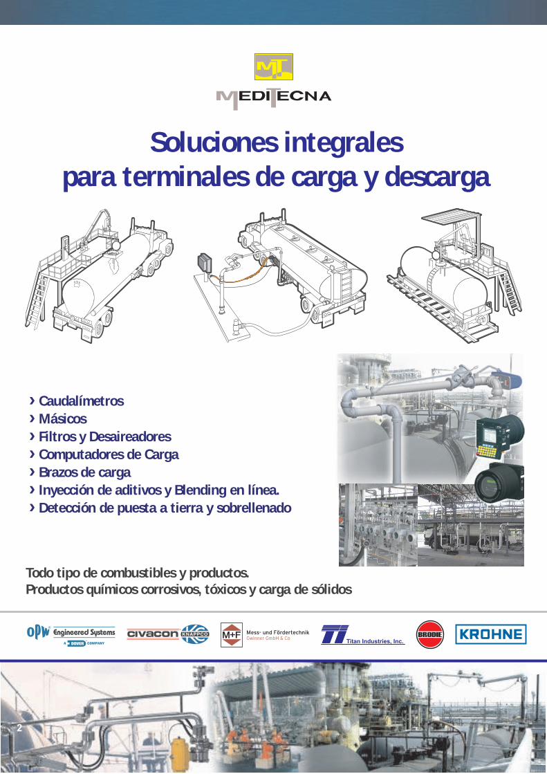
Soluciones integralespara terminales de carga y descarga
Todo tipo de combustibles y productos.Productos químicos corrosivos, tóxicos y carga de sólidos
› Caudalímetros
› Másicos
› Filtros y Desaireadores
› Computadores de Carga
› Brazos de carga
› Inyección de aditivos y Blending en línea.
› Detección de puesta a tierra y sobrellenado
Soluciones integrales para terminales de carga y descarga
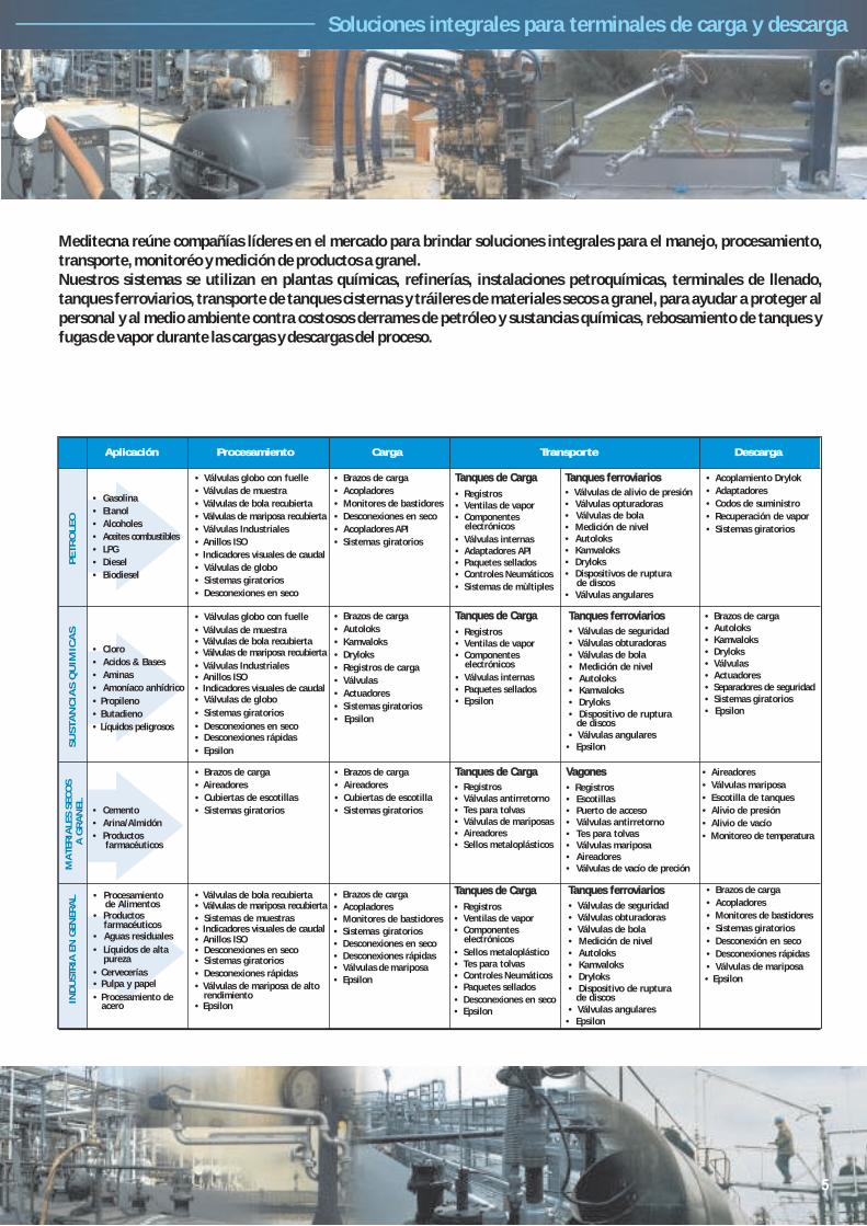
Aplicación Procesamiento Carga Transporte
• Válvulas globo con fuelle
• Válvulas globo con fuelle
• Válvulas de muestra
• Válvulas de muestra
• Válvulas de bola recubierta
• Válvulas de bola recubierta
• Válvulas de mariposa recubierta
• Válvulas de mariposa recubierta
• Válvulas Industriales
• Válvulas Industriales
• Anillos ISO
• Anillos ISO
• Indicadores visuales de caudal
• Indicadores visuales de caudal
• Válvulas de globo
• Válvulas de globo
• Sistemas giratorios
• Sistemas giratorios
• Desconexiones en seco
• Desconexiones en seco
• Brazos de carga
• Acopladores
• Monitores de bastidores
• Desconexiones en seco
• Acopladores API
• Sistemas giratorios
Tanques de Carga
• Registros• Ventilas de vapor
• Válvulas internas• Adaptadores API• Paquetes sellados• Controles Neumáticos
• Sistemas de mùltiples
Tanques ferroviarios
• Válvulas de alivio de presión• Válvulas opturadoras• Válvulas de bola• Medición de nivel• Autoloks• Kamvaloks• Dryloks• Dispositivos de ruptura
• Válvulas angulares
Descarga
• Acoplamiento Drylok
• Adaptadores
• Codos de suministro
• Recuperación de vapor
• Sistemas giratorios
• Gasolina
• Etanol
• Alcoholes
• Aceites combustibles
• LPG
• Diesel
• Biodiesel
PETR
OLEO
SU
STA
NC
IAS Q
UIM
ICA
S
• Cloro
• Acidos & Bases
• Aminas
• Amoníaco anhídrico
• Propileno
• Butadieno
• Líquidos peligrosos• Desconexiones rápidas
• Epsilon
• Brazos de carga
• Autoloks
• Kamvaloks
• Dryloks
• Registros de carga
• Válvulas
• Actuadores
• Sistemas giratorios
• Epsilon
Tanques ferroviarios
• Válvulas de seguridad• Válvulas obturadoras• Válvulas de bola• Medición de nivel• Autoloks• Kamvaloks• Dryloks• Dispositivo de ruptura
• Válvulas angulares• Epsilon
• Brazos de carga• Autoloks• Kamvaloks• Dryloks• Válvulas• Actuadores• Separadores de seguridad• Sistemas giratorios• Epsilon
MA
TERIA
LES S
ECO
S
A G
RA
NEL
• Cemento
• Arina/Almidón
• Productosfarmacéuticos
• Brazos de carga
• Aireadores
• Cubiertas de escotillas
• Sistemas giratorios
• Brazos de carga
• Aireadores
• Cubiertas de escotilla
• Sistemas giratorios
Tanques de Carga
• Registros• Válvulas antirretorno• Tes para tolvas• Válvulas de mariposas• Aireadores• Sellos metaloplásticos
Vagones
• Registros• Escotillas• Puerto de acceso• Válvulas antirretorno• Tes para tolvas• Válvulas mariposa• Aireadores• Válvulas de vacío de preción
• Aireadores
• Válvulas mariposa
• Escotilla de tanques
• Alivio de presión
• Alivio de vacío
• Monitoreo de temperatura
INDU
STR
IA E
N G
EN
ERA
L
• Brazos de carga
• Acopladores
• Monitores de bastidores
• Sistemas giratorios
• Desconexión en seco
• Desconexiones rápidas
• Válvulas de mariposa• Epsilon
• Productosfarmacéuticos
• Aguas residuales
• Cervecerías• Pulpa y papel
• Procesamiento deacero
• Procesamiento de Alimentos
• Líquidos de alta pureza
• Válvulas de bola recubierta• Válvulas de mariposa recubierta
• Epsilon
• Anillos ISO• Indicadores visuales de caudal• Sistemas de muestras
• Sistemas giratorios• Desconexiones en seco
• Desconexiones rápidas
• Válvulas de mariposa de altorendimiento
• Brazos de carga• Acopladores• Monitores de bastidores
• Desconexiones en seco• Desconexiones rápidas• Válvulas de mariposa• Epsilon
• Sistemas giratorios
• Componentes electrónicos
Tanques de Carga
• Registros• Ventilas de vapor
• Válvulas internas• Paquetes sellados• Epsilon
• Componentes electrónicos
Tanques de Carga
• Registros• Ventilas de vapor
• Sellos metaloplástico• Tes para tolvas• Controles Neumáticos• Paquetes sellados
• Desconexiones en seco• Epsilon
• Componentes electrónicos
de discos
de discos
Tanques ferroviarios
• Válvulas de seguridad• Válvulas obturadoras• Válvulas de bola• Medición de nivel• Autoloks• Kamvaloks• Dryloks• Dispositivo de ruptura
• Válvulas angulares• Epsilon
de discos
Meditecna reúne compañías líderes en el mercado para brindar soluciones integrales para el manejo, procesamiento, transporte, monitoréo y medición de productos a granel.Nuestros sistemas se utilizan en plantas químicas, refinerías, instalaciones petroquímicas, terminales de llenado, tanques ferroviarios, transporte de tanques cisternas y tráileres de materiales secos a granel, para ayudar a proteger al personal y al medio ambiente contra costosos derrames de petróleo y sustancias químicas, rebosamiento de tanques y fugas de vapor durante las cargas y descargas del proceso.

7PHONE: (800) 547-9393 • (513) 696-1500 • Fax: (800) 245-8536 • (513) 932-9845 Printed in USA 1/05
2726 Henkle Drive • Lebanon, OH 45036 • www.opw-es.com © Copyright 2005, OPW Engineered Systems
B O T T O M L O A D I N G
Unsupported Boom TypeBottom LoaderDesigned to provide flexible long-range operation, this heavy-duty configuration isboth reliable and easy to use. A minimum offive swivel planes of rotation offer completeflexibility in making tight connections forloading and unloading rail cars and tanktrucks, and servicing aviation refuelers.The outboard swivel and arm adjustsfor any changes in elevation ortilting that may result as thevehicle is loaded or unloaded.
The unsupported boom typeloader is extremely versatile andmany variations are possible. It can beequipped with dry disconnect coupler, union,quick coupling, or other customer specifiedend fitting to make connections on the side,at the rear, or underneath the vehicle. Theintermediate swivel is often inverted to achievethe low profile and clearances needed toconnect to the underside of a rail car.
Typically installed at or near ground level,arms of varying lengths can be mounted onstaggered risers to achieve crossover andneat compact storage of multiple arms ina confined space.
Benefits• Easy to operate/maneuver
• Accommodates changes in elevation
• Can be safely stored to provide for safe clearanceof vehicles
• Easy to connect under the vehicle
• Very flexible to compensate for vehicle misplacement
• Scissor-back storage means no wasted space
Features• Low profile
• Long Reach
• A minimum of five planes of rotation
• Compact storage
• Torsion Spring Balanced
• Outboard two-plane swivel joint
• Available in 2”, 3”, 4” and 6”
• Available in steel, stainless steel, aluminum, and specialty alloys
• Choice of flanged, threaded or all-welded construction
Dimensions*
Y
D T
A
U
R
OverheadView
G-32-F
Size A D T U R Yin. mm in. mm in mm in mm in mm in mm in mm
2" 51 8-1/8 206 66 1676 42 1067 8-5/8 219 17 432 8-1/8 206
3" 76 10-3/4 273 66 1676 42 1067 10-1/2 267 18 1/2 470 10-3/4 273
4" 102 12-3/4 324 66 1676 42 1067 11-3/4 298 20 508 12-3/4 324
6" 152 21-1/2 546 66 1676 42 1067 19 483 24-3/4 629 18-1/2 470
*Custom dimensions also available.

“A” Frame Loader M-32-F
The “A”-frame is one of the more popularloading arm configurations. It provides goodflexibility, long reach, and is convenient andeasy to use. It adjusts for any changes in theelevation or tilting of the vehicle during loadingor unloading. The arm stores neatly in theupright, near vertical position allowing it toswing around easily for loading from eitherside of the island.
The “A”-frame’s compact storage envelopealso allows these arms to be installed relativelyclose together, often on risers that are approximately the same height as the vehicleconnection. They can also be mounted next toone another on staggered risers to achievearm crossover for simultaneous loading ofmultiple compartment trucks.
Commonly used for tank truck bottom loading, “A”-frame arms can also be used intop loading and unloading installations. Theyare generally equipped with a dry disconnectcoupling, union, or other tight-fill fitting.
Inlet flange and seamless piping are suitablefor handling liquefied petroleum gases,including propane and butane.
Benefits• Easily stored away from vehicles
• For multiple product applications, it can bemounted close to another arm
• Can be safely stored to provide for safe clearance of vehicles
• Crossover can easily be achieved
Size A D G Z R Yin. mm in. mm in mm in mm in mm in mm in mm
2" 51 8-5/8 219 60 1524 60 1524 90 2286 17 432 8-1/8 206
3" 76 10-1/2 267 60 1524 60 1524 90 2286 18-1/2 470 10-3/4 273
4" 102 11-3/4 298 60 1524 60 1524 90 2286 20 508 12-3/4 324
*Custom dimensions also available.
Dimensions*
D
G
A
Z
Y R
OverheadView

“A” Frame Hose LoaderAFH-32-F
This spring balanced hose loader offers thesame advantages as the conventional “A”-frame arm except flexible hose is usedinstead of rigid piping on the secondary arm.
Mounting heights for this style arm areshorter than those required for other hoseloaders. This arm can be staggered toachieve crossover and conformance to theAPI envelope requirements. “A”-frame hoseloaders are normally stored in an upright,near vertical position making it possible toload from both sides of the island.
In addition to bottom loading, the “A”-frame-hose loader is often used as a vapor arm infuel terminals and can be adapted for use intop loading and unloading applications.
Minimum recommended drop hose length isapproximately 60”.
Benefits• Use as a vapor arm
• Easily stored away from vehicles
• For multiple product applications it can bemounted close to another arm
• Can be safely stored to provide for safe clearance of vehicles
• Crossover can easily be achieved
Features• Low riser mounting height
• Available in 2”, 3” and 4”
• Available in steel, stainless steel, aluminum, and specialty alloys
• Choice of flanged, threaded or all welded construction
Size A D G W R Yin. mm in. mm in mm in mm in mm in mm in mm
2" 51 8-5/8 219 60 1524 72 1829 15 381 17 432 8-1/8 206
3" 76 10-1/2 267 60 1524 72 1829 21 533 18-1/2 470 10-3/4 273
4" 102 11-3/4 298 60 1524 72 1829 21 533 20 508 12-3/4 324
*Custom dimensions also available.
Dimensions*
Y R
Overhead View
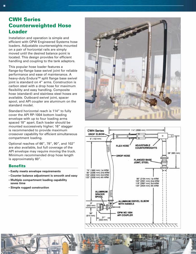
CWH SeriesCounterweighted HoseLoaderInstallation and operation is simple and efficient with OPW Engineered Systems hoseloaders. Adjustable counterweights mountedon a pair of horizontal rails are simplymoved until the desired balance point islocated. This design provides for efficienthandling and coupling to the tank adaptors.
This popular hose loader features a flange-by-flange base swivel joint for reliable performance and ease of maintenance. Aheavy-duty Endura™ split flange base swiveljoint is standard on 4” arms. Construction iscarbon steel with a drop hose for maximumflexibility and easy handling. Compositehose (standard) and stainless steel hoses areavailable. Outboard swivel joint, spacerspool, and API coupler are aluminum on thestandard model.
Standard horizontal reach is 114” to fullycover the API RP-1004 bottom loading envelope with up to four loading armsspaced 18” apart. Each loader should bemounted successively higher; 16” stagger is recommended to provide maximumcrossover capability for efficient simultaneouscompartment loading.
Optional reaches of 66”, 78”, 90”, and 102”are also available, but full coverage of theAPI envelope may require moving the truck.Minimum recommended drop hose length is approximately 60”.
Benefits• Easily meets envelope requirements
• Counter balance adjustment is smooth and easy
• Multiple compartment loading capability saves time
• Simple rugged construction
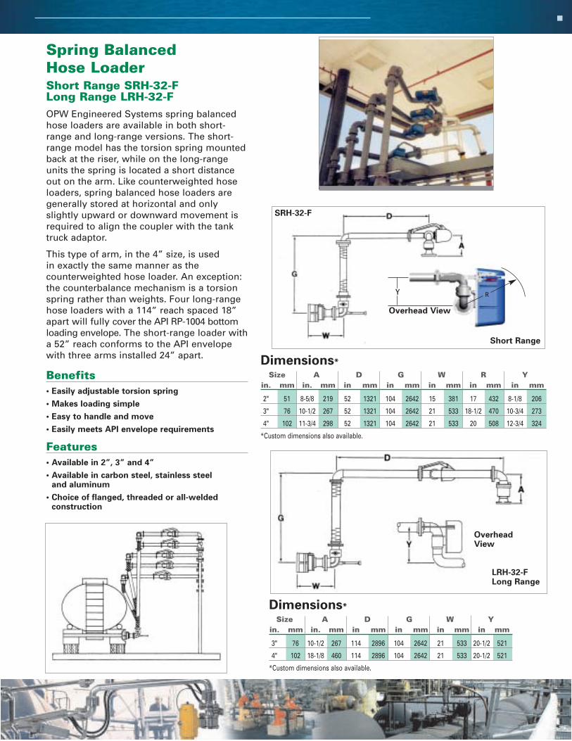
Spring Balanced Hose Loader Short Range SRH-32-FLong Range LRH-32-FOPW Engineered Systems spring balancedhose loaders are available in both short-range and long-range versions. The short-range model has the torsion spring mountedback at the riser, while on the long-rangeunits the spring is located a short distanceout on the arm. Like counterweighted hoseloaders, spring balanced hose loaders aregenerally stored at horizontal and onlyslightly upward or downward movement isrequired to align the coupler with the tanktruck adaptor.
This type of arm, in the 4” size, is used in exactly the same manner as the counterweighted hose loader. An exception:the counterbalance mechanism is a torsionspring rather than weights. Four long-rangehose loaders with a 114” reach spaced 18”apart will fully cover the API RP-1004 bottomloading envelope. The short-range loader witha 52” reach conforms to the API envelopewith three arms installed 24” apart.
Benefits• Easily adjustable torsion spring
• Makes loading simple
• Easy to handle and move
• Easily meets API envelope requirements
Features• Available in 2”, 3” and 4”
• Available in carbon steel, stainless steel and aluminum
• Choice of flanged, threaded or all-welded construction
Size A D G W R Yin. mm in. mm in mm in mm in mm in mm in mm
2" 51 8-5/8 219 52 1321 104 2642 15 381 17 432 8-1/8 206
3" 76 10-1/2 267 52 1321 104 2642 21 533 18-1/2 470 10-3/4 273
4" 102 11-3/4 298 52 1321 104 2642 21 533 20 508 12-3/4 324
*Custom dimensions also available.
Dimensions*
Size A D G W Yin. mm in. mm in mm in mm in mm in mm
3" 76 10-1/2 267 114 2896 104 2642 21 533 20-1/2 521
4" 102 18-1/8 460 114 2896 104 2642 21 533 20-1/2 521
*Custom dimensions also available.
Dimensions*
Short Range
SRH-32-F
LRH-32-FLong Range
OverheadView
Y R
Overhead View

1004D2/1005E API CouplerThe OPW Engineered Systems 1004D2 isthe standard in “drip-less” bottom loadingcouplers and a proven performer at majoroil terminals worldwide. The 1004D2 mateswith all 4” bottom loading adaptors built inaccordance with API RP-1004 requirements tosignificantly reduce liquid loss at disconnectin gasoline applications.
Benefits• Designed to effectively handle all fuels – high
performance Viton® seals are standard, providingexcellent wear and fuel resistance. Compatiblewith gasoline with up to 20% MTBE content.Suitable for use at service temperatures as lowas -10ºF. Other seals include Buna-N, Chemraz®,and Kalrez®.
• Designed for “less mess” at your loading rack –the new, easy, self-aligning 5-Cam design ensuresa tight connection to truck adaptor and resistsside forces. The 1004D2 cannot be opened unlessit is properly connected to an API adaptor norcan it be disconnected when the poppet is open.
• Eliminates risk of nose seal “blow out” –beveled for superior sealing, the new highretention nose seal is specifically designed toeliminate the risk of seal “blow out” due to lineover-pressurization and thermal expansion.
• Long-life performance – extended wearoperating lever has a built-in roller bearing toprovide smoother operation and extended life.
• Smoother, easier operation – the built-in rollerbearing handle and Teflon® impregnated poppetand cylinder provide for smoother, easiermovement.
• Easy to grasp, even with gloves – large handlesprovide for easy handling.
• Easy and inexpensive to maintain – seal andconversion kits available
• Lightweight – only 8.5 lbs.
• Easy-to-change nose seal – simply pull out overthe poppet without disassembly.
• Dependable parts – all wetted parts are stainlesssteel or hard-coated anodized aluminum; internallinkage parts are hardened stainless steel.
Features• Heavy-duty body
• Heavy-duty internal components – stainless steel and Teflon®
impregnated hard-coat anodized aluminum internal parts
• High retention nose seal – beveled for superior sealing
• Heavy-duty sleeve
• Rugged operating handle – with built-in roller bearing forsmooth operation
• Large, convenient grasp handles
• Available seals include – Teflon®, Viton®, Buna-N, Kalrez® andChemraz®
• Coupler available in 4” size only
• Secure cylinder – series of three retainers prevent the cylinderfrom inadvertently coming out of the coupler body
• Shaft Seal – simple and reliable, consisting of a single heavycross-section O-ring
• 300 psi (20 bar) pressure rating – reinforced internal partsminimize effects of thermal expansion
• Seal Kits – include everything needed to change out all seals in the1004D2 Bottom Loading Coupler. Available in high-performanceViton® (1004D2SRK) and Buna-N (1004D2SRK-0401)
• Conversion Kits – available to convert a 1004 to a 1004D2. Includespoppet, cylinder and beveled nose seal, shaft seal, cylinder sealand other items included in all OPW coupler repair kits. Highperformance Viton® (1004D2CK-0402) or Buna-N (1004D2CK-0401)
Ordering Specifications
NUMBER DESCRIPTION SIZE CONSTRUCTION SEALS WT.
1004D2-0401 High Pressure Drip-Less 4" Aluminum Buna-N 18.5 lbs.
API Bottom Coupler
1004D2-0402 High Pressure Drip-Less 4" Aluminum Viton® 18.5 lbs.
API Bottom Coupler
1005E-0401 5-Cam API Coupler with 4" Aluminum Buna-N 19.0 lbs.
Grasp Knobs – 350 PSI
1005E-0402 5-Cam API Coupler with 4" Aluminum Viton® 19.0 lbs.
Grasp Knobs – 350 PSI
1004-D2 1005E

CWH SeriesCounterweighted HoseLoaderInstallation and operation is simple and efficient with OPW Engineered Systems hoseloaders. Adjustable counterweights mountedon a pair of horizontal rails are simplymoved until the desired balance point islocated. This design provides for efficienthandling and coupling to the tank adaptors.
This popular hose loader features a flange-by-flange base swivel joint for reliable performance and ease of maintenance. Aheavy-duty Endura™ split flange base swiveljoint is standard on 4” arms. Construction iscarbon steel with a drop hose for maximumflexibility and easy handling. Compositehose (standard) and stainless steel hoses areavailable. Outboard swivel joint, spacerspool, and API coupler are aluminum on thestandard model.
Standard horizontal reach is 114” to fullycover the API RP-1004 bottom loading envelope with up to four loading armsspaced 18” apart. Each loader should bemounted successively higher; 16” stagger is recommended to provide maximumcrossover capability for efficient simultaneouscompartment loading.
Optional reaches of 66”, 78”, 90”, and 102”are also available, but full coverage of theAPI envelope may require moving the truck.Minimum recommended drop hose length is approximately 60”.
Benefits• Easily meets envelope requirements
• Counter balance adjustment is smooth and easy
• Multiple compartment loading capability saves time
• Simple rugged construction
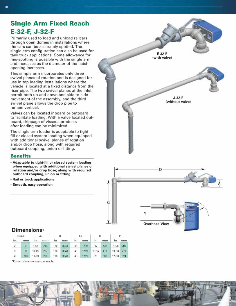
Single Arm Fixed ReachE-32-F, J-32-FPrimarily used to load and unload railcarsthrough open domes in installations wherethe cars can be accurately spotted. The single arm configuration can also be used fortank truck applications. Some allowance formis-spotting is possible with the single armand increases as the diameter of the hatchopening increases.This simple arm incorporates only threeswivel planes of rotation and is designed foruse in top loading installations where thevehicle is located at a fixed distance from theriser pipe. The two swivel planes at the inletpermit both up-and-down and side-to-sidemovement of the assembly, and the thirdswivel plane allows the drop pipe to remain vertical. Valves can be located inboard or outboard to facilitate loading. With a valve located out-board, drippage of viscous products after loading can be minimized.The single arm loader is adaptable to tightfill or closed system loading when equippedwith additional swivel planes of rotationand/or drop hose, along with required outboard coupling, union or fitting.
Benefits• Adaptable to tight-fill or closed system loading
when equipped with additional swivel planes ofrotation and/or drop hose; along with requiredoutboard coupling, union or fitting
• Rail or truck applications
• Smooth, easy operation
Size A D G R Yin. mm in. mm in mm in mm in mm in mm
2" 51 8-5/8 219 120 3048 48 1219 17 432 8-1/8 206
3" 76 10-1/2 267 120 3048 48 1219 18-1/2 470 10-3/4 273
4" 102 11-3/4 298 120 3048 48 1219 20 508 12-3/4 324
*Custom dimensions also available.
Dimensions*
A
D
Y R
Overhead View
J-32-F(without valve)
E-32-F(with valve)
G
“A” Frame Loader M-32-F
The “A”-frame is one of the more popularloading arm configurations. It provides goodflexibility, long reach, and is convenient andeasy to use. It adjusts for any changes in theelevation or tilting of the vehicle during loadingor unloading. The arm stores neatly in theupright, near vertical position allowing it toswing around easily for loading from eitherside of the island.
The “A”-frame’s compact storage envelopealso allows these arms to be installed relativelyclose together, often on risers that are approximately the same height as the vehicleconnection. They can also be mounted next toone another on staggered risers to achievearm crossover for simultaneous loading ofmultiple compartment trucks.
Commonly used for tank truck bottom loading, “A”-frame arms can also be used intop loading and unloading installations. Theyare generally equipped with a dry disconnectcoupling, union, or other tight-fill fitting.
Inlet flange and seamless piping are suitablefor handling liquefied petroleum gases,including propane and butane.
Benefits• Easily stored away from vehicles
• For multiple product applications, it can bemounted close to another arm
• Can be safely stored to provide for safe clearance of vehicles
• Crossover can easily be achieved
Size A D G Z R Yin. mm in. mm in mm in mm in mm in mm in mm
2" 51 8-5/8 219 60 1524 60 1524 90 2286 17 432 8-1/8 206
3" 76 10-1/2 267 60 1524 60 1524 90 2286 18-1/2 470 10-3/4 273
4" 102 11-3/4 298 60 1524 60 1524 90 2286 20 508 12-3/4 324
*Custom dimensions also available.
Dimensions*
D
G
A
Z
Y R
OverheadView
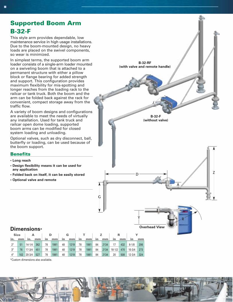
Supported Boom ArmB-32-FThis style arm provides dependable, lowmaintenance service in high usage installations.Due to the boom-mounted design, no heavyloads are placed on the swivel components,so wear is minimized.In simplest terms, the supported boom armloader consists of a single-arm loader mountedon a swiveling boom that is attached to apermanent structure with either a pillowblock or flange bearing for added strengthand support. This configuration providesmaximum flexibility for mis-spotting andlonger reaches from the loading rack to therailcar or tank truck. Both the boom and thearm can be folded back against the rack forconvenient, compact storage away from thetraffic flow.A variety of boom designs and configurationsare available to meet the needs of virtuallyany installation. Used for tank truck and railcar open dome loading, supported boom arms can be modified for closedsystem loading and unloading.Optional valves, such as dry disconnect, ball,butterfly or loading, can be used because ofthe boom support.
Benefits• Long reach
• Design flexibility means it can be used for any application
• Folded back on itself, it can be easily stored
• Optional valve and remote
Size A D G T Z R Yin. mm in. mm in mm in mm in mm in mm in mm in mm
2" 51 14-1/4 362 78 1981 48 1219 78 1981 84 2134 17 432 8-1/8 206
3" 76 17-3/4 451 78 1981 48 1219 78 1981 84 2134 18-1/2 470 10-3/4 273
4" 102 20-3/4 527 78 1981 48 1219 78 1981 84 2134 20 508 12-3/4 324
*Custom dimensions also available.
Dimensions*
D
G
Z
A
B-32-F(without valve)
B-32-RF(with valve and remote handle)
Y R
Overhead View

Unsupported Boom ArmGT-32-FThe unsupported boom arm is an excellentalternative for variable reach applications,especially in larger sizes where the outboardcomponents are relatively heavy. It can bemodified for closed system loading andunloading, and is available in various designconfigurations to meet the needs of virtuallyany installation.
This popular style loader is designed forthose installations where it is undesirable orimpractical to mount a supported boom arm.For example, many railcar sites have no support columns or overhead structures towhich a supported boom can be attached.
The unsupported boom arm offers the same advantages as the supported boomarm, but maximum reach is somewhat less. It provides good flexibility formis-spotting, and can be folded back againstthe rack for convenient, compact storage.When necessary, increasing the size of the base joint, or using a heavy-duty splitflange swivel at the inlet, can extend total reach.
Benefits• Optional valving allows liquid to be held
in the line
• Long reach compensates for mis-spotting
• Compact storage
Features• Available in 2", 3" and 4”
• Available in carbon steel, stainless steel, aluminum and specialty alloys
• Choice of flanged, threaded or all-welded construction
Size A D G T U R Yin. mm in. mm in mm in mm in mm in mm in mm in mm
2" 51 8-1/8 206 78 1981 48 1219 48 1219 8-5/8 219 17 432 8-1/8 206
3" 76 10-3/4 273 78 1981 48 1219 48 1219 10-1/2 267 18-1/2 470 10-3/4 273
4" 102 12-3/4 324 78 1981 48 1219 48 1219 11-3/4 298 20 508 12-3/4 324
*Custom dimensions also available.
Dimensions*
G-T-32-F
GT-32-F(reverse view)
Y R
Overhead View
D
TG
A
U

“A” Frame Hose LoaderAFH-32-F
This spring balanced hose loader offers thesame advantages as the conventional “A”-frame arm except flexible hose is usedinstead of rigid piping on the secondary arm.
Mounting heights for this style arm areshorter than those required for other hoseloaders. This arm can be staggered toachieve crossover and conformance to theAPI envelope requirements. “A”-frame hoseloaders are normally stored in an upright,near vertical position making it possible toload from both sides of the island.
In addition to bottom loading, the “A”-frame-hose loader is often used as a vapor arm infuel terminals and can be adapted for use intop loading and unloading applications.
Minimum recommended drop hose length isapproximately 60”.
Benefits• Use as a vapor arm
• Easily stored away from vehicles
• For multiple product applications it can bemounted close to another arm
• Can be safely stored to provide for safe clearance of vehicles
• Crossover can easily be achieved
Features• Low riser mounting height
• Available in 2”, 3” and 4”
• Available in steel, stainless steel, aluminum, and specialty alloys
• Choice of flanged, threaded or all welded construction
Size A D G W R Yin. mm in. mm in mm in mm in mm in mm in mm
2" 51 8-5/8 219 60 1524 72 1829 15 381 17 432 8-1/8 206
3" 76 10-1/2 267 60 1524 72 1829 21 533 18-1/2 470 10-3/4 273
4" 102 11-3/4 298 60 1524 72 1829 21 533 20 508 12-3/4 324
*Custom dimensions also available.
Dimensions*
Y R
Overhead View

Vapor recovery systems consist of two flow passage lines, one to convey the product and theother to recover and transfer the product vapors.Separate product and vapor arms can be installed atthe loading rack but systems that incorporate theproduct and vapor lines into a single system arepreferred because both connections can then beconveniently moved out to the transporter simultaneously. Two basic designs with many variations are available:
The OPW Engineered Systems “piggyback” style
arm is simple in design yet very functional. It hasthe vapor line welded to the product arm. Thisversatile arm can also serve as an unloader byusing the “vapor” line to pressurize a railcar ortank truck equipped with a permanent deep pipe.
The Dual Arm or Siamese configuration is themost widely used style vapor recovery assembly.It features separate arms for product and vaporthat are joined together at the inner boom structure. One of the more popular variations ofthis design also has the two counterbalanceswivels and the outer arms joined together in aside-by-side arrangement to minimize the overallvertical dimension of the outboard assembly. Onmost dual arm designs the product line feedsfrom beneath and the vapor line from overhead.
When loading tank trucks and railcars that areequipped with permanent product and vapor connections, the end fittings on the loading armare typically quick disconnect couplings, drydisconnect couplings, unions, or flanges.
A variety of vapor recovery components are available for those applications where loadingtakes place through an open dome. These includecover plates, tapered hatch plugs/cones, and theOPW inflatable hatch seal.
Vapor recovery loading and unloading systemscan be steam jacketed or traced, equipped with automatic shut-off controls, or outfitted with whatever additional equipment might be neededfor your particular application.
OPW Engineered Systems vapor recovery assembliesare available in 2”, 3”, 4”, and 6”. They are alsoavailable in steel, stainless steel, aluminum,and specialty alloys.
Please consult the factory with your specifications and we will design a vapor recovery loading system to meet your needs.
T O P L O A D I N G V A P O R R E C O V E R Y
Pneumatically Actuated Arm
“Piggyback” Arm
Dual Arm Configuration

Vapor Recovery ComponentsInflatable Hatch SealOPW Engineered Systems developed the 7300IHS InflatableHatch Seal specifically for applications where loading isdone through an open hatch where a vapor-tight seal isneeded in the opening. The OPW 7300IHS provides a reliable means of sealing off different size and depth hatchopenings on tank trucks and railcars to prevent the releaseof vapors into the atmosphere. As the seal is inflated, itexpands outward, centering itself and forming a tight sealagainst the inner wall of the hatch.
Benefits• Effective in hatches from 15” to 24” in diameter with
tank pressures up to 2 psig.
• Requires no downward force to achieve a seal, so it canbe used accurately on scale-equipped racks
• Fits around the inside perimeter of the hatch for a tighterseal than tapered hatch plugs can provide
• Available in EPDM, PTFE coated nitrile and fluorosiliconefor a wide range of chemical compatibility
• Can be used on loading arms or for conventionalhose loading
• Requires only a supply of dry compressed air or nitrogenfor operation
Features• Stainless steel construction
• Available in various elastomeric seals
• Comes complete with a pneumatics/nitrogen packagethat is preset at the factory for a maximum inflationpressure of 5 psig.
• Core assemblies are customized with the pipe sizes,lengths, and connections required for eachspecific application
• Optional lockdown mechanism available
Tapered PlugTapered plugs are an economical means of closing offhatches of different sizes in order to recover vapors or keepdebris out. There is no need to have a compressed air orgas line run to the loading point. Additional sensors andconnections can be added to the tapered plug seal.
Features• Made of steel, stainless steel, or aluminum
• Adaptable to many fitting configuration
• Can be fitted with dry break couplings
Hatch Cover Vapor PlatesHatch cover vapor plates are used to retain and recoverharmful vapors and avoid excessive splashing (especially on tank wash arms). They also are used to prevent dirt, moisture, insects, and foreign objects from entering the tank.
Flat Hatch Seal Inflated Hatch Seal
Hatch Cover Vapor Plates Tapered Hatch Seal
Inflated Hatch Seal
Most vapor plates are manufactured with lockingmechanisms or hold-down clamps, and canaccommodate liquid sensing devices or overfillprotection instrumentation.
Features• Can be configured many ways, including dry break couplings
• Made of steel, stainless steel or aluminum
• Can be added to the arm when needed
• Long-lasting, durable construction

This AFH-32-F spring balanced hose loaderis ideal for vapor recovery. Stage I vapor
recovery requires truck transports to off-load vapors while loading fuels.
OPW Engineered Systems is a leader in environmentally safe products.
Here a G-32-F is attached to a riser located atground level. It offers an easy way to bottomunload a rail car. While not in use you can seehow it is easily “parked” outside the railroadenvelope. Further down the tracks you can see ahose attached to a riser, inside the envelope andperilously close to the rail.
The illustration to the right shows a by-pass loading arm. In this application, the loading arm
is not carrying product but is carrying the loadof the pipes above it. This application is typical
of a situation where the customer wanted to usecomponents that were compatible with the
liquid and needed the arm to act as a support,holding the load while making it easy to
manipulate and control loading.
The photo to the left shows how loading arms can be made to crossover each other to facilitateloading of various compartments in a tanker truck.Note the canopy. It’s height limited the verticaltravel of the loading arms. Design considerationslike this are very important. Your OPW sales representative will be glad to make an on-site evaluation of your loading area.
A P P L I C A T I O N S
C U S T O M A P P L I C A T I O N S
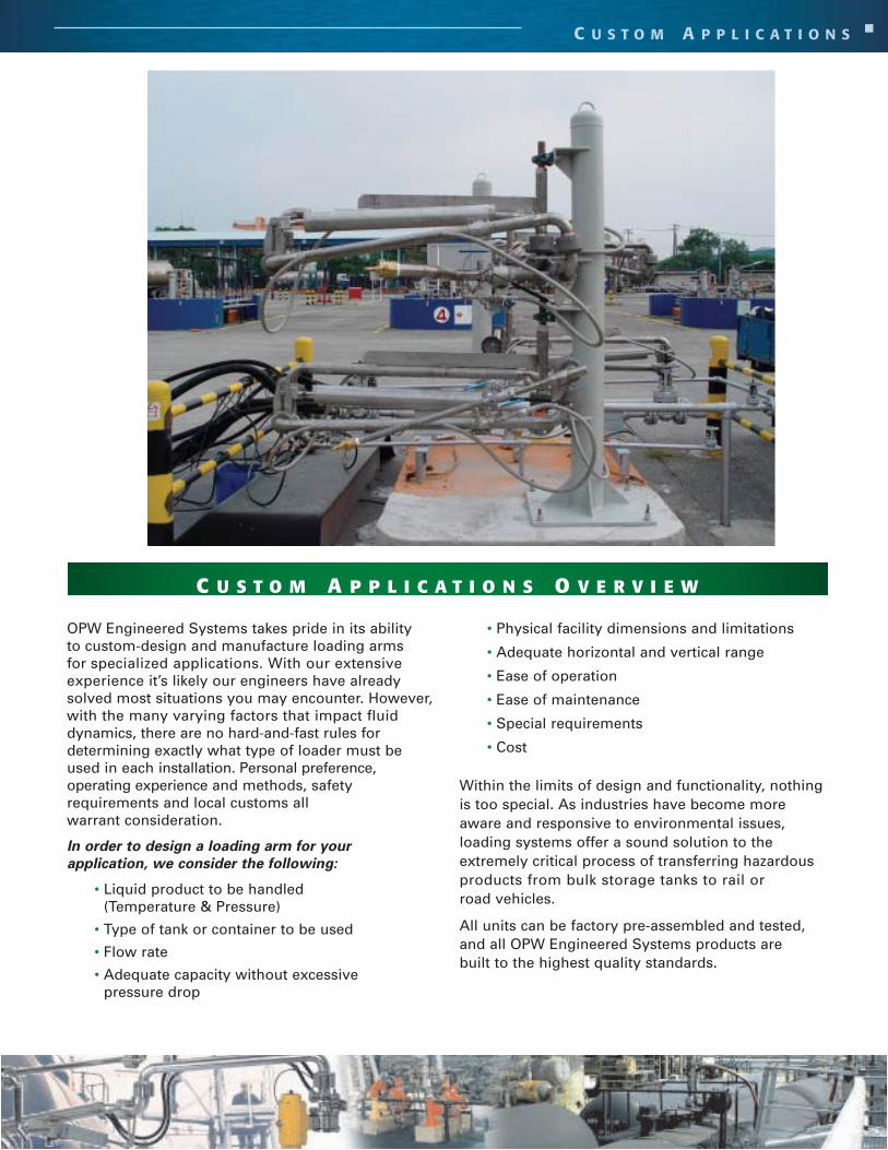
OPW Engineered Systems takes pride in its ability to custom-design and manufacture loading armsfor specialized applications. With our extensiveexperience it’s likely our engineers have alreadysolved most situations you may encounter. However,with the many varying factors that impact fluiddynamics, there are no hard-and-fast rules for determining exactly what type of loader must beused in each installation. Personal preference, operating experience and methods, safety requirements and local customs all warrant consideration.
In order to design a loading arm for your
application, we consider the following:
• Liquid product to be handled (Temperature & Pressure)
• Type of tank or container to be used
• Flow rate
• Adequate capacity without excessive pressure drop
• Physical facility dimensions and limitations
• Adequate horizontal and vertical range
• Ease of operation
• Ease of maintenance
• Special requirements
• Cost
Within the limits of design and functionality, nothingis too special. As industries have become moreaware and responsive to environmental issues,loading systems offer a sound solution to theextremely critical process of transferring hazardousproducts from bulk storage tanks to rail orroad vehicles.
All units can be factory pre-assembled and tested,and all OPW Engineered Systems products are built to the highest quality standards.
C U S T O M A P P L I C A T I O N S O V E R V I E W
Steam Jacketed Loading ArmsOPW Engineered Systems top and bottomloaders can be fully or partially jacketed/traced for efficient handling of asphalt,molten sulfur, waxes, resins, and other products that are highly viscous or tend tosolidify at ambient temperatures.
OPW steam jacketed loading arms incorporatea “pipe in a pipe” design and are used tohandle products that need to be transferred atelevated temperatures. The inner pipe conveysthe product being handled, while the outerpipe or jacket contains the steam. With thesearms, the product can be heated very quicklyand uniformly.
In some cases, customers specify the use of heat transfer fluids. The same principlesapply in terms of loading arm design.
We also manufacture, for less demandingapplications, hollow core steam trace elementsthat are clamped and bonded to the straightsections of piping in the loading arm.
24
C U S T O M A P P L I C A T I O N S
The systems shown are some of the more popular configurations. Many others are available and can
be tailored to meet your specific requirements.
All OPW Engineered Systems steam jacketed loading arms arecustom designed to specifications depending upon the productbeing handled, temperature, and overall reach and flexibilityrequirements. Please consult the factory with your specificationsand application requirements.
Benefits• Rugged construction
• Custom made to your specifications
• Durable for many years of service life
Features• Assemblies are supplied with all
necessary steam jumper hoses
• Threaded, flanged, and weldedconstruction are available
• Available in 2", 3", 4" and 6"sizes
• Available in steel, stainlesssteel, and aluminum
Automatic Shut-OffSystemsVirtually any OPW Engineered Systems toploader can be equipped with an automaticshut-off feature to help prevent spillage andoverfills that can result when working witha remote valve.
The automatic shut-off feature allows anoperator to load using multiple arms tomake the loading operation more efficientand safer.
Both electrical and pneumatically operatedshut-off systems are available. An adjustablelevel sensor mounted on the drop tube orvapor recovery plate works in conjunctionwith an actuated valve to stop flow when thepredetermined fill level is reached. Electricalsystems with multiple sensing points can beused to trigger a number of actions such asclosing a valve, slowing down a pump, orsounding an alarm.
Benefits• Provides for a faster, safer
loading operation
• Allows for loading with morethan one arm at a time withoutcompromising safety
• Prevents overfills
• Safe controlled filling
• Signals the operator or shutsdown the system
• Prevents spillage
Features• Electrical or pneumatic
instruments available
• Adjustable lever sensor detectschanges in liquid levels to stopflow at predetermined levels
• Can be configured to activatevalves or alarms
25PHONE: (800) 547-9393 • (513) 696-1500 • Fax: (800) 245-8536 • (513) 932-9845 Printed in USA 1/05
2726 Henkle Drive • Lebanon, OH 45036 • www.opw-es.com © Copyright 2005, OPW Engineered Systems
C U S T O M A P P L I C A T I O N S
By-Pass Loading ArmsOPW By-Pass Loading Arms are designed asa low-cost alternative to arms constructed ofHastelloy®, Alloy 20®, and other specialtymetals used to transfer hydrochloric acid and other corrosive chemicals.
This unique design offers:
• All the ease of operation and handling advantages of conventional spring balance loaders
• Liquid by-pass of steel swivel – no liquid passesthrough the base swivel
• Base swivel, in conjunction with torsion springserves as a support and carrying mechanism only
• Flow passage – consists of lined pipe, plasticpipe, and a hose suspended from the support arm
• Available in 2", 3", and 4" sizes in a variety ofconfigurations
Wash ArmsOPW Wash Arms eliminate the chore ofmanually carrying cumbersome, heavy hose and spray attachments to the rail car or tanker.
• Completely supports all other washing systemcomponents
• Folds into a conveniently stored position, out ofthe way of normal operations
C-33-RF Scissor Armwith Downfeed Loading• Deadman loading valve with remote control
operating lever and outlet deflector
Remote Control Unit (1000-RC)The OPW 1000-RC remote control unitprovides convenient control of the loadingvalve from the outboard end of the loadingarm. The 1000-RC consists of an arm clamp,lever handle and connection rod. Availablefor all OPW Type A, B, C, and E liquid loaders.
C-33-RF
1000-RCRemote Control
Product Flow
26IMPORTANT: OPW products should be used in compliance with applicable federal, state, provincial, and local laws and regulations. Product selection should bebased on physical specifications and limitations and compatibility with the environment and materials to be handled. OPW MAKES NO WARRANTY OF FITNESSFOR A PARTICULAR USE. All illustrations and specifications in this literature are based on the latest product information available at the time of publication.OPW reserves the right to make changes at any time in prices, materials, specifications and models and to discontinue models without notice or obligation.
C U S T O M A P P L I C A T I O N S
D-32-FF Scissor ArmWith Valve Outboard ForViscous Products
Boom-Type LoaderWith Self-DrainingConfiguration(Note: The primary arm section is angled down for drainage)
Drum Filling Arms• Make it easy to load both open drums and
those with small bung openings
• Designed to provide the range of flexibilityneeded for loading drums at any orientationon pallet
• Easy operation ensures faster loading
D-32-FF
2˚ Slope
PHONE: (800) 547-9393 • (513) 696-1500 • Fax: (800) 245-8536 • (513) 932-9845 Printed in USA 1/05
2726 Henkle Drive • Lebanon, OH 45036 • www.opw-es.com © Copyright 2005, OPW Engineered Systems
C U S T O M A P P L I C A T I O N S
Mongoose™ Fluid Transfer SystemThe OPW Engineered Systems Mongoose™ Fluid Transfer Systemis specifically designed to help companies improve worker safetyand performance by replacing hose-based “snake pit” operationswith an organized system of self-balanced, articulating fluid transfer arms. The Mongoose™ system is neat and organized,which improves productivity and dramatically reduces the tripping, heavy lifting and moving hazards of the traditional“snake pit” caused by the use of hoses.
The Mongoose™ system is particularly beneficial in blending operations and drum filling operations where finished productmanifold and raw material manifold systems use multiple transferlines and hoses.
Because every snake pit operation is unique, everyMongoose™ system is designedto meet customer-specific appli-cation requirements. Thisrequires design collaborationbetween your company andOPW’s design and engineeringteam to ensure creation of themost effective system possible.OPW applies a regimented design process that begins with acomplete site analysis. This site analysis identifies the project’sobjectives and provides and in-depth evaluation of connectivityrequirements and percentages, structural restrictions, andexisting conditions. Once the site analysis is complete, a system recommendation is provided along with potential project costs.
A Mongoose™ system can be developed to improve virtuallyany type of existing snake pit or transfer system that uses multiple destinations and connections, including rotary, horizontal and vertical drop configurations. With theMongoose™, the snake pit is cleaned-up and out of the way. No more lifting or time-consuming sorting of hoses to find the right hose for the fitting connection. And, all OPW loadingarms can be designed to be piggable, so line clean-up is quick and efficient.
Benefits• Improves safety and productivity by eliminating the cumbersome
loose hoses typical of “snake pit” operations
• Provides for a neat, clean and organized working environment
• Can be used for drum filling or blending operations where multiplesource-to-destination connections and manifolds are used
• Individually designed to meet specific application requirementsusing advanced technology and collaborative teamwork
Features• Available in carbon steel, aluminum, and stainless steel
• Torsion spring design provides for smooth and easy operationand positioning
• High quality design, engineering and construction – built to thesame rigid global standards of all OPW Engineered Systems loading arms and products
27
Before Traditional “Snake Pit” Operation
After the Mongoose™ Has Killedthe “Snake Pit” Operation
Mongoose™ Fluid Transfer System

IMPORTANT: OPW products should be used in compliance with applicable federal, state, provincial, and local laws and regulations. Product selection should bebased on physical specifications and limitations and compatibility with the environment and materials to be handled. OPW MAKES NO WARRANTY OF FITNESSFOR A PARTICULAR USE. All illustrations and specifications in this literature are based on the latest product information available at the time of publication.OPW reserves the right to make changes at any time in prices, materials, specifications and models and to discontinue models without notice or obligation.
C U S T O M A P P L I C A T I O N S
PneumaticallyControlledLoadersThe OPW Engineered Systems pneumatically controlled loaders aredesigned specifically to help make operations more simple, safe and efficient. Pneumatic actuated loadingsystems utilize air to create leveragepoints that allow the loading arm to bemoved and positioned effortlessly. And, because they are designed for precision control, theloader can be easily handled by one operator without heavy pushing, pullingand lifting. Strenuous lifting or moving by the operator is eliminated.
Benefits
• Easy to Operate/Maneuver – air
controlled actuation eliminates
strenuous pushing, pulling or lifting
• Long range design to compensate for
vehicle misplacement
• Easily stores away from vehicles
• Safely stores outside the envelope of clearance
• Available in both bottom and top loader
configurations
Features
• Available in 2", 3", 4” and 6"
• Available in steel, stainless steel, aluminum and
specialty alloys
• Choice of flanged, threaded or all-welded
construction
28

29PHONE: (800) 547-9393 • (513) 696-1500 • Fax: (800) 245-8536 • (513) 932-9845 Printed in USA 1/05
2726 Henkle Drive • Lebanon, OH 45036 • www.opw-es.com © Copyright 2005, OPW Engineered Systems
F L O A T I N G S U C T I O N A S S E M B L I E S
Internal Tank FloatingSuction Assemblies764, 765, 766 SeriesOPW Engineered Systems manufacturesfloating suction assemblies for use in horizontal or vertical, above or below groundstorage tanks where little or no contaminationcan be tolerated, such as aircraft jet fuel.Since the fuel near the top is least likely tocontain water or foreign particles, theseassemblies are designed to float near the top of the liquid surface and draw from thisnear-surface, contamination-free liquid. Ourfloating suctions are engineered for long,trouble-free life.
Benefits• Maintenance free
• Easy movement in the liquid
• Increases efficiency and decreases maintenanceof filter separators
Features• Permanently lubricated dual race swivel joints
• Triple sealed swivel joints for submerged service
• Suction baffle and stop lag maintains minimumintake level of 8” above tank bottom (or as specified)
• Aluminum 150 lb. flat-faced flanges are standard; steel and stainless steel are available
Size A D R W S (optional)
in. mm in. mm in mm in mm in mm in mm
2" 51 5-1/2 140 121-1/4 3080 28-1/2 714 6-1/2 165 108 2743
3" 76 5 127 121-1/4 3080 28-1/2 714 6-1/4 159 108 2743
4" 102 6-1/16 154 121-1/4 3080 28-1/2 714 6-1/2 165 108 2743
6" 152 7-3/4 197 120-1/8 3051 28-1/2 714 6-3/4 171 108 2743
*Custom dimensions also available.
Dimensions*
DW
R
S
A
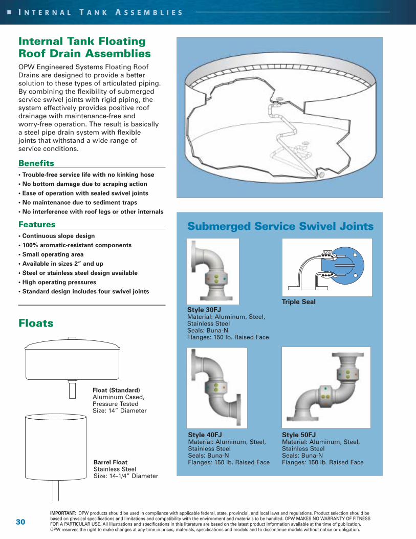
Internal Tank FloatingRoof Drain AssembliesOPW Engineered Systems Floating RoofDrains are designed to provide a better solution to these types of articulated piping.By combining the flexibility of submergedservice swivel joints with rigid piping, thesystem effectively provides positive roofdrainage with maintenance-free and worry-free operation. The result is basically a steel pipe drain system with flexible joints that withstand a wide range of service conditions.
Benefits• Trouble-free service life with no kinking hose
• No bottom damage due to scraping action
• Ease of operation with sealed swivel joints
• No maintenance due to sediment traps
• No interference with roof legs or other internals
Features • Continuous slope design
• 100% aromatic-resistant components
• Small operating area
• Available in sizes 2” and up
• Steel or stainless steel design available
• High operating pressures
• Standard design includes four swivel joints
Floats
30IMPORTANT: OPW products should be used in compliance with applicable federal, state, provincial, and local laws and regulations. Product selection should bebased on physical specifications and limitations and compatibility with the environment and materials to be handled. OPW MAKES NO WARRANTY OF FITNESSFOR A PARTICULAR USE. All illustrations and specifications in this literature are based on the latest product information available at the time of publication.OPW reserves the right to make changes at any time in prices, materials, specifications and models and to discontinue models without notice or obligation.
I N T E R N A L T A N K A S S E M B L I E S
Style 30FJMaterial: Aluminum, Steel,Stainless SteelSeals: Buna-NFlanges: 150 lb. Raised Face
Barrel FloatStainless SteelSize: 14-1/4” Diameter
Triple Seal
Style 40FJMaterial: Aluminum, Steel, Stainless SteelSeals: Buna-NFlanges: 150 lb. Raised Face
Style 50FJMaterial: Aluminum, Steel, Stainless SteelSeals: Buna-NFlanges: 150 lb. Raised Face
Submerged Service Swivel Joints
Float (Standard)Aluminum Cased,Pressure TestedSize: 14” Diameter

31PHONE: (800) 547-9393 • (513) 696-1500 • Fax: (800) 245-8536 • (513) 932-9845 Printed in USA 1/05
2726 Henkle Drive • Lebanon, OH 45036 • www.opw-es.com © Copyright 2005, OPW Engineered Systems
S Y S T E M C O M P O N E N T S
Torsion Spring-Balance Units790 Series – EZ AdjustThe OPW Engineered Systems 790 Series EZAdjust Loading Arm Spring-Balance permits anyone of a full range of spring balance adjustmentswith a simple turn of the wrench. The 790 is theultimate user-friendly solution to spring adjustment.With this technology, you no longer have to havethe loading arm in the vertical position to makeadjustments. In most cases, adjustments can bemade from any position.
Benefits• Affords users easy, precise spring balance adjustments
• Guaranteed spring-balance performance
• Safe performance
• Eliminates labor-intensive steps
Features• EZ one-nut adjustment
• Wide range of motion
• Fully adjustable upward/downward travel stops
• Integral spring containment safety feature
• No special tools required
• Available in right-hand and left-hand configurations
• Available with optional automatic engaging lockdown
• 5-year warranty
• Patent pending
1. Place 5/8” socket wrench onworm gear hex drive (Underhigh load conditions, it may benecessary to raise loading armto 45 degrees above horizontal).
2. Turn worm gear hex drive...which...
3. Turns gear... which...
4. Winds or unwinds spring.
5. Winding action produces thenecessary torque (lifting action)required to counterbalance the loading arm.
The OPW 790 Series 5-Year Warranty: OPW Engineered Systems warrants that this product
is free from defects in materials and workmanshipunder normal use and service for which this product
was designed for a period of 60 months after shipmentfrom factory. If this product should fail through defect in
workmanship or material within the warranty period,OPW Engineered Systems will either repair or replace
the defective product without charge.
5-YEAR WARRANTY
A F U LL R AN G E O F S P R I N G-BAL AN C E AD J U STM E NTS WITH TH E TU R NO F A WR E N C H! G UAR ANTE E D !
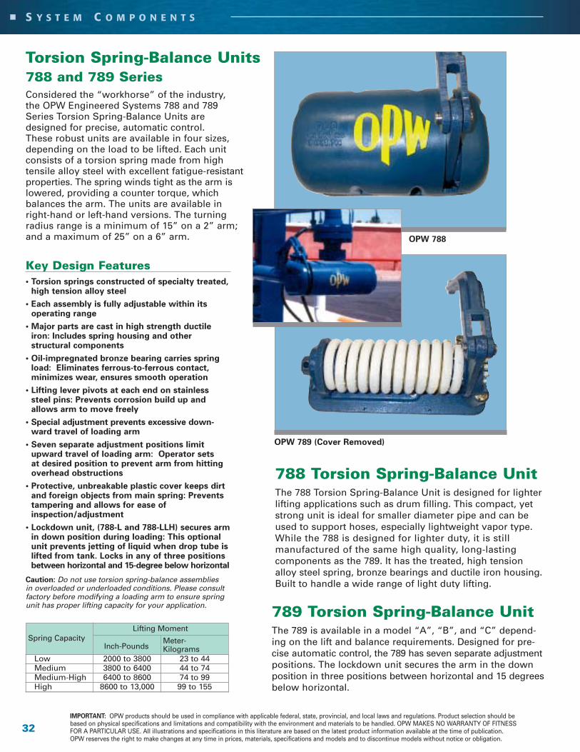
Torsion Spring-Balance Units788 and 789 SeriesConsidered the “workhorse” of the industry,the OPW Engineered Systems 788 and 789Series Torsion Spring-Balance Units aredesigned for precise, automatic control.These robust units are available in four sizes,depending on the load to be lifted. Each unitconsists of a torsion spring made from hightensile alloy steel with excellent fatigue-resistantproperties. The spring winds tight as the arm is lowered, providing a counter torque, whichbalances the arm. The units are available in right-hand or left-hand versions. The turning radius range is a minimum of 15” on a 2” arm; and a maximum of 25” on a 6” arm.
Key Design Features • Torsion springs constructed of specialty treated,
high tension alloy steel
• Each assembly is fully adjustable within itsoperating range
• Major parts are cast in high strength ductileiron: Includes spring housing and otherstructural components
• Oil-impregnated bronze bearing carries springload: Eliminates ferrous-to-ferrous contact,minimizes wear, ensures smooth operation
• Lifting lever pivots at each end on stainlesssteel pins: Prevents corrosion build up andallows arm to move freely
• Special adjustment prevents excessive down-ward travel of loading arm
• Seven separate adjustment positions limitupward travel of loading arm: Operator setsat desired position to prevent arm from hittingoverhead obstructions
• Protective, unbreakable plastic cover keeps dirtand foreign objects from main spring: Preventstampering and allows for ease ofinspection/adjustment
• Lockdown unit, (788-L and 788-LLH) secures armin down position during loading: This optionalunit prevents jetting of liquid when drop tube islifted from tank. Locks in any of three positionsbetween horizontal and 15-degree below horizontal
Caution: Do not use torsion spring-balance assembliesin overloaded or underloaded conditions. Please consultfactory before modifying a loading arm to ensure springunit has proper lifting capacity for your application.
32IMPORTANT: OPW products should be used in compliance with applicable federal, state, provincial, and local laws and regulations. Product selection should bebased on physical specifications and limitations and compatibility with the environment and materials to be handled. OPW MAKES NO WARRANTY OF FITNESSFOR A PARTICULAR USE. All illustrations and specifications in this literature are based on the latest product information available at the time of publication.OPW reserves the right to make changes at any time in prices, materials, specifications and models and to discontinue models without notice or obligation.
S Y S T E M C O M P O N E N T S
789 Torsion Spring-Balance UnitThe 789 is available in a model “A”, “B”, and “C” depend-ing on the lift and balance requirements. Designed for pre-cise automatic control, the 789 has seven separate adjustmentpositions. The lockdown unit secures the arm in the downposition in three positions between horizontal and 15 degreesbelow horizontal.
788 Torsion Spring-Balance UnitThe 788 Torsion Spring-Balance Unit is designed for lighterlifting applications such as drum filling. This compact, yetstrong unit is ideal for smaller diameter pipe and can beused to support hoses, especially lightweight vapor type.While the 788 is designed for lighter duty, it is stillmanufactured of the same high quality, long-lastingcomponents as the 789. It has the treated, high tensionalloy steel spring, bronze bearings and ductile iron housing.Built to handle a wide range of light duty lifting.
Low 2000 to 3800 23 to 44Medium 3800 to 6400 44 to 74Medium-High 6400 to 8600 74 to 99High 8600 to 13,000 99 to 155
Lifting Moment
Meter-KilogramsInch-Pounds
Spring Capacity
OPW 789 (Cover Removed)
OPW 788

33PHONE: (800) 547-9393 • (513) 696-1500 • Fax: (800) 245-8536 • (513) 932-9845 Printed in USA 1/05
2726 Henkle Drive • Lebanon, OH 45036 • www.opw-es.com © Copyright 2005, OPW Engineered Systems
S Y S T E M C O M P O N E N T S
S W I V E L J O I N T S
For more information on OPW’s complete swivel line, referto the OPW Engineered Systems Swivel Joints Catalog.
OPW Engineered Systems fabricated and cast ball bearing swiveljoints allow you to construct a metal piping system that permits easymovement in any direction. Moveable, flexible and reliable, OPWEngineered Systems swivels are designed and built to the highestquality standards, including precision machining and 100% penetration welding, with special design features that include:
1) Tight Seals
• O-Rings provide a tight seal without hindering swivel action
• Accurately machined and micro-finished grooves provide for minimal seal wear
• Available in Buna-N, Viton®, EPT, Neoprene, Kalrez® and other seal materials as required
• Teflon® seals are available as spring energized or silcone/Viton®
encapsulated
2) True Ball Bearing Race Alignment
• Body and tail sections are locked together by a double row of ballbearings
• Raceways are machined to precise tolerances
• Double raceway design assures proper alignment and prevents binding caused by temperature changes and heavy radial loads
• Carbon steel swivels have hardened races to maximize load-carryingcapability
3) Protected Bearing Chamber
• Protective inner O-ring seal prevents product from entering bearingchamber
• Outer seal keeps rain, dirt, and other contaminants out
• Both seals hold in lubrication.
4) Long-Life Bearings
• Ball bearings are hardened, precision-ground steel
• Stainless steel swivels have stainless steel bearings
• All OPW swivels are available with stainless steel bearings on special order
5) Easy Lubrication
• All OPW swivels are pre-lubricated at the factory
• All 3/4", 1", and submerged swivels are permanently lubricated
• A grease fitting between races that accepts a standard grease gun isavailable for swivels that require field lubrication
• Non-lubricating swivels are available on special order
6) No Field Adjustment Necessary
• Balls are held in place by factory-installed plugs that never need to be adjusted to maintain bearing performance
Convenience of Choice
• Available in a variety of sizes beginning at 3/4" and up
• Available in threaded, flanged, and butt welded ends
• Steam jacketed and split flange swivels are also available
Fabricated Steel and Stainless Steel
Cast High-Pressure Steel (Main Sealhas Teflon® Back-up Ring)
Cast Stainless Steel, Aluminum,Ductile Iron, Bronze
3
2
4
15
6
1
34IMPORTANT: OPW products should be used in compliance with applicable federal, state, provincial, and local laws and regulations. Product selection should bebased on physical specifications and limitations and compatibility with the environment and materials to be handled. OPW MAKES NO WARRANTY OF FITNESSFOR A PARTICULAR USE. All illustrations and specifications in this literature are based on the latest product information available at the time of publication.OPW reserves the right to make changes at any time in prices, materials, specifications and models and to discontinue models without notice or obligation.
S Y S T E M C O M P O N E N T S
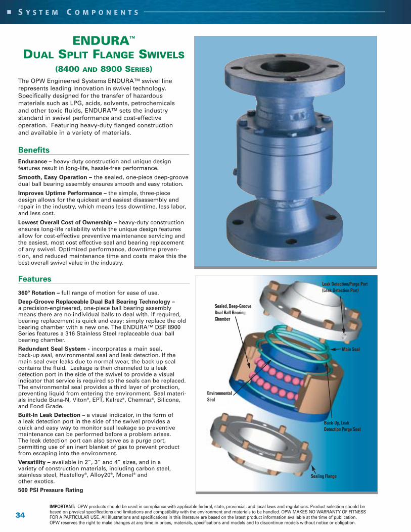
ENDURA™
DUAL SPLIT FLANGE SWIVELS(8400 AND 8900 SERIES)
The OPW Engineered Systems ENDURA™ swivel line represents leading innovation in swivel technology.Specifically designed for the transfer of hazardous materials such as LPG, acids, solvents, petrochemicals and other toxic fluids, ENDURA™ sets the industry standard in swivel performance and cost-effective operation. Featuring heavy-duty flanged construction and available in a variety of materials.
Benefits
Endurance – heavy-duty construction and unique design features result in long-life, hassle-free performance.
Smooth, Easy Operation – the sealed, one-piece deep-groovedual ball bearing assembly ensures smooth and easy rotation.
Improves Uptime Performance – the simple, three-piecedesign allows for the quickest and easiest disassembly andrepair in the industry, which means less downtime, less labor,and less cost.
Lowest Overall Cost of Ownership – heavy-duty constructionensures long-life reliability while the unique design featuresallow for cost-effective preventive maintenance servicing andthe easiest, most cost effective seal and bearing replacementof any swivel. Optimized performance, downtime preven-tion, and reduced maintenance time and costs make this thebest overall swivel value in the industry.
Features
360º Rotation – full range of motion for ease of use.
Deep-Groove Replaceable Dual Ball Bearing Technology –a precision-engineered, one-piece ball bearing assemblymeans there are no individual balls to deal with. If required,bearing replacement is quick and easy; simply replace the oldbearing chamber with a new one. The ENDURA™ DSF 8900Series features a 316 Stainless Steel replaceable dual ballbearing chamber.
Redundant Seal System - incorporates a main seal,back-up seal, environmental seal and leak detection. If themain seal ever leaks due to normal wear, the back-up seal contains the fluid. Leakage is then channeled to a leak detection port in the side of the swivel to provide a visual indicator that service is required so the seals can be replaced.The environmental seal provides a third layer of protection,preventing liquid from entering the environment. Seal materi-als include Buna-N, Viton®, EPT, Kalrez®, Chemraz®, Silicone,and Food Grade.
Built-In Leak Detection – a visual indicator, in the form of a leak detection port in the side of the swivel provides a quick and easy way to monitor seal leakage so preventivemaintenance can be performed before a problem arises. The leak detection port can also serve as a purge port, permitting use of an inert blanket of gas to prevent productfrom escaping into the environment.
Versatility – available in 2”, 3” and 4” sizes, and in a variety of construction materials, including carbon steel, stainless steel, Hastelloy®, Alloy20®, Monel® and other exotics.
500 PSI Pressure Rating
Sealing Flange
Leak Detection/Purge Port(Leak Detection Port)
Sealed, Deep-Groove Dual Ball BearingChamber
Main Seal
Environmental Seal
Back-Up, Leak Detection Purge Seal

35PHONE: (800) 547-9393 • (513) 696-1500 • Fax: (800) 245-8536 • (513) 932-9845 Printed in USA 1/05
2726 Henkle Drive • Lebanon, OH 45036 • www.opw-es.com © Copyright 2005, OPW Engineered Systems
S Y S T E M C O M P O N E N T S
Loading ValvesOPW Engineered Systems Loading Valves are designed toshut off the flow without causing damaging shock in thepipeline. Pipeline shock, or “hammer,” causes problems withpipe joints and instruments in the line. Fast, shocklessclosing is assured by use of an adjustable needle valve, anda dashpot. Air cannot be trapped in the valve so the valvedoes not open after closure. This variable closure rate controlsshock with minimum afterflow. Loading valves are available in several styles to fill almost any liquid transfer requirementwhere versatility and ease of operation are desired.
6400 Series
The 6400 series horizontal loading valve, made in cast aluminum, is “soft closing” in order toreduce line shock. The valve connections aretank-truck (TTMA) flanges. The sturdy valve has a“deadman” feature that requires the operator tohold the handle in the open position whileloading. The trim inside the body is stainless steel,which means this valve can be used for a variety ofchemicals and fuels. Available seals are Buna-N,Ethylene Propylene or Viton® for versatility inhandling a wide range of fluids within theparameters of the body and trim limits.Available in 3”and 4” sizes.
4600 Series (Not Pictured)
The 4600 series horizontal loading valve, made incast aluminum, has bronze trim inside the body,making this valve a good value when handling lessaggressive liquids. Available seals are Buna-N orViton® for fluid compatibility. End connection configurations are threaded. It has the “deadman”feature that requires the operator to hold the handle in the open position while loading. Available in 2” only.
6500 Series
The 6500 series angle loading valve, made in cast aluminum, allows fluid to be held in the line out to the end of the loading arm. The aluminum body is constructed with stainless steel trim for a range of fluidhandling capabilities. It has the “deadman” feature thatrequires the operator to hold the handle in the openposition while loading. End connections are femalepipe thread by TTMA flange. Available in 3” and 4”.
5600 Series (Not Pictured)
The 5600 series angle loading valve, made in cast aluminum with bronze trim, handles petroleum products easily while providing many years of servicelife. It allows fluid to be held in the line out to the end of the loading arm. It has the “deadman” feature thatrequires the operator to hold the handle in the openposition while loading. End connections are female pipethreads. Available in 2” with Buna-N or Viton® seals.
6400 SeriesHorizontal Valve
6500 Series90º Valve
Vacuum BreakersOPW Engineered SystemsVacuum Breakers for high-pressureapplications permit quick, positiveevacuation of the arm after theloading operation is complete. A three-hole quill extends into the liquid passage, forcing theflow pressure to hold the poppetclosed while loading. This prevents aeration of the productand leakage during loading.Liquid trapped in the arm wouldadd extra weight to the arm, causing it to move slowly. The476SA model is available in aluminum with stainlesssteel internal parts. The 489 model is stainless steel forsevere applications and tough liquids.
• Aluminum – Viton®
• SST – Metal Seats
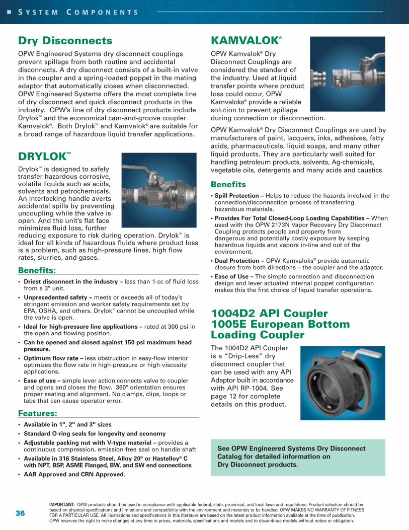
Dry DisconnectsOPW Engineered Systems dry disconnect couplings prevent spillage from both routine and accidental disconnects. A dry disconnect consists of a built-in valvein the coupler and a spring-loaded poppet in the matingadaptor that automatically closes when disconnected.OPW Engineered Systems offers the most complete lineof dry disconnect and quick disconnect products in theindustry. OPW’s line of dry disconnect products includeDrylok™ and the economical cam-and-groove couplerKamvalok®. Both Drylok™ and Kamvalok® are suitable fora broad range of hazardous liquid transfer applications.
DRYLOK™
Drylok™ is designed to safelytransfer hazardous corrosive,volatile liquids such as acids,solvents and petrochemicals.An interlocking handle avertsaccidental spills by preventinguncoupling while the valve isopen. And the unit’s flat faceminimizes fluid loss, furtherreducing exposure to risk during operation. Drylok™ isideal for all kinds of hazardous fluids where product lossis a problem, such as high-pressure lines, high flowrates, slurries, and gases.
Benefits:• Driest disconnect in the industry – less than 1-cc of fluid loss
from a 3" unit.
• Unprecedented safety – meets or exceeds all of today’sstringent emission and worker safety requirements set byEPA, OSHA, and others. Drylok™ cannot be uncoupled whilethe valve is open.
• Ideal for high-pressure line applications – rated at 300 psi inthe open and flowing position.
• Can be opened and closed against 150 psi maximum headpressure.
• Optimum flow rate – less obstruction in easy-flow interioroptimizes the flow rate in high-pressure or high-viscosityapplications.
• Ease of use – simple lever action connects valve to couplerand opens and closes the flow. 360º orientation ensuresproper seating and alignment. No clamps, clips, loops ortabs that can cause operator error.
Features:• Available in 1", 2" and 3" sizes
• Standard O-ring seals for longevity and economy
• Adjustable packing nut with V-type material – provides a continuous compression, emission-free seal on handle shaft
• Available in 316 Stainless Steel, Alloy 20® or Hastelloy® Cwith NPT, BSP, ASME Flanged, BW, and SW end connections
• AAR Approved and CRN Approved.
36IMPORTANT: OPW products should be used in compliance with applicable federal, state, provincial, and local laws and regulations. Product selection should bebased on physical specifications and limitations and compatibility with the environment and materials to be handled. OPW MAKES NO WARRANTY OF FITNESSFOR A PARTICULAR USE. All illustrations and specifications in this literature are based on the latest product information available at the time of publication.OPW reserves the right to make changes at any time in prices, materials, specifications and models and to discontinue models without notice or obligation.
S Y S T E M C O M P O N E N T S
KAMVALOK®
OPW Kamvalok® DryDisconnect Couplings are considered the standard of the industry. Used at liquidtransfer points where productloss could occur, OPWKamvaloks® provide a reliablesolution to prevent spillageduring connection or disconnection.
OPW Kamvalok® Dry Disconnect Couplings are used bymanufacturers of paint, lacquers, inks, adhesives, fattyacids, pharmaceuticals, liquid soaps, and many otherliquid products. They are particularly well suited for handling petroleum products, solvents, Ag-chemicals, vegetable oils, detergents and many acids and caustics.
Benefits • Spill Protection – Helps to reduce the hazards involved in the
connection/disconnection process of transferringhazardous materials.
• Provides For Total Closed-Loop Loading Capabilities – Whenused with the OPW 2173N Vapor Recovery Dry DisconnectCoupling protects people and property from dangerous and potentially costly exposure by keeping hazardous liquids and vapors in-line and out of the environment.
• Dual Protection – OPW Kamvaloks® provide automatic closure from both directions – the coupler and the adaptor.
• Ease of Use – The simple connection and disconnectiondesign and lever actuated internal poppet configurationmakes this the first choice of liquid transfer operations.
1004D2 API Coupler1005E European BottomLoading CouplerThe 1004D2 API Coupler is a “Drip-Less” dry disconnect coupler that can be used with any APIAdaptor built in accordancewith API RP-1004. Seepage 12 for completedetails on this product.
See OPW Engineered Systems Dry Disconnect
Catalog for detailed information on
Dry Disconnect products.

37PHONE: (800) 547-9393 • (513) 696-1500 • Fax: (800) 245-8536 • (513) 932-9845 Printed in USA 1/05
2726 Henkle Drive • Lebanon, OH 45036 • www.opw-es.com © Copyright 2005, OPW Engineered Systems
S Y S T E M C O M P O N E N T S
GT SERIES SAFETY BREAKAWAYThe OPW Engineered Systems Safety BreakawayCoupling is designed specifically to provide protection of equipment and people in the eventof a drive-away/pull-away event.Utilizing an innovative double-poppet design, the OPW Safety Breakaway shuts off the flow of liquid in both directions when separated, providing optimum safety during the transfer ofhazardous products such as LPG, acids, solvents,petrochemicals, gasses, and other toxic liquids.
Benefits• Added Protection of People, Equipment and
the Environment – Double-poppet design automatically shuts off both ends of fluid flow whenseparated, and since it is designed to separate at anyangle when subjected to a designated pull force, thebreakaway saves expensive equipment from damage.
• Durable and Reusable – Available in a variety ofmaterials, this rugged breakaway can be rebuilt forcontinued use after a separation.
• High Flow Rate – Utilizing a straight-line design, theOPW Safety Breakaway provides minimum flowrestriction or pressure drop to deliver the ideal solu-tion for high-flow applications.
Features• Available in a variety of sizes in 316L Stainless Steel,
Aluminum, Alloy 20® and Hastelloy® C.
• Choice of End Connections – NPT, BSP, ASME,Flange, and Butt Weld.
• Order To Specification – Designed to absorbnormal line shock from external overload, shear boltscan be supplied in a variety of sizes and materials tomeet specific pressure and load requirements.
• Rebuild Kits Available – Coupling can be rebuilt, resetand returned to operation. US Patent #5,699,823; EU Patent #0764809; German Patent #69620525-68
Styles mayvary bysize andmaterial
SERIES CONSTRUCTION BREAK END DESIGNATION MATERIALS DIAMETER CONNECTIONS SIZE SEAL
GT Body Example: A – ASME Flange 150 lbs. 020 – 2" B – Viton®-B6 – Aluminum 120 (.120 in.) B – Female BSP C – Viton®-E7 – 316 Stainless Steel 130 (.130 in.) D – DIN Flange E – EPDM8 – Alloy 20® 150 (.150 in.) N – Female NPT V – Viton®-A
9 – Hastelloy C® T – ASME Flange 300 lbs. Y – Kalrez® 4079Studs W – Butt Weld Ends Z – Kalrez® 63756 – Aluminum AN – 150 FlangeX Female7 – 316 Stainless Steel NPT 8 – Alloy 20® (Specify Each End)
9 – Hastelloy C®
Example: GT 7 7 120 N A 020 V
Ordering Specifications

DeflectorsTo prevent static build-up, foaming,impingement on the bottom of thetank, and to keep the drop pipefrom rising, OPW EngineeredSystems manufactures both T-styleand cone-type deflectors. Availablein 2" through 6" sizes, the standardproduct is made of aluminum.Other materials of construction areavailable to meet the needs ofmore corrosive chemicals.
38IMPORTANT: OPW products should be used in compliance with applicable federal, state, provincial, and local laws and regulations. Product selection should bebased on physical specifications and limitations and compatibility with the environment and materials to be handled. OPW MAKES NO WARRANTY OF FITNESSFOR A PARTICULAR USE. All illustrations and specifications in this literature are based on the latest product information available at the time of publication.OPW reserves the right to make changes at any time in prices, materials, specifications and models and to discontinue models without notice or obligation.
S Y S T E M C O M P O N E N T S
OPW-ES 363 – Cast aluminumwith female threads for 2" or6” liquid loaders used ongravity discharge lines.Available in 2" and 6".
OPW-ES 463 – Cast aluminumwith female threads for 3" or 4"liquid loaders. Vertical wingribs help drop tube from risingwhen filling. Acceleratesdischarge and prevents roilingof product when used onpressure discharge line.Available in 3" and 4".
OPW-ES 464 – Cast aluminumtee with female threads.Especially designed for handlingjet fuel. Prevents high velocityimpingement on bottom of tankto reduce possibility of ignitionof jet fuel. Available in 3" and 4".
Visi-Flo® Sight Flow IndicatorsOPW Engineered Systems offers a complete line of sightflow indicators, including the popular Visi-Flo® series,full-view series, and sight windows.
OPW’s sight flow indicators provide a quick, reliable andinexpensive way to verify flow rate and direction, andmonitor color and clarity in fluid lines.
Available in a variety of sizes, styles and materials for awide range of industrial applications, all OPW sight flowindicators carry ASME ratings to ensure maximum reliabilityin harsh operating conditions.
StrainersOPW strainers are used on suction lines when unloading tank cars to prevent scaleand other foreign objects from being sucked into the line. This aluminum cast productis designed with legs on the outlet to keep the inlet off the bottom of the tank. It hasa galvanized screen which is 4-mesh steel. The inlet is standard internal pipe threads.Available in 3" and 4" sizes.
OPW-ES 341

The 8460 Opti-Therm Overfill Detection System recognizes the signal technology, optic or thermistor type onthe transport, verifies grounding, and communicates with the terminal automation system (T.A.S.). The systemenables maximum flexibility at the loading terminal without compromising safety.
39PHONE: (800) 547-9393 • (513) 696-1500 • Fax: (800) 245-8536 • (513) 932-9845 Printed in USA 1/05
2726 Henkle Drive • Lebanon, OH 45036 • www.opw-es.com © Copyright 2005, OPW Engineered Systems
S Y S T E M C O M P O N E N T S
Rack MonitorsOPW Engineered Systems supplies a complete line of CIVACON™ brand rack monitors used in loading and unloading operations. The monitors can detect the type of sensor, the state of liquid in the tank, an overfill situation and verify the grounding condition.
8580 Diagnostic Opti-Therm• Automatically recognizes the type of overfill system (optic or thermistor
signal technology)
• Diagnostic capabilities including ground verification, permissive status and compartment identification. The mode of operation appears on the L.E.D. screen
• The 8580 high-tech system limits the possibility of errors
• Can be used on systems that include up to twelve optic and eight thermistor sensors
• Superior flexibility and safety because of separate output relays for overfill and ground verification
• Easy to read high-resolution 3”x 5” LED diagnostic display
• Monitors overfill status and signals terminal automation system to shut down
Operating Temperature:- 40ºF to 140ºF (-40ºC to 60ºC)
Input Requirements:120 VAC 60 Hz, 15VA (Standard)240 VAC available
Output Relay Contacts:240 VAC – 5A DPDT
Response Time: 0.5 seconds maximum,dry to wet transition
Electrical Connections: Internal Terminal Strips
Enclosure: NEMA 4 explosion proof,Class 1, Div. 1, Group D
Housing Material:Aluminum
Approximate Weight:Model 8580 – 43 lbs.
Approvals: UL, CUL (Canada); CENELEC (Europe)
SPECIFICATIONS – 8580 DIAGNOSTIC OPTI-THERM
Operating Temperature:-40ºF to 158ºF (-40ºC to 70ºC)
Input Requirements:120 VAC 60 Hz, 15VA (Standard)120 VAC available
Output Relay Contacts:240 VAC – 5A DPDT
Response Time: 0.5 secondsmaximum, dry to wet transition
Electrical Connections:Internal Terminal Strips
Enclosure:NEMA 7 explosion proof
Housing Material: Aluminum
Approximate Weight: 8460 – 32 lbs.
Approvals:Factory Mutual, CSA
SPECIFICATIONS – 8460 SERIES OPTI-THERM
Operating Temperature:-40ºF to 158ºF (-40ºC to 70ºC)
Input Requirements:120 VAC 60 Hz, 15VA (Standard)
Output Relay Contacts:Ground Verified: 240 VAC – 5A DPDTOverfill Permissive: 240 VAC – 5A DPDT
Response Time: 0.5 seconds maximum,dry to wet transition
Electrical Connections:Convenient Terminal Strips
Housing Material:Aluminum & Lexan
The 8460SRC Opti-Therm is a direct replacement chassis for upgrading Scully® ST-6 orBICLOPS® rack monitors with CIVACON™ Opti-Therm technology; automatic switching andinternal ground verification for API optic and thermistor technology, all in one box. Can beused with as many as eight optic or thermistor liquid-level type sensors.
SPECIFICATIONS 8460SRC OPTI-THERM
8460 Opti-Therm
8460SRC Opti-Therm / Scully® Replacement Chassis

40IMPORTANT: OPW products should be used in compliance with applicable federal, state, provincial, and local laws and regulations. Product selection should bebased on physical specifications and limitations and compatibility with the environment and materials to be handled. OPW MAKES NO WARRANTY OF FITNESSFOR A PARTICULAR USE. All illustrations and specifications in this literature are based on the latest product information available at the time of publication.OPW reserves the right to make changes at any time in prices, materials, specifications and models and to discontinue models without notice or obligation.
S Y S T E M C O M P O N E N T S
Operating Temperature:-40ºF to 158ºF (-40ºC to 70ºC)
Input Requirements:120 VAC 60 Hz, 10 VA (Standard)240 VAC version available
Output Relay Contacts:240 VAC – 5A DPDT
Response Time: 0.5 seconds maximum, dry to wet transition
Electrical Connections:Internal Terminal Strips
Enclosure:NEMA 7 explosion proof
Housing Material: Aluminum
Approximate Weight:
8130 – 32 lbs.
Approvals: Factory Mutual, CSA
SPECIFICATIONS – 8100 SERIES OPTIC RACK MONITORS
8130 Series Optic Rack MonitorsThe 8130 Series Optic Rack Monitor can be used with up to eight compatible optic liquid-level sensors or onboard monitors to monitor the status of liquid in transports or other storage tanks.
The 8130 Series uses industry standard optic signal format. A unique pulsed and intrinsically safe electrical signal is generated by the control panel and transmitted to the sensors via a coiled cord and optic format plug.
8300 Series Thermistor Rack MonitorsThe 8300 Series provides automatic warning ofproduct overflow at predetermined levels andwarn of pending overflow conditions.
• Uses the standard thermistor signal format tocommunicate with an onboard control monitoror straight thermistor system on transports.
• Can be used with as many as six (availableoption of eight) thermistor liquid-level sensorsor onboard monitors
• Monitors two-wire Thermo-optic Quick Start™replacement sensors
The 8300 Series is available in two models:8340Explosion-proof Thermistor Monitor with permissive and non-permissive status lights with keyed by-pass switch
8360Explosion-proof Thermistor Monitor with permissive and non-permissive status lights with keyed bypass switch andground verification.
In the 8360 monitor, the overfill detection and ground verification are signaled to the pump control system separately.
Operating Temperature:-40ºF to 158ºF (-40ºC to 70ºC)
Input Requirements:120 VAC 60 Hz, 10 VA (Standard)240 VAC version available
Output Relay Contacts:240 VAC – 5A DPDT
Response Time: 0.5 secondsmaximum, dry to wet transition
Electrical Connections:Internal Terminal Strips
Enclosure:NEMA 7 explosion proof
Housing Material: Aluminum
Approximate Weight:
8340 – 32 lbs
8360 – 32 lbs.
Approvals: Factory Mutual, CSA
SPECIFICATIONS – 8300 SERIES THERMISTOR RACK MONITORS
8130Explosion-proof OpticMonitor with status lightsand by pass switch andground verification. On the8130, the overfill detectionand ground verification aresignaled to the pump con-trol system separately.

41
S Y S T E M C O M P O N E N T S
8030 Series Ground VerificationMonitorThe CIVACON™ model 8030 Ground Verification Monitor is compatiblewith today’s transport ground systems. The monitor is 5 amperage,240 volt relay output for control of terminal automation systems(TAS) or pump control devices when used as a stand-alone system.The monitor is equipped to provide a permissive signal to allow loadrack operation and, if ground is lost, to indicate a non-permissivesignal and shut down the loading operation.
ORDERING SPECIFICATIONS
8030-120 Ground verification monitor with indicator lamps – 120V8030-240 Ground verification monitor with indicator lamps – 240V
OPTIONAL ACCESSORIES
7620-7620 Ground verification plug, dual ball with 30 ft. straight cord7690-7690 Ground verification plug, dual ball with 30 ft. straight cord
& junction box7720-7720 Ground verification clamp with 30 ft. straight cord 7790-7790 Ground verification clamp with 30 ft. straight cord & junction box
Midland Valve ActuatorsOPW Engineered Systems Valve Actuators are state-of-the-art technology for safe and efficient control of loading and unloading.They provide fast, automated emergency shut-off of loading andunloading valves for handling very hazardous chemicals, such aschlorine or ethylene oxide. When connected to external warning sensors such as chemical leak detectors, emergency stop switchesor vibration and motion sensors, the actuators can immediately (less than 3 seconds) minimize operator exposure and EPA/DOT-reportable releases in the event of a leak in the transfer connections.Automated opening and closing of transfer valves keep workers a safe distance from hazardous ladings at all times.
Operating Temperature:-40ºF to 158ºF (-40ºC to 60ºC)
Input Requirements:120 VAC 60 Hz, 10 VA (Standard)240 VAC version available
Output Relay Contacts:240 VAC – 5A
Electrical Connections:Internal Terminal Strips
Enclosure: NEMA 4 explosionproof aluminum housing
Approximate Weight:8030 – 13 lbs. (6 KG)
Approvals:UL/CUL Class I, Division I,Groups C&D
SPECIFICATIONS – 8030 SERIES GROUND VERIFICATION MONITORS
CIVACON™ Cane ProbeCane probes are used to provide overfill detection where a permanentsensor cannot be properly affixed to a tank or rail car. They provide aportable, flexible solution to varying overfill requirements for safetop loading. Cane probes utilize modern, instant-on optic principles.Adjusting the sensor position in the tank easily sets the sensing point.This is accomplished with a large adjustment knob on the cane probe clamp.
Plug and Cord SetsCIVACON™ brand plugs and cords are used with junction boxes to connect theoverfill detection monitor to the tank transport at the terminal. Basically, thereare two types of systems: optic (blue, 6-pin) and thermistor (green, 8-pin).
Universal Clamp Clamp-Type Kamlok-Type

OPW-HSL-4”Bottom loading arms
with OPW-VSL Vapor loading arms and 8500-E.(Liberty Overfill and Grounding monitor)
O P W - R E F E R E N C E S
BULGARIA OPW Complete platformwith: B32RF SS
toploader - Foldingstair and Grounding monitor.
SPAIN
OPW Bottom loadingarms and Liberty Overfilland Grounding monitor.
HUNGARY
44

O P W - R E F E R E N C E S
OPW-HSL-4” - Bottom loading arms with OPW-VSL-4” Vapor loading arm with OPW8500-E Overfill and Grounding monitor mounted on OPW-Skid. (Tanktruck loading)
ITALY
OPW-C32RF-4”Top loading.
(Tanktruck loading)
45
UNITED ARAB EMIRATES OPW-G32F-4” - Bottom loaderstainless steel with electrical
tracing and B13F 4” Stainless steel top loadingarms (Railcar loading and unloading)
POLAND

OPW-V64F-4” - Stainless steeljacketed top loading arm
with 3” vapor recovery. (Chemical tanktruck loading)
O P W - R E F E R E N C E S
OPW-CWH-4”Bottom loadingarms with counter-weights.
(Tanktruck loading)
TURKEY
46
UNITED KINGDOM OPW-LPG set -Steel 3” liquid line
and 2” vapor line. (Tanktruck loading)
SAUDI ARABIA

OPW-J12F-4”Steel jacketed loading arm.
(Sulphur Truck loading)
FRANCE
OPW-E32F-3” Aluminium loading arm.
(Railcar loading)
PAKISTAN
O P W - R E F E R E N C E S
OPW-B13F-3” - Steel toploading arm with OPWplatform including OPWfolding stair and safety cage.
(Bitumen loading)
THE NETHERLANDS
47

Mess- und FördertechnikGwinner GmbH & Co
Flow Computer System MFX_4
M+F is a marketleading manufacturer of fl ow computer systems for custody transfer of oil products.
The MFX_80 was the fi rst electronic temperature compensation system worldwide. Since the days of this pio-neer-product, M+F has developed state of the art fl ow computers for the oil industry.
The brand new MFX_4 Flow Computer is already the 4th generation and will con-tinue to be setting industry standards internationally.
There are more than 10.000 MFX Flow Computers in operation worldwide.
�� ���� ��
�
�
�
�
�
�
�
�
�
�
�
� ��
�
�
�
�
�
�
�
�
�
�
�
�
�
�
�
�
�
�
�
�
�
�
�
�
�
�
Soluciones integrales para terminales de carga y descarga

Mess- und FördertechnikGwinner GmbH & Co
>> programmable screen
>> programmable messages
>> multi language capability
>> for stand-alone and automatic mode
>> user friendly design
>> graphical display
>> operation via soft keys
>> Wiegand ID-card reader integrated (option)
>> magnetic card reader optional (option)
>> transponder integrated (option)>> IP65 (not explosion proof version)
>> EExd (ia) T6 IP65 (Ex-version)
>> EEXd capsulated (Ex-proof)
>> CANopen Field Bus for up to 16 MFX_4 Controller
Interfaces:
>> CANopen Bus 2x
>> Ethernet interface TCP/IP (5 port)
>> RS232 Interface
EX-version
non-EX-version
The MFX_4 Terminal is the Man-Machine Interface (MMI) for the connected Controllers (Meter Modules). It can be configured for different sequencing to support a variety of applications.
Its capability to communicate via TCP/IP and CANopen make the MFX_4 Terminal an ideal device for integrating the Flow Computer System MFX_4 into Automation Systems or IT-solutions. The available OPC-Server furtherly supports this integration into standardised Automation Systems.
MFX_4 Terminal
Soluciones integrales para terminales de carga y descarga

Mess- und FördertechnikGwinner GmbH & CoMFX_4 Controller
EX-version for field installa-
non-EX-version for on-board or field installation (IP65)
non-EX-version for rack moun-ting
>> dual pulse input max. 50 kHz>> temperature compensation API>> pressure compensation>> density calculation (Inline density meter)>> 0/4-20 mA input 2x>> 0/4 - 20 mA output 2x>> digital input 4x>> relay output 12x>> pulse input (additive) 1x>> PT 100 4 wire 2x>> pulse output 2x>> inline blending (max 16 products)>> sequential blending (max 16 products)>> additivation (10 additives)>> meter curve linearisation>> meter factor calculation>> flow control (digital/analog)>> control of pump, valve,..>> overfill controll>> pipeline sequencing>> proportional current 1x>> frequency input 1x (density)
Soluciones integrales para terminales de carga y descarga
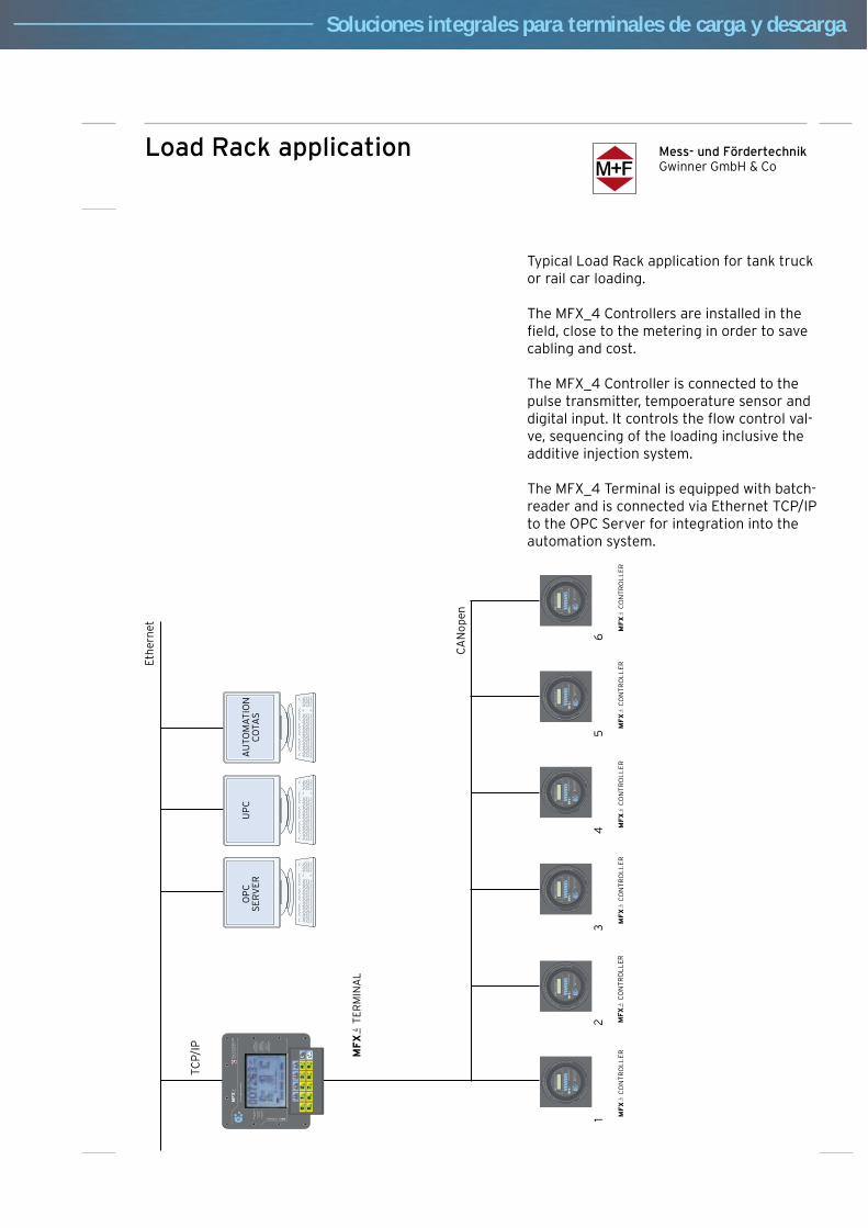
Mess- und FördertechnikGwinner GmbH & Co
Load Rack application
Typical Load Rack application for tank truck or rail car loading.
The MFX_4 Controllers are installed in the field, close to the metering in order to save cabling and cost.
The MFX_4 Controller is connected to the pulse transmitter, tempoerature sensor and digital input. It controls the flow control val-ve, sequencing of the loading inclusive the additive injection system.
The MFX_4 Terminal is equipped with batch-reader and is connected via Ethernet TCP/IP to the OPC Server for integration into the automation system.
Soluciones integrales para terminales de carga y descarga

Mess- und FördertechnikGwinner GmbH & Co
Refueller application
Th
e re
fuel
ler
is e
qu
ipp
ed w
ith
2 m
eter
ing
sys
tem
s.
Th
e M
FX_4
Co
ntr
olle
rs a
re c
on
nec
ted
via
CA
No
pen
to
th
e M
FX_4
Ter
min
al (
MM
I fo
r th
e d
ispa
tch
er).
A s
eco
nd
MFX
_4 T
erm
inal
wit
h G
SM
or
Rad
io L
AN
can
b
e in
stal
led
in t
he
cab
in.
Th
e M
FX_4
Ter
min
al a
lso
pro
vid
es E
ther
net
TC
P/IP
to
o
ther
dev
ices
.
Th
e p
rin
ter
pro
vid
es a
BO
L f
or
the
cust
om
er.
Th
e M
FX_4
Co
ntr
olle
r co
ntr
ols
th
e w
ho
le s
equ
ence
of
th
e re
fuel
ling
(as
wel
l as
the
add
itiv
e in
fect
ion
if
req
uir
ed).
Soluciones integrales para terminales de carga y descarga
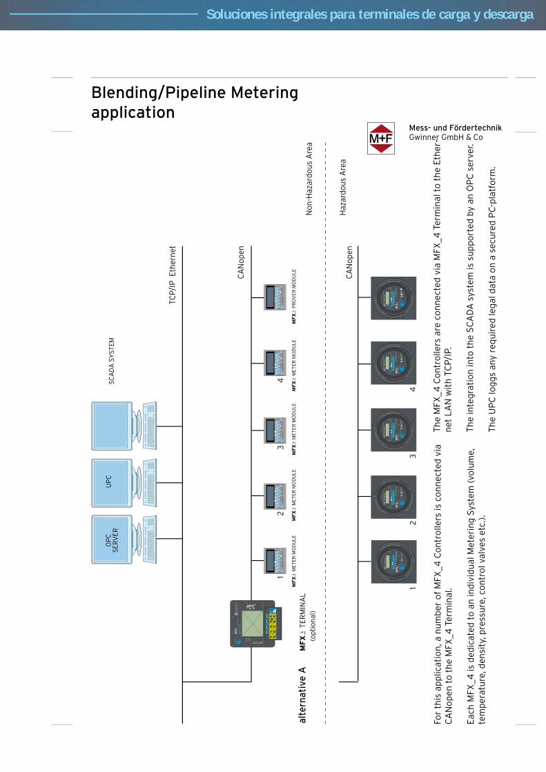
Mess- und FördertechnikGwinner GmbH & Co
12
34
TCP/
IP E
ther
net
CA
Nop
en
alte
rnat
ive
A
alte
rnat
ive
B
CA
Nop
en
(opt
iona
l)
12
34
MFX
P
RO
VER
MO
DU
LE
MFX
P
RO
VE
R M
OD
ULE
Haz
ardo
us A
rea
Non
-Haz
ardo
us A
rea
MFX
T
ERM
INA
L
UP
CS
CA
DA
SY
STE
MO
PC
SE
RV
ER
MFX
M
ETER
MO
DU
LEMFX
M
ETER
MO
DU
LEMFX
M
ETER
MO
DU
LEMFX
M
ETER
MO
DU
LE
MFX
M
ETER
MO
DU
LEMFX
M
ETER
MO
DU
LEMFX
M
ETE
R M
OD
ULE
MFX
M
ETER
MO
DU
LE
Blending/Pipeline Meteringapplication
For
this
ap
plic
atio
n, a
nu
mb
er o
f M
FX_4
Co
ntr
olle
rs is
co
nn
ecte
d v
ia
CA
No
pen
to
th
e M
FX_4
Ter
min
al.
Eac
h M
FX_4
is d
edic
ated
to
an
ind
ivid
ual
Met
erin
g S
yste
m (
volu
me,
te
mp
erat
ure
, den
sity
, pre
ssu
re, c
on
tro
l val
ves
etc.
).
Th
e M
FX_4
Co
ntr
olle
rs a
re c
on
nec
ted
via
MFX
_4 T
erm
inal
to
th
e E
ther
-n
et L
AN
wit
h T
CP/
IP.
Th
e in
teg
rati
on
into
th
e S
CA
DA
sys
tem
is s
up
po
rted
by
an O
PC
ser
ver.
Th
e U
PC
log
gs
any
req
uir
ed le
gal
dat
a o
n a
sec
ure
d P
C-p
latf
orm
.
Soluciones integrales para terminales de carga y descarga

Mess- und FördertechnikGwinner GmbH & Co
Flow Computer MFX_4 in the Truck Loading Terminal
Soluciones integrales para terminales de carga y descarga
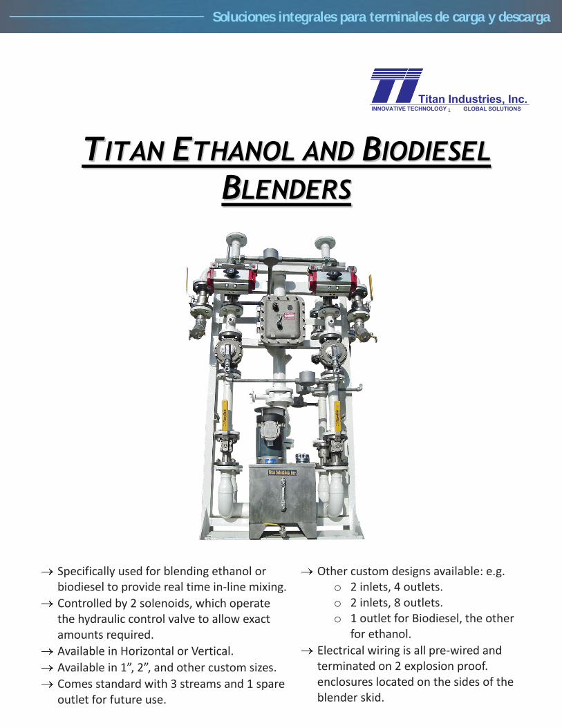
TTIITTAANN EETTHHAANNOOLL AANNDD BBIIOODDIIEESSEELL
BBLLEENNDDEERRSS
Specifically used for blending ethanol or biodiesel to provide real time in-line mixing.
Controlled by 2 solenoids, which operate the hydraulic control valve to allow exact amounts required.
Available in Horizontal or Vertical.
Available in 1”, 2”, and other custom sizes.
Comes standard with 3 streams and 1 spare outlet for future use.
Other custom designs available: e.g. o 2 inlets, 4 outlets. o 2 inlets, 8 outlets. o 1 outlet for Biodiesel, the other
for ethanol.
Electrical wiring is all pre-wired and terminated on 2 explosion proof. enclosures located on the sides of the blender skid.
1
Soluciones integrales para terminales de carga y descarga

TYPICAL BLENDER P&ID
SPECIFICATIONS
Dimensions: 42” x 32” x 85”
Weight: 1500 lbs
Inlet: 3” Flange 150#
Outlet: 2” Flange 150#
Hydraulic Pump: 110vac or 230vac
Solenoid: 110vac or 230vac
Flow sensor: 10 to 32 Vdc
Max Op Press: 260 psi
Flowrate: 4 to 92 gal/min
Max Viscosity: 1000 centipoise
Typ. Kfactor: 102.6 pulses/gal
Soluciones integrales para terminales de carga y descarga

1
Microprocessor
CalibrationPort
Outlet 3-WayBall Valve
AdditiveInlet
AdditiveOutlet
Inlet 2-WayBall Valve
Filter
Flowmeter
On-OffSwitch
PushButton
SolenoidControlValve
Soluciones integrales para terminales de carga y descarga
ProPAC - 3

2
IntroductionTitan Industries, Inc. introduced the first PAC-3 injector in 1989. Since that time, the PAC-3 hasenjoyed a reputation as the most accurate and reliable additive injector in the world. The ProPAC-3 injector is the latest addition to the PAC-3 family. Titan engineers totally redesigned the PAC-3 electronics, incorporating additional features that make the ProPAC-3 injector easier to install,program, and use.
General DescriptionThe Titan ProPAC-3 additive injector is specifically designed to batch inject liquid chemicaladditives at petroleum product terminals. The ProPAC-3 incorporates patented hardware andsoftware designed to accurately inject additive, thereby, insuring the additive/product ratio isalways maintained within customer specifications. The ProPAC-3, when properly integrated intoa users control system, can inject within 0.5% accuracy, thereby, attaining an excellentadditive/product ratio. The injector includes features that will provide the highest level of EPAregulatory compliance.
Typical OperationProPAC-3 Proportional Injection ControllerIn its simplest form, the ProPAC-3 requires only AC power, a flow pulse, and pressurizedadditive to operate. Additive supply pressure (125-150 psig) is provided to the inlet ball valve ofthe injector, via a positive displacement additive pump located on or near an additive storagetank. The injection batch begins when the ProPAC-3 microprocessor energizes the normallyclosed solenoid control valve, thereby allowing additive flow to enter the injector through theinlet ball valve. The solenoid is energized when the programmed number of flow pulses has beenaccumulated by the microprocessor. The flow of additive then passes through a positivedisplacement flow meter that generates a DC pulse train to the ProPAC-3 microprocessor, via aHall Effect sensor. This low voltage pulse train represents the volume of additive being injectedinto the product stream. The additive then exits the flow meter and flows through the solenoidcontrol valve, prior to exiting the injector. When the volume of additive through the flow meterequals the programmed volume for each injection batch, the microprocessor terminates power tothe solenoid control valve, thereby terminating the flow of additive through the injector. TheProPAC-3 microprocessor totals the additive injected, totals the product treated, verifies theadditive/product ratio, and is in standby mode, awaiting the next injection batch.
Auto-PAC Automatic Timed Injection Batch ControllerTitan offers a variation of the ProPAC-3 called the Auto-PAC. The Auto-PAC isdesigned for situations where a product pulse signal is not available to pace the injectionprocess. The Auto-PAC injects based on a user programmed time between injectionsand an optional maximum load volume.The Auto-PAC has three programmable injection rates which can be selected by eitheran optional 4 position switch or other remote automation equipment. The Auto-PAC'smaximum load volume and periodic injection features can be combined together to injectfor example 10 cc' every minute for a maximum of 3 gallons of additive. The injectorwould inject 10 cc's every minute for approximately 19 hours then shut down the pumpat the completion of the load. All ProPAC-3 shutdowns and alarms that are applicableare implemented in the Auto-PAC, and all Auto-PAC injectors can be upgraded to aProPAC-3 injector simply by inserting a new microprocessor display unit.
Soluciones integrales para terminales de carga y descarga
3
Primary System ComponentsMicroprocessor - The ProPAC-3 utilizes a state-of-the-art high speed microprocessor.The microprocessor provides all the operational, alarm, and communication functions forthe injector. The microprocessor incorporates a large graphical display that displays allload, alarm, and programming information. Injectors can be upgraded from Auto-PAC toProPAC-3 simply by replacing this unit.
Mother Board - The vertically mounted mother board serves as a terminating point forall the injector inputs and outputs. The microprocessor, all wiring, and optically isolatedI/O modules plug into the mother board making access easy and I/O configurationchanges possible in the field.
Positive Displacement Flow Meter - The ProPAC-3 incorporates a patented positivedisplacement gear type flow meter. The meter is highly reliable, easy to service andaccurate to within 0.05% of rate. The ProPAC-3 flowmeter uses two rotating impellersdriven by the additive flow through the meter. Each pocket formed between the lobesand the case of the meter forms a known volume. Magnets embedded in the impellerlobes are sensed by a non-intrusive Hall Effect sensor. As the magnets pass the sensor,a 12 VDC pulse train is generated and sent to the microprocessor. The meter body andgears are constructed of 316 stainless steel that will provide many years of accurateand trouble free service.
Solenoid Control Valve - The solenoid control valve is a 2-way, 120 VAC, normallyclosed, direct acting, stainless steel with teflon seat, explosion proof solenoid. Thesolenoid is used to control all additive flow through the injector.
Other ProPAC-3 ComponentsFilter -A 316 stainless steel filter to protect the injector from particulate contamination.The filter contains a 100 mesh stainless steel screen filter element that is easily removedfor servicing.
Check Valve -A check valve is also provided at the injector outlet to prevent productfrom flowing back through the injector. This is an in-line check valve made of 316stainless steel with teflon seat.
On-Off Switch - The two position ON-OFF switch provides electrical control for theinjector. In the OFF position, all electrical power to the injector is removed, except forthe input signals to the injector. In the ON position, the ProPAC-3 will be electricallypowered and the unit will operate automatically on the receipt of the proper input signals.For added security, an optional key lock switch is available. The key lock is lockable inboth the ON and OFF positions.
Push Button - The externally mounted push button has several functions which can beenabled/disable via menu options:
Test injections - By pressing and releasing the push button one timesimulates one injection request, thereby causing the ProPAC-3 to inject.The test injection serves to verify that the ProPAC-3 is working properly.Clear Alarms - When in alarm pressing and releasing the push button willclear the alarm condition, pressing and holding the push button for
Soluciones integrales para terminales de carga y descarga
4
approximately three seconds will clear the alarm and restart the currentlyauthorized load while making up for any additive shortages.Auto Calibration - By pressing and holding the push button is held in forapproximately three seconds, the injector will enter auto-calibration mode.
Features3 Separate Channels for Accumulating Additive and Product Totals - Particularlyhandy for shared additive systems or multiple grade products where the same additive isinjected at different rates. Each additive has a programmable injection rate, Injectionfrequency and Additive meter k-factor, and Text ID for easy identification. Eachchannels additive along with its corresponding product total is stored for individualanalysis. Channel selection is accomplished either via a hardwired permissive input, orvia a software permissive. Each channel maintains accountability for its ownadditive/product ratio.
Graphical Display - The ProPAC-3 incorporates a graphical display that provides theuser with vital information on the injection process. Injector programming is alsosimplified with easy to read programming steps and instructions. Trouble shooting isquick and easy because all the information you need is clearly displayed one screenspecifically related to the current state of the injector.
Loading State Display -While in the load state, the ProPAC-3 displays aLoad Additive Total, Load Product Total, and a batch total for eachinjection. These load totals start at zero and totalize until the permissiveis removed, resulting in a run-time display of the total additive and producttreated per truck.Idle State Display - In the idle state, the Titan ProPAC-3 displays theAdditive Total for each channel as well as a Grand Additive and ProductTotal.Alarm State Display - In alarm state, the ProPAC-3 displays an alarmscreen that will alternate at five second intervals with any of the otherviewed screens. The alarm screen will show inverted colors from normal,thereby making an alarm more noticeable to terminal personnel.Programming Display - In program state, the ProPAC-3 displays a smallsection of the program menu. Push buttons on the microprocessor allowthe user to scroll through the menu and change programmed values.
Simplified Injector Calibration - The ProPAC-3 is equipped with an automaticcalibration mode. All calibration calculations are performed by the ProPAC-3, thuseliminating the possibility of calculation errors. To calibrate the ProPAC-3, simply pushand hold the test injection button on the injector for approximately three seconds, andfollow the on-screen instructions. Each additive should be calibrated to provide the mostaccurate additive injection.
Frequency Line Flush - For dye injection or Clean Start of diesel or gasoline additives itis often necessary to flush the product line clear of additive so that the next truck doesnot receive any of the previously loaded additive. The ProPAC-3 has a unique featurewhich allows the injector to detect the decrease in the product flow rate at the on set oflow flow shutdown. The line flush is accomplished by allowing unadditized product toflow through the line at the end of each compartment load.
Soluciones integrales para terminales de carga y descarga

4” BiRotorModels B080, B081, B083, B084, B085, B088
DescriptionThe BiRotor Meter is a positive displacement meterutilized in the most demanding applications requiringaccuracy, long life and ruggedness. The electronic “P”Series meter configuration features a sealed measuringchamber with one reluctance type electronic sensor.The sealed electronic sensor transmits amplifiedsignals to local or remote instruments. A secondoptional sensor is available to allow dual channelpulses that are 90 degrees electrically out of phase.Accuracy is attained by the unique BiRotor designwhich features two finely balanced rotors. An adjustor,incorporated on the meter, is used to assure maximumaccuracy within the meter's flow range (MechanicalOnly).Long Life is assured because the meter does notcontain any oscillating, reciprocating, sliding parts orcranks to wear or disturb the balanced rotary action. Inaddition, the materials incorporated within the meterassembly are selected specifically for a wide range ofpetroleum and industrial liquid applications.Electrical Classification (P-Style)Class 1, Groups C & D, Division 1, Explosion proof;Recommended connecting cables Belden 8770, 3Conductor Shielded, 18 gauge stranded. Maximumrecommended cable length 3000 feet (914 meters).Input power: 6-28 Vdc at 20 mA, Output Signal: TTL (0-5V) or voltage dependent.Principle of OperationTwo spiral fluted rotors within the measuring unit aredynamically balanced to minimize bearing wear. (Referto Figure 1). As the product enters the intake of themeasuring unit, the two rotors divide the product intoprecise segments of volume momentarily and thenreturn these segments to the outlet of the measuringunit. During this “liquid transition”, the rotation of thetwo rotors is directly proportional to the flow rate of theliquid thruput. A gear train located outside themeasuring unit chamber conveys mechanical rotation
of the rotors to a mechanical or electronic register fortotalization of liquid thruput. For P-Style units, a pulseverification gear located outside the measuring unitchamber conveys mechanical rotation of the rotors tothe sensor and to the electronic register for totalizationof liquid thruput.Design Features• Extremely long service life• Economical low maintenance• Two simple rotors with no metal-to-metal contact are the only moving parts in the measuring chamber.• No oscillating, reciprocating or sliding parts or cranks to wear or disturb the balanced rotary action.• Conforms with International standards of flowmeter accuracy.Accessories (Mechanical)• Preset Counters • Pulse Transmitters• Control Valves • Ticket Printers• Large Numerical Registers • Strainers
Accessories (P-Style)• Electronic Register• Preamp• Dual Pickoffs for “B” Level PulseSecurity
Flow Capacity600 GPM
2,271 LPM857 BPH
*IntermittentFlow Capacity
800 GPM3,028 LPM1,142 BPH
WARNING
Do NOT operate this instrument in excess of the specifications listed. Failure to heed this warning could result in serious injury and/or damage to the equipment.
*5 hours or less in a 24 hour period
Soluciones integrales para terminales de carga y descarga
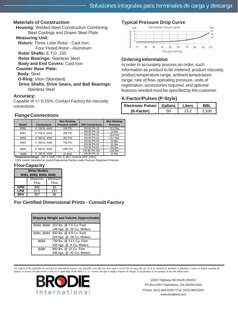
For Certified Dimensional Prints - Consult Factory
Typical Pressure Drop Curve
Ordering InformationIn order to accurately process an order, suchinformation as product to be metered, product viscosity,product temperature range, ambient temperaturerange, rate of flow, operating pressure, units ofregistration, accessories required, and optionalfeatures needed must be specified by the customer.
Materials of Construction Housing: Welded Steel Construction Combining
Steel Castings and Drawn Steel Plate Measuring Unit: Rotors: Three Lobe Rotor - Cast Iron
Four Fluted Rotor - Aluminum Rotor Shafts: E.T.D. 150 Rotor Bearings: Stainless Steel Body and End Covers: Cast Iron Counter Base Plate: Body: Steel O-Ring: Viton (Standard) Drive Shafts, Drive Gears, and Ball Bearings:
Stainless SteelAccuracy:Capable of +/- 0.15%; Contact Factory for viscositycorrections.
Flange Connections
Flow Capacity
K-Factor/Pulses (P-Style)
Model ConnectionsMax Working
Pressure @100F DIN ConnectionsMax Working
PressureB080 4" 150 lb. ANSI 150 PSI DN 80 PN 16 10.3 Bar
DN 80 PN 16 16 BarDN 80 PN 40 19.6 Bar
B083 4" 300 lb. ANSI 300 PSI DN 80 PN 40 20.7 BarDN 80 PN 40 40 BarDN 80 PN 64 51 BarDN 80 PN 64 64 BarDN 80 PN 100 100 Bar
*B088 4" 150 lb. ANSI 10 BAR DN 80 PN 16 10 BarTemperature Range : -20F to 150F (-29C to 66C) Optional 450F (232C)*150# meters Classified as Sound Engineering Practice under Pressure Equipment Directive
B084 4" 300 lb. ANSI 740 PSI
B085 4" 600 lb. ANSI 1480 PSI
B081 4" 150 lb. ANSI 285 PSI
Electronic Pulses Gallons Liters BBL(K-Factor) 50 13.2 2,100
Maximum Flow
Minimum Flow
GPM 600 60LPM 2271 227BPH 857 86
Meter ModelsB081, B083, B084, B085
B080, B088 323 lbs. @ 7.0 Cu. Feet146 kgs. @ .20 Cu. Meters
B081, B083 450 lbs. @ 9.8 Cu. Feet204 kgs. @ .28 Cu. Meters
B084 739 lbs. @ 14.1 Cu. Feet335 kgs. @ .4 Cu. Meters
B085 960 lbs. @ 15 Cu. Feet435 kgs. @ .42 Cu. Meters
Shipping Weight and Volume (Approximate)
The contents of this publication are presented for informational purposes only, and while every effort has been made to ensure their accuracy, they are not to be construed as warranties or guarantees, express or implied, regarding theproducts or services described herein or their use or applicability. Brodie Meter Co., LLC reserves the right to modify or improve the designs or specifications of such products at any time without notice.
19267 Highway 301 North (30461)PO Box 450 • Statesboro, GA 30459-0450
Phone: (912) 489-0200 • Fax: (912) 489-0294www.brodieintl.com
Soluciones integrales para terminales de carga y descarga
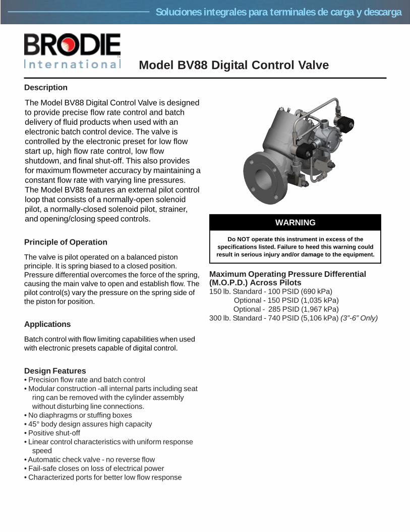
Model BV88 Digital Control Valve
Description
The Model BV88 Digital Control Valve is designedto provide precise flow rate control and batchdelivery of fluid products when used with anelectronic batch control device. The valve iscontrolled by the electronic preset for low flowstart up, high flow rate control, low flowshutdown, and final shut-off. This also providesfor maximum flowmeter accuracy by maintaining aconstant flow rate with varying line pressures.The Model BV88 features an external pilot controlloop that consists of a normally-open solenoidpilot, a normally-closed solenoid pilot, strainer,and opening/closing speed controls.
Principle of Operation
The valve is pilot operated on a balanced pistonprinciple. It is spring biased to a closed position.Pressure differential overcomes the force of the spring,causing the main valve to open and establish flow. Thepilot control(s) vary the pressure on the spring side ofthe piston for position.
Applications
Batch control with flow limiting capabilities when usedwith electronic presets capable of digital control.
Design Features• Precision flow rate and batch control• Modular construction -all internal parts including seat
ring can be removed with the cylinder assemblywithout disturbing line connections.
• No diaphragms or stuffing boxes• 45° body design assures high capacity• Positive shut-off• Linear control characteristics with uniform response
speed• Automatic check valve - no reverse flow• Fail-safe closes on loss of electrical power• Characterized ports for better low flow response
WARNING
Do NOT operate this instrument in excess of the specifications listed. Failure to heed this warning could result in serious injury and/or damage to the equipment.
Maximum Operating Pressure Differential(M.O.P.D.) Across Pilots150 lb. Standard - 100 PSID (690 kPa) Optional - 150 PSID (1,035 kPa)
Optional - 285 PSID (1,967 kPa)300 lb. Standard - 740 PSID (5,106 kPa) (3”-6” Only)
Soluciones integrales para terminales de carga y descarga

Materials of ConstructionMain Valve Body: Steel-ASTM-A216-GR-WCBMain Valve Cylinder: 17-4 Stainless Steel, Heat
TreatedMain Valve Piston: Stainless SteelSeat Ring: Stainless SteelO-Rings: Viton Standard
(Other elastomers available)Other Internal Parts: Stainless SteelPilot Valve Strainer/Needle Valve Strainer:
Standard: SteelTubings and Fittings: Standard: Steel
Dimensions (For Certified DimensionalPrints - Consult Factory)
Flange Connections
Standard Equipment• Opening and closing speed controls• Self-cleaning strainer (Pilot Inlet)• Stainless steel solenoid pilotsOptional Equipment• Manual Override• Thermal ReliefRecommended Spare PartsO-Rings
Ordering InformationIn order to accurately process an order, suchinformation as product to be controlled, productviscosity, product temperature range, ambienttemperature range, rate of flow, operating pressure,and optional features needed must be specified by thecustomer.
Valve Size ConnectionsMax Working Pressure
@100F2"-6" 150 lb. ANSI 285 PSI3"-6" 300 lb. ANSI 740 PSI
Temperature Range : -20F to 150F (-29C to 66C) Optional 250F (121C)
2" 69 lbs. @ 3 Cu. Feet31.3 kgs. @ .085 Cu. Meters
3" 105 lbs. @ 2.36 Cu. Feet47.63 kgs. @ .067 Cu. Meters
4" 140 lbs. @ 2.51 Cu. Feet63.5 kgs. @ .071 Cu. Meters
6" 250 lbs. @ 4.84 Cu. Feet113.4 kgs. @ .137 Cu. Meters
Shipping Weight and Volume (Approximate)
mmInches 150 lb. 300 lb.
mm 260 267Inches 10 1/4 10 1/2
mm 279 333Inches 11 13 1/8
mm 330 368Inches 13 14 1/2
mm 432 454Inches 17 17 7/8
4"
6"
B Dimensions150 & 300 lb.
28611 1/4
29211 1/2
34613 3/8
Valve Size
A Dimensions
3"
2" 28011
The contents of this publication are presented for informational purposes only, and while every effort has been made to ensure their accuracy, they are not to be construed as warranties or guarantees, express or implied, regarding theproducts or services described herein or their use or applicability. Brodie Meter Co., LLC reserves the right to modify or improve the designs or specifications of such products at any time without notice.
19267 Highway 301 North (30461)PO Box 450 • Statesboro, GA 30459-0450
Phone: (912) 489-0200 • Fax: (912) 489-0294www.brodieintl.com
Soluciones integrales para terminales de carga y descarga

Design SpecificationsDSSTRAINERS
Revision 05
Strainers In-Line and Angle
Description
Strainers are installed in pipe lines ahead ofmeters, pumps, valves, etc., to protect suchequipment against intrusion of pipe scale,welding spatter and other foreign material. Theuse of the proper size strainer together with abasket of suitable mesh pays dividends inreduced maintenance on mechanisms which arein contact with flowing liquids.
When it is known that comparatively largeamounts of lint or iron oxide are present in astream, a large strainer should be used as thesematerials clog up basket screens rapidly-especially if resins, gums or varnishes are alsopresent.
Larger size foreign matter such as pebbles,welding beads, etc., should be removed atfrequent intervals to prevent their abrasive actionfrom damaging the basket screen.
Strainers are available in sizes 3" to 6" formaximum working pressures to 300 psi (2068kPa). There is a Strainer of the proper size andpressure rating to accommodate the full line ofFlow Meters. For large capacity and highpressure strainers, refer to DSBVBS.
WARNING
Do NOT operate this instrument in excess of the specifications listed. Failure to heed this warning could result in serious injury and/or damage to the equipment.
In-Line Strainer3”, 4”, 6”DA-3-150
Angle Strainer3”, 4”, 6”
DA-3-4-150A
Pressure Loss Handling Gasoline
Soluciones integrales para terminales de carga y descarga

Specifications
Strainer Screen DataStrainer screen material for all strainers is stainless steel.
ANSI Flanges Std.
psi kPa (Except D-2B) Pounds Kilos Cubic Feet
Cubic Meters
DA-3-150 150 1,034 3"-150 lb. 3/4" Std. Pipe Thd. Drawn Steel 45 20.41 1.72 0.049DA-3-4-150 150 1,034 4"-150 lb. 3/4" Std. Pipe Thd. Drawn Steel 55 24.95 1.72 0.049D-6-4-150 150 1,034 4"-150 lb. 1" Std. Pipe Thd. Drawn Steel 135 61.23 6.89 0.195D-6-150 150 1,034 6"-150 lb. 1"Std. Pipe Thd. Drawn Steel 145 65.77 6.89 0.195
Model Strainer Drain Size Housing
Material
Approximate Shipping Cube
Maximum Working Pressure
Approximate Shipping Weight
Model Strainer
Mesh of Screen *
Total Screen Area
Sq. In.
Per Cent Open
Area **
Open Area Sq. In. Size Area
Sq. In.
Total Area to Pipe
Area
Open Area to Pipe
AreaD-3 20 46.2 52.2 7.1:1
DA-3 40 38.4 43.4 5.9:1DA-3A 60 30.5 34.5 4.7:1D-3-4 20 46.2 52.2 4.1:1
DA-3-4 40 38.4 43.4 3.4:1DA-3-4-A 60 30.5 34.5 2.7:1
20 46.2 145.1 11.4:140 38.4 120.6 9.5:160 30.5 95.8 7.5:120 46.2 145.1 5.0:140 38.4 120.6 4.2:160 30.5 95.8 3.3:1
** Percent open area for some special screens is as follows:10 Mesh - 46.2 Percent100 Mesh - 30.3 Percent
Percent open area depends on wire size and may vary slightly.
12.73
D-6 D-6-A
Notes:* Mesh of screen as shown in chart above is standard. Special mesh is available at extra cost when required.
28.89 10.9:1
D-6-4D-6-4-A
3"
4"
4"
113
113
314
Screen Pipe Line Ratio
314 6"
15.3:1
8.9:1
24.7:1
7.393
12.73
Soluciones integrales para terminales de carga y descarga

Dimensions (For Certified Dimensional Prints - Consult Factory)
Basket Dimensions
Inches mm Inches mm Inches mmDA -3, DA-3-4 51/4 133.35 83/4 222.25 37/8 98.42D-6-4, D-6 91/2 241.3 13 330.2 2 50.8
ModelDimensions
G H J
Inches mm Inches mm Inches mm Inches mm Inches mm Inches mmDA-3-150 13 330.2 10 1 /4 260.35 41/2 114.3 15 3/4 400.05 73/8 187.32 83/8 212.72
DA-3-4-150 13 330.2 10 1/4 260.35 41/2 114.3 15 3/4 400.05 73/8 187.32 83/8 212.72D-6-4-150 22 5/8 574.67 16 3/8 415.92 61/4 158.75 25 15/26 658.81 12 3/8 314.32 15 381D-6-150 22 5/8 574.67 16 3/8 415.92 61/4 158.75 25 15/16 658.81 12 3/8 314.32 15 381
D E FStrainer Model A B C
Dimensions - Angle Strainers (For Certified Dimensional Prints - Consult Factory)
Inches mm Inches mm Inches mm Inches mm Inches mm
DA-3-ADA-3-4-A 3" and 4" 150 Ib. 4 7/16 112.71 11 279.4 6 1/2 165.1 16 4/7 420.68 7 1/4 184.15
D-6-4-AD-6-A 4" and 6" 150 Ib. 6 5/16 160.33 17 431.8 11 5/16 287.33 27 5/32 689.77 12 3/8 314.32
Inches mm Inches mm Inches mm Inches mm
DA-3-ADA-3-4-A 3" and 4" 150 Ib. 8 3/8 212.72 5 1/2 139.7 8 11/16 220.66 2 3/4 69.85
D-6-4-AD-6-A 4" and 6" 150 Ib. 15 381 7 1/4 184.15 12 3/4 323.85 15/16 23.81
Model Connector Size
Dimensions
Dimensions
E
G H
Connector SizeModel A C D
F J
B
Soluciones integrales para terminales de carga y descarga

Strainer BasketsTo be efficient, strainer baskets must be kept clean. A buildup of sediment increases pressure drop anddecreases flow. If a basket is allowed to become completely clogged, damage will result. Pressure gaugeson each side of the strainer - or a differential pressure gauge -give an indication of basket condition at aglance.A regular procedure should be set up for cleaning strainer baskets-the frequency depending on amount andcharacter of foreign material in the stream. It is advisable to keep a spare basket (or inner screen) on hand.Recommended Mesh Of Screens For Various Liquids:Gasoline and similar liquids, 60 Mesh for 3”, 4”, and 6” strainers.Diesel Oil, No. 2 Oil, etc. - 40 Mesh No. 5 or No. 6 Heating Oils, etc. - 20 Mesh
Type of Strainer Basket used on DA-3, DA-4, D-3,D-3-4.Three piece strainer basket is quickly disassembledto provide replaceable inner screen.
Type of Strainer, Basket used on D-6, D-6-4. Innerscreen is soldered to basket frame; may bereplaced when required.
DA-3-150The DA-3-150 above illustrates construction of theDA-3-4-150. These strainers have a four bolt coverand use an O-ring as the cover gasket.D-3-300 and D-3-4-300 Strainers are of similarconstruction, but use a flat cover gasket instead ofthe O-ring. The cover also holds the strainer basketin place by means of spring tension.
D-6-150The D-6-150 below illustrates construction of theD-4-150, Strainer. Strainer baskets are held securelyin place by means of wing nuts.
The contents of this publication are presented for informational purposes only, and while every effort has been made to ensure their accuracy, they are not to be construed as warranties or guarantees, express or implied, regarding theproducts or services described herein or their use or applicability. Brodie Meter Co., LLC reserves the right to modify or improve the designs or specifications of such products at any time without notice.
19267 Highway 301 North (30461)PO Box 450 • Statesboro, GA 30459-0450
Phone: (912) 489-0200 • Fax: (912) 489-0294www.brodieintl.com
Soluciones integrales para terminales de carga y descarga

Custody Transfer Mass Flowmeter with single straight measuring tube
OIML R117 Pattern Approval Accuracy classes 0.3 / 0.5 / 1.0 / 1.5
Applications
• Oil, oil products • LNG (propane / butane) loading for rail cars and
tank trucks • Chemical and petrochemical industry • Robust and reliable with simple installation gives
low ’whole life cost of ownership’. • Five sizes available allow best meter selection for
accuracy and pressure loss calculations.
Highlights
• Accuracy class 0.3 The first Single Straight Tube mass flowmeter to achieve this.
• With secondary containment ratings to 100 bar / 1450 psig, this is the preferred meter for hazardous applications.
Technical Datasheet OPTIMASS 7050 CT
Soluciones integrales para terminales de carga y descarga

www.krohne-oilandgas.com 2
Oil & Gas
Example of application: Liquefied natural gas uploading from rail car
Technical Data
Flow rate T15 T25 T40 T50 T80
Nominal flow rate [kg/h] 11250 34500 91500 180000 430000
Nominal flow rate [lbs/min] 400 1250 3300 6600 15800
Flow range [Class 0.3] kg/h 11250 … 1125 34500 … 3450 91500 … 9150 180000 … 18000 430000 … 43000
lbs/min 400 … 40 1250 …125 3300 … 330 6600 … 660 15800 … 1580
Flow range [Class 0.5] kg/h 11250 … 563 34500 … 1725 91500 … 4575 180000 … 9000 430000 … 21500
lbs/min 400 … 21 1250 … 21 3300 … 169 6600 … 333 15800 … 778
Maximum flow rate 130% of nominal flow rate
Minimum flow rate Depending on measuring error required
Definition of OIML R 117 accuracy classes
Class 0.3 Measuring systems on pipelines, sometimes called the pipeline transfer standard, which is required for applications where flows are for long periods of time, e.g. oil transfer between storage tanks or long distance pumping transfer
Class 0.5 All other measuring systems (if not explicitly stated in another class), e.g. loading / unloading of ships, railcars and road tankers
Accuracy Accuracy, liquid (all sizes) ±0.1% of actual measured flow rate
Repeatability Better than 0.05% plus zero stability (includes the combined effects of repeatability, linearity and hysteresis)
Zero stability ±0.008% of nominal flow rate for the sensor size
Reference conditions Product Water
Temperature 20°C / 68°F
Operating pressure 1 barg/ 14.5 psig
Soluciones integrales para terminales de carga y descarga

www.krohne-oilandgas.com 3
Density
Measuring range 500…2000 kg/m3/ 30…125 lbs/ft3
Accuracy ±2 kg/m3/ ±0.13 lbs/ft3
Accuracy (on-site calibration) ±0.5 kg/m3/ ±0.033 lbs/ft3
Temperature
Measuring range -40…+150°C / -40…+302°F
Accuracy ±1°C / ±1.8°F
Materials Measuring tube Titanium Flange raised face Titanium Flanges Stainless steel 1.4435 / AISI 316L Outer cylinder (secondary pressure containment) Stainless steel 1.4301 / AISI 304 (optional: stainless steel 1.4435 / AISI 316L) Sensor electronics housing Stainless steel 1.4435 / AISI 316L Nominal pressure at 20°C or 68°F
Measuring tube -1…63 barg / -14.5…910 psig Outer cylinder (secondary pressure containment) Standard: -1...63 bar / -14.5...910 psig Optional: -1…100 barg. / -14.5…1450 psig Temperature
Process temperature - flanged connections -40…+150°C / -40…+302°F Ambient temperature - compact version -40…+55°C / -40…+130°F Ambient temperature - remote version -40…+60°C / -40…+140°F Process effects on the sensor
Temperature 0.002% of nominal flow rate per 1°C / 0.001% of nominal flow rate per 1°F Pressure 0.015% of nominal flow rate per 1 barrel. / 0.001% of nominal flow rate per 1 psig
Approvals
Mechanical Protection category (acc. to EN 60529) IP 67; NEMA 4X European Pressure Equipment directive
PED 97-23 EC (acc. to AD 2000 Regelwerk)
Hazardous area classifications Sensor only Converter only Compact unit ATEX (acc. to 94/9/EC)
II 2 G EEx ib IIC T6 II 2 G EEx de [ib] IIC T6 (with “increased safety” terminal housing II 2 G EEx d [ib] IIC T6 (with “flameproof” terminal housing
II 2 G EEx de [ib] IIC T6 (with “increased safety” terminal housing II 2 G EEx d [ib] IIC T6 (with “flameproof” terminal housing
Factory Mutual / CSA Class I, Div 1 groups A, B, C, D Class II, Div 1 groups E,F,G Class III, Div 1 hazardous areas Class I, Div 2 groups A, B, C, D Class II, Div 2 groups F,G Class III, Div 2 hazardous areas Custody transfer PTB PTB 5.4.11 04.16 (massflow only) Please contact KROHNE for list of other country approvals Electromagnetic compatibility (EMC) to CE
EN 50081-1 (1992); EN 50082-2 (1994); Namur NE 21/5.95; 89/336/EEC (EMC); 72/73/EEC (Low Voltage Directive)
Calibration On flow rigs accredited by UKAS according to BS/EN/ISO/IEC 17025
Soluciones integrales para terminales de carga y descarga
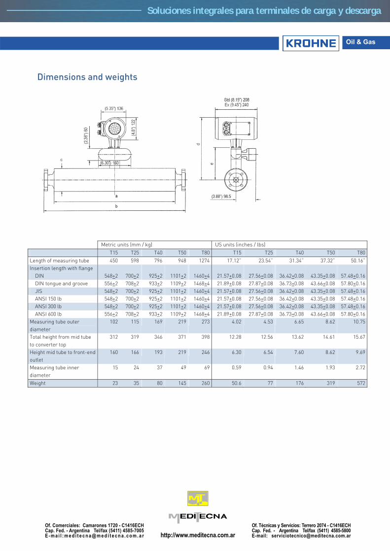
Oil & Gas
Dimensions and weights
Metric units (mm / kg) US units (inches / lbs)
T15 T25 T40 T50 T80 T15 T25 T40 T50 T80
Length of measuring tube 450 598 796 948 1274 17.12” 23.54” 31.34” 37.32” 50.16”Insertion length with flange DIN 548+2
700+2 925+2 1101+2 1460+4 21.57+0.08 27.56+0.08
36.42+0.08 43.35+0.08 57.48+0.16
DIN tongue and groove 556+2 708+2 933+2 1109+2 1468+4 21.89+0.08 27.87+0.08 36.73+0.08 43.66+0.08 57.80+0.16 JIS 548+2 700+2 925+2 1101+2 1460+4 21.57+0.08 27.56+0.08 36.42+0.08 43.35+0.08 57.48+0.16 ANSI 150 lb 548+2 700+2 925+2 1101+2 1460+4 21.57+0.08 27.56+0.08 36.42+0.08 43.35+0.08 57.48+0.16 ANSI 300 lb 548+2 700+2 925+2 1101+2 1460+4 21.57+0.08 27.56+0.08 36.42+0.08 43.35+0.08 57.48+0.16 ANSI 600 lb 556+2 708+2 933+2 1109+2 1468+4 21.89+0.08 27.87+0.08 36.73+0.08 43.66+0.08 57.80+0.16Measuring tube outer diameter
102 115 169 219 273 4.02 4.53 6.65 8.62 10.75
Total height from mid tube to converter top
312 319 346 371 398 12.28 12.56 13.62 14.61 15.67
Height mid tube to front-end outlet
160 166 193 219 246 6.30 6.54 7.60 8.62 9.69
Measuring tube inner diameter
15 24 37 49 69 0.59 0.94 1.46 1.93 2.72
Weight 23 35 80 145 260 50.6 77 176 319 572
Soluciones integrales para terminales de carga y descarga
Soluciones integrales para terminales de carga y descarga