solo plus - heat with wood plus is not a self contained weather-tight boiler. it should be installed...
TRANSCRIPT

Solo Plus Instructions 1-800-782-9927 Version 12-13
Tarm Biomass · 4 Britton Lane · Lyme, NH 03768
SOLO PLUS Models 30, 40, and 60
Installation and Operations Manual
Wood-fired central heating boiler

Solo Plus Instructions 1-800-782-9927 Version 12-13
Tarm Biomass · 4 Britton Lane · Lyme, NH 03768
TABLE OF CONTENTS
Introduction >Table Of Contents Page i
1.0 Introduction…………………………………………………………………………….....1
1.1 Foreword………………………………………………………………………...…1
1.2 Units of Measure……………………………………………………………...……1
1.3 Installation and Warranty Requirements……………………………………..……1
2.0 System Description/Requirements………………..………...…………………...…...….3
2.1 Boiler Overview………………………………………………………………...….3
2.1.1 Cut Away View……………………………………………………….....3
2.1.2 Boiler Fabrication and Testing…….……………………………...……...4
2.1.3 Models and Applications………………………...…………………...….4
2.2 Boiler Function………………………………………………………………….....4
2.2.1 General Operation.…………………………………………………...…..4
2.2.2 Safety Systems……………...………………………………………...….5
2.2.3 Accessories…....…………………………………………………..……..5
2.3 Fuels…………………………………………………………………………...…...6
2.4 Building Requirements………………………………………………………..…...7
2.5 Owner Responsibilities……………………………………………………..….…..7
3.0 Boiler Installation and Startup…………………………………………………...……...8
3.1 Planning…………………………………………………………………………....9
3.1.1 Sizing the Boiler……………………………………………………..…..9
3.1.2 Choosing an Installer……………………………………………..……...9
3.1.3 Locating the Boiler and Boiler Clearances..………………………...…...9
3.1.4 Plumbing and Mechanical……………………………………………....11
3.1.5 Electrical…………………………………………………………….….12
3.2 Preparing the Chimney…………………………………………………………...12
3.2.1 Outside Combustion Air………………………………………………..14
3.3 Setting the Boiler………………………………………………………………....14
3.3.1 Receiving the Boiler……………………………………………...….…14
3.3.2 Boiler Checklist...………………………………………………….…...15
3.3.3 Temporary Storage..………………………………………………....…16
3.3.4 Moving the Boiler……………………………………………………....16
3.3.5 Boiler Set-Up…………………………………………………………...16
3.4 Connections to the Boiler……………………………………………………...…20
3.4.1 Chimney Connection………………………………………………...…20
3.4.2 Safety Plumbing……………….………………………………………..21
3.4.3 Plumbing Connections...……………..…………………….………......22
3.4.4 Pipe Connection-Choice of Material...……………...……………….…24
3.4.5 Expansion Tank…………………………………………...…………....24
3.4.6 Pump Size……………………………………………...…………….…24
3.4.7 Installation of Optional Domestic Hot Water Coil………………….….24
Section Page

Solo Plus Instructions 1-800-782-9927 Version 12-13
Tarm Biomass · 4 Britton Lane · Lyme, NH 03768
Introduction >Table Of Contents Page ii
Section Page
3.4.8 Installing the 339N Probe Thermometer.………...………...…….…….26
3.4.9 Installing the Optional Turbulators…………………..……….………...26
3.4.10 Control Logic……….…………………….………..………..….……..27
3.4.11 Electrical Connections………...…………………………..……...…...30
3.4.12 Boiler Control Panel Connections.…………………………...……….30
3.4.13 Description of Functions……………………………..….….…………30
3.4.14 Operating Thermostat……...………………………..…...…...……….30
3.4.15 Lo-Limit Thermostat.………………………………………...….……30
3.5 Commissioning the Boiler…………...……………………………...……..……..31
3.5.1 Safety Plumbing…………………………………………...…….…..….31
3.5.2 Filling and Venting………………………………………...…….....…..32
3.5.3 Final Installation Checklist………………………………...……..….....32
3.5.4 Combustion and Performance Testing……...…………..………..…….33
4.0 Boiler Operation, Maintenance, and Service……………………………………...…..34
4.1 Control Panel Orientation…………………………………………………..…….34
4.2 Items to Check Before Using……………………………………………..…...….36
4.3 Starting the Boiler…………………………………………………………..…….36
4.4 Adding Wood………………………………………………………...…………...38
4.4.1 Adding Wood When the Draft Fan is OFF (Boiler at Operating Temperature)…..38
4.4.2 Adding Wood When the Draft Fan is OFF (Boiler Temperature below 140ºF (60ºC))....38
4.4.3 Adding Wood When the Draft fan is ON…………………………..…..38
4.5 Daily Firing……………………………………………………………...………..39
4.6 Shutting Down the Boiler………………………………………………..……….40
4.7 Operation with Thermal Storage System……………………………………..…..40
4.8 Creosote………………………………………………………………………......40
4.9 Combustion Process...………………………………………………………...…..41
4.10 Heat Output.……………………………………………………….………...…..41
4.11 Burn time……………………………………………………………………..…41
4.12 Primary Air Adjustment…………………………………………………….…..42
4.13 Secondary Air Adjustment………………………………………………….…..42
4.14 Firing Tips……………………………………………………………………....43
4.15 Operation During Summer……………………………………………………...43
4.16 Cleaning and Maintenance………………………………………….……….….44
4.16.1 Ash Removal……………………………………………….………....44
4.16.2 Smoke Box and Heat Exchanger Tube Cleaning…………………..…45
4.16.3 Cleaning the Draft Fan………….……………………….………..…..45
4.16.4 Maintaining Door Seals…………………………………….……..…..46
4.16.5 Cleaning the Primary Air Duct and Channels…………….……..…....46
4.16.6 Smoke Pipe Inspection and Cleaning……………………….…….…..47
4.16.7 Chimney Fires…………………....………………………….…….….48
4.16.8 Checking the Barometric Damper………………...……………..……48
4.16.9 Cleaning the Jacket………………….………………..….………..…..48
4.11.10 Check for Creosote Build-Up……….…………...…………….…….48
4.11.11 Seasonal Shutdown Procedure…………………….….….…………..48

Solo Plus Instructions 1-800-782-9927 Version 12-13
Tarm Biomass · 4 Britton Lane · Lyme, NH 03768
Introduction >Table Of Contents Page iii
Section Page
4.16.12 Checking the Pressure Relief Valve……………………………....…48
4.16.13 Checking System Pressure…………………………………...…..…..49
4.16.14 Heat Storage System Maintenance………………………………..…49
4.12 Power Outages…………………………………………………………….…….49
5.0 Troubleshooting……………………………………………………………………..…..50
5.1 Troubleshooting Guide………………………………………………………..….50
5.2 Troubleshooting Flow Chart………...………………………………….…..…….51
6.0 Data and Drawings…………………………………………………………………..….52
6.1 Measurement Data…………………………………………………………...…...52
6.2 Positioning Data………………………………………………………………......53
6.3 Specification Data………………………………………...……………………....54
6.4 Electrical Diagrams…………………………………………………………….....55
6.4.1 Overheat and Circulator Aquastat Wiring Connections…..……………55
6.4.2 Boiler Wire Connections Diagram...………………………………...….56
6.4.3 Boiler Circuit Ladder Diagram….…………………………………..….57
6.4.4 Control Panel………………………………………………………..….58
6.4.5 BLTCONTROL Electrical Diagram………………………………..…..59
66.6 Parts Lists………………………………………………………………………..60
6.6.1 Solo Plus 30, 40, and 60 Parts List.…...………………………………..61
7.0 Warranty Information………………………………………………………………......63
7.1 Warranty…………………………………………………..…………………..….63
8.0 Installation Report for Boiler System………………………………………….….…...65
Appendix A-Temperature Conversion……………………………….……………….…...66
Appendix B-Listing Label……………………………………………………………….….67
Notes…….………………………………………………………………………………..…..68

Solo Plus Instructions 1-800-782-9927 Version 12-13
Tarm Biomass · 4 Britton Lane · Lyme, NH 03768
1.0 Introduction
1.1 Foreword
SAVE THIS INSTRUCTION MANUAL FOR FUTURE REFERENCE
Congratulations on your purchase of the Scandtec Solo Plus log wood boiler from
Tarm Biomass!
The Solo Plus boiler is produced using the highest quality materials and a modern production system.
The use of high technology laser cutting and robotic welding system, accompanied by time honored
European design, craftsmanship and attention to detail, results in a long lasting boiler with unmatched
fit and finish.
With proper installation, operation and maintenance your Tarm Biomass Solo Plus log wood boiler
will provide years of safe, dependable, economic and earth friendly heating.
This manual contains paragraphs that require your special attention. These paragraphs are marked
with the symbols described below:
Warning: there is a risk of an accident of personal injury or serious damage to the property.
☼ Caution: there is a risk of damaging the boiler or its individual components.
1.2 Units of Measurement
Most hardware and fittings on the boiler are metric (some plumbing fittings are British Straight
Thread). In this manual the convention used for dimensions is that values are presented in English
units, followed by metric units in parenthesis, for example: 6‖ (152 mm).
Note: A conversion table between Centigrade and Fahrenheit is provided in Appendix A. In this
manual temperatures are presented first as degrees Centigrade then as degrees Fahrenheit in parenthe-
sis, for example: 80°C (176°F).
1.3 Installation and Warranty Requirements
It is strongly recommended that the installer resist the temptation to simply get started without reading
this manual. Hours of time and frustration can be prevented by a simple understanding of this product.
This manual has been written with much care and thought. We want the first time installer to find in-
stallation as simple as for the experienced installer. Time spent reading now will save more time in the
long run. Failure to follow these instructions could result in property damage, bodily injury, or
death.
Introduction > Foreword Page 1

Solo Plus Instructions 1-800-782-9927 Version 12-13
Tarm Biomass · 4 Britton Lane · Lyme, NH 03768
This product is provided with a limited warranty which is described in Section 7.0 of this man-
ual. The warranty is contingent upon the successful and legal installation of the boiler At a mini-
mum:
The installation, adjustment, start-up, service, and maintenance of this product must be
performed by a licensed professional heating system installer. Where applicable, the
installation must be inspected and accepted by the legally responsible entity.
The instructions in this manual and in supporting documentation (additional instruc-
tions, diagrams, and component information provided by Tarm Biomass) must be explic-
itly followed. However, where the instructions are in conflict with local code require-
ments, the local code requirements will prevail. When in doubt, contact your local
dealer or Tarm Biomass.
The manual and supporting documentation must be retained by the owner/ system op-
erator for reference and future use.
The installer is responsible for familiarizing the owner/ system operator with all aspects
of boiler operations, safety procedures, monitoring and cleaning requirements, shut
down procedures, and annual maintenance requirements.
Conditions described in the text of the warranty for keeping it in force must be followed
by the owner/ system operator.
Introduction > Foreword Page 2

Solo Plus Instructions 1-800-782-9927 Version 12-13
Tarm Biomass · 4 Britton Lane · Lyme, NH 03768
2.0 System Description/Requirements This section presents a general overview of the system, suitable fuels and installation requirements for
your Solo Plus boiler.
2.1 Boiler Overview 2.1.1 Cut-away Views
1. By-Pass Damper Handle
2. Control Panel
3. Load Door
4. Ash Door
5. Secondary Air Control
6. Sight Glass
7. Clean Out Cover
8. Boiler Serial Number Plate
9. Draft Fan
10. Flue Outlet
11. Smoke Box
12. Heat Exchanger Tubes
13. Firebox
14. Gasification Tunnel
2
3
4
6
7 9
10
11
12
13
14
5
1
8
System Description/Requirements > Boiler Overview Page 3

Solo Plus Instructions 1-800-782-9927 Version 12-13
Tarm Biomass · 4 Britton Lane · Lyme, NH 03768
2.1.2 Boiler Fabrication and Testing The boiler is shipped on one pallet that includes the assembled boiler. Depending on accessories pur-
chased with the boiler, additional packages for accessories may be loaded into the firebox or attached
to the pallet. The boiler is shipped with the refractory bricks installed.
Solo Plus boilers have been tested and listed for safety and performance for the U S and Canadian
markets by OMNI Test Laboratories, Inc.. The test standards used are UL 391 and CAN/CSA B366,
and 1-M91. The boilers are UL listed. The boiler is not ASME stamped. The installer should follow
local or state installation requirements.
The Solo Plus wood gasification boiler is a log wood fired boiler designed and constructed for highly
efficient combustion of log wood. Do not burn other fuels in the Tarm Biomass Solo Plus boiler. The
Solo Plus is not a self contained weather-tight boiler. It should be installed within the heated building.
2.1.3 Models and Applications Three Solo Plus models are available (the model 30, 40, and 60), with rated heat outputs of
102,000Btu/hr (30 kW), 140,000Btu/hr (40 kW), and 198,000Btuh/hr (60 kW), respectively. Specifi-
cation data for each Solo Plus boiler is provided in Section 6.3.
The boilers can be utilized as a single heat source, or in parallel with another boiler. They are appro-
priate for both residential and nonresidential applications, as well as applications using heat storage.
2.2 Boiler Function 2.2.1 General Operation Provided below is a simplified discussion of operation of the boiler to provide a brief familiarization
with operation. Please refer to the cut-away view of the boiler in Section 2.1.1.
With the by-pass damper open (1), a small fire is kindled in the firebox (13). After the fire has been
established, the firebox is opened (3) and loaded with the batch of wood to be burned during this fir-
ing. After loading, the load door (3) is then closed. The by-pass damper (1) is pushed shut and the
draft fan (9) is turned on to force combustion gasses down through the base of the firebox where sec-
ondary air is injected. After leaving the firebox, the gases and secondary combustion air enter the re-
fractory tunnel (14) where in a turbulent environment the gasification combustion takes place. This
gasification combustion produces gases with temperatures exceeding1800 ºF (980 ºC). This high tem-
perature combustion is extremely efficient and virtually smoke and creosote free. The hot gases then
pass along the bottom of the boiler toward the back, where they rise upward through the heat ex-
changer tubes (12) transferring heat to water in the boiler and exit through the flue outlet (10).
The boiler serial number plate (8) indicates factory no. and type and other information required to
order spare parts. Factory no, and type can be noted in Section 8.
Detailed instructions for operating the Solo Plus boilers are given in Section 4 of this manual.
Product Description and Requirements for Safe Operation > Boiler Fabrication and Testing Page 4

Solo Plus Instructions 1-800-782-9927 Version 12-13
Tarm Biomass · 4 Britton Lane · Lyme, NH 03768
2.2.2 Safety Systems
The boiler has internal safety systems to prevent damage to equipment in case two unlikely conditions
occur. The conditions prevented are:
Pressure in the boiler exceeding 30 psi (2 bars) (over pressure)
Boiler water temperature exceeding 212ºF (100 ºC)
To prevent an over-pressure condition, an ASME stamped pressure relief valve (provided) installed
on the boiler supply piping opens at 30 psi (2 bars) to relieve the boiler pressure (each boiler has been
designed and factory tested to 65 psi or 4 bars).
In an over-temperature situation, where the boiler reaches 212 ºF (100 ºC), the overheat aquastat will
activate the circulator controlling the largest heating zone to help cool the boiler.
A gravity over-heat dump loop is also required. In the event of a power failure this loop should provide
dissipation for at least 10% of the boiler’s maximum rated output, assuming an ambient temperature of
65 ºF (18 ºC). in the area heated by the loop, and a mean water temperature of 180 ºF (82 ºC) (see Sec-
tion 3.4.2).
2.2.4 Accessories The boiler is shipped with loose and installing parts. See Section 3.3.2 for a complete listing of these
parts. Cleaning tools are provided with the boiler.
A barometric damper (draft stabilizer) is available for regulating chimney draft.
Plumbing around the boiler must include a three-port mixing valve in the orientation shown on instal-
lation drawing. The valve must be a Termovar Model 4440A-3 or equal with a 140-160 ºF (60-72 ºC)
element. Tarm Biomass provides this valve at an extra cost.
A flue thermometer (Part #3339N) is highly recommended to help monitor the performance of the
Solo Plus. This part is available from Tarm Biomass .
Thermal storage systems are available from Tarm Biomass. The most efficient and convenient op-
eration of gasification cordwood boilers is one that includes a thermal storage tank . Therefore, while
not required for operation of the Solo Plus boiler, the use of a thermal storage tank is encouraged by
Tarm Biomass. Cordwood boilers are typically sized so that the boiler’s maximum heat output is
greater than the heating requirements of the house. ―Extra‖ heat produced by the boiler is transferred
to the storage tank for use later. Water in the insulated thermal storage tank absorbs the heat produced
at maximum boiler output until the wood is consumed and the boiler shuts off. Heat is recovered from
the storage tank as needed for heating and domestic hot water use. By storing boiler heat in an insu-
lated thermal storage tank, you gain increased operating flexibility and you can burn the boiler at full
output with the cleanest and most efficient operation. Because of the heat buffer provided by the heat
storage system, you are free to fire the boiler when it is convenient. On most days in the winter you
will only need to load the boiler once in 24 hours with some tank packages. In summer you will be
able to go 4-10 days between firings to heat all your domestic hot water.
Tarm Biomass offers both open atmospheric and pressure type thermal storage tank systems. Please
contact Tarm Biomass or your local Tarm Biomass dealer to help recommend a thermal storage sys-
tem for your Solo Plus gasification boiler.
Product Description and Requirements for Safe Operation > Safety Systems Page 5

Solo Plus Instructions 1-800-782-9927 Version 12-13
Tarm Biomass · 4 Britton Lane · Lyme, NH 03768
2.3 Fuels The Solo Plus is made to burn natural firewood. Both hardwood and softwood are suitable, but oak
should not be burned as the only source of wood for long periods because of its high acid content.
Do not burn other fuels in this boiler!
Wood is an environmentally desirable fuel as it is locally produced, renewable, and CO2 neutral. The
boiler will burn natural cord wood with high efficiency and low emissions. To fully realize the best
operation and clean burning potential of the boiler, wood should be dry and properly split. With wet
wood, above 20% moisture, the boiler will be much less efficient, produce less heat and may result in
problematic operation. Burning wet wood uses a substantial amount of the wood energy to evaporate
the water present in the wood, reducing the available energy for heat (Fig 2.2). Dry wood gives big
returns!
Log length should be approximately 18 to 20‖ (460-510 mm).
Pieces over 5 to 6‖ (130-150 mm) in diameter should be split.
Moisture content should be 15-25% for best operation.
To promote faster drying of firewood, it should be cut to length, split and stacked loosely off the
ground with maximum exposure to the sun and wind circulation through the stack. Cover only the top
of the stack (at an angle to allow moisture to run off) to keep out rain and snow. If during the heating
season wood is stacked in the basement, using a fan to circulate air around it will facilitate faster wood
drying.
Product Description and Requirements for Safe Operation > Fuels Page 6
0% 10% 20% 30% 40% 50% 60% 70% 80% 90%
90
80
70
60
50
40
30
20
10
100
Moisture %
Btu
/Lb
Fig 2.2
This chart shows how many Btu’s are lost by burning fuel with higher moisture content. We recommend
fuel with a moisture content of 20% or less.
WARNING
If a fan is used in the fuel storage area, they should be installed so as not to create negative
pressures in the room where the solid-fuel burning appliance is located.

Solo Plus Instructions 1-800-782-9927 Version 12-13
Tarm Biomass · 4 Britton Lane · Lyme, NH 03768
Always try to have two years of wood supply on hand so that the wood being burned has been cut,
split and stacked under cover for a year. Some varieties of wood may take 1½ years to dry adequately.
If live trees are cut in the spring or summer let them lie for a while, until the leaves wither. As the
leaves wilt, they will draw moisture from the bark and wood, drying it more quickly than if the trees
are limbed immediately. If buying firewood, spring or early summer is usually the best time to pur-
chase it.
No matter what species of tree it comes from, roughly the same amount of heat is produced from a
pound of wood. But wood is not sold by the pound; it is sold by volume—by the cord. Therefore, the
dense, heavy woods are the best ones to buy because they have more pounds per cord.
2.4 Building Requirements
The boiler must be connected to a tile-lined masonry chimney or to a factory-built Type UL
103 HT (ULC S629 in Canada) approved chimney in good condition. See the details in Sec-
tion 3.2
A dedicated supply of fresh combustion air provided near the boiler is recommended for effi-
cient, safe operation. This supply must not be directly connected to the boiler.
A dedicated 120 VAC power supply is required. (See Section 3.4.9)
Revision of existing heating system piping may be appropriate to properly utilize the equip-
ment. Although Tarm Biomass can provide advice and design detail on the integration of this
boiler with the heating system of the building, the ultimate responsibility for the performance
of the system rests with the installer.
Please observe the guidelines and the various national and local regulations.
Solo Plus boilers are designed and approved as heaters for hot water systems with permissible
outflow temperatures of up to 203 ºF (95 ºC).
2.5 Owner Responsibilities Successful operation of this boiler will require daily involvement by the owner/system operator.
Biomass boilers operate differently from fossil fuel boilers, requiring more oversight and a diligent
cleaning regimen. Not following the instructions can result in lower efficiency and environmental pol-
lution because the desired clean flue gas is not obtained. Furthermore, misapplication will reduce the
boiler’s life. The correct operation and installation is the best guarantee of a properly operating boiler
with a long lifetime and less pollution. It is a prerequisite that the user has the will and the right atti-
tude towards firing with wood.
The owner/system operator is responsible for correct operation of the boiler per guidelines in
Sections 4.0 and 5.0 of this manual.
Incorrect operation can reduce the boiler life.
If an unsafe condition occurs it is to be repaired as soon as possible by a qualified serviceper-
son. Outlets, ventilating ducts, fresh air conduits and others must not be closed or clogged.
Product Description and Requirements for Safe Operation > Building Requirements Page 7
WARNING
This boiler is designed to burn wood. Both hard and soft woods may be used, but under no
circumstances should coal or small pieces of wood waste that can fall through the center
slot in the refractory be burned. Do Not Burn Coal, Painted, Creosoted, or Pressure
Treated Wood

Solo Plus Instructions 1-800-782-9927 Version 12-13
Tarm Biomass · 4 Britton Lane · Lyme, NH 03768
3.0 Boiler Installation & Start-up This section describes the steps to installing and starting-up the boiler. This section is directed at the installer.
Before beginning installation contact local building or fire officials, as the installation must be done in
accordance with local ordinances that may differ in some ways from this manual. The local building
official is the final authority for approving installations as safe and determining that it meets local and
state codes.
The metal testing and listing label, permanently attached to the top of your Solo Plus boiler indicates
that the boiler has been tested to current UL and CSA standards and gives the name of the testing labo-
ratory. When the boiler is installed according to the information both on the label and in this manual,
local authorities in most cases will accept the label as evidence that the installation meets codes and
can be approved.
Failure to follow these installation instructions and guidelines may result in a dangerous situation.
Follow the instructions and do not allow makeshift compromises to endanger property or personal
safety.
Please note that the installation instructions refer to specific makes of controls and accessories.
Equivalent makes and models of these devices may be used successfully. The installing contractor is
the best judge of a system's specific requirements, as well as of local availability of different devices.
However, be certain that no substitutions are made for the standard safety equipment, control panel
and relief valves that we have supplied with the boiler. The installation of these devices is absolutely
necessary for safe operation of the boiler and for protection of the heating system.
Product Description and Requirements for Safe Operation > Owner Responsibilities Page 8
CAUTION
☼ Throughout this manual, safety considerations are noted and discussed. A few general safety
considerations to be considered are:
Safety faults or deficiencies with the boiler or installation must be rectified as quickly as
possible. Either by the owner/system operator or the installer.
Outlet pipes, ventilation channels, fresh air openings, etc. must not be closed or blocked.
Do not burn garbage, gasoline, gasoline-type lantern fuel, kerosene, charcoal lighter
fluid, drain oil, or similar liquids to start or ―freshen up‖ a fire in the boiler.
BOILER IS HOT WHILE IN OPERATION. KEEP CHILDREN, CLOTHING,
ANIMALS, AND FURNITURE AWAY. CONTACT MAY CAUSE SKIN BURNS.
DO NOT TOUCH DURING OPERATION.
Keep all flammable liquids and combustibles well away from the boiler while it is in
use. Do not store fuel or other combustible material within the described installation
clearances.
Do not operate with flue draft exceeding –.10‖ (-2.54 mm) water column.
Do not operate with fuel loading or ash removal doors open.

Solo Plus Instructions 1-800-782-9927 Version 12-13
Tarm Biomass · 4 Britton Lane · Lyme, NH 03768
3.1 Planning 3.1.1 Sizing the Boiler It is critical to size the boiler properly. A proper, up to date heat load calculation is advised. An accu-
rate history of building fuel usage over several years can help to calculate the proper size boiler.
Boiler sizing is the responsibility of the installer. Tarm Biomass bears no responsibility for boiler
sizing, but can provide sizing input.
3.1.2 Choosing an Installer Choosing a competent, licensed installer is critical to the successful installation of the boiler. The
installer is responsible for all planning, installation, start-up, troubleshooting, owner training, and an-
nual maintenance for the boiler. Some aspects of the system piping, start-up, and operation may differ
from normal practice in fossil fuel boiler installation. To be successful, the installer must study this
manual, follow conceptual drawings and instructions provided, understand the installation tasks, and
contact Tarm Biomass for help when necessary.
3.1.3 Locating the Boiler and Boiler Clearances
The boiler must be installed with the minimum installation clearances to combustible materials out-
lined on the next page. Clearances may only be reduced by means approved by the regulatory authori-
ties.
The boiler is not suitable for outdoor installation. It must be located in a weather-tight, pro-
tected space.
The boiler must be placed on a level, non-combustible floor, such as a concrete slab on earth.
If you have the boiler 8‖ (203 mm) above the floor it makes it easier to load and clean the
boiler.
If the boiler is placed near inhabited rooms, so that flue gas can easily penetrate into these
rooms, a carbon monoxide alarm must be installed that can give a warning regarding possible
escapes of carbon monoxide into the inhabited rooms.
Boiler Installation & Start-up > Planning Page 9
CAUTION
DO NOT INSTALL THIS BOILER IN A MOBILE HOME. There is no safe way this boiler
can be installed inside a mobile home.
☼

Solo Plus Instructions 1-800-782-9927 Version 12-13
Tarm Biomass · 4 Britton Lane · Lyme, NH 03768
The boiler must be installed with the minimum installation clearances to combustible materials out-
lined below. Clearances may only be reduced by means approved by the regulatory authorities.
Clearances to Combustibles
Measurement Minimum Distance Notes
A-Backwall to Appliance 18‖ Minimum Distance
B-Sidewall to Appliance 8‖ Minimum Distance
C-Sidewall to Appliance 21‖ Minimum Distance on left or right side to allow clear-ance for Cleaning and Maintenance Tasks.
D-Front of Appliance 36‖ Required Distance for Cleaning the Boiler.
E-Ceiling to Appliance 18‖ Required Distance for Cleaning the Boiler.
F-Combustibles to Pipe 18‖ Minimum Distance
Boiler Installation & Start-up > Locating the Boiler Page 10
A
B
C
F
B
D
E

Solo Plus Instructions 1-800-782-9927 Version 12-13
Tarm Biomass · 4 Britton Lane · Lyme, NH 03768
3.1.4 Plumbing and Mechanical The boiler must be connected to a suitable chimney. Chimney requirements are discussed in Section
3.2.
A dedicated supply of fresh combustion air should be provided near the boiler for efficient and safe
operation, but must not be directly connected to the boiler. (See Section 3.2.1).
For the heating system piping, it is possible to use either copper or iron piping materials. The supply
and return pipe should be insulated to avoid heat loss. Included in Section 6.5 are conceptual piping
diagrams showing the correct layout for a variety of situations. Tarm Biomass can provide additional
conceptual plumbing diagrams
A permanent pressurized domestic water supply must be provided with proper automatic filling and
pressure reduction valves.
Use of a suitable antifreeze mix is allowed, but will cause a loss in heat transfer efficiency.
If water quality is poor, water treatment additives should be considered. Boiler system water pH
should be 8.0-8.6.
A thermostatic mixing valve, set to open at 140-160 ºF (60-72 ºC), is required to temper return water
to prevent cold return water from reaching the boiler. This valve helps prevent boiler corrosion. Tarm
Biomass can provide this valve (part # K4440A3), at an additional cost
A circulator (Size and brand to be determined by the installer (not provided)) should be installed as
C3 per drawings suggested by Tarm Biomass.
An aquastat (Honeywell L4008B (provided)) must be installed to protect the boiler from over-
temperature conditions by energizing a chosen heating zone.
A tankless hot water coil is available for the Solo Plus, at an additional charge.
Tarm Biomass recommends the use of the BLTCONTROL (available through Tarm Biomass) when
burning the Solo Plus in conjunction with a back-up boiler and thermal storage system. The
BLTCONTROL is a three position control that allows switching between wood only, wood with
automatic back up, or back up only, by controlling the operation of the back up (auxiliary boiler).
BLTCONTROL takes input from a zone relay control and determines, based on thermal storage sys-
tem temperature, whether to pull heat from the thermal storage system or the back up auxiliary
boiler. The BLTCONTROL easily integrates the Solo Plus boiler and thermal storage system with
an existing fossil fuel heating system.
CAUTION
Any plastic or rubber tubing used with a Tarm Biomass boiler must have an oxygen barrier, or
boiler corrosion will occur. If radiant tubing without an oxygen barrier is installed, water in the
tubing part of the heating system must be separated from the boiler. Separation of system com-
ponents is typically done by using a heat exchanger. Use of radiant tubing without an oxygen
barrier will void the boiler warranty.
☼
Boiler Installation & Start-up > Plumbing and Mechanical Page 11

Solo Plus Instructions 1-800-782-9927 Version 12-13
Tarm Biomass · 4 Britton Lane · Lyme, NH 03768
3.1.5 Electrical For the Solo Plus boiler a 120 VAC, 60 hertz, 2-wire power supply is required. This electrical con-
nection should be from a dedicated 15 amp, circuit breaker. A master service switch for the boiler,
mounted on the wall in the proximity of the boiler, is recommended. Locally enforced electrical codes
must be followed.
3.2 Preparing the Chimney The chimney is one of the most critical factors in the successful operation of any solid fuel heater, in-
cluding the Solo Plus boiler. A good chimney will provide a continuous and dependable draft to pull
the exhaust gasses out of the building.
Follow manufacturer’s installation instructions for installing and supporting any specific chimney
product.
Flue gas exhaust temperatures can be low enough to cause condensation in chimneys. Condensation
will, over time, damage a masonry chimney. Accordingly, installation of a stainless steel chimney
liner (made with 316 or AL-294C alloys) inside the chimney flue is strongly recommended.
At the connection to a factory-built chimney, a dripless adaptor must be used.
The chimney draft must be stable and between -0.025‖ (-0.6 mm) and -0.05‖ (-1.25 mm) water col-
umn.
The top of chimney must be 3 feet (0.9 m) above the roof and 2 feet (0.6 m) above any structure
within 10 feet (3.0 m) measured horizontally.
For the Solo Plus 30 and 40 best draft will be provided by a chimney which has an 6‖ (152 mm) ID
round flue, is 20-30 feet (6.0-9.0 m) in height and which is located inside the heated structure. The
Solo Plus 60 will need an 8‖ (203 mm) ID round flue. The chimney must be capable of maintaining a
breech draft of -0.05‖ WC (-1.25 mm) during normal boiler operation.
Your Solo Plus gasification boiler is designed to burn efficiently and with virtually clear emissions,
but under certain conditions creosote deposits can form in your chimney. Chimneys that are too large,
are poorly insulated, or have bends in the flue passages are especially prone to problems with draft
and/or creosote.
Boiler Installation & Start-up > Electrical Page 12
NOTE
The boiler must be connected to a tile-lined masonry chimney or to a Factory-Built Type UL
103 HT (ULC S629 in Canada) approved chimney. The chimney must be in good condition. If
the boiler is connected to a dirty or inadequate chimney, it can present a serious fire hazard.
All chimneys and connections must conform to NFPA standard #211. No other appliance
should be connected to this flue unless allowed by the local code authority. Consult your local
inspector for chimney requirements and install the boiler in accordance with all applicable
codes. Please review the following diagram before connecting the boiler to the chimney.

Solo Plus Instructions 1-800-782-9927 Version 12-13
Tarm Biomass · 4 Britton Lane · Lyme, NH 03768
Fig 3.1
The smoke pipe connecting the boiler to the chimney flue must be black or stainless, have a minimum
thickness of 24 gauge, and rise a minimum of ¼‖ per foot of run toward the chimney (Fig3.1). Smoke
pipe sections must be attached to one another with a minimum of three sheet metal screws. The smoke
pipe should not contain more than two 90º elbows (45º elbows are preferred over 90º elbows).
MASONRY CHIMNEYS: Masonry chimneys must be lined, either with code-approved masonry or
pre-cast refractory tiles, stainless steel pipe, or poured in place liner. Do not use an unlined chimney
FACTORY BUILT CHIMNEYS: Factory built chimneys must be tested and listed for use with solid-
fuel burning appliances to the High Temperature (HT) Standard (2100 ˚F (1148 ˚C )), UL 103, for the
United States and High Temperature (1200 ºF(650 ˚C)) Standard ULCS-629 for Canada. Factory-
Built chimneys must be installed as per the manufacturers instructions.
Strong winds blowing across the top of a chimney or a chimney which has a particularly strong natural
draft can cause the Solo Plus boiler to continue burning (heating) when the draft fan is off. This should
not be allowed to happen because it can cause creosote formation and/or overheating of the boiler. The
solution to this problem of excessively high or irregular draft is to use a barometric draft regulator in
the smoke pipe.
Installation requirements for a barometric damper (draft regulator).
The diameter of the draft regulator must be equal or greater than that of the chimney connector.
The draft regulator should be installed as close as possible to the boiler, on the chimney con-
nection or on chimney itself.
The draft regulator adjustment should be made with a vacuum gauge, if possible, with the
boiler operating at full output. If the start-up is made in warm weather, a readjustment may be
necessary in cold weather.
If, at the maximum adjustment (maximum opening of the shutter of the draft stabilizer), the
draft is always higher than 0.05‖ (1.25 mm) of water column, a second draft regulator may be
required.
Recommended draft regulator locations are shown in Fig 3.1 (position 1 or 2).
Boiler Installation & Start-up > Preparing the Chimney Page 13
Examples of Barometric Dampers Fig 3.2
¼" per ft
0-4'
18" Clearance from
smoke pipe to all
combustibles
Min. 16"
above the
base of the
chimney
1
2

Solo Plus Instructions 1-800-782-9927 Version 12-13
Tarm Biomass · 4 Britton Lane · Lyme, NH 03768
3.2.1 Outside Combustion Air Provision for outside combustion air may be necessary to ensure that fuel-burning appliances do not
discharge products of combustion into the house. Guidelines to determine the need for additional
combustion air may not be adequate for every situation. If in doubt, it is advisable to provide addi-
tional air.
Outside air may be required if:
1. The solid fuel fired appliance does not draw steadily; experiences smoke roll out from the
loading door, burns poorly, or back-drafts whether or not there is combustion present.
2. Existing solid fuel fired equipment in the house, such as fireplaces or other heating appliances
smell, do not operate properly, suffer smoke roll out when opened, or back-draft whether or
not there is any combustion present.
3. Any of the above symptoms are alleviated by opening a window slightly on a calm (windless
day.
4. The house is built very tightly with a well sealed vapor barrier or foam type insulation and
tight fitting windows and/ or has any powered devices which exhaust in the house.
5. There is excessive condensation on windows in the winter.
6. A non-balancing ventilation system is installed in the house.
7. Where fans are used in the fuel storage area, they should be installed so as not to create nega-
tive pressures in the room where the boiler is located.
If these, or other indications, suggest that infiltration air is inadequate, additional combustion air
should be provided from the outdoors.
Solo Plus boilers are not suitable for direct connection to outside air. Outside air should be ducted to
no closer than 12‖ (305 mm) from the boiler. A 6‖ ( 152 mm) duct should be large enough for all sizes
unless the duct run is over 25 feet (7.6 m).
If a mechanical ventilation system (air exchange or heat recovery) is already present in the home it
may be able to provide sufficient combustion make-up air for the solid fuel fired appliance. The venti-
lation system may need to be re-balanced after installation of the Solo Plus.
3.3 Setting the Boiler
3.3.1 Receiving the Boiler Boilers are shipped on a single skid. Loose materials are consolidated into boxes strapped to the skid
or placed inside the combustion area of the boiler. Please unpack the boxes and verify that the items
on the checklist have been supplied with the boiler (separate checklist is located on page 14). Make
certain that any damage or shortage is noted to the shipping receiver.
To move the unit into the boiler room the lift ring on the top of the boiler can be used.
To move the boiler around the inside of the boiler room rollers can be used under the boiler.
Boiler Installation & Start-up > Outside Combustion Air Page 14
NOTE
Canadian installations must conform to ANSI/NFPA outside air requirements of 1 sq. inch
(2.5 cm) per 1,000Btu/hr (.30 kW/hr).

Solo Plus Instructions 1-800-782-9927 Version 12-13
Tarm Biomass · 4 Britton Lane · Lyme, NH 03768
Boiler Installation & Start-up > Boiler Checklist Page 15
3.3.2 Boiler Checklist
Item Description Part Number Quantity Included
Refractory Combustion Chamber (installed) 1
Ash removal/scraper tool 1
Cleaning Brush 1
By-Pass Damper (installed) 1
By-Pass Damper Bakelite Knob 1
Installation Manual 1
Leveling Studs 4
Draft Fan 1
Front Panel (installed) 1
Side Panel (installed) 1
Rear Panel (installed) 1
Top Panels (installed) 1
Loading Door (installed) 1
Ash Door (installed) 1
Boiler Control Panel (installed) 1
Boiler Pressure Relief Valve (Combraco 10-407-05, 30 psi 1
Overheat Aquastat (Honeywell L4008B) with ¾ immersion well 1
Flue Collar Adapter 1
Purge Vent (installed) 1
Unipac Hemp and Pipe Dope Kit 1
Solo Plus Boiler Kit Checklist
Please contact your dealer or Tarm Biomass immediately if any of the above items are missing! Tarm
Biomass reserves the right to substitute equivalent equipment for any of the accessories listed above.

Solo Plus Instructions 1-800-782-9927 Version 12-13
Tarm Biomass · 4 Britton Lane · Lyme, NH 03768
3.3.3 Temporary Storage If the boiler installation is going to take place at a later date the boiler and components need to be
stored in a safe, dust-free, dry location. Moisture can damage the insulation, electrical components,
and ceramics. If boiler is subjected to this kind of environment, it could void the warranty.
3.3.4 Moving the Boiler
See Section 6.3 Specification Data for weights and measurements of the Solo Plus boiler. The boiler
is heavy and large. Moving the boiler into place requires planning and resources. The boiler may be
unloaded using a pallet jack or forklift. Alternately, it can be lifted from above by utilizing the lifting
rings welded to the top of the boiler.
3.3.5 Boiler Set-up
Boiler Installation & Start-up > Temporary Storage Page 16
After the packaging is removed, place the boiler in it’s planned location
on a non-combustible floor and positioned for the proper chimney con-
nection. The guidelines in Section 3.1.3 of this manual should be ob-
served!
Using the leveling studs that came with the boiler, level the boiler both
front to rear and side to side.
Mount the Honeywell L4008B (A) (overheat aquastat) and the single
gang electrical box (B) (not-supplied) to the back panel as shown. Feed
the control panel feed cable into electrical box (C). Be careful not to
kink the aquastat’s capillary tube (D). B
D
C
A
WARNING
When the boiler is being moved or if a jacket panel is removed, the boiler’s outer front door
must be secured to the boiler with tape or removed to prevent the door from falling off and get-
ting damaged.

Solo Plus Instructions 1-800-782-9927 Version 12-13
Tarm Biomass · 4 Britton Lane · Lyme, NH 03768
Boiler Installation & Start-up > Boiler Set-up Page 17
Top Boiler Tappings:
1) Tapping #5 Overheat aquastat
2) Tapping #24 Control Panel/Lo-Limit
3) Tapping #22 Bleeder Vent
4) Tapping #21 Pressure Gauge
Install ¾‖ Honeywell Immersion well into tapping #5.
Install the sensor for the overheat aquastat into the well. Refer to Section
6.4 for proper aquastat wiring connections.
If the boiler is shipped with the Lo-Limit thermostat probe in the dry
well located over the smoke box (pictured) this is the location for the
probe if the boiler is to be used with a thermal storage tank. .
If the boiler is to be used without a thermal storage tank, install the probe
with the sensors from the control panel (pictured) in tapping #24. This
is a good opportunity to verify that all sensors are pushed all the way to
the bottom of the well.
1
2 3 4

Solo Plus Instructions 1-800-782-9927 Version 12-13
Tarm Biomass · 4 Britton Lane · Lyme, NH 03768
Boiler Installation & Start-up > Boiler Set-up Page 18
WARNING
DO NOT USE SELF CONTAINED, NON ELECTRIC ZONE VALVES IN THE ZONE
CONTROLLED BY THE OVERHEAT CONTROL! SUCH VALVES WOULD PRE-
VENT THE OVERHEAT CONTROL SYSTEM FROM COOLING THE BOILER
WHEN NECESSARY.
NOTE
When the Solo Plus is being fired, the possibility of boiler overheating does exist. Should this
happen, the overheat aquastat, set to 200 ºF (93 ºC), must turn on an overheat zone and the C-3
circulator to dissipate heat through the heating radiation to cool the boiler. IF MORE THAN
ONE ZONE EXISTS, THE OVERHEAT CONTROL MUST BE CONNECTED TO THE RE-
LAY OR ZONE VALVE THAT CONTROLS THE CIRCULATOR FOR THE LARGEST
ZONE.
Bleeder Valve is located in tapping #22 (front left). Air should be purged
from the boiler during the start-up phase. Verify that the valve is closed.
B
B B A
Open the lower ash removal door and inspect the refractory chamber
bricks for damage or cracks (hairline cracks are ok and normal). Check
to make sure the combustion tunnel brick is slid fully to the rear as it
may have shifted out of place during shipping (A). It is not necessary to
remove the plastic and wooden shipping wedges (B) in the combustion
chamber. They will burn up within a few hours of initial firing.
If not installed, install a ½‖ plug in tapping #10 (front of boiler, just left
of the ash door).
There must be no valve used in this tapping. A valve or other fitting
could accidently be damaged by a dropped piece of fuel.

Solo Plus Instructions 1-800-782-9927 Version 12-13
Tarm Biomass · 4 Britton Lane · Lyme, NH 03768
Boiler Installation & Start-up > Boiler Set-up Page 19
Jacket Removal
The side and rear panels can now be removed.
Follow these instructions if the boiler’s jacket needs to be removed or
the boiler has to be moved.
First loosen the two front top jacket screws while holding the front outer
jacket door.
Next, carefully remove the front outer jacket door by lifting the boiler’s
top jacket. Place the door in a safe location. The door is removed to pre-
vent the door from slipping off from the hinges when the top panel is
raised.
The door should also be removed whenever the boiler is moved.
Now remove the four top jacket screws and remove the top panel.
Now remove the two screws holding the side panels to the rear panel.

Solo Plus Instructions 1-800-782-9927 Version 12-13
Tarm Biomass · 4 Britton Lane · Lyme, NH 03768
3.4 Connections to the Boiler The following connections must be made to the boiler, in order for it to function:
The boiler flue gas exhaust collar must be connected to the chimney system. The heating system piping must be connected to the boiler supply and return connections. Electrical power must be provided at the boiler electrical terminal box.
3.4.1 Chimney Connection
The connection between the boiler and the chimney system should be single wall 24 gauge (minimum)
stainless or black pipe, unless prohibited by the local code authority.
The single wall chimney connector must not pass through an attic, roof space, closet or similar
concealed space, or a floor, or ceiling. Where passage through a wall or partition of combustible construction is desired, the installa-
tion must conform to NFPA 211 or to Canadian CAN/CSA B365 The chimney connection pipe must be placed over the outside of the boiler’s flue gas exhaust
pipe (Fig. 3.3). A boiler flue with an internal dimension of 5.8‖ (149 mm) is used – see speci-
fication data in Section 6.3.
The chimney connector sections must be attached to the boiler and to each other with the
crimped (male) end pointing towards the boiler. All joints, including the connection at the
boiler collar, must be secured with three sheet metal screws.
A barometric regulator (draft damper), if used, should be incorporated into the connector
(Refer to Section 3.2 for more information).
Boiler Installation & Start-up > Connections to the Boiler Page 20
CAUTION CAUTION
☼
☼
☼
☼
Do not install a flue damper in the exhaust venting system of this unit.
Do not connect this unit to a chimney flue serving another heating appliance, unless approved by
the local code authority.
Do not connect the boiler to any air distribution duct or system.
Install vent at clearances specified by the vent manufacturer.
Fig. 3.3 Flue Outlet with collar (SP 40 shown)

Solo Plus Instructions 1-800-782-9927 Version 12-13
Tarm Biomass · 4 Britton Lane · Lyme, NH 03768
Boiler Installation & Start-up > Safety Plumbing Page 21
3.4.2 Safety Plumbing
OVERHEAT LOOP: NO ELECTRICITY: The piping and controls must be connected to the boiler
in such a way that in the event of a power failure there is one loop of radiation available for gravity
circulation. This loop must not be obstructed by any valves or other accessories which would prevent
gravity circulation during a power failure. The piping is plumbed in such a way that excessive pressure
will not be developed in any portion of the boiler or system. The loop must be large enough to dissi-
pate at least 10% of the boiler’s maximum rated heat output, assuming an ambient temperature of
65 °F (18 ºC) and a mean water temperature of 180 ºF (82 ºC).
The minimum pipe size for this loop is ¾‖ and if possible, the loop should be located and pitched to
maximize natural thermal convection of the water. The loop must be positioned above the boiler. The
design of the loop must be such that it can be made inoperative only in a deliberate manual action. If
large enough, an existing heating radiation zone may be used for the over-heat loop. The loop must be
equipped with zone valves which will open automatically during a power failure. We recommend
AUTOMAG zone valves for this application (offered as an accessory).
OVERHEAT LOOP: WITH ELECTRICITY: The HONEYWELL L4008B aquastat provided with
this boiler must be wired in parallel with the thermostat on the zone with the most heating capacity in
the main living area (dump zone). Upon reaching the aquastat set point, the dump zone will be acti-
vated, pulling heat away from the boiler. The home owner is alerted to a potential problem with the
boiler by an overly warm living space. Refer to Section 6.4.1 for wiring.
Do not use self contained, non electric zone valves in the zone controlled by the overheat control!
Such valves would prevent the overheat control system from the cooling the boiler when necessary.
One potential for overheating the boiler is if the boiler operator were to load too much wood into the
firebox for the heating system and/or the thermal storage system to absorb all of the heat produced by
the load of wood. With minimal experience, most Solo Plus owners will learn how to operate their
boilers so over-heating problems are rare.
NOTE
SYSTEM DESIGN: Consider first provisions for handling excess heat produced by an over-
heating boiler both with electricity and during a power failure.
NOTE
THE THERMAL STORAGE SYSTEM MAY NOT BE USED AS A DUMP ZONE!

Solo Plus Instructions 1-800-782-9927 Version 12-13
Tarm Biomass · 4 Britton Lane · Lyme, NH 03768
3.4.3 Plumbing Connections There are numerous possibilities for connecting your Solo Plus boiler to your heating system. Tarm
Biomass provides diagrams (located in appendix) as concept diagrams only. The Solo Plus may be
used either as a stand-alone boiler or in conjunction with an existing oil, gas, electric or other solid
fuel boiler with or without a thermal storage tank. Typically the Solo Plus boiler serves as the primary
boiler and the existing unit as the back-up system The type of installation chosen will depend upon
the requirements of the given heating system. This section will cover necessary connections at the
boiler.
The following instructions are for both ONLY BOILER and ADD-ON (two boiler) installations.
Please refer to the plumbing concept diagrams in the appendix.
Recommended parts needed for connections at the boiler (other parts will be needed to install boiler):
Boiler Installation & Start-up > Plumbing Connections Page 22
NOTE
Any radiant tubing used with the Solo Plus boiler must have an oxygen barrier! Non oxygen
barrier tubing must be separated from the boiler using a heat exchanger.
NOTE
All pipe between the wood boiler and the heating system must be 1¼”
Part Qty Supplied Tarm Part #
1¼‖X3‖ Black Iron Nipple 4 No X
1¼‖X1¼‖X¾‖ Black Iron Tee 2 No X
¾‖X2‖ Nipple 2 No X
¾‖ Black Iron Coupler 2 No X
1¼‖X1¼‖X1‖ Black Iron Tee 2 No X
1¼‖X¾‖ Black Iron Reducer 2 No X
¾‖X¾‖ Black Iron Elbow 1 No X
Pressure Relief Valve (30Psi) 1 Yes 1040705
¾‖ Boiler Drain Valve 1 No X
Honeywell L4006B Aquastat 1 No L4006B
Honeywell L4006A Aquastat (Optional) 1 No L4006A
NOTE
All piping connections to the boiler and the Termovar must be sealed with the wicking and pipe
dope supplied with the boiler or at least 5 turns of Teflon tape.

Solo Plus Instructions 1-800-782-9927 Version 12-13
Tarm Biomass · 4 Britton Lane · Lyme, NH 03768
Boiler Installation & Start-up > Plumbing Connections Page 23
Using a 3‖ nipple, pipe out from the supply tapping #2 of the boiler to a
1¼‖x 1¼‖x ¾‖ tee (T1). From the ¾‖ outlet of (T1) install a ¾‖x 2‖ nip-
ple and ¾‖ coupling. Install a Honeywell L4006B or equivalent into the
¾‖ coupling using a ¾‖ immersion well.
The following is not needed for the ONLY BOILER installation.
Using a 3‖ nipple pipe out from (T1) to another 1¼‖x 1¼‖x ¾‖ tee (T2)
From the ¾‖ outlet of (T2) install a ¾‖x 2‖ nipple and ¾‖ coupling. In-
stall a Honeywell L4006A or equivalent into the ¾‖ coupling using a ¾‖
immersion well.
T1
T2
L4006B
L4006A
Supply Connections
Using a 3‖ nipple, pipe out from the return tapping #1 of the boiler to a
1¼‖x 1¼‖x 1‖ tee (T4). From the 1‖ outlet of (T4) pipe the return from
the overheat zone. You might have to angle the tee slightly to navigate
around the flue pipe.
T4
Return Connections
Using a 3‖ nipple, pipe out from tapping #16 of the boiler to a
1¼‖x ¾‖x 1¼‖ tee (T3). From the ¾‖ outlet of (T3), install the Con-
braco 10-407-05 30psi supplied pressure relief valve. The relief valve
must be installed within 6” of the boiler in the vertical position.
THIS VALVE MUST BE INSTALLED TO INSURE SAFE OP-
ERATION OF THE BOILER AND FOR PROTECTION OF THE
HEATING SYSTEM. Pipe the ¾‖ discharge line from this valve to
within 6‖ of the floor with no reduction in pipe size. Using a 1¼‖ x 1‖
reducer pipe out from (T3), install 1‖ street elbow. From elbow pipe to a
normally open Automag zone valve and then to the supply of the over-
heat zone, downstream of any flow check valve.
T3
To Overheat Pressure
Relief
Valve
Overheat and Pressure
Relief Valve Connections
Using a 1¼‖x ¾‖ reducer, pipe out from tapping #18 of the boiler. Install
boiler drain into reducer. This is the best connection for filling the boiler
with water.
Boiler Drain

Solo Plus Instructions 1-800-782-9927 Version 12-13
Tarm Biomass · 4 Britton Lane · Lyme, NH 03768
3.4.4 Pipe Connections – Choice of Material A copper/steel mixture can be used for the heating side. Copper followed by galvanized piping (in the
direction of the water flow) should be avoided for hot water for reasons of corrosion protection. How-
ever, galvanized cold water piping and copper piping can be used for hot water. The supply and return
flows must be carefully insulated to avoid heat loss.
3.4.5 Expansion Tank The size of the expansion tank is determined by the total water content of the heating system.
3.4.6 Pump Size The size of the circulation pump is determined by the size of the system and the pipe dimensions.
3.4.7 Installation of Optional Domestic Hot Water Coil A tankless coil for heating domestic hot water is available as an option on the Solo Plus boiler. For
ready access to the coil, remove the boiler’s jacket (refer to Fig. 3.4 for piping).
Pipe the cold water to tapping #15, and hot water from tapping #14 (or vice versa). It will be necessary
to drill holes into the boiler’s side panel for the hot and cold water lines. It is desirable to install unions
to the boiler in both the cold and hot water lines.
Cold water must be piped separately to the separate water heat, not through the coil in the Solo Plus
boiler.
Install a Pressure Relief Valve (Conbraco 17-402-01 100psi, supplied with coil kit) in a tee on the cold
water supply to the tank-less coil. There must be no shut-off valve or check valve between the relief
valve and the tank-less coil.
Boiler Installation & Start-up > Pipe Connections-Choice of Material Page 24
NOTE
If a separate hot water heater will be used to heat domestic water during the warmer months,
cold water must not flow through the domestic coil if the Solo Plus is unheated! Condensation
and corrosion of the boiler body can result if water flows through the unheated boiler.
NOTE
The Relief Valve discharge line must be piped to within 6” (152 mm) of the floor near a drain,
and must be ¾” pipe with no reduction. If this valve operates, hot water or steam will be dis-
charged. It should be piped to an open drain; so that this water will not damage the room in
which the boiler is located.
CAUTION CAUTION
☼ To prevent the possibility of a person sustaining serious burns from domestic hot water, a
tempering valve (Watts 70A or equivalent), and or an appropriate anti-scald device must
be installed to protect against dangerously high domestic water temperatures.
Solo Plus Instructions 1-800-782-9927 Version 12-13
Tarm Biomass · 4 Britton Lane · Lyme, NH 03768
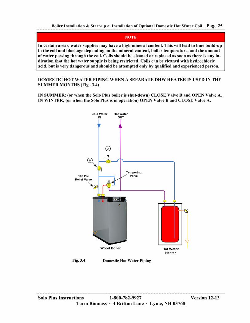
DOMESTIC HOT WATER PIPING WHEN A SEPARATE DHW HEATER IS USED IN THE
SUMMER MONTHS (Fig . 3.4)
IN SUMMER: (or when the Solo Plus boiler is shut-down) CLOSE Valve B and OPEN Valve A.
IN WINTER: (or when the Solo Plus is in operation) OPEN Valve B and CLOSE Valve A.
Boiler Installation & Start-up > Installation of Optional Domestic Hot Water Coil Page 25
NOTE
In certain areas, water supplies may have a high mineral content. This will lead to lime build-up
in the coil and blockage depending on the mineral content, boiler temperature, and the amount
of water passing through the coil. Coils should be cleaned or replaced as soon as there is any in-
dication that the hot water supply is being restricted. Coils can be cleaned with hydrochloric
acid, but is very dangerous and should be attempted only by qualified and experienced person.
Wood Boiler Hot Water
Heater
Cold Water
IN
Hot Water
OUT
B
A
Tempering
Valve100 Psi
Relief Valve
Fig. 3.4 Domestic Hot Water Piping

Solo Plus Instructions 1-800-782-9927 Version 12-13
Tarm Biomass · 4 Britton Lane · Lyme, NH 03768
3.4.8 Installing the 339N Probe Thermometer The 339N Probe Thermometer (Part # 339N) is to be installed just downstream of the boiler’s flue
collar. Drill a ¼‖ hole in the side of the pipe and insert the probe all the way in (see Fig. 3.5). This
thermometer indicates of how well the wood is burning and when to clean the heat exchange tubes. If
burning dry wood that is split, it should achieve temperatures of 500-600 ºF (260-316 ºC) or more on
the probe thermometer.
If operation of the boiler is not achieving temperatures this high, check the following things:
1. Is the by-pass damper latched tightly closed?
2. Are the vanes on the draft fan clean and not filled with ash or dust?
3. Are the primary air channels open (see Section 4.16.5).
4. Is the wood dry (<20%) and split to the proper size?
5. What is the condition of the firebox ceramics?
In most instances, low stack temperatures are an indication that the wood is not dry.
If boiler operations have been producing consistent temperatures and the flue temperature has been
creeping upward, this is an indication that it is time to clean the heat exchange tubes by brushing.
3.4.9 Installing the Optional Turbulators The 3‖ turbulators (part # 092244) are used to increase the heat exchange efficiency of the Solo Plus
boiler connected to a thermal storage tank system.. They are typically not used when a thermal storage
tank is not present.
To install the turbulators, remove the access cover above the heat exchange tubes. After brushing the
tubes place a turbulator in each heat exchange tube.
Boiler Installation & Start-up > Installing the 339N Probe Thermometer Page 26
Fig. 3.5 339N Thermometer
Installed
NOTE
Tarm Biomass recommends that the turbulators not be installed when a boiler is first installed.
Operate the boiler without the turbulators installed until you maintain a consistent flue tem-
perature of 500 ºF (260 ºC). Constant flue temperatures of less than 300 ºF (148 ºC) are too low
when the turbulators are installed.

Solo Plus Instructions 1-800-782-9927 Version 12-13
Tarm Biomass · 4 Britton Lane · Lyme, NH 03768
3.4.10 Control Logic TYPICAL CONTROL LOGIC FOR USE WITH BLADDER LINED COIL-TYPE THERMAL
STORAGE SYSTEMS (Refer to Plumbing Diagram STSS1 or STSS2):
The process begins when a fire is lit in the boiler and the boiler’s control is reset. Water within the
boiler begins to warm. Hot water from the boiler will begin to circulate to the heating system when the
water temperature reaches approximately 165 ºF (74 ºC). Depending on the return water temperature
at the 4440A3 Termovar valve (TV1), water will either circulate back into the return of the boiler or
will continue on to the supply manifold.
TV1 is a three way thermostatic tempering valve. Port 3, which is the return to the boiler, always
stays open. Port 1 remains open until it senses 165 ºF (74 ºC) water. At temperatures above 165 ºF
(74 ºC), Port 1 on TV1 begins to close and Port 2 begins to open. Port 2 is fully open when the return
water reaches 172 ºF (78 ºC).
The thermostatic element in the Termovar prevents cold water returning to the boiler until the boiler
reaches operating temperature. The Termovar then gradually opens, blending hot boiler supply water
with the cold return water. Once system temperature equalizes, the Termovar opens fully to allow full
flow to and from the heating load (the house and/or a heat storage system). Please note: The balancing
valve shown as a 1 ¼‖ ball valve upstream from port 1 is essential. Start with this valve closed ½ way
and adjust more open or closed as necessary. Never fully close or fully open this valve. For custom-
ers who have chosen the LOADING UNIT TERMOVAR 4832S the balancing valve is built in and
balances automatically.
Assuming that TV1 is hot, the water being circulated by C3 is now heading for the supply manifold.
If no zones are calling for heat the Honeywell V8043F1101 zone valve (ZV1) will remain closed. All
of the hot supply water being moved by C3 must travel through the heating coils in the thermal stor-
age system moving from top to bottom and then back through Port 2 of the Termovar and back to the
boiler.
Tarm Biomass recommends the use of the BLTCONTROL (available through Tarm Biomass) where
the Solo Plus boiler is used with another backup boiler. BLTCONTROL is a three position control
that allows switching between wood only, wood with automatic back-up, or back-up only, by control-
ling the operation of the back-up auxiliary boiler. BLTCONTROL takes input from a zone relay con-
trol and determines based on thermal storage system temperature or second stage thermostat reading,
whether to pull heat from the thermal storage system or the back up auxiliary boiler. BLTCON-
TROL simply integrates the Solo Plus boiler and thermal storage system with an existing fossil fuel
heating system.
If at any point while the boiler is in operation, a zone calls for heat, ZV-1 opens and circulator C1 is
energized. Heat flows directly from the boiler to the supply manifold. If the boiler has burned
through its wood and has cooled, Port 2 of the TV1 valve will close and C3 will stop. Flow through
the boiler will cease. Once the boiler is eliminated from the plumbing circuit, any zone that calls must
pull heat through the thermal storage system. Return water passes into the bottom of the heating coils
and exits the top of the coils, re-heated by the thermal storage system, and moves to the supply mani-
fold. If however, upon a call for heat, the temperature in the thermal storage system is below the aq-
uastat (HONEYWELL L4008A or equivalent) set point, C1 will cease operation and ZV-1 will close.
The back up boiler will be energized through the switch control to meet the heat demand.
Boiler Installation & Start-up > Control Logic Page 27

Solo Plus Instructions 1-800-782-9927 Version 12-13
Tarm Biomass · 4 Britton Lane · Lyme, NH 03768
Tarm Biomass recommends the use of an additional Termovar valve model 6440AF (TV2) for most
installations. Without TV2 it is possible that when a small zone is the only zone calling, a master
bathroom zone for instance, all of the heat the boiler is producing is drawn to the small zone. The re-
sult is that a 100,000 – 175,000 Btu (30-50 kW) boiler is sending all of its output to a 2,500 Btu (0.73
kW) load. The boiler could quickly reach operating temperature and shut off, which must be avoided.
TV2 solves this problem. It operates much the same way that TV1 operates except that it is a divert-
ing valve. Port 1 of TV2 receives water from the return manifold. Port 2 of TV2 is connected to the
supply manifold. Port 3 of TV2 is connected to the return to the boiler and to the thermal storage sys-
tem. When the TV2 senses water 165 ºF (74 ºC). and above, it shunts water from Port 1 to Port 2
(back to the supply manifold). Because water returning to the boiler from the return manifold is di-
minished, the remaining flow from the boiler is forced through the heating coils in the thermal storage
system. The result is that both the zone and the thermal storage system receive hot water and the
boiler may continue to burn with a demand equal to or greater than its output. The end result is that
the heating load is always prioritized over the thermal storage system, but heat not used will be stored
in the thermal storage system for later use.
Please note the use of two opposing weighted check valves on the same pipe leading from the top of
the heating coils in the thermal storage system. Their purpose is to act as a thermal trap preventing
heated water from migrating out of the thermal storage system by convection. A ―U‖ shaped pipe trap
usually will not have a useful effect. If check valves are used, we recommend that they be cast iron
bodied universal style flow checks. They must not be swing type check valves, as natural gravity
flow of water will push swing check valves open.
TYPICAL CONTROL LOGIC FOR USE WITH PRESSURE TANK THERMAL STORAGE
SYSTEMS (Refer to Plumbing schematic PT1 or PT2):
The process begins when a fire is lit in the boiler and the boiler’s control is reset. Water within the
boiler begins to warm. Hot water from the boiler will begin to circulate to the heating system when the
water temperature reaches approx. 165 ºF (74 ºC). Depending on the return water temperature at the
440A3 Termovar valve (TV1), water will either circulate back into the return of the boiler or will con-
tinue on to the supply manifold.
TV1 is a three way thermostatic tempering valve. Port 3, which is the return to the boiler, always
stays open. Port 1 remains open until it senses 165 ºF (74 ºC) water. At temperatures above 165 ºF
(74 ºC), Port 1 on TV1 begins to close and Port 2 begins to open. Port 2 is fully open when the return
water reaches 172 ºF (78 ºC).
The thermostatic element in the Termovar prevents cold water returning to the boiler until the boiler
reaches operating temperature. The Termovar then gradually opens, blending hot boiler supply water
with the cold return water. Once system temperature equalizes, the Termovar opens fully to allow full
flow to and from the heating load (the house and/or a heat storage system). Please note: The balancing
valve shown as a 1¼‖ ball valve upstream from port 1 is essential. Start with this valve closed ½ way
and adjust more open or closed as necessary. Never fully close or fully open this valve. For custom-
ers who have chosen the LOADING UNIT TERMOVAR 4832S the balancing valve is built in and
balances automatically.
Boiler Installation & Start-up > Control Logic Page 28

Solo Plus Instructions 1-800-782-9927 Version 12-13
Tarm Biomass · 4 Britton Lane · Lyme, NH 03768
Assuming that TV1 is hot, the water being circulated by C3 is now heading for the supply manifold.
If no zones are calling for heat the C1 pump will be off (If used, ZV-1 will also be closed). All of the
hot supply water being moved by C3 must travel through the thermal tanks from top to bottom and
then back through Port 2 of the Termovar and back to the boiler.
Tarm Biomass recommends the use of the BLTCONTROL (available through Tarm Biomass) where
the Solo Plus boiler is used with another backup boiler. BLTCONTROL is a three position control
that allows switching between wood only, wood with automatic back up, or back up only, by control-
ling the operation of the back up auxiliary boiler. BLTCONTROL takes input from a zone relay con-
trol and determines based on thermal storage system temperature or second stage thermostat reading,
whether to pull heat from the thermal storage system or the back up auxiliary boiler. BLTCON-
TROL simply integrates the Solo Plus boiler and thermal storage system with an existing fossil fuel
heating system.
If at any point while the boiler is in operation, a zone calls for heat circulator C1 is energized (If used,
ZV-1 will open). Heat flows directly from the boiler to the supply manifold. If the boiler has burned
through its wood and has cooled, Port 2 of the TV1 valve will close and C3 will stop. Flow through
the boiler will cease. Once the boiler is eliminated from the plumbing circuit, any zone that calls must
pull heat through the thermal storage system. Return water passes into the bottom of the thermal tanks
and exits the top of the tanks, re-heated by the thermal storage system, and moves to the supply mani-
fold. If however, upon a call for heat, the temperature in the thermal storage system is below the
aquastat (HONEYWELL L4008A or equivalent) set point, C1 will cease operation (If used, ZV-1 will
close). The back up boiler will be energized through the BLTCONTROL to meet the heat demand.
Tarm Biomass recommends the use of an additional Termovar valve model 6440AF (TV2) for most
installations. Without TV2 it is possible that when a small zone is the only zone calling, a master
bathroom zone for instance, all of the heat the boiler is producing is drawn to the small zone. The re-
sult is that a 100,000 – 175,000 Btu (30-50 kW) boiler is sending all of its output to 2,500 Btu (0.73
kW) load. The boiler could quickly reach operating temperature and shut off, which must be avoided.
TV2 solves this problem. It operates much the same way that TV1 operates except that it is a divert-
ing valve. Port 1 of TV2 receives water from the return manifold. Port 2 of TV2 is connected to the
supply manifold. Port 3 of TV2 is connected to the return to the boiler and to the thermal storage sys-
tem. When the TV2 senses water 165 ºF (74 ºC). and above, it shunts water from Port 1 to Port 2
(back to the supply manifold). Because water returning to the boiler from the return manifold is di-
minished, the remaining flow from the boiler is forced through the thermal tanks in the thermal storage
system. The result is that both the zone and the thermal storage system receive hot water and the
boiler may continue to burn with a demand equal to or greater than its output. The end result is that
the heating load is always prioritized over the thermal storage system, but heat not used will be stored
in the thermal storage system for later use.
Boiler Installation & Start-up > Control Logic Page 29

Solo Plus Instructions 1-800-782-9927 Version 12-13
Tarm Biomass · 4 Britton Lane · Lyme, NH 03768
3.4.11 Electrical Connections The control panel on the Solo Plus is supplied as a pre-wired assembly. All that is required on-site is
to connect to 120 Volt service at the junction box that was installed on the back panel of the boiler.
Please refer to electrical drawings in Section 6. 3.4.12 Boiler Control Panel Connections The 3 sensors bulbs from the control panel are pre-installed in well #21. Insure that the sensor bulbs
are pushed all the way to the bottom of the well. The brass diaphragm well for the pressure gauge is
preinstalled in well #23. VERY IMPORTANT! The thin stainless sensor for the Lo-Limit thermostat
is preinstalled in the drywell over the flue collection box. Leave it in this location for operating the
boiler with a thermal storage tank. The Lo-Limit is set to 90 ºC (194 ºF). If the boiler will be operating
without a thermal storage tank, the stainless sensor must be moved to well #24 with the three sensors
from the control panel. The Lo-Limit needs to be set to 60 ºC (140 ºF) when operating without a ther-
mal storage tank (refer to Section 3.3.5 and Section 4.1).
3.4.13 Description of Functions Note in brackets (Section 4.1).
To start the boiler from cold, the reset switch (N) must be pressed, after which a relay closes and re-
mains active. The relay switches the fan and circulator on. When the boiler temperature reaches the
minimum thermostat setting (P). Boiler thermostat (I) regulates the boiler. If the boiler temperature
falls below minimum thermostat setting (P), the fan is switched off.
3.4.14 Operating Thermostat The Operating Thermostat regulates the fan. Moving the knob in the clock-wise direction will raise the
boiler’s set-point (temperature). The recommended operating range for the boiler is 180-185 ºF
(82-85 ºC). The Operating Thermostat’s Hi-Limit is 194 ºF (90 ºC). By using the boiler’s temperature
gauge, adjust the boiler’s set-point by moving the Operating Thermostat. This should be set at initial
start-up. There is a metal spring clip inside the knob to help keep the knob from moving out of adjust-
ment. The boiler can be operated above 180 ºF (82 ºC) if it is used without storage or with a thermal
storage tank that can withstand pro-long temperatures above 180 ºF (82 ºC). Do not operate the
boiler the boiler above 180 ºF (82 ºC) if it is used with a thermal storage tank with an EPDM
rubber liner. (see Section 4.1). The boiler should not be operated below 180 ºF (82 ºC).
3.4.15 Lo-Limit Thermostat There is a Lo-Limit thermostat on the boiler control panel which switches off the fan if the wood has
burned out. When the boiler is operated without a thermal storage tank, set the dial to 60 °C (140 ºF).
The thin sensor must be placed in well #21. When the boiler is operated with a thermal storage tank,
set the dial to 90 ºC (194 ºF). The thin sensor must be placed in the drywell over the flue collec-
tion box. (see Section 4.1).
Boiler Installation & Start-up > Electrical Connections Page 30

Solo Plus Instructions 1-800-782-9927 Version 12-13
Tarm Biomass · 4 Britton Lane · Lyme, NH 03768
3.5 Commissioning the Boiler 3.5.1 Safety Plumbing The boiler pressure relief valve (provided, part # 1040705), must be installed as shown in Fig. 3.5.
This is to ensure that excessive pressure will not be developed in the boiler.
A thermostatic mixing valve (accessory, part # K4440A3 or 4832S), and boiler circulator (included
with the 4823S) should be incorporated into the heating system piping as shown in Fig. 3.6. When the
K4440A3 is used a ball valve (I) (not provided) must be installed upstream of Port 1 of valve TV-1.
The valve should be set at half open (and the handle removed), in order for the tempering loop to func-
tion correctly. If accessory K4440A3 Termovar mixing valve is provided for use as TV-1, the unions
supplied with the valve have internal valves which must be fully open.
Boiler Installation & Start-up > Commissioning the Boiler Page 31
Installed Relief Valve Fig. 3.6
1
2
Wood Boiler
1¼"
1¼"
Automag
Zone ValveBioHeat Part # AUTOMAG
C-3
1"
1"
1¼"
3
BioHeat Part
# L4006B
A
B
TV-1BioHeat Part #
K4440A-3
I
D
K
C-3
Termovar
Option A
Termovar
Option B
TV-1BioHeat Part #
4832S
23
1
Fig. 3.7 Typical Plumbing Schematic
Solo Plus Instructions 1-800-782-9927 Version 12-13
Tarm Biomass · 4 Britton Lane · Lyme, NH 03768
3.5.2 Filling and Venting The best connection for filling the boiler with water is at the boiler drain. During filling the circulation
pump is switched off. Filling takes place through a hose which is screwed onto the boiler drain and
connected to a water supply faucet. Fill the hose prior to filling the boiler, otherwise air in the hose
will be pushed into the boiler system. Remove the hose after filling up. High quality air elimination
equipment is recommended in the heating system installation.
3.5.3 Final Installation Checklist This final installation checklist should be reviewed before starting up the boiler for the first time:
General Boiler Installation ○ Boiler set and level.
○ Clearances to Combustibles maintained.
○ Combustion make-up air provided.
Chimney ○ Appropriate chimney connector installed.
○ Chimney and termination meet requirements.
○ Proper chimney draft.
Plumbing ○ Plumbing fittings tight.
○ Termovar mixing valve or loading unit installed and orientated correctly.
○ Pressure relief valve installed and tested.
Electrical ○ Boiler connected to dedicated 120V, 60 hertz 15 amp power supply.
○ Functional testing performed satisfactory. ○ Dump zone connected.
Boiler Installation & Start-up > Filling and Venting Page 32
NOTE
The heating system main supply and return piping will need to be at least 1.25” (32 mm) for
correct boiler heat output distribution. All field-run piping should be back-flushed to clean and
remove debris. Adequate filling and venting ports should be added so that air can be removed
from the system. The system should be pressure tested before being placed into service.
NOTE
If water quality is poor or PH unsatisfactory, the installer should consider water treatment ad-
ditives during filling and water testing as part of annual maintenance.

Solo Plus Instructions 1-800-782-9927 Version 12-13
Tarm Biomass · 4 Britton Lane · Lyme, NH 03768
3.5.4 Combustion and Performance Testing The boiler should be fired to test for performance, using Section 4.0 as a guideline.
Provision should be made for dissipating the heat generated.
Have enough fuel to complete an entire testing program.
Verify control strategy
Check that the boiler thermostat is functioning. Check the overheat thermostat, a temporary connec-
tion is made between terminals 5 and 6 on terminal strip Xl (see circuit diagrams Section 6). The fan
must switch off when the boiler reaches the temperature at which the overheating thermostat is trig-
gered. (The temporary connection between terminals 5 and 6 must be removed when the overheating
thermostat has been checked). The overheat thermostat can be switched on again when the tempera-
ture has fallen by about 60 ºF (15 °C) after 10-15 minutes. The unlocking knob (H) (see Fig. 4.1) is
located under a protective cap.
Boiler Installation & Start-up > Combustion and Performance Testing Page 33

Solo Plus Instructions 1-800-782-9927 Version 12-13
Tarm Biomass · 4 Britton Lane · Lyme, NH 03768
4.0 Boiler Operation, Maintenance, and Service Maintenance
It is also the responsibility of the user that the boiler be cleaned and maintained according to:
Normal practice.
The instructions of this manual.
Instructions for the controls or equipment from other manufacturers.
Other circumstances described in the written warranty.
4.1 Control Panel Orientation Letters in brackets () in this section refer to the button with the corresponding letter on the control
panel. All temperature values are in degrees Centigrade.
Boiler Operation, Maintenance, and Service > Control Panel Orientation Page 34
The Temperature Gauge shows the boiler’s temperature. The
boiler temperature is adjusted via the Operating Thermostat (I).
Fig 4.1
C
E
D
F
B
H
N
P
I
(B) Pressure Gauge
The Pressure Gauge shows the boiler’s pressure.
(C) Temperature Gauge
Psi ºF
ºF
Psi

Solo Plus Instructions 1-800-782-9927 Version 12-13
Tarm Biomass · 4 Britton Lane · Lyme, NH 03768
This switch is not used in the North American Market.
During operation the fan switch is always on.
The Fuse is located behind screw cap.
The overheat thermostat switches off the fan when the boiler
temperature is approximately 100 °C (212 ºF). wait until the
boiler temperature has fallen to 75 °C (165 ºF). To switch on
again, unscrew the protective cap and push in the ejected pin.
Operating thermostat 0-90 °C (0-195 ºF). The recommended set-
point temperature is 82-85 °C ( 180-185 ºF).
Boiler Operation, Maintenance, and Service > Control Panel Orientation Page 35
(E) Switch for Circulator Pump
(F) Fan Switch
(H) Overheat Thermostat
(I) Operating Thermostat
(D) Fuse max. 6.3A (5X20 mm).

Solo Plus Instructions 1-800-782-9927 Version 12-13
Tarm Biomass · 4 Britton Lane · Lyme, NH 03768
4.2 Items to Check Before Using 1. Check the heating system water pressure before using the system. NOTE: Water may not be
added to the boiler while it is running.
2. Ensure that the chimney connector pipe is connected to the chimney and that the chimney is
free of obstructions
3. Ensure that all circulators are connected and operational.
4. Turn on the main electrical service switch.
5. Open any valves that may have been closed temporarily during set-up.
6. The transport protectors for the ceramic bricks are made of wood and will quickly burn. Do
not try to remove them.
7. Check the Operating Thermostat for proper setting. The stop on the underside of the knob
should be on the left hand side of the stop screw. The knob should be resting against stop
screw.
8. Confirm that the setting on the Honeywell L4008B (overheat aquastat) is set to 200 °F
(94 °C).
9. Confirm correct operation of the bypass damper (Removal of top cover and cleanout
cover is necessary).
Boiler Operation, Maintenance, and Service > Control Panel Orientation Page 36
The fan switches off automatically if the boiler has burned out
and the boiler/flue gas temperature falls.
In units with a thermal storage tank, the fan switches off when
the temperature at the sensor in the flue gas has reached 90 °C
(194 ºF).
If the temperature at the sensor falls below 90 °C (194 ºF) the
reset switch (N) must be pressed to restart combustion in the
boiler.
The Lo-Limit Thermostat switches off the fan when the wood
has burned out. It is set to 60 °C (140 ºF) if there is no thermal
storage tank and 90 ºC (194 ºF) if there is a thermal storage tank.
(N) Reset Switch
(P) Lo-Limit Thermostat
NOTE
Please be advised that simply lifting the bypass rod and pushing it inward will not completely
close and lock the bypass damper. You may hear the clang sound of the bypass damper hitting
the bypass door opening, but that does not guarantee the bypass door is closed fully and locked.
You must, after lifting and pushing forward on the bypass rod, lift the rod again and push in-
ward against the tension of the spring and downward on the rod, locking the bypass mecha-
nism. Hard inward pressure against the spring tension may be required. If you do not feel as
though you are compressing a spring, you have not lifted the bypass rod before pressing inward
a second time. The bypass damper must be fully locked closed during normal operation.

Solo Plus Instructions 1-800-782-9927 Version 12-13
Tarm Biomass · 4 Britton Lane · Lyme, NH 03768
4.3 Starting the Boiler
1. Set the by-pass damper lever in the open position by lifting up and pulling the lever fully for-
ward.
2. Turn ―ON‖ the electrical power service switch mounted on the boiler (if installed).
3. Switch ―ON‖ the draft fan with switch (F) on the control panel (The fan will not start at this
time).
4. Open the loading door and line the bottom of the firebox with several pieces of crumpled
newspaper. Place several pieces of kindling and small pieces of dry wood on top of paper.
5. Place 6 or 8 more crumpled sheets of paper on top of kindling. Light the paper and close the
load door.
6. Immediately, push the reset switch (N) on the control panel. The draft fan will then start.
7. Partially close the by-pass damper leaving it slightly open and unlatched.
8. After about 5 to 6 minutes, open the by-pass fully and turn ―OFF‖ the draft fan switch (F).
Immediately open the upper door slowly and carefully to see that the fire is established. If it is,
add several more small pieces of dry firewood. Close the upper door.
9. Immediately turn ―ON‖ the switch (F) to start the draft fan. Close and latch the by-pass
damper by pushing in and down firmly so that the spring will keep it closed.
10. Wait approximately 5 more minutes, and then look through the sight glass in the ash door. A
full active flame should be seen filling the combustion tunnel. If not, give the fire a few more
minutes before loading with larger fuel. When loading wood, place it close together and uni-
formly front to back and not crosswise.
11. First fire should be low and slow.
With experience, users may well develop their own techniques for lighting and loading the boiler that
may be quicker and easier than described above.
Boiler Operation, Maintenance, and Service > Starting the Boiler Page 37
NOTE
It can take up to ten complete burn-cycles for the combustion stones to “break-in”. Do not ex-
pect a perfect fire the first time.
WARNING
If there is a fire in the firebox, do not leave the boiler with the main power switch “OFF”
This must be left “ON” so the overheat circuit can function, if necessary.
CAUTION CAUTION
☼ The Load and Ash doors must remain closed except when loading fuel or removing ash.
Door gasket seals are very important to the operation of your boiler. They must be main-
tained in good condition and replaced if necessary in order to maintain an air tight seal.
NOTE
If wood is stored in the boiler room, ensure that it is not stored within the clearances to
combustibles or in a way that will impede daily firing or maintenance.
NOTE
The wooden shipping shims holding the refractory in place will burn up. Do not try to remove them!

Solo Plus Instructions 1-800-782-9927 Version 12-13
Tarm Biomass · 4 Britton Lane · Lyme, NH 03768
4.4 Adding Wood
4.4.1 Adding Wood When the Draft Fan is OFF (Boiler at Operating Temperature) 1. OPEN THE BY-PASS DAMPER.
2. TURN UP THE OPERATING THERMOSTAT (I) on the control panel fully clockwise.
This will activate the draft fan, to help prevent the risk of a gas explosion when the door is
opened. Let the fan run for 2-3 minutes to vent the hot gasses before the door is opened.
3. Turn the draft fan off by switching the fan switch (F) to ―OFF‖ on the control panel.
4. Without delay, open the load door ¾‖ with your left hand.
5. Wait approximately 20 seconds.
6. Open the load door slowly, fully, and cautiously!
7. Load the firebox if the previous load of wood has burned down to coals, placing the wood uni-
formly front to back and tight together, not crosswise. If the wood has not burned to low coals,
do not load more wood.
8. Close the loading door.
9. Turn the draft fan back on by switching the fan switch (F) to ―ON‖ on the control panel.
10. Close and lock the by-pass damper by pushing in and down firmly so that the spring will keep
it closed.
4.4.2 Adding Wood When the Draft Fan is OFF (Boiler Temperature below 140ºF (60ºC))
1. OPEN THE BY-PASS DAMPER.
2. Push the reset switch (N) on the control panel to activate the fan. Let the fan run for 2-3 min-
utes to vent any hot gases.
3. Turn the draft fan off by switching the fan switch (F) to ―OFF‖ on the control panel.
4. Without delay, slowly and cautiously open the loading door ¾‖ with your left hand and wait
approximately 20 seconds.
5. If there is sufficient live coals left in the firebox to re-ignite the next load of wood, there will
not be the need to use paper to restart the fire. Place several pieces of dry kindling in the cen-
ter of the firebox over the slot in the refractory and rake the live coals from the sides of the
firebox to the center on top of the kindling.
6. Add enough firewood to carry the estimated heat load for the next 8 hours, as per the ―Daily
Firing‖ on page 39, which are very important.
9. Close the load door and immediately turn ―ON‖ the fan switch (F). Close and lock the by-pass
damper by pushing in and down firmly so that the spring will keep it closed.
10. HOWEVER, if you find very few live coals left in firebox after opening the load door in step
#3 above, follow steps 3-#10 in Section 4.3 to restart the fire.
4.4.3 Adding Wood When the Draft Fan is ON
1. OPEN THE BY-PASS DAMPER.
2. WAIT, 2-3 minutes with the draft fan running.
3. Turn off the draft fan by using the fan switch (F) on the control panel.
4. Without delay, open the loading door ¾‖ with your left hand.
5. Wait approximately 20 seconds.
6. Open the load door slowly, fully, and cautiously!
7. Load the firebox with wood, placing the wood uniformly front to back and tight together, not
crosswise.
8. Close the load door.
9. Immediately turn the draft fan back ―ON‖ by fan switch (F) on the control panel.
10. Close and lock the by-pass damper by pushing in and down firmly so that the spring will keep
it closed.
Boiler Operation, Maintenance, and Service > Adding Wood Page 38

Solo Plus Instructions 1-800-782-9927 Version 12-13
Tarm Biomass · 4 Britton Lane · Lyme, NH 03768
CAUTION CAUTION
☼ RISK OF WOOD GAS EXPLOSION as explosive gases may be present. When burning a
Solo Plus boiler, the operating thermostat turns off the draft fan when the boiler gets up to
temperature. This cuts the supply of oxygen to the fire and the flame goes out. This re-
mains, however lots of hot coals and a red hot refractory which will continue to bake the
wood creating a build up of hot gas in the firebox. Any person dealing with a Solo Plus
boiler needs to keep in mind that hot explosive gases may be present. These gasses are hot
enough to burn, but without a source of oxygen they can’t burn. After the draft fan has
been off for 15-20 minutes when the gases are hot and explosive, opening the door may pro-
vide enough oxygen for a sudden back flash or puff (wood gas explosion) to occur. This is
the reason behind the safety precaution of NEVER OPENING THE LOAD DOOR
UNLESS THE FAN HAS BEEN RUNNING IN THE LAST FEW MINUTES to vent hot
explosive gasses from the firebox first.
4.5 Daily Firing The following firing procedures should be followed, especially when the boiler has excess capacity (as
it will have during milder weather).
1. Load the boiler with wood at least 3 times a day.
2. Only load the boiler with the amount of wood needed for approximately 8 hours of burn-
ing to cover the heating load caused by the weather and the heat loss of the house. The
wood should be totally burned and reduced to low coals so that the slot in the refractory is ex-
posed before reloading the firebox with wood. The ability to judge the correct amount of
wood for each installation is somewhat unique. Your goal should be to keep the firebox as dry
as possible by not overloading the boiler with wood in periods of lower heat demand.
3. If steps 1 & 2 above are followed, the heating surfaces of the wood firebox will have a chance
to dry out as it will burn down to charcoal at the end of each load of wood.
4. If steps 1 & 2 above are followed there will be no problems with smoke spilling out of the
load door because only coals will be present when reloading. The next batch of wood will ig-
nite easily and quickly because of the presence of the coals remaining from the previous load.
5. If steps 1 & 2 above are followed, the by-pass damper will open easily and won’t be stuck
shut with creosote.
6. Maintain a high boiler temperature of at least 180-190 ºF (82-88 ºC).
7. Clean the boiler frequently as per the instructions elsewhere in this manual (see section 5).
Routine cleaning will help maintain boiler efficiency. Accumulated ash and soot act as an in-
sulator and reduce boiler combustion and heat exchange efficiency.
8. Due to greatly reduced heat demand, it is not wise to fire the wood in the summer. Smoke and
odors are more noticeable during the warmer months. Therefore, we do not recommend burn-
ing wood in the summertime. Save your wood fuel for colder weather, or equip your boiler
with a thermal storage tank system. Contact Tarm Biomass or your local dealer for more in-
formation.
The refractory tunnel must be kept free of ashes and charcoal so that there enough room for the gasifi-
cation flame. Use the ash rake to pull the ashes and coals out of the tunnel. Leave the coals on the
boiler floor and they will burn up with the next fire.
Boiler Operation, Maintenance, and Service > Daily Firing Page 39

Solo Plus Instructions 1-800-782-9927 Version 12-13
Tarm Biomass · 4 Britton Lane · Lyme, NH 03768
Keep in mind that the refractory bricks are hardest when they are new. The refractory bricks will sof-
ten with age. When loading wood into the boiler and using tools around the refractory areas keep this
in mind.
Do not break the refractory by:
1. Throwing wood directly onto the refractory (place the first few pieces into the boiler gently).
2. Digging or prying at the refractory in the areas of the slot or the tunnel.
4.6 Shutting Down the Boiler Switch off the boiler by turning off the fan switch on the control panel. The circulating pump will
shut off when the boiler is cool. Take care not to shut off power to the boiler circulator if there is any
chance that the boiler may heat up again.
4.7 Operation with Thermal Storage System
Tarm Biomass recommends the use of a Thermal Storage Tank System with the Solo Plus boiler. The
boiler will always be able to discharge its heat resulting in better combustion, less depositing of soot
and tar, and longer boiler life. Operation is simplified as the filling chamber can be completely filled.
The boiler can be fired when you have time and the house can be supplied with heat as required from
the thermal storage system. An added benefit is that domestic hot water can also be created in the res-
ervoir. Keep in mind that the amount of wood placed in the boiler’s filling chamber depends on the
size and the temperature of the thermal storage reservoir. The boiler should not be fired beyond the
reservoir’s heat storage capacity. Do not add wood until the temperature in the thermal storage system
has fallen to 140-160 °F (60-72 ºC), so that the reservoir will again be able to absorb heat. Set the
boiler temperature to a maximum temperature of 180 °F (82 ºC).
4.8 Creosote Tar deposits are not normally a problem in a Solo Plus boiler when it is fired as directed. Your firebox
will form creosote on the walls. During combustion, when the draft fan is running, gasses and smoke
are created which make up the main part of the wood’s heat value. Formic and acetic acids and other
gasses are mixed with the right quantity of combustion air at very high temperatures producing boiler
efficiency of around 80%. This highly efficient combustion process produces virtually no smoke or
creosote.
If soft or tar like creosote is found in the firebox it can be a symptom that the boiler is being filled with
more wood than is necessary. Glazed, crunchy and scaly creosote in the main firebox is common and
expected. Glazed, crunchy, or scaly creosote should never be found in the lower combustion chamber,
heat exchange tubes, or in the chimney. When wood is burned slowly, it produces tar and organic va-
pors, which combine with expelled moisture to form creosote. The creosote vapors condense in the
relatively cool chimney flue of a slow-burning fire. As a result, creosote residue accumulates on the
flue lining. When ignited this creosote makes an extremely hot fire. The chimney and chimney con-
nector should be inspected daily for creosote buildup until experience shows how often cleaning is
necessary. If creosote has accumulated it should be removed to reduce the risk of a chimney fire.
Boiler Operation, Maintenance, and Service > Daily Firing Page 40
WARNING
It is important to keep the load and ash doors closed during operation and to maintain the
door seals in good condition.

Solo Plus Instructions 1-800-782-9927 Version 12-13
Tarm Biomass · 4 Britton Lane · Lyme, NH 03768
4.9 Combustion Process Solo Plus boilers have excellent combustion efficiency.
When the boiler gets up to temperature, the draft fan shuts down and stops the supply of combustion
air to the firebox. The fire shuts down due to the lack of oxygen and does not continue smoldering to
cause smoke, creosote or overheating. When the boiler temperature drops, the fan will turn on re-
igniting the coals which have been resting on the refractory. During the off cycle, the coals stay hot
enough to burn but they will be dormant because of the lack of oxygen. The combustion process of
the Solo Plus allows to burn wood as efficiently, as clean and as controlled as many fossil fuel heating
systems.
4.10 Heat Output The Solo Plus boiler is designed to operate in an output range from as low as 17,000 BTU’s (5 kW’s)
per hour. At maximum output, the fan will operate continuously. At lower outputs, the fan and the
fire will cycle on and off just as an oil or gas burner does to meet the heating demand. However, try-
ing to operate the Solo Plus boilers during periods of lower heat demand can be problematic due to
lower chimney draft.
4.11 Burn Time Burn time is dependent of the type of fuel, the heat load on the boiler as well as how full the firebox is
loaded. However, the recommended maximum burn time is approximately 8 hours. Remember to
only load the boiler with the amount of fuel that will be fully consumed in approximately 8 hours.
Boiler Operation, Maintenance, and Service > Combustion Process Page 41
NOTE
The chimney draft must always be strong enough to prevent reversed flow in the boiler’s pri-
mary and secondary air supply ducts. Otherwise, smoke may be forced backwards through the
boiler and emitted out of the fan when it is off. This reversed flow will maintain a smoldering
fire in the boiler and can lead to partial or complete blockage of the air supply ducts, causing
inefficient and problematic operation. It may also result on an objectionable smell of creosote or
smoke in your home. These problems are eliminated entirely when operating the boiler with
higher demand on it, such as a thermal storage tank system, and have a chimney which main-
tains proper draft.

Solo Plus Instructions 1-800-782-9927 Version 12-13
Tarm Biomass · 4 Britton Lane · Lyme, NH 03768
4.12 Primary Air Adjustment The primary air should be set to open fully when the draft fan is running. The stop (B) should not
touch the adjustment bolt (A) when the damper is the open position. However, if are regularly seeing
temperatures at the flue collar of the boiler of over 600 °F (315 °C) when the boiler is clean, we sug-
gest decreasing the primary air to lower the flue temperature. Adjust the stop in front of the draft fan
under the top front jacket panel. Loosen the locking nut and turn the bolt (A) in for less primary air
lowering the flue temperature to approximately 600 °F (315 °C). Tighten the locking nut when ad-
justed properly.
4.13 Secondary Air Adjustment The primary air coming through the holes behind the loading door (C) and the total quantity of air nor-
mally should not have to be changed if the boiler is kept clean.
Correct secondary air adjustment is essential for optimum combustion and efficiency. Adjustment is
by means of the bakelite knob on the front of the boiler next to the top left corner of the ash door (see
diagram at top of page 40). To adjust, pull the knob down and slide left (more air) or right (less air).
The drier the wood is, the more secondary air required.
After approximately 45 minutes of operation with a load of wood, the boiler and refractory should be
heated. Observe the flame through the observation port or open the lower door carefully while the
fan is still running. Adjust the secondary air as needed. Once the proper adjustment has been set, it
should only be necessary to re-adjust when changing the type or quality of fuel. Use diagrams in Fig.
4.5 as a guide to help in setting the secondary air.
The basic rules for setting the secondary air are as follows: If the wood is dry, add more secondary air.
If the wood is greener, use less secondary air. To have the knob in the center, usually covers most
situations.
Boiler Operation, Maintenance, and Service > Primary Air Adjustment Page 42
A
B
Fig 4.2 Primary Air Adjustment
C
Fig 4.3 Primary Air Ducts (Holes)
Fig 4.4 Secondary Air Adjustment

Solo Plus Instructions 1-800-782-9927 Version 12-13
Tarm Biomass · 4 Britton Lane · Lyme, NH 03768
4.14 Firing Tips It is important to use wood of an appropriate size (length and diameter) and to stack it properly so that
there are no ―holes‖ and ―hanging pieces‖ in the wood stack, which must then be regularly stirred with
the poker to form it into a compact mass. The diameter of the wood ideally should not exceed 4-6
inches (100-120 mm) as ―holes‖ would then form more easily in the wood layer, creating a risk of re-
duced heating output. Thick pieces of wood ideally should be split to a diameter of 4-6 inches (100-
120 mm).
See Figure 4.5 for correct flame length.
4.15 Operation During Summer
Solo Plus boilers will operate at highest efficiency burning wood during the cooler months, but, be-
cause of the characteristics of the gasification combustion system, it is possible to operate the boiler
through the fall and spring whenever the outside night temperatures require central heating. Proper
chimney draft and gasket seals are more critical to operation during the times of low heat demand. If
the chimney draft is too high or air leaks around the fan or doors, the boiler may tend to overheat. If
the chimney draft is too low, the fire will tend to either go out or smoke back-up through the fan and
into the building. The key to operating the boiler in the warmer months and even in the summer is to
install a Thermal Storage Tank System. Contact Tarm Biomass or your local dealer for more informa-
tion on Thermal Storage Tank Systems.
Boiler Operation, Maintenance, and Service > Firing Tips Page 43
Fig. 4.5
Too Much Air
The flame is blue and too
short. Adjust knob to the
right
Too little Air
Flame too long and reddish yellow
Adjust knob to the left.
Correct setting
The flame is yellow and
pale bluish.
WARNING
We recommend not firing the Solo Plus boiler in the summer or other times of low heat
demand unless used with a Thermal Storage System.
Operation at lower output will cause greater creosote formation in the firebox. This
creosote, if excessive, can lead to shortened boiler life.

Solo Plus Instructions 1-800-782-9927 Version 12-13
Tarm Biomass · 4 Britton Lane · Lyme, NH 03768
4.16 Cleaning and Maintenance
4.15.1 Ash Removal The boiler must be cleaned regularly. Lack of cleaning can result in loss of boiler efficiency, malfunc-
tioning and reduced boiler life.
Most ash produced during boiler operation will be drawn down into the gasification chamber where it
can be removed. Ash should be cleaned out of the gasification chamber, from both the combustion
tunnel and the refractory floor, through the ash door as needed, typically every 3-5 days.
Clean the firebox once or twice a month. Ash remaining in the firebox can be worked from the sides
of the firebox to the slot at the center of the refractory where it can fall down to the lower gasification
chamber with the tool provided - use care not to damage the refractory slot. Do not allow a deep build
up (more than 2‖ (50 mm)) of ash on the surface of the refractory.
For ash removal, open the insulating door and the ash door, place your ash pan on the floor in front of
the ash door and pull the ash in this area into the pan using the ash removal tool. Be sure to remove
by the boiler will depend on the type of fuel used.
Boiler Operation, Maintenance, and Service > Cleaning and Maintenance Page 44
WARNING
Before performing any cleaning or maintenance on the boiler, allow boiler to completely
burn through all fuel and to normally cool down and shut off.
NOTE
Turn off power to the boiler before performing any cleaning or maintenance.
WARNING
Ashes removed from the boiler should be placed in a metal container with a tightly fitting
lid The closed container of ashes should be placed on a non-combustible floor or on the
ground, well away from all combustible materials, pending final disposal. If the ashes are
disposed of by burial in soil or otherwise locally dispersed, they should be retained in the
closed container until all cinders have thoroughly cooled. Other waste should not be placed
in this container.

Solo Plus Instructions 1-800-782-9927 Version 12-13
Tarm Biomass · 4 Britton Lane · Lyme, NH 03768
4.16.2 Smoke Box and Heat Exchange Tube Cleaning The smoke box, the flue outlet and the heat exchange tube areas should be cleaned twice a month with
the boiler brush. Let the boiler cool and shut off the power to the boiler. First, remove the top cover.
Next, remove the four wing nuts to the clean-out cover and remove. If you have turbulators, remove
from the heat exchange tubes. Insert the brush into each heat exchanger pipe and work back and forth
thoroughly. Push the brush all the way through, but be careful not to damage the bottom plate under-
neath. Remove fly-ash from the smoke box area above the heat exchange tubes. Ash that falls down
to the bottom of the heat exchanger tubes during cleaning can be removed though the ash door as de-
scribed above. When finished, replace the clean-out cover and the top cover.
4.16.3 Cleaning the Draft Fan The draft fan (Fig. 4.7) must be inspected yearly and cleaned as necessary. Dust and ash buildup on
the fan blades can significantly reduce fan performance.
Remove the screen by removing the four screws (Fig. 4.7). Clean the blades with a soft bristle brush
(paint brush) and a vacuum cleaner. If there is creosote on the fan you may have a chimney draft prob-
lem that needs to be fixed.
Boiler Operation, Maintenance, and Service > Smoke Box and Heat Exchange Tube Cleaning Page 45
Fig. 4.6 Smoke Box and Heat Exchangers
Heat Exchangers
Lo-Limit Sensor Well
By-Pass Damper
NOTE
Clean heat exchanger tubes and smoke box mean better heat transfer from the flue gas to the
water and thus better operating economy.
NOTE
Elevated flue gas temperatures above 600 ºF (315 ºC) may indicate the need to brush the heat
exchange tubes.
Fig. 4.7 Draft Fan

Solo Plus Instructions 1-800-782-9927 Version 12-13
Tarm Biomass · 4 Britton Lane · Lyme, NH 03768
4.16.4 Maintaining Door Seals It is very important to maintain tight seals on the doors. Check the loading door and ash door gaskets
regularly to insure that they are sealing well and that there is no unwanted air leakage into the boiler.
Poor seals can result in air leakage into the boiler and lead to inefficient burning of the boiler or the
escape of smoke and gasses from the boiler. The rope seal used to on doors should be inspected regu-
larly.
Check the seal for alignment on the door frame by examining the imprint made by the frame on the
seal.
Steps to Replace the Door Seals:
1. Remove the two hinge bolts and take off the door.
2. Remove the old sealing with a screwdriver or a chisel.
3. Clean the sealing groove.
4. Press new sealing into the groove. When half the sealing has been inserted, adjust the end and
press in the rest.
5. Secure the sealing by gently tapping with a hammer.
6. Replace the door.
7. Close the door and check its seal.
4.16.5 Cleaning the Primary Air Duct and Channels The primary air channels (on both sides of the load door) can occasionally become blocked reducing
the primary air flow to the firebox.
Checking the Primary Air Openings:
1. Open the outer door and load door.
2. Check the Primary Air duct holes (Fig.4.8 & 4.9) for unobstructed airflow.
3. If necessary, clean the openings and air channels.
Boiler Operation, Maintenance, and Service > Maintaining Door Seals Page 46
NOTE
Please inspect the draft fan carefully – even a thin coating of ash significantly reduces the air
flow and must be removed.
Fig. 4.8 Fig. 4.9 Primary Air Ducts Primary Air Hole

Solo Plus Instructions 1-800-782-9927 Version 12-13
Tarm Biomass · 4 Britton Lane · Lyme, NH 03768
How to Clean the Primary Air Channels (some clear 100% silicone will be needed):
1. Remove the cover to the air distribution box which is located between the loading and ash
doors (Fig.4.10). This is performed by removing the 4 corner nuts and carefully breaking the
silicone seal on bottom of diffuser.
2. The air channels (Fig. 4.11) can then be cleaned with a brush or piece of wire.
3. After cleaning the channels the cover can be reinstalled. Remove the old silicone around the
perimeter of the cover on the back side.
4. Place a new bead of silicone around the perimeter of the cover.
5. Screw cover back into place.
4.16.6 Smoke Pipe Inspection and Cleaning The chimney and the chimney connector must be inspected and cleaned annually. Annually disassem-
ble the stove pipe and clean ash accumulation and inspect for corrosion. If any pipe is substantially
corroded, this section must be replaced. Cleaning the connecting pipe between the boiler and the
chimney is very important for horizontal smoke pipes!
Boiler Operation, Maintenance, and Service > Cleaning the Primary Air Ducts and Channels Page 47
WARNING
Solid-fuel burning appliances need to be cleaned frequently because soot, creosote and
ash may accumulate.
Remove
Fig. 4.10 Air Distribution Cover Cover Removed Fig. 4.11
Primary Air Channels
NOTE
Chimney inspection and maintenance is a critical part of any wood-burning maintenance sched-
ule. Make sure that the chimney connection is secure and airtight. Inspect chimney regularly
and clean as needed.

Solo Plus Instructions 1-800-782-9927 Version 12-13
Tarm Biomass · 4 Britton Lane · Lyme, NH 03768
4.16.7 Chimney Fires Chimney fires are caused when excessive buildup of creosote in the chimney connector pipe or the
chimney is ignited by a racing fire, or when a burning piece of material is swept out of the firebox into
the chimney. If you have a chimney fire, you will hear a roaring sound in your chimney, almost like a
jet airplane. In addition, sparks may be seen flying from the chimney outside the house. Chimney fires
can set fire to the interior of your house or your roof. They are potentially very dangerous, and the fol-
lowing procedure should be followed if you think you have a chimney fire:
1. Call the fire department.
2. Shut all doors and close all air inlets on your boiler.
3. Evacuate your house.
4. If possible, wet your entire roof with a garden hose.
Chimney fires can be avoided by following the recommendations in this manual for minimizing ash
formation, by maintaining your chimney in good condition, and by cleaning your chimney regularly.
A chimney fire should never happen with a Solo Plus boiler!
4.16.8 Checking the Barometric Damper Annually check the barometric damper flap for ease of operation. The barometric damper flap should
operate freely and maintain a chimney draft between -0.025 to -0.05 inches water column.
4.16.9 Cleaning the Jacket Soot on the jacket and the doors can be removed with a cleaner containing ammonium chloride and
acetic acid. Clean the jacket regularly as required to preserve the boiler’s appearance.
4.16.10 Check for Creosote Build-Up Check for creosote buildup in the heat exchange tubes, the smoke pipe and the chimney twice a
month. If during cleaning and maintenance a buildup of creosote is noted anywhere besides the fire-
box, something is wrong with the boiler operation. Check the seal of the door gaskets, the load door
to the smoke duct and the smoke box cover.
4.16.11 Seasonal Shutdown Procedure If the boiler is not being used during the summer season, it is important that the boiler be properly
cleaned. The upper and lower combustion chambers, heat exchanger tubes and upper smoke baffle
should all be cleaned. After the boiler is cleaned, keep all doors and air dampers closed. Remove the
flue pipe and stuff insulation into the flue collar. If you notice condensation forming on the inside of
boiler, hang a 15-25 watt light bulb inside boiler.
4.16.12 Checking the Pressure Relief Valve The pressure relief valve protects the system from dangerously high pressure by opening at a preset
pressure rating to allow fluid to be safely released. The pressure relief valve should be seated properly
and not drip system water. The pressure relief valve should be inspected and maintained according to
the manufactures recommendations.
Boiler Operation, Maintenance, and Service > Chimney Fires Page 48

Solo Plus Instructions 1-800-782-9927 Version 12-13
Tarm Biomass · 4 Britton Lane · Lyme, NH 03768
4.16.13 Checking System Pressure The system expansion tank in a closed system allows for the thermal expansion of the fluid in the
heating system. See the expansion tank’s operating instructions for maintenance requirements.
4.16.14 Heat Storage System Maintenance Please follow the recommended maintenance schedule for these parts of the heating system. Specific
maintenance items for the heat buffer will be specified by the system manufacturer, but items may
include checking any safety valves, anode in any connected hot water reservoir, or system water level
and system PH in static water storage systems.
4.17 Power Outages The boiler will not operate in the event of a power failure. Do not open the loading or ash doors until
power is reestablished. The fan needs to be able to operate to remove combustible gasses.
Boiler Operation, Maintenance, and Service > Checking System Pressure Page 49

Solo Plus Instructions 1-800-782-9927 Version 12-13
Tarm Biomass · 4 Britton Lane · Lyme, NH 03768
5.0 Troubleshooting 5.1 Troubleshooting Guide
Troubleshooting > Troubleshooting Guide Page 50
Symptom Possible Cause Remedy
No Heat in House
Boiler Temperature is Below 150 ºF
(65 ºC) While Burning Wood.
No Fuel in Boiler.
Low Fan Output.
Restart or re-light fire.
Fan wheel Dirty-CLEAN.
Air Ducts Plugged-CLEAN.
Fan Does not Operate. Check Power and Control Panel
Components with Multi-Meter.
By-Pass Damper Open, not Sealing. Close By-Pass Damper-CLEAN.
Combustion Chamber is Ob-
structed.
Clear Ash and Other Obstructions through
lower Door.
Boiler is Dirty Clean Ash off Refractory.
Clear Ash from floor of Boiler.
Brush Heat Exchange Tubes.
Wood is Un-split or Unseasoned. Split Wood and Season to 20% moisture or
less.
Fan Operates Slowly. Bad Motor Capacitor-REPLACE.
Boiler Temperature is Below 140 ºF
(60 ºC), Fan does not Shut Off.
Wrong Setting on Lo-Limit
Thermostat.
Set Lo-Limit Thermostat at 60 ºC
(140 ºF) without storage and 90 ºC
(194 ºF) with storage.
Boiler Didn’t Reach Operating
Temperature on Cold Start-up.
Be sure to Fire Boiler so it heats to above
175 ºF (79 ºC) after a cold start.
Boiler Temperature above 150 ºF (65ºC). Air in Piping. Call Serviceman.
Circulator not Operating. Call Serviceman.
Not Enough Radiation in House. Add Radiation as Needed.
Boiler Functions Well with Good Burn
Times but Inadequate on Coldest Days.
Boiler temperature is Set Too Low. Increase Boiler Water Temperature by Ad-
justing the Operating Thermostat to 190 ºF
(88 ºC).
Excessive Heat Dumped into
Overheat Zone.
Overheat Control Set to Low. Increase Setting on L4008B to 210 ºF (98 ºC).
Short Burn Times. Wood not Seasoned Adequately. Season Wood for at Least 8 Months Under
Cover. Cut, split and Stacked.
Firebox not Filled Adequately. Cut Wood to Full Length of Firebox
Poor Quality Wood. Choose Maple, Hickory, or other Dense
Hardwoods for Longest Burn.
Wood Fire goes Out Before being
Completely Burned.
Inadequate Draft. Increase Chimney Draft
No Demand on Boiler for an Ex-
tended Period of Time.
Burn Back-up Fuels or Turn House Thermo-
stat up so the Boiler fan will Operate more
often.
Excessive Smoke out of Load Door
When Loading.
Too much Wood left in Firebox
from last Stoking.
Load less wood.
Weak Chimney Draft. Make Chimney Higher or Warmer.

Solo Plus Instructions 1-800-782-9927 Version 12-13
Tarm Biomass · 4 Britton Lane · Lyme, NH 03768
5.2 Troubleshooting Flow Chart
Troubleshooting > Troubleshooting Flow Chart Page 51
No
Hea
t or n
ot E
noug
h H
eat i
n B
uild
ing.
Oth
er
Sou
rces
of H
eat a
re n
ot O
pera
ting.
If H
eat
Sto
rage
is u
sed
it is
Col
d
Is th
ere
a Fi
re?
Wha
t is
the
Boi
ler
Tem
pera
ture
Yes
Is th
e B
y-P
ass
Dam
per
Clo
sed?
No
Clo
se th
e
Dam
per a
nd
Re-
asse
ss
Yes
Wha
t is
the
Sta
ck
Tem
pera
ture
?
No
<400
ºF>4
00ºF
, <60
0ºF
>600
ºF
Che
ck a
n
Cle
an A
ir
Pas
sage
s fro
m
Fan
to F
irebo
x
Che
ck B
y-
Pas
s D
ampe
r
Clo
sure
Che
ck W
ood
with
a M
oist
ure
Met
er, m
ust b
e
< 20
%
The
Boi
ler i
s
Ope
ratin
g
Per
fect
ly. T
here
is a
Pro
blem
with
your
Hea
ting
Sys
tem
.
Cal
l you
r
Inst
alle
r.
Clo
seA
djus
t
The
Boi
ler S
tack
Tem
pera
ture
is a
Littl
e H
igh,
but
that
will
not
Effe
ct H
eat
Goi
ng to
the
Hou
se.
Ther
e is
a P
robl
em
with
the
Hea
ting
Sys
tem
.
Cal
l you
r Ins
talle
r
C
lean
Hea
t
Exc
hang
ers
A
dd a
Bar
omet
ric
Dam
per
A
dd T
urbu
lato
rs
You
Mig
ht N
eed
to
Do
the
Follo
win
g
Is th
eir U
nbur
ned
Woo
d in
The
Fire
box?
No
Re-
fill t
he
Fire
box
and
Re-
light
the
Fire
.
Yes
Is th
e Fa
n
Run
ning
?Y
es
Woo
d w
as to
o W
et
and
Wou
ldn’
t
Con
tinue
Bur
ning
afte
r the
Kin
dlin
g
Bur
ned
Out
Get
Drie
r Woo
d
No
<140
ºF
Mak
e S
ure
the
On/
Off
Sw
itch
is o
n an
d
Pre
ss R
eset
Doe
s th
e fa
n
Com
e O
n?
Yes
Ther
e w
as a
Pow
er
Out
age.
Ens
ure
ther
e is
Pow
er a
nd
Re-
light
Or
Boi
ler S
hutt-
Off
on
Low
Tem
pera
ture
Cut
-off
With
Hea
t Sto
rage
With
out H
eat S
tora
ge
The
Lo-L
imit
Tem
pera
ture
Sen
sor m
ust b
e
Loca
ted
in th
e w
ell
abov
e H
eat
Exc
hang
ers.
Ther
mos
tat m
ust
be s
et to
90º
C
The
Lo-L
imit
Tem
pera
ture
Sen
sor m
ust b
e
Loca
ted
in th
e w
ell
with
the
Con
trol
Pan
el S
enso
rs.
Ther
mos
tat m
ust
be s
et to
60º
C
>160
ºF?
Is C
-3 C
ircul
ator
Ope
ratin
g?
Or
A T
erm
ovar
Val
ve
was
not
use
d. T
he
Boi
ler c
an’t
Kee
p
Up
with
Dem
and.
The
Term
ovar
Val
ve w
ill n
ot h
ave
Ope
ned
Yet
.
Circ
ulat
ion
to th
e
Hea
ting
Sys
tem
will
be
Res
trict
ed
Yes
Is T
erm
ovar
Use
d?
Yes
No
No
Che
ck S
ettin
g on
L400
6B. I
te
shou
ld b
e 16
5ºF
Che
ck th
e
Func
tion
of th
e
Term
ovar
Val
ve
Is th
ere
Air
Com
ing
from
the
Prim
ary
Air
Ope
ning
s?
Yes
Re-
light
the
Fire
.
Mak
e su
re th
ere
is a
Goo
d B
ed o
f Coa
ls
Bef
ore
Put
ting
Larg
er W
ood
In.
No
Pro
blem
Sol
ved?
Yes
No
Is th
ere
Air
Com
ing
from
the
Sec
onda
ry
Air
Ope
ning
s?
No
Che
ck a
nd
clea
n th
e Fa
n
Bla
des
No
Inpe
ct a
nd C
lean
Sec
onda
ry A
ir
Dis
tribu
tion
Box
. With
the
Exc
el B
oile
r the
Boi
ler m
ust b
e
Dra
ined
to R
emov
e
the
Pre
ssur
e G
auge
(pro
fess
iona
ls O
nly)
Rem
ove
Fan
and
Insp
ect t
he A
ir
Flap
Dow
n S
tream
from
the
Fan
No
No
Che
ck P
ower
Sup
ply
Che
ck F
use
on
Boi
ler C
ontro
l
Pan
el
Che
ck P
ower
at
Res
et S
witc
h on
Pan
el
Che
ck P
ower
at
Rel
ay o
n B
ack
of
Pan
el
Doe
s fa
n Li
ght
Com
e O
N?
Yes
No
Wai
t for
Boi
ler t
o D
rop
Bel
ow
160º
F.C
heck
Ove
r-H
eat
Aqu
asta
t
Pus
h R
eset
Doe
s th
e fa
n
Com
e O
n?
Yes
No
Boi
ler h
as O
ver-
Hea
ted
Che
ck B
ypas
s
Dam
per,
Doo
r
Gas
kets
, Chi
mne
y
Dra
ft (B
elow
.10"
),
and
Fan
Air
Flap
.
Was
ther
e a
pow
er
Sur
ge?
Test
Ove
r-H
eat
Aqu
asta
t
<160
ºF?
Or
Or

Solo Plus Instructions 1-800-782-9927 Version 12-13
Tarm Biomass · 4 Britton Lane · Lyme, NH 03768
6.0 Data and Drawings 6.1 Measurement Data
Data and Drawings > Measurement Data Page 52
Description Units 30 40 60
1 Return Connection inches 1¼ 1¼ 1¼
2 Supply Connection inches 1¼ 1¼ 1¼
5 Tapping-Overheat inches ¾ ¾ ¾
10 Extra Tapping (Not Used) inches ½ ½ ½
11 Flue Pipe, External Diameter Inches 6 6 8
14/15 Domestic Coil Fittings (optional) inches ¾ ¾ ¾
16 Tapping-Overheat-Pressure Relief inches 1¼ 1¼ 1¼
18 Tapping-Boiler Drain inches 1¼ 1¼ 1¼
21 Tapping-Pressure Gauge inches ½ ½ ½
22 Tapping-Bleeder Vent inches 3/8‖ 3/8‖ N/A
23 Extra Tapping inches N/A N/A ¾
24 Tapping-Control Panel/Lo-Limit inches ¾ ¾ ¾
27 Tapping-Bleeder Vent inches N/A N/A 3/8
B1 Measurement (Overall Height) inches 55½ 55½ 55½
B2 Measurement (Length) inches 46½ 46½ 50½
B3 Measurement (To Center of Flue) inches 41¾ 41¾ 41¾
B4 Measurement (Width) inches 21 25 25
B1
B2
B3
B4
18
1
11
2
18
16
23 5 14 15 27
10
212224 Fig. 6.1

Solo Plus Instructions 1-800-782-9927 Version 12-13
Tarm Biomass · 4 Britton Lane · Lyme, NH 03768
6.2 Positioning Data
Data and Drawings > Positioning Data Page 53
Clearances to Combustibles
Measurement Minimum Distance Notes
A-Backwall to Appliance 18‖ Minimum Distance
B-Sidewall to Appliance 8‖ Minimum Distance
C-Sidewall to Appliance 21‖ Minimum Distance on left or right side to allow clear-ance for Cleaning and Maintenance Tasks.
D-Front of Appliance 36‖ Required Distance for Cleaning the Boiler.
E-Ceiling to Appliance 18‖ Required Distance for Cleaning the Boiler.
F-Combustibles to Pipe 18‖ Minimum Distance
Fig. 6.2
A
B
C
F
B
D
E

Solo Plus Instructions 1-800-782-9927 Version 12-13
Tarm Biomass · 4 Britton Lane · Lyme, NH 03768
6.3 Specification Data
Data and Drawings > Specification Data Page 54
Technical Data Units 30 40 60
MEASUREMENTS
Depth- Boiler -Total inches 46½ 46½ 50½
Width- Boiler -Total inches 21 25 25
Height to Chimney Connection inches 41¾ 41¾ 41¾
Smoke Pipe Stub outside diameter inches 6 6 8
Weight- Empty lbs 1080 1180 1230
Water Contents gallons 41 54 60
Loading Door inches 10 X 12 10 X 12 10 X 12
Combustion chamber Depth inches 21 21 21
Combustion Chamber Volume Cu ft 4.01 5.35 6.02
Wood Length inches 20 20 20
Wood Diameter (Max)-Softwood inches 4 4 4
Wood Diameter (Max)-Hardwood inches 6 6 6
OPERATING DATA
Operating Temperature-Water Fº 180-190 180-190 180-190
Nominal Output Btu/hr 102,000 140,000 198,000
Required Draft inch WC -.025 to -.05 -.025 to -.05 -.025 to -.05
Safety Listings - UL 391-1995, CAN/CSA B366.1-M91,UL726, ANSI
Z21.13-200, CSA 4.9-M2000
UL 391-1995, CAN/CSA B366.1-M91,UL726, ANSI
Z21.13-200, CSA 4.9-M2000
UL 391-1995, CAN/CSA B366.1-M91,UL726, ANSI
Z21.13-200, CSA 4.9-M2000
ELECTRICAL DATA
Boiler Power Requirement 120V-60Hz/15A 120V-60Hz/15A 120V-60Hz/15A
Blower W 35 105 105
PIPING DATA
Boiler Test Pressure psi 65 65 65
Boiler Relief Valve Setting psi 30 30 30
Supply & Return pipe stub size (male npt) inch 1.25 1.25 1.25
Minimum Boiler Loop size inch 1.25 1.25 1.25
Mixing Valve Opening Setting Fº 140 140 140
Internal Overheat Aquastat Setting Fº 212 212 212
Fig. 6.2

Solo Plus Instructions 1-800-782-9927 Version 12-13
Tarm Biomass · 4 Britton Lane · Lyme, NH 03768
6.4 Electrical Diagrams 6.4.1 Overheat and Circulator Aquastat Wiring Connections
Data and Drawings > Electrical Diagrams Page 55
Typical Circulator or
Zone Valve Controller
Honeywell L4008B
(Overheat Control)
Set to 200ºF
Largest Heat
Zone
Thermostat
Heat/Overheat
Zone
Circulator
Honeywell L4006B
or equivalent
Set to 160ºF
C-3 Circulator
120 VAC
Overheat Aquastat Connections
C-3 Circulator Connections

Solo Plus Instructions 1-800-782-9927 Version 12-13
Tarm Biomass · 4 Britton Lane · Lyme, NH 03768
6.4.2 Boiler Wire Connections Diagram
Data and Drawings > Boiler Wire Connections Diagram Page 56

Solo Plus Instructions 1-800-782-9927 Version 12-13
Tarm Biomass · 4 Britton Lane · Lyme, NH 03768
6.4.3 Boiler Circuit Ladder Diagram
Data and Drawings > Boiler Circuit Ladder Diagram Page 57
tº
tº
10
0ºC
H4
(S
wit
ch
Lig
ht)
S4
B1
5
Fu
se
Se
rvic
e S
wit
ch
K2
Re
lay
K2
Re
se
t S
wit
ch
K2
B1
2
B1
6 M6
Dra
ft
Fa
n
L N
10 11
124
7
12
Dra
ft F
an
Sw
itc
h
Hi-
Lim
it
Th
erm
os
tat
Op
era
tin
g
Th
erm
os
tat
6
9 3
2
1
1
X1
: N
X1
: F
X1:
6
X1:
5
X1
: N
Lo
-Lim
it
Th
erm
os
tat
S7

Solo Plus Instructions 1-800-782-9927 Version 12-13
Tarm Biomass · 4 Britton Lane · Lyme, NH 03768
6.4.4 Control Panel
Explanation for Control Panel
B12-Overheat Aquastat/Circuit Breaker (Part #08007)
B15-Lo-Limit Aquastat
B16-Operating Thermostat (Part # 080063)
C1-Boiler Control Board
F1-Fuse 6.3 A Protects Control Board
K2-Relay
S2-Circulator Switch-Not Used in North America
S4-Fan Switch
S7-Reset Switch
X1-Terminal Block
Data and Drawings > Control Panel Page 58
X1
F1
B16
S2 S4 S7
K2
C1
B12
B15

Solo Plus Instructions 1-800-782-9927 Version 12-13
Tarm Biomass · 4 Britton Lane · Lyme, NH 03768
6.4.5 BLTCONTROL Electrical Diagram Logic for BLTCONTROL is located in Appendix D.
Data and Drawings > BLTCONTROL Electrical Diagram Page 59

Solo Plus Instructions 1-800-782-9927 Version 12-13
Tarm Biomass · 4 Britton Lane · Lyme, NH 03768
6.5 Parts List 6.5.1 Solo Plus 30, 40, 60 Parts List
Data and Drawings > Parts List Page 60

Solo Plus Instructions 1-800-782-9927 Version 12-13
Tarm Biomass · 4 Britton Lane · Lyme, NH 03768
Data and Drawings > Parts List Page 61

Solo Plus Instructions 1-800-782-9927 Version 12-13
Tarm Biomass · 4 Britton Lane · Lyme, NH 03768
Data and Drawings > Parts List Page 62

Solo Plus Instructions 1-800-782-9927 Version 12-13
Tarm Biomass · 4 Britton Lane · Lyme, NH 03768
7.0 Warranty Information 7.1 Warranty - HS-Tarm/Scandtec Solo Plus Boiler
LIMITED WARRANTY - FOR USE ONLY IN UNITED STATES
Tarm Biomass warrants the steel boiler identified below and its component hot water tank or coil and cast iron
doors and ceramic refractory against defects in material and workmanship under normal use and service TO
THE ORIGINAL PURCHASER AT THE ORIGINAL INSTALLATION SITE in the United States under the
following terms.
BOILER BODY -- LIMITED 20 YEAR WARRANTY: Subject to the below limitations, Tarm Biomass war-
rants the steel boiler body (not including cast iron doors, coil, or other components) against defects in materials
or workmanship causing breaks or leaks that significantly impair the boiler’s performance. During the first five
years of the warranty period Tarm Biomass will pay for all required labor at the usual and customary rate paid by
Tarm Biomass for similar labor performed in Lyme, NH, and provide or pay the cost of all materials for the re-
pair of the warranted unit. In years six through twenty Tarm Biomass will pay the below stated percentage mul-
tiplied times the retail price of the warranted unit on the date of purchase to the original purchaser toward of the
cost of repair of the warranted item or, if Tarm Biomass and the original purchaser agree, use the resultant sum
as a partial allowance toward Tarm Biomass’ replacement of the warranted item. The original purchaser shall be
responsible for all shipping and installation charges in connection with any replacement or repair.
Warranty Year (beginning from date of purchase) Percentage Tarm Biomass will pay
1-5 -------------------------------------------------------------------------- 100%
6 -------------------------------------------------------------------------- 60%
7 -------------------------------------------------------------------------- 50%
8 -------------------------------------------------------------------------- 40%
9 -------------------------------------------------------------------------- 30%
10-20 -------------------------------------------------------------------------- 20%
Example 1: Repair costing $250.00 in year 7, Tarm Biomass will pay $125.00 (50% of this repair).
Example 2: Boiler (original retail $4,000.00) needs major repair in year 9. Tarm Biomass will pay $1,200 (30%
of $4,000) toward replacement with similar warranted unit or up to 30% of the repair cost ($1,200 maximum).
OTHER COMPONENTS -- LIMITED THREE YEAR WARRANTY Subject to the application of the following percentages to parts and/or labor, Tarm Biomass provides the follow-
ing limited warranty of each of its boiler’s cast iron doors, hot water coil, refractory and combustion chambers
against defects in materials or workmanship causing breaks or leaks that significantly impair the boiler’s per-
formance.
Warranty Year (beginning from date of purchase) Percentage Tarm Biomass will pay
1 -------------------------------------------------------------------------- 100% of parts and labor
2 -------------------------------------------------------------------------- 100% of parts ONLY
3 -------------------------------------------------------------------------- 50% of parts ONLY
ELECTRICAL COMPONENTS -- LIMITED ONE YEAR WARRANTY
Motors, electronics controls and other electrical components have a one year warranty.
TARM BIOMASS’ LIMITED EXPRESS WARRANTY IS ONLY EXTENDED TO AND COVERS THE TARM USA
PRODUCT’S END USER WHO OWNS THE BUILDING IN WHICH THE TARM USA PRODUCT IS INSTALLED,
AND COVERS ONLY REPAIRS OR REPLACEMENTS RESULTING FROM DEFECTS IN MATERIALS AND
WORKMANSHIP.
Warranty Information > Warranty Page 63

Solo Plus Instructions 1-800-782-9927 Version 12-13
Tarm Biomass · 4 Britton Lane · Lyme, NH 03768
THERE ARE NO WARRANTIES THAT EXTEND BEYOND THE DESCRIPTION IN THIS LIMITED WARRANTY,
AND TARM BIOMASS LIMITED WARRANTY IS IN LIEU OF AND TO THE EXCEPTION OF ALL OTHER WAR-
RANTIES, EXPRESS OR IMPLIED, INCLUDING, BUT NOT LIMITED TO, WARRANTIES OF MERCHANTABIL-
ITY OR WARRANTIES OF FITNESS FOR A PARTICULAR PURPOSE. EXCEPT AS OTHERWISE PROVIDED BY
THIS LIMITED WARRANTY, TARM BIOMASS TAKES NO RESPONSIBILITY FOR THE QUALITY OF TARM
BIOMASS PRODUCTS OR THAT THE GOODS WILL BE FIT FOR ANY PARTICULAR PURPOSE FOR WHICH
YOU MAY BE BUYING THESE GOODS. UNDER NO CIRCUMSTANCES SHALL TARM USA BE SUBJECT TO
INCIDENTAL, CONSEQUENTIAL, INDIRECT, SPECIAL, PUNITIVE, ENHANCED COMPENSATORY, OR CON-
TINGENT DAMAGES, WHETHER A CLAIM IS BASED ON CONTRACT, TORT, STRICT LIABILITY, OR ANY
OTHER THEORY OF LAW, ALL SUCH DAMAGES AND CLAIMS BEING SPECIFICALLY DISCLAIMED.
Tarm Biomass’ limited warranty is void if a Tarm Biomass product is installed by someone other than a quali-
fied contractor whose principal occupation is the sale or installation of plumbing and heating equipment, or if the
original purchaser fails to have the boiler serviced or inspected at least once every two years by an experienced
and qualified service person. Repairs or replacements under this limited warranty must be performed by your
dealer or someone authorized by him. You may be required to present this limited warranty to the dealer before
any work is performed. You must pay for any work performed that is not covered by this limited warranty or
that is not authorized by the dealer. Tarm Biomass’ limited warranty shall be construed under the laws of New
Hampshire. Any dispute arising out of this warranty shall be tried only in a court in the State of New Hamp-
shire, including the United States District Court for the State of New Hampshire. If any legal action is brought
in connection with this limited warranty, the prevailing party shall be entitled to recover all reasonable expenses
it incurs in the action, including its reasonable attorneys’ fees, from the non-prevailing party.
TARM BIOMASS’ LIMITED WARRANTY EXPRESSLY EXCLUDES COVERAGE FOR THE FOLLOWING:
1. Ordinary wear and tear and repairs or replacements necessitated by normal use.
2. Repairs or replacements arising from corrosion including, but not limited to, the effects of a corrosive
water supply or corrosive by-products of combustion formed when a boiler is run during warm weather
temperatures or under other conditions that do not permit the boiler to reach necessary operating tem-
peratures on a frequent basis as described in the Owner’s Manual provided by Tarm Biomass.
3. Repairs or replacements of fittings, motors, fuel units, oil and gas burners, any and all controls, relief or
regulating valves, transformers, and accessories.
4. Repairs or replacements to repair damage caused by (i) operation with inadequate draft, (ii) having in-
stalled a boiler model that is incorrectly sized for the application (too few or too many BTU’s under
normal operating conditions) or that is otherwise inappropriate for the application, (iii) excessive boiler
internal temperature from burning improper materials as fuel or operating the boiler without appropriate
draft control (for example, burning the boiler too hot when the boiler is coming up to temperature from
a cold start), or (iv) any similar use that violates or is not recommended in the Owner’s Manual pro-
vided by Tarm Biomass.
5. The repair or replacement of any component furnished by any other manufacturer or damage caused by
the functioning or malfunctioning of any such component.
This warranty gives you specific legal rights. You may also have other rights that vary from state to state. This
warranty shall not be construed as inconsistent with any federal, state, or municipal law, regulation, or code that
was applicable to the original installation site on the date the Tarm Biomass product was installed.
Questions regarding this warranty may be referred to:
Tarm Biomass, 4 Britton Lane, Box 285, Lyme, NH 03768 U.S.A. (603) 795-9100
KEEP THIS INFORMATION FOR YOUR RECORDS:
Model: ___________________________________ Place of Purchase: ______________________________
Serial No: __________________________________ Installation Date: _______________________________
Installer: ___________________________________________
Warranty Information > Warranty Page 64

Solo Plus Instructions 1-800-782-9927 Version 12-13
Tarm Biomass · 4 Britton Lane · Lyme, NH 03768
8.0 Installation Report for Boiler System Installation Performed by:_________________________________________
Solo Plus Model / Serial No. ____________________/_________________
Boiler System Installed and Adjusted: ________________________________ Date
Warranty Certificate Filled and Sent: _________________________________ Date
Measured and Adjusted Values
Date Date Date Date
Fuel Type
Fuel Moisture Content
Pump Speed (C-3)
Other Data/Adjustments
Setting Done By:
Signature
Installation Report for Boiler System > Installation Report for Boiler System Page 65

Solo Plus Instructions 1-800-782-9927 Version 12-13
Tarm Biomass · 4 Britton Lane · Lyme, NH 03768
Appendix A-Temperature Conversion
Temperature Conversion Table
Appendix A > Temperature Conversion Table Page 66
°C °F °C °F °C °F °C °F
40 104 80 176 135 275 220 428
45 113 82 179.6 140 284 225 437
50 122 84 183.2 145 293 230 446
52 125.6 86 186.8 150 302 235 455
54 129.2 88 190.4 155 311 240 464
56 132.8 90 194 160 320 245 473
58 136.4 92 197.6 165 329 250 482
60 140 94 201.2 170 338 255 491
62 143.6 96 204.8 175 347 260 500
64 147.2 98 208.4 180 356 265 509
66 150.8 100 212 185 365 270 518
68 154.4 105 221 190 274 275 527
70 158 110 230 195 383 280 537
72 161.6 115 239 200 392 285 545
74 165.2 120 248 205 401 290 554
76 168.8 125 257 210 410 295 563
78 172.4 130 266 215 419 300 572

Solo Plus Instructions 1-800-782-9927 Version 12-13
Tarm Biomass · 4 Britton Lane · Lyme, NH 03768
Appendix B-Boiler Listing Label
Appendix E > Boiler Listing Label Page 67

Solo Plus Instructions 1-800-782-9927 Version 12-13
Tarm Biomass · 4 Britton Lane · Lyme, NH 03768
Notes:
Notes > Notes Page 68