solid three-dimensional p
TRANSCRIPT

Rapid Prototyping ofSolid Three-Dimensional Parts
Sara Anne McMains
Master's Project
under the direction of Carlo S�equin
Computer Science Division
Department of Electrical Engineering and Computer Science
University of California, Berkeley
Abstract
Several new technologies collectively referred to as solid freeform fabrication
have been developed in the last decade for use in the rapid prototyping of solid
three dimensional parts. These include stereolithography, photosolidi�cation,
solid ground curing, 3D printing, fused deposition modeling, ballistic particle
manufacturing, selective laser sintering, laminated object manufacturing, and
shape deposition manufacturing. The prototypes they produce serve as physical
models during design review, allow engineers to perform functional testing of
parts, and are often used as mold patterns or positives for secondary tooling to
manufacture small batch sizes. This paper describes the technologies used by
each of these processes, and compares their strengths and limitations.

Rapid Prototyping of
Solid Three-Dimensional Parts
Copyright c 1995
by
Sara Anne McMains
Contents
1 Introduction 1
2 Photopolymer Solidi�cation Approaches 2
2.1 Stereolithography : : : : : : : : : : : : : : : : : : : : : : : : : : : : : 3
2.2 Laser Modeling : : : : : : : : : : : : : : : : : : : : : : : : : : : : : : 7
2.3 Photosolidi�cation : : : : : : : : : : : : : : : : : : : : : : : : : : : : 8
2.4 Solid Ground Curing : : : : : : : : : : : : : : : : : : : : : : : : : : : 9
3 Deposition Approaches 11
3.1 Fused Deposition Modeling : : : : : : : : : : : : : : : : : : : : : : : 11
3.2 Ballistic Particle Manufacturing : : : : : : : : : : : : : : : : : : : : : 13
4 Powder Bed Approaches 14
4.1 Three-Dimensional Printing : : : : : : : : : : : : : : : : : : : : : : : 14
4.2 Selective Laser Sintering : : : : : : : : : : : : : : : : : : : : : : : : : 17
5 Sheet Based Subtractive Approaches 19
5.1 Stack First : : : : : : : : : : : : : : : : : : : : : : : : : : : : : : : : : 19
5.2 Stack Last : : : : : : : : : : : : : : : : : : : : : : : : : : : : : : : : : 22
6 Hybrid: CMU's Shape Deposition Manufacturing 22
7 Comparison 24
7.1 Cost : : : : : : : : : : : : : : : : : : : : : : : : : : : : : : : : : : : : 25
7.2 Speed : : : : : : : : : : : : : : : : : : : : : : : : : : : : : : : : : : : 27
7.3 Accuracy : : : : : : : : : : : : : : : : : : : : : : : : : : : : : : : : : : 31
7.4 Surface Finish : : : : : : : : : : : : : : : : : : : : : : : : : : : : : : : 32
7.5 Materials : : : : : : : : : : : : : : : : : : : : : : : : : : : : : : : : : 33
7.6 Part Geometry : : : : : : : : : : : : : : : : : : : : : : : : : : : : : : 35
7.7 Scalability : : : : : : : : : : : : : : : : : : : : : : : : : : : : : : : : : 38
7.8 Environmental Considerations : : : : : : : : : : : : : : : : : : : : : : 38
8 Conclusion 39
References 44
Glossary 48
A Estimated Part Costs 51
A.1 Assumptions : : : : : : : : : : : : : : : : : : : : : : : : : : : : : : : : 51
A.2 Estimates and Sensitivity Analysis : : : : : : : : : : : : : : : : : : : 54
iii

List of Figures
1 Stereolithography Apparatus : : : : : : : : : : : : : : : : : : : : : : 3
2 Photosolidi�cation: Light Sculpting, Inc. : : : : : : : : : : : : : : : 8
3 Cubital's Solider : : : : : : : : : : : : : : : : : : : : : : : : : : : : : 10
4 Fused Deposition Modeling : : : : : : : : : : : : : : : : : : : : : : : 12
5 3D Printing : : : : : : : : : : : : : : : : : : : : : : : : : : : : : : : : 15
6 Selective Laser Sintering Apparatus : : : : : : : : : : : : : : : : : : 17
7 Laminated Object Manufacturing : : : : : : : : : : : : : : : : : : : : 19
8 Shape Deposition Manufacturing : : : : : : : : : : : : : : : : : : : : 24
List of Tables
1 Comparison of Rapid Prototyping Technologies : Costs : : : : : : : : 26
2 Comparison of Rapid Prototyping Technologies : Speed : : : : : : : 28
3 Comparison of Rapid Prototyping Technologies : Accuracy : : : : : : 32
4 Comparison of Rapid Prototyping Technologies: Geometry : : : : : : 36
5 Comparison of Rapid Prototyping Technologies: Part Capabilities : : 37
6 Contacts : : : : : : : : : : : : : : : : : : : : : : : : : : : : : : : : : 40
7 Estimated Costs of Producing Chrysler Speedometer Test Part : : : : 56
iv

Acknowledgements
Many thanks to my advisor, Carlo S�equin, who �rst suggested this area of research,
and who has guided me through the process of writing and revising this report, not
to mention designing the Hilbert tube and Octagear structures pictured in Table
5. Thanks to Paul Wright and Paul Sheng, who pointed me to relevant literature,
and whose courses exposed me to both the theory and practice of SFF, and also to
Professor Wright for serving as my second reader.
For �nancial support, I am indebted to a National Science Foundation graduate
fellowship. Thanks also to Bernie Chern of NSF for organizing the SFF workshop at
CMU and all the participants for sharing their ideas and experiences.
Thanks to the representatives of 3D Systems, Cubital, DTM Corporation,
Helisys, Light Sculpting, Metalcast, Plynetics, Soligen, and Stratasys, who answered
my questions and provided me with the latest information about their prototyping
systems. Thanks also to RayChem, who provided me with the opportunity to build
an SLA part.
v

1 Introduction
Until the mid 1980s, prototyping general solid parts was a time and labor intensive
process. With traditional NC machining, each feature of the part has to be machined
sequentially, and each machining operation may require unique jigs and �xtures.
The introduction of layered solid freeform fabrication (SFF) processes revolutionized
prototyping, promising to reduce process planning to the automated slicing of a CAD
model, thereby making possible quick and economic prototyping of complex three-
dimensional parts directly from CAD descriptions.
In all SFF processes, the CAD model of a three-dimensional part is \sliced"
into horizontal, 2.5-D layers of uniform (but not necessarily constant) thickness. Each
cross sectional layer is successively deposited, hardened, fused, or cut, depending on
the particular process, and attached to the layer beneath it. The stacked layers form
the �nal part.
Prototype parts produced with SFF serve as physical models during design
review, allow engineers to perform functional testing of parts, and are often used as
1

mold patterns or positives for secondary tooling to manufacture small batch sizes.
Many SFF technologies allow the user to design parts with geometries that would be
di�cult or impossible to produce using traditional machining, such as ships in bottles
or parts with inaccessible or even fully enclosed internal hollows.
Using SFF technology typically reduces the time and cost of producing proto-
types by 30 - 95% [32]. These reductions make earlier testing and multiple design iter-
ations possible, two factors that have been shown to accelerate product development,
particularly for innovative products [42]. With the current emphasis on concurrent
engineering and multifunctional teams, it will become even more important to \get
physical fast" through prototypes that become the means of communication across
disciplinary boundaries [27].
This paper describes the technology used in current commercial SFF systems,
as well as a smaller number of research systems under development at universities
for a preview of what might be available in the future, and presents a comparison
of these di�erent approaches to SFF based on cost, speed, accuracy, geometry, and
material and surface properties.
2 Photopolymer Solidi�cation Approaches
Roughly half of the rapid prototyping technologies currently implemented in produc-
tion systems use a laser or other strong light source to cure a liquid photopolymer.
Stereolithography, the �rst commercially available rapid prototyping technology, uses
an ultraviolet laser to cure an acrylate liquid photopolymer [2, 3, 4, 20, 22]. Sub-
sequently, other companies developed laser modeling, photosolidi�cation, and solid
ground curing technologies for use with photocurable resins.
2

2.1 Stereolithography
3D Systems obtained the �rst U.S. patent for a rapid prototyping technology for
their StereoLithography Apparatus (SLA) in 1985 [27]. Their �rst production system
shipped in 1989, and there are now over 400 SLA-series machines installed. These
and other stereolithography systems accounted for 75% of the SFF market worldwide
as of June 1994 [23].
The �rst step in stereolithography, as in all SFF processes, is to generate a 3D
CAD solid model of the part. In addition, support structures must be designed to
connect the part to the support platform during all phases of building and to prevent
cantilevered features from sagging downwards or curling upwards. Next the CAD �le
must be translated into a triangulated boundary representation format (known as
.STL [1]) that the SLA machine understands and transferred to the SLA's computer.
The SLA software then slices the .STL �les for the part and its supports, generating
cross sections describing the horizontal layers.
CCCCCCCCCCCCCCCCCCCCCCCCCCCCCCCCCCCCCCCCCCCCCCCCCCCCCCCCCCCCCCCCCCCCCCCCCCCCCCCCCCCCCCCCCCCCCCCCCCCCCCCCCCCCCCCCCCCCCCCCCCCCCCCCCCCCCCCCCCCCCCCCCCCCCCCCCC
Elevator SupportPlatform
Liquid Photopolymer
Recoater Blade
!!!!!!!!!!!!!!!!!!!!!!!!!!!!!!!!!!!!!!!!!!!!!!!!!!!!!!!!!!!!!!!!!!!!!!!!!!!!!!!!!!!!!!!!!!!!!!!!!!!!!!!!!!!!!!!!
!!!!!!!!!!!!!!!!!!!!!!!!!!!!!!!!!!!!!!!!!!!!!!!!!!!!!!!!!!!!!!!!!!!!!!
!!!!!!!!!!!!!!!!!!!!!!!!!!!!
!!!!!!!!!!!!!!!!!!!!
CCCCCCCCCCCCCCCCCCCCCCCCCCCCCCCCCCCCCCCCCCCCCCCCCC
@@@@@@@@@@@@@@@@@@@@@@@@
@@@@@@@@@@@@@@@@@@@@@
Support StructuresAAAAAAAAAAAAAAAAAAAAAAAAAAAAAA>>>>>>>>>>>>>>>
@@@@
UV Laser
@@
Optics
@
Scanning Mirrors
Figure 1: Stereolithography Apparatus
The main components of the stereolithography machine are a vat of liquid
photopolymer, an elevator support platform, a recoater blade, and a mirror de ected
3

ultraviolet (UV) laser (Figure 1). The part is built from the bottom layer up, so the
elevator starts out raised just below the surface of the liquid resin. The �rst step for
each layer is to adjust the level of the resin to make up for volumetric shrinkage from
the curing of the previous layer. The next step is the \deep dip," during which the
platform is lowered below the surface of the liquid resin. As the stage drops, liquid
from the edges ows into the depression around the part. This step is important for
highly viscous resins and parts with large horizontal surface areas. Next the part is
raised to bring its top layer above the resin surface, exactly one layer thickness below
the recoater blade. This minimizes the amount of excess resin that the recoater blade
must remove as it sweeps across the vat. Finally the platform drops again, bringing
the top layer of recoated liquid resin to the free surface level of the resin in the vat.
The machine then pauses for a short interval, reducing the e�ects of surface tension
that can cause creases above the pro�le of the previous layer where the recoated cross
section meets the rest of the liquid. Next, the laser beam, controlled by the de ecting
mirrors, vector-scans the outline of the new layer's cross section. The laser initiates
a chemical reaction in the photopolymer, causing it to gel in the area exposed. The
laser power, spot size, and scanning speed are calibrated with the layer height so that
the resin will be cured just deep enough to adhere to the previous layer. If the layer is
a horizontal top or bottom surface of the part, it is \skinned" by raster scanning the
cross section's entire interior; otherwise, the interior is merely crosshatched, creating
a honeycomb-like cell structure in which liquid resin remains trapped. (The trapped
liquid is hardened later during postcuring.) This process is repeated to build up the
entire part.
Finally, the partially polymerized \green" part is lifted up out of the vat,
allowing the uncured resin to ow o�. Additional uncured resin is removed in a
4

solvent bath. The part is postcured in a UV curing oven to harden the trapped liquid
resin and bring the part to its �nal strength. Additional postprocessing is required
to remove the supports, and if a smooth surface �nish is desired, the part must be
sanded and polished by hand.
As the photopolymer goes from liquid to solid, it becomes denser, and the resin
shrinks. This can cause the phenomenon of curl distortion if the new layer shrinks
after it has been attached to the previous layers, since the edges of previous layers will
tend to bend up as the top layer shrinks. The development of new epoxy resins that
experience less shrinkage than the original acrylate resins has considerably reduced
this distortion. SLA parts can also experience warpage from inhomogeneous stresses
caused by the scanned and layered building process. In order to minimize this e�ect,
the direction of rasterization is rotated ninety degrees between subsequent layers.
Build time is minimized by crosshatching the layer interiors instead of skin-
�lling their entire cross sections. However, as more of the resin is left to be cured
by the oven instead of by the laser, the shrinkage and warpage increase. On the
other hand, leaving some of the polymer uncured leaves enough give to decrease curl
distortion, so complete laser curing would not be desirable even without the time
consideration.
Research at 3D systems has attempted to balance warpage concerns with curl
concerns. Their third generation crosshatch pattern, STAR-WEAVE, introduced in
1991, improved accuracy by 50% over the original tri-hatch build style. The theory
is to have more of the shrinkage occur before the new layer is attached to the old
layer, and to only tack the layers together at a few points so that there is more give,
while at the same time hardening a large percentage of the polymer to minimize later
shrinkage and warpage in the oven [22]. The development of the fourth generation
5
build style, ACES, in 1993 further improved accuracy for many geometries [21].
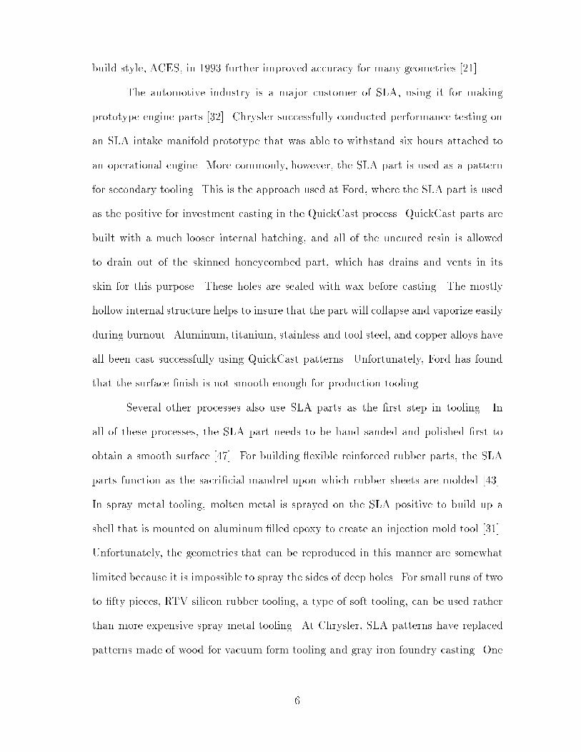
The automotive industry is a major customer of SLA, using it for making
prototype engine parts [32]. Chrysler successfully conducted performance testing on
an SLA intake manifold prototype that was able to withstand six hours attached to
an operational engine. More commonly, however, the SLA part is used as a pattern
for secondary tooling. This is the approach used at Ford, where the SLA part is used
as the positive for investment casting in the QuickCast process. QuickCast parts are
built with a much looser internal hatching, and all of the uncured resin is allowed
to drain out of the skinned honeycombed part, which has drains and vents in its
skin for this purpose. These holes are sealed with wax before casting. The mostly
hollow internal structure helps to insure that the part will collapse and vaporize easily
during burnout. Aluminum, titanium, stainless and tool steel, and copper alloys have
all been cast successfully using QuickCast patterns. Unfortunately, Ford has found
that the surface �nish is not smooth enough for production tooling.
Several other processes also use SLA parts as the �rst step in tooling. In
all of these processes, the SLA part needs to be hand sanded and polished �rst to
obtain a smooth surface [47]. For building exible reinforced rubber parts, the SLA
parts function as the sacri�cial mandrel upon which rubber sheets are molded [43].
In spray metal tooling, molten metal is sprayed on the SLA positive to build up a
shell that is mounted on aluminum �lled epoxy to create an injection mold tool [31].
Unfortunately, the geometries that can be reproduced in this manner are somewhat
limited because it is impossible to spray the sides of deep holes. For small runs of two
to �fty pieces, RTV silicon rubber tooling, a type of soft tooling, can be used rather
than more expensive spray metal tooling. At Chrysler, SLA patterns have replaced
patterns made of wood for vacuum form tooling and gray iron foundry casting. One
6

such casting tool was accurate enough to be used for production parts. Chrysler
has also incorporated SLA patterns into squeeze molding, silicone molding, and resin
transfer molding [22]. Di�erent secondary tooling processes are appropriate when
di�erent materials, batch sizes, and accuracies are required, and SLA parts have
proved adaptable to many such processes.
Technology similar to that developed by 3D Systems is used in a number
of stereolithography systems available abroad [22, 26]. The SOMOS machine was
developed by Du Pont and licensed to Teijin Seiki. The Sony Solid Creation System
(SCS) line includes a model with one of the largest build areas available for any
SFF technology, 40x32x20". Mitsubishi makes the Solid Object Ultra-violet laser
Plotter (SOUP) whose advantages include thin layers and no postcuring. Mitsui
Engineering and Shipbuilding's Computer Operated Laser Active Modeling Machine
(COLAMM) builds parts from the top down: a laser scanner shines up through a
glass plate that forms the bottom of the resin vat, and the elevator platform pulls
the part up between layers. Electro-Optical Systems (EOS) is a German maker of
stereolithography machines. Because of patent considerations, none of these systems
are marketed in the United States.
2.2 Laser Modeling
Quadrax Corporation developed a technology called \laser modeling" that was almost
identical to stereolithography. The main di�erences were that they used a visible light
laser instead of a UV laser, and instead of the support elevator moving down between
each layer, the optics moved up and a new layer of uncured resin was added to the
vat. They claimed that the resins used with visible light lasers settled rapidly so that
layers could be built up more quickly, and that distortion was reduced when the green
walls of the part did not have to move through the uncured resin.
7

Quadrax shipped a product that used this technology, the Mark 1000 Laser
Modeling System, but subsequently sold their patents to 3D Systems and have done
no further work in rapid prototyping. So far, 3D Systems has not incorporated the
above mentioned Quadrax design di�erences into their SLA systems.
2.3 Photosolidi�cation
UV Lamp
Photomask
Glass Plate
Surface Coating!!!!!!!!!!!!!!!!!!!!
11111111111111111111CCCCCCCCCC
!!!!!!#####
Liquid Polymer LayerCCCCCCCCCCCCCCCCCCCCCCCCCCCCCC
@@@
!!!!!!!!!!!!!!!!!!!!!!!!!!!!!!
!!!!
CCCCCCCCCCCCCCCCCCCC
CCCCCCCCCCCCCCCCCCCCCCCCCCCCCCCCC
CCCCCC
CCCCCCCCSolidified Polymer Layers
Support Platform
Deposition Nozzle
!!!!!!!!!!!!!!!!!!!!!!!!
##########!!!!!!####
Photomask Stack
@@@
!!!!!!!!!!!!!!!!!!!!!!!!!!!!!!
Figure 2: Photosolidi�cation: Light Sculpting, Inc.
With Light Sculpting Inc.'s photosolidi�cation technology, a UV lamp cures an entire
layer of photopolymer simultaneously by contact irradiation through a photomask
(Figure 2)[3, 4, 17, 20, 28]. Before part building commences, a photoplotter prints
masks de�ning the negatives of all the layers on transparent �lm and these are loaded
into the machine. Then for each layer, its mask is positioned over a glass plate while
a deposition nozzle deposits a layer of liquid photopolymer onto the bottom surface
of the glass. The layer is exposed to 250 watt UV light through the photomask,
selectively hardening it in areas not protected by the mask. Contact with oxygen
inhibits polymerization; because the photopolymer is not in contact with the air,
energy requirements are reduced by an order of magnitude. A platform supporting
the previous layers is raised to join the new top layer to the part. Then the platform
8

drops back down so that the nozzle can deposit the next layer of photopolymer. The
underside of the glass plate has a proprietary surface coating that allows the polymer
to be separated easily and that inhibits complete polymerization where it contacts
the surface of the layer so that the next layer will adhere to it. The glass plate helps
prevent warpage and shrinkage, as well as supporting cantilevered beams from above.
Light Sculpting claims that this minimizes the number of supports required. A twelve
to �fteen minute postcure is required after building is completed.
There are several advantages to this layer-at-a-time approach. UV lamps are
far cheaper and more reliable than the UV lasers used in stereolithography [29]. Using
a deposition nozzle instead of a vat of liquid makes it easier to change polymers, even
between layers [28]. Build time is thirty to forty seconds per layer regardless of
complexity, but this does not include the time to plot the photomasks. To simplify
the process, Light Sculpting researched replacing the photoplotter and masks with
a liquid crystal array that could be recon�gured in place. Unfortunately, the LCD
materials currently available are quickly damaged by ultraviolet light.
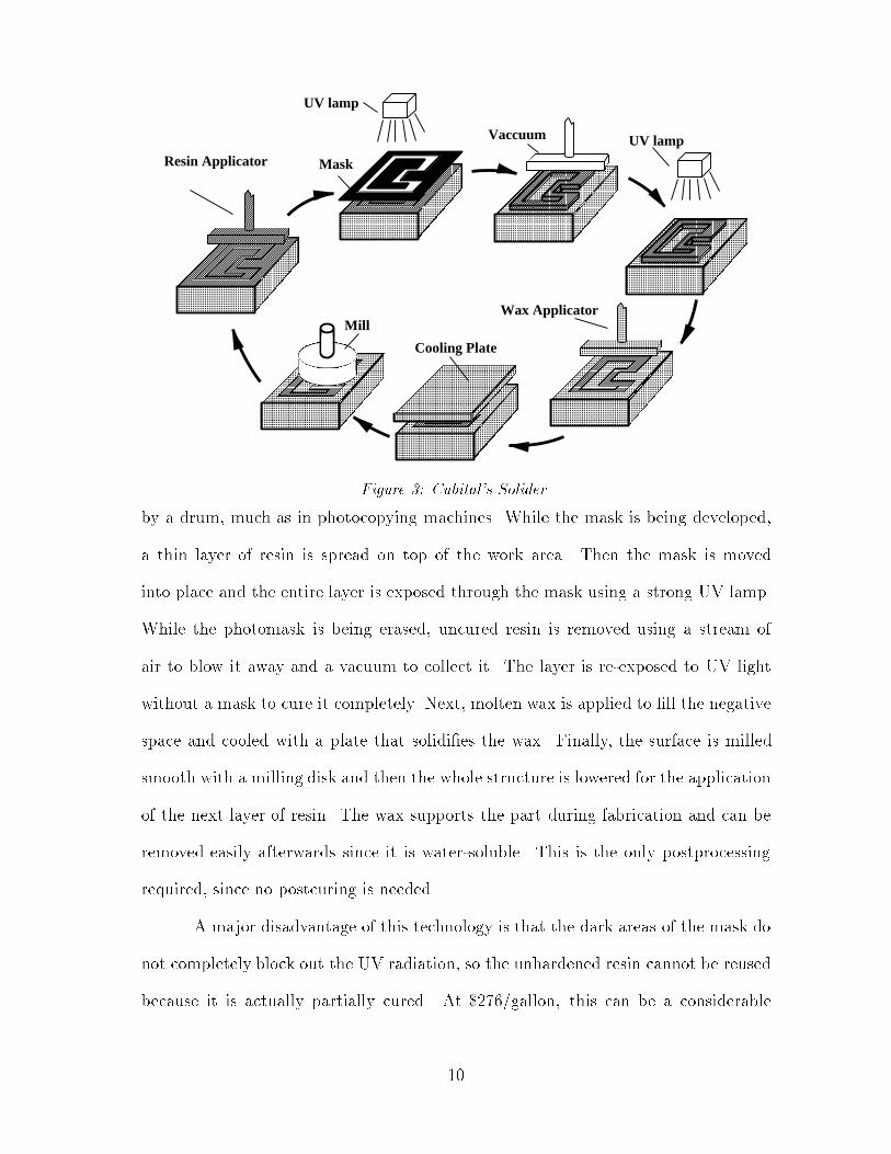
2.4 Solid Ground Curing
Solid ground curing (SGC) was developed by Cubital Ltd., a company based in Israel
that produces a machine called the Solider (Figure 3) [3, 4, 5, 18, 20, 22, 32]. Like
Light Sculpting's photosolidi�cation, solid ground curing builds parts by curing a pho-
topolymer a whole layer at a time, but on a much larger scale; the multi-component
Solider 5600 system weights four and a half tons and measures over thirteen feet long,
four times longer and twice as high as the LSI-1212, the midrange Light Sculpting
system [10, 28].
The Solider makes a mask for each layer by using a plotter to electrostatically
charge selected areas of a glass plate at 300 dpi, upon which toner is deposited directly
9
BBBBBBBBBBBBBBBBBBBBBBBBBBBBBBBB
BBBBBBBBBBBBBBBBBBBBBBBB
BBBBBBBBBBBBBBBBBBBBBBBBBBBBBBBBBBBB
BBBBBBBBBBBBBBBBBBBBBBBBBBBBBBBBBBBB
BBBBBBBBBBBBBBBBBBBBBBBB
BBBBBBBBBBBBBBB@@@@@@@@@@@@@@@@@@@@@@@@@@@@@@@@
@@@@@@@@@@@@@@@@@@
@@@@@@@@@@@@@@@
BBBBBBBBBBBBBBBBBBBBBBBB BBBBB
BBBBB@@@@@@@@@@@@@@@@@@@@@@@@@@@@@@@@
@@@@@@@@@@@@@@@@@@
@@@@@@@@@@@@@@@
BBBBBBBBBBBBBBBBBBBB
!!!!!!!!!!!!!!!!!!!!!!!!
BBBBBBBBBBBBBBBBBBBBBBBBBBBBBBBBBBBBBBBBBBBBBBBBBBBBBB
@@@@@@@@@@@@@@@@@@
BBBBBBBBBBBB
BBBBBBBBBBBBBBBBBBBBBBBB
BBBBBBBBBBBBBBBBBBBBBBBBBBBBBBBB
BBBBBBBBBBBBBBBBBBBBBBBBBBBBBBBBBBBBBBBBBBBB
BBBBBBBBBBBBBBB
BBBBBBBBBBBBBBBBBBBBBBBBBBBBBBBBBBBBBBBBBBBBBBBBBB
@@@@@@@@@@@@@@@@@@
BBBBBBBBBBBB
BBBBBBBBBBBBBBBBBB
UV lamp
Resin Applicator
Cooling Plate
BBBBBBBBBBBBBBBBBB
Vaccuum
@@@@@@@@@@@@@@@@@@
BBBBBBBBBBBBBBB
Wax ApplicatorBBBBBBBBBBBBBBBBBB
UV lamp
@@@@@@@@@@@@@@@@@@
@@@@@@@@@@@@@@@
BBBBBBBB
@@
@@@@@@@@@@@@@@@@@@
@@@@@@@@@@
@@@@@@
BBBBBBBB
@@
@@@@@@@@@@@@@@@@
@@@@
!!!!!!!!!!!!!!!!!!!!!!!!!!!!!!
!!!!!!!!!!!!
Mill
BBBBBBBBBBBBBBBBBBBBBBBB
BBBBBBBBBBBBBBB
@@@@
BBBBBBBBBBBBBBBBBB
BBB
BBB
!!!!!!!!!!!!!!!!!!!!!!!!
!!!!!!!!
!!
Mask
Figure 3: Cubital's Solider
by a drum, much as in photocopying machines. While the mask is being developed,
a thin layer of resin is spread on top of the work area. Then the mask is moved
into place and the entire layer is exposed through the mask using a strong UV lamp.
While the photomask is being erased, uncured resin is removed using a stream of
air to blow it away and a vacuum to collect it. The layer is re-exposed to UV light
without a mask to cure it completely. Next, molten wax is applied to �ll the negative
space and cooled with a plate that solidi�es the wax. Finally, the surface is milled
smooth with a milling disk and then the whole structure is lowered for the application
of the next layer of resin. The wax supports the part during fabrication and can be
removed easily afterwards since it is water-soluble. This is the only postprocessing
required, since no postcuring is needed.
A major disadvantage of this technology is that the dark areas of the mask do
not completely block out the UV radiation, so the unhardened resin cannot be reused
because it is actually partially cured. At $276/gallon, this can be a considerable
10

expense, as well as creating a toxic waste disposal problem. Software control over the
width of the build area mitigates but does not completely solve this problem.
The Solider has several unique build characteristics. Because the entire layer
is exposed at once and rigidly supported by wax at all times, SGC parts don't show
directional distortions within layers, and exhibit less warpage and curl than SLA
parts. The integrated wax support structure makes it possible to build multiple
nested parts with the Solider in a single build cycle with only minimal planning. The
relatively large build area, and the expense of resin to �ll this build area no matter
what percentage of it is actually cured, also encourage building multiple, densely
packed parts. The wax also makes the construction of fully assembled mechanical
systems, such as interlocking gears, possible.
SGC parts have been used successfully as patterns for secondary tooling. The
service bureau General Pattern typically builds twenty �ve to thirty parts at a time
with their Solider system out of an epoxy-like composite that is used to create liquid
injection molds [32]. Solider parts can also be used as patterns for silicon rubber,
epoxy, or spray metal tooling, and sand casting [10].
3 Deposition Approaches
3.1 Fused Deposition Modeling
In fused deposition modeling (FDM), developed by Stratasys Inc., the part is built up
in layers formed by extruding melted wax or plastic (Figure 4) [3, 4, 5, 6, 9, 20, 22].
The modeling material is supplied as a thin, .05 inch diameter �lament that feeds o�
of a spool into the FDM head. Both machinable and investment casting wax, and
two types of thermoplastics (polyole�n and polyamide), are currently available in
�lament form for use with the Stratasys system. Inside the FDM head, the �lament
11

is heated to just above its melting temperature and then pumped out through a
nozzle. Meanwhile, the head, controlled by an NC tool path, moves to trace out the
cross section of the layer. The melted material adheres to the platform for the �rst
layer, otherwise to the previous layer, hardening in about a tenth of a second. After
each layer has been deposited, an elevator adjusts the distance between the platform
and the FDM head so that the next layer can be deposited on top of the previous
layers. It is important that the temperature and head velocity are kept constant,
even when moving between layers, to prevent visible seams and surface irregularities.
!!!!!!!!!!!!!!!!!!!!!!!!!!!!!!!!!!!!!!!!!!!!!!!!!!!!!!!!!!!!!!!!!!!!!!
Build Platform
!!!!!!!!!!!!!!!!!!!!
Supports
FDM Head
Part>>>>>>>>>>
!!!!!!!!!!!!!!!!!!!!
!!!!!!!!!!
!!!!
Filament Spool Nozzle
****
******
????????????????????????????????????
Filament
!!!!!!!!!!!
Figure 4: Fused Deposition Modeling
The main advantages of this system are that no postcuring is required, and
it is fairly safe because the materials are non-toxic and no lasers are involved. As a
result, it is one of the few systems that can be used in an o�ce environment for actual
desktop manufacturing, though temperatures must be tightly controlled. Conceptual
models can be made from machinable wax and sturdier prototypes for testing can be
made from plastics. Machinable wax prototypes can also be used in the spray metal
tooling process to produce molds for injection molding. Investment wax has been
used successfully for investment casting.
The Stratasys FDM system can take 3D CAD data for input (either solid,
12

surface, or wireframe models), in addition to the faceted .STL �les used by virtually
every other commercial SFF system. These 3D �les are processed by the NURBS
based \QuickSlice" slicing software. As a result, parts produced with FDM don't
show the faceting artifacts often seen on parts produced by other SFF systems. A
disadvantage of the system is that all of the slicing must be completed before the
actual building starts; only then are NC tool paths for each slice downloaded to control
the movement of the extrusion head. This explicit control of the head movement
also makes it possible to download custom tool paths in place of the automatically
generated QuickSlice tool paths. Debasish Dutta at the University of Michigan has
developed experimental adaptive slicing software for the FDM system that adjusts
the height of each layer based on the local geometry to better balance build speed
and resolution [13].
Support structures are a bigger problem for FDM than for any other com-
mercialized SFF technology. Since there is no liquid photopolymer or powder bed to
support the top layer being deposited, supports will be required anywhere that the
top layer extends more than minimally over the pro�le of the previous layer. The
FDM software generates dense, corrugated support structures for these areas, trying
to balance strength with ease of removal. To increase the latter, a second extrusion
head can be used to deposit a weakly bonded layer of a separate material between the
part and the support to create a \break away support structure." Hollow geometries
with at or nearly at surfaces on the top are poor candidates for FDM because there
would be no way to remove the supports from the interior.
3.2 Ballistic Particle Manufacturing
Ballistic particle manufacturing (BPM) is a technology that has been under develop-
ment for several years at the small South Carolina �rm of Perception Systems, Inc.
13

[3, 4, 22, 29, 36]. BPM uses drop-on-demand ink-jet printing technology modi�ed to
\print" with drops of molten wax. The �fty micron drops of wax are sprayed at a
speed of 10,000 per second; thirty two such jets are used to increase the build rate.
The molten wax bonds to the part by melting the outer layer of the existing structure
upon contact. Support structures are simultaneously built up out of polyethylene
glycol, a water-soluble wax. After part building is completed, the support structures
are dissolved using warm water. The wax parts can be used for investment casting
or as design prototypes.
The original system builds up parts in cross sectional layers, lowering the part
after each layer is completed to allow the next layer to be deposited. The thickness
of each layer is dynamically adjusted by measuring the distance to the layer below
and adjusting the amount of wax deposited based on the variation. The position of
the print head along the x and y axes is controlled by servo and stepper motors.
BPM has also been used for fabrication of rotationally symmetric metal parts
by spraying molten metal at a rotating mandrel. The technology has the potential to
be used for truly freeform, non-layered fabrication because the droplets can be ejected
at many angles, not just from straight overhead.
4 Powder Bed Approaches
4.1 Three-Dimensional Printing
A group at MIT developed \three-dimensional printing" technology and licensed it
to Soligen, which sells parts produced on its Direct Shell Production Casting (DSPC)
system (Figure 5). In 3D printing, a powdered material is distributed a layer at a
time and selectively hardened and joined together by depositing drops of binder from
a mechanism similar to that used for ink-jet printing. The main materials used are
14

ceramics: alumina particles and colloidal silica binder [3, 4, 20, 22, 38, 37, 32].
CCCCCCCCCCCCCCCCCCCCCCCCCCCCCCCCCCCCCCCCCCCCCCCCCCCCCCC
BBBBBBBBBBBBBBBBBB
!!!!!!!!!!!!!!!!!!!!!!!!!!!!!!!!!!!!!!!!!!!!!!!!!!!!!!!!!!!!!!!!!!!!!!!!!!!!!!!!!!!!!!!!!!!!!!!!!!!!!!
BBBB
BBBBBBBBBBBBBBBB CCCCCCC
CCCCCCCCCCCCCCCCCCCCCCCCCCCC---
!!!!!!
@@@@@@@@@@@@@@@@@@@@@@@@
@@BB
BBBBBBBB
Powder HopperPrint Head
Part
Loose Powder
Roller
Binder
!!!!!!!!!!!!!!
!!!!!!!!!!!!!!
BBBBBBBBBBBBBBBBBBBBBB
BBB
Piston
BBBBBBBBBB
CCCCCCCCCCCCCCCCCCCCCCCCCCCCCCCCCCCCCCCCCCCCCCCCCC
!!!!
!!!!!!
Figure 5: 3D Printing
For each layer, a powder hopper and roller system distribute a thin layer of
powder over the top of the work tray. Adapted continuous-jet printing nozzles apply
binder during a raster scan of the work area, selectively hardening the part's cross
section. Then a piston lowers the part so that the next layer of powder can be applied.
The loose powder that wasn't hardened remains and acts as a support for subsequent
layers. With ceramics, after the part has been built up, the entire tray is �red in a
kiln, and then loose powder is removed.
The 3D printing process is quite exible in choice of materials. Any combi-
nation of a powdered material with a binder that has low enough viscosity to form
droplets could potentially be used. In addition to ceramics, plastic, metal, and metal-
ceramic composite parts can be made. A potential disadvantage is that the parts will
always be porous because of density limitations on the distribution of dry powder.
For metal-ceramic composites, the porous ceramic shape is produced using 3D print-
ing and subsequently pressure in�ltrated with molten metal to form the composite.
The main focus with ceramics, however, has been on ceramic shells and cores that
are used for casting metal.
15

In traditional investment or lost-wax casting, ceramic shells are made by a
multi-step process. First a metal die tool is made to de�ne the negative of the part,
and if the part has hollows, dies are also made for cores that de�ne the internal
geometry. The cores are molded, and then a wax positive is molded around the cores
using the primary tool. Wax positives are next attached together with a tree of wax
that de�nes metal inlets and gas vents. The whole wax structure is repeatedly dipped
into a ceramic slurry, allowing it to dry between dippings. Then the wax is melted
out and the ceramic shell is �red. Finally the metal can be cast in this ceramic mold.
As the metal hardens and shrinks, the shell and core crack. The shell is broken o�
and the cores are chemically dissolved during the �nal cleaning step.
By using 3D printing to produce the ceramic shells with integral cores di-
rectly from the CAD model, a number of disadvantages of the traditional process are
avoided. Most signi�cant is that the metal dies are typically expensive and time con-
suming to produce, with lead times ranging from two to six months. For small batch
runs the cost of tooling can be prohibitive. With 3D printing, designs can prototyped
quickly and economically. Furthermore, traditional lost wax casting methods require
multiple pattern transfers, each with a potential loss of accuracy, that are eliminated
by printing the ceramic shell directly. It is not clear whether the resolution of cur-
rent 3D printing systems is high enough to realize this advantage, however. Finally,
printing integral cores means that they will be precisely located and not subject to
shifting when embedded in the wax, allowing thinner walls to be cast, and the cores
can be made hollow, leaving less material to be leached out.
Soligen's DSPC software takes a CAD model of the positive shape and pro-
duces a model of the negative ceramic casting mold to send to the 3D printing system.
Diverse metals, including copper, bronze, aluminum, cobalt chrome, stainless steel,
16
and tooling steel, have been successfully cast in the ceramic shells produced by this
process. Metal parts can generally be produced in two to three days.
One of the current areas of research in 3D printing at MIT is better curve
�tting. With continuous ink-jet printing a steady stream of drops is output, with the
drops that are not to be printed electrostatically de ected into a collection tube. It is
possible to modify the de ection electronics to more precisely control the placement
of the drops that are deposited. This is done at the edges of the part to help control
aliasing. Unfortunately, since the input is triangulated .STL �les, the droplets are
only being placed closer to a faceted approximation of the actual curved boundary.
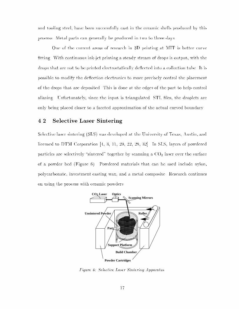
4.2 Selective Laser Sintering
Selective laser sintering (SLS) was developed at the University of Texas, Austin, and
licensed to DTM Corporation [4, 3, 11, 20, 22, 29, 32]. In SLS, layers of powdered
particles are selectively \sintered" together by scanning a CO2 laser over the surface
of a powder bed (Figure 6). Powdered materials that can be used include nylon,
polycarbonate, investment casting wax, and a metal composite. Research continues
on using the process with ceramic powders.
Build Chamber
CO2 LaserScanning Mirrors
@
Support Platform
CCCCCCCCCCCCCCCCCCCCCCCC
CCCCCCCCCCCCCCCCCCCCCCCCCCCCCCCCCCCCCCCCCCCCCCCC
Part
@@@@@@@@@@@@@@@@@@@@@@@@
CCCCCCCCCCCCCCCCCCCCCCCC
????????????????????????????????????>>>>>>>>>>
Roller
Powder Cartridges
Optics
Unsintered Powder
Figure 6: Selective Laser Sintering Apparatus
17
Each layer of powder is delivered to the cylindrical building area by a cartridge
feeding system and a roller that distributes and levels the powder. Then the powder
is heated to just below its melting point; inert nitrogen gas �lls the rest of the build
chamber to prevent explosions and oxidization. During a raster-scan of the work area,
the laser beam is modulated so that only the cross section of the desired geometry is
heated su�ciently for the viscosity of the particles to drop enough for them to fuse.
Then the powder tray is lowered and the next layer of powder deposited. Unhard-
ened powder supports the part being built, eliminating the need for separate support
structures. After part building is completed, the part is raised up and much of the
unsintered powder falls away. A layer of powder is left in place around the part to
insulate it so that it won't cool too rapidly. Once the part has cooled, this powder
must be removed by hand with brushes, compressed air, and dental tools.
With DTM's RapidTool process, additional processing steps are required. The
parts are made out of a mixture of approximately 95% iron and 5% polymer. After
the green part is cleaned, it is put in a furnace to burn out the polymer binder. The
remaining metal is sintered, but it is still porous. Copper is in�ltrated to make a
fully dense metal tool. Tooling produced by this process can be used to manufacture
as many as 50,000 parts using standard injection molding equipment.
SLS has been widely used in both the aerospace and automotive industries,
primarily for producing polycarbonate parts that are wax-coated for investment cast-
ing. Polycarbonate is not as sensitive to temperature changes as wax, which makes it
more suitable for shipping, whereas wax may melt or become brittle and break if ship-
ping temperatures are too hot or too cold. Finer details, including thinner walls, are
also possible to reproduce with polycarbonate. If the polycarbonate part is going to
be used for other purposes, it can be treated with an epoxy resin to make it smoother
18

and stronger, or it can be sanded by hand [50]. Nylon parts are often durable enough
to be used directly for testing snap �ts and assemblies, and can withstand tempera-
tures up to 150�F. The SLS parts are primarily used as patterns for prototypes; once
the design is �nalized traditional tooling is generally used for production.
5 Sheet Based Subtractive Approaches
All of the SFF technologies discussed above are additive. The layers are formed
by fusing, hardening, or depositing material in the shape of the cross section. In
subtractive SFF technologies, the layer is formed by removing the material that is
the negative of each cross section.
5.1 Stack First
BBBBBBBBBBBBBBBBBBBBBBBBBBBBBBBBBBBB
BBBBBBBBBBBBBBBBBBBBBBBBBBBBBBBBBBBBBBBBBBBBBBBB
BBBBBBBBBBBBBBBBBBBB
Platform
!!!!!!!!!!!!!!!!!!!!!!!!!!!!!!!!!!!!
!!!!!!!!!!!!!!!!!!!!!!!!!!!!!!!!!!!!!!!!!!!!!!!!
!!!!!!!!!!!!!!!!!!!!
!!!!!!!!!!!!!!!!!!!!!!!!!!!!!!!!!!!!
!!!!!!!!!!!!!!!!!!!!!!!!!!!!!!!!!!!!!!!!!!!!!!!!
!!!!!!!!!!!!!!!!!!!!
!!!!!!!!!!!!!!!!!!!!!!!!!!!!!!!!!!!!
!!!!!!!!!!!!!!!!!!!!!!!!!!!!!!!!!!!!!!!!!!
!!!!!!!!!!!!!!!!
!!!!!!!!!!!!!!!!!!!!!!!!!!!!!!!!!!!!
!!!!!!!!!!!!!!!!!!!!!!!!!!!!!!!!!!!!!!!!!!
!!!!!!!!!!!!!!!!
!!!!!!!!!!!!!!!!!!!!!!!!!!!!!!!!!!!!
!!!!!!!!!!!!!!!!!!!!!!!!!!!!!!!!!!!!!!!!!!!!!!!!
!!!!!!!!!!!!!!!!!!!!
!!!!!!!!!!!!!!!!!!!!!!!!!!!!!!!!!!!!
!!!!!!!!!!!!!!!!!!!!!!!!!!!!!!!!!!!!!!!!!!!!!!!!
!!!!!!!!!!!!!!!!!!!!
!!!!!!!!!!!!!!!!!!!!!!!!!!!!!!!!!!!!
!!!!!!!!!!!!!!!!!!!!!!!!!!!!!!!!!!!!!!!!!!
!!!!!!!!!!!!!!!!
!!!!!!!!!!!!!!!!!!!!!!!!!!!!!!!!!!!!
!!!!!!!!!!!!!!!!!!!!!!!!!!!!!!!!!!!!!!!!!!
!!!!!!!!!!!!!!!!
BBBBBBBBBBBBBBBBBBBBBBBBBBBBBBBBBBBBBBBBBBBBB
!!!!!!!!!!!!!!!!!!!!!!!!!!!!!!!!!!!!
!!!!!!!!!!!!!!!!!!!!!!!!!!!!!!
!!!!!!!!!!!!!!!!!!!!
!!!!!!!!!!!!!!!!
!!!!!!!!!!!!!!!!
Laser
@@
Optics
@@@@
Positioner Roller
Waste Collection Spindle
Tiled Waste Area
Part Cross Section
!!!!!!!!!!!!!!!!!!!!!!!!!!!!!!
!!!!!!!!!!!!!!!!!!!!!!!!!
!!!!!!!!!!!!!!!!!!!!
!!!!!!!!!!!!!!!!
!!!!!!!!!!!!!!!!!!!!!!!!!!!!!!!!!!!!!!!!!!
BBBBBBBBBBBBBBBBBBBBBBBBBBBBBBBBBBBBBBBBBBBBBBBBBBBBBBBBBBBBBBBBBBBBBBBBBBBBBBBBBBBBBBBBBB
&&&&&&&&&&&&&&&&&&&&&&&&&&&&&&&&&&&&
BBBBBBBBBBBBBBBBBB
&&&&&&&&
Delivery Spindle
!!!!!!!!!!!!!!!!!!!!!!!!!!!!!!
!!!!
!!!!
Part Stack
Figure 7: Laminated Object Manufacturing
Laminated object manufacturing (LOM), developed by Helisys, is the only fully auto-
mated subtractive SFF technology commercially available [4, 3, 5, 20, 16, 22, 25, 33].
Laminated parts are produced from paper, plastic, foil, or composite sheets, all coated
with a thermally activated adhesive. The material is supplied in a roll that is placed
on a delivery spindle, unrolled across the top of the work surface, and collected on the
19
other side by a waste collection spindle (Figure 7). At the start of the cycle for each
layer, a heated roller bonds the rectangular \work area" on the sheet to the top of the
part stack containing the partially built up part. A laser cuts the outline of the new
layer and the outline of the work area. The negative space in between, and any holes
in the cross section, are crosshatched into \tiles" by the laser to facilitate eventual
removal. Then the part stack is lowered, allowing the waste collection spindle to roll
up the unbonded waste material surrounding the work area and pull a new section of
the roll across to cover the work surface. Then the stack is raised back up to contact
the clean sheet, ready to be bonded for the next cycle. The stack is measured after
each layer, so that variations in layer thickness can be accounted for when determin-
ing the contour to cut. LOM parts can be used as patterns for secondary tooling
processes, including RTV molding, spray metal tooling, and investment casting.
Despite the tiling, removal of the waste material from the part block at the end
of the process is problematic. Tiling alone does nothing to prevent horizontal part
surfaces from bonding to the waste material above or below. The software identi�es
at horizontal surfaces, either up or down facing, and uses a �ner crosshatching
pattern called burnout where they meet the scrap material. For up facing surfaces,
the burnout is done on the top part layer; for down facing surfaces, it is done on the
layer below them. Burnout does not a�ect the adhesive bonding, but it weakens the
underlying material so that it can be broken o� more easily. Initially the software
did not identify horizontal surfaces that resulted from stair-stepping in reproducing
angled surfaces, so these surfaces were not burned out. This may have been corrected
in more recent software releases. The �nal part always needs to be carefully broken
out by hand to avoid delamination.
Another issue in waste removal is hollows within the part. Parts with com-
20

pletely enclosed hollow areas cannot be built using LOM since the waste material will
be permanently trapped inside. Helisys's initial prototypes used a suction system
to remove waste as the part was being built, but this was not incorporated into the
initial commercial systems, which retain the waste material to support the part. Even
for hollows that are not completely enclosed, it may not be easy to get inside them
to loosen waste bonded to horizontal surfaces, and the waste tiles may be too big to
�t through openings for removal.
LOM does o�er some advantages over other rapid prototyping technologies.
The waste material acts as an automatic support structure, supporting the part and
maintaining the exact position of \islands" in the part that won't be connected until
higher layers have been attached. Since layers are cut after they have been bonded,
shrinkage is not a concern. Any material manufacturable in sheets coated with adhe-
sive can potentially be used, and will often be inexpensive as well. (The early paper
used was actually waxed butcher's paper, with the wax coating acting as a thermally
activated adhesive.) With a modi�ed system for applying the new sheets, it would
be possible to change the color or even material for each layer. Because LOM is
subtractive, only the outline of each layer needs to be cut, rather than tracing out the
entire interior of each cross section, for a potential speed advantage. This advantage
is o�set by the need to tile the negative space, however, particularly if the part volume
is small compared to the work area, and current LOM systems are slower than other
SFF systems for most applications.
Other disadvantages of LOM include delamination, anisotropic material prop-
erties, the creation of large amounts of scrap material (though it is at least non-toxic),
limitations on part geometry dictated by waste material removal considerations, and
warpage caused by internal stresses generated by the heat of laser cutting.
21

In addition to Helisys, a Swedish company, Sparx, makes a subtractive rapid
prototyping system that cuts layers out of polystyrene. The waste material removal
and stacking of layers has to be performed manually, however.
5.2 Stack Last
A laminated technology called Computer-Aided Manufacturing of Laminated Engi-
neering Materials (CAM-LEM) is under development at Case Western Reserve Uni-
versity and CAM-LEM, Inc.[8, 30]. A laser cuts each cross section from a thin sheet
of material. In future systems, the laser will also approximate the edge tangents
at the pro�le. A selective-area gripper lifts up the positive of the cross section and
transfers it to a stacking station, preserving the position of all the elements. This
cutting and stacking operation has been performed successfully with ceramics, paper,
cardboard, plexiglass, and styrofoam. Then the laser cuts the same pro�le out of a
sacri�cial material and the complement of the cross section is transferred to the stack-
ing station, so that the entire layer will be of a uniform height when the next layer
is applied. Thus a support structure is generated automatically from the sacri�cial
material using the same tool paths. The layers are tacked together as they are built
up, and after the �nal layer is attached, the part block is laminated for strength using
an isostatic press. With ceramics, a �nal �ring step burns out the sacri�cial mate-
rial and completely fuses the ceramics layers, so that the �nished piece will exhibit
isotropic material properties.
6 Hybrid: CMU's Shape Deposition Manufac-
turing
Shape deposition manufacturing (SDM) is a complex SFF technology being developed
at Carnegie Mellon's Engineering Design Research Center [15, 46, 45]. SDM's main
22
innovations are software support for embedded components and multiple materials,
and the use of 5-axis NC milling to shape the edges of individual layers. A robotic
pallet systemmoves the part between stations that deposit and shape the layers. Each
layer is composed of a combination of primary material(s) and a sacri�cial support
material deposited in the complementary shape.
The 3D description of a part is adaptively sliced into layers of di�erent thick-
nesses, based on the location of undercut features. These are true 3D layers, unlike
the 2.5D layers used by virtually all other SFF process planners. Each layer is further
subdivided if it has both undercut and overcut features. If there are any undercut
features, the support material is �rst deposited at their edges in near-net shape (Fig-
ure 8 a) by a thermal deposition process (thermal spraying or weld-based for metals).
Then the part is robotically transferred to the shaping station, where a 5-axis NC
mill machines the exact complement of the undercut feature into the support mate-
rial (Figure 8 b). Next the part is returned to have the primary material deposited
(Figure 8 c); undercut features in the primary material will thus be shaped by the
support material. Then the part is transferred back to the shaping station to mill
overcut features (Figure 8 d). Finally, the part is returned to the deposition station to
have support material deposited around any overcut features, and the layer is milled
smooth (Figures 8 e, f). If multiple primary materials are used, similar analysis of un-
dercut and overcut features between the materials will be required to deposit and mill
the layer's segments in the proper order. After each milling step, the part is trans-
ferred to a cleaning station to have cutting uids removed. Additional intermediate
operations can be performed on the layers, such as embedding electronic components
or shot peening (bombarding the area with small pellets) to relieve internal stresses.
A combination of materials that has been used successfully with this process is
23

BBBBBBBBBBBB
BBBBBBBBBBBBBBBBBBBBBBB
BBBBBBBBBBBB
BBBBBBBBBBBBBBBBBBBBBBB
BBB
>>>>>>>>>>>>>>>>>>>>>>>>>>>>>>>>>>>>>>>>>>>>>>
BBBBBBBBBBBB
BBBBBBBBBBBBBBBBBBBBBBB
BBBBBBBBBBBB
BBBBBBBBBBBBBBBBBBBBBBB
BBB
BBBBBBBBBBBBBBBB
>>>>>>>>>>>>>>>>>>>>>>>>>>>>>>>>>>>>>>>>
BBBBBBBBBBBB
BBBBBBBBBBBBBBBBBBBBBBB
BBBBBBBBBBBB
BBBBBBBBBBBBBBBBBBBBBBB
BBBBBBBBBBB
>>>>>>>>>>>>>>>>>>>>>>>>>>>>>>>>>>>>>>>>>>>>>>
>>>>>>
BBBBBBBBBBBB
BBBBBBBBBBBBBBBBBBBBBBB
BBBBBBBBBBBB
BBBBBBBBBBBBBBBBBBBBBBB
BBB
>>>>>>>>>>>>>>>>>>>>>>>>>>>>>>>>>>>>>>>>>>>>>>>>>>>>>>>>
BBBBBBBBBBBB
BBBBBBBBBBBBBBBBBBBBBBB
BBBBBBBBBBBB
BBBBBBBBBBBBBBBBBBBBBBB
BBB
>>>>>>>>>>>>>>>>>>>>>>>>>>>>>>>>>>>>>>>>
BBBBBBBBBBBB
BBBBBBBBBBBBBBBBBBBBBBB
BBBBBBBBBBBB
BBBBBBBBBBBBBBBBBBBB
BBBBBBBBBBBB
>>>>>>>>>>>>>>>>>>>>>>>>>>>>>>>>>>>>>>>>
(b) (f)
support material build material
mill
(a) (c) (e)
(d)
Figure 8: Shape Deposition Manufacturing
stainless steel as the primary material with copper as the sacri�cial support material.
The molten copper can be deposited on the solid stainless steel without melting it
because copper has a lower melting point, and the molten steel can be deposited
on the solid copper without melting it because copper has a much higher thermal
conductivity. At the end of the process, the copper is dissolved with nitric acid,
leaving the stainless steel part intact.
SDM accepts part geometry in the ACIS [40] format, allowing curved surfaces
to be expressed as NURBS. Process planning is also performed using ACIS models.
Unfortunately, according to Lee Weiss, they have not found ACIS to be as robust as
they had hoped [44].
7 Comparison
Rapid prototyping technologies can be compared using a variety of criteria, with cost
and speed generally considered the most important. Users are also concerned about
what the part looks like: its accuracy and surface �nish, what materials can be used,
what geometries can be reproduced, and how large a part can be built. Taking a
longer view, a process that can be scaled for greater speed or larger build area will
24
have a better chance of survival as the technology matures, and a more environmen-
tally friendly process will win adherents as \green" manufacturing becomes a greater
concern. This section compares the SFF technologies that have been commercialized.
7.1 Cost
Operating SFF equipment is an expensive proposition, requiring an minimum ex-
penditure of almost $100,000 on the machine alone, plus maintenance, computers,
materials, and in some cases, a postcuring apparatus (Table 1). In terms of capital
investment, solid ground curing with Cubital's Solider 5600 is probably the most ex-
pensive SFF technology, rivaled only by high-end SLA stereolithography machines.
The SLA-500 costs $500,000 and the Solider 5600 costs $445,000, but the size and
weight of the Solider necessitates a larger facilities investment. On the low end,
systems for about $100,000 are available for laminated object manufacturing, photo-
solidi�cation, and also stereolithography, for smaller build areas. Systems for LOM
and photosolidi�cation are also available with large build areas for about $200,000.
Maintenance costs are another consideration. In general, lasers require fre-
quent and costly replacements, making for more expensive systems than those that
use UV lamps. The lasers used by 3D Systems's stereolithography machines, for ex-
ample, have an expected lifetime of 2,000 hours, compared with the LSI-1212's UV
lamps with an expected lifetime of 10,000 hours. An SLA machine operated daily
for one eight hour shift would need a new laser about once a year, but since it can
run unattended, many large jobs are left to run overnight, and the yearly number of
laser replacements could be higher. Chrysler reports replacing lasers roughly every
six months after 4,000 hours of use. At a cost of $25,000 per laser for the SLA-500
or $9,200 for the SLA-250 [48], this can be a considerable expense. In contrast, the
UV lamps used in the LSI-1212 cost $200. SLA maintenance contracts that include
25

Technology Base Cost Service Postcurer Chrysler [22, 49]
Contract Cost Part Cost
Stereolithography $10K[48]
SLA-190/20 $110K[2]
SLA-250/30 $250K[2] $36K[22] $110-130
SLA-500/30 $500K[2] $85K[22] $150-190
Photosolidi�cation
LSI-0609 $100K[20]
LSI-1212 $105K[28] $6K[28] $8K[28]
LSI-2224 $160K[20]
SGC n/a
Solider 5600 $445K[10] $69K[10] $90-380
Solider 4600 $275K[10] $49K[10]
3D Printing
DSPC (Soligen) (service bureau)
FDM n/a
FDM-1600 $170K�[41] $7K[41]
3D Modeler $182K[4, 20] $7K[22] $150-320
SLS n/a
Sinterstation 2000 $330K[12] $68K[22] $180-200
LOM n/a
LOM-1015 $119K[19] $4K[19] $90-110
LOM-2030 $234K[19] $6K[19]
Table 1: Comparison of Rapid Prototyping Technologies : Costs. The Chrysler
Part Cost �gures are the range of published estimates of the actual cost to
produce a small benchmark part on several systems, based on operation data
gathered by Chrysler. For more details, refer to Appendix A. (�FDM-1600
quote does not include cost of required Unix workstation.)
laser replacements can be purchased from 3D Systems for $36,000 and $85,000 for
the SLA-250 and SLA-500 respectively [22], as compared with basic service contracts
at $25,000 and $45,000. On the other hand, the large number of non-laser compo-
nents in the Cubital system makes it more likely that one of them will need servicing,
re ected in Cubital's high basic service contract price.
Per-part marginal cost can also be extremely high with the SGC Solider sys-
tem. Material costs are higher, because the support wax and unhardened resin must
be discarded after each build. Furthermore, long build times combined with the cost
26

of attended operation can make parts several times more expensive to produce with
the Solider than with other systems, according to Terry Wohlers [49]. But, if nu-
merous parts are e�ciently packed into the build area and built at the same time (a
common practice with the Solider), the cost of the attendant is amortized over all
parts, and the total cost per part could actually be lower with SGC than for any of
SLS, SLA, LOM, or FDM, as reported by Au and Wright [4].
That estimating the costs of di�erent SFF technologies is inherently subjective
is brought into sharp focus by the fact that the authors of both the articles cited
obtained their data from the same Chrysler benchmarking study of the manufacture
of the same 1.5x1.5x3" speedometer part, yet one found SGC to be the most expensive
technology for manufacturing the part, and the other found it to be the least expensive
technology. Running the more expensive machines infrequently or without packing
their larger build area can raise per-part costs dramatically.
By adjusting parameters such as the shape, size, or number of test parts
carefully, most any company could make a case that their system is the most cost
e�ective. Potential customers would need to know the types, sizes, and number of
parts they will be producing in order to evaluate the true cost of each system for their
particular business. For more details of the Chrysler benchmark and an interpretation
of the results, refer to Appendix A.
7.2 Speed
As with cost, SFF speed can be measured in many ways (Table 2). Of the additive
approaches to SFF, Cubital's Solider 5600 is one of the fastest when measured by the
total cubic inches per hour it is capable of producing. This is the result of layer-at-
a-time fabrication over a large build area. Each layer only takes sixty �ve seconds,
regardless of the area of resin hardened, for an estimated build rate (with layers of
27

.005" and the build volume 33% �lled) of 26 inches3/hr (.33 vertical inches/hour).
With LSI's photosolidi�cation machines, the time to form each layer is even shorter,
only thirty to forty seconds, for a faster estimated build rate of .6 vertical inches/hour
with layers of .005", but this does not include the time to slice the input �le and
produce the masks, which must be done before part building commences.
Technology Preprocessing Build Speed Postprocessing
Stereolithography slice, support postcure,
generation remove supports
SLA-190/20 30"/sec scan[2]
.25 in3/hr[20]
SLA-250/30 30"/sec scan[2]
.75-4 in3/hr[10, 48]
SLA-500/30 200"/sec scan[2]
3 in3/hr[10]
Photosolidi�cation slice, print masks postcure,
remove supports
LSI-0609 40 sec/layer[26]
LSI-1212 30 sec/layer[28]
SGC (no pre-slice) wash o� wax
Solider 5600 65 sec/layer [10]
26 in3/hr[10]
.33 vert"/hr[20]
Solider 4600 120 sec/layer [10]
10 in3/hr[10]
3D Printing (no pre-slice) remove powder,
�re in kiln
DSPC (Soligen) .39 vert"/hr[20]
FDM slice, tool path and remove supports
support generation
SLS (no pre-slice) remove powder
Sinterstation 2000 .75 in3/hr[20] y
LOM (no pre-slice) .25{.33 vert"/hr[20] breakout
LOM-1015 15"/sec scan[20]
LOM-2030 24"/sec scan[20]
Table 2: Comparison of Rapid Prototyping Technologies : Speed
Point-to-point laser additive approaches, which include SLA, SLS, and 3D
28

printing, tend to be slower. Cubital estimates the build rate of SLA machines to
be only .75{3 in3/hour [10], and Plynetics, an independent service bureau in San
Leandro, CA, gives an even lower estimate of .25 in3/hour for the entry level SLA-
190 system[20]. Plynetics estimates the build rate for SLS to be three times faster, .75
in3/hr [20]. Soligen claims a .39 vertical inches/hour build rate for DSPC [20]. The
vertical build speed of a point-to-point approach, however, is an almost meaningless
statistic without knowing the size and shape of the cross sections of the layers being
produced. If this measurement was taken for a part that was 33% solid and �lled the
entire build area, it would be a build rate of better than 10 in3/hour.
With LOM, a subtractive approach, the ratio of the available build volume that
is �lled by the part has an enormous impact on speed measurements. A smaller part
could actually take longer to build because of the time required to cut the negative
of the part into tiles for later removal. Helisys reports a build rate of .25{.33 vertical
inches per hour [20].
For small parts, FDM can achieve impressive speeds. Stratasys reports a build
speed of two vertical inches/hour for a 3.5" diameter turbine blade [20]. FDM is also
a point-to-point approach to SFF, so this build speed cannot be generalized to other
geometries. Furthermore, FDM can be run with signi�cantly thicker layers than many
of the other processes, achieving better speed at the cost of lower accuracy.
The Chrysler benchmarking study [49] of the time to produce a single speedome-
ter part can be used to verify these �gures (see Table 7 in Appendix A for the raw
numbers). Chrysler found that FDM had the fastest machine build time, when run
with thick layers, of a little over two hours (� 1.5 vertical inch/hr, consistent with He-
lisys's reported speeds), though with thinner layers the build time increased to eight
hours, demonstrating how sensitive SFF technologies can be to the choice of build pa-
29

rameters. The second fastest machine build time of three hours was achieved by SLS
(� .75 in3/hr if the part is assumed to �ll 33% of its bounding box volume, consistent
with the Plynetics estimate). With both the SLA-250 and the SLA-500, the part took
approximately �ve hours to build (� .45 in3/hr, faster than the Plynetics estimate
for the SLA-190 but slower than the Cubital estimates), and was only twenty two
minutes faster with the more powerful SLA-500 than with the SLA-250. This small a
di�erence may seem surprising considering that the scan speed of the SLA-500's laser
is over �ve times faster, but unfortunately the higher scan speed means that the laser
doesn't penetrate as deeply, so it can only be run at full speed with much thinner
layers. The slowest machine build times of ten hours were from SGC and LOM (�
.22 in3/hr). This is somewhat misleading because both these machines have build
areas far larger than the part being produced, and neither would be slowed down by
packing the build area with multiple parts or a larger part, which would considerably
a�ect the speed of the other machines being benchmarked.
In addition to the actual machine time during the build, the pre- and post-
processing operations can add signi�cantly to the total time to produce parts. Prepro-
cessing may include creating support structures, processing the input �les, including
merging and slicing multiple part �les, and machine setup time. For stereolithograpy
on SLA machines, FDM on Stratasys machines, and photosolidi�cation on Light
Sculpting machines, the part building cannot begin until slicing is completed, so a
part that is taller or built with thinner layers will require longer preprocessing. This
is not an issue for Helisys's LOM, Cubital's Solider, or DTM's Sinterstation, which
slice in parallel with building.
Postprocessing may include cleaning excess material from the �nished part,
such as unsintered powder or uncured resin, postcuring, and removing support struc-
30

tures. In the Chrysler study, the combined pre- and postprocessing time was the
lowest for LOM and SGC, about one and a quarter hours, and about an hour longer
for SLS, SLA and FDM with thick layers. With thin layers, FDM had an additional
two and a quarter hours of preprocessing time.
7.3 Accuracy
Unfortunately, the Chrysler study did not report on accuracy, so the numbers in
Table 3 generally re ect manufacturer's estimates, typically based upon best case
scenarios. Although many manufacturers quote absolute tolerances for their process,
the accuracy is usually dependent on the size of the part and the axis of measurement.
According to Plynetics [35, 34], SLA parts typically have tolerances of�.001"/inch,
�.004" minimum; SLS polycarbonate parts have tolerances of �.002"/inch, and SLS
nylon parts, �.003"/inch. Cubital reports XY tolerances of �.001"/inch, though an
SME video claims that SLA parts are often the most accurate [32].
The best tolerances quoted for stereolithography typically apply only to rec-
tilinear parts [52]. For complicated part geometries, SLA tolerances are closer to
�.015" because warpage and shrinkage are much more di�cult to predict and correct
for. Although Paul Jacobs, director of R & D at 3D Systems, reports that the accu-
racy obtained with SLA in 1993 for a standard \user part," a benchmark part with
a 9.5x9.5" cross section, was better than �.004" for 90% of measurements [21], this
was a symmetric and mainly rectilinear part.
Any manufacturing process that involves using SFF parts as positives for cre-
ating secondary tooling has the multiple pattern transfers and associated loss of res-
olution found with traditional investment casting. This e�ect won't be nearly as
pronounced with 3D printing's DSPC process | another factor to take into account
when comparing tolerance �gures.
31
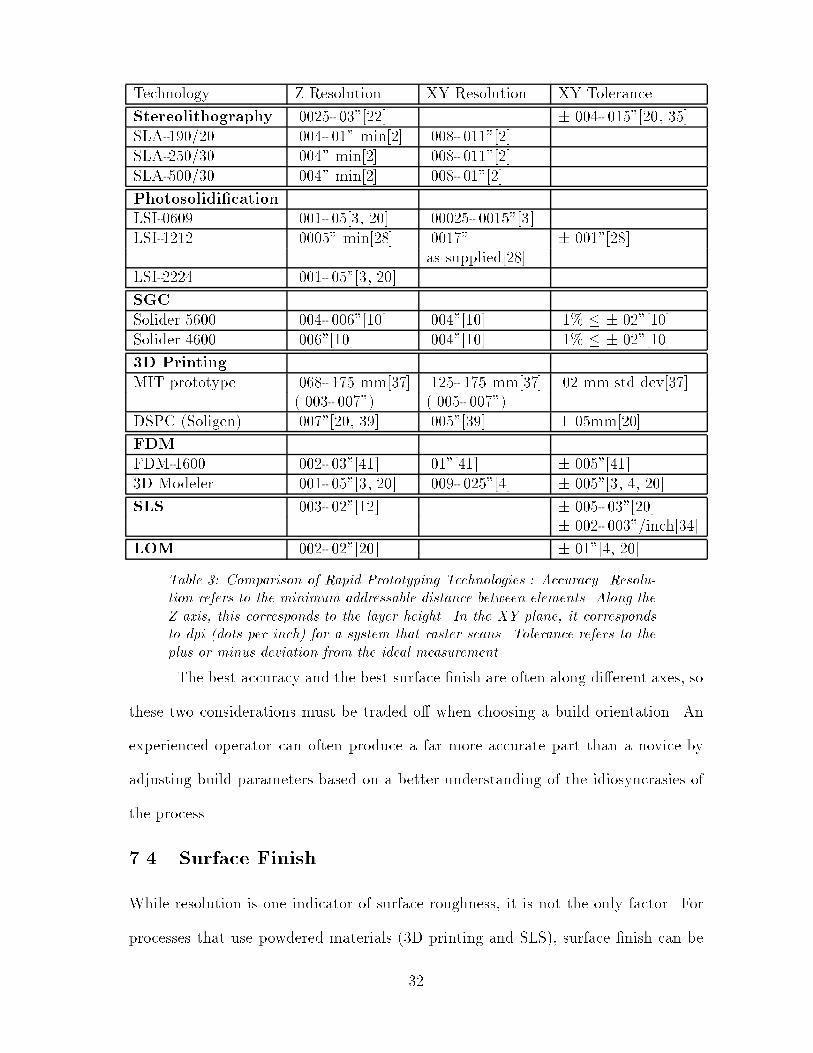
Technology Z Resolution XY Resolution XY Tolerance
Stereolithography .0025-.03"[22] �.004-.015"[20, 35]
SLA-190/20 .004-.01" min[2] .008-.011"[2]
SLA-250/30 .004" min[2] .008-.011"[2]
SLA-500/30 .004" min[2] .008-.01"[2]
Photosolidi�cation
LSI-0609 .001-.05[3, 20] .00025-.0015"[3]
LSI-1212 .0005" min[28] .0017" �.001"[28]
as supplied[28]
LSI-2224 .001-.05"[3, 20]
SGC
Solider 5600 .004-.006"[10] .004"[10] .1% � �.02"[10]
Solider 4600 .006"[10] .004"[10] .1% � �.02"[10]
3D Printing
MIT prototype .068-.175 mm[37] .125-.175 mm[37] .02 mm std dev[37]
(.003-.007") (.005-.007")
DSPC (Soligen) .007"[20, 39] .005"[39] �.05mm[20]
FDM
FDM-1600 .002-.03"[41] .01"[41] �.005"[41]
3D Modeler .001-.05"[3, 20] .009-.025"[4] �.005"[3, 4, 20]
SLS .003-.02"[12] �.005-.03"[20]
�.002-.003"/inch[34]
LOM .002-.02"[20] �.01"[4, 20]
Table 3: Comparison of Rapid Prototyping Technologies : Accuracy. Resolu-
tion refers to the minimum addressable distance between elements. Along the
Z axis, this corresponds to the layer height. In the XY plane, it corresponds
to dpi (dots per inch) for a system that raster scans. Tolerance refers to the
plus or minus deviation from the ideal measurement.
The best accuracy and the best surface �nish are often along di�erent axes, so
these two considerations must be traded o� when choosing a build orientation. An
experienced operator can often produce a far more accurate part than a novice by
adjusting build parameters based on a better understanding of the idiosyncrasies of
the process.
7.4 Surface Finish
While resolution is one indicator of surface roughness, it is not the only factor. For
processes that use powdered materials (3D printing and SLS), surface �nish can be
32
worse than the resolution alone would suggest if the powders retain their shape in the
process. Ceramic parts produced by 3D printing can be smoothed by post-dipping
them in a ceramic slurry with much smaller alumina particles, and polycarbonate
SLS parts can be epoxy coated to smooth and strengthen them, or coated with wax
for casting. Raster scanning, also used in 3D printing and SLS, leads to poor surface
�nish at the edges of each cross section. This could be improved by doing an additional
vector scan around the pro�le, as is done with SLA systems.
Any process that requires attached external support structures has the po-
tential for surface aws where they are broken o�. This problem is particularly
pronounced with FDM, which requires dense supports that could potentially be at-
tached over the entire bottom surface of the part. To alleviate this problem, the
FDM-1600 is o�ered with multiple material deposition heads and software to support
the recently developed break away support system.
7.5 Materials
Di�erent SFF technologies are compatible with a variety of materials. Stereolithog-
raphy, photosolidi�cation, and solid ground curing are all fundamentally limited to
photopolymers, with the original acrylate polymers now largely replaced by tougher
epoxies. LOM was initially available for use with paper sheets only, but can now be
used with plastics, composites, and ceramics as well. It could theoretically work with
any material available in sheets that can be glued together and cut by a laser. 3D
printing can be used with ceramics, plastics, metals, and metal-ceramic composites.
Any combination of a material that comes in a powdered form and can be consol-
idated with a liquid binder is a candidate for use. SLS has also been used with a
wide variety of materials, including nylon, investment casting wax, polycarbonate,
and metal composites. Any material that comes in powdered form and can be sin-
33

tered together by a laser is a candidate for this process. FDM has been used with
machinable and investment casting wax as well as thermoplastics. It is suitable for
materials with relatively low melting points, since it does not include a powerful laser.
Material costs for the di�erent SFF systems benchmarked by Chrysler vary
by a factor of two. Chrysler reported the lowest per-part material costs (for the
speedometer part with a 6.75 in3 envelope) of $3.08 and $3.82 for SLA and LOM
respectively, identical costs of $4.00 for SLA and FDM, and the highest material
costs of $5.96 for SGC. The photopolymers used for SLA cost from $250-700 per
gallon; those used with LightSpeed's system only cost $150 per gallon. FDM �lament
spools cost about $350 and produce a part volume roughly equal to that produced
by a gallon of photopolymer.
For most applications, the brittleness of the acrylates used in stereolithography
and related processes is a serious drawback. Research aimed at developing less brittle
resins has resulted in the introduction of a tougher epoxy resin for building SLA
prototypes. However, for one application, building exible reinforced rubber parts, a
process has been developed that relies on the brittleness of the acrylate [43]. Flexible
parts are built by applying successive layers of fabric wetted with rubber resin around
an expendable tool, resulting in a part with uniform wall thickness. Traditional
processes use a master tool and an intermediate tool to form the �nal sacri�cial tool
that the part is shaped upon. This �nal sacri�cial tool is washed away once the part
is cured. Using SLA, the �nal tool can be built directly from acrylate resins and
removed simply by crushing the cured part with one's hands. The exible part is
undamaged but the brittle tool shatters and falls away.
Many other processes use SFF parts as tools or patterns for creating sec-
ondary tooling, greatly increasing the choice of materials for the �nal part. Direct
34
shell production casting, the �rst commercial application of 3D printing, is designed
speci�cally for making ceramic molds and cores for casting. DTM uses SLS to pro-
duce sintered metal parts that are used as production tools, as well as polycarbonate
parts that are coated with wax and used as patterns for investment casting. LOM
and SLA parts can be used for RTV molding, spray metal tooling, and investment
casting. FDM parts can also be used with spray metal tooling and investment cast-
ing. SGC parts can be used with silicon rubber, epoxy, or spray metal tooling, and
coated models can be used as patterns for sand casting.
7.6 Part Geometry
Part geometry capabilities are limited by minimumpositive and negative feature size,
the build area of the system, input formats, support requirements, and by whether
material can be removed from internal voids. Table 4 presents a summary comparison
of the geometric capabilities of di�erent SFF systems.
One of the advantages of many SFF processes over traditional prototyping
is the ease of making complicated shapes with inaccessible interior chambers. The
Solider system has the fewest constraints on part geometry, since all unhardened
polymer is vacuumed up between layers, and wax fully supports the part during
building. This allows fully assembled mechanisms to be built, such as interlocking
gears. Completely enclosed voids cannot be manufactured, however; a small outlet
is needed to remove the support wax. (See Table 5 for a rating of the applicability
of di�erent technologies to a variety of challenging geometries.) Stereolithography
and photosolidi�cation can handle small internal voids if drain holes are added to the
design to allow uncured polymer to escape, but access to the interior to remove the
supports that would be required for any signi�cant overhang remains an issue. The
same is true for fused deposition manufacturing. For 3D printing, SLS, and LOM, the
35

Technology Max Area(inches) Min Feature Size Input
Stereolithography .008"[20] .STL, .SLC[2]
SLA-190/20 7.5x7.5x10[2]
SLA-250/30 10x10x10 [2]
SLA-500/30 20x20x23[2]
Photosolidi�cation .STL[20]
LSI-0609 6x6x9[3]
LSI-1212 12x8.25x12 [28]
LSI-2224 22x22x24[20]
SGC .006" horizontal, .STL, .UNV,
.024" vertical [10] VDA-FS, IGES,
.CFL, Pro/E [26]
Solider 5600 20x14x20[10]
Solider 4600 14x14x14[10]
3D Printing .007"[20]
DSPC (Soligen) 10x8x8[20] .STL
FDM .STL, IGES,
NC G-code[26]
FDM-1600 9.5x9.5x10[41] .01-.1"[41]
3D Modeler 12x12x12[3, 4] .01-.125"[20]
SLS
Sinterstation 2000 12" cylinder .015" PC, nylon; .STL, IGES[22]
x 14"[12] .03" wax[20]
LOM .01"[20] .STL[20]
LOM-1015 14.5x10x14[4, 20]
LOM-2030 32x22x20[4, 20]
Table 4: Comparison of Rapid Prototyping Technologies: Geometric Speci�cations
requirement of removing unhardened powder or tiled pieces of material from internal
voids means geometry with voids with limited access cannot be manufactured. This is
a bigger problem with LOM since more force is required to separate the tiled material
from the part.
The largest build area for a SFF system available in the U.S. is 32x22x20
inches, i.e. over 14,000 in3, found in the LOM-2030. Stereolithography, photosolidi�-
cation, and solid ground curing systems are all available in multiple sizes with a high
end machine that has a large build area of over 5,000 in3, with at least a 20x20 inch
cross section in the largest dimension. SLS, FDM, and 3D printing systems are all
36

Hollow sphere Hollow sphere Two nested, Hilbert tube Preassembled
with drain perforated octagear
Process and vent spheres mechanism
SLA F B C B C
SGC F A A A A
3DP F B A A B
FDM B B C B C
SLS F B A A B
LOM F F C B C
Table 5: Comparison of Rapid Prototyping Technologies: Predicted Part Ca-
pabilities. A grade of \A" indicates that the given technology should not have
trouble with this geometry. A grade of \B" indicates that supports that could
be di�cult to remove may be required for this geometry, or that the removal
of excess powder could be di�cult. A grade of \C" indicates that interior
supports that may be di�cult or impossible to remove are required for this ge-
ometry. A grade of \F" indicates that the given technology would not be able
to manufacture this geometry.
limited to models with smaller build areas of under 2,000 in3.
Parts that are too large to be built in one piece must be segmented into smaller
components to be assembled after building. Some SFF systems, including the Solider,
provide optional software for breaking up .STL �les of larger parts into pieces that
can be manufactured individually. Dowels can also be inserted into the part �les to
aid in assembly.
All of the commercial SFF systems accept data in the .STL format, the simple
triangulated boundary representation developed by 3D Systems for the �rst SLA ma-
chine. Cubital accepts a variety of CAD data formats for input, but converts them all
to .CFL, its own faceted representation. DTM's SLS machines accepts IGES surface
model input in addition to .STL, making it possible to describe curved surfaces ex-
actly. Stratasys's FDM machines include their own NURBS based modeling software,
which slices models into layers and converts them to NC G-code programs to con-
37

trol the material deposition. Designs can also be imported from other CAD software
packages via solid, surface, or wireframe IGES representations or .STL �les, or users
can generate their own NC programs and use these to control the machine directly.
7.7 Scalability
The scalability of an SFF technology is a consideration when evaluating its future
potential, not just its current implementation. Some technologies are more promising
than others for building larger parts than those that current systems can produce.
This is a potential advantage of ink-jet based technologies such as 3D printing, which
can be parallelized by using a multiple nozzle printhead, allowing larger, faster sys-
tems to be built. The size of systems employing lasers may be limited by the focusing
capabilities of the laser, which may restrict the maximum size that the build area can
reach before more expensive mechanical movements are needed to replace de ection
mirrors.
7.8 Environmental Considerations
Other criteria for evaluating SFF technology include energy usage, recycling, and
safety.
In theory, photopolymer based approaches can be more energy e�cient because
the crosslinking reaction that hardens the polymer is merely initiated by the laser.
The helium cadmium and argon ion UV lasers used by 3D Systems, however, are less
than .01% energy e�cient, which tends to cancel out this advantage. CO2 lasers,
used by DTM and Helisys for SLS and LOM respectively, can be approximately 12%
energy e�cient, but output wattage must be much higher to sinter and cut material
than to initiate polymerization, so the input wattage is roughly equivalent. Because of
the extreme variations in build times with the di�erent systems, energy usage should
38

be measured and compared for a part's entire build cycle.
Recyclability varies across SFF systems. With SLS, unsintered powder brushed
o� of the part is strained and reused. Entire FDM parts and supports can be ground
up and used to create partially recycled �lament [51]. In SLA systems, uncured resin
in the vat can be reused. Cubital's Solider has the disadvantage that unused resin
is still partially exposed, so it can't be recycled, and neither can the wax used for
support. The adjustable build volume helps to reduce the total volume of waste,
however. In terms of recyclability, LOM is probably the worst of the commercial
technologies because it generates so much solid waste.
SFF systems are industrial tools with industrial safety requirements. Systems
with lasers need to have enclosed housings to protect the users' eyes and skin. Many
SFF processes generate toxic fumes and require installation in ventilated environ-
ments. SLS uses nitrogen gas; DTM recommends using an oxygen monitor in the
room with their equipment to ensure that the air remains breathable in the event of
a leak. Uncured photopolymers are toxic and cause a potential toxic waste disposal
problem. One solution is to cure any waste in sunlight, creating non-toxic solid waste
instead. FDM is the best choice for safety, having none of these problems, and it is
the only one of these systems that can be installed in an o�ce environment.
8 Conclusion
Each technology has its own advantages and market niche, which is what has allowed
each of the machines' producers to survive as a viable commercial enterprise (Table
6, page 40).
Stereolithograpy SLA machines produced by 3D Systems remain the SFF mar-
ket leaders. SLA was the �rst to market, leading to a larger installed base and
39

Technology Developer
Stereolithography 3D Systems, Inc.
26081 Avenue Hall
Valencia, CA 91355
805/295-5600
fax: 805/257-1200
Photosolidi�cation Light Sculpting, Inc.
Distributor: John Webb
Results Marketing Corporation
1126 S. 70th St Suite 210A
Milwaukee, WI 53214-3151
414/475-2600
fax: 414/475-4384
Solid Ground Curing Cubital America Inc.
1307F Allen Drive
Troy, MI 48083
810/585-7880
fax: 810/585-7884
http://www.cubital.com/cubital/index.html
3D Printing Soligen Technologies, Inc.
19408 Londelius St.
Northridge, CA 91324
818/718-1221
fax: 818/718-0760
Fused Deposition Modeling Stratasys, Inc.
14950 Martin Drive
Eden Prairie, MN 55344-2020
612/937-3000
fax: 612/937-0070
Laminated Object Manufacturing Helisys
24015 Garnier St
Torrance, CA 90505
310/891-0600
Selective Laser Sintering DTM Corporation
1611 Headway Circle
Building 2
Austin, TX 78754
512/339-2922
fax: 512/832-6753
http://www.dtm-corp.com/
Table 6: Contacts
40

greater name recognition and end-user expertise. 3D Systems also has the most ma-
ture technology, with the support of outside vendors for developing better resins and
an automatic support generation program, Bridgeworks. The East Bay prototyping
companies Metalcast Engineering and Plynetics perceive that the smoothness and
accuracy of SLA parts is the highest in the industry [14].
Cubital's Solider solid ground curing systems produce more accurate parts
than SLA, but the huge size and expense of the system have doubtless worked against
its widespread acceptance. It is capable of producing the most versatile geometries,
including assembled mechanisms, with higher accuracy and without the dimensional
stability problems caused by shrinkage and warpage associated with SLA. For the
moment, however, the majority of users seem unwilling to make the additional in-
vestment to obtain these advantages.
On paper, Light Sculpting's photosolidi�cation systems look comparable to
those of 3D Systems and Cubital in every area except cost, being less than half the
price. As of 1993, however, they had shipped no units, and no independent veri�cation
of the vendor's speed and accuracy claims are available.
Selective laser sintering o�ers wider material choices than photopolymer ap-
proaches, including tougher materials, making it a better choice for producing func-
tional mechanical prototypes directly. Although its accuracy is similar to that of
SLA, the rougher surface �nish makes it less desirable for casting.
Fused deposition modeling o�ers the only open architecture and the only ma-
chine suitable for use in an o�ce environment. It produces small prototypes rapidly
and at a relatively low cost when thick layers are used. It has been less successful in
commercial prototyping environments mainly because the seam formed when moving
between layers has not been brought to within the tolerances of the rest of the process.
41

Direct shell production casting with 3D printing is the technology of choice
for producing one-shot ceramic molds for molding metal parts. Many companies will
want several copies of a prototype of the �nal part design, however, which can be
produced more economically with traditional �ve step investment casting o� of an
SLA positive, which can be hand �nished to provide a smoother �nish than can be
obtained with DSPC.
Laminated object manufacturing has much lower quality and accuracy than
the other commercial technologies, but it is capable of producing large one-shot parts
economically. It is appropriate when material properties and tight tolerances are not
an issue.
Unfortunately, shortcomings of many current CAD tools and the .STL inter-
change format prevent SFF from being used to its full potential. The majority of
CAD software systems combine solid and surface based modeling techniques to give
users maximum exibility. Such systems allow the user to create non-solid parts that
may nevertheless appear solid, often because round-o� errors cause minuscule cracks
in boundary surfaces. Such systems may not have a clear semantic distinction be-
tween the inside and outside of a model, a distinction that is necessary to produce a
valid .STL description. Since .STL stores no connectivity data, it provides no support
for veri�cation of the consistency or correctness of a model description.
An inherent de�ciency of .STL is the large size of �les. Curved surfaces can
only be represented approximately, and more accurate approximations require larger
�les. Repetitive information at the lowest level is required by de�nition, since each
vertex must appear in at least three triangular facets of a valid closed solid, and its
coordinates must be speci�ed explicitly for each facet that shares that vertex. The
inside and outside of the solid relative to each facet is speci�ed by the ordering of the
42

facet vertices as well as a surface normal. Redundant information is required, yet there
are no semantics to de�ne which information to believe if the redundant information
is inconsistent. Because .STL is non-hierarchical, patterns and relationships between
facets cannot be used to represent the model more compactly.
A simple, hierarchical, high-level language is needed for use as a digital in-
terface for SFF. Such a language should allow models to be represented compactly,
accurately, and in a device and resolution independent manner. In addition, the
same representation that was used for prototyping could then be used as the basis for
production, better integrating SFF into the development and manufacturing process.
Specialized CAD tools to support SFF are also needed, including a robust
slicing tool to create the 2.5D layers needed for process planning which will slice
realizable non-manifold objects and support adaptive layer thicknesses, a geometry
checker to verify that �les are closed solids, and rule checkers for realizable features
such as minimum separation and feature size. Additional tools could improve accu-
racy and e�ciency, such as a tool to evaluate and optimize the build orientation for
its e�ect on precision and surface �nish, and a tool to aid with part placement and
packing when building multiple parts.
With the evolution of interchange formats and of design and planning tools,
SFF has the potential to come even closer to the ideal of completely automated
fabrication of three-dimensional parts.
43

References
[1] 3D Systems, Inc. \Stereolithography Interface Speci�cation". Company litera-
ture, 1988.
[2] 3D Systems, Inc. Company literature, 1995.
[3] Steven Ashley. \Rapid Prototyping Systems". Mechanical Engineering, pages34{43, April 1991.
[4] Stacey Au and Paul K. Wright. \A Comparative Study of Rapid Prototyping
Technology". In Intelligent Concurrent Design : Fundamentals, Methodology,Modeling, and Practice, pages 73{82, New Orleans, Louisiana, November 28{
December 3, 1993. ASME Winter Annual Meeting.
[5] B.A. Beckert. \Cutting it in Rapid Prototyping". Computer-Aided Engineering,10(9):28{33, September 1991.
[6] Biomet, Inc. \Rapid Prototyping: A Strategic Tool in Concurrent Engineering".
Industrial Engineering, 24(11):22, November 1992.
[7] CAD/CAM Publishing, Inc. \IBM Uses Stereolithography to Prototype Pen-
Based Computer". Rapid Protyping Report, 13(2):1, February 1993.
[8] J. D. Cawley, P. Wei, Z.E. Liu, W. S. Newman, B. B. Mathewson, and A. H.
Heuer. \Al2O3 Ceramics Made by CAM-LEM (Computer-Aided Manufacturing
of Laminated Engineering Materials) Technology". In Solid Freeform FabricationSymposium, pages 9{16, Austin, TX, 1995.
[9] S.S. Crump. \Fused Deposition Modeling (FDM): Putting Rapid Back into Pro-
totyping". In The Second International Conference on Rapid Prototyping, pages354{357, Dayton, Ohio, June 23-26, 1991. The Rapid Prototype Development
Laboratory (RPDL).
[10] Cubital Ltd. Company Literature, 1995.
[11] Patricia Parks Denucci. \New Process Creates Prototypes{Fast". Foundry Man-agement and Technology, pages 22{24, November 1993.
[12] DTM Corporation. Company Literature, 1995.
[13] Debasish Dutta. \Layered Manufacturing in Project Maxwell". In NSF Solid
Freeform Fabrication Workshop, Pittsburgh, PA, June 5{6, 1995.
[14] Randy Erickson, MetalCast Engineering. Personal conversation, September 28,
1995.
[15] K. Hartmann et. al. \Robot-assisted Shape Deposition Manufacturing". Proceed-ings 1994 IEEE International Conference on Robotics and Automation, 4:2890{5,May 8 { 13, 1994.
44

[16] M. Feygin. \LOM System Goes Into Production". In The Second International
Conference on Rapid Prototyping, pages 347{353, Dayton, Ohio, June 23-26,
1991. The Rapid Prototype Development Laboratory (RPDL).
[17] E.V. Fudim. \Photosolidi�cation of Three-Dimensional Objects by Simultaneous
Contact Imaging of Whole Layers of Photopolymer". In The Second InternationalConference on Rapid Prototyping, pages 379{85, Dayton, Ohio, June 23-26, 1991.The Rapid Prototype Development Laboratory (RPDL).
[18] Ernie E. Guinn. \CAD/CAM and Rapid Prototyping". Technical Paper MS91-
296, SME, One SME Drive, P.O. Box 930, Dearborn, Michigan 48121, 1991.
CAD/CAM Technology for Tool and Dies, South�eld, Michigan, March 19{20,
1991.
[19] Helisys, Inc. Company literature, 1995.
[20] Lee Hornberger. \Rapid Prototyping Study". Technical report, Santa Clara
University, 1993.
[21] Charles W. Hull and Paul F. Jacobs. \Integration of Stereolithography into Agile
Manufacturing". 3D Systems Company Literature, 1993.
[22] Paul F. Jacobs. Rapid Prototyping and Manufacturing : Fundamentals of Stere-olithography. Society of Manufacturing Engineers, Dearborn, MI, 1992.
[23] Paul F. Jacobs. \Lecture Notes for Paul F. Jacobs, PhD". In Rapid Prototyping:Technologies and Applications. Univerity of California, Los Angeles, UniversityExtension, Dept. of Engineering, Information Systems, and Technical Manage-
ment, Short Course Program, January 23-25, 1994.
[24] Jerome L. Johnson. \Lecture Notes for Jerome L. Johnson". In Rapid Pro-totyping: Technologies and Applications. Univerity of California, Los Angeles,
University Extension, Dept. of Engineering, Information Systems, and Technical
Management, Short Course Program, January 23-25, 1994.
[25] Chua Chee Kai. \Three-dimensional Rapid Prototyping Technologies and Key
Development Areas". Computing & Control Engineering Journal, 5(4):200{6,August 1994.
[26] Detlef Kochan. Solid Freeform Manufacturing : Advanced Rapid Prototyping.Elsevier, Amsterdam ; New York, 1993.
[27] Suresh Konda, Ira Monarch, Philip Sargent, and Eswaran Subrahmanian.
\Shared Memory in Design: A Unifying Theme for Research and Practice".
In Research in Engineering Design: Theory, Applications, and Concurrent En-gineering, pages 23{42. Springer-Verlag New York Inc., 1992.
[28] Light Sculpting, Inc. Company literature, 1995.
45

[29] Allan J. Lightman. \Tool-Less Rapid Prototyping Technologies - An Overview".
Technical Paper 911115, SAE International, 400 Commonwealth Dr., Warren-
dale, PA 15096, 1991. 1991 SAE Aerospace Atlantic, Dayton, Ohio, April 22{26,
1991.
[30] Brian B. Mathewson, Wyatt S. Newman, Arthur H. Heuer, and James D. Cawley.
\Automated Fabrication of Ceramic Components from Tape-Cast Ceramics". In
Solid Freeform Fabrication Symposium, pages 253{260, Austin, TX, 1995.
[31] Tom Mueller. \Applications of Stereolithography in Injection Molding". In TheSecond International Conference on Rapid Prototyping, pages 323{329, Dayton,Ohio, June 23-26, 1991. The Rapid Prototype Development Laboratory (RPDL).
[32] Society of Manufacturing Engineers. Manufacturing Insights: Rapid Tooling,
Rapid Parts. Videocassette, 1994.
[33] Penton Publishing, Inc. \Manufacturing Systems (Buyers Guide)". Computer-Aided Engineering, 12(12):47{50, December 1993.
[34] Plynetics Corp. \Plynetics Selective Laser Sintering". WWW Report
(http://www.plynetics.com/sls.html), 1995.
[35] Plynetics Corp. \Plynetics Stereolithography". WWW Report
(http://www.plynetics.com/sla.html), 1995.
[36] Kendrick E. Richardson. \The Production of Wax Models by the Ballistic Parti-
cle Manufacturing Process". In Second International Conference on Rapid Pro-totyping, pages 16{22, Dayton, OH, June 23-26, 1991. The Rapid Prototype
Development Laboratory (RPDL).
[37] E. Sachs, M. Cima, J. Bredt, A. Curodeau, T. Fan, and D. Brancazio. \CAD-
Casting: Direct Fabrication of Ceramic Shells and Cores by Three Dimensional
Printing". Manufacturing Review, 5(2):117{126, June 1992.
[38] E. Sachs, P. Williams, D. Brancazio, M. Cima, and K. Kremmin. \Three Dimen-
sional Printing: Rapid Tooling and Prototypes Directly from a CAD Model". In
Proceedings of Manufacturing International '90, pages 131{136, Atlanta, GA,March 25{28, 1990.
[39] Soligen, Inc. Company Literature, 1995.
[40] Spatial Technology, Inc. ACIS Geometric Modeler: Technical Overview, version1.5 edition, September 1993.
[41] Stratasys, Inc. Company Literature, 1995.
[42] Behnam N. Tabrizi and Kathleen M. Eisenhardt. \Accelerating Product De-
velopment". Technical report, Department of Industrial Engineering, Stanford
University, March 17, 1994.
46
[43] Stan W. Thomas. \Stereolithography Simpli�es Tooling for Reinforced Rubber
Parts". Mechanical Engineering, pages 62{66, July 1992.
[44] Lee Weiss. Personal conversation, June 5, 1995.
[45] Lee Weiss, Cristina Amon, Jack Beuth, and Susan Finger. \Shape Deposi-
tion Manufacturing". Technical report, Engineering Design Research Center,
Carnegie Mellon University, 1995.
[46] Lee Weiss and Fritz Prinz. \Shape Deposition Processing". In NSF SolidFreeform Fabrication Workshop, Pittsburgh, PA, June 5{6, 1995.
[47] Terry T. Wohlers. \Advances in Prototyping". Computer Graphics World,14(12):53{58, December 1991.
[48] Terry T. Wohlers. \The Real Cost of Rapid Prototyping". Manufacturing Engi-neering, 107(5):77{79, November 1991.
[49] Terry T. Wohlers. \Chrysler Compares Rapid Prototyping Systems". Computer-Aided Engineering, 11(10):84{90, October 1992.
[50] Terry T. Wohlers. \Cashing in on Rapid Prototyping". Computer-Aided Engi-neering, 12(9):28{32, September 1993.
[51] Lamont Wood. \Rapid Automated Prototyping : An Introduction". Industrial
Press, 1993.
[52] Paul Wright. Intelligent Manufacturing Systems: Technology and Management(Course Notes). University of California at Berkeley, Berkeley, CA 94720, Fall,
1995.
47

Glossary
3D Systems Developer and producer of SLA Stereolithography systems.
ACIS A 3D boundary-representation format and geometric modeler developed by
Spatial Technology Inc.
BPM Ballistic Particle Manufacturing; an SFF technology under development at
Perception Systems.
CAD Computer Aided Design.
.CFL Cubital Facet List, a faceted but more compact input format to replace .STL
that is used as the �nal interface to Cubital's Solider machines.
Cubital Developer and producer of Solid Ground Curing (SGC) Solider systems.
DSPC Direct Shell Production Casting, the �rst commercial application of 3D Print-
ing, developed by Soligen Technologies. The systems uses modi�ed ink-jet noz-
zles to print binder onto a powder bed, producing ceramic molds for casting.
DTM Commercial licenser of Selective Laser Sintering (SLS) technology and pro-
ducer of the Sinterstation 2000.
FDM Fused Deposition Modeling; an SFF technology, used in systems produced by
Stratasys, that extrudes melted wax or plastic �lament to build up parts.
G-code The low-level programming language used to control NC machine tools.
Helisys Developer and producer of Laminated Object Manufacturing (LOM) sys-
tems.
IGES Initial Graphic Exchange Speci�cation. A non-proprietary graphics exchange
format; ANSI standard Y14.28.
Investment Casting A casting process that uses a metal tool to shape a sacri�cial
positive that is �rst coated with a ceramic shell and then burned out so that
48

metal can be cast in the ceramic mold, which in turn breaks when the metal
hardens.
Lost Wax Casting Investment casting with a wax sacri�cial positive.
LOM Laminated Object Manufacturing; a subtractive SFF technology, used in sys-
tems produced by Helisys, that builds up parts out of cross sections cut from
material supplied in sheets.
LSI Light Sculpting, Inc., developer and producer of photosolidi�cation systems.
NC Numerical Control. NC machine tools are controlled by simple G code programs.
NURBS Non-Uniform Rational B-Spline.
RPM Rubber Plaster Mold process, a form of investment casting using a soft ure-
thane tool to produce plaster molds for the �nal casting step[7].
RTV Room Temperature Vulcanizing.
SDM Shape Deposition Manufacturing, an SFF technology under development at
Carnegie Mellon University.
SGC Solid Ground Curing; a layer-at-a-time, photopolymer based SFF technology
used in systems produced by Cubital.
SFF Solid Freeform Fabrication.
SLA Stereolithography Apparatus produced by 3D Systems (and trademark of same).
.SLC New SFF exchange format developed by 3D Systems to supplement .STL.
SLS Selective Laser Sintering; an SFF technology developed at UT Austin and used
in systems produced by DTM Corporation that use lasers to fuse powdered
particles.
SME Society of Manufacturing Engineers.
Solider The Solid Ground Curing (SGC) system line sold by Cubital.
Soligen Producer of the Direct Shell Production Casting (DSPC) system, the �rst
commercial application of 3D Printing.
49

.STL The standard interchange format to specify 3D solids for SFF production.
Speci�es solids via a triangulated boundary representation.
Stratasys Developer and producer of Fused Deposition Modeling (FDM) systems.
.UNV SDRC-IDEAS (Structured Dynamics Research Corporation) \universal �le"
interchange format for 3D solids.
VDA-FS The standard CAD format used by the auto industry in Europe.
50

A Estimated Part Costs
A.1 Assumptions
In 1992, Chrysler conducted a widely quoted study of the costs of producing a pro-
totype part (a 1.5x1.5x3" speedometer adaptor part) on the di�erent SFF machines
it was considering for purchase. Chrysler already owned two SLA-250 systems that
it used to build the part itself, but in order to evaluate the other systems it sent the
.STL �le for the part to the manufacturers and asked them to build it. Helisys, DTM,
and Cubital all produced the part using beta versions of their systems; 3D Systems
and Stratasys used a production systems. Today, production versions of all of these
technologies are available. Although many of these systems are capable of producing
parts within the same range of layer thicknesses, each manufacturer chose a di�erent
layer thickness for this study, further complicating the interpretation of the results.
Using the Chrysler data on build times and operating costs, I have re-estimated
the cost of producing the part using SLA, SLS, SGC, LOM, and FDM. For these
new estimates, depreciation and maintenance costs are calculated based on di�erent
usage rates for machines that required attended operation, and the charges for build
time and materials are amortized if multiple parts could be built at the same time
without a�ecting build times and/or material costs linearly. These assumptions are
most appropriate for a service bureau or other organization that is using its rapid
prototyping equipment at near capacity, always having enough jobs to pack the build
area and keep the machine running.
Additional factors could be incorporated into the model to obtain even more
accurate estimates. No attempts have been made to include the contribution of
power requirements, facilities costs for housing the equipment and providing for a safe
operating environment (e.g. ventilation systems), or optional software or equipment.
51

For the machines that don't require attended operation (SLA, LOM, and
FDM), hourly depreciation is calculated assuming near continuous utilization, twenty
four hours a day, six days a week, consistent with Chrysler's estimate of 4000 hours of
laser use on its SLAs in each six month period. For the Cubital Solider, which requires
attended operation, and the Sinterstation, which recommends attended operation to
improve quality, hourly depreciation is calculated assuming utilization during sixteen
hours (two shifts) a day, �ve days a week.
For SGC, the time to harden each layer and the amount of resin used for each
layer is independent of the layer geometry. Thus, both build time and material costs
could be amortized over the �fty eight identical speedometer parts that �t into a
single layer in the build volume. However, the Chrysler reports of material costs for
a single part are inaccurate, so new estimates of the material costs are used. Cubital
systems use resin that costs $276/gallon, and all the resin in the machine must be
disposed of even if it is not hardened. Even if the build volume could be reduced to
exactly the envelope of the speedometer part, this would still be $8 worth of resin,
more that the $5.96 reported. But since only the width and height of the build
volume can be adjusted, a build volume of 1.5x1.5x14" would have to be �lled with
resin, at a cost of almost $38 for the single part. To �ll the entire build volume to
a height of 1.5" would require $500 worth of resin. Since the Solider begins building
as soon as the �rst layer is sliced [49], preprocessing time would not increase linearly
when multiple copies of the same part are produced. Total preprocessing time for
a multiple part build is estimated at three hours, the upper limit Cubital advertises
[10], approximately nine times the preprocessing time for a single speedometer part.
Preprocessing times for SLA and SLS were adjusted by a similar factor of 15% of the
number of parts.
52

Since SLA systems use point-by-point solidi�cation, the rasterization portion
of the build time would increase roughly linearly with the number of parts, but the
resin spreading and recoating portions of the build time can be amortized over the
number of parts that �t in a layer. For the SLA-250, this is eighteen speedome-
ter parts, and for the SLA-500, seventy two parts. The build parameters were not
speci�ed in the Chrysler study, but if default parameters for the recoating values
are assumed (30 seconds leveling time, 5 second sweep, 4 second post-dip delay, .2
turns/second elevator velocity), there would be a total of approximately forty seconds
before rasterizing each layer [22]. For .01" layers, the 1.5" high part would require 150
layers not including support structures, or one hour forty minutes of recoating time,
a signi�cant fraction of the total build time. If the rest of the process was completely
linear in area, this would be a total build time of about sixty hours for the eighteen
parts for the SLA-250. Based on estimates in [24], however, the total build time for
150 layers would be no more than �fteen hours. Costs are given for both of these
estimates.
Similarly, selective laser sintering builds parts point-by-point, but multiple
parts can be built at once without a�ecting the time to deposit and level each new
layer of powder. Approximately nineteen speedometer parts �t into the Sinterstation's
build area. For SLS, the costs of attended operation and nitrogen gas usage, as
well as machine depreciation, can be amortized over the multiple parts produced.
The Sinterstation was run with .005" layers for the Chrysler benchmark, requiring
300 layers to be deposited and leveled, for the fastest per-layer speed of thirty six
seconds. If �fteen seconds of this time was spent preparing the powder bed and the
rasterization time was linear with area, then the time for nineteen parts would be
about thirty �ve hours. Again, Johnson's estimates [24] predict a shorter build time,
53

six hours, so this whole range is considered. Preprocessing time is amortized using
the same factor as for the Solider, since slicing occurs during the build. Alternate
calculations based on running the Sinterstation unattended were also run.
No amortization was applied to the Helisys LOM �gures because this system
could only build one part at a time [49]. With modi�ed software, however, LOM
could theoretically build as many parts as �t in its build volume without increasing
build time signi�cantly. The time to slice the additional parts and cut their pro�les
would be o�set by the time savings of the reduced area to be tiled.
For FDM, the material is applied and shaped in a single point-by-point oper-
ation, so there is no advantage in building multiple parts in the same layer. There
is, however, a large speed and cost advantage to building parts with thicker layers
with FDM that is not always realizable with systems that use lasers to solidify a part.
With SLA, the laser scan speed must be decreased to compensate for the increased
thickness, allowing the laser time to penetrate more deeply. In fact, for SLA systems,
increasing the layer thickness above .005-.01" actually increases the total build time.
The two sets of �gures for FDM re ect the di�ering preprocessing and build times
Chrysler obtained with FDM, presumably for di�erent slice thicknesses. The lower
�gures are for a slice thickness of .2 inches. Of course, these parts will not be as
smooth or accurate as parts built with thinner layers.
A.2 Estimates and Sensitivity Analysis
The estimated costs for building speedometer parts based on these assumptions are
presented in Table 7. Hourly equipment depreciation was calculated based on esti-
mated usage and assuming �ve year straight line depreciation with no scrap value.
All of these cost estimates are based on the system costs and capabilities available in
1992. Today, the cost of SLS and SGC equipment has dropped, and the cost of SLA
54

and LOM has risen.
For the SGC system, the cost of attended operation and depreciation dominate
for the single part estimates; the cost of postprocessing dominates for the multiple part
estimates. For making a single small part, SGC is the most expensive solution. For
making multiple closely packed small parts, however, SGC is the cheapest solution.
In the case of multiple parts, SLA is probably the closest rival to Cubital. Unattended
SLS has comparable cost to SLA, but the parts would presumably su�er in quality.
SGC parts will be cheapest mainly because their postprocessing is faster. There are
no supports to remove and no powder that has to be laboriously brushed o�; the wax
can be removed completely automatically.
For FDM, the preprocessing costs dominate, leading to an extremely expensive
part if the layers are thin. Over 85% of the cost of the FDM part is preprocessing
cost, suggesting that with improved software this could be the cheapest technology
of all.
For LOM, preprocessing costs again dominate, though the total preprocessing
time is much closer to that of systems with faster preprocessing and hence probably
has less room for improvement than FDM. For a single small part, LOM is the
cheapest technology, and it would probably remain the cheapest for a single part
with a large cross section.
55

SLA250 SLA500 SGC SLSa SLSb FDMa FDMb LOM
'92 Equipment cost $195K $395K $490K $397K $397K $182K $182K $95K
Maintenance cost $36K $85K $49K $68K $68K $7K $7K $17K
Attendant $/hr 0 0 $22 $22 0 0 0 0
Slice thickness .01" .01" .004" .005" .005" .02" <.02" .009"
Operating hours 7488 7488 4160 4160 7488 7488 7488 7488
Depreciation $/hr $5.21 $10.55 $23.56 $19.09 $10.60 $4.86 $4.86 $2.54
Maintenance $/hr $4.81 $11.35 $11.78 $16.35 $9.08 $.93 $.93 $2.27
single part:
Machine build time 5:06 4:44 10:00 3:00 3:00 2:10 8:00 9:51
Preprocessing time :34 :34 :21 :55 :55 2:05 4:20 :46
Postprocessing time 1:45 1:45 1:00 1:20 1:20 :15 :15 :25
Preprocessing cost $37.80 $37.80 $23.50 $61.14 $61.14 $138.96 $289.00 $51.14
Postprocessing cost $38.50 $38.50 $22.00 $29.33 $29.33 $5.50 $5.50 $9.17
Materials cost $4.00 $4.00 $38.00 $5.89 $5.89 $4.00 $4.00 $3.82
Attendant cost $0 $0 $220.00 $66.00 $0 $0 $0 $0
Depreciation $26.54 $49.94 $235.58 $57.26 $31.81 $10.53 $38.89 $24.99
Maintenance $24.52 $53.73 $117.79 $49.04 $27.24 $2.03 $7.48 $22.36
Single part cost $131.38 $183.96 $656.71 $268.67 $155.42 $161.02 $344.90 $111.48
multiple parts:
Total parts 18 72 58 19 19 1 1 1
Machine build time 15{60:00 20{80:00 10:00 6-35:00 6-35:00
Preprocessing time 1:30 6:07 3:00 2:36 2:36
per part:
Preprocessing cost $5.67 $5.67 $3.45 $9.17 $9.17
Postprocessing cost $38.50 $38.50 $22.00 $29.33 $29.33
Materials cost $4.00 $4.00 $8.65 $3.38{ $3.38{
5.05 5.05
Attendant cost $0 $0 $3.79 $6.95{ $0
46.32
Depreciation $4.34{ $2.93{ $4.06 $6.03{ $3.35{
17.36 11.72 40.18 22.32
Maintenance $4.01{ $3.15{ $2.03 $5.16{ $2.87{
16.03 12.61 30.11 16.73
Per part cost $56.52{ $54.25{ $43.99 $60.02{ $48.10{ $161.02 $344.90 $111.48
81.56 72.50 149.11 79.57
Table 7: Estimated Costs of Producing Chrysler Speedometer Test Part. The
SGC part was run on a Solider 5600, the SLS part on a Sinterstation 2000,
the FDM part on a 3D Modeler, and the LOM part on an LOM-1015. The
two columns for SLS represent estimates for attended and unattended opera-
tion. The two columns for FDM are builds run with di�erent layer heights.
Labor costs are taken from the Chrysler estimates: $22/hr for attended opera-
tion and postprocessing, $51.12/hr combined rate for preprocessing labor, and
$15.58/hr computer and networking costs during preprocessing.
56