solar-assisted heat pump and energy storage for domestic heating in turkey
TRANSCRIPT

Energy Cowers. Mgmt Vol. 34, No. 5, pp. 335-346, 1993 0196-8904/93 $6.00+0.00 printed in Great Britain. All rights reserved Copyright © 1993 Pergamon Press Ltd
SOLAR-ASSISTED HEAT PUMP AND ENERGY STORAGE FOR DOMESTIC HEATING IN TURKEY
K A M I L K A Y G U S U Z , l N U R B A Y G t ' I L T E K | N 1 a n d T E O M A N A Y H A N 2
~Department of Chemistry and 2Department of Mechanical Engineering, Karadeniz Technical University, 61080-Trabzon, Turkey
(Received 6 February 1992; received for publication I 1 September 1992)
Abstract--In order to improve the performance of the solar-assisted heat pump system with energy storage for domestic heating in the Black Sea region of Turkey, an experimental set-up was constructed. In this study, the solar-assisted series heat pump system with storage and parallel heat pump system with storage are experimentally investigated and compared. This experimental apparatus consists of 30 m 2 of fiat-plate solar collectors, a laboratory with 75 m 2 floor area for heating purposes, a latent heat thermal energy storage tank that is filled by 1500 kg of encapsulated phase-change material (PCM), a heat pump with double evaporators (air- and water-sourced) and one condenser, a water circulating pump and other measuring equipment. The experimental results are obtained in December, January, February, March, April and May in the heating season of 1991 for the two heat pump systems used. The experimentally obtained results are used to calculate the collector efficiency, heat pump coefficient of performance (COP), system COP, storage efficiency and total energy consumption of the system during the heating season. The mean values of the collector efficiency, heat pump COP, system COP and storage efficiency were around to be 70, 4.2, 4.0, and 60%, respectively.
Solar energy Heat pump Energy storage Phase-change material Heat of fusion
N O M E N C L A T U R E
Ac--Solar collector area (m 2) As = Area of collector absorber (m 2)
Cpa = Specific heat of air (kJ/kg °C) Cpw = Specific heat of water (kJ/kg °C)
I ffi Incident solar insolation (W/m 2) = Collector thermal loss coefficient (V~/m 2 K)
( ~ ) ~ = Effective absorptance of cover-absorber assembly F R = Heat removal factor n~om = Collector efficiency mw= Mass flow rate of water in system (kg/h)
m ~ = Mass flow rate of air in heat exchanger (kg/s) m~ = Mass flow rate of air in condenser (kg/h)
O~oD = Heat extracted by condenser (k J/h) COP = Heat pump coefficient of performance
Wcomp = Work input to compressor (k J/h) Wpmap ffi Work input to water circulating pump (k J/h)
W~t = Work input to compressor fan (k J/h) W~ = Work input to heat-exchanger fan (k J/h) W~ = Work input to evaporator fan (kJ/h)
Tw = Water inlet temperature (K) Texl = Inlet air temperature of heat exchanger (K) T ~ = Outlet air temperature of heat exchanger (K) Tf~n -- Collector fluid (water) inlet temperature (K)
Tf.ou, = Collector fluid (water) outlet temperature (K) T ~ = Inlet water temperature of water-to-air heat exchanger To~ = Outlet water temperature of water-to-air heat exchanger
Ti~, = Inlet water temperature of store (K) To~ -- Outlet water temperature of store (K) T~n = Inlet refrigerant temperature of chiller (evaporator) T ~ - Outlet refrigerant temperature of chiller (K)
T~o~l = Inlet air temperature of condenser (K) T~o~2 = Outlet air temperature of condenser (K) T~ool ----Inlet refrigerant temperature of condenser (K) T~o~2 ffi Outlet refrigerant temperature of condenser (K) T ~ = Inlet refrigerant temperature of air-sourced evaporator Trey2 ~ Outlet refrigerant temperature of air-sourced evaporator
335

336 KAYGUSUZ e t al.: SOLAR HEATING IN TURKEY
Tin d = Indoor air temperature (K) Ta = Ambient air temperature (K) A = Floor area (m 2) U = Overall thermal loss coefficient (kWh/m 2 °C-day)
(DD)= = Number of degree-days per month ND = Number of days in a month Qd.sh = Average daily space heating load (kW)
I N T R O D U C T I O N
Solar energy is a natural resource of energy that can be collected and applied to many energy needs. It is readily converted to thermal energy (heat) that is useful for such needs as water heating, building heating, industrial process heating, drying and many others. The sun provides an abundant, clean and safe source of energy. The annual insolation to the Earth's surface amounts to 1.7 E-18 kWh. In comparison, the present yield in energy gained by fossil fuels and water power amounts to about 7.0 E-13 kWh. However, effective utilization of solar energy presently poses problems, primarily because of inefficient collection, conversion and storage [I-4].
Energy storage can reduce the time or rate mismatch between energy supply and energy demand, thereby playing a vital role in energy conservation. In processes which are wasteful of energy, energy storage will result in a saving of premium fuels. Energy storage can also improve system performance and increase reliability.
Thermal energy storage can be accomplished in two main ways: by means of sensible heat or by means of latent heat. Sensible heat utilizes the heat capacity factor. Latent heat involves the use of a phase-change material (PCM). The heat is absorbed during the melting of the PCM and retrieved during the solidification of the PCM at (nearly) constant temperature. The temperature at which the phase change occurs is one of the criteria for PCM selection because it must be compatible with the temperature range of the solar system in which the storage unit is to be integrated. Several studies have been devoted to the thermo-physical properties and problems associated with the physico-chemical behaviour of the PCM [5-8].
In order to improve the heat pump COP and displace the fossil energy resource, the idea of combining the heat pump and solar energy in mutually benefical ways has been proposed and developed in several previous studies [9-12]. On the other hand, conventional vapour compression, heating only heat pumps are not at present an economic alternative to gas-fired heating systems due to their high capital cost and the degradation in their steady-state efficiency caused by on-off cycling, supplementary electric resistance heating and frosting and defrosting losses.
One way of increasing the economic competitiveness and improving the COP of the heat pump is by combining the heat pump and thermal energy storage systems. The main effects of this combination are as follows:
(1) The thermal store allows a reduction in the required heat pump size for a given heating load. This reduces the capital cost of the heat pump, and indigenous design and mass production may lead to an integrated system at a lower capital cost than the cost of a heat pump designed to satisfy the same space heating and domestic hot water load.
(2) The store reduces the on-off cycling losses of the system because a smaller-size heat pump will run for larger periods at maximum capacity between cycles to satisfy a given heating load.
(3) The store allows the heat pump to operate at lower condensing temperatures leading to a higher steady-state COP.
(4) The store allows the heat pump to operate at night and on cloudy days in which times or periods there is no solar radiation.
In the present work, an experimental set-up was constructed to determine the dynamics of the heat pump, collectors and energy storage tank that is filled by the PCM, as used for domestic heating. The effects of various system parameters on the response of indoor air temperatures of the heating medium and water temperatures in the store and collectors at this solar-assisted heat pump system are investigated. Also, the collector efficiencies, heat pump COP, system COP, storage efficiency and total heat losses of the system during the heating season are calculated and compared.
KAYGUSUZ e t al.: SOLAR HEATING IN TURKEY 337
Table 1. Climatic conditions of Trabzon in heating season Average outdoor temperature: Minimum outdoor temperature (February): Average minimum outdoor temperature: Maximum outdoor temperature (May): Average maximum outdoor temperature: Average relative humidity: Average wind velocity Average solar insolation
9.35oc - 3.4°C
2.3oc 29.1oc 22.91oc 74.85% 2.5 m/s 5.1 MJ/m 2 day
DESCRIPTION OF THE EXPERIMENTAL SET-UP
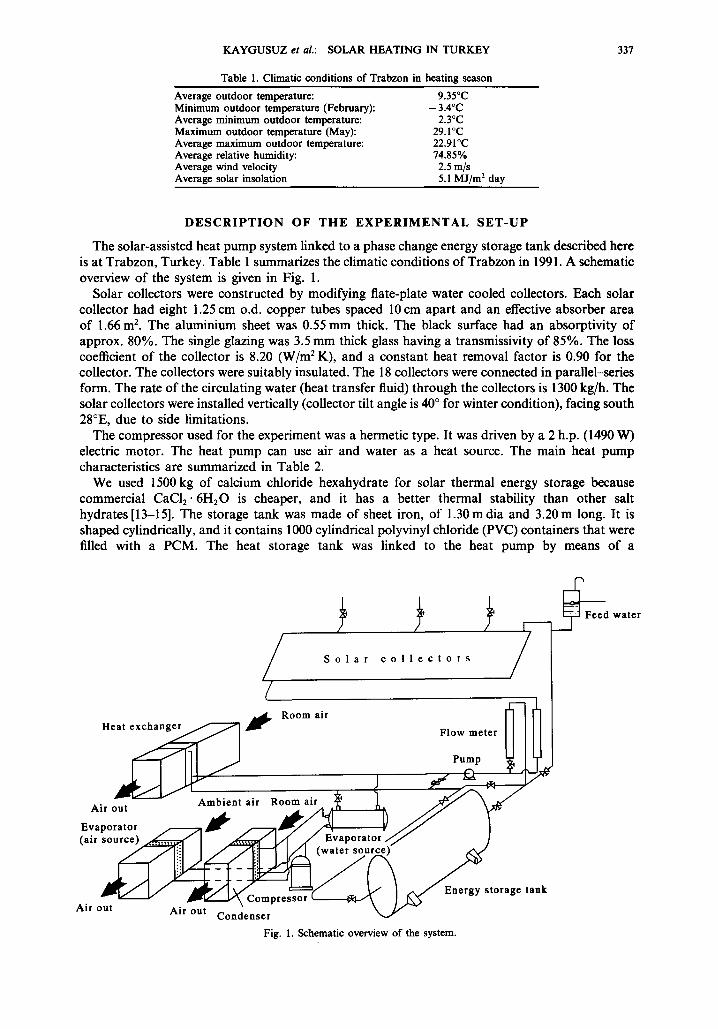
The solar-assisted heat pump system linked to a phase change energy storage tank described here is at Trabzon, Turkey. Table 1 summarizes the climatic conditions of Trabzon in 1991. A schematic overview of the system is given in Fig. 1.
Solar collectors were constructed by modifying flate-plate water cooled collectors. Each solar collector had eight 1.25 cm o.d. copper tubes spaced 10 cm apart and an effective absorber area of 1.66 m 2. The aluminium sheet was 0.55 ram thick. The black surface had an absorptivity of approx. 80%. The single glazing was 3.5 mm thick glass having a transmissivity of 85%. The loss coefficient of the collector is 8.20 (W/m 2 K), and a constant heat removal factor is 0.90 for the collector. The collectors were suitably insulated. The 18 collectors were connected in parallel-series form. The rate of the circulating water (heat transfer fluid) through the collectors is 1300 kg/h. The solar collectors were installed vertically (collector tilt angle is 40 ° for winter condition), facing south 28°E, due to side limitations.
The compressor used for the experiment was a hermetic type. It was driven by a 2 h.p. (1490 W) electric motor. The heat pump can use air and water as a heat source. The main heat pump characteristics are summarized in Table 2.
We used 1500 kg of calcium chloride hexahydrate for solar thermal energy storage because commercial CaC12" 6H:O is cheaper, and it has a better thermal stability than other salt hydrates [13-15]. The storage tank was made of sheet iron, of 1.30m dia and 3.20 m long. It is shaped cylindrically, and it contains 1000 cylindrical polyvinyl chloride (PVC) containers that were filled with a PCM. The heat storage tank was linked to the heat pump by means of a
/ /~ /~ /~ J F e e d w a t e r
'1 S o l a r c o l l e c t o r s /
/ ~ , ~ Room air ~ F~
Heat e x ~ ~F'~ FIowmeter [I I l l [
~ _ ~ Pump ~ ] ~.J
Airout Ambientair Roomair ~ t ~ ~
Evaporator /~-.........~ ~ /-------~ ~ / ~ i J J I (air source) ~ [ ~ L~ ~ Evaporator// ]
/ / - - - -7] :. .:1 I / /1"..:3'---'1 I/_1 (water source)
~ - - ' ~ ~ - - - ~ ~ _ ~ A E ~ n e r g y s t o r a g e tank Air o~t ~ ~ Air o'~u~-~C \endear] press°r ' ~ ¢ - / ~
Fig. I. Schematic overview of the system.

338 KAYGUSUZ et aL: SOLAR HEATING IN TURKEY
Table 2. Main heat pump characteristics Mark (firm): Model: Nominal voltage: Capacity rating: Power consumption:
evaporating temperature: condensing temperature: suction-gas temperature: liquid-sub-cooling: ambient temp., air-over: R-22 50 Hz
Displacement 2900 rpm: Oil charge: Refrigerant charge: Maximum working pressure: 25 bar Net weight:
DWM COPELAND DCRD 1-0200 220-240/1/50 5820 W (at following conditions) 2.07 kW (at following conditions) 7.2°C
54.4°C 35.0°C 8.3K
35.0°C
7.16 m3/h 1.5 liter 2.7 kg (recommended maximum)
28 kg
water-to-refrigerant heat exchanger for use as a heat source. The heat storage tank was insulated entirely with 60 nun thick glass wool.
In our experiments, the pressures, temperature and flow rates of the water and air were measured. Also, the ambient air and indoor air temperatures and incident solar insolation were measured. Temperatures were measured with iron--constantan thermocouples. Pressures were measured with a manometer. A Kipp-Zonen solarimeter, mounted on the vertical plane of the solar collectors (at the inclination angle), was used to measure the solar insolation. The water flow-rate was measured by means of two flowmeters. The power consumption of the system was measured with the wattmeter.
For the heating purpose, we used a laboratory building of 75 m 2 floor area. The structural properties of the laboratory building are given in Table 3.
O P E R A T I O N M O D E S
In general, solar-assisted heat pumps can work in three forms. The three combined systems are the series system in which the solar thermal energy storage is used as the source for the heat pump, the parallel system in which ambient air is used as the source for the heat pump, and the dual source system in which the storage or ambient air is used as the source, depending on which source yields the lowest work input. We have designed our experimental set-up to form dual sources for the heat pump. Because of this, the system can be used in three forms: series, parallel or dual source system. This process can be accomplished by changing the heat sources for the heat pump. The heat pump system has five operation modes:
- - m o d e 1, series system (with storage) - - m o d e 2, parallel system (with storage) - - m o d e 3, dual system (with storage) - - m o d e 4, dual system (nonstorage) - - m o d e 5, series system (nonstorage).
We have analysed only modes 1, 2 and 3 during the experiments in December, January, February, March, April and May on different days for the heating season in 1990-1991. The experiments were repeated may times, but in this paper, only some results have been presented from typical
Table 3. Construction properties of the laboratory building Window area (single glass, U = 4.8 W/m 2 °C-day): 75 m 2 Wall area (single brick, U ~ 1.6 W/m 2 °C-day): 60 m 2 Floor area (concrete, U = 2.5 W/m 2 °C-day): 75 m 2 Ceiling area (concrete + flat metal, U ffi 2.0 W/m2-day: 75 m 2 Effective UA (kWh/°C-day): 0.800 Comfort temperature: 22°C Average degree days for heating season: 2500 Average total heating load in heating season (kWh): 19,500
KAYGUSUZ etal.: SOLAR HEATING IN TURKEY 339
age•[ im
st°rk i i tan Evaporator
Pump I .
Room air
Fig. 2. Solar-assisted series heat pump system with storage.
experimental days (at clear sky conditions) for each month. More detailed description of the systems is given below:
Solar-assisted heat pump system with storage
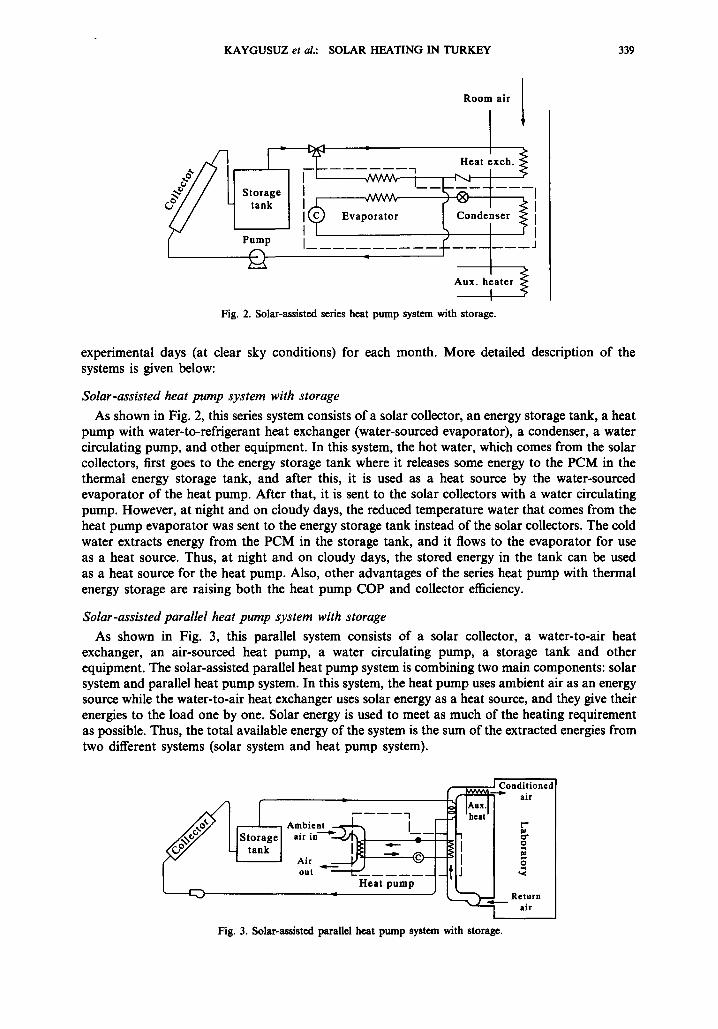
As shown in Fig. 2, this series system consists of a solar collector, an energy storage tank, a heat pump with water-to-refrigerant heat exchanger (water-sourced evaporator), a condenser, a water circulating pump, and other equipment. In this system, the hot water, which comes from the solar collectors, first goes to the energy storage tank where it releases some energy to the PCM in the thermal energy storage tank, and after this, it is used as a heat source by the water-sourced evaporator of the heat pump. After that, it is sent to the solar collectors with a water circulating pump. However, at night and on cloudy days, the reduced temperature water that comes from the heat pump evaporator was sent to the energy storage tank instead of the solar collectors. The cold water extracts energy from the PCM in the storage tank, and it flows to the evaporator for use as a heat source. Thus, at night and on cloudy days, the stored energy in the tank can be used as a heat source for the heat pump. Also, other advantages of the series heat pump with thermal energy storage are raising both the heat pump COP and collector efficiency.
Solar-assisted parallel heat pump system with storage
As shown in Fig. 3, this parallel system consists of a solar collector, a water-to-air heat exchanger, an air-sourced heat pump, a water circulating pump, a storage tank and other equipment. The solar-assisted parallel heat pump system is combining two main components: solar system and parallel heat pump system. In this system, the heat pump uses ambient air as an energy source while the water-to-air heat exchanger uses solar energy as a heat source, and they give their energies to the load one by one. Solar energy is used to meet as much of the heating requirement as possible. Thus, the total available energy of the system is the sum of the extracted energies from two different systems (solar system and heat pump system).
IL I Ambient ~ I r
nir i C ' * ~ l . . - - - I - ~
o u t I . . . . . 4- . Heat pump J
I Conditioned -"~ air
I"1 ~ r
I Fig. 3. Solar-assisted parallel heat pump system with storage.
Return air
0 KAYGUSUZ e t al.: SOLAR HEATING IN TURKEY
T T
Room air
Aux. ~ ]
-I - ' Heat e x c h a n g e r Ambient
air in
--*)8
~ i r out
Water circulating pump
~) Conditioned air
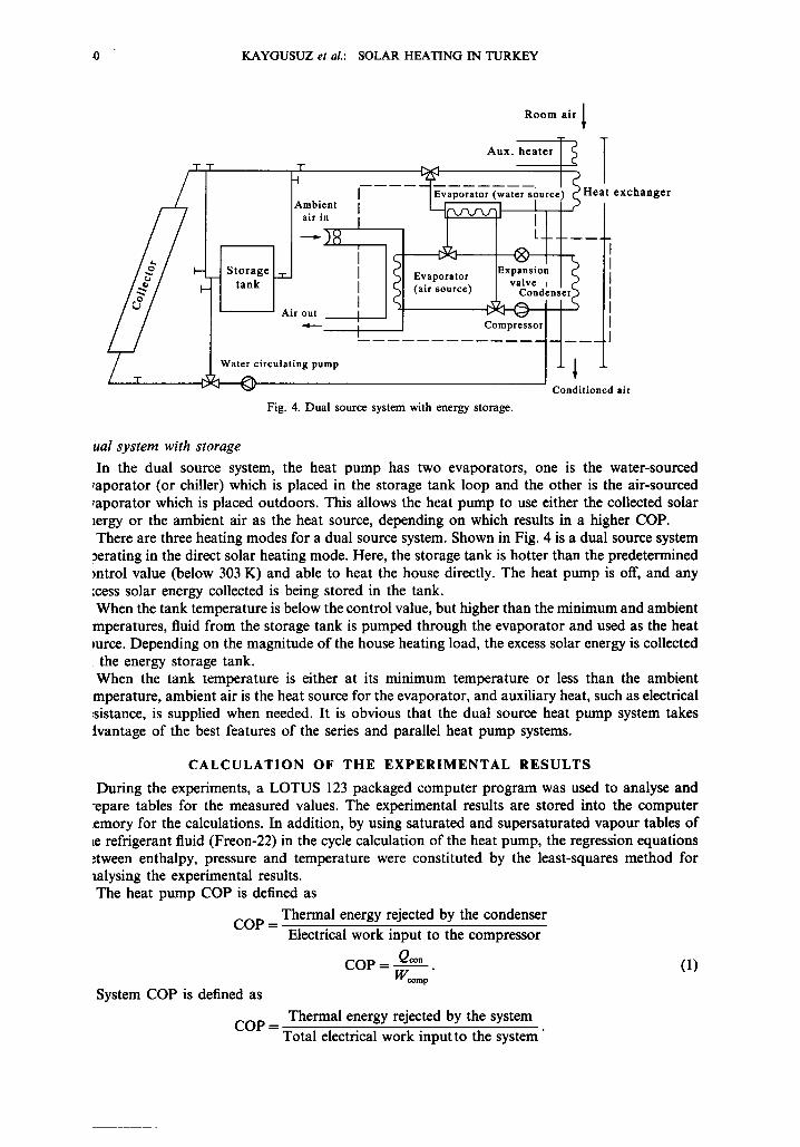
Fig. 4. Dual source system with energy storage.
ual system with storage
In the dual source system, the heat pump has two evaporators, one is the water-sourced ,aporator (or chiller) which is placed in the storage tank loop and the other is the air-sourced ,aporator which is placed outdoors. This allows the heat pump to use either the collected solar lergy or the ambient air as the heat source, depending on which results in a higher COP. There are three heating modes for a dual source system. Shown in Fig. 4 is a dual source system ~erating in the direct solar heating mode. Here, the storage tank is hotter than the predetermined mtrol value (below 303 K) and able to heat the house directly. The heat pump is off, and any :cess solar energy collected is being stored in the tank. When the tank temperature is below the control value, but higher than the minimum and ambient mperatures, fluid from the storage tank is pumped through the evaporator and used as the heat mrce. Depending on the magnitude of the house heating load, the excess solar energy is collected the energy storage tank. When the tank temperature is either at its minimum temperature or less than the ambient mperature, ambient air is the heat source for the evaporator, and auxiliary heat, such as electrical :sistance, is supplied when needed. It is obvious that the dual source heat pump system takes tvantage of the best features of the series and parallel heat pump systems.
CALCULATION OF THE EXPERIMENTAL RESULTS
During the experiments, a LOTUS 123 packaged computer program was used to analyse and :epare tables for the measured values. The experimental results are stored into the computer emory for the calculations. In addition, by using saturated and supersaturated vapour tables of Le refrigerant fluid (Freon-22) in the cycle calculation of the heat pump, the regression equations ~tween enthalpy, pressure and temperature were constituted by the least-squares method for lalysing the experimental results. The heat pump COP is defined as
Thermal energy rejected by the condenser COP =
Electrical work input to the compressor
COP-- Qcon (1) Wcomp "
System COP is defined as
COP = Thermal energy rejected by the system
Total electrical work input to the system"
KAYGUSUZ et al.: SOLAR HEATING IN TURKEY 341
The COP of the solar assisted heat pump with storage can be calculated by using following equation,
COP = m~Cpa(T~o.2 -- T~onm) ~Vcorn p --[- l/Vpum p + We f (2)
The COP of the solar-assisted parallel heat pump system with storage is defined as
COP = ma¢Cp~(r~c°"2 -- T~o. , ) + maexCpa(Tex2 -- Texl) (3)
Weomp -~- Wpump + Wcf .-~ Wex f "3!- Wev f
Instantaneous collector efficiency is given by [2],
/'/col ~--- FR (Zt~)eft A c I " (4)
Also, the net collector efficiency is defined as,
Useful energy collected
nco, = Energy incident in the plane of the collector
mw Cpw ( Tr, in - Tr.o.t) rico, = (5)
AcI
Heat pump performance data
The actual performance data obtained from the experimental results are used to generate third order polynomials relating heat pump COP to the source temperature (T). For the dual source heat pump (water and air-to-air), two different sets of polynomials are used, one set relating to the water source and the other to the air source.
For the water source heat pump:
COPH = 5.46 + 5.53 E-02 Tw - 5.33 E-04 T~: + 1.20 E-06 T,?, 3.
For the air source heat pump:
COPH = -27 .86 + 0.121Ta + 1.601 E-04Ta 2 - 7.035 E-07 T a 3.
Heat ing load calculation
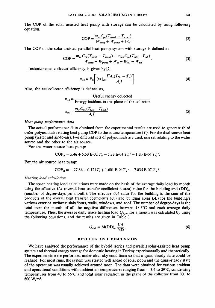
The space heating load calculations were made on the basis of the average daily load by month using the effective UA (overall heat-transfer coefficient x area) value for the building and (DD)m (number of degree-days per month). The effective UA value for the building is the sum of the products of the overall heat transfer coefficients (Ut) and building areas (At) for the building's various exterior surfaces: slab(floor), walls, windows, and roof. The number of degree-days is the total over the month of all the negative differences between 18.3°C and each average daily temperature. Thus, the average daily space heating load Qd.~h, for a month was calculated by using the following equations, and the results are given in Table 3.
UA Qd,sh = 24(DD)m ND" (6)
R E S U L T S AND D I S C U S S I O N
We have analysed the performance of the hybrid (series and parallel) solar-assisted heat pump system and thermal energy storage for domestic heating in Turkey experimentally and theoretically. The experiments were performed under clear sky conditions so that a quasi-steady state could be realized. For most runs, the system was started well ahead of solar noon and the quasi-steady state of the operation was usually achieved around noon. The data were obtained for various ambient and operational conditions with ambient air temperatures ranging from - 3.4 to 29°C, condensing temperatures from 40 to 55°C and total solar radiation in the plane of the collector from 300 to 800 W/m ~.
342 K A Y G U S U Z e t al.: SOLAR H E A T I N G IN T U R K E Y
330
M 310
~ 300
1
_ . ,"~*° ; ° ° . ~ ° 320 o / • o-o • \
, . e / e : 3 ~ ° ~ l I - .O ~ O. 0 _.... O.O ~ O. O,........ O\ 8%,
/ e o \ o%,~
2.. .- .- ' -" '- '"- '" • o~'° '° 5 °'~--'41~o
290 o.~o~O.O__O.o~O.O~O.O.,.,..o.o~o.o~ooO~o.o~o.o
280 I [ I L 10 12 14 16 18
Time o f day Fig. 5. Variation of temperature with time of day. l--Tf,out;
2--T~w~G 3--Tf, in; 4--Tind; 5--T~.
330 --
1
320 - / o / • . x.
310 e . o " ° - - 2 ° ' e - O ' . °e'"e~e."~'ex.
• / " ~ 3 ~ o e ~ o f . . ".- . .__. , \ %-..
o 300 S / ° 4 o ~ o N
n . / . _ _ o - f - ' - " o "" ": ."x
290 ~ : i ~ o "° 6 o ~ o - ~ ' ~ \ • , L ; ~ , - o - - , . , - - ' " ~ , - , - - 0 . , ~ , : ~ . ~ 0
" ~ 0 : o
280 I I I I I 10 12 14 16 18
Time o f day Fig. 6. Variation of temperature with time of day. 1--T~,,;
2--Tow G 3--T,~f2; 4~-T~n ; 5--Ti.a; 6----T~.
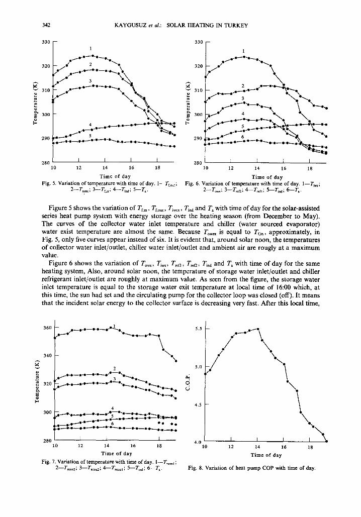
Figure 5 shows the variation of Tr,,n, Tf, om, Ti . . . . Ti.d and Ta with time of day for the solar-assisted series heat pump system with energy storage over the heating season (from December to May). The curves of the collector water inlet temperature and chiller (water sourced evaporator) water exist temperature are almost the same. Because Towex is equal to Tr, i,, approximately, in Fig. 5, only five curves appear instead of six. It is evident that, around solar noon, the temperatures of collector water inlet/outlet, chiller water inlet/outlet and ambient air are rougly at a maximum value.
Figure 6 shows the variation of Tows, Tiws, Tren, Tr~r2, T~.d and Ta with time of day for the same heating system, Also, around solar noon, the temperature of storage water inlet/outlet and chiller refrigerant inlet/outlet are roughly at maximum value. As seen from the figure, the storage water inlet temperature is equal to the storage water exit temperature at local time of 16:00 which, at this time, the sun had set and the circulating pump for the collector loop was closed (off). It means that the incident solar energy to the collector surface is decreasing very fast. After this local time,
.~ 320
o [-
_ o 1 360 , , o ~ o - o - - o - o ~ o " '~"o ,O ~ O ~O"~.-. O. O ~ ooO~... 0
\ 340 ° / %
2
.e 3 e'e ~ o . o ~ o . o ~ o . o ~ o - o ~ o . o ~ °.o....... "
,O ~ 0 . O O~
0 ~ 0 ~ 0 ~ 0
4 300 ~..._o.o~. o~o.o__o.*5~o-o--o.o~..o...o.
. . O ~ O . O ~ O . O ~ O - O ~ u -~"-~O.O m.O ~ O ° O ~ O ' O " 6 • • • •
~ O ' O ~ O ' O ~ O ' o ~ O ' O " ~ O ' O - - O ' O ~ O . O ~ O • • •
280 I F I I 10 12 14 16 18
Time o f day
Fig. 7. Variation of temperature with time of day. l--T~ont ; 2--T~n2; 3--Tacon2; 6---T~ons; 5--Trod ; 6 - - T a.
5.5
5.0
4.5
./ . /
/ ,O
\ \
"\
I I I 4.0 10 12 14 16
Time o f day
p x.
18
Fig. 8, Variation of heat pump COP with time of day.
K A Y G U S U Z et ai.: S O L A R H E A T I N G IN T U R K E Y 343
v e~ O
O
N
900
700
500
300
100 ./
8
. / ./ ' , .
/ '\
I I I 10 12 14
Ti me of day
\ \
\ \
16 18
Fig. 9. Variation of solar insolation with time of day.
the storage outlet temperature is higher than the storage inlet temperature. So, the charging period was finished, and the discharging period is beginning.
Figure 7 shows the variation of Tr~o,i, T=o~2, T~, l , T=on2, Ti,d and T~ with time of day. Also, the same behaviour appears in this figure as in Figs 5 and 6.
Figure 8 shows the variation of COP with local time for the solar-assisted series heat pump system with energy storage. As shown in Fig. 8, around solar noon (13:00-14:00), the heat pump COP is roughly a maxium (COP -- 5.5). This is an expected result because the storage and chiller water inlet temperatures are maximum at this local time (see Fig. 5). After this local time, the COP value is decreasing, depending on the water inlet temperature to the heat pump chiller (water-to- refrigerant heat exchanger).
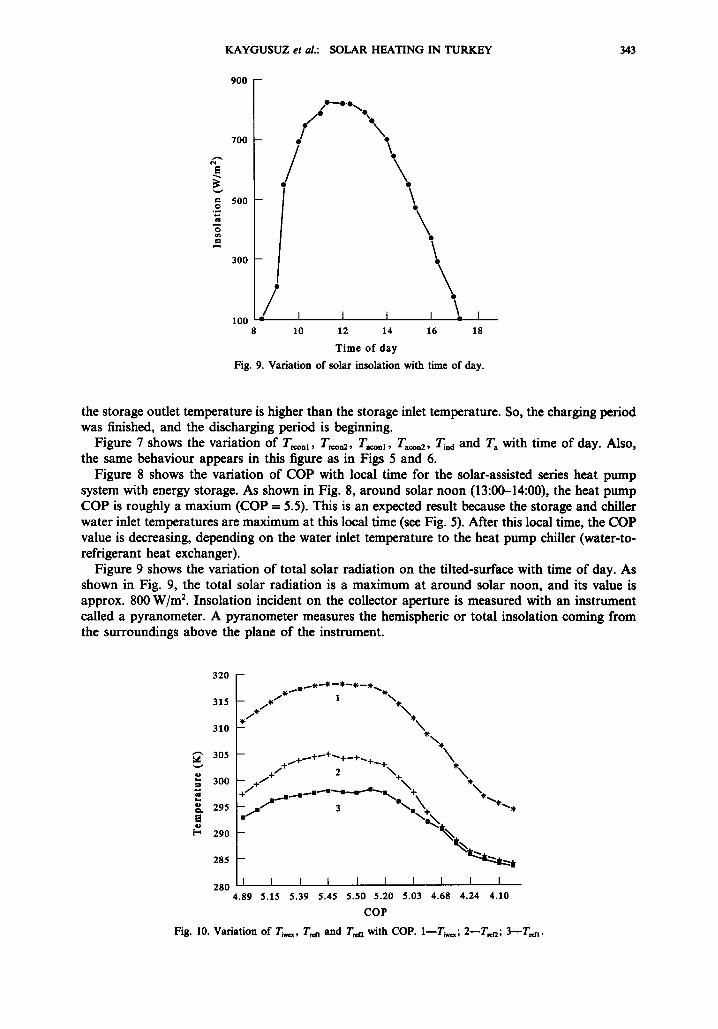
Figure 9 shows the variation of total solar radiation on the tilted-surface with time of day. As shown in Fig. 9, the total solar radiation is a maximum at around solar noon, and its value is approx. 800 W/m 2. Insolation incident on the collector aperture is measured with an instrument called a pyranometer. A pyranometer measures the hemispheric or total insolation coming from the surroundings above the plane of the instrument.
320 --
315 . / . / N . ~
310 -- * \ ~t
~ 305 + +,~+~
o 300 -- 4. / ~'- -*-
-- m / 3 W~m\~ * ~ ' * 295 r ~ X;~
["* 290 -- " ~ , ~
285 " ~ ' ~ , . . ~ t
280 I I I I I I I I I I 4.89 5.15 5.39 5.45 5.50 5.20 5.03 4.68 4.24 4.10
cop Fig. 10. Variation of T-r,~, T ,~ and T ~ with COP. I - -T~,~; 2 - - T ~ ; 3-- -T.~.
344 K A Y G U S U Z et al.: S O L A R H E A T I N G I N T U R K E Y
0 .90 - -
0 ,85 - -
0 .80 --
0 .75 --
• ~ 0 . 7 0 -
r2 o 0 .65 --
0 . 6 0 --
-~ 0 .55- L)
0 . 5 0 -
0 .45 -
0 . 4 0 0 .02
_/+ / + / + j + / - r
+ ~+....+'+"
I - I ~ m l 0.03 0 . 0 4 0 .05
( T f i - T a ) / l
F i g . 11. V a r i a t i o n o f i n s t a n t a n e o u s a n d n e t c o l l e c t o r e f f ic ienc ies a s a f u n c t i o n o f ( T n - - T~)/I .
Figure 10 shows the variation of T~n, T~r2 and T~wex with COP with the solar-assisted series heat pump with energy storage. It is evident that high COP values correspond to the high temperatures of Tr~n, T~f2 and Tiwex. It means that, when the inlet water temperature and refrigerant inlet temperature to the water-sourced evaporator are high, the COP will be high because this is a theoretical rule of the COP definition.
Figure 11 shows the typical flat-plate water cooled solar collector efficiency curves plotted as nc vs (Tr.i- Ta)/Io. There are two efficiencies, one is calculated from equation (4) and the other is calculated from equation (5). As seen from Fig. 11, the slopes of the curves have different signs: one is positive and the other is negative, since the collector water inlet temperature difference has positive and negative values in equations (4) and (5). In equation (4), the collector inlet water temperature difference has a positive value, while in equation (5), it has a negative value. Although the behaviour of the curves are the same, they varied linearly with ( T f , i - - Ta)/lc.
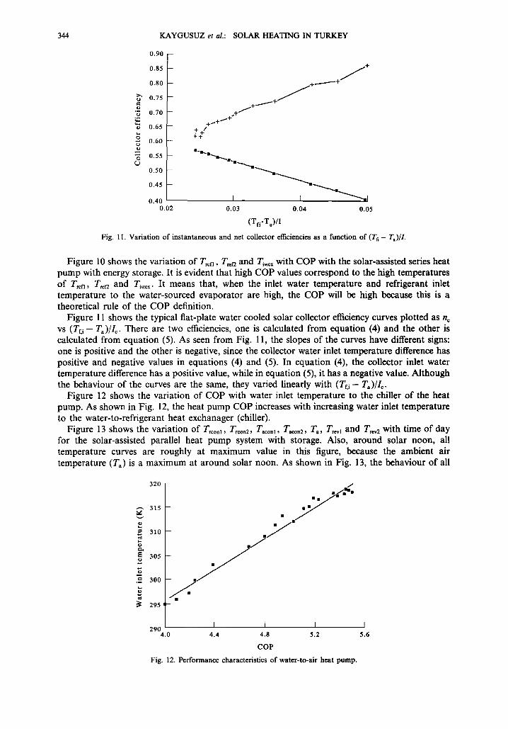
Figure 12 shows the variation of COP with water inlet temperature to the chiller of the heat pump. As shown in Fig. 12, the heat pump COP increases with increasing water inlet temperature to the water-to-refrigerant heat exchanager (chiller).
Figure 13 shows the variation of T, conl, Trio,2, T~co,~, T,~o=2, T~, Tr.~ and T~2 with time of day for the solar-assisted parallel heat pump system with storage. Also, around solar noon, all temperature curves are roughly at maximum value in this figure, because the ambient air temperature (T~) is a maximum at around solar noon. As shown in Fig. 13, the behaviour of all
320
---- 315
310
305
.~ 300
295
. /
. / I I I I
290 4 .0 4 .4 4 .8 5 .2 5 .6
COP
F i g . 12. P e r f o r m a n c e c h a r a c t e r i s t i c s o f w a t e r - t o - a i r h e a t p u m p .
KAYGUSUZ et al.: SOLAR HEATING IN TURKEY 345
Fig.
1
320 ° ° ~ ° ' ° ~ ° ' ° ~ ° ' ° ~ ° ' ° % ' ~ / o / O / O O ~ ' o ~ o ' o ~ o •
2
~, /[_._/ t . ~o ' o~ * ° * " "~e 'D - -e ' *3~ " " ~ " 300
• ~ ~ o / ° . e ~ e - e ' ' " 4 " ' ~ ° - ° ~ o .
8 "~'-o o - -o S - . _ _ 8 - ° ~ o . . " o - - o 280 ~;a,O./.e__ll:e~8:ll~-II:i-- - ..3--o.a~8 •
260 8 t0 12 14 16
Time of day
13. Variation of temperature with time of day for air-sourced heat pump. 1--Trconl; 2--Ta~o~2; 3--T~onl ; 4--T~n2; 5--Ta; 6 - - T ~ ; 7--T~v 2.
the temperature curves is approximately the same as in the other figures that were plotted for the solar-assisted series heat pump system with storage.
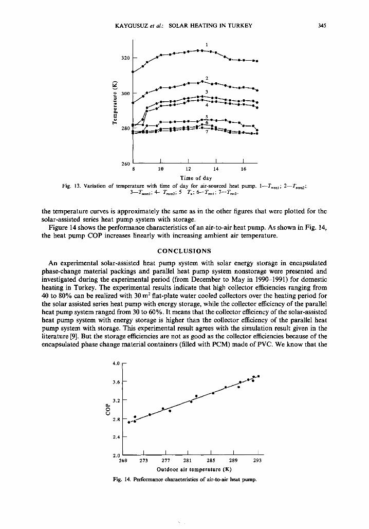
Figure 14 shows the performance characteristics of an air-to-air heat pump. As shown in Fig. 14, the heat pump COP increases linearly with increasing ambient air temperature.
C O N C L U S I O N S
An experimental solar-assisted heat pump system with solar energy storage in encapsulated phase-change material packings and parallel heat pump system nonstorage were presented and investigated during the experimental period (from December to May in 1990-1991) for domestic heating in Turkey. The experimental results indicate that high collector efficiencies ranging from 40 to 80% can be realized with 30 m 2 flat-plate water cooled collectors over the heating period for the solar assisted series heat pump with energy storage, while the collector efficiency of the parallel heat pump system ranged from 30 to 60%. It means that the collector efficiency of the solar-assisted heat pump system with energy storage is higher than the collector efficiency of the parallel heat pump system with storage. This experimental result agrees with the simulation result given in the literature [9]. But the storage efficiencies are not as good as the collector efficiencies because of the encapsulated phase change material containers (filled with PCM) made of PVC. We know that the
4.0 --
3.6
3.2
2.8
2.4 D
2.0 269
- . ~ : / -
I I I I I I 273 277 281 285 289 293
Outdoor air t empera tu re (K)
Fig. 14. Performance characteristics of air-to-air heat pump.

346 KAYGUSUZ et al.: SOLAR HEATING IN TURKEY
thermal conductivity of the PVC is not as good as some metals (for example copper, aluminium, steel, etc.). Therefore, the heat transfer coefficient (or heat transfer rate) from PCM to water (here, water is used as the heat transfer fluid from the container to the water-to-refrigerant or water-to-air heat exchanger in the system) is low. So, the storage efficiency is around 40-60%.
The COP of the solar-assisted series heat pump with energy storage varies from 3.5 to 5.5, depending on the storage temperature. On the other hand, the parallel heat pump COP varies between 2.0 and 3.6, depending on the outdoor air temperature. I f these two COP values are compared, it is seen that the solar-assisted series heat pump COP is higher than the parallel heat pump COP, because the energy storage tank is used as the heat source for the solar-assisted series heat pump system while the outdoor air temperature is used as the heat source for the parallel heat pump system.
I t is evident from the experimental results from this system can technically be used for domestic heating in our regions. But, in order to install this solar-assisted double source heat pump system with energy storage, a detailed economical analysis is needed, because the initial investment costs of this heating system are higher than the conventional heating systems in Turkey. In this study, only a technical analysis was presented. In the future, a detailed economic analysis of this solar-assisted double source heat pump system with energy storage for domestic heating will be presented.
Acknowledgement--Tiffs study was supported by the Karadeniz Technical University Research Fund.
R E F E R E N C E S 1. S. Kakaf, E. Paykof and Y. Yener, Energy Storage Systems, NATO ASI Series, p. 129. Kluwer Academic (1989). 2. J. R. Howe|, R. B. Bannerot and G. V. Vliet, Solar-Thermal Energy System. MfGraw-Hill, New York (1982). 3. J. F. Kreider and F. Kreith, Solar Heating and Cooling. McGraw-Hill, New York (1982). 4. G. A. Lane, Latent Heat Materials, Vol. 1. CRC Press, Boca Raton, Fla (1983), 5. M. Telkes, ASHRAE J. 16, 38 (1974). 6. M. Telkes, Ind. Engng Chem. 44, 1308 (1952). 7. A. Abhat, Sol. Energy 30, 4 (1983). 8. M. Yanabori and T. Masuda, Sol. Energy 36, 169 (1986). 9. T. L. Freeman et al., Sol. Energy 22, 125 (1979).
10. M. Chandrashekar et aL, Sol. Energy 28, 217 (1982). 11. S. K. Chaturvedi and J. Y. Shen, Sol. Energy 33, 155 (1984). 12. B. W. Tleimat and E. D. Howe, Sol. Energy 21, 45 (1978). 13. N. Gfiltekin, T. Ayhan and K. Kaygusuz, Energy Convers. Mgmt 32, 311 (1991). 14. F. C. Parisini, Sol. Energy 41, 193 (1988). 15. A. Brandsetter, Sol. Energy 41, 183 (1988).