sol93025 - urreamedios.urrea.com/catalogo/manuales/sol93025.pdfpara anticiparse a posibles...
TRANSCRIPT

SOL93025
Soldadora de Arco CA/CDAC/DC Arc Welder
MANUAL DE USUARIO Y GARANTÍAUSER’S MANUAL AND WARRANTY
SOL93025 manual.indd 1 12/09/16 3:08 p.m.

E N G L I S H
CONTENT
E S P A Ñ O L
CONTENIDO
Introduction
General safety rules
Work area
Personal safety
Remote operation
Repair
Specific safety rules
Features
Operation instructions
Maintenance & Service
Installation
Technical specifications
Technical data
Transportation & Storage
Troubleshooting
Notes
Warranty policy
Introducción
Normas generales de seguridad
Área de trabajo
Seguridad personal
Operación remota
Reparación
Normas específicas de seguridad
Características
Instrucciones de operación
Mantenimiento y Servicio
Instalación
Especificaciones técnicas
Datos técnicos
Transporte y Almacenamiento
Solucionador de problemas
Notas
Garantía
9
9
9
9
9
10
10
10
11
11
11
12
13
13
14
15
16
3
3
3
3
3
4
4
4
5
5
6
6
7
7
8
15
16
2
IMPORTANTE: Este aparato no se destina para utilizarse por personas (incluyendo niños) cuyas ca-pacidades físicas, sensoriales o mentales sean diferentes o estén reducidas, o carezcan de experiencia o conocimiento, a menos que dichas personas reciban una supervisión o capacitación para el funcio-namiento del aparato por una persona responsable de su seguridad. Los niños deben supervisarse para asegurar que ellos no empleen los aparatos como juguete.
SÍMBOLOS SYMBOLS
PELIGRO, ADVERTENCIA, PRECAUCIÓN: Indica un riesgo personal o la posibilidad de un daño.
DANGER, CAUTION, WARNING: Indicates risk of personal injury and/or the possibility of damage.
SOL93025 manual.indd 2 12/09/16 3:08 p.m.

Esta SOLDADORA DE ARCO DE CA/CD tiene ca-racterísticas que harán su trabajo más rápido y fácil. Seguridad, comodidad y confiabilidad fueron previstos como prioridad para el diseño del mismo, haciendo más fácil su operación.
ADVERTENCIA: Lea atentamente el ma-nual antes de intentar usar este producto. Asegúrese de prestar atención a todas las ad-vertencias y las precauciones de seguridad a lo largo de este manual.
ADVERTENCIA: Lea y entienda todas las instrucciones. El no seguir las instrucciones lis-tadas abajo puede resultar en una descarga eléctrica, fuego y/o lesiones personales serias.
GUARDE ESTAS INSTRUCCIONES PARA FUTURAS REFERENCIAS
• Mantenga su área de trabajo limpia y bien iluminada. Mesas desordenadas y áreas oscuras pueden provocar accidentes. • No use la máquina en atmósferas explosivas, tales como estar en la presencia de líquidos fla-mables, gases o polvo. Los productos eléctricos generan chispas, las cuales pueden provocar incendios. • Mantenga a los observadores, niños y visi-tantes lejos de la máquina mientras la está operando. Las distracciones pueden causarle la pérdida del control. • Se debe tener cuidado de que no caigan ob-jetos extraños sobre la soldadora.• Los niveles de polvo, ácido y suciedad ero-sionable del aire no deben exceder los niveles indicados por las normas vigentes (se excluyen las emisiones resultado del proceso de solda-dura).• Se prohíbe la existencia de materiales explosi-vos o inflamables en el lugar de trabajo.• La soldadora no debe ser expuesta al sol ni a la lluvia. Se debe guardar en lugares de poca humedad, con una temperatura de 10 a 40ºc.• Deberá de colocar la soldadora de tal manera que las rejillas de ventilación no se obstruyan,
deje al menos un espacio de 50 cm para asegu-rar su ventilación.• Asegúrese de que no ingresen elementos me-tálicos extraños al equipo.• Asegúrese de que no haya vibraciones violen-tas en las áreas adyacentes.• Tome medidas para evitar vientos fuertes cuando esté soldando ya que la soldadora con-tiene gas inerte. La velocidad del viento deberá ser menor a 1.0M/s, de lo contrario, se deberá colocar un dispositivo de protección contra el viento.
• Siempre siga las normas de seguridad e hi-giene.• Use artículos de protección para evitar lesio-nes en los ojos o la piel.• Use la máscara de soldar para cubrir su ca-beza mientras trabaja. Mire lo que está sol-dando unicamente a través de los lentes de filtro de la máscara de soldar.• Por ningún motivo toque la salida bipolar de la soldadora (electrodo y pieza de trabajo).
ATENCIÓN: Mientras esté soldando, no to-que el regulador de voltaje.• No deje artículos explosivos ni inflamables en el lugar donde opere.• Los gases y humos producidos por la solda-dura son nocivos para la salud. Asegúrese de trabajar en lugares ventilados o con buena ventilación para que estos humos o emisiones no afecten la respiración.• Recuerde siempre mantener la chispa del arco alejado de las demás personas cuando esté soldando. Esto se debe únicamente a la interferencia de la chispa del arco.• Nunca permita que una persona que no sea el operador desarme o module la soldadora.
Se deben tener en cuenta las siguientes medi-das de precaución dado que la distancia entre el operador y la Soldadora de Arco en lugares apartados puede hacer que el operador no pueda monitorearlo.• Extienda el cable de la soldadora para evitar su sobre calentamiento.
INTRODUCCIÓN
NORMAS GENERALES DE SEGURIDAD
ÁREA DE TRABAJO
OPERACIÓN REMOTA
3
Manual de Usuario
E S P A Ñ O L
SEGURIDAD PERSONAL
SOL93025 manual.indd 3 12/09/16 3:08 p.m.

• Refuerce la protección del cable de la Solda-dora y del cable remoto para evitar que sea aplastado, machucado o dañado de alguna otra manera.• Coloque un cartel en el lugar de instalación que diga “LA SOLDADORA ESTA EN USO, NO TOCAR” para evitar que otra persona se acer-que y toquen.
• La reparación de la Soldadora debe ser lle-vada a cabo solamente por personal calificado. La reparación o el mantenimiento realizado por una persona no calificada puede generar peligro de lesión.• Cuando esté reparando la soldadora use úni-camente partes de reemplazo idénticas. El uso de partes no autorizadas o la falta de segui-miento de las instrucciones de mantenimiento puede ocasionar el riesgo de una descarga eléctrica o lesión.
Cada uno de los puntos que se enumeran a continuación deben de verificarse cuidadosa-mente antes de comenzar a trabajar.• Asegúrese de que el equipo tenga una co-nexión a tierra confiable.• Asegúrese de que no exista ningún corto-circuito en la soldadora y en sus dos salidas de corriente.• Asegúrese de que siempre haya protección aislante en los cables de salida y entrada, ade-más de una conexión confiable.• La soldadora debe de ser revisada por per-sonal calificado después de un periodo de seis meses de trabajo, por lo que debe de tomar en cuenta lo siguiente:- Mantenga una rutina de limpieza, remueva el polvo excesivo y verifique que no haya partes sueltas.- Cambie el control del cable de la soldadora para anticiparse a posibles deterioros.• Reemplace el cable de alimentación de la sol-dadora tan pronto como se descubra que está roto o dañado.• Asegúrese de que haya suficiente suministro de energía para que la soldadora trabaje co-rrectamente.
NOTA: Para acceder a cualquier fuente de energía es necesario utilizar el equipo de pro-tección necesario. ATENCIÓN: Antes de abrir su soldadora des-conecte de la fuente de energía eléctrica. ATENCIÓN: No dude en contactar nuestro centro de servicio autorizado para asistencia técnica cuando se encuentre con problemas de operación o que considere dificil de reparar.
Esta soldadora debe ser operada por una sola persona. Las partes principales de esta má-quina son el transformador y el núcleo móvil. Se caracteriza por un suave y estable arco con un minimo de salpicadura. La soldadora puede trabajar con electrodos ácidos, alcalinos y elec-tródos celulósicos. Se obtiene excelentes resultados al soldar en acero suave, acero de medio carbono, aleacio-nes de acero suave, acero inoxidable y otros metales no ferrosos tales como aleación niquel y aleación de cobre. La soldadora puede ser utilizada en la construcción naval, calderas, re-cipientes a presión, en la construcción, plantas eléctricas, minería, etc.
ESTRUCTURA DE LA SOLDADORA La soldadora tiene una estructura simple, para facilitar su transporte; cuenta con empuñadura y ruedas.El núcleo móvil de la soldadora y sus cuatro co-nexiones se encuentran en la parte frontal de la maquina. Según las necesidades, esta soldadora puede ser utilizados tanto en la soldadura de arco de corriente alterna (CA) y corriente directa (CD). Constituida por dos partes principales esta má-quina de soldar cuenta con un embobinado primario y embobinado secundario, con un nú-cleo de hierro. El interruptor, la luz que indica el encendido y la manivela de ajuste de corriente de salida se encuentra en el panel frontal. El ventilador de enfriamiento, caja de entrada de alimentación de conexión y tornillo de la tierra se encuen-tran en la parte posterior de la máquina.
REPARACIÓN
NORMAS ESPECÍFICAS DE SEGURIDAD
4
CARACTERÍSTICAS
SOL93025 manual.indd 4 12/09/16 3:08 p.m.

1. VENTANA DE INDICACIÓN DE CORRIENTE.2. GANCHOS PARA TRANSPORTE.3. LUZ INDICADORA DE ENCENDIDO.4. INTERRUPTOR DE ENCENDIDO/APAGADO.5. MANIVELA.6. SALIDA DE CORRIENTE DIRECTA (CD).7. SALIDA DE CORRIENTE ALTERNA (AC).
ATENCIÓN: Operar la soldadora en forma apropiada asegura el funcionamiento satisfac-torio y prolonga la vida útil del equipo de sol-dar. Al utilizar la soldadora, asegúrese de que haya una buena conexión de entrada, salida y a tierra antes de conectarla a la electricidad.
PARA SOLDARConecte el cable de alimentación y los cables de salida de la soldadura (porta electrodo y pieza de trabajo) tal como lo indica el Manual del Usuario. Por último, accione el interruptor y el ventilador comenzará a funcionar. ATENCIÓN: Cuando haya distancia entre la soldadora y la pieza de trabajo, el cable de sol-dar debe ser mayor para evitar que la caída de tensión sea mayor a 4 V.
AJUSTE DE LA CORRIENTE DE LA SOLDADORAGire la manivela para mover el indicador de corriente al valor que se requiera. Después del ajuste, realice pruebas para asegurarse de que la corriente sea la correcta. Si es necesario vuelva a girar el volante para ajustar la corriente. A continuación, inicie a soldar.
NOTA: Los electrodos se queman a altas tempe-raturas. Al reemplazarlos, use guantes. El resto de electrodo reemplazado se debe colocar en un contenedor metálico. No use el portaelec-trodo para quitar la escoria del electrodo.
REMOCIÓN DE RESIDUOSUna vez que terminó de soldar, utilice un mar-tillo especial (martillo de herrero) para des-prender los restos de soldadura de la superficie de la barra de soldar.NOTA: Quite los restos de soldadura una vez que éstos se enfriaron y endurecieron.Para evitar lastimar a otras personas con los restos de soldadura, nunca oriente el martillo hacia personas que se encuentren cerca.
ATENCIÓN: El voltaje de soldadura es siem-pre alto, por lo tanto, sea muy cauteloso antes de reparar el equipo para evitar shocks acci-dentales.
• La máquina de soldar es una soldadora ro-busta. Su uso y mantenimiento apropiados pueden prolongar su vida útil. La reparación de la soldadora debe estar a cargo de personal calificado. Recomendamos a nuestros clientes ponerse en contacto con nuestra empresa o con nuestros distribuido-res o agentes para solicitar servicio técnico, reparación o accesorios; cada vez que tengan dificultades para solucionar algún problema técnico.• Si la soldadora ha sido recién instalada o haya estado en desuso durante algún tiempo, se deberán inspeccionar las resistencias aislantes entre cada bobinado y entre el bobinado y la caja, en forma exacta, no debiendo ser inferior a 2.5 MΩ.• Mantenga la soldadora alejada de la lluvia, la nieve y de largas exposiciones al sol, si se usara al aire libre.• Si no se usa el Equipo de Soldar por un largo tiempo o en forma temporaria, se debe mante-ner seco y en un lugar con buena ventilación, que lo mantenga aislado de la humedad, polvo o gases tóxicos. Los rangos de temperatura to-lerables son -25 a +55°C, y la humedad relativa no puede ser mayor al 90%.
5
Manual de Usuario
E S P A Ñ O L
INSTRUCCIONES DE OPERACIÓN
2
3
6
5
7
4
1
MANTENIMIENTO Y SERVICIO
SOL93025 manual.indd 5 12/09/16 3:08 p.m.

• Periódicamente controle los cables de en-trada y salida del equipo para asegurarse de que estén firmes y bien conectados. Se deben realizar controles mensuales cuando se utilice regularmente. • Periódicamente se deberá limpiar el equipo y hacer el mantenimiento técnico respectivo. Controle los sujetadores de la máquina, hierro móvil (magnetismo), los tornillos reguladores de corriente, etc. para asegurarse que no exis-tan problemas de conexión.• Desconecte de la fuente de poder cada vez que realice algún trabajo de control. Solo per-sonal calificado puede abrir la soldadora.
El grado de protección de la caja de la solda-dora es IP21S. Nunca ponga los dedos dentro del equipo; así como tampoco introduzca ele-mentos metálicos. No utilice la soldadora con fuerza desmedida.
CONEXIÓN ENTRE LA SOLDADORA Y LA PUESTA A TIERRA ATENCIÓN: La soldadora debe estar bien co-nectado a tierra antes de comenzar a operar y no se deberá desconectar hasta que se haya terminado el trabajo de soldadura. De lo con-trario, podría ocasionar lesiones serias y/o pro-ducir una descarga eléctrica. Es obligatorio tener una conexión paralela cuando el equipo de soldar utiliza la misma puesta a tierra que otras máquinas. Nunca se debe utilizar una co-nexión en serie. El cable que conduce a tierra no puede tener dimensiones de sección meno-res a la del cable de entrada de energía.
CONEXIÓN ENTRE EL SOLDADORA Y LA FUENTE DE ALIMENTACIÓNCuando la soldadora está conectada a tierra (aterrizado), siempre asegúrese de que el vol-taje sea el indicado al de la tensión de la placa de la soldadora.
Los tornillos de conexión debe estar bien apre-tados. Para obtener más información consulte la Conexión de entrada de Dibujo (fig.1).1. Entrada de energía. Caja de conección.2. Usando un perno para el cable de tierra.
6
ATENCIÓN: El área de sección transversal mí-nima del cable de alimentación debe ser con-forme a los establecido en la siguiente tabla:
INTERRUPTOR ≥160 A CAPACIDAD DE FUSIBLE 120 A SECCIÓN TRANSVERSAL ≥16 mm²
AVISO: La corriente de disparo del fusible es de dos veces su corriente nominal de trabajo.
CONEXIÓN DE SALIDA
SOLDADORA POR ARCO CD Conecte los cables de salida de acuerdo con el dibujo anterior y atornillar. AVISO: Si los conectores no se han ajustado bien, la junta de conexión interior y el cable de soldadura se puede quemar.
SOLDADORA POR ARCO CA Conecte los cables de salida de acuerdo con el dibujo anterior y atornillar. AVISO: Si los conectores no se han ajustado bien, la junta de conexión interior y el cable de soldadura se puede quemar.
LUGAR DONDE SE TRABAJARÁ CON LA SOL-DADORARango de Temperatura: Mientras se está sol-dando: -10 a 40°C.
INSTALACIÓN
2
1
Conector a la pieza de trabajo (CD)
Conector al porta electrodo (CD)
Conector a la pieza de trabajo (CA)
Conector al porta electrodo (CA)
ESPECIFICACIONES TÉCNICAS
SOL93025 manual.indd 6 12/09/16 3:08 p.m.
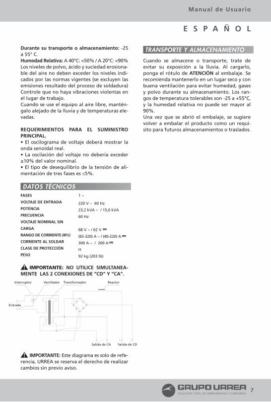
Durante su transporte o almacenamiento: -25 a 55° C.Humedad Relativa: A 40°C: <50% / A 20°C: <90%Los niveles de polvo, ácido y suciedad erosiona-ble del aire no deben exceder los niveles indi-cados por las normas vigentes (se excluyen las emisiones resultado del proceso de soldadura) Controle que no haya vibraciones violentas en el lugar de trabajo.Cuando se use el equipo al aire libre, mantén-galo alejado de la lluvia y de temperaturas ele-vadas.
REQUERIMIENTOS PARA EL SUMINISTRO PRINCIPAL.• El oscilograma de voltaje deberá mostrar la onda senoidal real. • La oscilación del voltaje no debería exceder ±10% del valor nominal.• El tipo de desequilibrio de la tensión de ali-mentación de tres fases es ≤5%.
IMPORTANTE: NO UTILICE SIMULTANEA-MENTE LAS 2 CONEXIONES DE “CD” Y “CA”.
IMPORTANTE: Este diagrama es solo de refe-rencia, URREA se reserva el derecho de realizar cambios sin previo aviso.
Cuando se almacene o transporte, trate de evitar su exposición a la lluvia. Al cargarlo, ponga el rótulo de ATENCIÓN al embalaje. Se recomienda mantenerlo en un lugar seco y con buena ventilación para evitar humedad, gases y polvo durante su almacenamiento. Los ran-gos de temperatura tolerables son -25 a +55°C, y la humedad relativa no puede ser mayor al 90%.Una vez que se abrió el embalaje, se sugiere volver a embalar el producto como un requi-sito para futuros almacenamientos o traslados.
7
Manual de Usuario
E S P A Ñ O L
DATOS TÉCNICOS
TRANSPORTE Y ALMACENAMIENTO
FASES
VOLTAJE DE ENTRADA
POTENCIA
FRECUENCIA
VOLTAJE NOMINAL SIN
CARGA
RANGO DE CORRIENTE (40%)
CORRIENTE AL SOLDAR
CLASE DE PROTECCIÓN
PESO
1 ~
220 V ~ 60 Hz
23,2 kVA ~ / 15,6 kVA
60 Hz
68 V ~ / 62 V
(65-320) A ~ / (40-220) A
300 A ~ / 200 A
H
92 kg (203 lb)
…–
…–…–
Interruptor
Entrada
Ventilador Transformador
Salida de CA Salida de CD
Reactor
SOL93025 manual.indd 7 12/09/16 3:08 p.m.

8
PROBLEMAS1
2
3
4
5
6
7
8
Electrificación de la caja.
Mucho ruido cuando está conectado.Se fundió el fusible.
Corriente de salida muy escasa; falta de golpeteo o inestabilidad del arco.
El bobinado se calienta, he-cha humo y el fusible está quemado.
No hay golpeteo o hay di-ficultades en la ignición del arco una vez que se encen-dió el equipo.
El ventilador de enfriado no está funcionando correcta-mente.
Mucho ruido al soldar.
Otros
1. El bobinado principal entra a la caja.2. El bobinado secundario entra a la caja.3. Los bobinados primario y secun-dario se encuentran con el núcleo de hierro.4. El cable de entrada toca la caja.
1.Corto circuito en la bobina pri-maria y secundaria;2. Se tocan los adaptadores de cables.3. Fusible demasiado chico.
1. Voltaje de entrada demasiado bajo y el voltaje fluctúa.2. El cable de soldadura es muy Delgado y largo; la conexión entre el cable de tierra y la pieza de tra-bajo no está bien aseguradas.3. La conexión entre el cable de soldadura y la terminación de sali-da del transformador no está bien asegurada.4. Tornillo y tuerca de regulación desgastados.5. No funciona el Interruptor de cambios.
1. Sobrecarga.2. Corto circuito parcial en los bobinados primario y secundario.3. Está roto el ventilador de en-friado.
1. No hay voltaje de entrada desde la fuente de energía.2. El interruptor está en la posi-ción de apagado.3. La dimensión de sección del cable de entrada es demasiado corta o el cable de soldadura es demasiado largo.4. Corto circuito parcial en el bobinado.
1. El capacitor de inicio está desha-bilitada o rota.2. Se quemó el núcleo en el motor del ventilador.3. Falla de contacto o desco-nexión.
1. Separación irregular entre el núcleo de hierro móvil y el está-tico.2. El núcleo de hierro se mueve bruscamente, afloja el tornillo de sujeción y se rompe el obturador.
1. Para 1.2.3, desconecte la fuente de energía. Use la resistencia del multímetro para medir. Mientras una varilla toca la caja o el núcleo de hierro, la otra mide el bobinado primario y secundario; si la segunda se mueve está indicando una fuga de electricidad. No toque la caja y aísle entre el bobinado y el núcleo de hierro con los mismos materiales de aislación.2. Libere el cable o el cable de soldar de cualquier posición donde se toquen.
1. Encuentre dónde está el corto circuito. Repare.
2. Separe los cables.3. Reemplace el fusible.
1. Ajuste la corriente de entrada hasta el valor nominal o aumenteLa capacitancia de suministro.2. Aumente la dimensión de sección del cable de soldadura para asegurar una buena conexión entre el cable a tierra y la pieza de trabajo.
3. Asegure una buena conexión entre el cable de soldadura y la terminación de salida del transformador.
4. Reemplace las partes gastadas.
5. Reemplace el Interruptor de cambios.
1. Interrumpa la operación. Reinicie las tareas en conformidad con los requerimientos de ciclos de trabajo una vez que los bobinados se hayan enfriado. 2. Repare el corto circuito o reemplace el bobinado.3. Repare o reemplace el ventilador de enfriado.
1. Controle el interruptor, el fusible y el cable de entrada para asegurarse que estén funcionando normalmente. 2. Coloque el interruptor en posición de encendido.
3. Use un cable más grande o un cable de soldadura.
4. Repare la zona en corto circuito en el bobinado.
1. Reemplace el capacitor.
2. Reemplace el bobinado o el motor.
3. Controle el cable para solucionar la falla.
1. Reajuste la separación entre el núcleo de hierro móvil y el es-tático.
2. Ajuste el obturador, afirme el tornillo, reemplace las partes ro-tas y re-ensamble el núcleo de hierro conforme al tipo original.
Por favor, contacte al fabricante/ proveedor.
ANÁLISIS SOLUCIONES
SOLUCIONADOR DE PROBLEMAS
SOL93025 manual.indd 8 12/09/16 3:08 p.m.
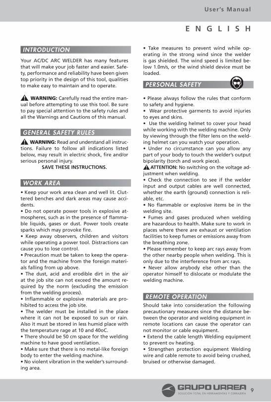
Your AC/DC ARC WELDER has many features that will make your job faster and easier. Safe-ty, performance and reliability have been given top priority in the design of this tool, qualities to make easy to maintain and to operate.
WARNING: Carefully read the entire man-ual before attempting to use this tool. Be sure to pay special attention to the safety rules and all the Warnings and Cautions of this manual.
WARNING: Read and understand all instruc-tions. Failure to follow all indications listed below, may result in electric shock, fire and/or serious personal injury.
SAVE THESE INSTRUCTIONS.
• Keep your work area clean and well lit. Clut-tered benches and dark areas may cause acci-dents.• Do not operate power tools in explosive at-mospheres, such as in the presence of flamma-ble liquids, gases or dust. Power tools create sparks which may provoke fire.• Keep away observers, children and visitors while operating a power tool. Distractions can cause you to lose control.• Precaution must be taken to keep the opera-tor and the machine from the foreign materi-als falling from up above.• The dust, acid and erodible dirt in the air at the job site can not exceed the amount re-quired by the norm (excluding the emission from the welding process).• Inflammable or explosive materials are pro-hibited to access the job site.• The welder must be installed in the place where it can not be exposed to sun or rain. Also it must be stored in less humid place with the temperature rage at 10 and 40oC.• There should be 50 cm space for the welding machine to have good ventilation.• Make sure that there is no metal-like foreign body to enter the welding machine.• No violent vibration in the welder’s surround-ing area.
• Take measures to prevent wind while op-erating in the strong wind since the welder is gas shielded. The wind speed is limited be-low 1.0m/s, or the wind shield device must be loaded.
• Please always follow the rules that conform to safety and hygiene.• Wear protective garments to avoid injuries to eyes and skins.• Use the welding helmet to cover your head while working with the welding machine. Only by viewing through the filter lens on the weld-ing helmet can you watch your operation.• Under no circumstance can you allow any part of your body to touch the welder’s output bipolarity (torch and work piece). ATTENTION: No switching on the voltage ad-justment when welding.• Check the connection to see if the welder input and output cables are well connected, whether the earth (ground) connection is reli-able, etc.• No flammable or explosive items be in the welding site.• Fumes and gases produced when welding are hazardous to health. Make sure to work in places where there are exhaust or ventilation facilities to keep fumes or emissions away from the breathing zone.• Please remember to keep arc rays away from the other nearby people when welding. This is only due to the interference from arc rays.• Never allow anybody else other than the operator himself to dislocate or modulate the welding machine.
Should take into consideration the following precautionary measures since the distance be-tween the operator and welding equipment in remote locations can cause the operator can not monitor or cable equipment.• Extend the cable length Welding equipment to prevent ov heating.• Strengthen protection equipment Welding wire and cable remote to avoid being crushed, bruised or otherwise damaged.
INTRODUCTION
GENERAL SAFETY RULES
WORK AREA
REMOTE OPERATION
PERSONAL SAFETY
9
User’s Manual
E N G L I S H
SOL93025 manual.indd 9 12/09/16 3:08 p.m.

• Post a sign at the installation site to say “WELDING EQUIPMENT IN USE, DO NOT TOUCH” to prevent other people to come and be touched.
• Repair of Arc Welding should be carried out only by qualified personnel. The repair or maintenance performed by a qualified person-ano can create risk of injury.• When repairing the machine using only gen-uine replacement parts. Follow the instructions in the maintenance section of this manual. The use of unauthorized parts or failure to follow maintenance instructions may create a risk of electric shock or injury.
Each item listed below must be carefully chec-ked before operation:• Make sure that the welding machine has re-liable earth connection.• Make sure that there is always sound output and input wire connection without any short circuit of the output side.• Make sure there is always sound Insulative protection of the input and output wire and reliable connection.Regular check needs to be conducted by the qualified personnel after the welder has been installed over a period of not later than six months, which involves as follows:• Routine cleaning needs to be done to make sure that there is no abnormal loose parts hap-pening in the welding machine while regular dust cleaning is necessary.• Check the welding cable to see if it can conti-nue to be used before it is worn out.• Replace the welder’s input cable as soon as it is found to be broken or damaged.• Make sure whether there is enough power supply to make the welding machine work pro-perly and the input power must load the safety protection device. WARNING: Cut off the power supply before opening the case to check. IMPORTANT: Please do not hesitate to con-tact the manufacturer or the agent for tech-nical assistance whenever you come across the
problems you can not work out or you may deem difficult to fix.
Arc Welder is an arc welding power source manually operated by a single person. The main parts of this machine are transformer, rectifier and reactor. It is current stepless ad-justment welding machine. It is characterized by soft and stable arc, little spatter and good welding performance. This machine can work with acid electrode, alkaline electrode and cel-lulosic electrode. It can get satisfied effect to welding mild steel, medium carbon steel, mild alloy steel, stainless steel and some nonferrous metals such as nickelic alloy and copper alloy. It can be used in ship building, boiler, pressure container, construction, electric power, mining machinery industries.
WELDER’S STRUCTUREArc Welding Machines adopts the movable box like structures.With a handle, wheels and hoisting ring at the top of the case and four wheels at the bottom, it is very convenient to carry and transport. There are switch, power indicating light, cur-rent adjusting hand wheel, output socket on the front panel (AC/DC), and cooling fan, pow-er input connection box and earth bolt on the back of machine.
KNOW YOUR TOOL
FEATURES
REPAIR
SPECIFIC SAFETY RULES
10
2
3
6
5
7
4
1
SOL93025 manual.indd 10 12/09/16 3:08 p.m.

1. CURRENT INDICATING WINDOW.2. HOOK.3. POWER INDICATOR.4. ON/OFF SWITCH.5. HANDWHEEL.6. DC OUTPUT.7. AC OUTPUT.
WARNING: To properly operate the welder can assure the welder to work satisfactorily and can prolong welder’s operating life. When using the welder, please make sure there is a good connection of input, output and earth (ground) before connecting the power source.
WELDINGConnect the power supply cord and welding output cable according to the operator’s ma-nual and then connect the power supply, finally turn on the switch, and the fan starts working. WARNING: When there is some distance between the welder and the work piece, the sectional dimension of the welding cable must be made bigger just to keep the welder output potential drop out not more than 4V.
WELDING CURRENT PRESETTINGTurn the hand wheel to move current indica-tor to value needed. After presetting, do the testing to make sure the preset current is co-rrect. Turn the hand wheel to adjust current, if fine adjustment is needed. Then start welding. NOTE: Electrode burns at high temperature. Please do not use hand to replace it. The repla-ced electrode end should be placed in a metal container. Do not use the electrode holder to clamp the electrode coating.
SLAG REMOVALWhen the welding job is finished, please use the special slag hammer to knock off the slag on the surface of welding rail.NOTE: Only until the slag cools off and beco-mes hardened can the removal work starts. To avoid the slag injuring people, never point at the nearby people when you remove slag.
WARNING: The welder voltage is always hig-her, so the safety precaution should be taken before repair to avoid accidental shock.Switch off the power source each time when conduc-ting the examination job. The untrained peo-ple are not allowed to open the case.
• Arc welders are a kind of portable and mo-veable arc welding machine. Right performan-ce and maintenance may prolong its operating life. Only the qualified personnel are allowed to be in charge of repairing. It is strongly re-commended customers contact with our com-pany or agent for technical, repairing, acces-sories supply and service when they feel unable to work out the technical hitch or problems.•Before conducting the repair work, the power should be cut off first.• The newly installed welder or which haven’t been in use for some time needs to be surve-yed the insulation resistances between each winding and every winding to case with milli-meter, which can not be less than 2.5 MΩ.• Keep from the rain, snow and long term exposing to sunlight when welder is used outdoor.• If the welder is not in use either for a long time or temporarily, it should be kept dry and have good ventilation to free it from moisture, erosible or toxic gas. The tolerable temperatu-re ranges from -25 to +55°C, and the relative humidity can not be more than 90%.• Regularly check the input & output cables of welder to guarantee them right and firmly con-nected and avoid them being exposed. Check should be taken once every month when fixed using and every check taken when removing.• Dust removal is needed every year. Check the machine’s fasteners, moving-iron, current re-gulation screws, etc to make sure there are no loose connection problems.
Arc welder’s case protection grade is IP 21S. It is forbidden to put in a finger or insert a round bar less than 12 mm (metal bar in particular) into the welder. No heavy force can be emplo-yed on the welder.
11
User’s Manual
E N G L I S H
MAINTENANCE & SERVICE
OPERATION INSTRUCTIONS
INSTALLATION
SOL93025 manual.indd 11 12/09/16 3:08 p.m.

GROUNDING WARNING: The welding machine should be well connected with earth before operation and no disconnection work is allowable befo-re the welding job is finished. Or it may cause an electric shock and harmful injuries. Parallel connection is a must when the welding machi-ne is using the same earth equipment together with the other machines. Never can the con-nection in series be used here. The sectional di-mension of the earth conducting wire cannot be less than that of power cord.
CONNECTION BETWEEN WELDER AND POWER SOURCEWhen the welder is connected with the earth (ground), please always make sure that the voltage must be in conformity with the volt-age given on the welder’ s indication plate and it must be joined with the fastener. The con-nection screws must be tightened and well se-cured. The input wire must be fastened on the conductor clamp attached to the welder. For details please see the next illustration:1. Power input. Conection Box.2. Using bolt on the earth wire.
ATTENTION: The minimum copper’s sectional area of the power cord must be in line with the requirement prescribed in next table:
AIR SWITCH ≥160 A FUSE (RATED CURRENT) 120 A POWER WIRE ≥16 mm²
NOTICE: The melting current of the fuse is two times of its rated working current.
OUTPUT CONNECTIONDC ARC WELDINGConnect the output cables according to the above sketch and screw down. The work clamp is connected to the work piece. The electrode holder of the welding cable is for welding after installing the electrode.
12
TECHNICAL SPECIFICATIONS
NOTICE: If the connectors haven’t been tweaked tightly, the inner connection board and the welding cable will be burn out.
AC ARC WELDINGConnect the output cables according to the above sketch and screw down. The work clamp is connected to the work piece. And the elec-trode holder of the welding cable is for weld-ing after installing the electrode. NOTICE: If the connectors haven’t been tweaked tightly, the inner connection board and the welding cable will be burn out.
Environment to which the product is subjectThe surrounding temperature range: When welding: -10 to +40°C. During transport or in storage: -25 to +55° CRelative humidity: when at 40°C: <50%. / when at 20°C: <90%.The dust, acid and erodible materials in the air can not exceed the amount required by the norm (apart from the emissions from the welder). No violent vibration at the job site.Keep from raining and high temperature when it is used outdoor.
REQUIREMENT FOR MAIN SUPPLY• The voltage oscillogram should display actual sine wave.• The oscillation of the supplied voltage should not exceed ±10% of the rated value.• The unbalanced rate of voltage of three phases power supply shall be ≤5%.
2
1
Connector for workpiece (DC)
Connector for elec-trode holder (DC)
Connector for workpiece (AC)
Conector for elec-trode holder (AC)
SOL93025 manual.indd 12 12/09/16 3:08 p.m.
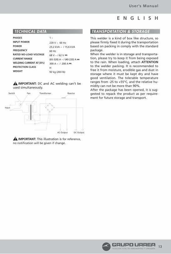
IMPORTANT: DC and AC welding can’t be used simultaneously.
IMPORTANT: This illustration is for reference, no notification will be given if change.
This welder is a kind of box like structure, so please firmly fixed it during the transportation based on packing in comply with the standard package.When the welder is in storage and transporta-tion, please try to keep it from being exposed to the rain. When loading, attach ATTENTION to the welder packing. It is recommended to free it from moisture, erodible gas and dust in storage where it must be kept dry and have good ventilation. The tolerable temperature ranges from -25 to +55°C, and the relative hu-midity can not be more than 90%.After the package has been opened, it is sug-gested to repack the product as per require-ment for future storage and transport.
13
User’s Manual
E N G L I S H
TECHNICAL DATA
Switch
Input
Fan Transformer
AC Output DC Output
Reactor
TRANSPORTATION & STORAGEPHASES
INPUT POWER
POWER
FREQUENCY
RATED NO-LOAD VOLTAGE
CURRENT RANGE
WELDING CURRENT AT (35%)
PROTECTION CLASS
WEIGHT
1 ~
220 V ~ 60 Hz
23,2 kVA ~ / 15,6 kVA
60 Hz
68 V ~ / 62 V
(65-320) A ~ / (40-220) A
300 A ~ / 200 A
H
92 kg (203 lb)
…–
…–…–
SOL93025 manual.indd 13 12/09/16 3:08 p.m.

14
TROUBLESHOOTING
BREAKDOWN
1
2
3
4
5
6
7
8
Case electrification.
Big noise when it’s switched on; power source fuse mel-ted away.
Too small amount of output current; No striking or the arc becomes unsteady.
The winding getting hot, smoking and the fuse mel-ted away.
No striking or difficult to ig-nite arc after the welder is switched on.
Cooling fan not working properly.
Big noise when welding.
Others
1. Primary winding run into case.2. Secondary winding run into case.3. Primary and secondary winding meet the iron core.4. Input wire happens to touch the case.
1. Short-circuit in the primary and the secondary spool.2. The wire adaptor meet each other.3. Fuse too small.
1. Input voltage too low and the voltage undelates.2. Welding cable too thin and too long; The connection between the earth wire and the work piece not well secured, with the result of too much of resistence.3. The connection between the welding cable and the transfor-mer output and not well secured, with the result of too much of resistance.4. Regulation screw and nut worn out.
1. Overload running.2. Partial short-circuit on the pri-mary and secondary winding.3. Cooling fan broken.
1. No input voltage from the power source.2. Switch is in off position.3. Input wire sectional dimension is too small or welding cable too long.4. Partial winding short circuit.
1. Starting capacitance disable or broken.2. Coil in fan’s motor burned out.3. Contact failure or disconnec-tion.
1. Uneven gap between the mo-ving iron core and the static iron core.
1. Regarding 1.2.3, disconnect the power source. Use the multimeter’s low resistance to measure. When one stick touches the case or the iron core while another one measures the primary and secondary winding, that indicates an electric leakage if the second swings. Keep the case free from being touched, and have insulation treatment between the winding and the iron core with the same insulation materials.2. Rid the wire or the welding cable of any position which is being touched .
1. Find out the short circuit on the winding get it repaired.
2. Keep the wires apart.
3. Replace the fuse.
1. Adjust the input current up to the rated value, or increase the main supply capacitance.2. Enlarge the welding cable’s sectional dimension to secure a sound connection between the earth wire and the work piece.
3. Secure a sound connection between the welding cable and the transformer output end.
4. Replace the worn-out parts.
1. Stop operation. Resume operation in conformity with the duty cycle requirement after the winding has cooled off. 2. Repair the short-circuit part or replace the winding.3. Repair or replace cooling fan.
1. Check input power switch, fuse, input wire to enable them to work normally. 2. Turn on the switch to make the welder’s switch in on position.3. Use a bigger wire or a welding cable.
4. Repair the short circuit area on winding.
1. Replace the capacitor.
2. Replace winding or motor.3. Check the wire to work out the failure.
1. Readjust the gap between the moving iron core and the static iron core.
Please contact with our company.
ANALYSIS SOLUTIONS
SOL93025 manual.indd 14 12/09/16 3:08 p.m.

NOTES / NOTAS
15
User’s Manual / Manual de Usuario
SOL93025 manual.indd 15 12/09/16 3:08 p.m.

16
Urrea Herramientas Profesionales S. A. de C. V. Warranties this product for a period of 1 year in its parts, components and manual labour against any manufacture defect from the purchasing date.
Purchase date: ____/____/____Product:____________________Brand:______________________Model:______________________
______________________________Distributor Seal and Signature
Sold and Imported by:Urrea Herramientas Profesionales S.A. de C.V. km 11,5 Carretera A El Castillo, El Salto, Jalisco, México. C. P. 45680, Tel. (33) 3208 7900, RFC UHP900402Q29
Terms:In order to make warranty effective you must pre-sent the product along with the warranty properly fillled and signed to an authorized distributor or service center.
Urrea Herramientas Profesionales S. A. de C. V. will cover the transportation cost related to the warranty.*
This warranty is not applicable in the following cases:· When the product has not been used according to normal conditions or natural wear of its parts. · When the product has not been used according with this user’s manual instructions. · When the product has been fixed or modified by unauthorized or unqualified person.
Urrea Herramientas Profesionales S. A. de C. V. garantiza este producto por el termino de 1 año en sus piezas, componentes y mano de obra contra cualquier defecto de fabricación a partir de la fecha de entrega.
Fecha de venta: ____/____/____Producto: ___________________Marca: ______________________Modelo: ____________________
______________________________Sello y firma de distribuidor
Comercializado e Importado por:Urrea Herramientas Profesionales S.A. de C.V. km 11,5 Carretera A El Castillo, El Salto, Jalisco, México. C. P. 45680, Tel. (33) 3208 7900, RFC UHP900402Q29
Condiciones:Para hacer efectiva la garantía deberá presentar el producto junto con la poliza de garantia debida-mente firmada y sellada por el establecimiento donde la adquirio, en cualquiera de los centros de servicio autorizados. Los gastos de transportación que se deriven del cumplimiento de la garantía seran cubiertos* por:Urrea Herramientas Profesionales S. A. de C. V.
Esta garantía no será valida en los siguientes casos: Cuando el producto haya sido utilizado en con-diciones distintas a las normales o al desgaste natural de sus partes. Cuando el producto no haya sido operado de acu-erdo al instructivo de uso que lo acompaña. Cuando el producto haya sido alterado o reparado por personas no autorizadas.
E S P A Ñ O L
POLIZA DE GARANTÍA
E N G L I S H
WARRANT POLICY
SOL93025 manual.indd 16 12/09/16 3:08 p.m.